centralized ac system
DESCRIPTION
TRANSCRIPT
CENTRALIZED AIR
CONDITIONING SYSTEMS
AISWARYA AMALU ARJUN FEBIN SAMEER SANOOB VISHNU VIJAY
GROUP 4

CONTENTS
Centralized AC
systems
AHU
Fan coil
details
Comparison with
non-centraliz
ed systems
Central air conditioning systems serve multiple spaces from one base location. These typically use chilled water as a cooling medium and use extensive ductwork for air distribution
Continuing Education and Development, Inc. 9 Greyridge Farm Court Stony Point, NY 10980
CENTRALISED AIR CONDITIONING
WORKING OF A CENTRALISED AC SYSTEM
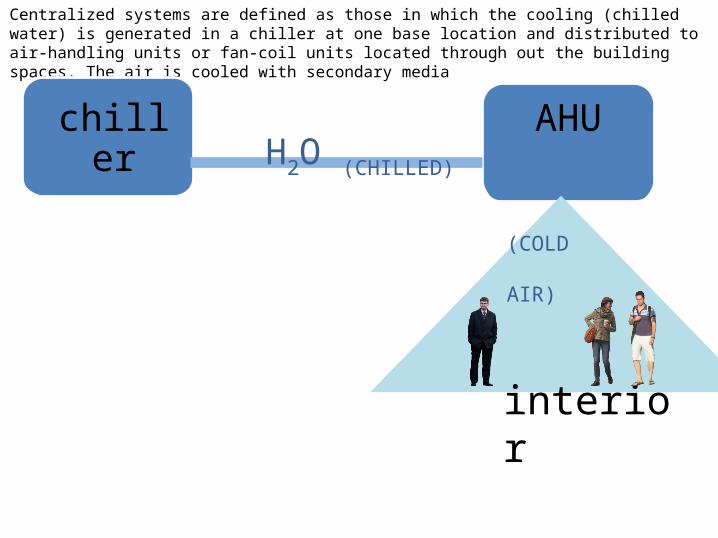
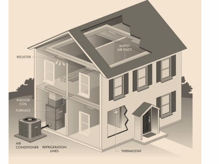
Centralized systems are defined as those in which the cooling (chilled water) is generated in a chiller at one base location and distributed to air-handling units or fan-coil units located through out the building spaces. The air is cooled with secondary media
chiller AHU
interior
H2O (CHILLED)
(COLD AIR)
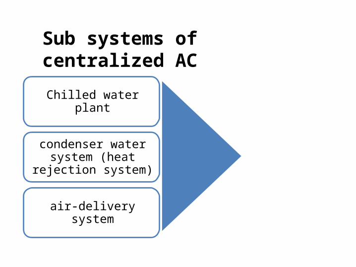
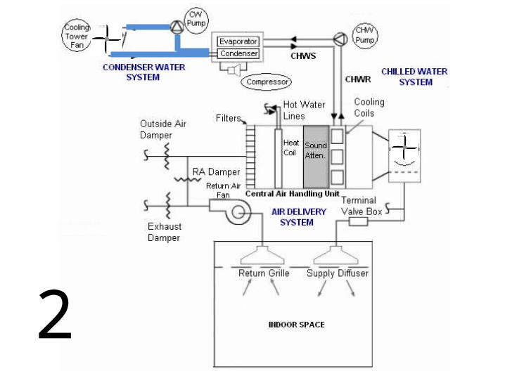
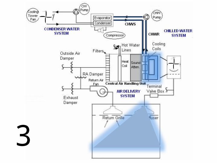
Chilled water plant
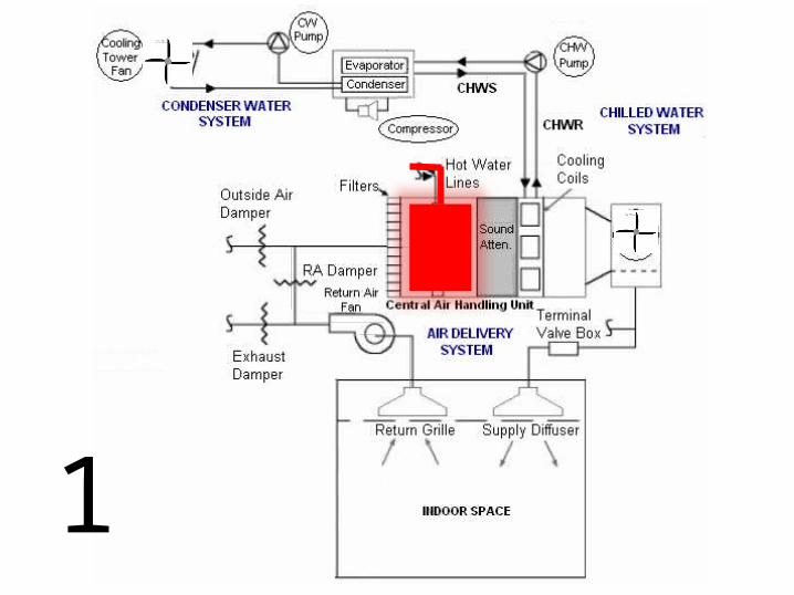
condenser water system (heat rejection system)
air-delivery system
Sub systems of centralized AC
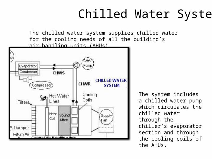
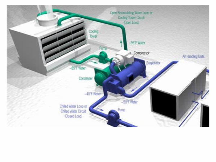
Chilled Water System The chilled water system supplies chilled water for the cooling needs of all the building’s air-handling units (AHUs)
The system includes a chilled water pump which circulates the chilled water through the chiller’s evaporator section and through the cooling coils of the AHUs.
Condenser Water System
refrigeration system must also reject the heat that it removes.
There are two options for heat rejection:
1) air cooled &2) water cooled
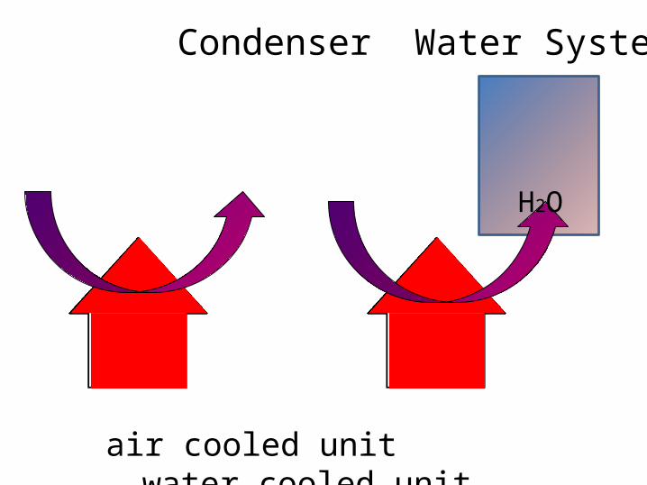
Condenser Water System
air cooled unit water cooled unit
H2O
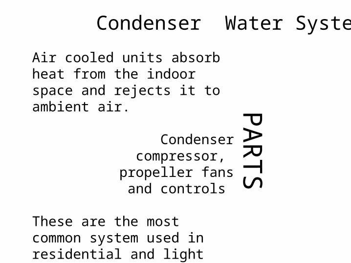
Air cooled units absorb heat from the indoor space and rejects it to ambient air.
Condensercompressor,
propeller fans and controls
These are the most common system used in residential and light commercial applications.
PARTS
Condenser Water System
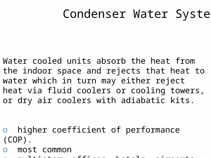
Water cooled units absorb the heat from the indoor space and rejects that heat to water which in turn may either reject heat via fluid coolers or cooling towers, or dry air coolers with adiabatic kits.
o higher coefficient of performance (COP).o most common o multistory offices, hotels, airports and shopping complexes.
Condenser Water System
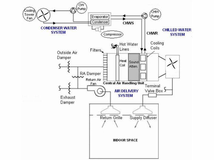
Air Delivery System
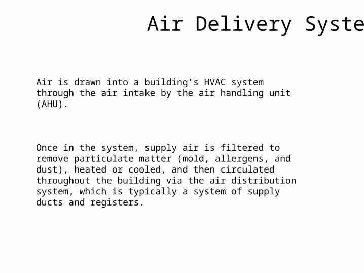
Air is drawn into a building’s HVAC system through the air intake by the air handling unit (AHU).
Once in the system, supply air is filtered to remove particulate matter (mold, allergens, and dust), heated or cooled, and then circulated throughout the building via the air distribution system, which is typically a system of supply ducts and registers.
water
air
1
2
3
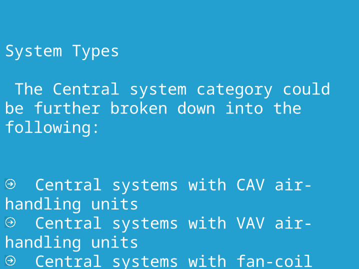
System Types
The Central system category could be further broken down into the following:
Central systems with CAV air-handling units
Central systems with VAV air-handling units
Central systems with fan-coil units (All- Water systems).
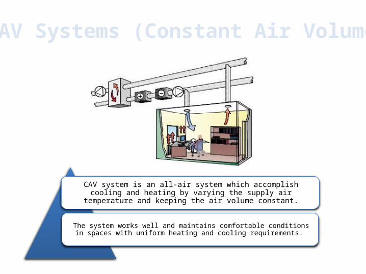
CAV Systems (Constant Air Volume)
CAV system is an all-air system which accomplish cooling and heating by varying the supply air temperature and keeping the air
volume constant.
The system works well and maintains comfortable conditions in spaces with uniform heating and cooling requirements.
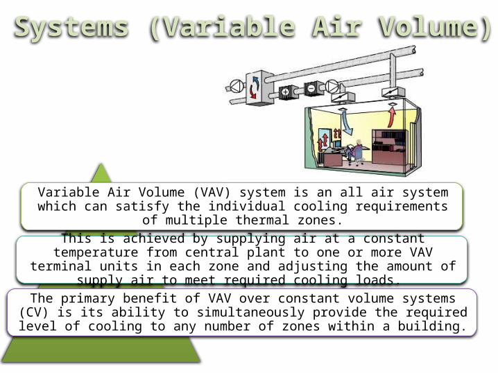
Variable Air Volume (VAV) system is an all air system which can satisfy the individual cooling requirements of multiple thermal
zones.
This is achieved by supplying air at a constant temperature from central plant to one or more VAV terminal units in each zone and
adjusting the amount of supply air to meet required cooling loads.
The primary benefit of VAV over constant volume systems (CV) is its ability to simultaneously provide the required level of cooling to any
number of zones within a building.
VAV Systems (Variable Air Volume)
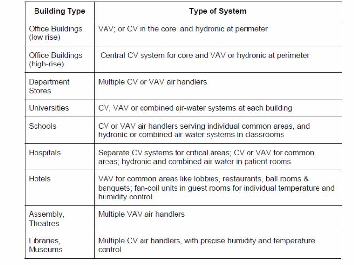
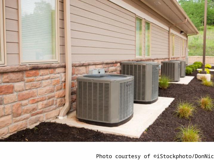
Photo courtesy of ©iStockphoto/DonNichols.
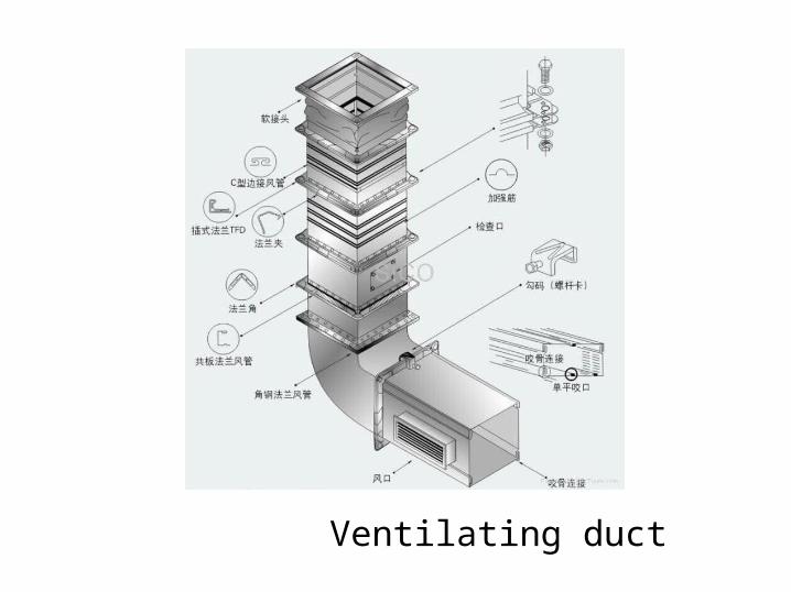
Ventilating duct
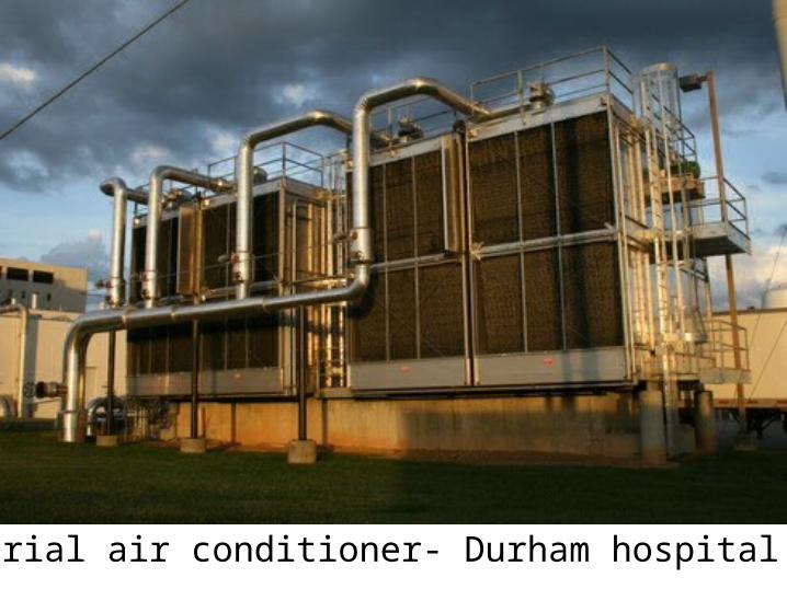
Industrial air conditioner- Durham hospital
AHUAIR HANDLING UNIT
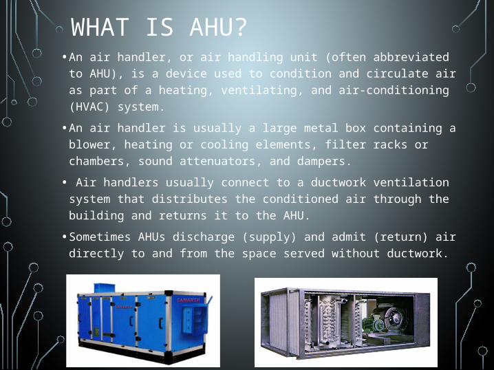
WHAT IS AHU?• An air handler, or air handling unit (often abbreviated to
AHU), is a device used to condition and circulate air as part of a heating, ventilating, and air-conditioning (HVAC) system.
• An air handler is usually a large metal box containing a blower, heating or cooling elements, filter racks or chambers, sound attenuators, and dampers.
• Air handlers usually connect to a ductwork ventilation system that distributes the conditioned air through the building and returns it to the AHU.
• Sometimes AHUs discharge (supply) and admit (return) air directly to and from the space served without ductwork.
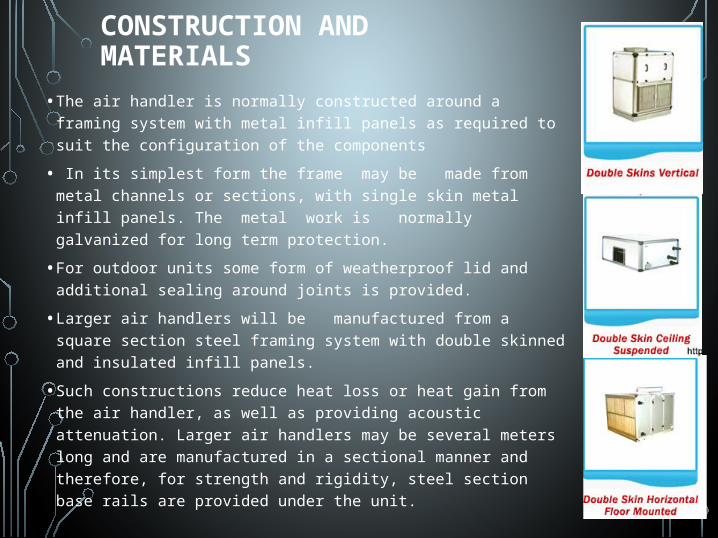
CONSTRUCTION AND MATERIALS
• The air handler is normally constructed around a framing system with metal infill panels as required to suit the configuration of the components
• In its simplest form the frame may be made from metal channels or sections, with single skin metal infill panels. The metal work is normally galvanized for long term protection.
• For outdoor units some form of weatherproof lid and additional sealing around joints is provided.
• Larger air handlers will be manufactured from a square section steel framing system with double skinned and insulated infill panels.
• Such constructions reduce heat loss or heat gain from the air handler, as well as providing acoustic attenuation. Larger air handlers may be several meters long and are manufactured in a sectional manner and therefore, for strength and rigidity, steel section base rails are provided under the unit.

COMPONENTS
• An air handling unit; air flow is• from the right to left in this case.• Some AHU components shown are• 1 – Supply duct• 2 – Fan compartment• 3 – Vibration isolator ('flex joint')• 4 – Heating and/or cooling coil• 5 – Filter compartment• 6 – Mixed (recirculated + outside) air
duct
WORKING
• Fresh air mixes with re circulated air in mixing chamber where amount of fresh air and recirculated air is adjusted by the dampers
• Filters remove the dirt particles from the air
• Cooling coil -from AC compressor the refrigerant passes through cooling coil and goes back so air coming to cooling coil gets reduced in temperature as per setting
• Heating coil-steam inlet and return used in cold areas
• Humidifiers-to humidify dry air
• Fan – sucks air and blows it to the accomodation
COMPONENTS
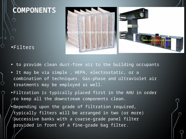
• Filters
• to provide clean dust-free air to the building occupants
• It may be via simple , HEPA, electrostatic, or a combination of techniques. Gas-phase and ultraviolet air treatments may be employed as well.
• Filtration is typically placed first in the AHU in order to keep all the downstream components clean.
• Depending upon the grade of filtration required, typically filters will be arranged in two (or more) successive banks with a coarse-grade panel filter provided in front of a fine-grade bag filter.
• Heating and/or cooling elements
• Air handlers may need to provide heating, cooling, or both to change the supply air temperature, and humidity level depending on the location and the application.
• Such conditioning is provided by heat exchanger coil(s) within the AHU air stream, such coils may be direct or indirect in relation to the medium providing the heating or cooling effect.
• Coils are typically manufactured from copper for the tubes, with copper or aluminum fins to aid heat transfer.
• If dehumidification is required, then the cooling coil is employed to over-cool so condensation occurs. A heater coil placed after the cooling coil re-heats the air to the desired supply temperature. This has the effect of reducing the relative humidity level of the supply air.
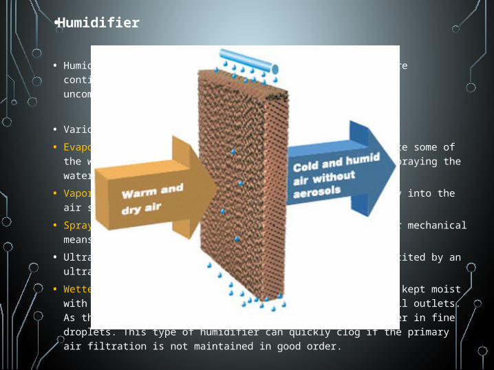
• Humidifier
• Humidification is often necessary in colder climates where continuous heating will make the air drier, resulting in uncomfortable air quality
• Various types of humidification may be used:
• Evaporative: dry air blown over a reservoir will evaporate some of the water. The rate of evaporation can be increased by spraying the water onto baffles in the air stream.
• Vaporizer: steam or vapor from a boiler is blown directly into the air stream.
• Spray mist: water is diffused either by a nozzle or other mechanical means into fine droplets and carried by the air.
• Ultrasonic: A tray of fresh water in the airstream is excited by an ultrasonic device forming a fog or water mist.
• Wetted medium: A fine fibrous medium in the airstream is kept moist with fresh water from a header pipe with a series of small outlets. As the air passes through the medium it entrains the water in fine droplets. This type of humidifier can quickly clog if the primary air filtration is not maintained in good order.
•Mixing chamber
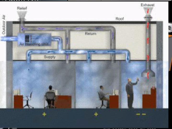
• In order to maintain indoor air quality, air handlers commonly have provisions to allow the introduction of outside air into, and the exhausting of air from the building.
• In temperate climates, mixing the right amount of cooler outside air with warmer return air can be used to approach the desired supply air temperature. A mixing chamber is therefore used which has dampers controlling the ratio between the return, outside, and exhaust air.
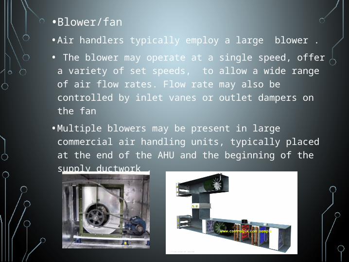
• Blower/fan
• Air handlers typically employ a large blower .
• The blower may operate at a single speed, offer a variety of set speeds, to allow a wide range of air flow rates. Flow rate may also be controlled by inlet vanes or outlet dampers on the fan
• Multiple blowers may be present in large commercial air handling units, typically placed at the end of the AHU and the beginning of the supply ductwork .
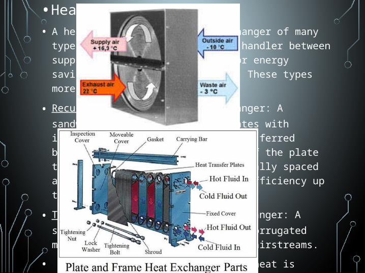
•Heat recovery device• A heat recovery device heat exchanger of many types,
may be fitted to the air handler between supply and extract airstreams for energy savings and increasing capacity. These types more commonly include for:
• Recuperator, or Plate Heat exchanger: A sandwich of plastic or metal plates with interlaced air paths. Heat is transferred between airstreams from one side of the plate to the other. The plates are typically spaced at 4 to 6mm apart. Heat recovery efficiency up to 70%.
• Thermal Wheel, or Rotary heat exchanger: A slowly rotating matrix of finely corrugated metal, operating in both opposing airstreams.
• When the AHU is in heating mode, heat is absorbed as air passes through the matrix in the exhaust airstream, during one half rotation, and released during the second half rotation into the supply airstream.
• When the AHUis in cooling mode, heat is released as air passes through the matrix in the exhaust airstream, during one half rotation, and absorbed during the second half rotation into the supply airstream. Heat recovery efficiency up to 85%.
• Controls
• Controls are necessary to regulate every aspect of an air handler, such as:
• flow rate of air,
• supply air temperature,
• mixed air temperature, humidity, air quality.
• Common control components include temperature sensors, humidity sensors, sail switches, actuators, motors, and controllers.
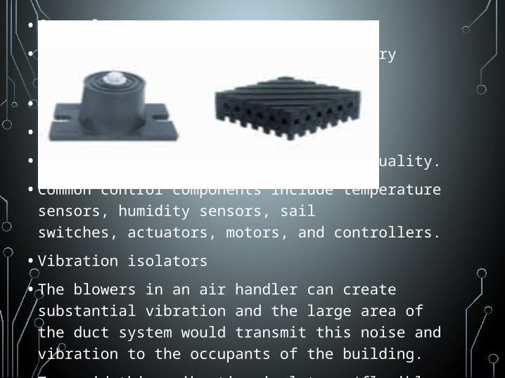
• Vibration isolators
• The blowers in an air handler can create substantial vibration and the large area of the duct system would transmit this noise and vibration to the occupants of the building.
• To avoid this, vibration isolators (flexible sections) are normally inserted into the duct immediately before and after the air handler and often also between the fan compartment and the rest of the AHU. The rubberized canvas-like material of these sections allows the air handler components to vibrate without transmitting this motion to the attached ducts.
TYPES OF AHU SYSTEMS
• single-zone• Multizone• dual-duct• Reheat• variable air volume systems
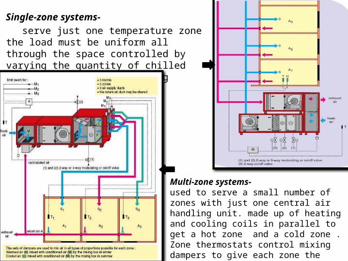
Single-zone systems- serve just one temperature zone the load
must be uniform all through the space controlled by varying the quantity of chilled water or refrigerant, adding reheat, adjusting dampers
Multi-zone systems-used to serve a small number of zones with just one central air handling unit. made up of heating and cooling coils in parallel to get a hot zone and a cold zone . Zone thermostats control mixing dampers to give each zone the right supply temperature
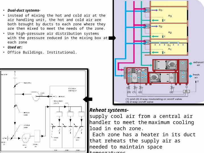
• Dual-duct systems- • instead of mixing the hot and cold air at the air
handling unit, the hot and cold air are both brought by ducts to each zone where they are then mixed to meet the needs of the zone.
• Use high-pressure air distribution systems with the pressure reduced in the mixing box at each zone
• Used at:• Office Buildings. Institutional.
Reheat systems- supply cool air from a central air handler to meet the maximum cooling load in each zone. Each zone has a heater in its duct that reheats the supply air as needed to maintain space temperatures. constant volume systems
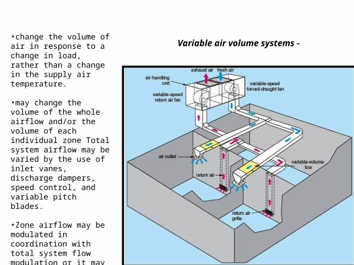
•change the volume of air in response to a change in load, rather than a change in the supply air temperature.
•may change the volume of the whole airflow and/or the volume of each individual zone Total system airflow may be varied by the use of inlet vanes, discharge dampers, speed control, and variable pitch blades.
•Zone airflow may be modulated in coordination with total system flow modulation or it may be varied by passing the excess flow right to the return air system with no variation in total system flow. •Used at:•larger office buildings.
Variable air volume systems -
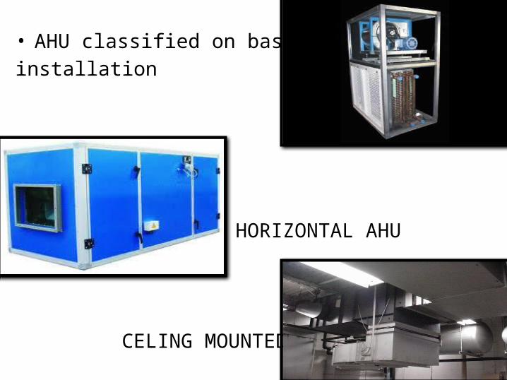
• AHU classified on basis of installation VERTICAL AHU
HORIZONTAL AHU
CELING MOUNTED AHU
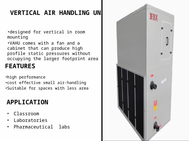
VERTICAL AIR HANDLING UNITS
•designed for vertical in room mounting•VAHU comes with a fan and a cabinet that can produce high profile static pressures without occupying the larger footprint area
FEATURES
•high performance•cost effective small air-handling •Suitable for spaces with less area
APPLICATION
• Classroom• Laboratories• Pharmaceutical labs
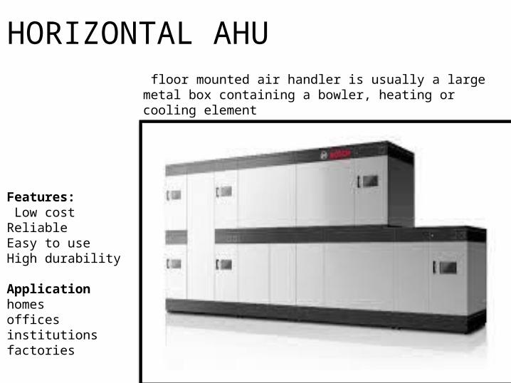
HORIZONTAL AHU
Features: Low costReliableEasy to useHigh durability
Applicationhomesofficesinstitutionsfactories
floor mounted air handler is usually a large metal box containing a bowler, heating or cooling element
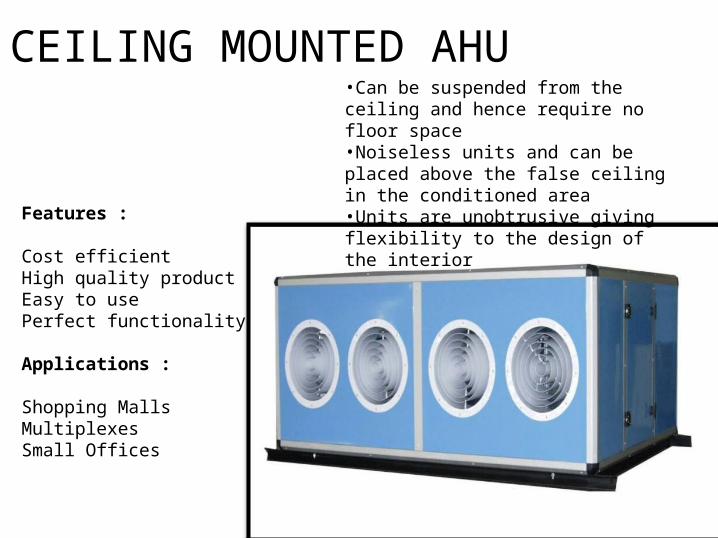
CEILING MOUNTED AHU•Can be suspended from the ceiling and hence require no floor space•Noiseless units and can be placed above the false ceiling in the conditioned area•Units are unobtrusive giving flexibility to the design of the interiorFeatures :
Cost efficientHigh quality productEasy to usePerfect functionality
Applications :
Shopping MallsMultiplexesSmall Offices
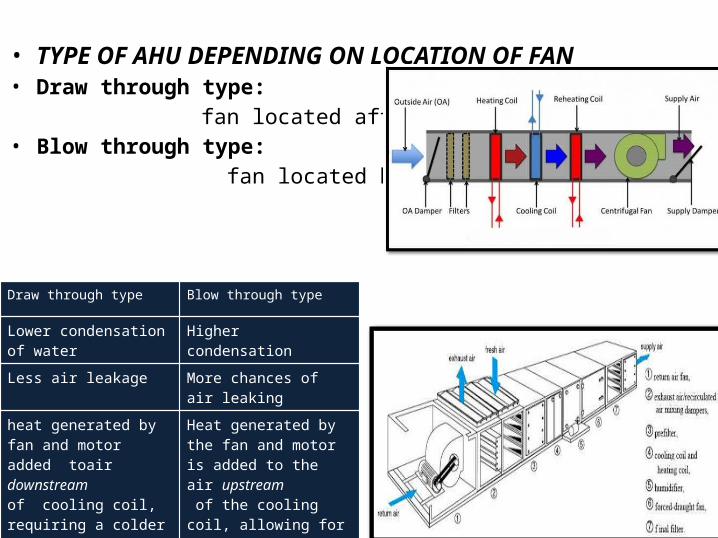
• TYPE OF AHU DEPENDING ON LOCATION OF FAN• Draw through type: fan located after cooling coil• Blow through type: fan located before cooling coil
Draw through type Blow through type
Lower condensation of water
Higher condensation
Less air leakage More chances of air leaking
heat generated by fan and motor added toair downstreamof cooling coil, requiring a colder leaving-coil temperature to achieve a desired supply-air temperature
Heat generated by the fan and motor is added to the air upstream of the cooling coil, allowing for a warmer leaving-coil temperature to achieve a desired supply-air temperature
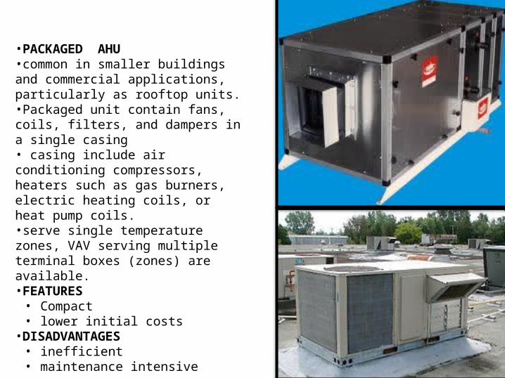
•PACKAGED AHU•common in smaller buildings and commercial applications, particularly as rooftop units. •Packaged unit contain fans, coils, filters, and dampers in a single casing• casing include air conditioning compressors, heaters such as gas burners, electric heating coils, or heat pump coils. •serve single temperature zones, VAV serving multiple terminal boxes (zones) are available. •FEATURES• Compact • lower initial costs•DISADVANTAGES• inefficient • maintenance intensive
ADVANTAGES• Modular construction and wide selection of air handling unit
sizes• Wide application range • Low energy consumption• Low risk of condensation : air tight• Easy installation and adaptability to building condition• Easy maintenance: hygienically friendly
DISADVANTAGES• AHU is physically large and requires careful planning in terms
of a suitable location. • The space required for ducting and the corresponding holes
through building fabric require careful co-ordination with builders and other mechanical services within the room.
• Rooms with variable or moving sources of heat gain such solar gain traversing around the room require sophisticated duct work and controls. Zone heaters may have to be incorporated into duct branches.
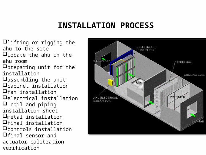
lifting or rigging the ahu to the site locate the ahu in the ahu roompreparing unit for the installationassembling the unitcabinet installation fan installationelectrical installation coil and piping installation sheetmetal installationfinal installationcontrols installation final sensor and actuator calibration verification
INSTALLATION PROCESS
• MARKET RATE • GEA Group, Germany • Carrier Corporation, New Jersey • Daikin Industries, Japan • Johnson Controls, U S• Rheem, U S• Trane, U S• ECE UK Ltd
• SOME INDIAN BRANDS• Zeco, delhi • Blow-Tech Engineers, Mumbai• Axenic Systems, Mumbai• Poly extrusions (india) private limited
FAN-COIL UNIT
FAN COIL UNIT
• It part of an HVAC system found in residential, commercial, and industrial buildings.
• A simple device consisting of a heating or cooling coil and fan.
• Used to control the temperature in the space where it is installed, or serve multiple spaces.
• It is controlled either by a manual on/off switch or by thermostat.
• Fan coil units are more economical to install than ducted or central heating systems with air handling units.
• They can be noisy because the fan is within the same space.
DESIGN
• A fan coil unit may be concealed or exposed within the room or area that it serves.
• An exposed fan coil unit may be wall mounted, freestanding or ceiling mounted.
• It typically include an appropriate enclosure to protect and conceal the fan coil unit itself.
• Return air grille and supply air diffuser set into that enclosure to distribute the air.
• A concealed fan coil unit will typically be installed within an accessible ceiling void or services zone.
• The return air grille and supply air diffuser will be ducted to and from the fan coil unit.
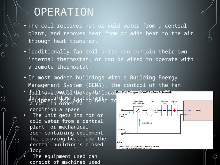
OPERATION• The coil receives hot or cold water from a central plant, and
removes heat from or adds heat to the air through heat transfer.
• Traditionally fan coil units can contain their own internal thermostat, or can be wired to operate with a remote thermostat.
• In most modern buildings with a Building Energy Management System (BEMS), the control of the fan coil unit will be by a local digital controller. equipment for adding heat to the building's water.
• Fan coil units circulate hot or cold water through a coil in order to condition a space.
• The unit gets its hot or cold water from a central plant, or mechanical room containing equipment for removing heat from the central building's closed-loop.
• The equipment used can consist of machines used to remove heat and
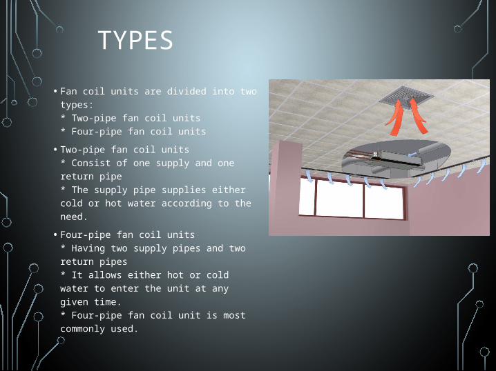
• Fan coil units are divided into two types:* Two-pipe fan coil units* Four-pipe fan coil units
• Two-pipe fan coil units* Consist of one supply and one return pipe* The supply pipe supplies either cold or hot water according to the need.
• Four-pipe fan coil units* Having two supply pipes and two return pipes* It allows either hot or cold water to enter the unit at any given time.* Four-pipe fan coil unit is most commonly used.
TYPES

COMPARISON
CentralizedVs
Decentralized
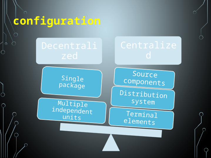
Decentralized
Centralized
Terminal elements
Distribution system
Source components
Multiple independent units
Single package
configuration
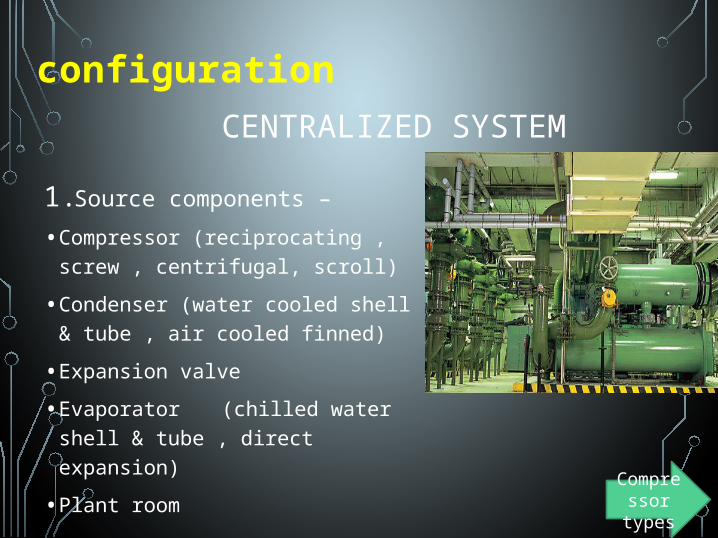
CENTRALIZED SYSTEM
1. Source components –
• Compressor (reciprocating , screw , centrifugal, scroll)
• Condenser (water cooled shell & tube , air cooled finned)
• Expansion valve
• Evaporator (chilled water shell & tube , direct expansion)
• Plant room
configuration
Compressor types
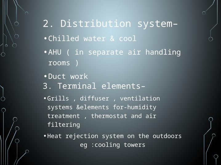
2. Distribution system–
• Chilled water & cool
• AHU ( in separate air handling rooms )
• Duct work
3. Terminal elements–
• Grills , diffuser , ventilation systems &elements for-humidity treatment , thermostat and air filtering
• Heat rejection system on the outdoors eg :cooling towers
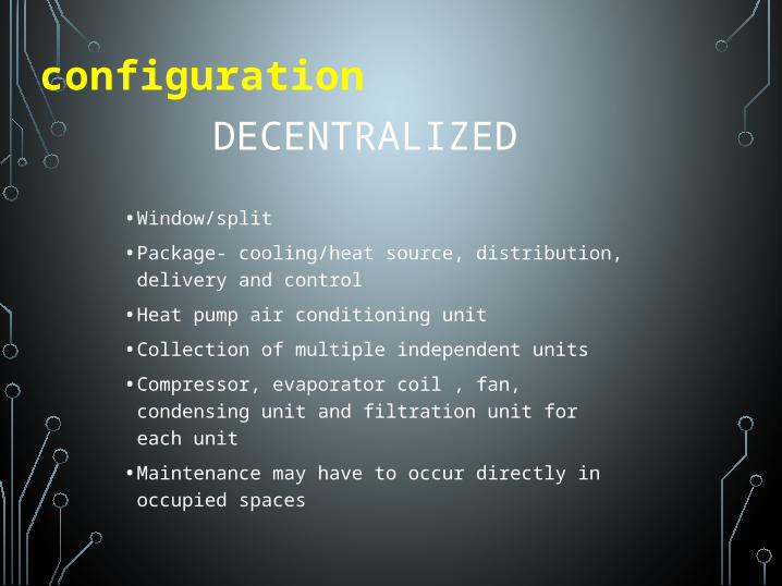
DECENTRALIZED
configuration
• Window/split
• Package- cooling/heat source, distribution, delivery and control
• Heat pump air conditioning unit
• Collection of multiple independent units
• Compressor, evaporator coil , fan, condensing unit and filtration unit for each unit
• Maintenance may have to occur directly in occupied spaces
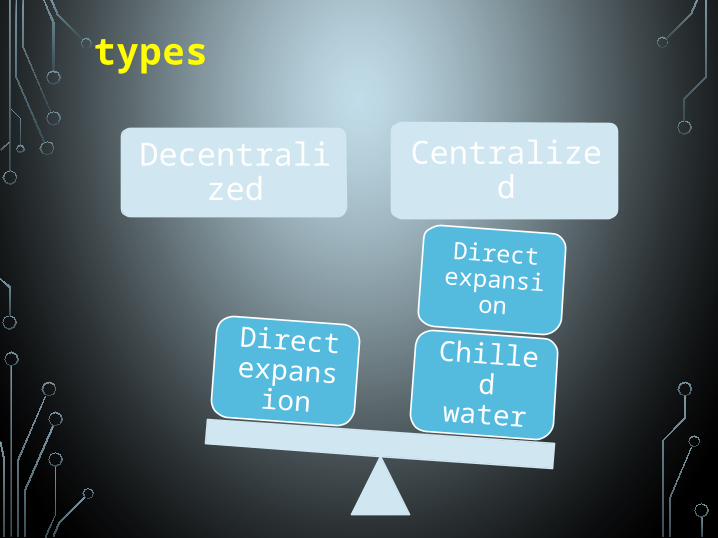
Decentralized
Centralized
Chilled water
Direct expansio
nDirect
expansion
types
types
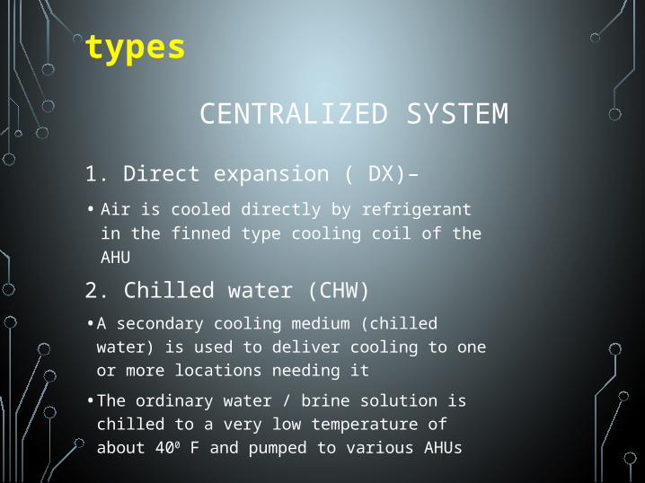
1. Direct expansion ( DX)–
• Air is cooled directly by refrigerant in the finned type cooling coil of the AHU
CENTRALIZED SYSTEM
2. Chilled water (CHW)
• A secondary cooling medium (chilled water) is used to deliver cooling to one or more locations needing it
• The ordinary water / brine solution is chilled to a very low temperature of about 400 F and pumped to various AHUs
types
DECENTRALIZED
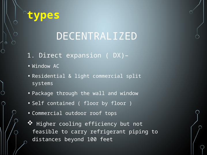
1. Direct expansion ( DX)–
• Window AC
• Residential & light commercial split systems
• Package through the wall and window
• Self contained ( floor by floor )
• Commercial outdoor roof tops
Higher cooling efficiency but not feasible to carry refrigerant piping to distances beyond 100 feet
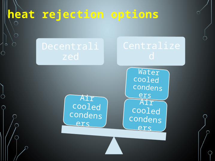
Decentralized
Centralized
Air cooled
condensers
Water cooled
condensers Air
cooled condens
ers
heat rejection options
CENTRALIZED SYSTEM
heat rejection options
1. Air cooled
• Uses finned tube coil condenser
• Refrigerant flows through the refrigerant piping from evaporator to condenser
• When refrigerant flows in the piping its pressure drops
• So the length of refrigeration tubing and the distance between the condenser and evaporator should be kept minimum
2. Water cooled
• Uses shell and tube type
• Cooling water is pumped from tubes of the cooling towers at a high pressure
• So it is easy to carry long distances
• The losses in the pressure of water accommodated by the sufficient capacity of the pump, which has low capital and running cost
• Can be placed at any distance from the cooling equipment
• For cooling loads between 100-125 tons- air cooled is used
• Above 200 tons- water cooled is suitable
• Between 100-200 tons, depends on the owner
DECENTRALIZED SYSTEM
heat rejection options
1. Air cooled
• Air cooled condensers used to expel heat
• Generally kept very close to the evaporator units
• For smaller systems- length=30-40 ft
• For large systems- upto 3 to 4 times of smaller ones.
CENTRALIZED SYSTEMapplications
1. Hotels
2. Theatres
3. Airports
4. Shopping malls
• The largest capacity of chiller available in market-2000 tons
• Multiple chillers are installed to cater for higher loads
• Often a “hybrid system”, which a combination of centralized and decentralized package units is preferred.
E.g.: in a hotel- packaged unitary ACs for individual guest rooms
Roof top units for meeting rooms/restaurants
Central plant system for lobby, corridors and other common spaces
DECENTRALIZED SYSTEMapplications
1. More appropriate for low to mid rise buildings
2. In places where large number of spaces are unoccupied
3. Capacity range from .5 tons- 130 tons (for roof top package units)
4. Can be matched up to separate interior spaces in a large building (advantage)
5. Offer high flexibility in meeting the requirements of different working hours and special design conditions
CENTRALIZED SYSTEMefficiencies
1. Improved efficiency and lower first cost by sharing load capacity across an entire building
2. Chiller efficiency is typically defined in terms of kW/ton and its coefficient of performance(COP)
3. The COP= (output Btu)/ (Input Btu)
4. Reciprocating chillers have a peak load power requirement of 1.02- 1.3 kW/ton
5. Screw chillers - 0 .5- 0.7 kW/ton
6. Centrifugal- most efficient at peak load and consume least power - 0.53- 0.7 kW/ton
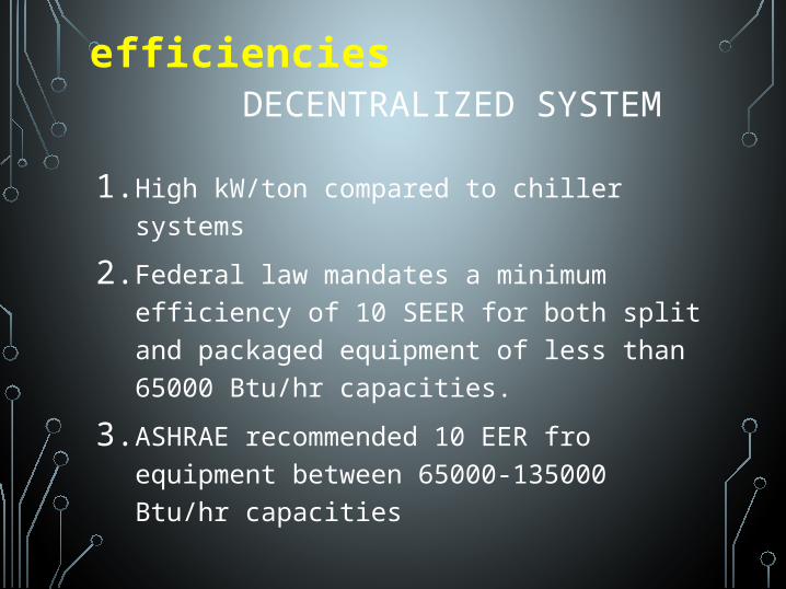
efficienciesDECENTRALIZED SYSTEM
1. High kW/ton compared to chiller systems
2. Federal law mandates a minimum efficiency of 10 SEER for both split and packaged equipment of less than 65000 Btu/hr capacities.
3. ASHRAE recommended 10 EER fro equipment between 65000-135000 Btu/hr capacities
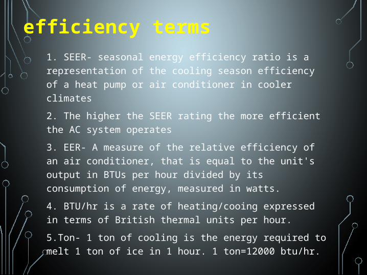
1. SEER- seasonal energy efficiency ratio is a representation of the cooling season efficiency of a heat pump or air conditioner in cooler climates
2. The higher the SEER rating the more efficient the AC system operates
3. EER- A measure of the relative efficiency of an air conditioner, that is equal to the unit's output in BTUs per hour divided by its consumption of energy, measured in watts.
4. BTU/hr is a rate of heating/cooing expressed in terms of British thermal units per hour.
5.Ton- 1 ton of cooling is the energy required to melt 1 ton of ice in 1 hour. 1 ton=12000 btu/hr.
efficiency terms
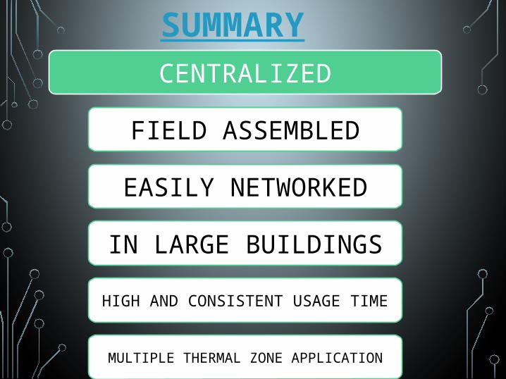
SUMMARY
CENTRALIZED
FIELD ASSEMBLED
EASILY NETWORKED
IN LARGE BUILDINGS
HIGH AND CONSISTENT USAGE TIME
MULTIPLE THERMAL ZONE APPLICATION
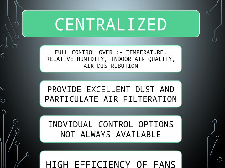
CENTRALIZEDFULL CONTROL OVER :- TEMPERATURE,
RELATIVE HUMIDITY, INDOOR AIR QUALITY, AIR DISTRIBUTION
PROVIDE EXCELLENT DUST AND PARTICULATE AIR FILTERATION
INDVIDUAL CONTROL OPTIONS NOT ALWAYS AVAILABLE
HIGH EFFICIENCY OF FANS
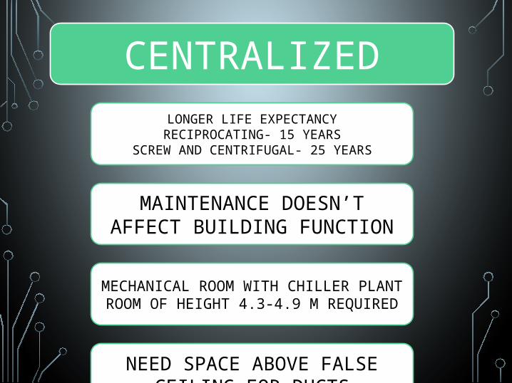
CENTRALIZEDLONGER LIFE EXPECTANCYRECIPROCATING- 15 YEARS
SCREW AND CENTRIFUGAL- 25 YEARS
MAINTENANCE DOESN’T AFFECT BUILDING FUNCTION
MECHANICAL ROOM WITH CHILLER PLANT ROOM OF HEIGHT 4.3-4.9 M REQUIRED
NEED SPACE ABOVE FALSE CEILING FOR DUCTS
CENTRALIZED
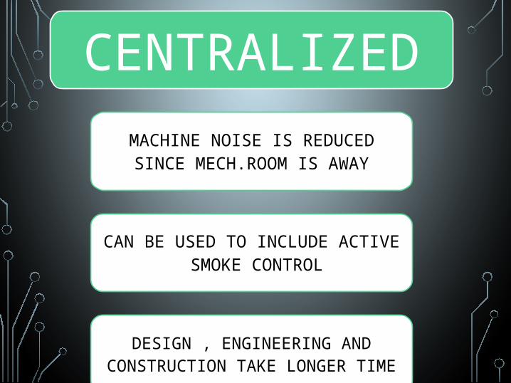
MACHINE NOISE IS REDUCED SINCE MECH.ROOM IS AWAY
CAN BE USED TO INCLUDE ACTIVE SMOKE CONTROL
DESIGN , ENGINEERING AND CONSTRUCTION TAKE LONGER
TIME
THANK YOU