centrifugal pumps learning hvac
DESCRIPTION
Centrifugal Pumps Learning HVACTRANSCRIPT
MEBS6008 Environmental Services IIhttp://www.hku.hk/bse/MEBS6008/
Fans and Pumps IDr. Sam C M Hui
Department of Mechanical EngineeringDepartment of Mechanical EngineeringThe University of Hong Kong
E-mail: cmhui@hku hkE mail: [email protected] 2010
Contents
• Centrifugal PumpsCentrifugal Pumps
• Pump Arrangements
• Matching Pumps to Systems• Matching Pumps to Systems
Centrifugal Pumps
• Centrifugal pumpg p p• Most widely used in HVAC applications, e .g.
• Hot water systems• Hot water systems• Chilled water systems
C d t t• Condenser water systems• Boiler feed and condensate return pumps
• Operation• Electric motor’s output torque => impeller’s rotation• Coupling to the pump shaft• Centrifugal force & tip speed forceg p p
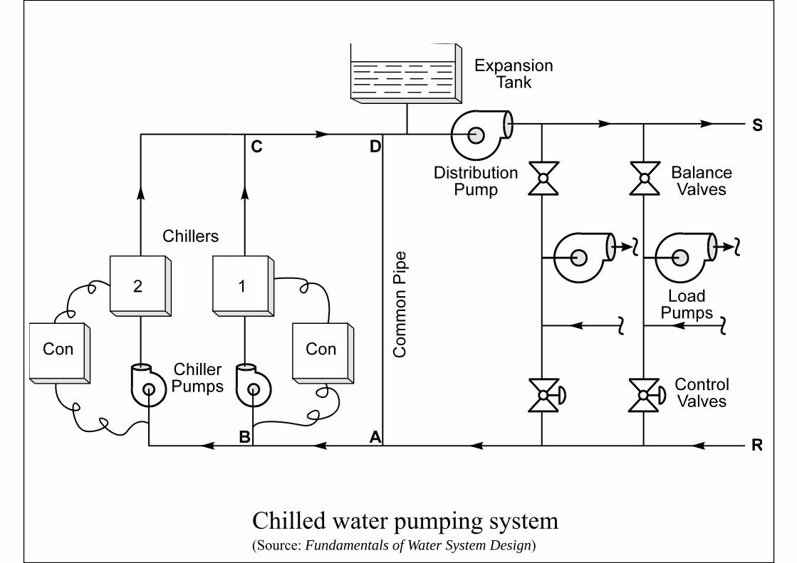
(Source: Fundamentals of Water System Design)Chilled water pumping system
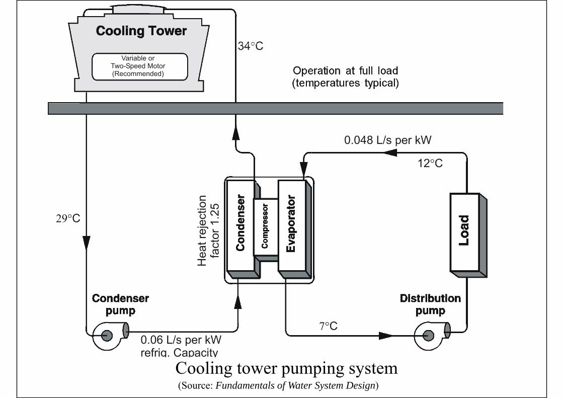
(Source: Fundamentals of Water System Design)Cooling tower pumping system
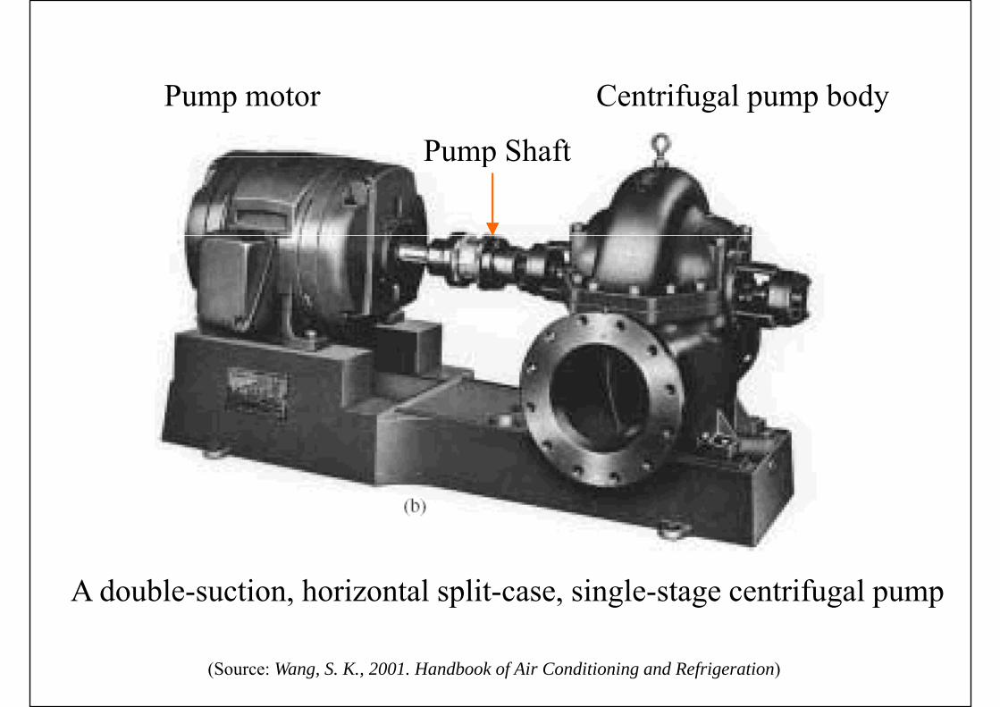
Pump motor Centrifugal pump body
Pump ShaftPump Shaft
A double-suction, horizontal split-case, single-stage centrifugal pump
(Source: Wang, S. K., 2001. Handbook of Air Conditioning and Refrigeration)

(Source: ASHRAE HVAC Systems and Equipment Handbook 2004)Typical overhung-impeller end-suction pump
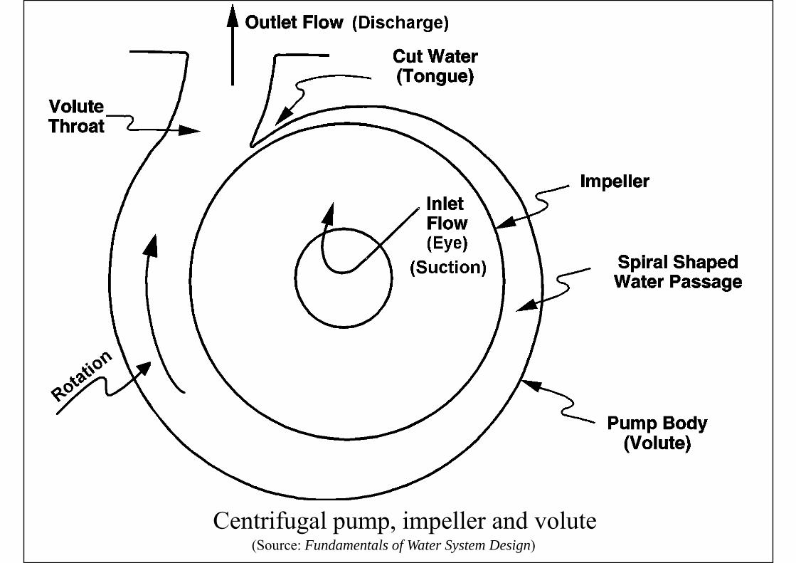
(Source: Fundamentals of Water System Design)Centrifugal pump, impeller and volute
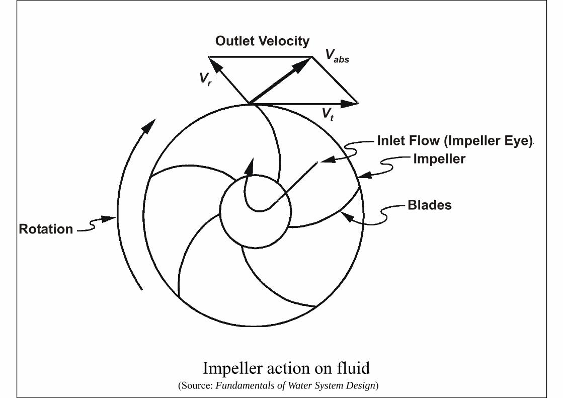
(Source: Fundamentals of Water System Design)Impeller action on fluid

(Source: Fundamentals of Water System Design)Flow pattern of impeller/volute action

Centrifugal Pumps
• Types of centrifugal pumpsTypes of centrifugal pumps• Circulator pump• Closed-couple end suction pump• Frame-mounted end suction pumpFrame mounted end suction pump• Base-mounted horizontal split case pump• Vertical inline pump• Vertical turbine single or multistage pump• Vertical turbine single or multistage pump
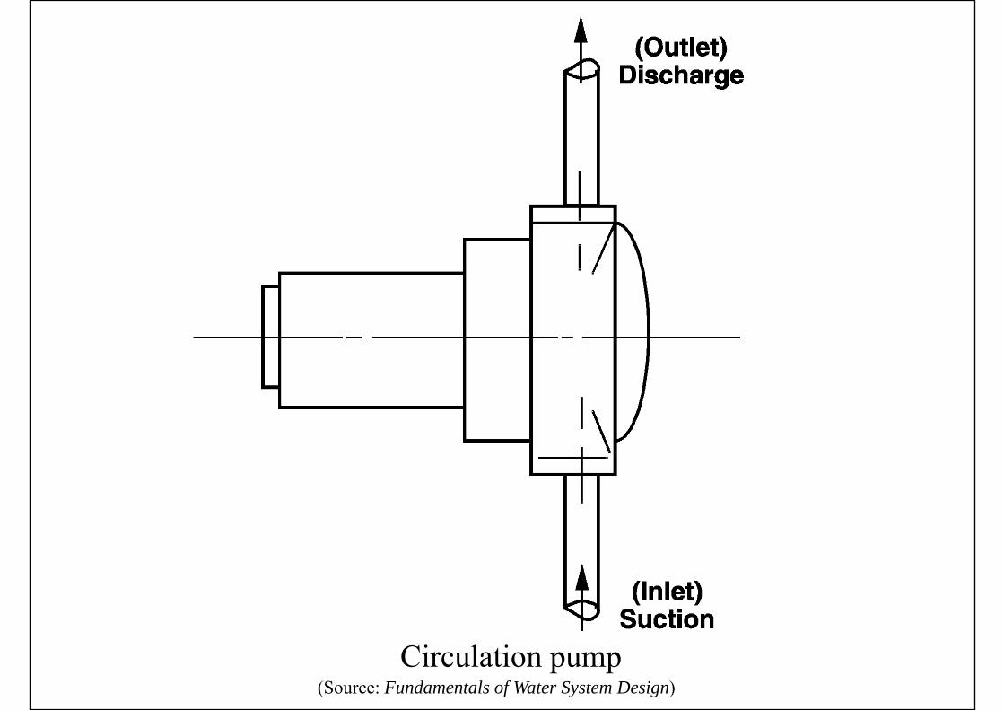
(Source: Fundamentals of Water System Design)Circulation pump
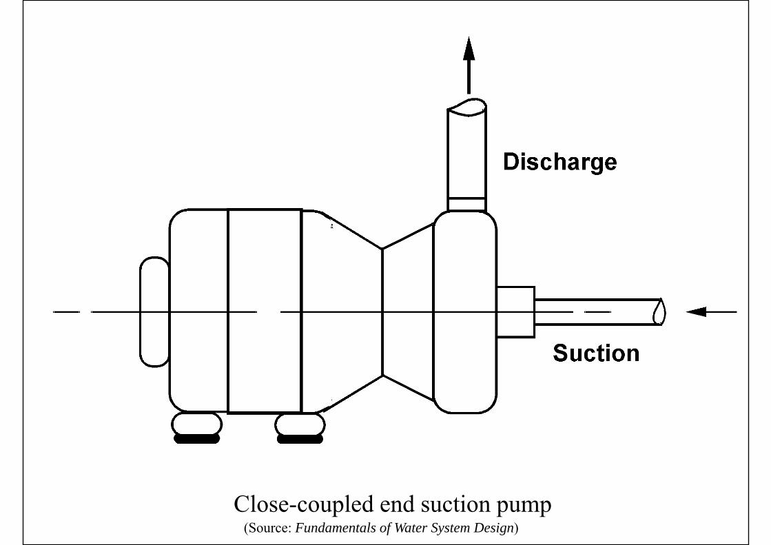
(Source: Fundamentals of Water System Design)Close-coupled end suction pump
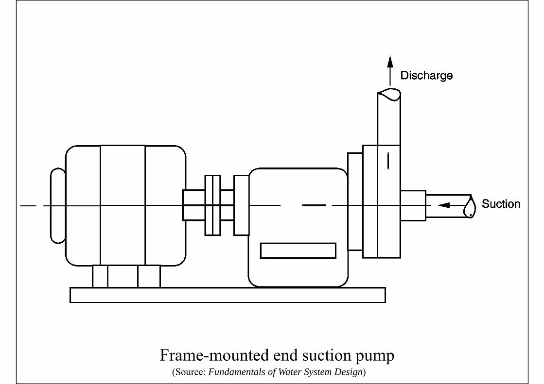
(Source: Fundamentals of Water System Design)Frame-mounted end suction pump

(Source: Fundamentals of Water System Design)Base-mounted horizontal split case pump
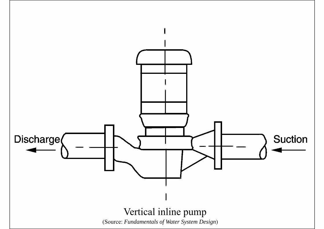
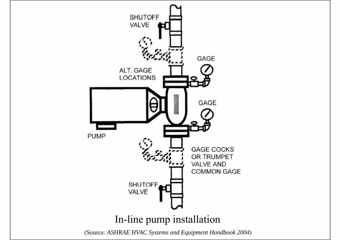
(Source: Fundamentals of Water System Design)Vertical inline pump
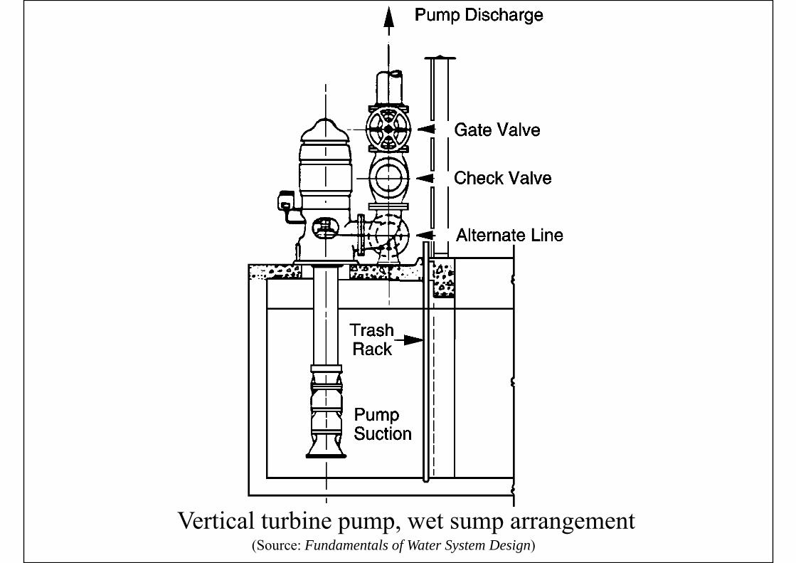
(Source: Fundamentals of Water System Design)Vertical turbine pump, wet sump arrangement

(Source: ASHRAE HVAC Systems and Equipment Handbook 2004)Base plate-mounted centrifugal pump installation
(Source: ASHRAE HVAC Systems and Equipment Handbook 2004)
In-line pump installation

Centrifugal Pumps
• Variable speed pumpsVariable speed pumps• Less expensive nowadays
• Centrifugal pump characteristics• Total pressure capacity curve• Total pressure-capacity curve
• Flat curve: applied on closed piping systems with d l i lmodulating valves
• Steep curve: usually for open piping systems (cooling towers), w/ high pressure, constant flow
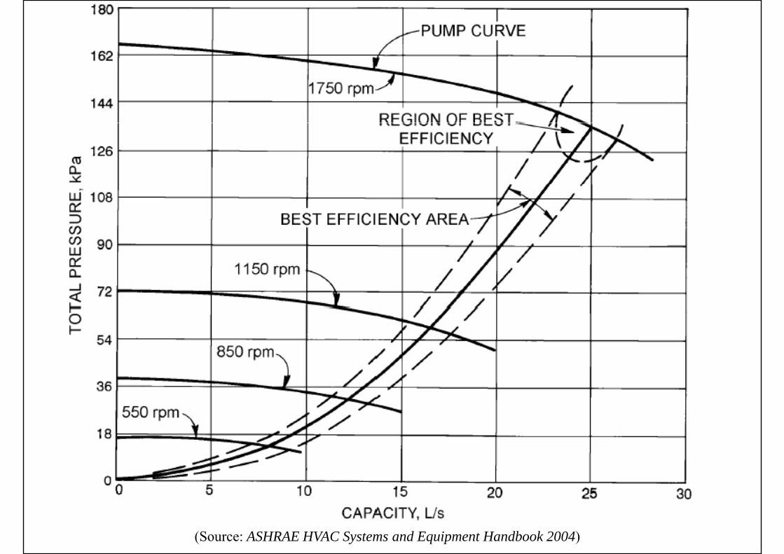
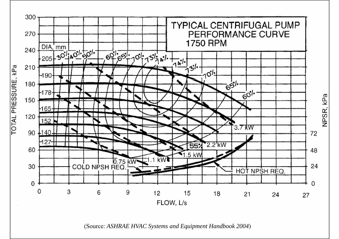
• Family of pump performance curvesy p p p
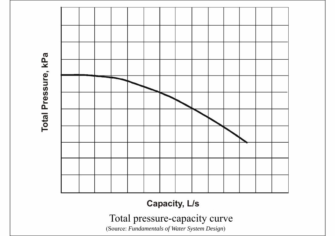
(Source: Fundamentals of Water System Design)Total pressure-capacity curve

WhWhat does this i l ?
(Source: Fundamentals of Water System Design)Flat versus steep pump curvesimply?
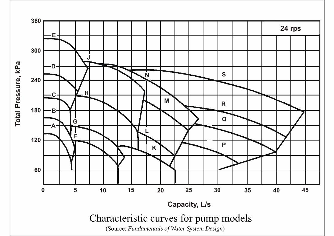
(Source: Fundamentals of Water System Design)Characteristic curves for pump models
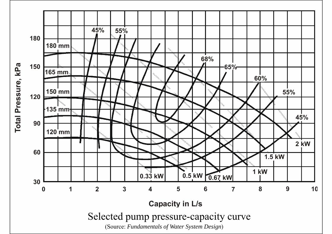
(Source: Fundamentals of Water System Design)Selected pump pressure-capacity curve
Centrifugal Pumps
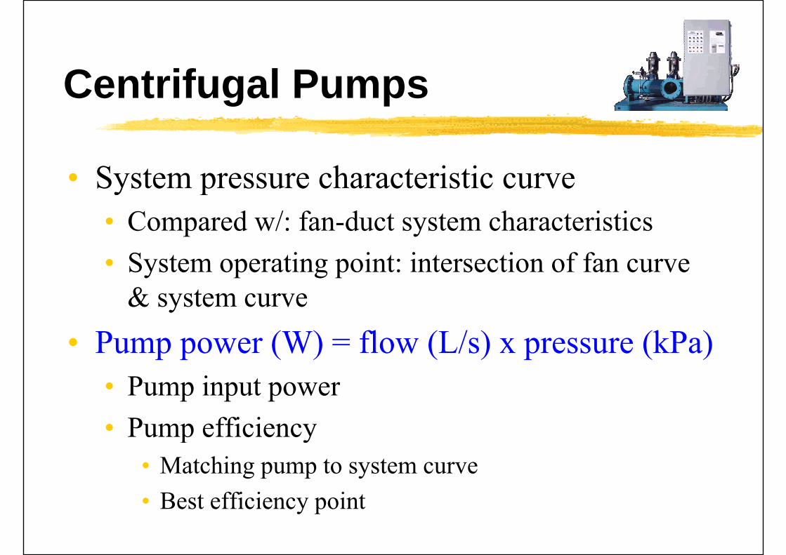
• System pressure characteristic curveSystem pressure characteristic curve• Compared w/: fan-duct system characteristics• System operating point: intersection of fan curve
& system curvey• Pump power (W) = flow (L/s) x pressure (kPa)
• Pump input power• Pump efficiencyPump efficiency
• Matching pump to system curveB ffi i i• Best efficiency point

(Source: ASHRAE HVAC Systems and Equipment Handbook 2004)

(Source: Fundamentals of Water System Design)Increase of pumping power required with pump flow
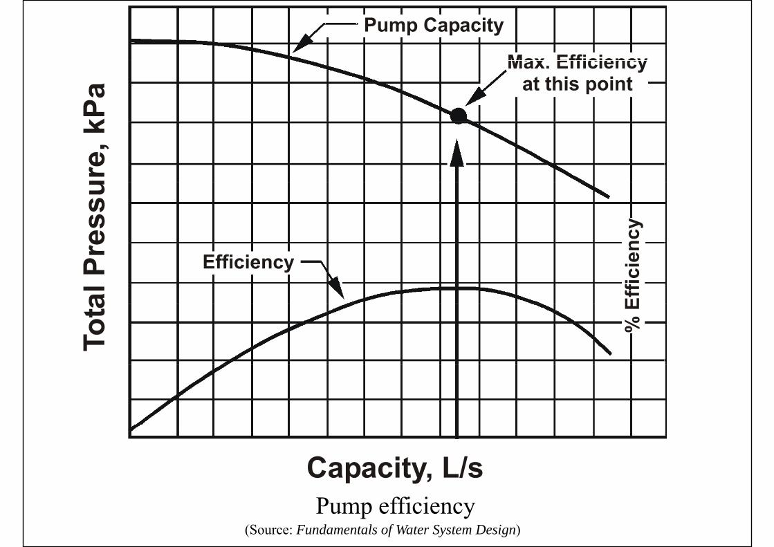
(Source: Fundamentals of Water System Design)Pump efficiency
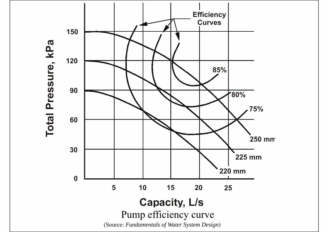
(Source: Fundamentals of Water System Design)Pump efficiency curve

Centrifugal Pumps
• Similarity relationshipsSimilarity relationships• Pump affinity laws (c.f. fan laws)
Function Speed change Impeller diameter changechange
Flow Q2 = Q1 (N2/N1) Q2 = Q1 (D2/D1)
Pressure p2 = p1 (N2/N1)2 p2 = p1 (D2/D1)2
Power P2 = P1 (N2/N1)3 P2 = P1 (D2/D1)3Power P2 P1 (N2/N1) P2 P1 (D2/D1)
Centrifugal Pumps
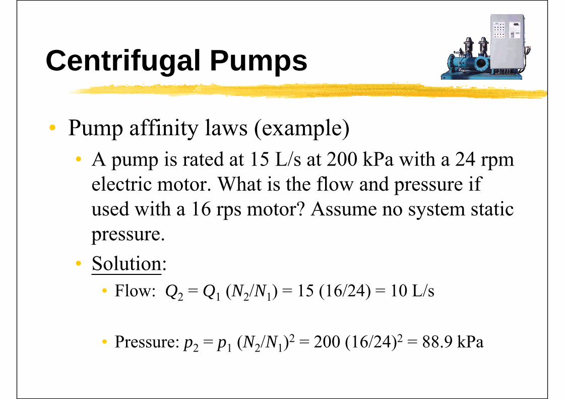
• Pump affinity laws (example)Pump affinity laws (example)• A pump is rated at 15 L/s at 200 kPa with a 24 rpm
l i Wh i h fl d ifelectric motor. What is the flow and pressure if used with a 16 rps motor? Assume no system static pressure.
• Solution:Solution:• Flow: Q2 = Q1 (N2/N1) = 15 (16/24) = 10 L/s
• Pressure: p2 = p1 (N2/N1)2 = 200 (16/24)2 = 88.9 kPa
(Source: ASHRAE HVAC Systems and Equipment Handbook 2004)
Centrifugal Pumps
• Radial thrust• Non-uniform pressure around impeller
G t t t h t ff• Greatest at shutoff• Decreases from shutoff to design capacity• Increase with overcapacity
• Net positive suction (NPS)• Net positive suction (NPS)• Cavitation: vapour pockets form in impeller
& dpassages & may cause damages• Net positive suction required (NPSR) - pumpp q ( ) p p

(Source: Fundamentals of Water System Design)Pressures on impeller causing radial thrust
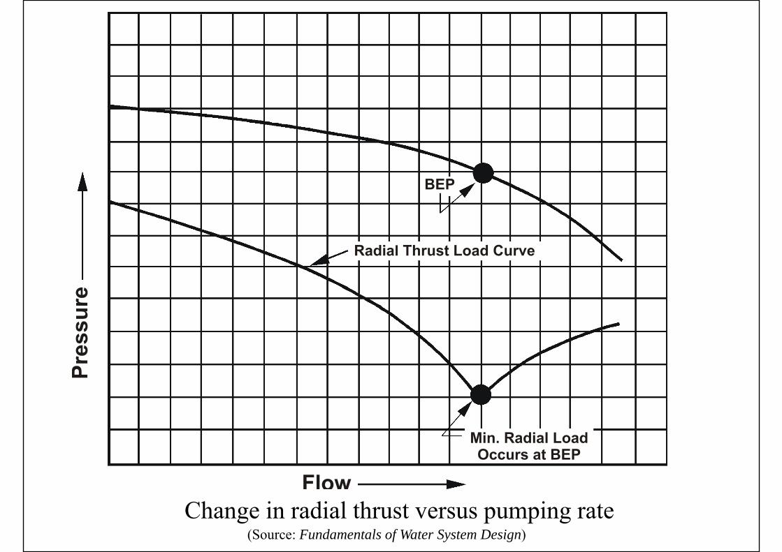
(Source: Fundamentals of Water System Design)Change in radial thrust versus pumping rate

Centrifugal Pumps
• Net positive suction available (NPSA)Net positive suction available (NPSA)• For the installation• Total useful energy above the vapour pressure at
the pump suction connectionp p• Affected by the location of expansion tank
• If NPSA < Pump’s NPSR• Cavitation noise inadequate pumping etcCavitation, noise, inadequate pumping, etc.• Avoid problem, NPSA > NPSR
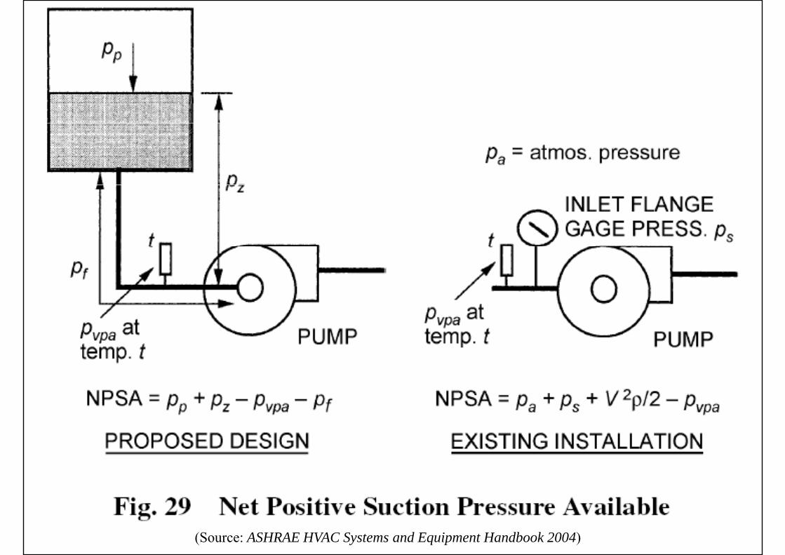
(Source: ASHRAE HVAC Systems and Equipment Handbook 2004)
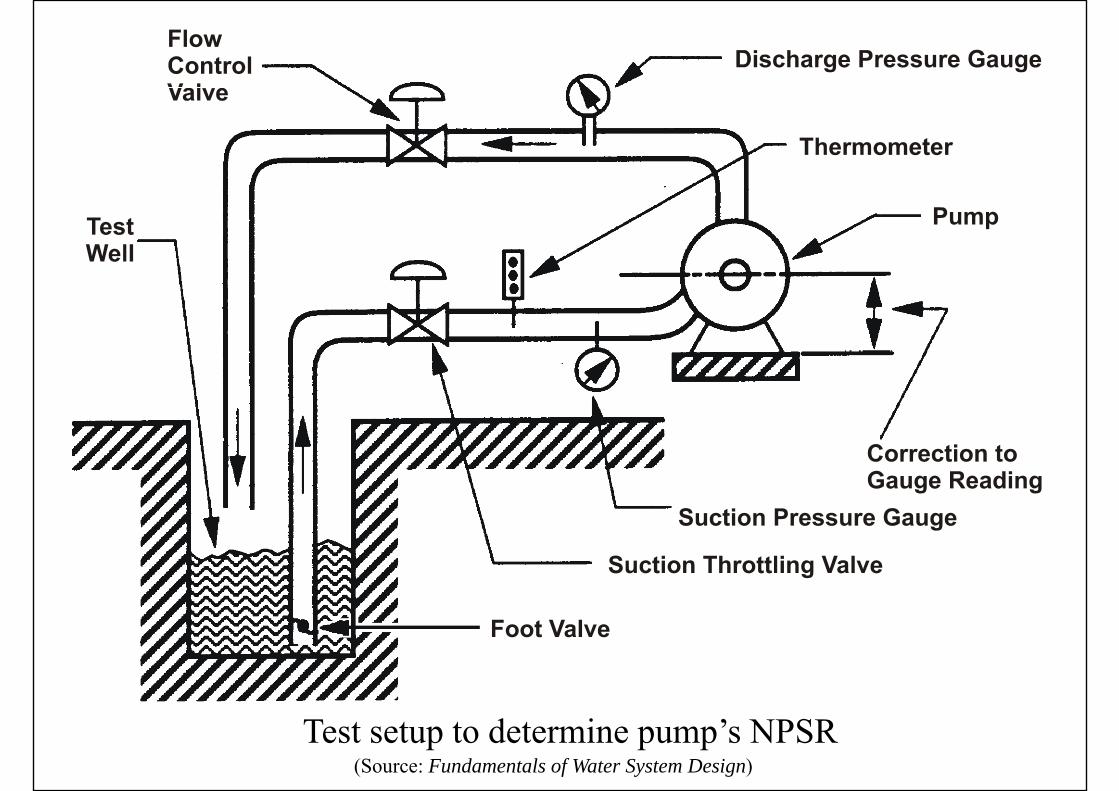
(Source: Fundamentals of Water System Design)Test setup to determine pump’s NPSR
(Source: ASHRAE HVAC Systems and Equipment Handbook 2004)
Pump Arrangements
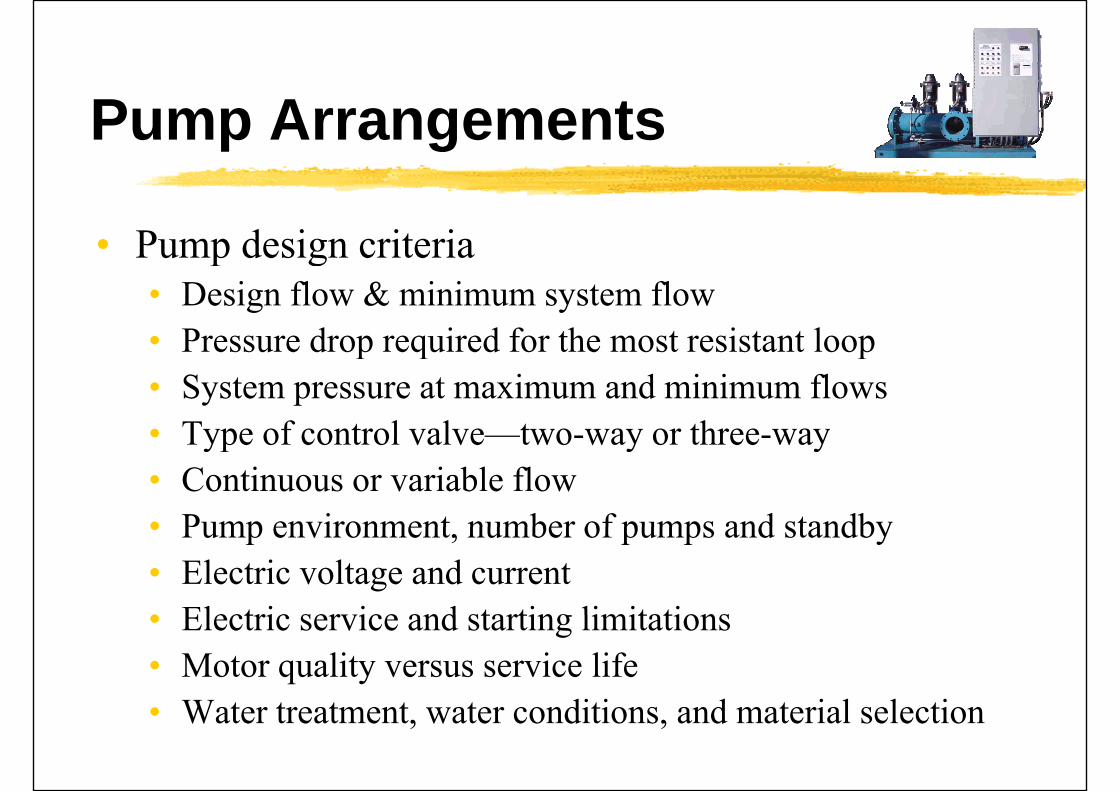
• Pump design criteriap g• Design flow & minimum system flow• Pressure drop required for the most resistant loopPressure drop required for the most resistant loop• System pressure at maximum and minimum flows• Type of control valve—two-way or three-wayType of control valve two way or three way• Continuous or variable flow• Pump environment number of pumps and standby• Pump environment, number of pumps and standby• Electric voltage and current• Electric service and starting limitations• Electric service and starting limitations• Motor quality versus service life
W t t t t t diti d t i l l ti• Water treatment, water conditions, and material selection

(Source: Fundamentals of Water System Design)Pump selection process
Pump Arrangements
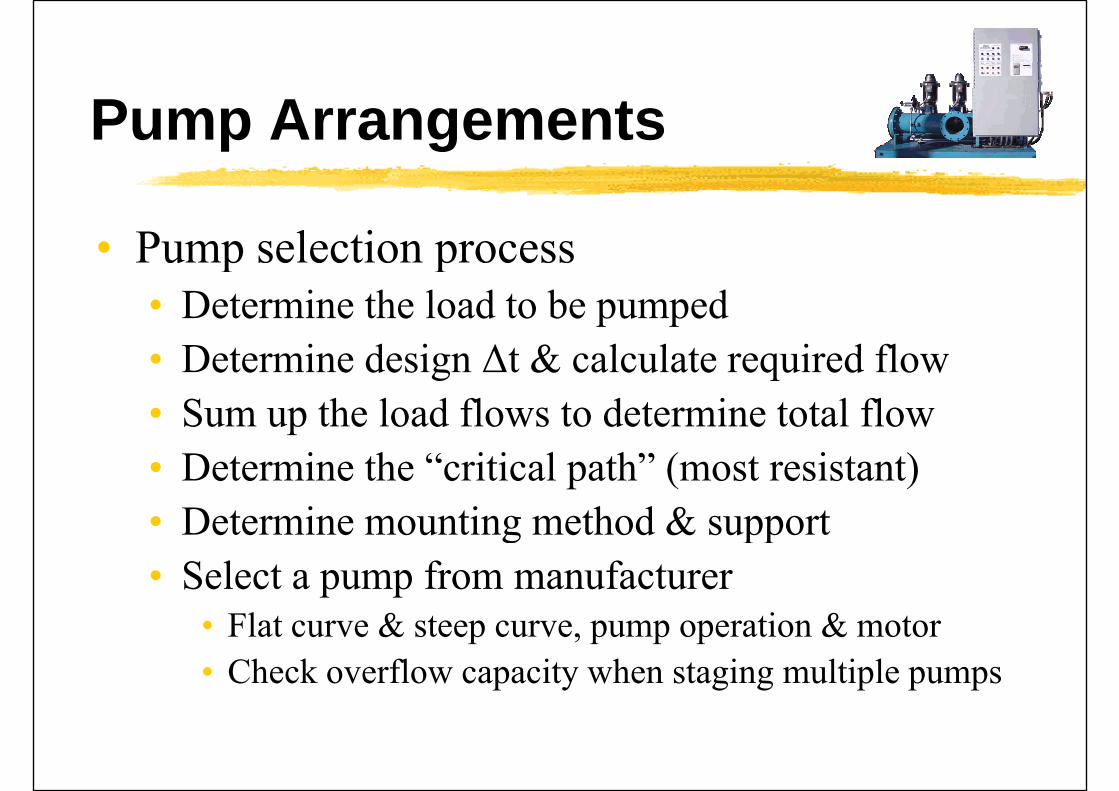
• Pump selection processp p• Determine the load to be pumped
D t i d i Δt & l l t i d fl• Determine design Δt & calculate required flow• Sum up the load flows to determine total flow• Determine the “critical path” (most resistant)• Determine mounting method & supportDetermine mounting method & support• Select a pump from manufacturer
Fl & i &• Flat curve & steep curve, pump operation & motor• Check overflow capacity when staging multiple pumps
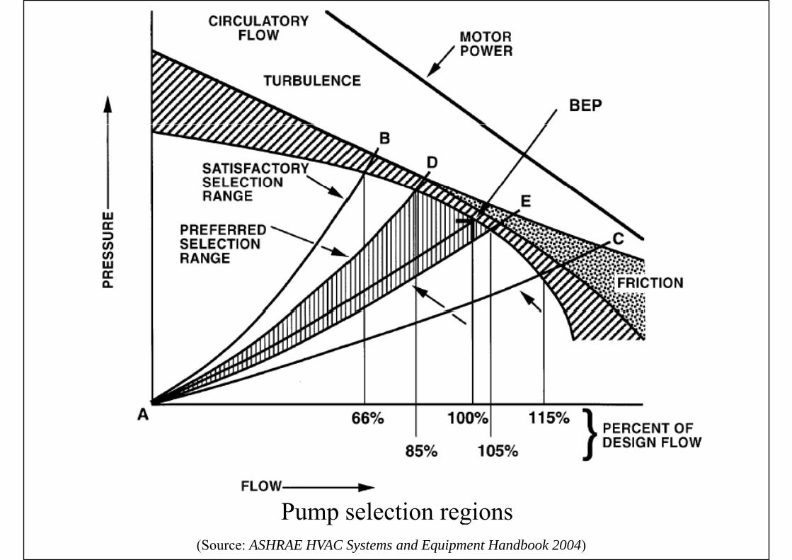
(Source: ASHRAE HVAC Systems and Equipment Handbook 2004)
Pump selection regions

(Source: Fundamentals of Water System Design)Pump performance data

Pump Arrangements
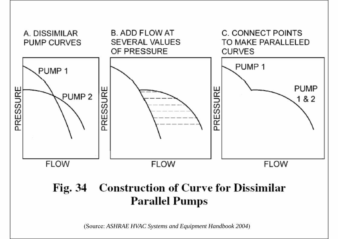
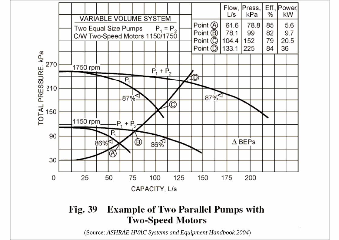
• Pumping arrangements & control scenariosPumping arrangements & control scenarios• Multiple pumps in parallel or series• Standby pump• Pumps with two-speed motorsPumps with two speed motors• Primary-secondary pumping• Variable-speed pumping• Distributed pumping• Distributed pumping
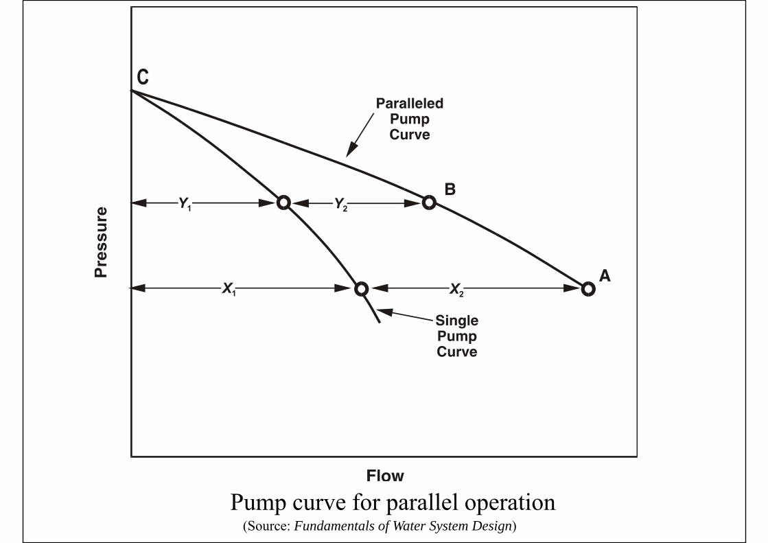
(Source: Fundamentals of Water System Design)Pump curve for parallel operation

(Source: Fundamentals of Water System Design)Operating conditions for parallel pump installation
(Source: ASHRAE HVAC Systems and Equipment Handbook 2004)

(Source: ASHRAE HVAC Systems and Equipment Handbook 2004)

(Source: Fundamentals of Water System Design)Pump curve for series operation

(Source: Fundamentals of Water System Design)Operating conditions for series pump
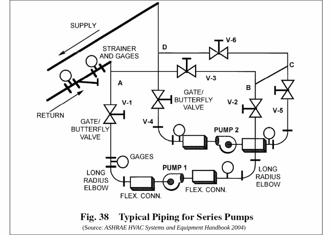
(Source: ASHRAE HVAC Systems and Equipment Handbook 2004)

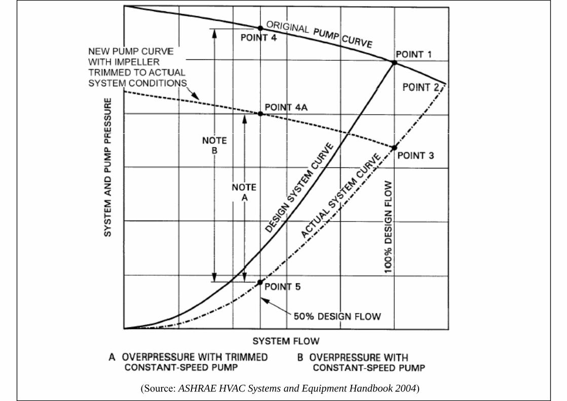
Matching Pumps to Systems
• Good piping system designGood piping system design• Match system characteristics to pump curve
• Trimming pump impellers• To reduce flow• To reduce flow• To match partload requirments
• Pump controlT d i &• Two-speed pumping & motors
• Variable speed pumpingp p p g
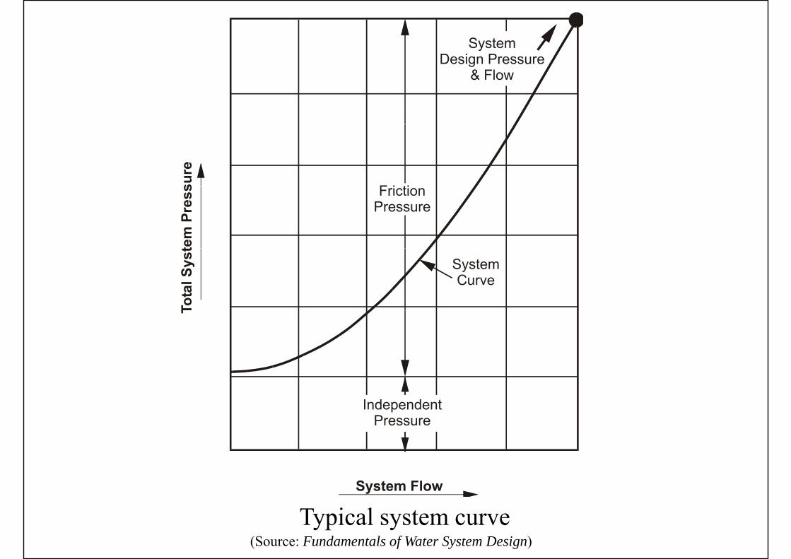
(Source: Fundamentals of Water System Design)Typical system curve
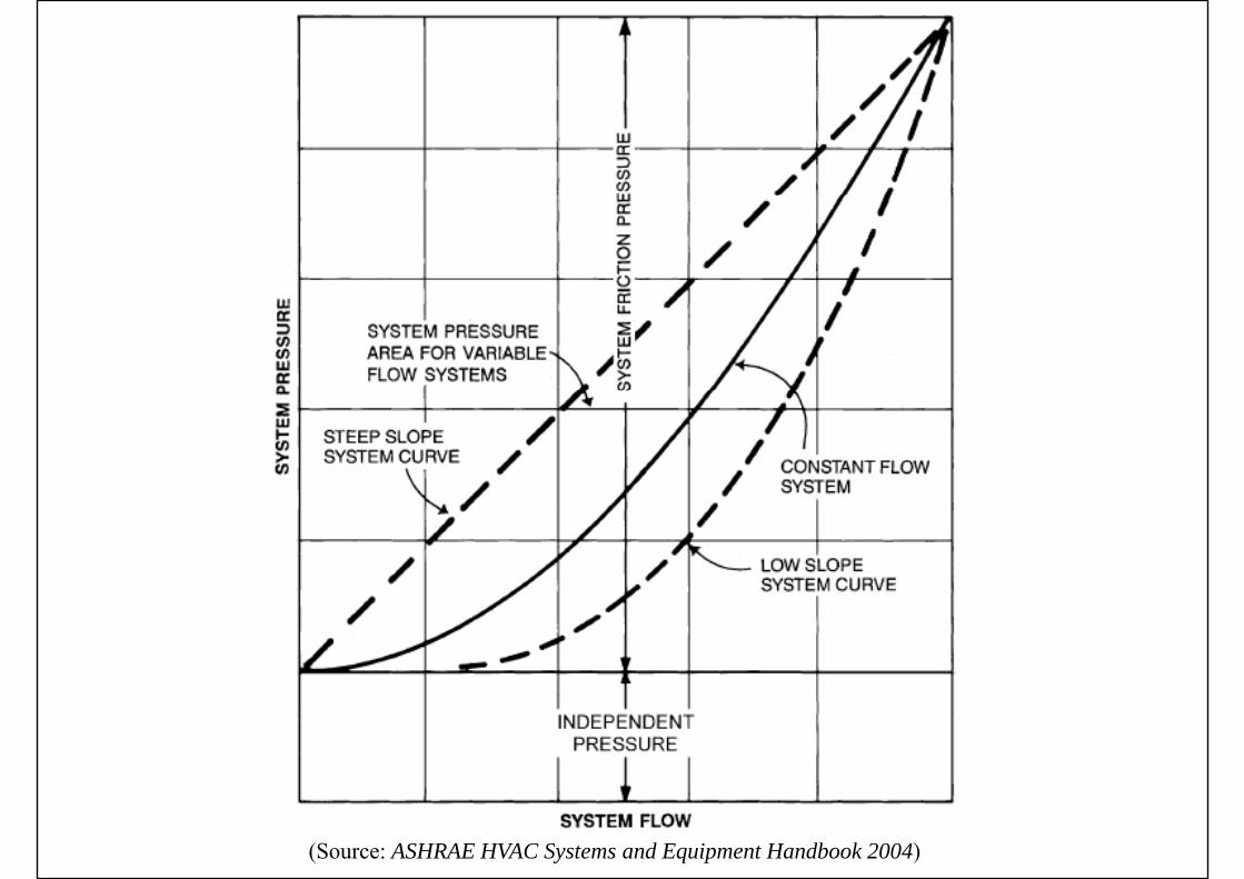
(Source: ASHRAE HVAC Systems and Equipment Handbook 2004)
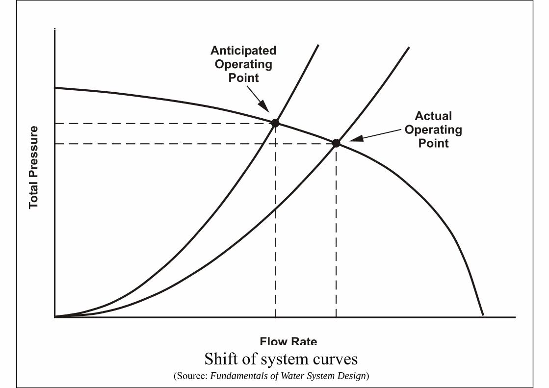
(Source: Fundamentals of Water System Design)Shift of system curves
(Source: ASHRAE HVAC Systems and Equipment Handbook 2004)
(Source: ASHRAE HVAC Systems and Equipment Handbook 2004)
Matching Pumps to Systems
• Modulation of pump-piping systemsModulation of pump piping systems• Throttle volume flow by using a valve
• Change flow resistance – new system curve• Also known as “riding on the curve”
• Turn water pumps on or off in sequence• Sudden increase/drop in flow rate and head• Sudden increase/drop in flow rate and head
• Vary the pump speed• System operating point move along the system curve• Requires the lowest pump power inputq p p p p
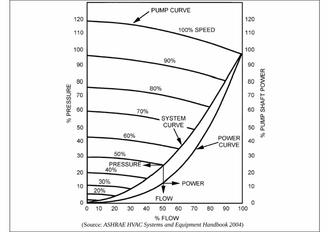
(Source: ASHRAE HVAC Systems and Equipment Handbook 2004)

Matching Pumps to Systems
• Plant loop (at constant flow) (production loop)p ( ) (p p)• To protect evaporator from freezing, a fairly
constant volume water flow is requiredconstant-volume water flow is required• Building loop (at variable flow)
• For saving energy at partload• A differential pressure transmitter is often installedA differential pressure transmitter is often installed
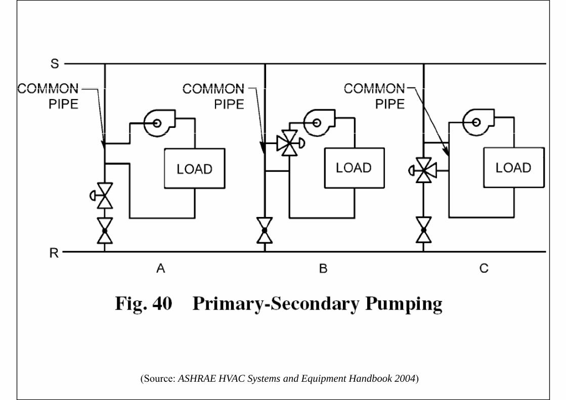
at the farthest end from the pumpP i d l• Primary-secondary loop• A short common pipe connects the 2 loops

Primary-secondary loop and pumping
(Source: ASHRAE HVAC Systems and Equipment Handbook 2004)
(Source: ASHRAE HVAC Systems and Equipment Handbook 2004)
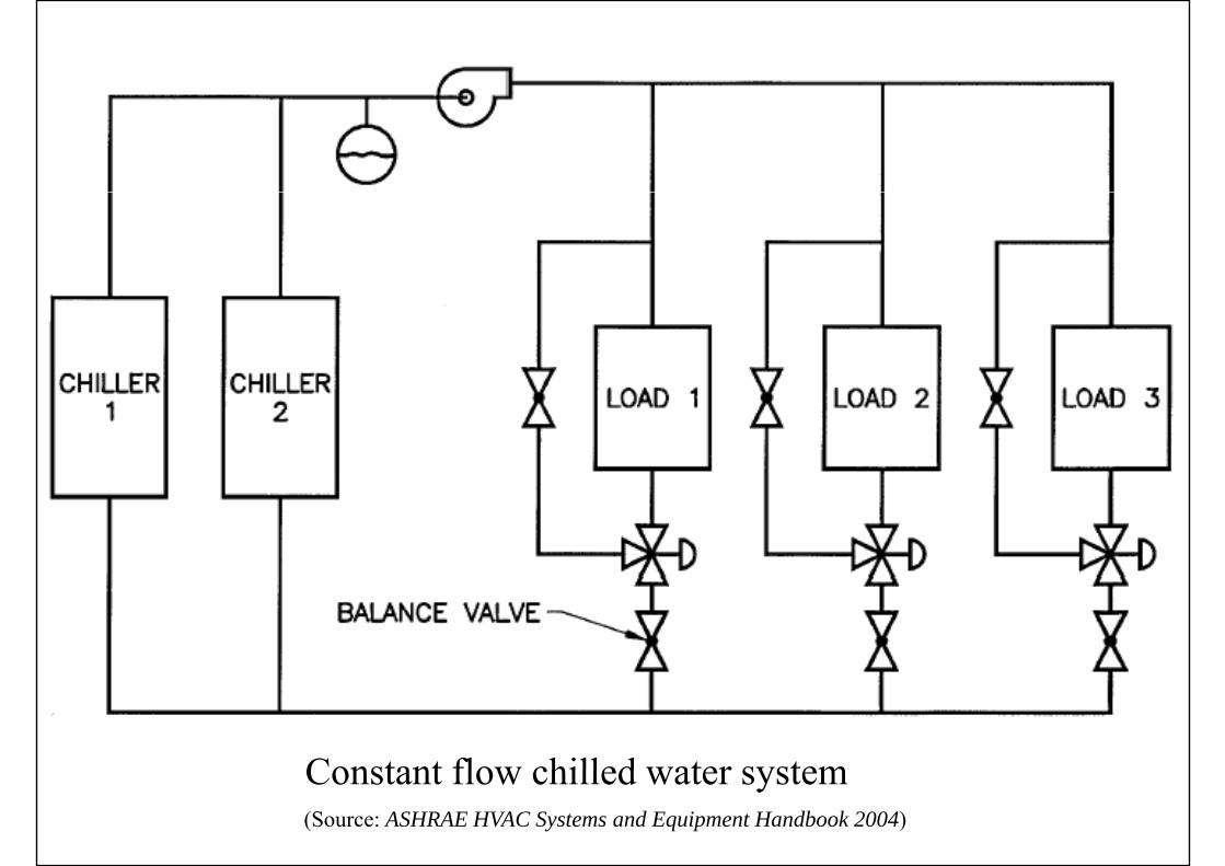
Constant flow chilled water system(Source: ASHRAE HVAC Systems and Equipment Handbook 2004)
Constant flow chilled water system

(Source: Wang, S. K., 2001. Handbook of Air Conditioning and Refrigeration)
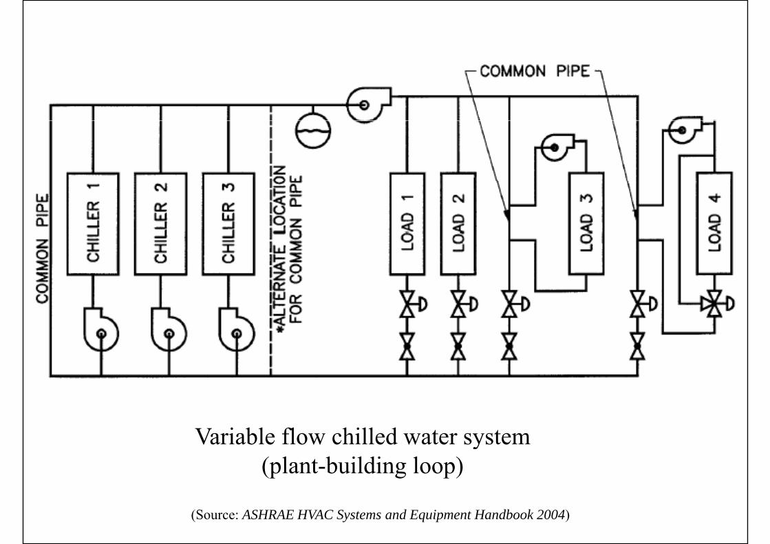
Variable flow chilled water system(plant-building loop)
(Source: ASHRAE HVAC Systems and Equipment Handbook 2004)
(Source: Wang, S. K., 2001. Handbook of Air Conditioning and Refrigeration)
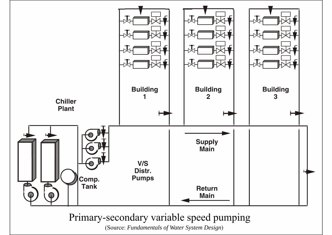
(Source: Fundamentals of Water System Design)Primary-secondary variable speed pumping
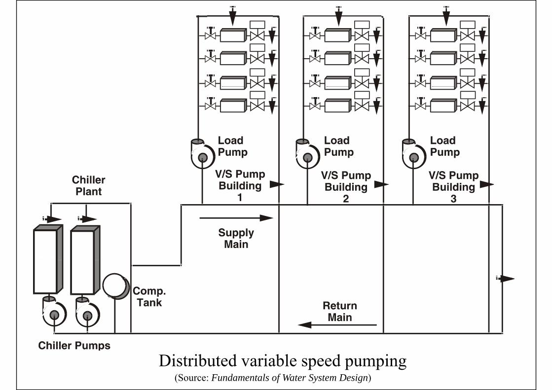
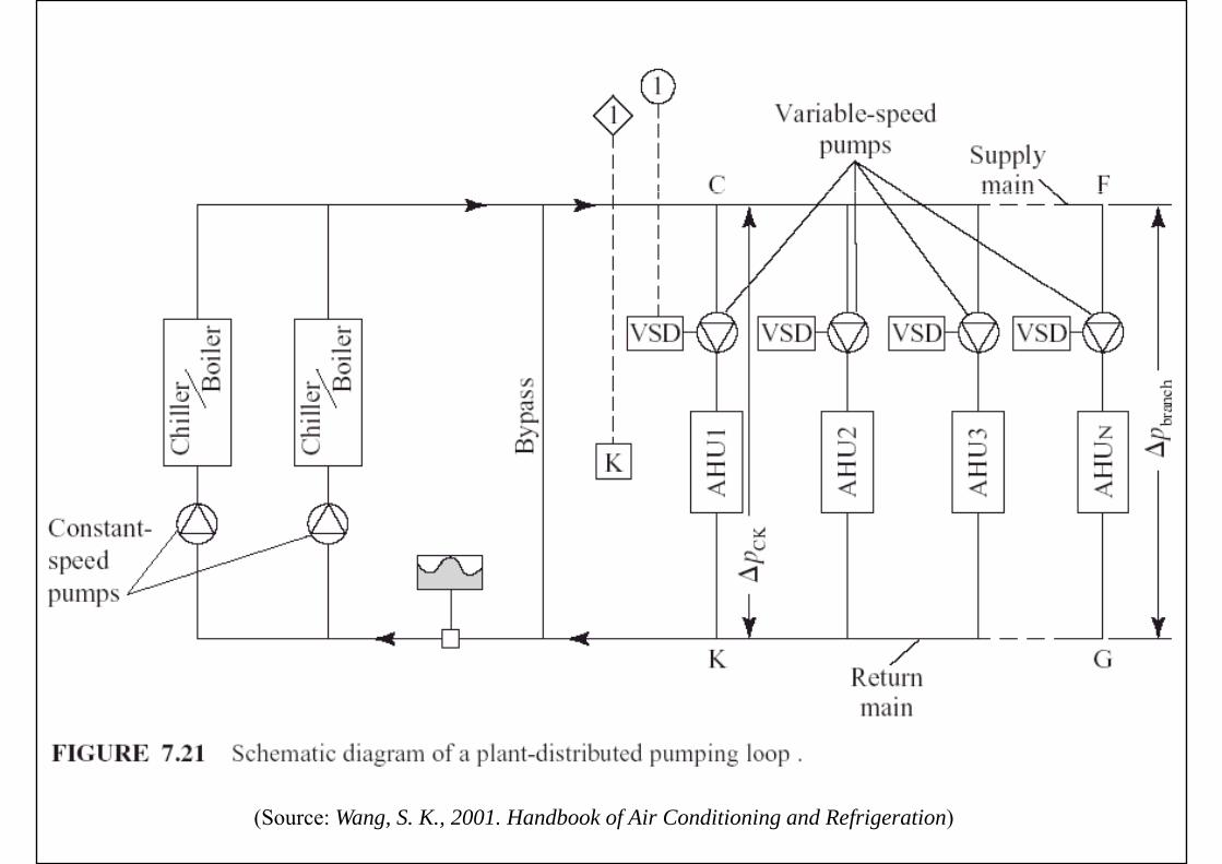
(Source: Fundamentals of Water System Design)Distributed variable speed pumping
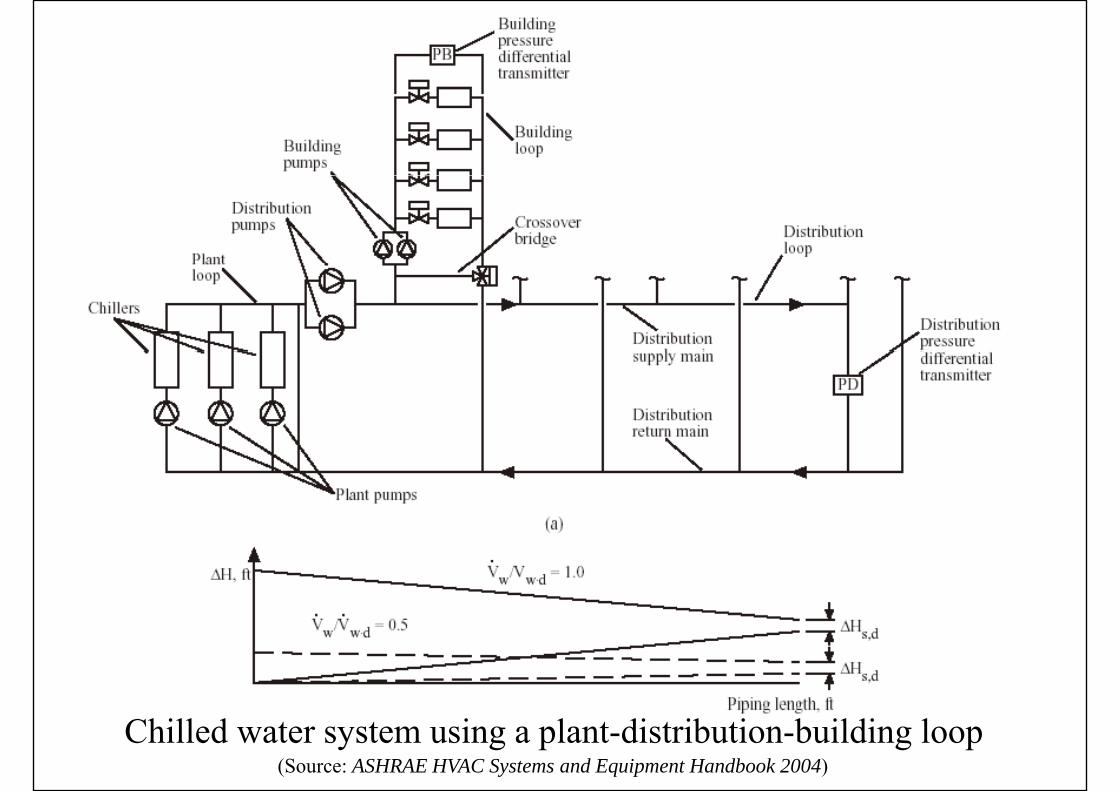
(Source: ASHRAE HVAC Systems and Equipment Handbook 2004)Chilled water system using a plant-distribution-building loop
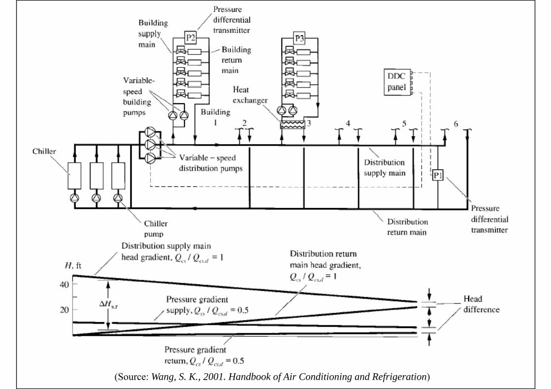
(Source: Wang, S. K., 2001. Handbook of Air Conditioning and Refrigeration)

Matching Pumps to Systems
• Chiller plant operation/performanceChiller plant operation/performance management• Parallel chiller arrangement• Series chiller arrangementSeries chiller arrangement• Decoupled chiller arrangement• Chiller plant control• Tertiary pumpingTertiary pumping