ch1introduction solid state physics
TRANSCRIPT
7/26/2019 ch1introduction solid state physics
http://slidepdf.com/reader/full/ch1introduction-solid-state-physics 1/34
1
Crystal Structures
1.1 Crystal Structure and Symmetry Groups
Although everyone has an intuitive idea of what a solid is, we will consider(in this book) only materials with a well-defined crystal structure. What wemean by a well-defined crystal structure is an arrangement of atoms in a lattice
such that the atomic arrangement looks absolutely identical when viewed fromtwo different points that are separated by a lattice translation vector . A fewdefinitions are useful.
Lattice
A lattice is an infinite array of points obtained from three primitive transla-tion vectors a1, a2, a3. Any point on the lattice is given by
n = n1a1 + n2a2 + n3a3. (1.1)
Translation Vector
Any pair of lattice points can be connected by a vector of the form
Tn1n2n3 = n1a1 + n2a2 + n3a3. (1.2)
The set of translation vectors form a group called the translation group of thelattice.
Group
A set of elements of any kind with a set of operations, by which any two
elements may be combined into a third, satisfying the following requirementsis called a group:
• The product (under group multiplication) of two elements of the groupbelongs to the group.
7/26/2019 ch1introduction solid state physics
http://slidepdf.com/reader/full/ch1introduction-solid-state-physics 2/34
4 1 Crystal Structures
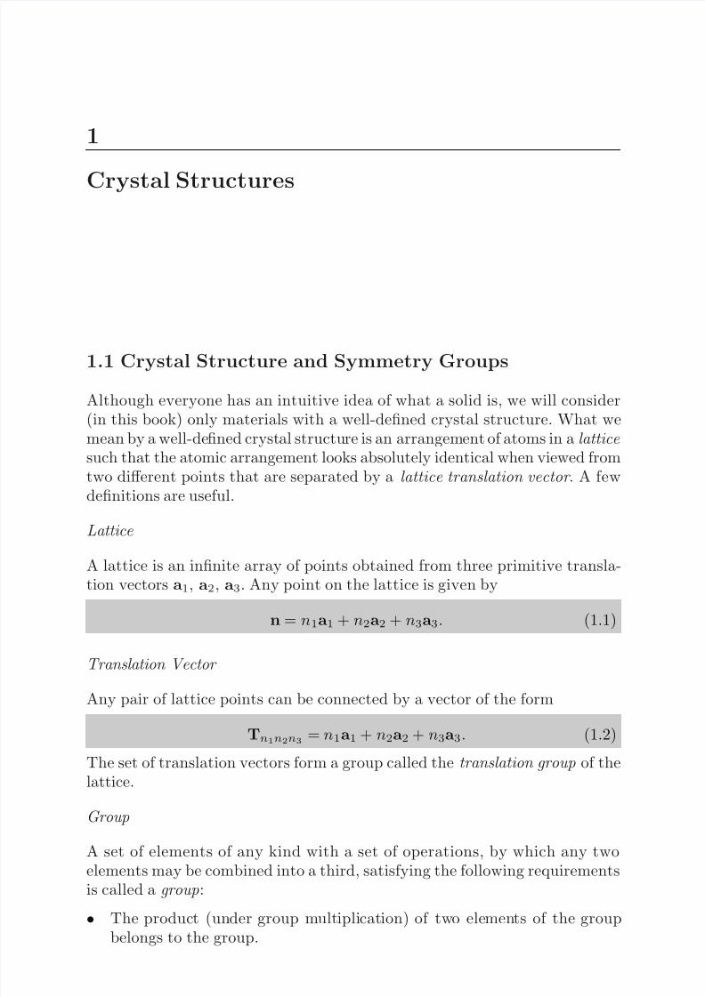
Fig. 1.1. Translation operations in a two-dimensional lattice
• The associative law holds for group multiplication.• The identity element belongs to the group.• Every element in the group has an inverse which belongs to the group.
Translation Group
The set of translations through any translation vector Tn1n2n3 forms a group.Group multiplication consists in simply performing the translation operations
consecutively. For example, as is shown in Fig. 1.1, we have T13 = T03 +T10. For the simple translation group the operations commute, i.e., TijTkl =TklTij for, every pair of translation vectors. This property makes the groupan Abelian group.
Point Group
There are other symmetry operations which leave the lattice unchanged. These
are rotations , reflections , and the inversion operations. These operations formthe point group of the lattice. As an example, consider the two-dimensionalsquare lattice (Fig. 1.2). The following operations (performed about any latticepoint) leave the lattice unchanged.
• E : identity• R1, R3: rotations by ±90◦
• R2: rotation by 180◦
• mx,my: reflections about x-axis and y-axis, respectively• m+,m−: reflections about the lines x = ±yThe multiplication table for this point group is given in Table 1.1. The oper-ations in the first column are the first (right) operations, such as m+ inR1m+ = my, and the operations listed in the first row are the second (left)operations, such as R1 in R1m+ = my.

7/26/2019 ch1introduction solid state physics
http://slidepdf.com/reader/full/ch1introduction-solid-state-physics 3/34
1.1 Crystal Structure and Symmetry Groups 5
Fig. 1.2. The two-dimensional square lattice
Table 1.1. Multiplication table for the group 4 mm. The first (right) operations,such as m+ in R1m+ = my, are listed in the first column, and the second (left)operations, such as R1 in R1m+ = my, are listed in the first row
Operation E R1 R2 R3 mx my m+ m−
E −1 = E E R1 R2 R3 mx my m+ m−
R−11 = R3 R3 E R1 R2 m+ m− my mx
R−12 = R2 R2 R3 E R1 my mx m− m+
R−13 = R1 R1 R2 R3 E m− m+ mx my
m−1x = mx mx m+ my m− E R2 R1 R3
m−1y = my my m− mx m+ R2 E R3 R1
m−1+ = m+ m+ my m− mx R3 R1 E R2
m−1−
= m− m− mx m+ my R1 R3 R2 E
12
3 4
Fig. 1.3. Identity operation on a two-dimensional square
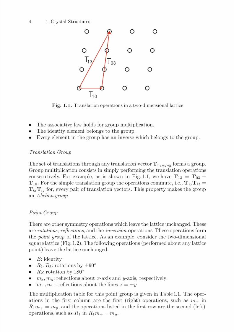
The multiplication table can be obtained as follows:
• Label the corners of the square (Fig. 1.3).• Operating with a symmetry operation simply reorders the labeling. For
example, see Fig. 1.4 f or symmetry operations of m+, R1, and mx.
Therefore, R1m+ = my. One can do exactly the same for all other prod-ucts, for example, such as myR1 = m+. It is also very useful to note what hap-pens to a point (x, y) under the operations of the point group (see Table 1.2).Note that under every group operation x → ±x or ±y and y → ±y or ±x.
7/26/2019 ch1introduction solid state physics
http://slidepdf.com/reader/full/ch1introduction-solid-state-physics 4/34
6 1 Crystal Structures
+
1
y
π
2
Fig. 1.4. Point symmetry operations on a two-dimensional square
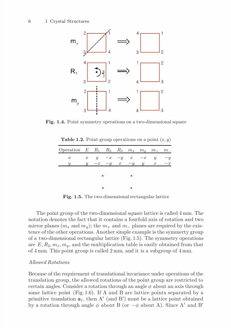
Table 1.2. Point group operations on a point (x, y)
Operation E R1 R2 R3 mx my m+ m−
x x y −x −y x −x y −yy y −x −y x −y y x −x
Fig. 1.5. The two-dimensional rectangular lattice
The point group of the two-dimensional square lattice is called 4 mm. Thenotation denotes the fact that it contains a fourfold axis of rotation and twomirror planes (mx and my); the m+ and m
− planes are required by the exis-
tence of the other operations. Another simple example is the symmerty groupof a two-dimensional rectangular lattice (Fig. 1.5). The symmetry operationsare E,R2,mx,my, and the multiplication table is easily obtained from thatof 4 mm. This point group is called 2 mm, and it is a subgroup of 4 mm.
Allowed Rotations
Because of the requirement of translational invariance under operations of thetranslation group, the allowed rotations of the point group are restricted to
certain angles. Consider a rotation through an angle φ about an axis throughsome lattice point (Fig. 1.6). If A and B are lattice points separated by aprimitive translation a1, then A (and B) must be a lattice point obtainedby a rotation through angle φ about B (or −φ about A). Since A and B
7/26/2019 ch1introduction solid state physics
http://slidepdf.com/reader/full/ch1introduction-solid-state-physics 5/34
1.1 Crystal Structure and Symmetry Groups 7
φ−φ
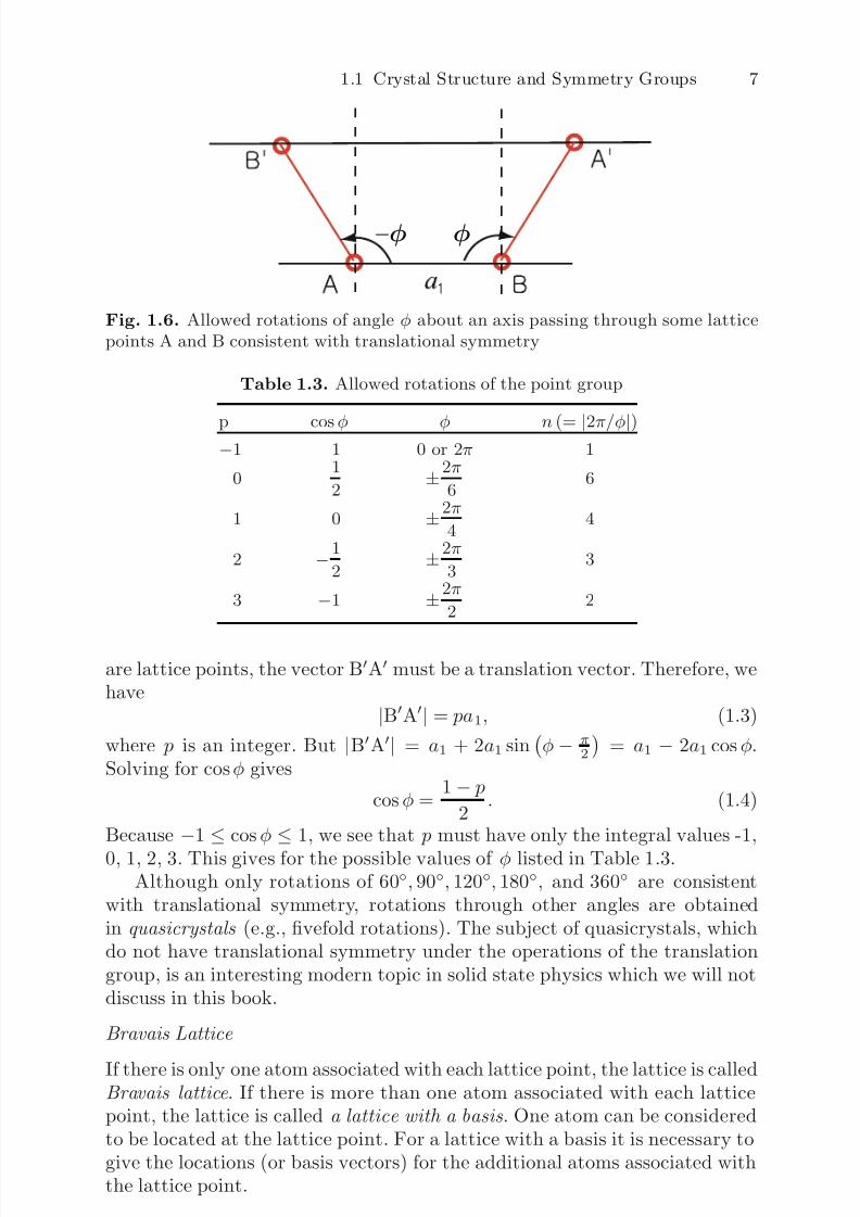
Fig. 1.6. Allowed rotations of angle φ about an axis passing through some latticepoints A and B consistent with translational symmetry
Table 1.3. Allowed rotations of the point group
p cos φ φ n (= |2π/φ|)−1 1 0 or 2π 1
0 1
2 ±
2π
6 6
1 0 ±2π
4 4
2 −1
2 ±
2π
3 3
3 −1 ±2π
2 2
are lattice points, the vector BA must be a translation vector. Therefore, wehave
|BA| = pa1, (1.3)
where p is an integer. But |BA| = a1 + 2a1 sinφ− π
2
= a1 − 2a1 cosφ.
Solving for cosφ gives
cosφ = 1 − p
2 . (1.4)
Because
−1
≤cosφ
≤1, we see that p must have only the integral values -1,
0, 1, 2, 3. This gives for the possible values of φ listed in Table 1.3.Although only rotations of 60◦, 90◦, 120◦, 180◦, and 360◦ are consistent
with translational symmetry, rotations through other angles are obtainedin quasicrystals (e.g., fivefold rotations). The subject of quasicrystals, whichdo not have translational symmetry under the operations of the translationgroup, is an interesting modern topic in solid state physics which we will notdiscuss in this book.
Bravais Lattice
If there is only one atom associated with each lattice point, the lattice is calledBravais lattice . If there is more than one atom associated with each latticepoint, the lattice is called a lattice with a basis . One atom can be consideredto be located at the lattice point. For a lattice with a basis it is necessary togive the locations (or basis vectors) for the additional atoms associated withthe lattice point.
7/26/2019 ch1introduction solid state physics
http://slidepdf.com/reader/full/ch1introduction-solid-state-physics 6/34
8 1 Crystal Structures
a
a
cos = a 2
a
b
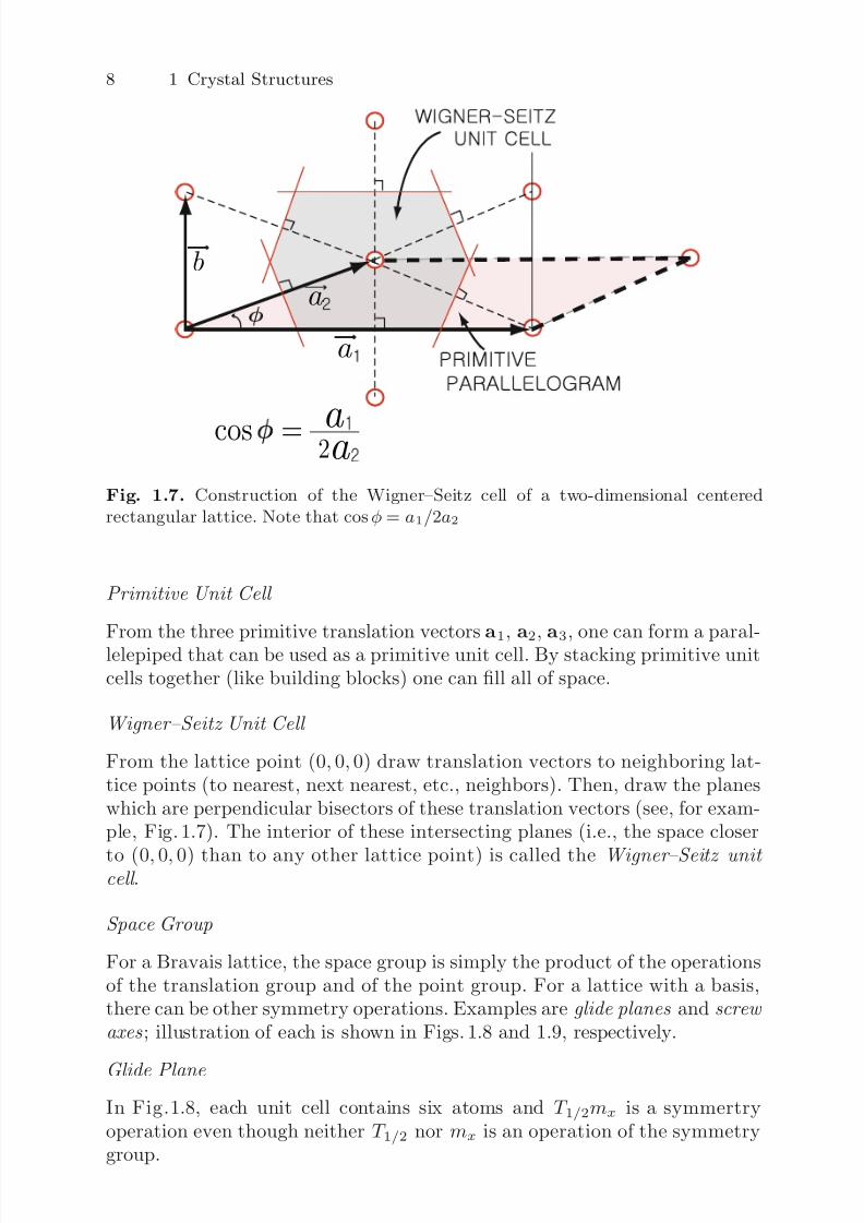
Fig. 1.7. Construction of the Wigner–Seitz cell of a two-dimensional centeredrectangular lattice. Note that cos φ = a1/2a2
Primitive Unit Cell
From the three primitive translation vectors a1, a2, a3, one can form a paral-lelepiped that can be used as a primitive unit cell. By stacking primitive unitcells together (like building blocks) one can fill all of space.
Wigner–Seitz Unit Cell
From the lattice point (0, 0, 0) draw translation vectors to neighboring lat-tice points (to nearest, next nearest, etc., neighbors). Then, draw the planeswhich are perpendicular bisectors of these translation vectors (see, for exam-ple, Fig. 1.7). The interior of these intersecting planes (i.e., the space closer
to (0, 0, 0) than to any other lattice point) is called the Wigner–Seitz unit cell .
Space Group
For a Bravais lattice, the space group is simply the product of the operationsof the translation group and of the point group. For a lattice with a basis,there can be other symmetry operations. Examples are glide planes and screw
axes ; illustration of each is shown in Figs. 1.8 and 1.9, respectively.
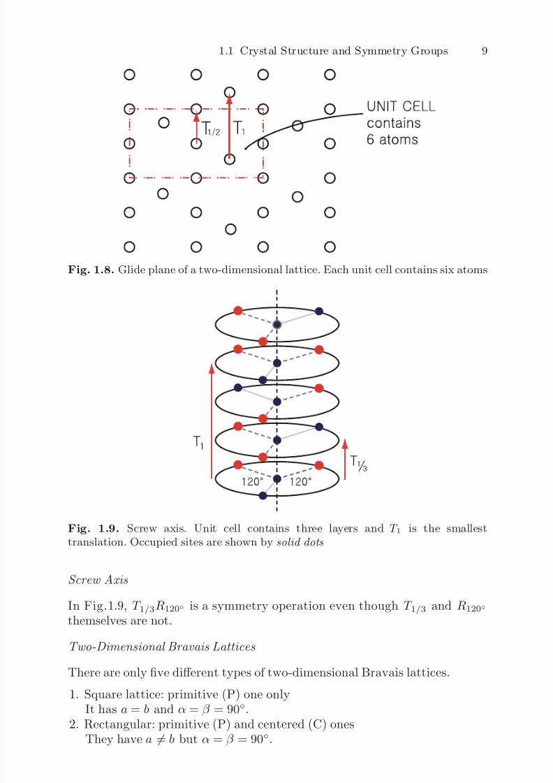
Glide Plane
In Fig.1.8, each unit cell contains six atoms and T 1/2mx is a symmertryoperation even though neither T 1/2 nor mx is an operation of the symmetrygroup.
7/26/2019 ch1introduction solid state physics
http://slidepdf.com/reader/full/ch1introduction-solid-state-physics 7/34
1.1 Crystal Structure and Symmetry Groups 9
Fig. 1.8. Glide plane of a two-dimensional lattice. Each unit cell contains six atoms
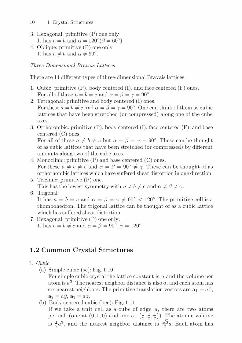
Fig. 1.9. Screw axis. Unit cell contains three layers and T 1 is the smallesttranslation. Occupied sites are shown by solid dots
Screw Axis
In Fig.1.9, T 1/3R120◦ is a symmetry operation even though T 1/3 and R120◦
themselves are not.
Two-Dimensional Bravais Lattices
There are only five different types of two-dimensional Bravais lattices.
1. Square lattice: primitive (P) one onlyIt has a = b and α = β = 90◦.
2. Rectangular: primitive (P) and centered (C) onesThey have a = b but α = β = 90◦.
7/26/2019 ch1introduction solid state physics
http://slidepdf.com/reader/full/ch1introduction-solid-state-physics 8/34
10 1 Crystal Structures
3. Hexagonal: primitive (P) one onlyIt has a = b and α = 120◦(β = 60◦).
4. Oblique: primitive (P) one onlyIt has a
= b and α
= 90◦.
Three-Dimensional Bravais Lattices
There are 14 different types of three-dimensional Bravais lattices.
1. Cubic: primitive (P), body centered (I), and face centered (F) ones.For all of these a = b = c and α = β = γ = 90◦.
2. Tetragonal: primitive and body centered (I) ones.For these a = b = c and α = β = γ = 90◦. One can think of them as cubiclattices that have been stretched (or compressed) along one of the cube
axes.3. Orthorombic: primitive (P), body centered (I), face centered (F), and base
centered (C) ones.For all of these a = b = c but α = β = γ = 90◦. These can be thoughtof as cubic lattices that have been stretched (or compressed) by differentamounts along two of the cube axes.
4. Monoclinic: primitive (P) and base centered (C) ones.For these a = b = c and α = β = 90◦ = γ . These can be thought of asorthorhombic lattices which have suffered shear distortion in one direction.
5. Triclinic: primitive (P) one.This has the lowest symmetry with a = b = c and α = β = γ .
6. Trigonal:It has a = b = c and α = β = γ = 90◦ < 120◦. The primitive cell is arhombohedron. The trigonal lattice can be thought of as a cubic latticewhich has suffered shear distortion.
7. Hexagonal: primitive (P) one only.It has a = b = c and α = β = 90◦, γ = 120◦.
1.2 Common Crystal Structures
1. Cubic
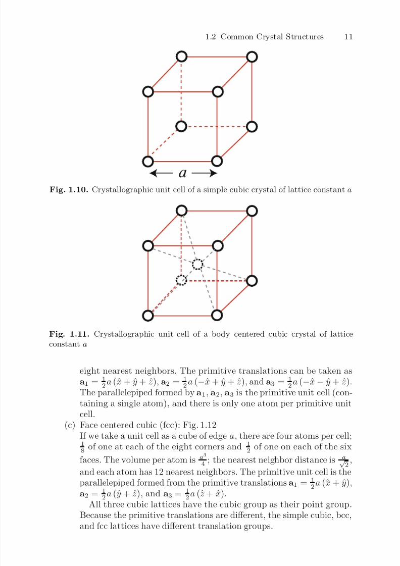
(a) Simple cubic (sc): Fig. 1.10For simple cubic crystal the lattice constant is a and the volume peratom is a3. The nearest neighbor distance is also a, and each atom hassix nearest neighbors. The primitive translation vectors are a1 = ax,a2 = ay, a3 = az.
(b) Body centered cubic (bcc): Fig. 1.11If we take a unit cell as a cube of edge a, there are two atomsper cell (one at (0, 0, 0) and one at
12, 1
2, 1
2
). The atomic volume
is 12a
3, and the nearest neighbor distance is√
32 a. Each atom has
7/26/2019 ch1introduction solid state physics
http://slidepdf.com/reader/full/ch1introduction-solid-state-physics 9/34
1.2 Common Crystal Structures 11
Fig. 1.10. Crystallographic unit cell of a simple cubic crystal of lattice constant a
Fig. 1.11. Crystallographic unit cell of a body centered cubic crystal of latticeconstant a
eight nearest neighbors. The primitive translations can be taken asa1 = 1
2a (x + y + z), a2 = 1
2a (−x + y + z), and a3 = 1
2a (−x− y + z).
The parallelepiped formed by a
1, a
2, a
3 is the primitive unit cell (con-taining a single atom), and there is only one atom per primitive unitcell.
(c) Face centered cubic (fcc): Fig. 1.12If we take a unit cell as a cube of edge a, there are four atoms per cell;18 of one at each of the eight corners and 1
2 of one on each of the six
faces. The volume per atom is a3
4 ; the nearest neighbor distance is a√ 2
,
and each atom has 12 nearest neighbors. The primitive unit cell is theparallelepiped formed from the primitive translations a1 = 1
2a (x + y),
a2 = 1
2a (y + z), and a3 = 1
2a (z + x).All three cubic lattices have the cubic group as their point group.Because the primitive translations are different, the simple cubic, bcc,and fcc lattices have different translation groups.
7/26/2019 ch1introduction solid state physics
http://slidepdf.com/reader/full/ch1introduction-solid-state-physics 10/34
12 1 Crystal Structures
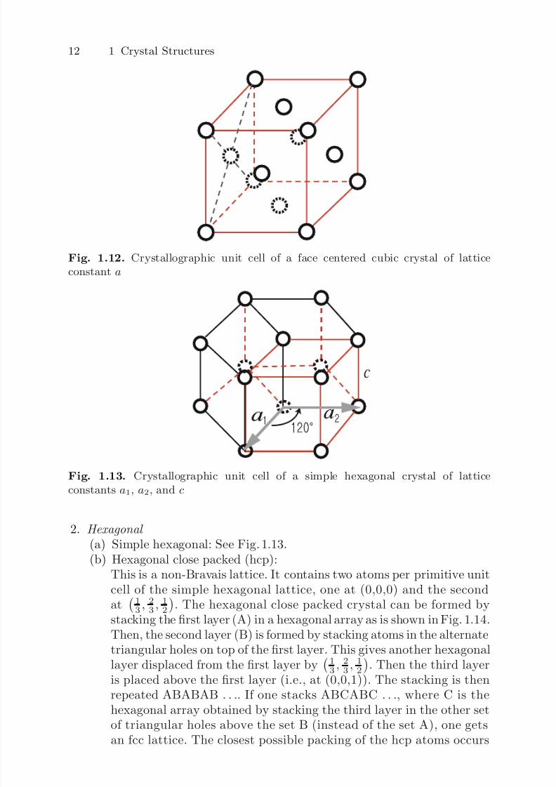
Fig. 1.12. Crystallographic unit cell of a face centered cubic crystal of lattice
constant a
Fig. 1.13. Crystallographic unit cell of a simple hexagonal crystal of latticeconstants a1, a2, and c
2. Hexagonal
(a) Simple hexagonal: See Fig. 1.13.(b) Hexagonal close packed (hcp):
This is a non-Bravais lattice. It contains two atoms per primitive unitcell of the simple hexagonal lattice, one at (0,0,0) and the secondat
13 ,
23 ,
12
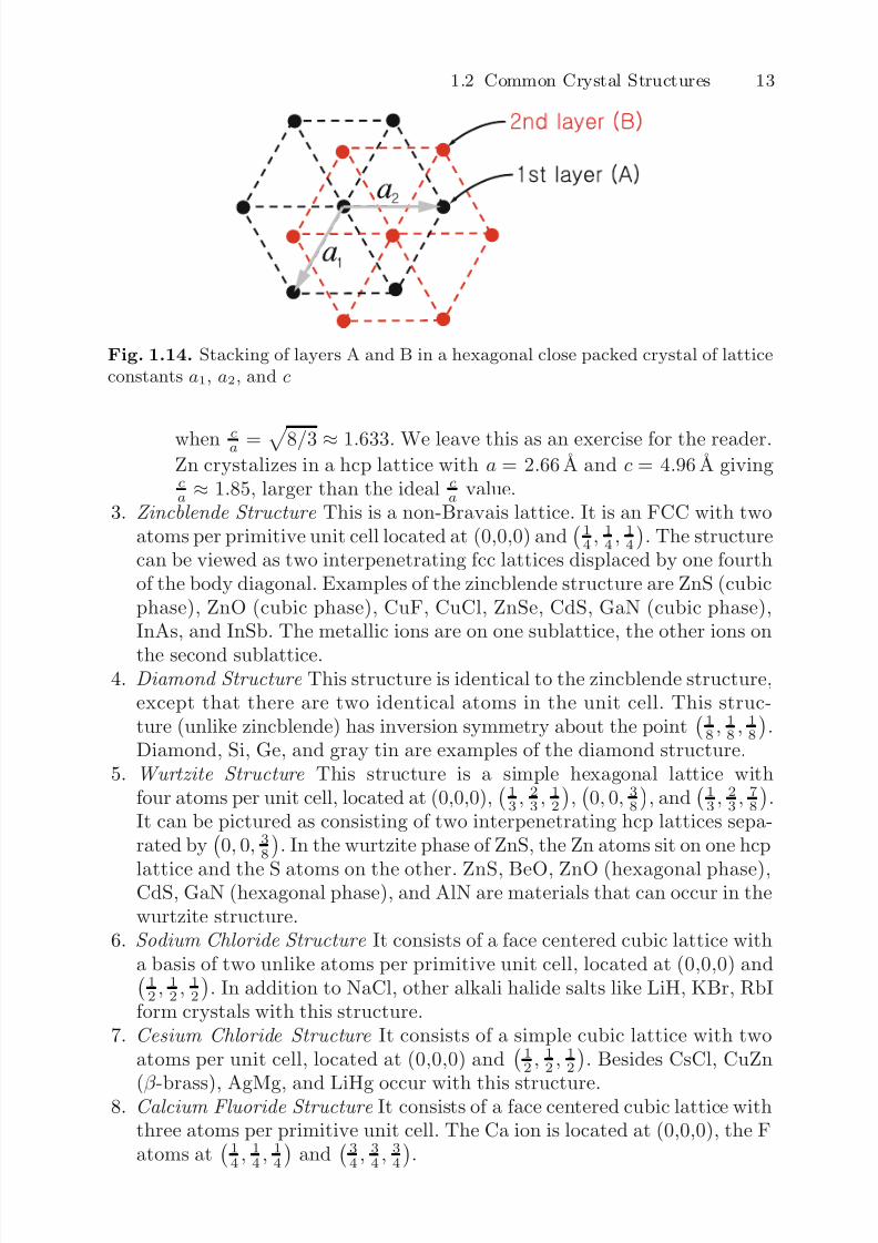
. The hexagonal close packed crystal can be formed by
stacking the first layer (A) in a hexagonal array as is shown in Fig. 1.14.Then, the second layer (B) is formed by stacking atoms in the alternatetriangular holes on top of the first layer. This gives another hexagonallayer displaced from the first layer by
13, 2
3, 1
2. Then the third layer
is placed above the first layer (i.e., at (0,0,1)). The stacking is then
repeated ABABAB . . .. If one stacks ABCABC . . ., where C is thehexagonal array obtained by stacking the third layer in the other setof triangular holes above the set B (instead of the set A), one getsan fcc lattice. The closest possible packing of the hcp atoms occurs
7/26/2019 ch1introduction solid state physics
http://slidepdf.com/reader/full/ch1introduction-solid-state-physics 11/34
1.2 Common Crystal Structures 13
Fig. 1.14. Stacking of layers A and B in a hexagonal close packed crystal of latticeconstants a1, a2, and c
when ca =
8/3 ≈ 1.633. We leave this as an exercise for the reader.Zn crystalizes in a hcp lattice with a = 2.66 A and c = 4.96 A givingca ≈ 1.85, larger than the ideal ca value.
3. Zincblende Structure This is a non-Bravais lattice. It is an FCC with twoatoms per primitive unit cell located at (0,0,0) and
14 ,
14 ,
14
. The structure
can be viewed as two interpenetrating fcc lattices displaced by one fourthof the body diagonal. Examples of the zincblende structure are ZnS (cubicphase), ZnO (cubic phase), CuF, CuCl, ZnSe, CdS, GaN (cubic phase),InAs, and InSb. The metallic ions are on one sublattice, the other ions on
the second sublattice.4. Diamond Structure This structure is identical to the zincblende structure,
except that there are two identical atoms in the unit cell. This struc-ture (unlike zincblende) has inversion symmetry about the point
18 ,
18 ,
18
.
Diamond, Si, Ge, and gray tin are examples of the diamond structure.5. Wurtzite Structure This structure is a simple hexagonal lattice with
four atoms per unit cell, located at (0,0,0),
13 ,
23 ,
12
,
0, 0, 38
, and
13 ,
23 ,
78
.
It can be pictured as consisting of two interpenetrating hcp lattices sepa-rated by 0, 0, 3
8. In the wurtzite phase of ZnS, the Zn atoms sit on one hcp
lattice and the S atoms on the other. ZnS, BeO, ZnO (hexagonal phase),CdS, GaN (hexagonal phase), and AlN are materials that can occur in thewurtzite structure.
6. Sodium Chloride Structure It consists of a face centered cubic lattice witha basis of two unlike atoms per primitive unit cell, located at (0,0,0) and
12 ,
12 ,
12
. In addition to NaCl, other alkali halide salts like LiH, KBr, RbI
form crystals with this structure.7. Cesium Chloride Structure It consists of a simple cubic lattice with two
atoms per unit cell, located at (0,0,0) and 12 ,
12 ,
12. Besides CsCl, CuZn
(β -brass), AgMg, and LiHg occur with this structure.8. Calcium Fluoride Structure It consists of a face centered cubic lattice withthree atoms per primitive unit cell. The Ca ion is located at (0,0,0), the Fatoms at
14 ,
14 ,
14
and
34 ,
34 ,
34
.
7/26/2019 ch1introduction solid state physics
http://slidepdf.com/reader/full/ch1introduction-solid-state-physics 12/34
14 1 Crystal Structures
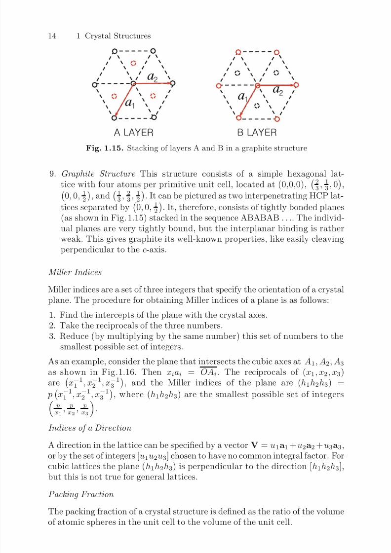
Fig. 1.15. Stacking of layers A and B in a graphite structure
9. Graphite Structure This structure consists of a simple hexagonal lat-tice with four atoms per primitive unit cell, located at (0,0,0), 2
3 , 13 , 0,
0, 0, 12
, and
13 , 23 , 12
. It can be pictured as two interpenetrating HCP lat-tices separated by
0, 0, 1
2
. It, therefore, consists of tightly bonded planes
(as shown in Fig. 1.15) stacked in the sequence ABABAB . . .. The individ-ual planes are very tightly bound, but the interplanar binding is ratherweak. This gives graphite its well-known properties, like easily cleavingperpendicular to the c-axis.
Miller Indices
Miller indices are a set of three integers that specify the orientation of a crystalplane. The procedure for obtaining Miller indices of a plane is as follows:
1. Find the intercepts of the plane with the crystal axes.2. Take the reciprocals of the three numbers.3. Reduce (by multiplying by the same number) this set of numbers to the
smallest possible set of integers.
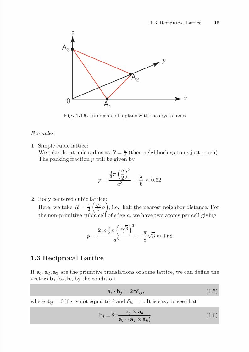
As an example, consider the plane that intersects the cubic axes at A1, A2, A3
as shown in Fig.1.16. Then xiai = OAi. The reciprocals of (x1, x2, x3)are x−1
1 , x−1
2 , x−1
3, and the Miller indices of the plane are (h
1h
2h
3) =
px−1
1 , x−12 , x
−13
, where (h1h2h3) are the smallest possible set of integers
px1, px2 ,
px3
.
Indices of a Direction
A direction in the lattice can be specified by a vector V = u1a1 +u2a2 +u3a3,or by the set of integers [u1u2u3] chosen to have no common integral factor. Forcubic lattices the plane (h1h2h3) is perpendicular to the direction [h1h2h3],but this is not true for general lattices.
Packing Fraction
The packing fraction of a crystal structure is defined as the ratio of the volumeof atomic spheres in the unit cell to the volume of the unit cell.
7/26/2019 ch1introduction solid state physics
http://slidepdf.com/reader/full/ch1introduction-solid-state-physics 13/34
1.3 Reciprocal Lattice 15
Fig. 1.16. Intercepts of a plane with the crystal axes
Examples
1. Simple cubic lattice:We take the atomic radius as R = a
2 (then neighboring atoms just touch).The packing fraction p will be given by
p =
43π
a
23
a3
= π
6 ≈0.52
2. Body centered cubic lattice:
Here, we take R = 12
√ 3
2 a
, i.e., half the nearest neighbor distance. For
the non-primitive cubic cell of edge a, we have two atoms per cell giving
p =2 × 4
3πa√
34
3
a3 =
π
8
√ 3 ≈ 0.68
1.3 Reciprocal Lattice
If a1,a2,a3 are the primitive translations of some lattice, we can define thevectors b1,b2,b3 by the condition
ai · bj = 2πδ ij, (1.5)
where δ ij = 0 if i is not equal to j and δ ii = 1. It is easy to see that
bi = 2π aj × ak
ai · (aj × ak), (1.6)
7/26/2019 ch1introduction solid state physics
http://slidepdf.com/reader/full/ch1introduction-solid-state-physics 14/34
16 1 Crystal Structures
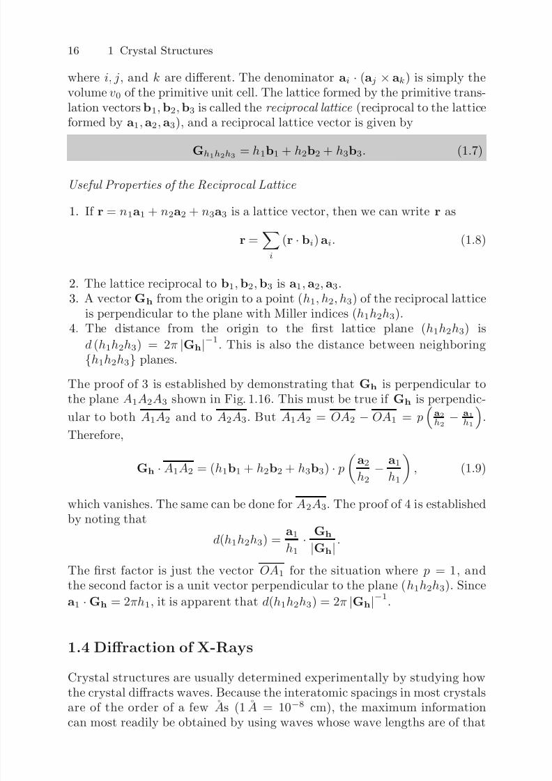
where i, j, and k are different. The denominator ai · (aj × ak) is simply thevolume v0 of the primitive unit cell. The lattice formed by the primitive trans-lation vectors b1,b2,b3 is called the reciprocal lattice (reciprocal to the latticeformed by a1,a2,a3), and a reciprocal lattice vector is given by
Gh1h2h3 = h1b1 + h2b2 + h3b3. (1.7)
Useful Properties of the Reciprocal Lattice
1. If r = n1a1 + n2a2 + n3a3 is a lattice vector, then we can write r as
r =i
(r · bi) ai. (1.8)
2. The lattice reciprocal to b1,b2,b3 is a1, a2, a3.3. A vector Gh from the origin to a point (h1, h2, h3) of the reciprocal lattice
is perpendicular to the plane with Miller indices (h1h2h3).4. The distance from the origin to the first lattice plane (h1h2h3) is
d (h1h2h3) = 2π |Gh|−1. This is also the distance between neighboring
{h1h2h3} planes.
The proof of 3 is established by demonstrating that Gh is perpendicular tothe plane A1A2A3 shown in Fig. 1.16. This must be true if Gh is perpendic-
ular to both A1A2 and to A2A3. But A1A2 = OA2 − OA1 = pa2h2
− a1h1
.
Therefore,
Gh · A1A2 = (h1b1 + h2b2 + h3b3) · p
a2
h2− a1
h1
, (1.9)
which vanishes. The same can be done for A2A3. The proof of 4 is establishedby noting that
d(h1h2h3) = a1
h1 · Gh
|Gh|.
The first factor is just the vector OA1 for the situation where p = 1, andthe second factor is a unit vector perpendicular to the plane (h1h2h3). Since
a1 · Gh = 2πh1, it is apparent that d(h1h2h3) = 2π |Gh|−1.
1.4 Diffraction of X-Rays
Crystal structures are usually determined experimentally by studying howthe crystal diffracts waves. Because the interatomic spacings in most crystalsare of the order of a few As (1 A = 10−8 cm), the maximum informationcan most readily be obtained by using waves whose wave lengths are of that

7/26/2019 ch1introduction solid state physics
http://slidepdf.com/reader/full/ch1introduction-solid-state-physics 15/34
1.4 Diffraction of X-Rays 17
order of magnitude. Electromagnetic, electron, or neutron waves can be usedto study diffraction by a crystal. For electromagnetic waves, E = hν , whereE is the energy of the photon, ν = c
λ is its frequency and λ its wave length,and h is Planck’s constant. For λ = 10−8 cm, c = 3
×1010 cm/s and h =
6.6 × 10⁻²⁷ erg · s, the photon energy is equal to roughly 2 × 10⁻⁸ ergs or1.24 × 104 eV. Photons of energies of tens of kilovolts are in the X-ray range.For electron waves, p = h
λ 6.6 × 10⁻¹⁹ g · cm/s when λ = 10−8 cm. This
gives E = p2
2me, where me 0.9 × 10⁻²⁷g, of 2.4 × 10⁻¹⁰ ergs or roughly
150 eV. For neutron waves, we need simply replace me by mn = 1.67×10⁻²⁴ gto obtain E = 1.3 × 10⁻¹³ ergs 0.08 eV. Thus neutron energies are of theorder of a tenth of an eV. Neutron scattering has the advantages that the lowenergy makes inelastic scattering studies more accurate and that the magneticmoment of the neutron allows the researcher to obtain information about
the magnetic structure. It has the disadvantage that high intensity neutronsources are not as easily obtained as X-ray sources.
1.4.1 Bragg Reflection
We have already seen that we can discuss crystal planes in a lattice structure.Assume that an incident X-ray is specularly reflected by a set of crystal planesas shown in Fig. 1.17. Constructive interference occurs when the difference inpath length is an integral number of wave length λ. It is clear that this occurs
when
2d sin θ = nλ, (1.10)
where d is the interplane spacing, θ is the angle between the incident beamand the crystal planes, as is shown on the figure, and n is an integer. Equation(1.10) is known as Bragg’s law .
1.4.2 Laue Equations
A slightly more elegant discussion of diffraction from a crystal can be obtainedas follows:
θ
θ
INCIDENT
WAVE
REFLECTED
WAVE
Fig. 1.17. Specular reflection of X-rays by a set of crystal planes separated by adistance d
7/26/2019 ch1introduction solid state physics
http://slidepdf.com/reader/full/ch1introduction-solid-state-physics 16/34
18 1 Crystal Structures
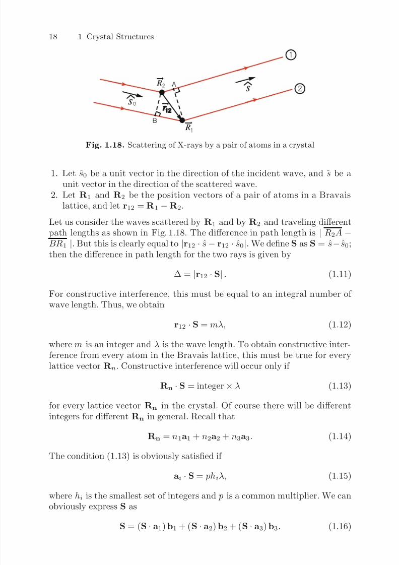
Fig. 1.18. Scattering of X-rays by a pair of atoms in a crystal
1. Let s0 be a unit vector in the direction of the incident wave, and s be aunit vector in the direction of the scattered wave.
2. Let R1 and R2 be the position vectors of a pair of atoms in a Bravaislattice, and let r12 = R1 − R2.
Let us consider the waves scattered by R1 and by R2 and traveling differentpath lengths as shown in Fig. 1.18. The difference in path length is | R2A −BR1 |. But this is clearly equal to |r12 · s− r12 · s0|. We define S as S = s− s0;then the difference in path length for the two rays is given by
∆ = |r12 · S| . (1.11)
For constructive interference, this must be equal to an integral number of wave length. Thus, we obtain
r12 · S = mλ, (1.12)
where m is an integer and λ is the wave length. To obtain constructive inter-ference from every atom in the Bravais lattice, this must be true for everylattice vector Rn. Constructive interference will occur only if
Rn
·S = integer
×λ (1.13)
for every lattice vector Rn in the crystal. Of course there will be differentintegers for different Rn in general. Recall that
Rn = n1a1 + n2a2 + n3a3. (1.14)
The condition (1.13) is obviously satisfied if
ai · S = phiλ, (1.15)
where hi is the smallest set of integers and p is a common multiplier. We canobviously express S as
S = (S · a1) b1 + (S · a2) b2 + (S · a3) b3. (1.16)
7/26/2019 ch1introduction solid state physics
http://slidepdf.com/reader/full/ch1introduction-solid-state-physics 17/34
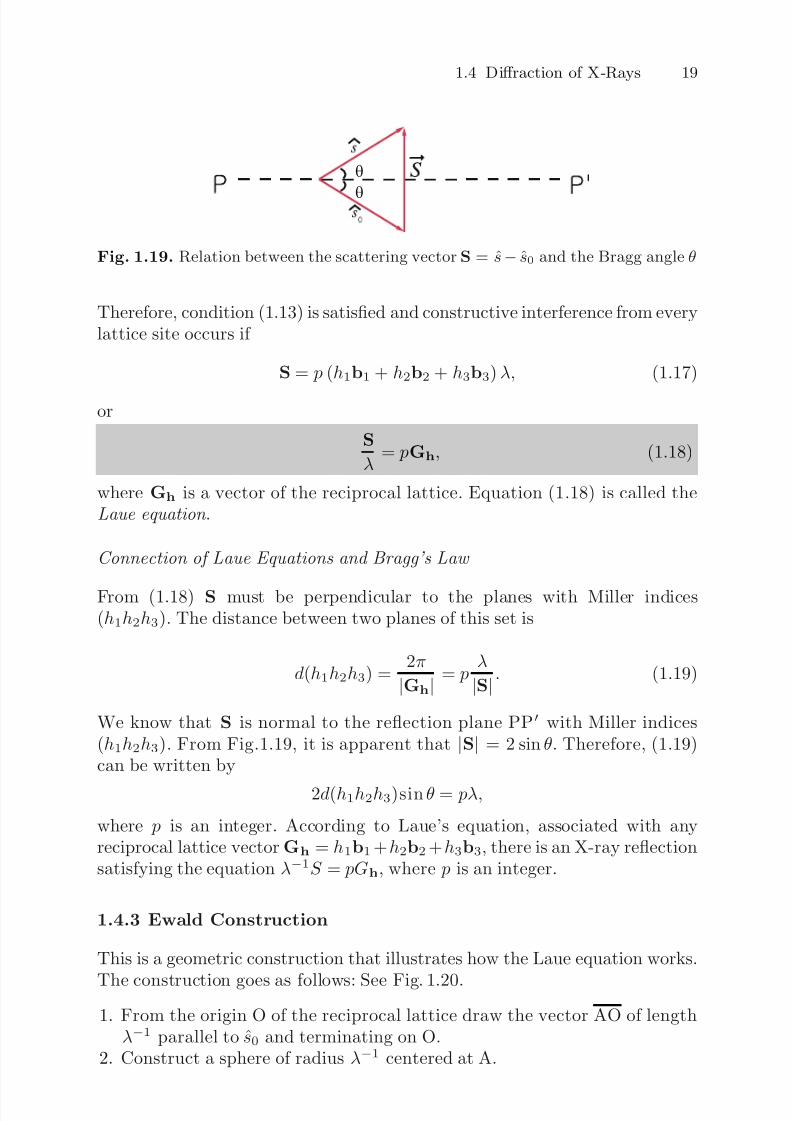
1.4 Diffraction of X-Rays 19
θ
θ
Fig. 1.19. Relation between the scattering vector S = s− s0 and the Bragg angle θ
Therefore, condition (1.13) is satisfied and constructive interference from everylattice site occurs if
S = p (h1b1 + h2b2 + h3b3)λ, (1.17)
or
S
λ = pGh, (1.18)
where Gh is a vector of the reciprocal lattice. Equation (1.18) is called theLaue equation .
Connection of Laue Equations and Bragg’s Law
From (1.18) S must be perpendicular to the planes with Miller indices(h1h2h3). The distance between two planes of this set is
d(h1h2h3) = 2π
|Gh| = p λ
|S| . (1.19)
We know that S is normal to the reflection plane PP with Miller indices(h1h2h3). From Fig.1.19, it is apparent that |S| = 2 sin θ. Therefore, (1.19)can be written by
2d(h1h2h3)sin θ = pλ,
where p is an integer. According to Laue’s equation, associated with anyreciprocal lattice vector Gh = h1b1 +h2b2 +h3b3, there is an X-ray reflectionsatisfying the equation λ−1S = pGh, where p is an integer.
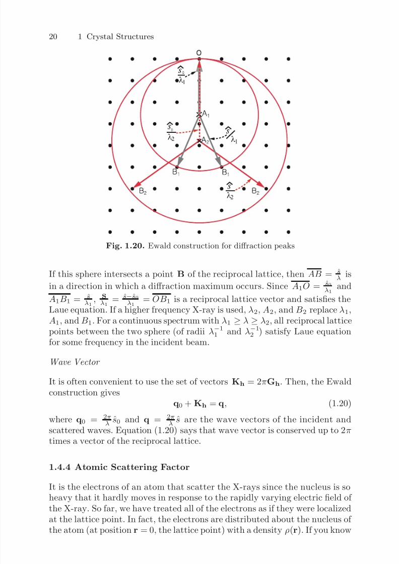
1.4.3 Ewald Construction
This is a geometric construction that illustrates how the Laue equation works.
The construction goes as follows: See Fig. 1.20.
1. From the origin O of the reciprocal lattice draw the vector AO of lengthλ−1 parallel to s0 and terminating on O.
2. Construct a sphere of radius λ−1 centered at A.
7/26/2019 ch1introduction solid state physics
http://slidepdf.com/reader/full/ch1introduction-solid-state-physics 18/34
20 1 Crystal Structures
λ2 λ1
λ1
λ2
Fig. 1.20. Ewald construction for diffraction peaks
If this sphere intersects a point B of the reciprocal lattice, then AB = sλ is
in a direction in which a diffraction maximum occurs. Since A1O = s0λ1
and
A1B1 = sλ1 , Sλ1 = s−s0
λ1 = OB1 is a reciprocal lattice vector and satisfies theLaue equation. If a higher frequency X-ray is used, λ2, A2, and B2 replace λ1,A1, and B1. For a continuous spectrum with λ1 ≥ λ ≥ λ2, all reciprocal latticepoints between the two sphere (of radii λ−1
1 and λ−12 ) satisfy Laue equation
for some frequency in the incident beam.
Wave Vector
It is often convenient to use the set of vectors Kh = 2πGh. Then, the Ewald
construction gives q0 + Kh = q, (1.20)
where q0 = 2πλ s0 and q = 2π
λ s are the wave vectors of the incident andscattered waves. Equation (1.20) says that wave vector is conserved up to 2πtimes a vector of the reciprocal lattice.
1.4.4 Atomic Scattering Factor
It is the electrons of an atom that scatter the X-rays since the nucleus is so
heavy that it hardly moves in response to the rapidly varying electric field of the X-ray. So far, we have treated all of the electrons as if they were localizedat the lattice point. In fact, the electrons are distributed about the nucleus of the atom (at position r = 0, the lattice point) with a density ρ(r). If you know
7/26/2019 ch1introduction solid state physics
http://slidepdf.com/reader/full/ch1introduction-solid-state-physics 19/34
1.4 Diffraction of X-Rays 21
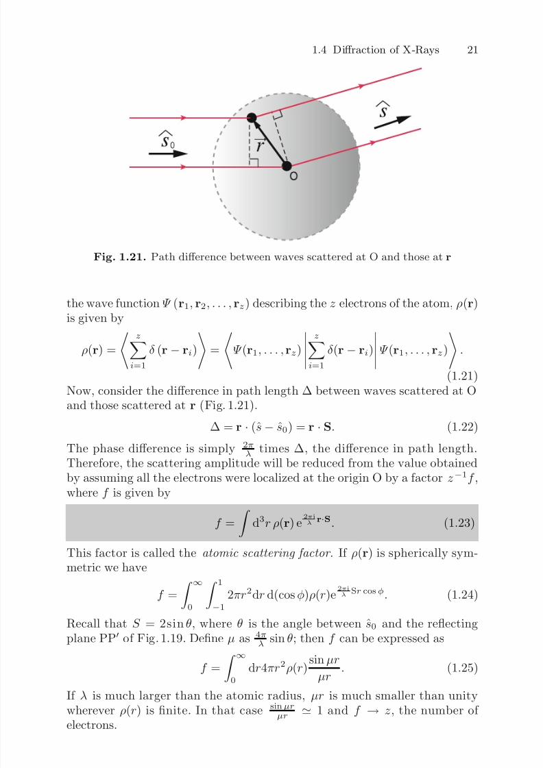
Fig. 1.21. Path difference between waves scattered at O and those at r
the wave function Ψ (r1, r2, . . . , rz) describing the z electrons of the atom, ρ(r)is given by
ρ(r) =
zi=1
δ (r − ri)
=
Ψ (r1, . . . , rz)
z
i=1
δ (r − ri)
Ψ (r1, . . . , rz)
.
(1.21)Now, consider the difference in path length ∆ between waves scattered at O
and those scattered at r (Fig. 1.21).
∆ = r · (s− s0) = r · S. (1.22)
The phase difference is simply 2πλ times ∆, the difference in path length.
Therefore, the scattering amplitude will be reduced from the value obtainedby assuming all the electrons were localized at the origin O by a factor z−1f ,where f is given by
f = d3r ρ(r) e2πiλ r·S. (1.23)
This factor is called the atomic scattering factor . If ρ(r) is spherically sym-metric we have
f =
∞0
1
−1
2πr2dr d(cosφ)ρ(r)e2πiλ
Sr cosφ. (1.24)
Recall that S = 2sin θ, where θ is the angle between s0 and the reflectingplane PP of Fig. 1.19. Define µ as 4π
λ sin θ; then f can be expressed as
f = ∞
0 dr4πr
2
ρ(r)
sinµr
µr . (1.25)
If λ is much larger than the atomic radius, µr is much smaller than unitywherever ρ(r) is finite. In that case sinµr
µr 1 and f → z, the number of electrons.
7/26/2019 ch1introduction solid state physics
http://slidepdf.com/reader/full/ch1introduction-solid-state-physics 20/34
22 1 Crystal Structures
1.4.5 Geometric Structure Factor
So far we have considered only a Bravais lattice. For a non-Bravais lattice thescattered amplitude depends on the locations and atomic scattering factors
of all the atoms in the unit cell. Suppose a crystal structure contains atomsat positions rj with atomic scattering factors f j . It is not difficult to see thatthis changes the scattered amplitude by a factor
F (h1, h2, h3) =j
f je2πiλ rj ·S(h1h2h3) (1.26)
for the scattering from a plane with Miller indices (h1h2h3). In (1.26) theposition vector rj of the jth atom can be expressed in terms of the primitivetranslation vectors ai
rj =
i µji
ai. (1.27)
For example, in a hcp lattice r1 = (0, 0, 0) and r2 = ( 13 ,
23 ,
12 ) when expressed
in terms of the primitive translation vectors. Of course, S(h1h2h3) equal toλ
i hibi, where bi are primitive translation vectors in the reciprocal lattice.Therefore, 2πi
λ rj · S(h1h2h3) is equal to 2πi (µj1h1 + µj2h2 + µj3h3), and thestructure amplitude F (h1, h2, h3) can be expressed as
F (h1, h2, h3) =
jf je2πi
i µjihi . (1.28)
If all of the atoms in the unit cell are identical (as in diamond, Si, Ge, etc.)all of the atomic scattering factors f j are equal, and we can write
F (h1, h2, h3) = f S (h1h2h3). (1.29)
The S (h1h2h3) is called the geometric structure amplitude . It depends onlyon crystal structure, not on the atomic constituents, so it is the same for allhcp lattices or for all diamond lattices, etc.
Example
A useful demonstration of the geometric structure factor can be obtained byconsidering a bcc lattice as a simple cubic lattice with two atoms in the simplecubic unit cell located at (0,0,0) and ( 1
2, 1
2, 1
2). Then
S (h1h2h3) = 1 + e2πi( 1
2h1+ 1
2h2+ 1
2h3). (1.30)
If h1 +h2 +h3 is odd, eiπ(h1+h2+h3) = −1 and S (h1h2h3) vanishes. If h1 +h2 +h3 is even, S (h1h2h3) = 2. The reason for this effect is that the additionalplanes (associated with the body centered atoms) exactly cancel the scattering
amplitude from the planes made up of corner atoms when h1 +h2 +h3 is odd,but they add constructively when h1 + h2 + h3 is even.
The scattering amplitude depends on other factors (e.g. thermal motionand zero point vibrations of the atoms), which we have neglected by assuminga perfect and stationary lattice.
7/26/2019 ch1introduction solid state physics
http://slidepdf.com/reader/full/ch1introduction-solid-state-physics 21/34
1.4 Diffraction of X-Rays 23
1.4.6 Experimental Techniques
We know that constructive interference from a set of lattice planes separatedby a distance d will occur when
2d sin θ = nλ, (1.31)
where θ is the angle between the incident beam and the planes that are scat-tering, λ is the X-ray wave length, and n is an integer. For a given crystalthe possible values of d are fixed by the atomic spacing, and to satisfy (1.31),one must vary either θ or λ over a range of values. Different experimentalmethods satisfy (1.31) in different ways. The common techniques are (1) theLaue method , (2) the rotating crystal method , and (3) the powder method .
Laue Method
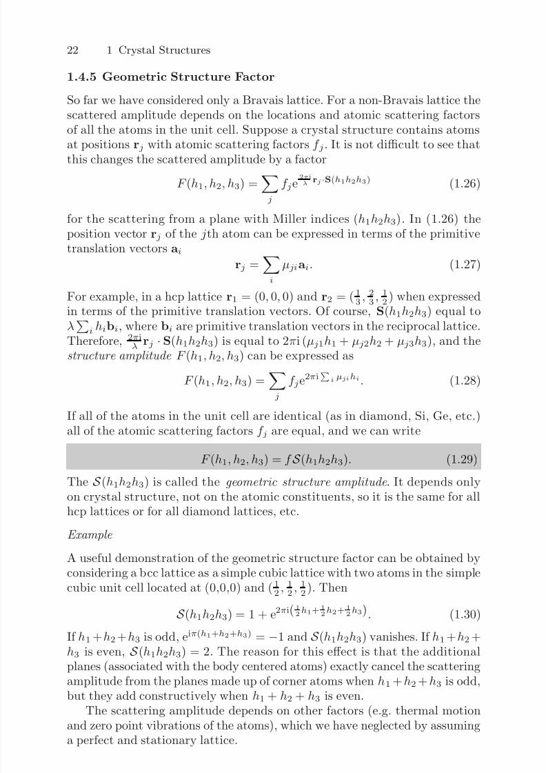
In this method a single crystal is held stationary in a beam of continuous wavelength X-ray radiation (Fig. 1.22). Various crystal planes select the appropri-ate wave length for constructive interference, and a geometric arrangement of bright spots is obtained on a film.
Rotating Crystal Method
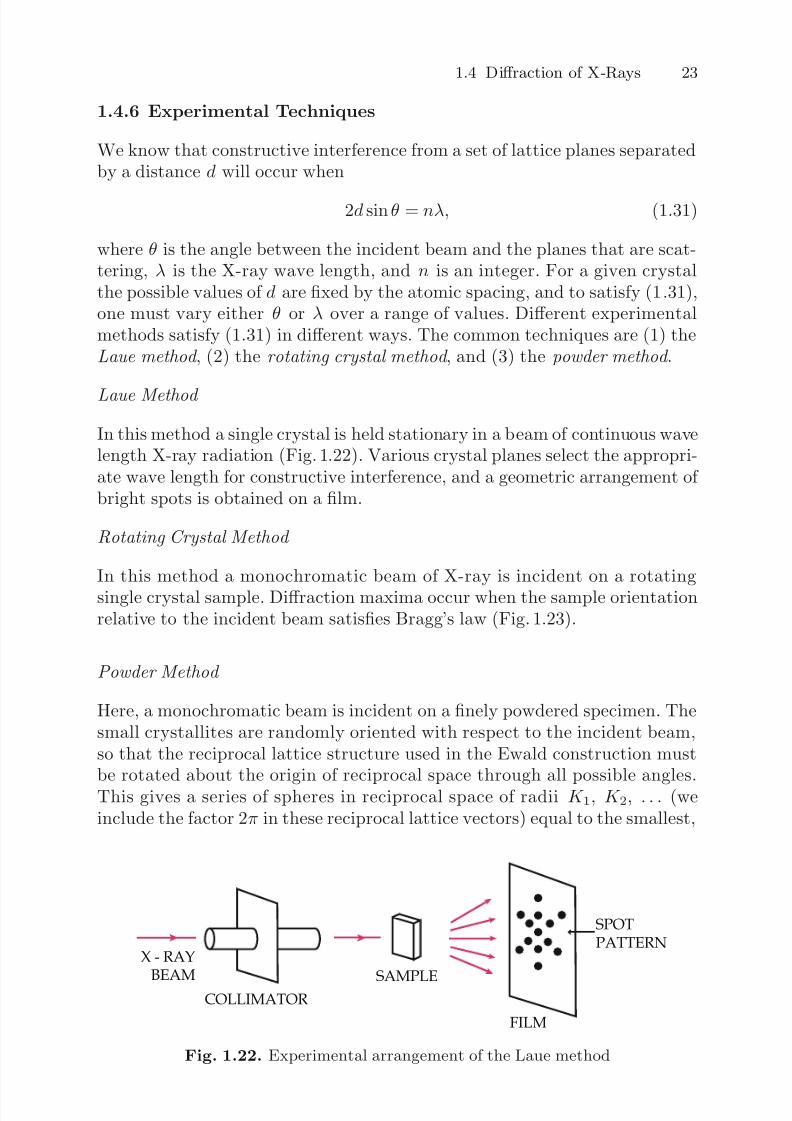
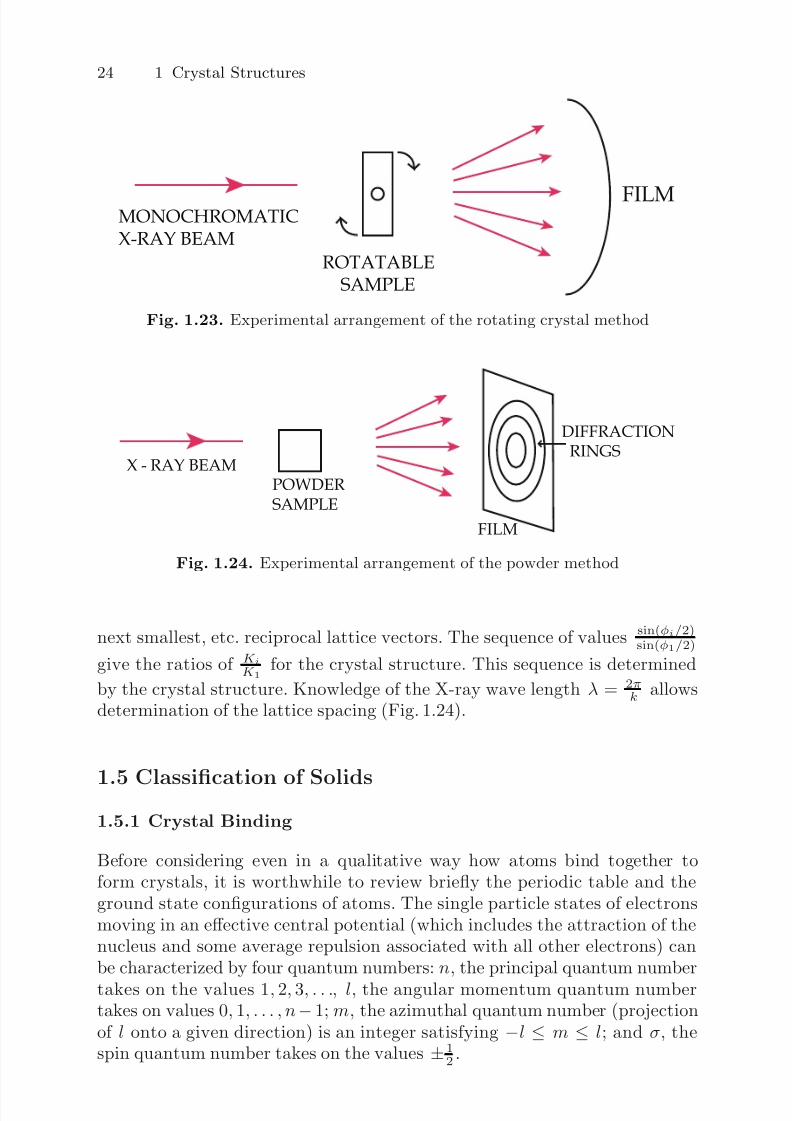
In this method a monochromatic beam of X-ray is incident on a rotatingsingle crystal sample. Diffraction maxima occur when the sample orientationrelative to the incident beam satisfies Bragg’s law (Fig. 1.23).
Powder Method
Here, a monochromatic beam is incident on a finely powdered specimen. Thesmall crystallites are randomly oriented with respect to the incident beam,so that the reciprocal lattice structure used in the Ewald construction mustbe rotated about the origin of reciprocal space through all possible angles.This gives a series of spheres in reciprocal space of radii K 1, K 2, . . . (weinclude the factor 2π in these reciprocal lattice vectors) equal to the smallest,
COLLIMATOR
SAMPLE
FILM
X - RAY
BEAM
SPOT
PATTERN
Fig. 1.22. Experimental arrangement of the Laue method
7/26/2019 ch1introduction solid state physics
http://slidepdf.com/reader/full/ch1introduction-solid-state-physics 22/34
24 1 Crystal Structures
ROTATABLE
SAMPLE
MONOCHROMATIC
X-RAY BEAM
FILM
Fig. 1.23. Experimental arrangement of the rotating crystal method
POWDER
SAMPLE
FILM
X - RAY BEAM
DIFFRACTION
RINGS
Fig. 1.24. Experimental arrangement of the powder method
next smallest, etc. reciprocal lattice vectors. The sequence of values sin(φi/2)sin(φ1/2)
give the ratios of K iK 1
for the crystal structure. This sequence is determined
by the crystal structure. Knowledge of the X-ray wave length λ = 2πk allows
determination of the lattice spacing (Fig. 1.24).
1.5 Classification of Solids
1.5.1 Crystal Binding
Before considering even in a qualitative way how atoms bind together toform crystals, it is worthwhile to review briefly the periodic table and theground state configurations of atoms. The single particle states of electronsmoving in an effective central potential (which includes the attraction of thenucleus and some average repulsion associated with all other electrons) canbe characterized by four quantum numbers: n, the principal quantum number
takes on the values 1, 2, 3, . . ., l, the angular momentum quantum numbertakes on values 0, 1, . . . , n− 1; m, the azimuthal quantum number (projectionof l onto a given direction) is an integer satisfying −l ≤ m ≤ l; and σ, thespin quantum number takes on the values ±1
2 .
7/26/2019 ch1introduction solid state physics
http://slidepdf.com/reader/full/ch1introduction-solid-state-physics 23/34
1.5 Classification of Solids 25
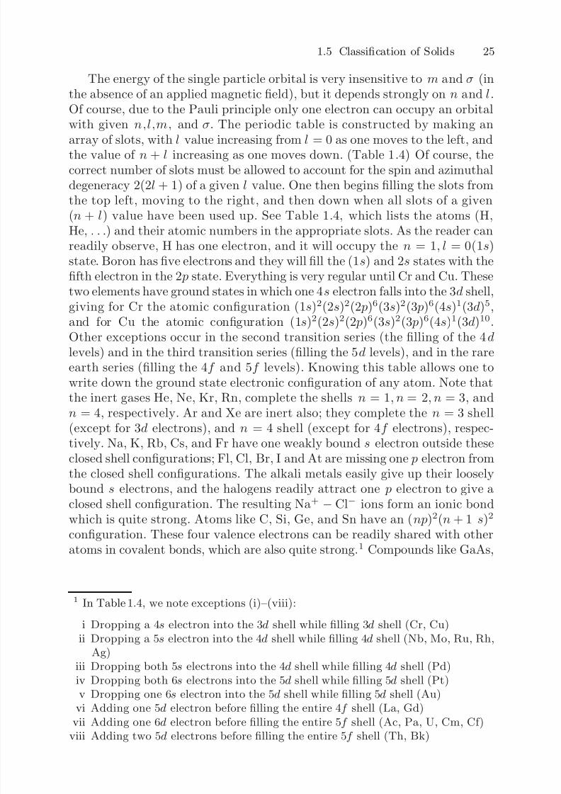
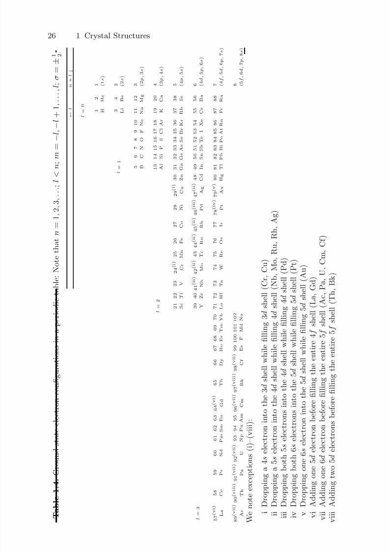
The energy of the single particle orbital is very insensitive to m and σ (inthe absence of an applied magnetic field), but it depends strongly on n and l.Of course, due to the Pauli principle only one electron can occupy an orbitalwith given n,l,m, and σ. The periodic table is constructed by making an
array of slots, with l value increasing from l = 0 as one moves to the left, andthe value of n + l increasing as one moves down. (Table 1.4) Of course, thecorrect number of slots must be allowed to account for the spin and azimuthaldegeneracy 2(2l + 1) of a given l value. One then begins filling the slots fromthe top left, moving to the right, and then down when all slots of a given(n + l) value have been used up. See Table 1.4, which lists the atoms (H,He, . . .) and their atomic numbers in the appropriate slots. As the reader canreadily observe, H has one electron, and it will occupy the n = 1, l = 0(1s)state. Boron has five electrons and they will fill the (1s) and 2s states with the
fifth electron in the 2 p state. Everything is very regular until Cr and Cu. Thesetwo elements have ground states in which one 4s electron falls into the 3d shell,giving for Cr the atomic configuration (1s)2(2s)2(2 p)6(3s)2(3 p)6(4s)1(3d)5,and for Cu the atomic configuration (1s)2(2s)2(2 p)6(3s)2(3 p)6(4s)1(3d)10.Other exceptions occur in the second transition series (the filling of the 4dlevels) and in the third transition series (filling the 5d levels), and in the rareearth series (filling the 4f and 5f levels). Knowing this table allows one towrite down the ground state electronic configuration of any atom. Note thatthe inert gases He, Ne, Kr, Rn, complete the shells n = 1, n = 2, n = 3, and
n = 4, respectively. Ar and Xe are inert also; they complete the n = 3 shell(except for 3d electrons), and n = 4 shell (except for 4f electrons), respec-tively. Na, K, Rb, Cs, and Fr have one weakly bound s electron outside theseclosed shell configurations; Fl, Cl, Br, I and At are missing one p electron fromthe closed shell configurations. The alkali metals easily give up their looselybound s electrons, and the halogens readily attract one p electron to give aclosed shell configuration. The resulting Na+ − Cl− ions form an ionic bondwhich is quite strong. Atoms like C, Si, Ge, and Sn have an (np)2(n + 1 s)2
configuration. These four valence electrons can be readily shared with otheratoms in covalent bonds, which are also quite strong.1 Compounds like GaAs,
1 In Table 1.4, we note exceptions (i)–(viii):
i Dropping a 4s electron into the 3d shell while filling 3d shell (Cr, Cu)ii Dropping a 5s electron into the 4d shell while filling 4d shell (Nb, Mo, Ru, Rh,
Ag)iii Dropping both 5s electrons into the 4d shell while filling 4d shell (Pd)iv Dropping both 6s electrons into the 5d shell while filling 5d shell (Pt)
v Dropping one 6s electron into the 5d shell while filling 5d shell (Au)vi Adding one 5d electron before filling the entire 4f shell (La, Gd)
vii Adding one 6d electron before filling the entire 5f shell (Ac, Pa, U, Cm, Cf)viii Adding two 5d electrons before filling the entire 5f shell (Th, Bk)
7/26/2019 ch1introduction solid state physics
http://slidepdf.com/reader/full/ch1introduction-solid-state-physics 24/34
26 1 Crystal Structures
T a b l e 1 . 4
. G r o u n d s t a t e e l e c t r o n c o n
fi g u r a t i o n s i n a p e r i o d i c t a b l e : N o t e t h a t n =
1 , 2 , 3 , . . . ;
l < n ; m
= −
l , −
l + 1 , . . . ,
l ; σ = ±
1 2
←
l
n
+ l ↓
l =
0 1 H
2 H e
1 ( 1 s
)
l =
1
3 L i
4 B e
2 ( 2 s
)
5 B
6 C
7 N
8 O
9 F
1 0
N e
1 1
N a
1 2 M g
3 ( 2 p ,
3 s
)
l =
2
1 3
A l
1 4 S
i 1 5 P
1 6 S 1 7
C l
1 8
A r
1 9 K
2 0 C a
4 ( 3 p ,
4 s
)
2 1
S c
2 2
T i
2 3 V
2 4
( i ) C r
2 5
M n
2 6
F e
2 7
C o
2 8
N i
2 9
( i )
C
u
3 0
Z n
3 1
G a
3 2
G e
3 3
A s
3 4
S e
3 5
B r
3 6
K r
3 7
R b
3 8 S r
5 ( 4 p ,
5 s
)
l =
3
3 9 Y
4 0
Z r 4
1 ( i i )
N b
4 2
( i i )
M o
4 3
T c
4 4
( i i )
R u
4 5
( i i )
R h
4 6
( i i i )
P d
4 7
( i i )
A
g
4 8
C d
4 9 I n
5 0
S n
5 1
S b
5 2
T e
5 3 I 5 4
X e
5 5
C s
5 6 B a
6 ( 4 d ,
5 p ,
6 s
)
5 7
( v i )
L a
5 8
C e
5 9
P r
6 0
N d
6 1
P m
6 2
S m
6 3
E u
6 4
( v i )
G d
6 5
T b
6 6
D y
6 7
H o
6 8
E r
6 9
T m
7 0
Y b
7 1
L u
7 2
H f
7 3
T a
7 4
W
7 5
R e
7 6
O s
7 7 I r
7 8
( i v )
P t
7 9
( v )
A
u
8 0
H g
8 1
T l
8 2
P b
8 3
B i
8 4
P o
8 5
A t
8 6
R n
8 7 F
r
8 8 R a
7 ( 4 f ,
5 d ,
6 p ,
7 s
)
8 9
( v i i )
A c
9 0
( v i i i )
T h
9 1
( v i i )
P a
9 2
( v i i )
U
9 3
N p
9 4
P u
9 5
A m
9 6
( v i i )
C m
9 7 ( v i i i )
B k
9 8
( v i i )
C f
9 9
E s
1 0 0
F
1 0 1
M d
1 0 2
N o
8 ( 5 f ,
6 d ,
7 p ,
8 s
)
W e n o t e e x c e p t i o n s ( i ) – ( v i i i ) :
i D r o p p i n g a 4 s e l e c t r o n i n t o t h e 3 d
s h e l l w h i l e fi l l i n g 3 d s h e l l ( C r , C u )
i i D r o p p i n g a 5 s e l e c t r o n i n t o t h e 4 d
s h e l l w h i l e fi l l i n g 4 d s h e l l ( N b ,
M o , R u ,
R h ,
A g )
i i i D r o p p i n g b o t h 5 s e l e c t r o n s i n t o t h
e 4 d s h e l l w h i l e fi l l i n g 4 d s h e l l ( P d )
i v D r o p p i n g b o t h 6 s e l e c t r o n s i n t o t h
e 5 d s h e l l w h i l e fi l l i n g 5 d s h e l l ( P t )
v D r o p p i n g o n e 6 s e l e c t r o n i n t o t h e
5 d s h e l l w h i l e fi l l i n g 5 d s h e l l ( A u )
v i A d d i n g
o n e 5 d e l e c t r o n b e f o r e fi l l i n g t h e e n t i r e 4 f s h e l l ( L a , G
d )
v i i A d d i n g
o n e 6 d e l e c t r o n b e f o r e fi l l i n g t h e e n t i r e 5 f s h e l l ( A c , P
a , U ,
C m ,
C f )
v i i i A d d i n g
t w o 5 d e l e c t r o n s b e f o r e fi l l i n g t h e e n t i r e 5 f s h e l l ( T h ,
B k )

7/26/2019 ch1introduction solid state physics
http://slidepdf.com/reader/full/ch1introduction-solid-state-physics 25/34
1.6 Binding Energy of Ionic Crystals 27
GaP, GaSb, or InP, InAs, InSb, etc., are formed from column III and columnV constituents. With the partial transfer of an electron from As to Ga, oneobtains the covalent bonding structure of Si or Ge as well as some degree of ionicity as in NaCl. Metallic elements like Na and K are relatively weakly
bound. Their outermost s electrons become almost free in the solid and act asa glue holding the positively charged ions together. The weakest bonding insolids is associated with weak Van der Waals coupling between the constituentatoms or molecules. To give some idea of the binding energy of solids, we willconsider the binding of ionic crystals like NaCl or CsCl.
1.6 Binding Energy of Ionic Crystals
The binding energy of ionic crystals results primarily from the electrostaticinteraction between the constituent ions. A rough order of magnitude estimateof the binding energy per molecule can be obtained by simply evaluating
V = e2
R0=
4.8 × 10⁻¹⁰esu
2
2.8 × 10⁻⁸cm 8 × 10⁻¹²ergs ∼ 5eV.
Here, R0 is the observed interatomic spacing (which we take as 2.8 A, thespacing in NaCl). The experimentally measured value of the binding energy
of NaCl is almost 8 eV per molecule, so our rough estimate is not too bad.
Interatomic Potential
For an ionic crystal, the potential energy of a pair of atoms i, j can be takento be
φij = ± e2
rij+ λ
rnij. (1.32)
Here, rij is the distance between atoms i and j. The ± sign depends on
whether the atoms are like (+) or unlike (−). The first term is simply theCoulomb potential for a pair of point charges separated by rij . The secondterm accounts for core repulsion . The atoms or ions are not point charges, andwhen a pair of them gets close enough together their core electrons can repelone another. This core repulsion is expected to decrease rapidly with increas-ing rij . The parameters λ and n are phenomenological; they are determinedfrom experiment.
Total Energy
The total potential energy is given by
U = 1
2
i=j
φij . (1.33)
7/26/2019 ch1introduction solid state physics
http://slidepdf.com/reader/full/ch1introduction-solid-state-physics 26/34
28 1 Crystal Structures
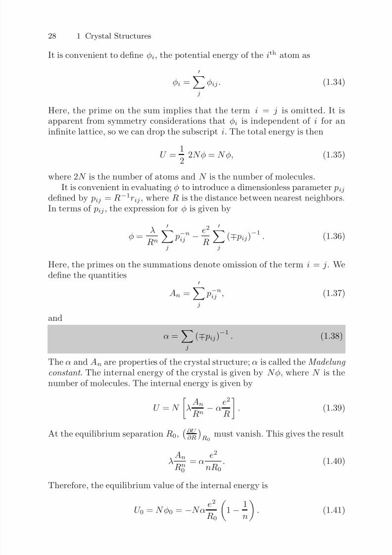
It is convenient to define φi, the potential energy of the ith atom as
φi =
j φij . (1.34)
Here, the prime on the sum implies that the term i = j is omitted. It isapparent from symmetry considerations that φi is independent of i for aninfinite lattice, so we can drop the subscript i. The total energy is then
U = 1
2 2Nφ = Nφ, (1.35)
where 2N is the number of atoms and N is the number of molecules.It is convenient in evaluating φ to introduce a dimensionless parameter pij
defined by pij = R−1rij , where R is the distance between nearest neighbors.In terms of pij , the expression for φ is given by
φ = λ
Rn
j
p−nij − e2
R
j
(∓ pij)−1 . (1.36)
Here, the primes on the summations denote omission of the term i = j. Wedefine the quantities
An =
j p−nij , (1.37)
and
α =j
(∓ pij)−1
. (1.38)
The α and An are properties of the crystal structure; α is called the Madelung
constant . The internal energy of the crystal is given by Nφ, where N is thenumber of molecules. The internal energy is given by
U = N
λAn
Rn − α
e2
R
. (1.39)
At the equilibrium separation R0,∂U ∂R
R0
must vanish. This gives the result
λAn
Rn0
= α e2
nR0. (1.40)
Therefore, the equilibrium value of the internal energy is
U 0 = Nφ0 = −Nα e2
R0
1 − 1
n
. (1.41)
7/26/2019 ch1introduction solid state physics
http://slidepdf.com/reader/full/ch1introduction-solid-state-physics 27/34
1.6 Binding Energy of Ionic Crystals 29
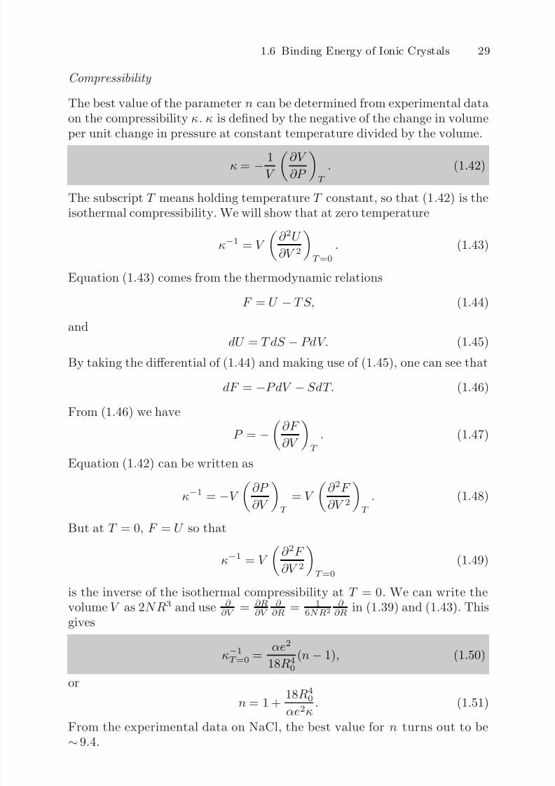
Compressibility
The best value of the parameter n can be determined from experimental dataon the compressibility κ. κ is defined by the negative of the change in volume
per unit change in pressure at constant temperature divided by the volume.
κ = − 1
V
∂V
∂P
T
. (1.42)
The subscript T means holding temperature T constant, so that (1.42) is theisothermal compressibility. We will show that at zero temperature
κ−1 = V
∂ 2U
∂V 2
T =0
. (1.43)
Equation (1.43) comes from the thermodynamic relations
F = U − TS, (1.44)
anddU = T dS − PdV. (1.45)
By taking the differential of (1.44) and making use of (1.45), one can see that
dF = −PdV − SdT. (1.46)
From (1.46) we haveP = −
∂F
∂V
T
. (1.47)
Equation (1.42) can be written as
κ−1 = −V ∂P
∂V
T
= V
∂ 2F
∂V 2
T
. (1.48)
But at T = 0, F = U so that
κ−1 = V ∂ 2F ∂V 2
T =0
(1.49)
is the inverse of the isothermal compressibility at T = 0. We can write thevolume V as 2NR3 and use ∂
∂V = ∂R∂V
∂ ∂R = 1
6NR2
∂ ∂R in (1.39) and (1.43). This
gives
κ−1T =0 =
αe2
18R40
(n− 1), (1.50)
orn = 1 +
18R40
αe2κ. (1.51)
From the experimental data on NaCl, the best value for n turns out to be∼ 9.4.
7/26/2019 ch1introduction solid state physics
http://slidepdf.com/reader/full/ch1introduction-solid-state-physics 28/34
30 1 Crystal Structures
Evaluation of the Madelung Constant
For simplicity let us start with a linear chain. Each positive (+) atom has twoneighbors, which are negative (−) atoms, at p01 = 1. Therefore,
α =j
∓ p−1ij = 2
1 − 1
2 +
1
3 − 1
4 + . . .
. (1.52)
If you remember that the power series expansion for ln(1 + x) is given by
−∞n=1
(−x)n
n = x − x2
2 + x3
3 − x4
4 + · · · and is convergent for x ≤ 1, it isapparent that
α = 2ln 2. (1.53)
If we attempt the same approach for NaCl, we obtain
α = 6
1 − 12√
2+
8√ 3
− 6
2 + · · · . (1.54)
This is taking six opposite charge nearest neighbors at a separation of onenearest neighbor distance, 12 same charge next nearest neighbors at
√ 2 times
that distance, etc. It is clear that the series in (1.54) converges very poorly.The convergence can be greatly improved by using a different counting pro-cedure in which one works with groups of ions which form a more or less
neutral array. The motivation is that the potential of a neutral assembly of charges falls off much more quickly with distance than that of a chargedassembly.
Evjen’s Method
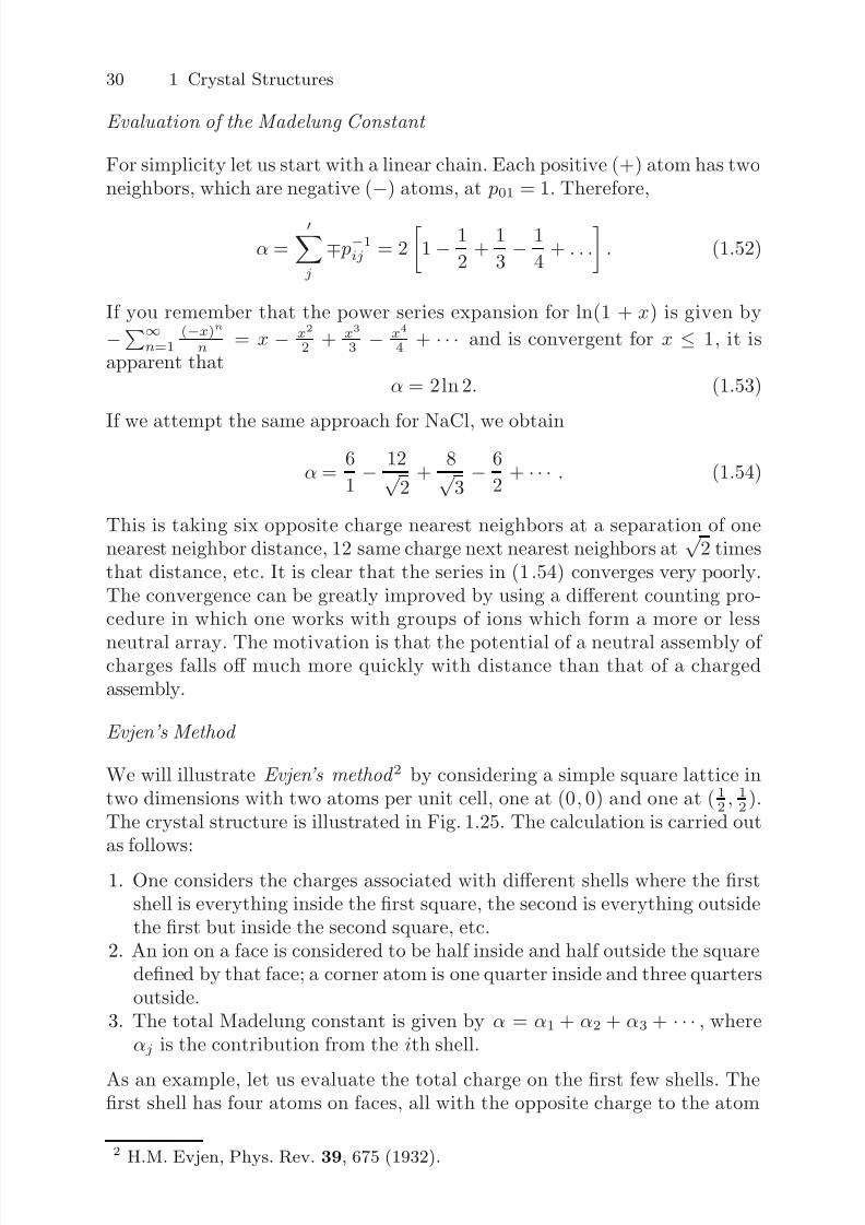
We will illustrate Evjen’s method 2 by considering a simple square lattice intwo dimensions with two atoms per unit cell, one at (0, 0) and one at ( 1
2, 1
2).
The crystal structure is illustrated in Fig. 1.25. The calculation is carried outas follows:
1. One considers the charges associated with different shells where the firstshell is everything inside the first square, the second is everything outsidethe first but inside the second square, etc.
2. An ion on a face is considered to be half inside and half outside the squaredefined by that face; a corner atom is one quarter inside and three quartersoutside.
3. The total Madelung constant is given by α = α1 + α2 + α3 + · · · , whereαj is the contribution from the ith shell.
As an example, let us evaluate the total charge on the first few shells. Thefirst shell has four atoms on faces, all with the opposite charge to the atom
2 H.M. Evjen, Phys. Rev. 39, 675 (1932).
7/26/2019 ch1introduction solid state physics
http://slidepdf.com/reader/full/ch1introduction-solid-state-physics 29/34
1.6 Binding Energy of Ionic Crystals 31
PRIMITIVE
UNIT CELL
Fig. 1.25. Evjen method for a simple square lattice in two dimensions
at the origin and four corner atoms all with the same charge as the atom atthe origin. Therefore, the charge of shell number one is
Q1 = 4
1
2
− 4
1
4
= 1. (1.55)
Doing the same for the second shell gives
Q2 = 4
1
2
− 4
3
4
− 4
1
2
+ 8
1
2
− 4
1
4
= 0. (1.56)
Here the first two terms come from the remainder of the atoms on the outsideof the first square; the next three terms come from the atoms on the inside of the second square. To get α1 and α2 we simply divide the individual chargesby their separations from the origin. This gives
α1 = 4 ( 1
2 )
1 − 4 ( 1
4 )√ 2
1.293, (1.57)
α2 = 4 ( 1
2 )
1 − 4 ( 3
4 )√ 2
− 4 ( 12 )
2 +
8 ( 12 )√ 5
+ 4 ( 1
4 )
2√
2 0.314. (1.58)
This gives α α1 + α2 ∼ 1.607. The readers should be able to evaluate α3
for themselves.
Madelung Constant for Three-Dimensional Lattices
For a three-dimensional crystal, Evjen’s method is essentially the same withthe exception that
7/26/2019 ch1introduction solid state physics
http://slidepdf.com/reader/full/ch1introduction-solid-state-physics 30/34
32 1 Crystal Structures
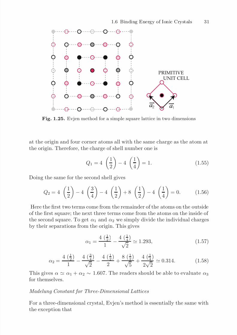
Fig. 1.26. Central atom and the first cube of the Evjen method for the NaClstructure
1. The squares are replaced by cubes.2. Atoms on the face of a cube are considered to be half inside and half outside
the cube; atoms on the edge are 14 inside and 3
4 outside, and corner atomsare 1
8 inside and 78 outside.
We illustrate the case of the NaCl structure as an example in the threedimensions (see Fig. 1.26).For α1 we obtain
α1 = 6 ( 1
2 )
1 − 12 ( 1
4 )√ 2
+ 8 ( 1
8 )√ 3
1.456. (1.59)
For α2 we have the following contributions:
1. Remainder of the contributions from the atoms on the first cube
=
6 ( 12
)
1 − 12 ( 3
4)
√ 2 +
8 ( 78
)
√ 32. Atoms on the interior of faces of the second cube
= − 6 ( 12
)
2 + 6(4) ( 1
2)√
5 − 6(4) ( 1
2)√
6
3. Atoms on the interior of edges of the second cube
= − 12 ( 14
)√ 8
+ 12(2) ( 1
4)√
9
4. Atoms on the interior of the coners of the second cube
= − 8 ( 18
)√ 12
Adding them together gives
α2 =
3 − 9√
2+
7√ 3
+
−3
2 +
12√ 5
− 12√ 6
+
− 3√
8+
6
3
− 1√
12 0.295.
(1.60)
7/26/2019 ch1introduction solid state physics
http://slidepdf.com/reader/full/ch1introduction-solid-state-physics 31/34
1.6 Binding Energy of Ionic Crystals 33
Thus, to the approximation α α1 + α2 we find that α 1.752. The exactresult for NaCl is α = 1.747558 . . ., so Evjen’s method gives a surprisinglyaccurate result after only two shells.
Results of rather detailed evaluations of α for several different crystal struc-
tures are α(NaCl) = 1.74756, α(CsCl) = 1.76267, α(zincblende) = 1.63806,α(wurtzite) = 1.64132. The NaCl structure occurs much more frequently thanthe CsCl structure. This may seem a bit surprising since α(CsCl) is about 1%larger than α(NaCl). However, core repulsion accounts for about 10% of thebinding energy (see (1.41)). In the CsCl structure, each atom has eight nearestneighbors instead of the six in NaCl. This should increase the core repulsionby something of the order of 25% in CsCl. Thus, we expect about 2 .5% largercontribution (from core repulsion) to the binding energy of CsCl. This negativecontribution to the binding energy more than compensates the 1% difference
in Madelung constants.
7/26/2019 ch1introduction solid state physics
http://slidepdf.com/reader/full/ch1introduction-solid-state-physics 32/34
34 1 Crystal Structures
Problems
1.1. Demonstrate that
(a) The reciprocal lattice of a simple cubic lattice is simple cubic.(b) The reciprocal lattice of a body centered cubic lattice is a face centered
cubic lattice.(c) The reciprocal lattice of a hexagonal lattice is hexagonal.
1.2. Determine the packing fraction of
(a) A simple cubic lattice(b) A face centered lattice(c) A body centered lattice
(d) The diamond structure(e) A hexagonal close packed lattice with an ideal ca ratio(f) The graphite structure with an ideal ca .
1.3. The Bravais lattice of the diamond structure is fcc with two carbon atomsper primitive unit cell. If one of the two basis atoms is at (0,0,0), then theother is at ( 1
4, 1
4, 1
4).
(a) Illustrate that a reflection through the (100) plane followed by a non-primitive translation through [ 1
4 , 14 ,
14 ] is a glide-plane operation for the
diamond structure.(b) Illustrate that a fourfold rotation about an axis in diamond parallel tothe x-axis passing through the point (1, 1
4, 0) (the screw axis) followed
by the translation [ 14 , 0, 0] parallel to the screw axis is a screw operation
for the diamond structure.
1.4. Determine the group multiplication table of the point group of anequilateral triangle.
1.5. CsCl can be thought of as a simple cubic lattice with two different atoms
[at (0, 0, 0) and ( 12 , 12 , 12 )] in the cubic unit cell. Let f + and f − be the atomicscattering factors of the two constituents.
(a) What is the structure amplitude F (h1, h2, h3) for this crystal?(b) An X-ray source has a continuous spectrum with wave numbers k
satisfying: k is parallel to the [110] direction and 2−1/2
2πa
≤ |k| ≤3 × 21/2
2πa
, where a is the edge distance of the simple cube. Use the
Ewald construction for a plane that contains the direction of incidenceto show which reciprocal lattice points display diffraction maxima.
(c) If f + = f −
, which of these maxima disappear?
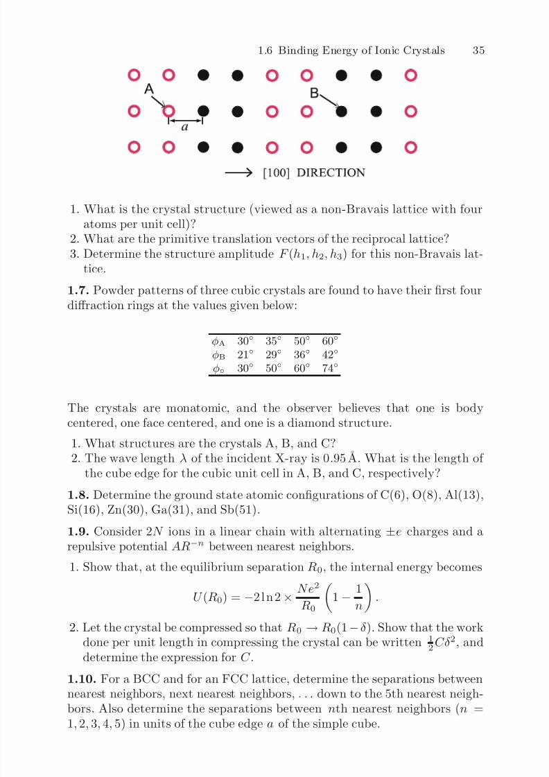
1.6. A simple cubic structure is constructed in which two planes of A atomsfollowed by two planes of B atoms alternate in the [100] direction.
7/26/2019 ch1introduction solid state physics
http://slidepdf.com/reader/full/ch1introduction-solid-state-physics 33/34
7/26/2019 ch1introduction solid state physics
http://slidepdf.com/reader/full/ch1introduction-solid-state-physics 34/34
36 1 Crystal Structures
Summary
In this chapter first we have introduced basic geometrical concepts useful indescribing periodic arrays of objects and crystal structures both in real and
reciprocal spaces assuming that the atoms sit at lattice sites.A lattice is an infinite array of points obtained from three primitive
translation vectors a1, a2, a3. Any point on the lattice is given by
n = n1a1 + n2a2 + n3a3.
Any pair of lattice points can be connected by a vector of the form
Tn1n2n3 = n1a1 + n2a2 + n3a3.
Well defined crystal structure is an arrangement of atoms in a lattice suchthat the atomic arrangement looks absolutely identical when viewed from twodifferent points that are separated by a lattice translation vector . Allowedtypes of Bravais lattices are discussed in terms of symmetry operationsboth in two and three dimensions. Because of the requirement of transla-tional invariance under operations of the lattice translation, the rotations of 60◦, 90◦, 120◦, 180◦, and 360◦ are allowed.
If there is only one atom associated with each lattice point, the latticeof the crystal structure is called Bravais lattice . If more than one atom is
associated with each lattice point, the lattice is called a lattice with a basis .If a1, a2, a3 are the primitive translations of some lattice, one can define a setof primitive translation vectors b1,b2,b3 by the condition
ai · bj = 2πδ ij ,
where δ ij = 0 if i is not equal to j and δ ii = 1. It is easy to see that
bi = 2π aj × ak
ai
·(aj
×ak)
,
where i, j, and k are different. The lattice formed by the primitive transla-tion vectors b1,b2,b3 is called the reciprocal lattice (reciprocal to the latticeformed by a1,a2,a3), and a reciprocal lattice vector is given by
Gh1h2h3 = h1b1 + h2b2 + h3b3.
Simple crystal structures and principles of commonly used experimentalmethods of wave diffraction are also reviewed briefly. Connection of Laueequations and Bragg’s law is shown. Classification of crystalline solids arethen discussed according to configuration of valence electrons of the elementsforming the solid.