ch.6 ofdm principles - mercury.kau.ac.krmercury.kau.ac.kr/hrpark/lecture/2012년...
TRANSCRIPT

CH.6 OFDM Principles
1Korea Aerospace University Mobile Communications Lab.
CH.6 OFDM Principles

Contents
� Overview of the OFDM Technique
� Block Diagram of an OFDM Transceiver
� Generation of Sub-carriers Using the IFFT
� Demodulation Using the FFT
� Guard Time and Cyclic Extension
� Windowing
2Korea Aerospace University Mobile Communications Lab.
� Windowing
� Design Example of OFDM Systems
� OFDM-based Multiple Access Schemes

Overview of the OFDM Technique [1],[2]
� Recently, mobile internet and multimedia services rapidly increase
==> High rate data transmission is essential!
� In case of transmitting high rate data through single carrier systems,
the ISI (inter-symbol interference) is inevitable due to the channel
delay spread, as shown in Fig. 6.1.
� The inter-symbol interference can be reduced by multi-carrier
transmission which divides a high speed data stream into several
parallel lower rate data streams prior to transmission.
3Korea Aerospace University Mobile Communications Lab.
parallel lower rate data streams prior to transmission.
� OFDM (orthogonal frequency division multiplexing) is a special case
of multi-carrier transmission techniques that the spectra of sub-
carriers are overlapped.
� OFDM is the only transmission technique accepted for the fourth
generation mobile communication systems:
� WCDMA-LTE
� WiBro evolution (IEEE 802.16m)
� UMB (Ultra Mobile Broadband, IEEE 802.20)

Overview of the OFDM Technique (cont.)
4Korea Aerospace University Mobile Communications Lab.
Fig. 6.1 Illustration of the inter-symbol interference due to delay spread

Overview of the OFDM Technique (cont.)
� In a classical multi-carrier transmission, the total frequency band
is divided into N non-overlapping frequency sub-channels
==> may reduce the spectrum efficiency due to the guard band and
may require several oscillators and pulse-shaping filters.
5Korea Aerospace University Mobile Communications Lab.
Fig. 6.2 A classical multi-carrier transmission scheme

Overview of the OFDM Technique (cont.)
� In OFDM, however, the spectra of sub-carriers are overlapped ==>
no guard band and no pulse-shaping
f
6Korea Aerospace University Mobile Communications Lab.
0f
1Kf −2f1f0f
1Kf −2f1f
f
f
Fig. 6.3 Spectra of multi-carrier signals and OFDM signals

Overview of the OFDM Technique (cont.)
� The sub-carriers in OFDM signals are arranged so that the
sidebands of individual sub-carriers overlap but the signals are
received without inter-channel (or -carrier) interference (ICI).
7Korea Aerospace University Mobile Communications Lab.
Fig. 6.4 Spectra of an OFDM sub-channel and total OFDM channel
(a) Spectrum of an OFDM sub-channel (b) Spectrum of total OFDM channel

Overview of the OFDM Technique (cont.)
� Key advantages of OFDM
� Robust against inter-symbol interference
� Reduced H/W complexity since it does not require complicated equalizers
and pulse-shaping filters
� Can be implemented easily by using FFT / IFFT processors
� Drawbacks compared with a single carrier transmission
� Relatively large PAPR (peak-to-average power ratio) ==> reduced
8Korea Aerospace University Mobile Communications Lab.
� Relatively large PAPR (peak-to-average power ratio) ==> reduced
efficiency of the power amplifier
� More sensitive to the frequency offset and phase noise
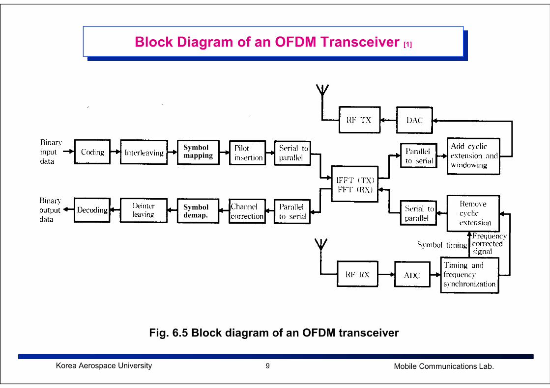
Block Diagram of an OFDM Transceiver [1]
Symbolmapping
9Korea Aerospace University Mobile Communications Lab.
Fig. 6.5 Block diagram of an OFDM transceiver
Symboldemap.
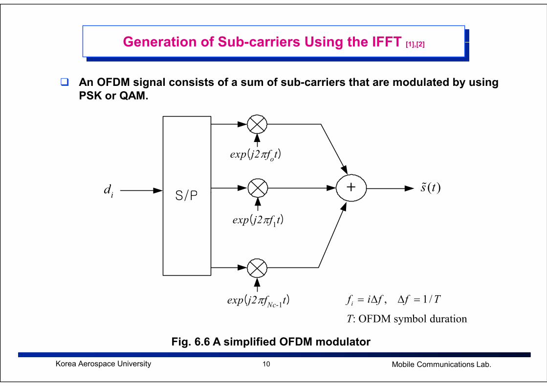
Generation of Sub-carriers Using the IFFT [1],[2]
S/P+d
i
exp(j2πfot)
( )s tɶ
� An OFDM signal consists of a sum of sub-carriers that are modulated by using
PSK or QAM.
10Korea Aerospace University Mobile Communications Lab.
Fig. 6.6 A simplified OFDM modulator
S/P+d
i
exp(j2πf1t)
exp(j2πfNc-1t)
( )s tɶ
, 1 /if i f f T= ∆ ∆ =
T: OFDM symbol duration

Generation of Sub-carriers Using the IFFT (cont.)
� A complex baseband OFDM signal can be written as
( )1
0
( ) exp 2 , 0
( ) 0, 0 or
cN
i
i
s t d j i ft t T
s t t t T
π−
=
= ∆ ≤ ≤
= < >
∑ɶ
ɶ
( )s tɶ
11Korea Aerospace University Mobile Communications Lab.
id cN
T f∆
: complex PSK or QAM symbols, : number of used sub-carriers
: effective OFDM symbol duration, : sub-carrier spacing

Generation of Sub-carriers Using the IFFT (cont.)
� The complex baseband signal is in fact nothing more than the inverse Fourier
transform of N input symbols.
Let Then,, 0, 1, 2, , 1.t n t n N= ∆ = −⋯
( )
( )
1
0
1
( ) exp 2
exp 2 / , ( 1/ )
c
c
N
i
i
N
i
s n t d j i fn t
d j in t T f T
π
π
−
=
−
∆ = ∆ ∆
= ∆ ∆ =
∑
∑
ɶ
12Korea Aerospace University Mobile Communications Lab.
( )
( )
( )
{ }
0
1
0
1
0
exp 2 / , ( 1/ )
exp 2 / , ( )
exp 2 / , 0 for , 1, ,
sample of the IDFT of , : DFT
c
i
i
N
i
i
N
i i c c
i
i
d j in t T f T
d j in N T N t
d j in N d i N N N
N nth d N
π
π
π
=
−
=
−
=
= ∆ ∆ =
= = ∆
= = = +
⇒ ×
∑
∑
∑ ⋯
size
� Note that Nc is the number of used subcarriers, while N is the DFT size.

Generation of Sub-carriers Using the IFFT (cont.)
� The amplitude spectrum of the square pulse with a duration T is equal to the
sinc function, which has zeros for all frequencies f that are integer multiples
of 1/T.
� At the maximum of each sub-carrier spectrum, all other sub-carrier spectra are
zero.
13Korea Aerospace University Mobile Communications Lab.
Fig. 6.7 Spectra of the individual sub-carriers

Demodulation Using the FFT [1],[2]
� Demodulation is equivalent to DFT.
� Orthogonality between sub-carriers
� Each sub-carrier has exactly an integer number of cycles in the interval T.
� The number of cycles between adjacent sub-carriers differs by exactly one.
14Korea Aerospace University Mobile Communications Lab.
Fig. 6.8 Example of four sub-carriers within one OFDM symbol
0 T

Demodulation Using the FFT (cont.)
� Demodulation for the sub-carrier k
1
00th subcarrier
1
0 0
exp 2 exp 2
( )exp 2
c
c
T N
i
i
k
TN
i k
i
k itj t d j dt
T T
i kd j t dt d T
T
π π
π
−
=
−
=
−
− = =
∑∫
∑ ∫
�������
15Korea Aerospace University Mobile Communications Lab.
since
0 0iT
= ∫
0
0
( ) exp 2 , for
( )exp 2 0, for
T
T
i kj t dt T i k
T
i kj t dt i k
T
π
π
− = =
− = ≠
∫
∫
� Obviously, demodulation for all subcarriers can be performed by the FFT.
Guard Time and Cyclic Extension [1],[2]
� In order to avoid inter-symbol interference, a guard time should be introduced
for each OFDM symbol.
� The guard time should be chosen larger than the expected maximum multi-
path delay.
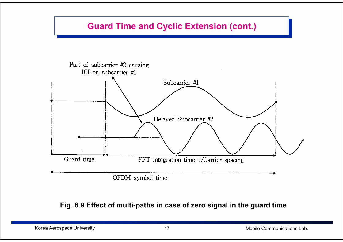
� The guard time could consist of no signal at all. However, in this case, the
problem of inter-carrier interference (ICI) would arise due to the loss of
orthogonality between sub-carriers, as shown in Fig. 6.9.
16Korea Aerospace University Mobile Communications Lab.
� To avoid the ICI, the OFDM symbol should be cyclically extended in the guard
time.
Guard Time and Cyclic Extension (cont.)
17Korea Aerospace University Mobile Communications Lab.
Fig. 6.9 Effect of multi-paths in case of zero signal in the guard time

Guard Time and Cyclic Extension (cont.)
copy
18Korea Aerospace University Mobile Communications Lab.
Fig. 6.10 OFDM symbol with cyclic extension
Guard Time and Cyclic Extension (cont.)
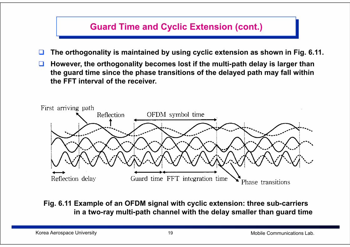
� The orthogonality is maintained by using cyclic extension as shown in Fig. 6.11.
� However, the orthogonality becomes lost if the multi-path delay is larger than
the guard time since the phase transitions of the delayed path may fall within
the FFT interval of the receiver.
19Korea Aerospace University Mobile Communications Lab.
Fig. 6.11 Example of an OFDM signal with cyclic extension: three sub-carriers
in a two-ray multi-path channel with the delay smaller than guard time

Guard Time and Cyclic Extension (cont.)
20Korea Aerospace University Mobile Communications Lab.
Fig. 6.12 16-QAM constellation for a 48-subcarrier OFDM link with a two-ray
multi-path channel, the second ray being 6dB lower than the first one
(a) delay < guard time, (b) delay exceeds 3% of the FFT interval
(c) delay exceeds 10% of the FFT interval

Windowing [1],[2]
� An OFDM signal consists of a number of unfiltered sub-carriers.
� Therefore, the out-of-band spectrum decreases rather slowly, with the speed
depending on the number of sub-carriers, as shown below.
21Korea Aerospace University Mobile Communications Lab.
Fig. 6.13 PSD without windowing for 16, 64, 256 sub-carriers
Windowing (cont.)
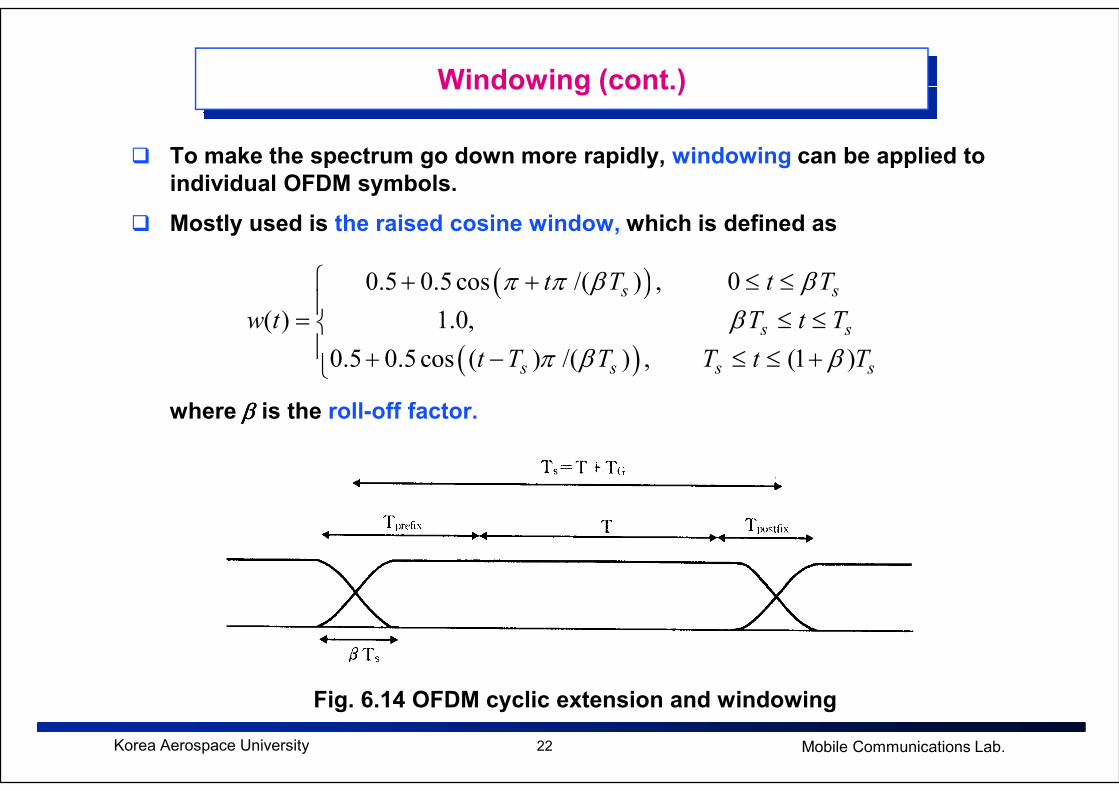
� To make the spectrum go down more rapidly, windowing can be applied to
individual OFDM symbols.
� Mostly used is the raised cosine window, which is defined as
( )
( )
0.5 0.5 cos /( ) , 0
( ) 1.0,
0.5 0.5 cos ( ) /( ) , (1 )
s s
s s
s s s s
t T t T
w t T t T
t T T T t T
π π β ββ
π β β
+ + ≤ ≤
= ≤ ≤ + − ≤ ≤ +
22Korea Aerospace University Mobile Communications Lab.
where ββββ is the roll-off factor.
Fig. 6.14 OFDM cyclic extension and windowing

Windowing (cont.)
23Korea Aerospace University Mobile Communications Lab.
Fig. 6.15 Spectra for raised cosine windowing with roll-off factor
0, 0.025, 0.05, and 0.1 (64 sub-carriers)
Windowing (cont.)
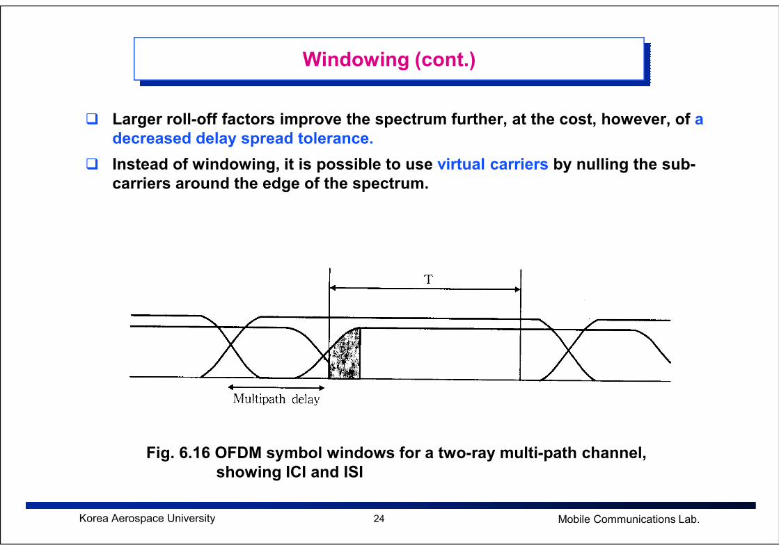
� Larger roll-off factors improve the spectrum further, at the cost, however, of a
decreased delay spread tolerance.
� Instead of windowing, it is possible to use virtual carriers by nulling the sub-
carriers around the edge of the spectrum.
24Korea Aerospace University Mobile Communications Lab.
Fig. 6.16 OFDM symbol windows for a two-ray multi-path channel,
showing ICI and ISI

Design Example of OFDM Systems [1]
� The choice of various OFDM parameters is a tradeoff between various, often
conflicting, requirements.
� Usually, there are three main requirements for the design of OFDM systems;
bandwidth, bit rate, and tolerable delay spread.
� As a first rule for design, the guard time should be at least four times the rms
delay spread.
� Also, to minimize the SNR loss caused by the guard time, it is desirable to
have the symbol duration much larger than the guard time.
25Korea Aerospace University Mobile Communications Lab.
have the symbol duration much larger than the guard time.
� However, a larger symbol duration means more sub-carriers with a smaller
sub-carrier spacing, a larger implementation complexity, and more sensitivity
to phase noise and frequency offset, as well as an increased peak-to-average
power ratio (PAPR).
� Hence, a practical design choice is to make the symbol duration around five
times the guard time.
� The number of sub-carriers may be determined by the required bit rate divided
by the bit rate per sub-carrier.

Design Example of OFDM Systems (cont.)
� As an example, suppose we want to design an OFDM system with the
following requirements.
� Bit rate: 20Mbps
� Tolerable delay spread: 200ns
� Bandwidth < 15MHz
- Guard time: delay spread x 4 = 800ns
- Total OFDM symbol duration: guard time (800ns) x 6 = 4.8µµµµs
26Korea Aerospace University Mobile Communications Lab.
- Total OFDM symbol duration: guard time (800ns) x 6 = 4.8µµµµs ==> FFT interval = 4.0µµµµs
- Sub-carrier spacing: 1/(4.0µµµµs) = 250kHz
- 15MHz / 250kHz = 60: number of used sub-carriers should be smaller than 60
- 20Mbps x 4.8us = 96bits per symbol
� 16-QAM, ½ coding: 48 sub-carriers are needed.
� QPSK without coding: 48 sub-carriers
� FFT size = 64

OFDM-Based Multiple Access Schemes
27Korea Aerospace University Mobile Communications Lab.
OFDM-TDMA OFDM-FDMA OFDM-CDMA (MC-CDMA)
Fig. 6.17 OFDM-based multiple access schemes
References
1. R. V. Nee and R. Prasad, OFDM for Wiress Multimedia Communications,
Artech House Publishers, 2000.
2. L. Hanjo, M. Munster, B. J. Choi, T. Keller, OFDM and MC-CDMA for
Broadband Multi-User Communications, WLANs, and Broadcasting, John
and Wiley, 2003.
28Korea Aerospace University Mobile Communications Lab.