chap1_introee_beta1313
DESCRIPTION
Introduction to basic principle of electric and electronics degree level for Electrical engineering courseTRANSCRIPT

BETA 1313
PRINCIPLES OF ELECTRIC &
ELECTRONICS
NAME: SUZIANA BINTI AHMAD
ROOM: FTK building / 1st Floor
PHONE: 06 – 2346585/ 019-6994023
E-MAIL: [email protected]

2
Lightning- The Ultimate Power From The Almighty (Extreme Voltage & Current)
Chapter 1: Introduction to Electricity & Electronics
• Electric energy sources, Electrical system, Electric
charge, Movement of electrons and current,
• EMF and potential difference, Electrical units,
Electrical measurement instrument,
• Symbols of electrical source and components,
Electrical simple connections and applications.

3
Chapter 1: Introduction to Electricity & Electronics
• Electric energy sources, Electrical system, Electric
charge, Movement of electrons and current,
• EMF and potential difference, Electrical units,
Electrical measurement instrument,
• Symbols of electrical source and components,
Electrical simple connections and applications.

4
EXPERIMENTAL SETUP : The beautiful of electricity…..but…

Chapter 1 5
Electrical system
CHAPTER 1:
INTRODUCTION TO ELECTRICITY &
ELECTRONICS
ELECTRICAL SYSTEM

6
ELECTRICITY SOURCES

Transmission Line
Chapter 1 7

Control Room
Chapter 1 8

Substation (Step up/ Step down)
Chapter 1 9
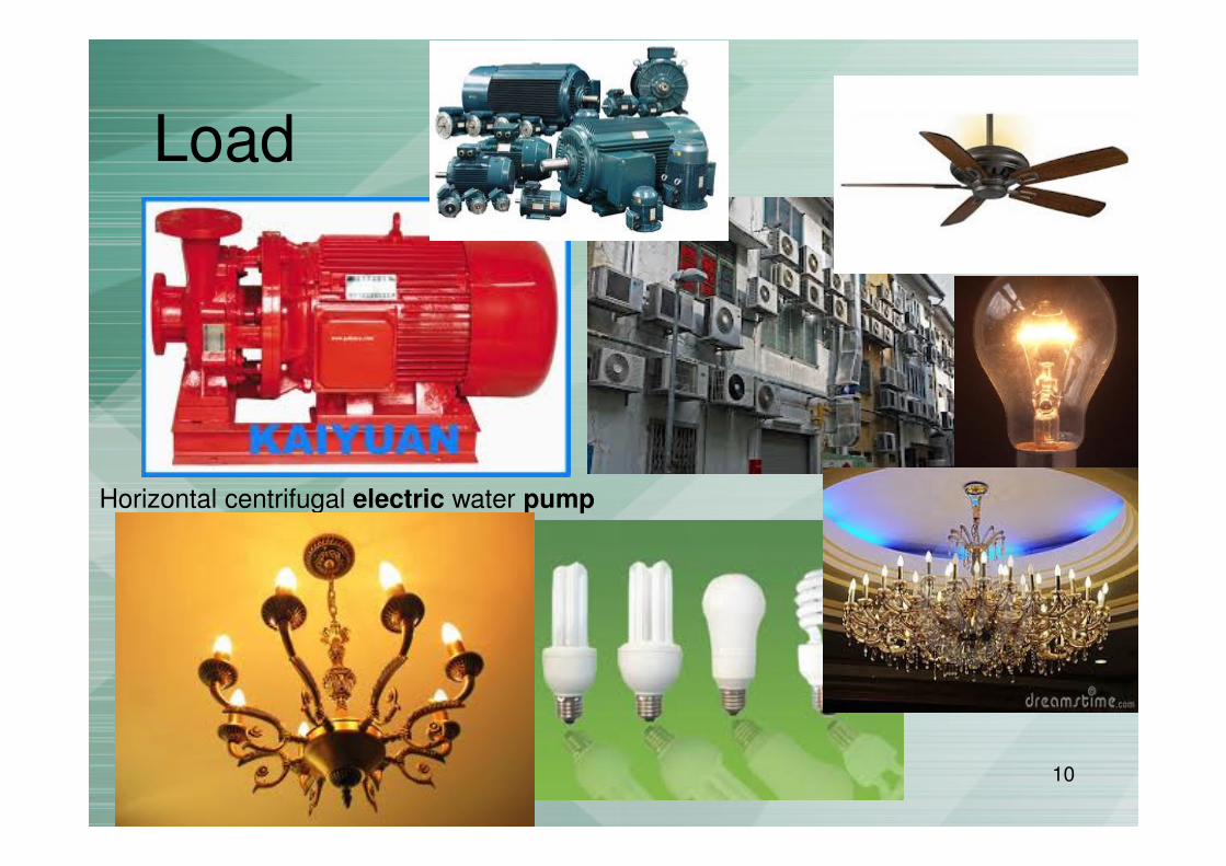
Load
Chapter 1 10
Horizontal centrifugal electric water pump

Chapter 1 11
ELECTRICAL SYSTEM contd.
• Electric circuit – an interconnection of electrical elements.
• Basic electrical system consists of 4 elements:
– Source - Provide electrical energy to electrical system (i.e DCor AC source). Can be obtain from battery, generator orsocket outlet.
– Transmission system - Conduct and transfer electrical energyfrom source to load (i.e insulated wire)
– Control - Control the flow of electrical energy (i.e switch).Permits the energy to flow or else interrupts the flow.
– Load - Absorb the electrical energy and perform a giventask/purpose/work. Most domestic electrical equipmentconstitutes loads (i.e motor)

Chapter 1 12
Torch Light system
Example: Simple System
ELECTRICAL SYSTEM contd.

Chapter 1 13
Electric Charge

Chapter 1 14
• All matter of substance is made up of molecules.
• Molecules – the smallest division of a substancethat could be made without destroying theidentity or properties of the substance.
• Atoms – the smallest particle of an element thatretains the characteristics of that element.
• Most molecules is made up of multiple atoms.
– Example:
• A molecule of hydrogen gas is a combination oftwo hydrogen atoms
ELECTRIC CHARGE contd.

Chapter 1 15
• a molecule of water is a combination of two hydrogenatoms and one oxygen atom.
Hydrogen gas molecule
Water molecule
ELECTRIC CHARGE contd.
Chapter 1 16
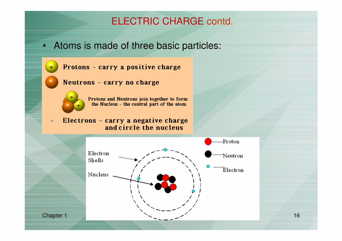
• Atoms is made of three basic particles:
ELECTRIC CHARGE contd.

Chapter 1 17
• Normally, atoms in balance or neutral condition
(# of protons = # of electrons).
• Some atoms hold their electrons loosely especially electron that islocated at valence shell (outermost shell).
– Easy to loose electron if there is force
• The loose electrons (free electron) can be transferred into anotheratoms.
• When an electron escapes from the atom – becomes positive ion
When atom acquire an electron – becomes negative ion.
ELECTRIC CHARGE contd.

Chapter 1 18
• A substance/materials that excess of electrons (negative ion) issaid to have negative charge.
Materials with deficiency of electrons (positive ion) is said tohave positive charge.
• Electrical charge – an electrical property of matter that existsbecause of an excess or defiency of electrons.
• Charges can be measured in coulomb
1 Coulomb (C) = 6.24 x 10¹⁸ electrons
1 electron = 1.602 x 10 -19 C
• Materials with charges of opposite polarity attracted.
Materials with charges of same polarity are repelled.
ELECTRIC CHARGE contd.

Chapter 1 19
• The force that attract or repel is called electric field.
• For opposite polarity of chargers, a certain amount ofenergy must be applied to overcome the attractionforce in order to move the opposite charges a distanceapart.
• The separation will create a potential energy betweenthe chargers.
• The difference in potential energy per charge is calledthe potential difference or voltage.
ELECTRIC CHARGE contd.

Chapter 1 20
• Three categories of materials are used in electronics:
– Conductor – a material that allows the free movement of
many electrons. Good conductor of electricity. Example:
copper, iron, silver…
– Insulator – a material that have no free electrons in their
structure. Example: rubber, glass…
– Semiconductors – elements that are neither true conductors
nor insulators in their ability to permit electrons to flow.
Also can be a basis for electronic devices such as diode,
transistor.
ELECTRIC CHARGE contd.

Chapter 1 21
VOLTAGE
• To move an electron in a conductor in a particular directionrequires some work or energy transfer.
• This work can be performed by an external force or called aselectromotive force (emf).
• This emf also known as potential difference or voltage.
• Voltage (V) is the energy required to move a unit chargethrough an element, measured in volts (V).
• Voltage is a measurement of potential between two points.
Chapter 1 22
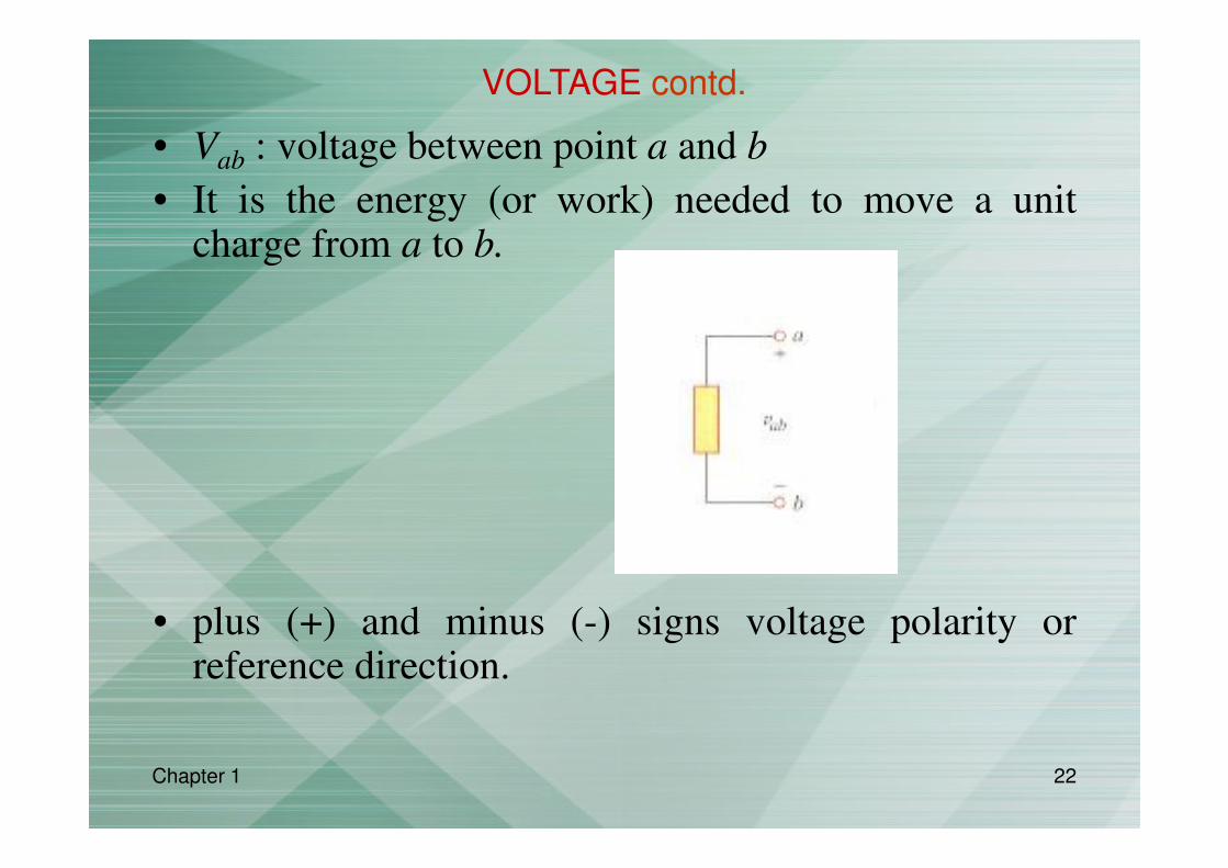
• Vab : voltage between point a and b
• It is the energy (or work) needed to move a unitcharge from a to b.
• plus (+) and minus (-) signs voltage polarity orreference direction.
VOLTAGE contd.

Chapter 1 23
• Voltage (V) is defined as energy/work per unit charge
V = W/Q
where V is voltage in volts(V), W is energy in joules (J) and Qis charge in coulombs (C).
• A voltage source is an that provides electrical energy orvoltage.
• Two types of voltage sources:
– dc voltage – a constant voltage with time. i.e. battery.
– ac voltage – a voltage that varies sinusoidally with time.
i.e. electric generator, socket outlet.
VOLTAGE contd.

Chapter 1 24
Current
• Voltage provides energy to electron, allowing them to move through a circuit.
• This movement of electrons is the current, which result in work being done in an electrical circuit.
• Consider the following:
– negative charges move from the negative terminal of battery towards the positive terminal.

Chapter 1 25
• Flow of current in metallic conductors is due to movement ofelectrons.
• However, it is universally accepted that current is the net flow ofpositive charges.
• There are two accepted conventions for the direction of electricalcurrent:
1. Electron flow direction – current is out of the negativeterminal of a voltage source, through the circuit and into thepositive terminal of the source.
2. Conventional current direction – current is out of thepositive terminal of a voltage source, through the circuit andinto the negative terminal of the source.
• The conventional current direction is used.
CURRENT contd.

Chapter 1 26
• Electric current – the time rate of change of charge, measured in amperes (A).
I = Q / t
where I is current in amperes(A), Q is charge in coulombs (C) and t is time in seconds.
• Generally, have two types of current:
– direct current (dc) – a current that remains constant with
time.
– alternating current (ac) – a current that varies sinusoidally
with time.
CURRENT contd.
Chapter 1 27
POWER & ENERGY
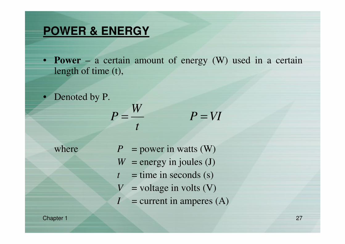
• Power – a certain amount of energy (W) used in a certainlength of time (t),
• Denoted by P.
where P = power in watts (W)
W = energy in joules (J)
t = time in seconds (s)
V = voltage in volts (V)
I = current in amperes (A)
WP
t= P VI=

Chapter 1 28
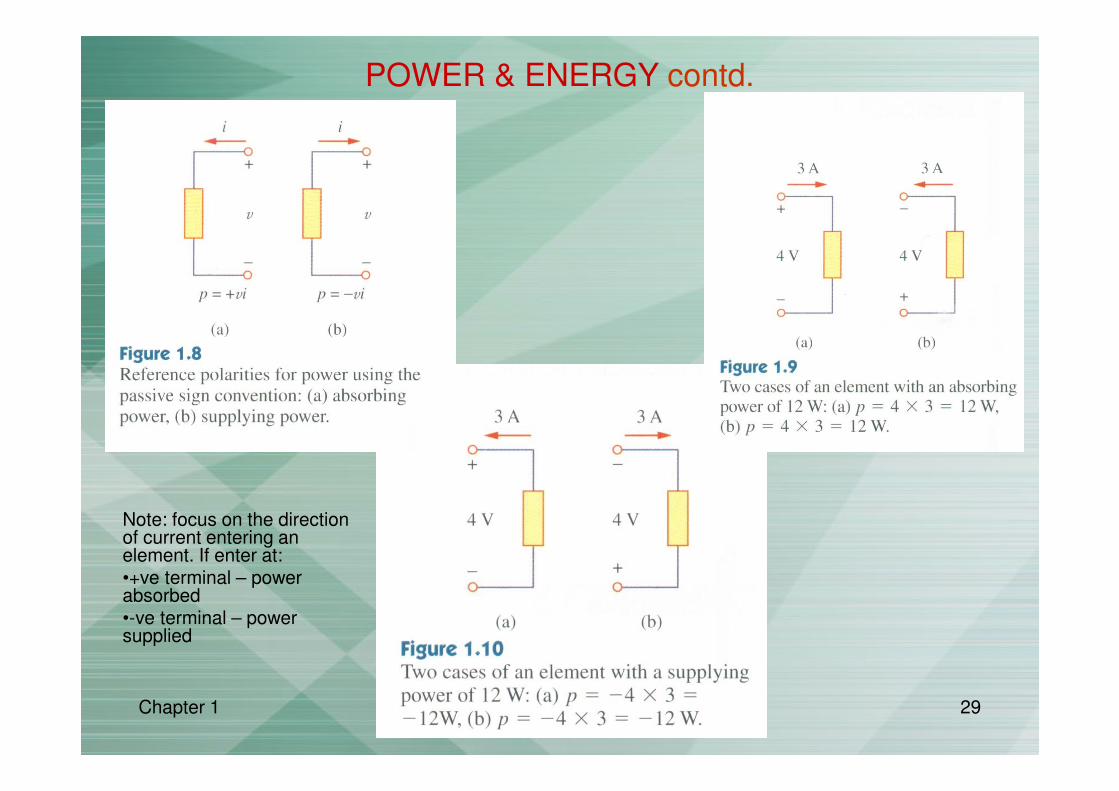
• In electric circuit, power can either be absorbed or
supplied by an element – the product of voltage across
the element and current through it.
• Positive power – power is absorb by the element.
• Negative power – power is supplied by the element.
• How to identify positive and negative power? Based on
the direction of current flow and voltage polarity.
P VI= +
POWER & ENERGY contd.
P VI= −
P VI=
Chapter 1 29
POWER & ENERGY contd.
Note: focus on the direction of current entering an element. If enter at:•+ve terminal – power absorbed •-ve terminal – power supplied

Chapter 1 30
• Law of conservation of energy – energy cannot be
created or destroyed, but can change its form.
• Therefore, the algebraic sum of power in a circuit, at any
instant of time, must be zero.
• The total power supplied to the circuit must equal to the
total power absorbed.
0P =∑
POWER & ENERGY contd.
This image cannot currently be displayed.
supplied absorbedP P=∑ ∑
Chapter 1 31
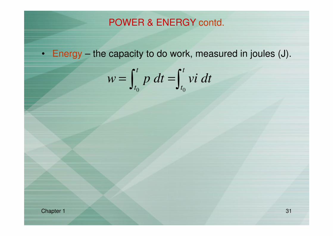
• Energy – the capacity to do work, measured in joules (J).
POWER & ENERGY contd.
0 0
t t
t tw p dt vi dt= =∫ ∫
Chapter 1 32
CIRCUIT ELEMENTS
• Element – basic building block of a circuit or electricalcomponents of an electrical circuit.
• Electric circuit – an interconnection of electricalelements.
• Circuit analysis – process of determining voltages across(or the currents through) the elements of the circuit.
• Two types of elements in electrical circuits:– Active elements
– Passive elements

Chapter 1 33
• Active elements – elements capable ofgenerating electrical energy i.e. voltage source& current source.
• Passive elements – elements not capable ofgenerating electrical energy i.e. resistor,capacitor and inductors.
• Voltage & current source deliver power to theelectrical circuit.
• Two kinds of sources:– Independent sources.
– Dependent sources.
CIRCUIT ELEMENTS contd.

Chapter 1 34
• Ideal independent source – an activeelements that provides a specified voltageor current that is completely independentof other circuit elements.
CIRCUIT ELEMENTS contd.
Chapter 1 35
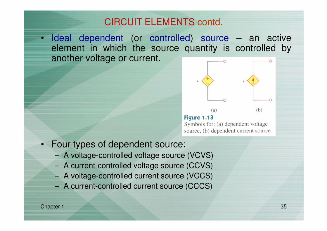
• Ideal dependent (or controlled) source – an activeelement in which the source quantity is controlled byanother voltage or current.
• Four types of dependent source:– A voltage-controlled voltage source (VCVS)
– A current-controlled voltage source (CCVS)
– A voltage-controlled current source (VCCS)
– A current-controlled current source (CCCS)
CIRCUIT ELEMENTS contd.

Chapter 1 36
• Consider the following:
– The CCVS is depends on i.
– Value = 10i V
CIRCUIT ELEMENTS contd.

Chapter 1 37
SYSTEMS OF UNITS
• Basic SI (International System of Units) units:
Quantity Unit Symbol
Charge (q) coulomb C
Energy (E) joule J
Power (P) watt W
Voltage (V) volt V
Current (I) ampere A
Resistance (R) ohm Ω
Induction (L) Henry H
Capacitance (C) farad F
Chapter 1 38
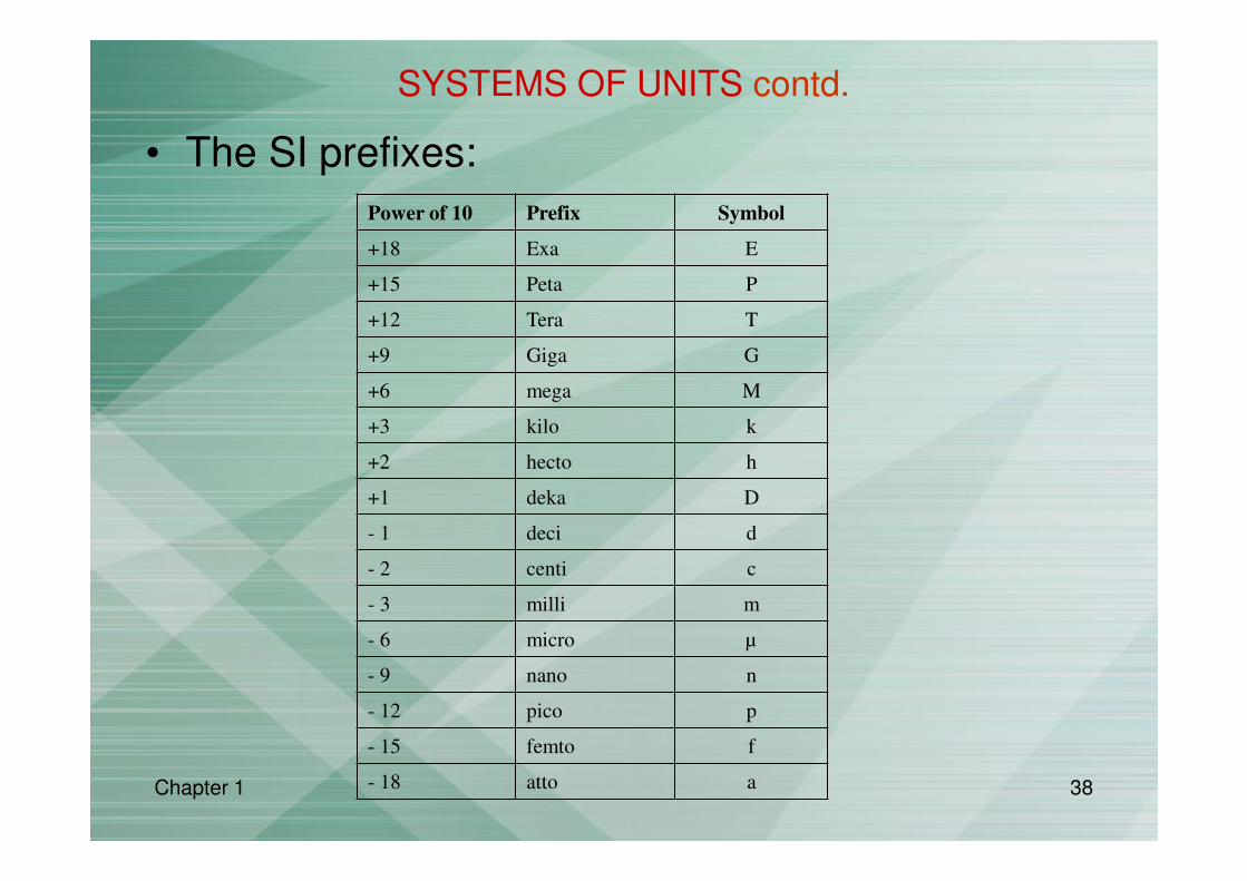
• The SI prefixes:
Power of 10 Prefix Symbol
+18 Exa E
+15 Peta P
+12 Tera T
+9 Giga G
+6 mega M
+3 kilo k
+2 hecto h
+1 deka D
- 1 deci d
- 2 centi c
- 3 milli m
- 6 micro µ
- 9 nano n
- 12 pico p
- 15 femto f
- 18 atto a
SYSTEMS OF UNITS contd.

Chapter 1 39
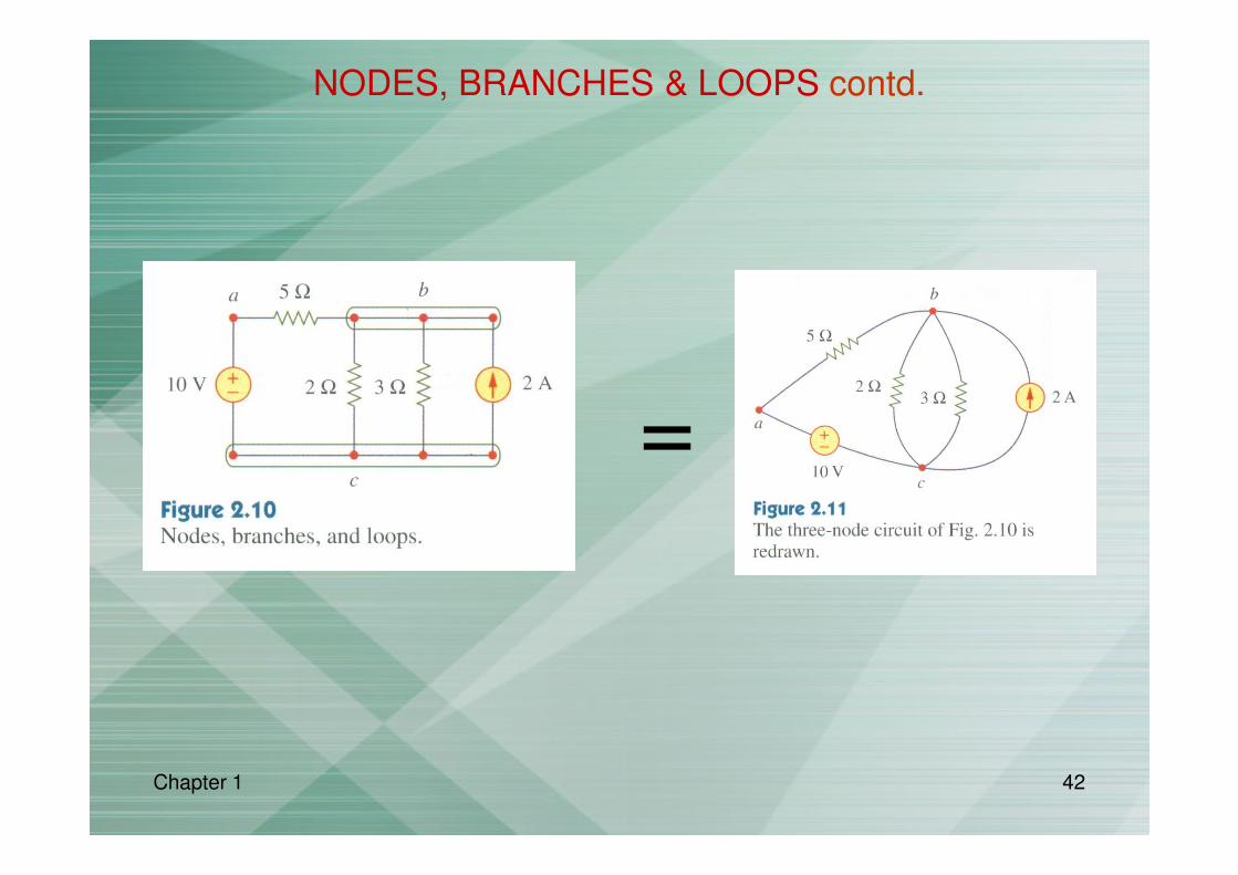
There are 5 branches.
NODES, BRANCHES & LOOPS
• Branch – represents a single elements such as voltage
source or a resistor.
Number of branches?Named the branches?
10 V voltage source, 2 A current source and three resistors
5 branches. There are the 10 V voltage source, 2 A current source and three resistors.

Chapter 1 40
• Node – a point of connection between two or more
branches.
NODES, BRANCHES & LOOPS contd.

Chapter 1 41
• Indicated by a dot.
• A node where the point of connection between three or
more branches is called essential node.
NODES, BRANCHES & LOOPS contd.
Chapter 1 42
=
NODES, BRANCHES & LOOPS contd.

Chapter 1 43
• Loop – any closed path in a circuit.
• A loop is a closed path formed by starting at a node,
passing through a set of nodes and returning to the
starting node without passing through any node more
than once.
NODES, BRANCHES & LOOPS contd.
Chapter 1 44
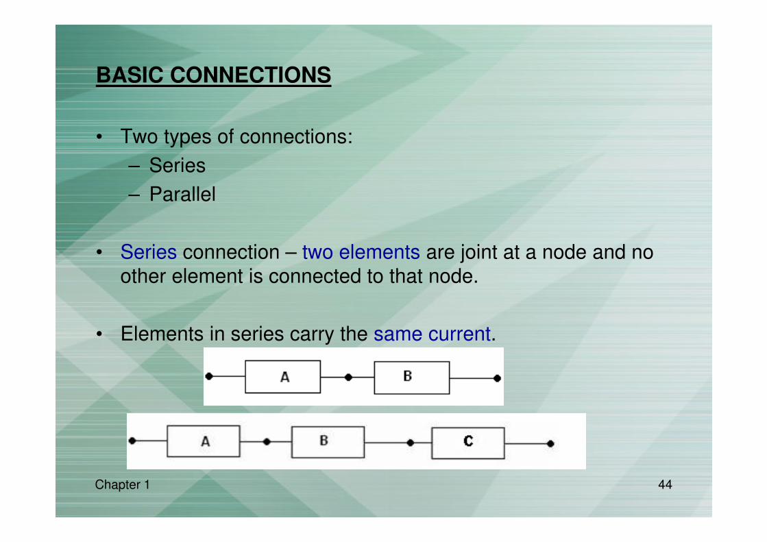
BASIC CONNECTIONS
• Two types of connections:
– Series
– Parallel
• Series connection – two elements are joint at a node and no
other element is connected to that node.
• Elements in series carry the same current.

Chapter 1 45
The series connection are:
• A & B
• D, E & F
BASIC CONNECTIONS contd.

Chapter 1 46
• Parallel – elements that are connected to the
same pair of terminals.
• Elements in parallel have the same voltage
across them
BASIC CONNECTIONS contd.

Chapter 1 47
Parallel connections:
• C &D
• G, H & J
Series connection – A & B
BASIC CONNECTIONS contd.
Chapter 1 48
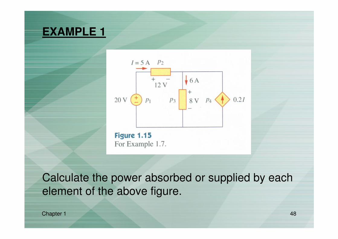
EXAMPLE 1
Calculate the power absorbed or supplied by each
element of the above figure.

Chapter 1 49
• p1 = 20(5) = 100 W– Since the current leaves the positive terminal thus,
p1 = -100 W
• p2 = 12(5) = 60 W
– The current enters the positive terminal
• p3 = 8(6) = 48 W– The current enters the positive terminal
• p4 = 8(0.2I) = 8(0.2 x 5) = 8 W– Since the current leaves the positive terminal thus,
p4 = -8W
EXAMPLE 1 contd.

Chapter 1 50
• Algebraic sum of power in the circuit
p1 + p2 + p3 + p4 = -100 + 60 + 48 – 8 = 0
EXAMPLE 1 contd.

Chapter 1 51
EXAMPLE 2
Calculate the power absorbed or supplied by each
element of the above figure.

Chapter 1 52
• p1 = -40 W
• p2 = 16 W
• p3 = 9 W
• p4 = 15 W
• p1 + p2 + p3 + p4 = -40 + 16 + 9 – 15 = 0
EXAMPLE 2 contd.

Chapter 1 53
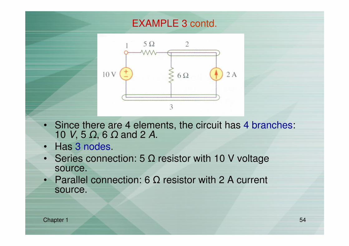
EXAMPLE 3
Determine the number of branches and nodes. Identify which elements are in series and parallel.
Chapter 1 54
• Since there are 4 elements, the circuit has 4 branches: 10 V, 5 Ω, 6 Ω and 2 A.
• Has 3 nodes.
• Series connection: 5 Ω resistor with 10 V voltage source.
• Parallel connection: 6 Ω resistor with 2 A current source.
EXAMPLE 3 contd.
Chapter 1 55
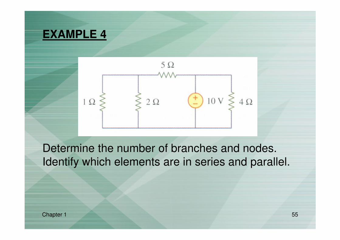
EXAMPLE 4
Determine the number of branches and nodes.
Identify which elements are in series and parallel.

Chapter 1 56
• Since there are 5 elements, the circuit has 5 branches
• Has 3 nodes.
• Parallel connection: – 1 Ω & 2 Ω resistors.
– 4 Ω resistor with 10 V source.
EXAMPLE 4 contd.
Chapter 1 57
RECALL
• Dc – current that remains constant with time.
• Dc voltage – voltage that remains constant with time.
• Ac – current that varies sinusoidally with time.
• Ac voltage – voltage that varies sinusoidally with time.