chapter 1 introduction€¦ · magneto ignition system. 7 3. what type of governing used in s.i...
TRANSCRIPT

GTU PAPER ANALYSIS
Fluid Mechanics (2141906) Department of Mechanical Engineering Darshan Institute of Engineering & Technology
Chapter 1 – Introduction
Sr No.
Question
Ma
y-1
6
Oct
-16
Ma
y-1
7
No
v-1
7
Ma
y-1
8
No
v-1
8
1. Define: 1. Compression ratio 2. Cut-off ratio 3. IC Engine 4. Mean effective pressure 5. Indicate Power 6. Brake Power 7. Friction Power 8. Mechanical Efficiency 9. Air standard efficiency 10. Thermal efficiency 11. Relative efficiency 12. Volumetric efficiency 13. Volumetric efficiency 14. Specific fuel consumption
1 3 3 4
2. What is I.C. Engine? Compare I.C. Engines with E.C. Engines. 3 3. Explain with the help of neat sketch, the working of a 2-stroke petrol engine. 4 4 4. Compare S.I. engines with C.I engines. 3 3 5. Explain with the help of neat sketch, the working of a 4-stroke Diesel engine. 4 6. Mention the assumptions made in air-standard cycle analysis of I.C. engine. 4

GTU PAPER ANALYSIS
Fluid Mechanics (2141906) Department of Mechanical Engineering Darshan Institute of Engineering & Technology
Chapter 2 – Fuel air and Actual air cycles
Sr No.
Question
Ma
y-1
6
Oct
-16
Ma
y-1
7
No
v-1
7
Ma
y-1
8
No
v-1
8
1. Explain with neat sketch valve timing diagram for Diesel engine. Also explain deviation of an actual cycle from an ideal cycle.
7 6 7 7
2. Explain different losses as applied to I.C. engines. OR
Explain pumping loss and rubbing friction loss as applied to I.C. Engines?
7 7 7 4
3. What is fuel air cycle? Explain the phenomenon of dissociation. OR What is the effect of carbon monoxide on dissociation? Explain the effect of dissociation on maximum temperature and brake power with the help of suitable diagram.
7 7 7
4. Draw & explain valve timing diagram of 4-stroke petrol engine. 7 3 5. What do you mean by air standard cycle and fuel air cycle? List assumptions for
air standard cycle and fuel air cycle. 7 3
6. Explain the variation in specific heat and loss due to it in an Otto cycle with the help of P-V diagram.
OR Explain with P-V diagram the effect of variable specific heat on Otto, Diesel and Dual cycle.
7
7. Define Air standard, Fuel air and Actual cycle. 3 8. Define Rich, Lean and Stoichiometric A:F mixture. 3
Examples 1. Calculate the percentage change in efficiency of air standard Otto cycle having a
compression ratio of 7 for the following cases: (1) The specific heat at constant volume increase by 2% (2) The specific heat at constant pressure increased by 2% Assuming γ to be invariant.
7
2. A diesel engine working on diesel cycle uses compression ratio of 18. The cut off is 6% of stroke at a particular load. The specific heat at constant volume
7
GTU PAPER ANALYSIS
Fluid Mechanics (2141906) Department of Mechanical Engineering Darshan Institute of Engineering & Technology
increases by 1.2%. Find the percentage change in the air-standard efficiency of the cycle. Take Cv = 0.72 KJ/kg K and R = 287 J/kg K as an average values.

GTU PAPER ANALYSIS
Fluid Mechanics (2141906) Department of Mechanical Engineering Darshan Institute of Engineering & Technology
Chapter 3 – Combustion
Sr No.
Question
Ma
y-1
6
Oct
-16
Ma
y-1
7
No
v-1
7
Ma
y-1
8
No
v-1
8
1. Explain construction and working of Junker’s gas calorimeter with neat sketch. 7 7 7 7 2. Discuss the significance of distillation curve. 7 3. Define and Explain calorific value of fuel used in I.C.engines. 3 4. Explain working and construction of bomb calorimeter. 7 5. Explain following terms with respect to combustion in SI engine.
(1) Enthalpy of formation, (2) Adiabatic flame temperature, (3) Lean mixture and Rich mixture.
3
6. What is stoichiometric air fuel ratio? Find stoichiometric air fuel ratio for Iso-octane.
7
GTU PAPER ANALYSIS
Fluid Mechanics (2141906) Department of Mechanical Engineering Darshan Institute of Engineering & Technology
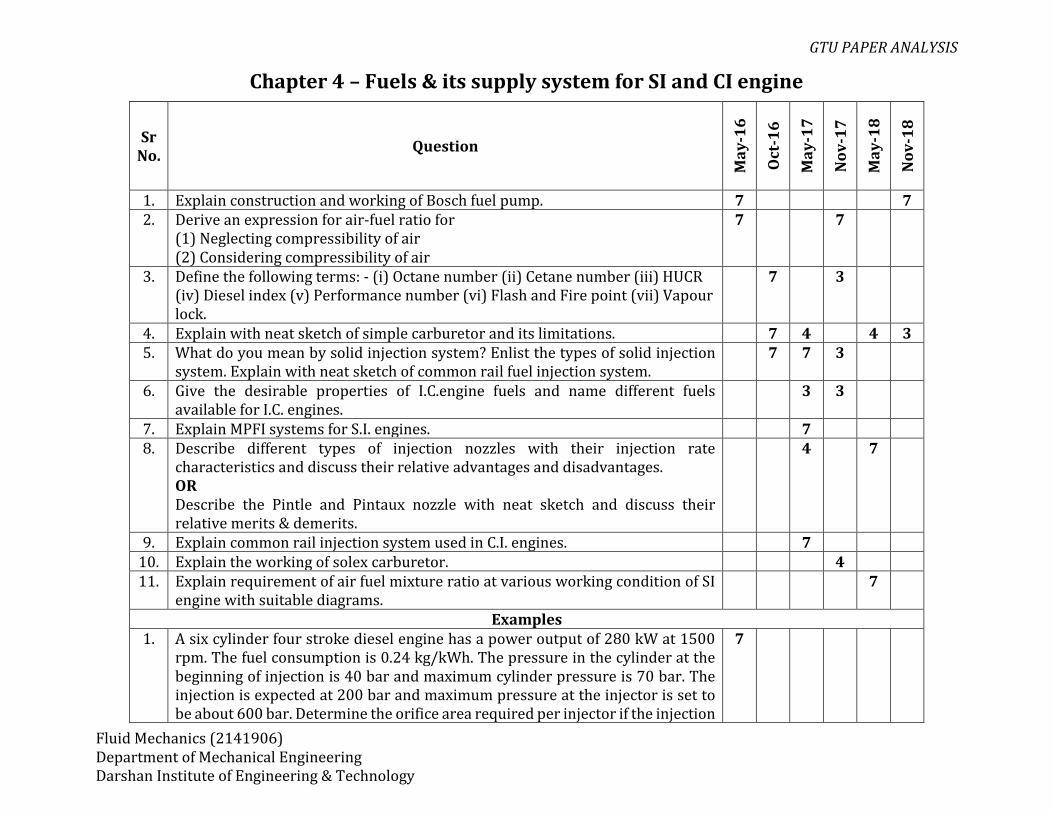
Chapter 4 – Fuels & its supply system for SI and CI engine
Sr No.
Question
Ma
y-1
6
Oct
-16
Ma
y-1
7
No
v-1
7
Ma
y-1
8
No
v-1
8
1. Explain construction and working of Bosch fuel pump. 7 7 2. Derive an expression for air-fuel ratio for
(1) Neglecting compressibility of air (2) Considering compressibility of air
7 7
3. Define the following terms: - (i) Octane number (ii) Cetane number (iii) HUCR (iv) Diesel index (v) Performance number (vi) Flash and Fire point (vii) Vapour lock.
7 3
4. Explain with neat sketch of simple carburetor and its limitations. 7 4 4 3 5. What do you mean by solid injection system? Enlist the types of solid injection
system. Explain with neat sketch of common rail fuel injection system. 7 7 3
6. Give the desirable properties of I.C.engine fuels and name different fuels available for I.C. engines.
3 3
7. Explain MPFI systems for S.I. engines. 7 8. Describe different types of injection nozzles with their injection rate
characteristics and discuss their relative advantages and disadvantages. OR Describe the Pintle and Pintaux nozzle with neat sketch and discuss their relative merits & demerits.
4 7
9. Explain common rail injection system used in C.I. engines. 7 10. Explain the working of solex carburetor. 4 11. Explain requirement of air fuel mixture ratio at various working condition of SI
engine with suitable diagrams. 7
Examples 1. A six cylinder four stroke diesel engine has a power output of 280 kW at 1500
rpm. The fuel consumption is 0.24 kg/kWh. The pressure in the cylinder at the beginning of injection is 40 bar and maximum cylinder pressure is 70 bar. The injection is expected at 200 bar and maximum pressure at the injector is set to be about 600 bar. Determine the orifice area required per injector if the injection
7
GTU PAPER ANALYSIS
Fluid Mechanics (2141906) Department of Mechanical Engineering Darshan Institute of Engineering & Technology
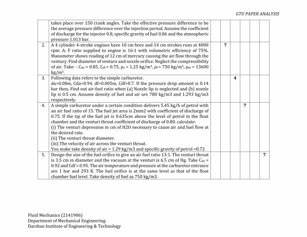
takes place over 150 crank angles. Take the effective pressure difference to be the average pressure difference over the injection period. Assume the coefficient of discharge for the injector 0.8, specific gravity of fuel 0.86 and the atmospheric pressure 1.013 bar.
2. A 4 cylinder 4-stroke engines have 10 cm bore and 14 cm strokes runs at 4000 rpm. A: F ratio supplied to engine is 16:1 with volumetric efficiency of 75%. Manometer shows reading of 12 cm of mercury causing the air flow through the ventury. Find diameter of venture and nozzle orifice. Neglect the compressibility of air. Take: - Cda = 0.85, Cdf = 0.75, ρa = 1.25 kg/m3, ρf = 750 kg/m3, ρm = 13600 kg/m3.
7
3. Following data refers to the simple carburetor. da=0.08m, Cda=0.94, df=0.005m, Cdf=0.7. If the pressure drop amount is 0.14 bar then, Find out air-fuel ratio when (a) Nozzle lip is neglected and (b) nozzle lip is 0.5 cm. Assume density of fuel and air are 780 kg/m3 and 1.293 kg/m3 respectively.
4
4. A simple carburetor under a certain condition delivers 5.45 kg/h of petrol with an air fuel ratio of 15. The fuel jet area is 2mm2 with coefficient of discharge of 0.75. If the tip of the fuel jet is 0.635cm above the level of petrol in the float chamber and the venturi throat coefficient of discharge of 0.80. calculate: (i) The venturi depression in cm of H2O necessary to cause air and fuel flow at the desired rate. (ii) The venturi throat diameter. (iii) The velocity of air across the venturi throat. You make take density of air = 1.29 kg/m3 and specific gravity of petrol =0.72
7
5. Design the size of the fuel orifice to give an air fuel ratio 13:1. The venturi throat is 3.5 cm in diameter and the vacuum at the venturi is 6.5 cm of Hg. Take Cda = 0.92 and Cdf = 0.95. The air temperature and pressure at the carburetor entrance are 1 bar and 293 K. The fuel orifice is at the same level as that of the float chamber fuel level. Take density of fuel as 750 kg/m3.
7
GTU PAPER ANALYSIS
Fluid Mechanics (2141906) Department of Mechanical Engineering Darshan Institute of Engineering & Technology
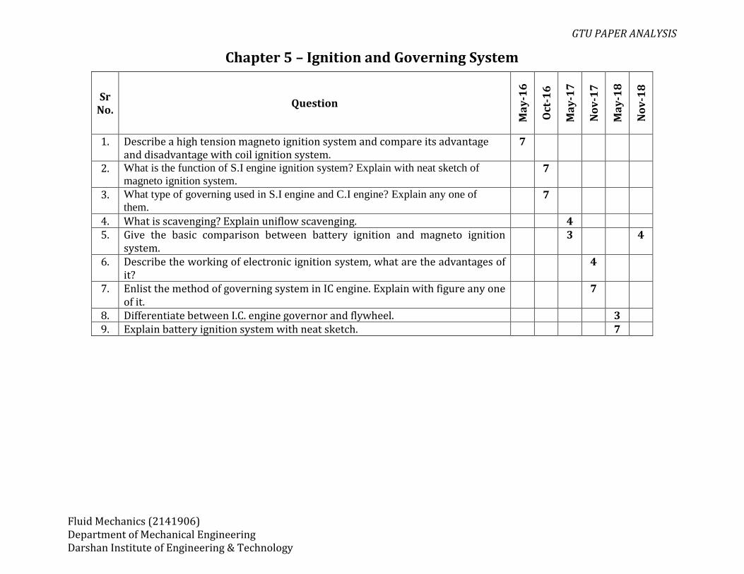
Chapter 5 – Ignition and Governing System
Sr No.
Question
Ma
y-1
6
Oct
-16
Ma
y-1
7
No
v-1
7
Ma
y-1
8
No
v-1
8
1. Describe a high tension magneto ignition system and compare its advantage and disadvantage with coil ignition system.
7
2. What is the function of S.I engine ignition system? Explain with neat sketch of
magneto ignition system. 7
3. What type of governing used in S.I engine and C.I engine? Explain any one of
them. 7
4. What is scavenging? Explain uniflow scavenging. 4 5. Give the basic comparison between battery ignition and magneto ignition
system. 3 4
6. Describe the working of electronic ignition system, what are the advantages of it?
4
7. Enlist the method of governing system in IC engine. Explain with figure any one of it.
7
8. Differentiate between I.C. engine governor and flywheel. 3 9. Explain battery ignition system with neat sketch. 7
GTU PAPER ANALYSIS
Fluid Mechanics (2141906) Department of Mechanical Engineering Darshan Institute of Engineering & Technology
Chapter 6 – Supercharging
Sr No.
Question
Ma
y-1
6
Oct
-16
Ma
y-1
7
No
v-1
7
Ma
y-1
8
No
v-1
8
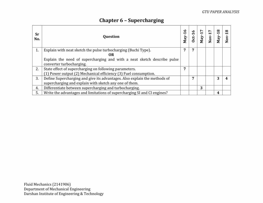
1. Explain with neat sketch the pulse turbocharging (Buchi Type). OR
Explain the need of supercharging and with a neat sketch describe pulse converter turbocharging.
7 7
2. State effect of supercharging on following parameters. (1) Power output (2) Mechanical efficiency (3) Fuel consumption.
7
3. Define Supercharging and give its advantages. Also explain the methods of supercharging and explain with sketch any one of them.
7 3 4
4. Differentiate between supercharging and turbocharging. 3 5. Write the advantages and limitations of supercharging SI and CI engines? 4
GTU PAPER ANALYSIS
Fluid Mechanics (2141906) Department of Mechanical Engineering Darshan Institute of Engineering & Technology
Chapter 7 – Combustion in SI & CI engines
Sr No.
Question
Ma
y-1
6
Oct
-16
Ma
y-1
7
No
v-1
7
Ma
y-1
8
No
v-1
8
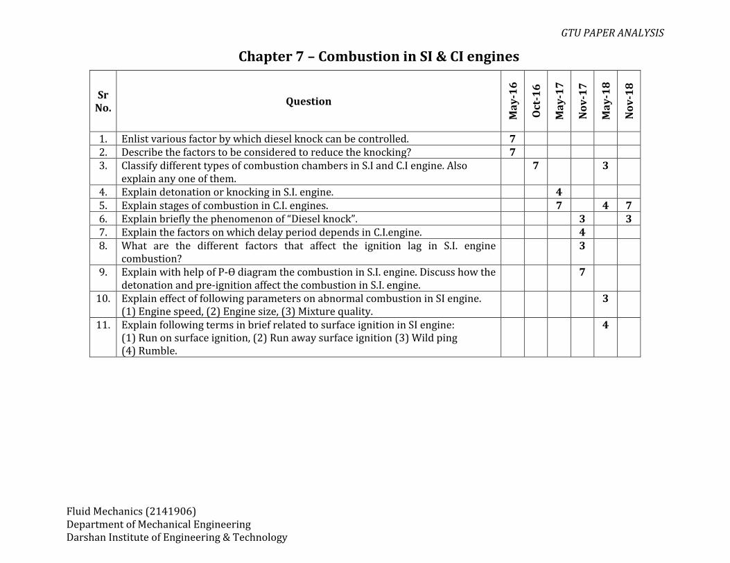
1. Enlist various factor by which diesel knock can be controlled. 7 2. Describe the factors to be considered to reduce the knocking? 7 3. Classify different types of combustion chambers in S.I and C.I engine. Also
explain any one of them. 7 3
4. Explain detonation or knocking in S.I. engine. 4 5. Explain stages of combustion in C.I. engines. 7 4 7 6. Explain briefly the phenomenon of “Diesel knock”. 3 3 7. Explain the factors on which delay period depends in C.I.engine. 4 8. What are the different factors that affect the ignition lag in S.I. engine
combustion? 3
9. Explain with help of P-ϴ diagram the combustion in S.I. engine. Discuss how the detonation and pre-ignition affect the combustion in S.I. engine.
7
10. Explain effect of following parameters on abnormal combustion in SI engine. (1) Engine speed, (2) Engine size, (3) Mixture quality.
3
11. Explain following terms in brief related to surface ignition in SI engine: (1) Run on surface ignition, (2) Run away surface ignition (3) Wild ping (4) Rumble.
4
GTU PAPER ANALYSIS
Fluid Mechanics (2141906) Department of Mechanical Engineering Darshan Institute of Engineering & Technology
Chapter 8 – Engine Lubrication & Cooling
Sr No.
Question
Ma
y-1
6
Oct
-16
Ma
y-1
7
No
v-1
7
Ma
y-1
8
No
v-1
8
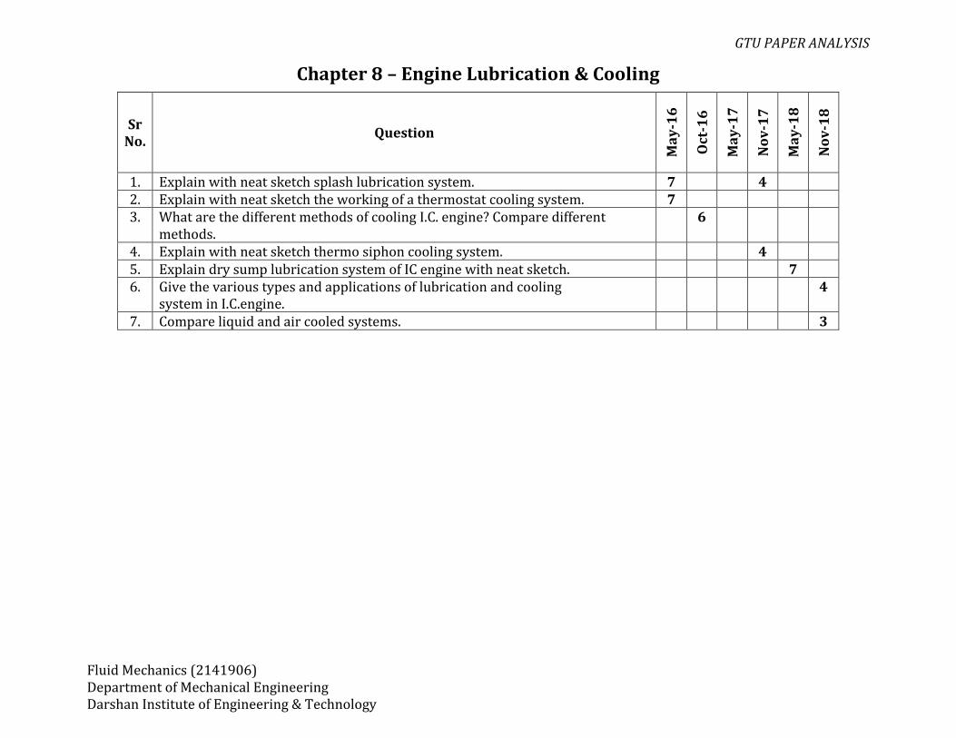
1. Explain with neat sketch splash lubrication system. 7 4 2. Explain with neat sketch the working of a thermostat cooling system. 7 3. What are the different methods of cooling I.C. engine? Compare different
methods. 6
4. Explain with neat sketch thermo siphon cooling system. 4 5. Explain dry sump lubrication system of IC engine with neat sketch. 7 6. Give the various types and applications of lubrication and cooling
system in I.C.engine. 4
7. Compare liquid and air cooled systems. 3

GTU PAPER ANALYSIS
Fluid Mechanics (2141906) Department of Mechanical Engineering Darshan Institute of Engineering & Technology
Chapter 9 – Measurement & Testing of IC engines
Sr No.
Question
Ma
y-1
6
Oct
-16
Ma
y-1
7
No
v-1
7
Ma
y-1
8
No
v-1
8
Theory 1. Discuss a “Heat balance sheet” in 350 words.
OR Explain and draw up the heat balance sheet with necessary equations to represent the heat distribution on minute and percentage basis.
7 7
2. Describe the “Morse test”. Write the assumptions made and limitation of this test.
7 3 4
Examples 1. A two stroke diesel engine was motored when energy meter reading was 1.5 kW.
Then the test on the engine was carried out for 1 hour and following observations were recorded:- Brake torque = 120 Nm, RPM = 600, Fuel used = 2.5 kg, C.V of fuel = 40.3 MJ/kg, Cooling water used = 818 kg, Rise in cooling water temperature = 100 C, Cpw = 4.2 KJ/kg K, Exhaust gas temperature = 3450 °C, Room temperature = 250 °C, A:F used = 32:1, Cpg = 1.05 KJ/kg K. Draw heat balance sheet indicating units in KJ/min basis and also on percentage basis.
7
2. A 4-stroke 4- cylinder petrol engine develops 30 kw power at 1500 rpm. The average torque produces when each cylinder cut off is 130 Nm. The fuel used has calorific value 43.5 MJ/kg and bsfc is 0.40 kg/kwhr. Calculate 1. Mechanical efficiency 2. Indicated thermal efficiency and 3. Brake thermal efficiency.
7
3. In a test of a 4-cylinder, 4-stroke engine 75mm bore and 100mm stroke, the following results were obtained at full throttle at a particular constant speed and with fixed setting of fuel supply of 6 kg/hr. B.P. with all cylinder working =15.6kW B.P. with cylinder no. 1 cut-out =11.1kW B.P. with cylinder no. 2 cut-out =11.03kW B.P. with cylinder no. 3 cut-out =10.88kW B.P. with cylinder no. 4 cut-out =10.66kW
7
GTU PAPER ANALYSIS
Fluid Mechanics (2141906) Department of Mechanical Engineering Darshan Institute of Engineering & Technology
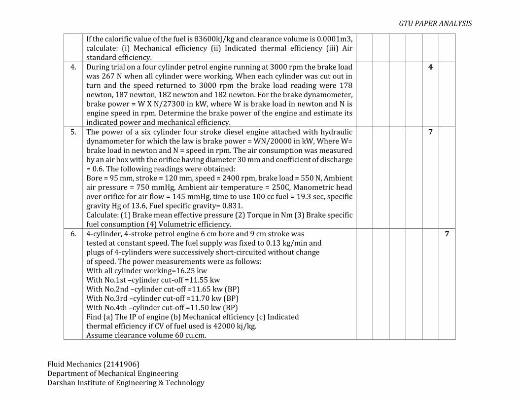
If the calorific value of the fuel is 83600kJ/kg and clearance volume is 0.0001m3, calculate: (i) Mechanical efficiency (ii) Indicated thermal efficiency (iii) Air standard efficiency.
4. During trial on a four cylinder petrol engine running at 3000 rpm the brake load was 267 N when all cylinder were working. When each cylinder was cut out in turn and the speed returned to 3000 rpm the brake load reading were 178 newton, 187 newton, 182 newton and 182 newton. For the brake dynamometer, brake power = W X N/27300 in kW, where W is brake load in newton and N is engine speed in rpm. Determine the brake power of the engine and estimate its indicated power and mechanical efficiency.
4
5. The power of a six cylinder four stroke diesel engine attached with hydraulic dynamometer for which the law is brake power = WN/20000 in kW, Where W= brake load in newton and N = speed in rpm. The air consumption was measured by an air box with the orifice having diameter 30 mm and coefficient of discharge = 0.6. The following readings were obtained: Bore = 95 mm, stroke = 120 mm, speed = 2400 rpm, brake load = 550 N, Ambient air pressure = 750 mmHg, Ambient air temperature = 250C, Manometric head over orifice for air flow = 145 mmHg, time to use 100 cc fuel = 19.3 sec, specific gravity Hg of 13.6, Fuel specific gravity= 0.831. Calculate: (1) Brake mean effective pressure (2) Torque in Nm (3) Brake specific fuel consumption (4) Volumetric efficiency.
7
6. 4-cylinder, 4-stroke petrol engine 6 cm bore and 9 cm stroke was tested at constant speed. The fuel supply was fixed to 0.13 kg/min and plugs of 4-cylinders were successively short-circuited without change of speed. The power measurements were as follows: With all cylinder working=16.25 kw With No.1st –cylinder cut-off =11.55 kw With No.2nd –cylinder cut-off =11.65 kw (BP) With No.3rd –cylinder cut-off =11.70 kw (BP) With No.4th –cylinder cut-off =11.50 kw (BP) Find (a) The IP of engine (b) Mechanical efficiency (c) Indicated thermal efficiency if CV of fuel used is 42000 kj/kg. Assume clearance volume 60 cu.cm.
7

GTU PAPER ANALYSIS
Fluid Mechanics (2141906) Department of Mechanical Engineering Darshan Institute of Engineering & Technology

GTU PAPER ANALYSIS
Fluid Mechanics (2141906) Department of Mechanical Engineering Darshan Institute of Engineering & Technology
Chapter 10 – Engine Emission & Their Control
Sr No.
Question
Ma
y-1
6
Oct
-16
Ma
y-1
7
No
v-1
7
Ma
y-1
8
No
v-1
8
1. Tell Bharat Stages of emission norms in brief for cars and two wheelers. 7 2. Explain briefly Emission norms (Euro and Bharat stage). 3 3 3. Explain briefly exhaust gas recirculation system- EGR for I.C. engines. 4 4. Describe with neat sketch the ELCD to control evaporative emission from SI
engine. 4
5. Write a short note on air pollution due to IC engines. Enlist major pollutants from gasoline & diesel engines.
3 4
6. Write a short note on three way catalytic convertor with neat sketch. 4

GTU PAPER ANALYSIS
Fluid Mechanics (2141906) Department of Mechanical Engineering Darshan Institute of Engineering & Technology
Chapter 11 – Diesel Power Plant
Sr No.
Question
Ma
y-1
6
Oct
-16
Ma
y-1
7
No
v-1
7
Ma
y-1
8
No
v-1
8
1. Discuss the application of diesel plants and its advantages and disadvantages. 4 4 4 2. Draw a layout of diesel engine power plant. 3