chapter 1 temporary erosion control management …
TRANSCRIPT
01/14 Chapter 1 Temporary Erosion Control Management
CHAPTER 1 TEMPORARY EROSION CONTROL MANAGEMENT
1.1 Introduction The requirement that erosion control be initiated on all exposed soil surfaces within a given timeframe is an integral compliance component on virtually all construction and maintenance projects. Temporary erosion control best management practices (BMPs) are short-term measures that should always be considered during a period where areas are disturbed due to construction or maintenance activities. When an emergency such as a slide or flood occurs, a temporary BMP should facilitate erosion protection, or at least be compatible with, long-term or permanent BMPs.
A temporary erosion control BMP is normally used for 1—6 months, or until a more permanent BMP is put into place. Temporary BMPs are used to minimize or eliminate erosion and are designed and installed to keep as much sediment on-site as possible.
The proper installation and maintenance of temporary BMPs allow for cleaner water runoff into the receiving waters such as streams, rivers, and lakes. Erosion control is the primary and initial consideration in a construction soil-disturbing project. If erosion control BMPs are installed and maintained correctly, there should be minimal sediment control needed on a project.
1.2 Erosion Control Goals Erosion control goals can be separated into three categories.
1. Perimeter Controls a. Ensure that no sediment or sediment laden water, or only a minimal amount,
enters onto or leaves the project area.
b. Treat or filter sediment-laden discharge waters as many times as required to meet Idaho water quality standards before leaving the project area.
2. Controls within the Project a. Maintain erosion control on cut-and-fill slopes and in ditches or channels.
b. Prevent erosion on disturbed areas.
c. Divert stormwater away from the project, and especially disturbed areas.
d. Maintain stockpiles such that run-on, runoff, and wind erosion are minimized.
e. Protect all Waters of the United States (ponds, streams, wetlands, etc.), and ensure that discharges meet applicable Idaho water quality standards.
3. Final Product a. Coordinate all temporary erosion controls to facilitate permanent measures.
b. Remove and properly dispose of all controls that were installed and maintained during construction, accept those that are intended for long-term use or those that are biodegradable.
01/14 Chapter 2 Temporary Erosion Control Management
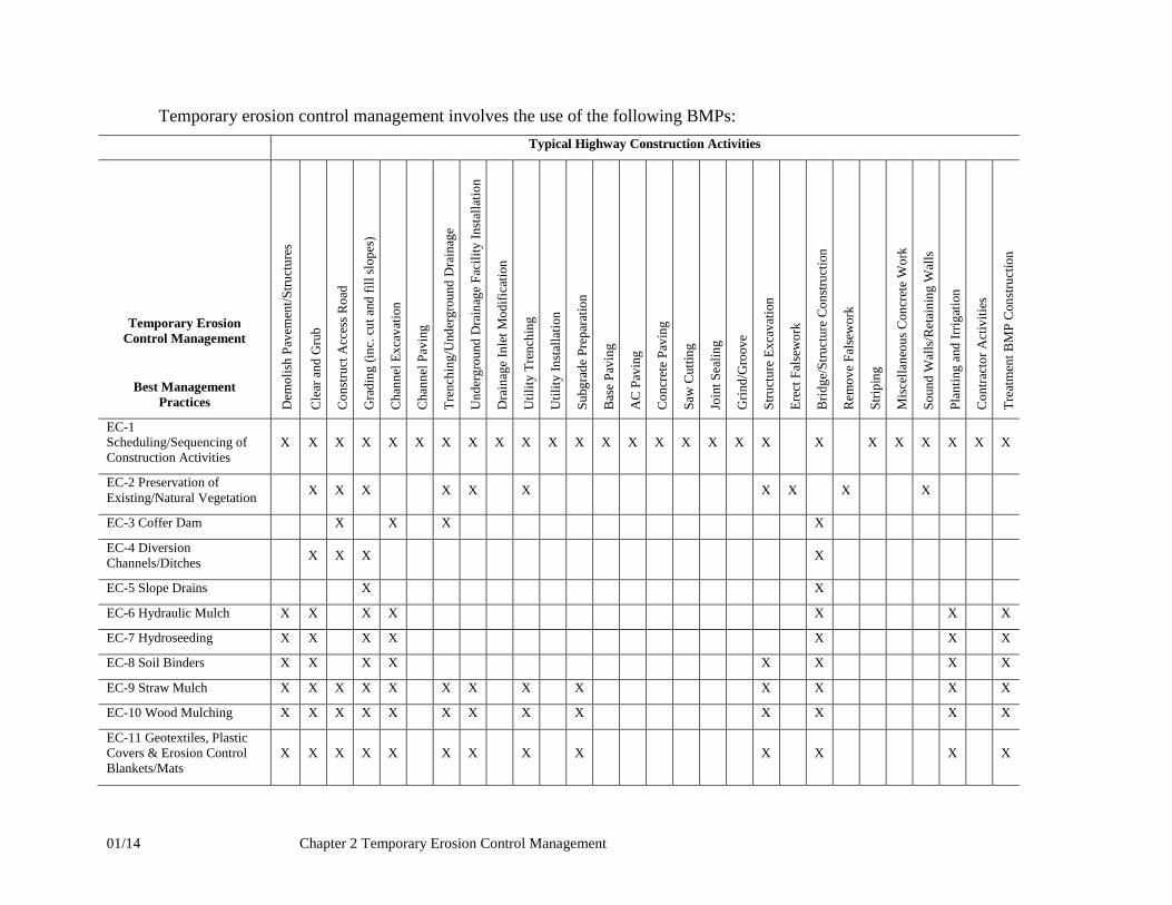
Temporary erosion control management involves the use of the following BMPs: Typical Highway Construction Activities
Temporary Erosion Control Management
Best Management Practices D
emol
ish
Pave
men
t/Stru
ctur
es
Cle
ar a
nd G
rub
Con
stru
ct A
cces
s Roa
d
Gra
ding
(inc
. cut
and
fill
slop
es)
Cha
nnel
Exc
avat
ion
Cha
nnel
Pav
ing
Tren
chin
g/U
nder
grou
nd D
rain
age
Und
ergr
ound
Dra
inag
e Fa
cilit
y In
stal
latio
n
Dra
inag
e In
let M
odifi
catio
n
Util
ity T
renc
hing
Util
ity In
stal
latio
n
Subg
rade
Pre
para
tion
Bas
e Pa
ving
AC
Pav
ing
Con
cret
e Pa
ving
Saw
Cut
ting
Join
t Sea
ling
Grin
d/G
roov
e
Stru
ctur
e Ex
cava
tion
Erec
t Fal
sew
ork
Brid
ge/S
truct
ure
Cons
truct
ion
Rem
ove
Fals
ewor
k
Strip
ing
Mis
cella
neou
s Con
cret
e W
ork
Soun
d W
alls
/Ret
aini
ng W
alls
Plan
ting
and
Irrig
atio
n
Con
tract
or A
ctiv
ities
Trea
tmen
t BM
P C
onst
ruct
ion
EC-1 Scheduling/Sequencing of Construction Activities
X X X X X X X X X X X X X X X X X X X X X X X X X X
EC-2 Preservation of Existing/Natural Vegetation X X X X X X X X X X
EC-3 Coffer Dam X X X X
EC-4 Diversion Channels/Ditches X X X X
EC-5 Slope Drains X X
EC-6 Hydraulic Mulch X X X X X X X
EC-7 Hydroseeding X X X X X X X
EC-8 Soil Binders X X X X X X X X
EC-9 Straw Mulch X X X X X X X X X X X X X
EC-10 Wood Mulching X X X X X X X X X X X X X
EC-11 Geotextiles, Plastic Covers & Erosion Control Blankets/Mats
X X X X X X X X X X X X X

01/14 Chapter 2 Temporary Erosion Control Management
Typical Highway Construction Activities
Temporary Erosion Control Management
Best Management Practices D
emol
ish
Pave
men
t/Stru
ctur
es
Cle
ar a
nd G
rub
Con
stru
ct A
cces
s Roa
d
Gra
ding
(inc
. cut
and
fill
slop
es)
Cha
nnel
Exc
avat
ion
Cha
nnel
Pav
ing
Tren
chin
g/U
nder
grou
nd D
rain
age
Und
ergr
ound
Dra
inag
e Fa
cilit
y In
stal
latio
n
Dra
inag
e In
let M
odifi
catio
n
Util
ity T
renc
hing
Util
ity In
stal
latio
n
Subg
rade
Pre
para
tion
Bas
e Pa
ving
AC
Pav
ing
Con
cret
e Pa
ving
Saw
Cut
ting
Join
t Sea
ling
Grin
d/G
roov
e
Stru
ctur
e Ex
cava
tion
Erec
t Fal
sew
ork
Brid
ge/S
truct
ure
Cons
truct
ion
Rem
ove
Fals
ewor
k
Strip
ing
Mis
cella
neou
s Con
cret
e W
ork
Soun
d W
alls
/Ret
aini
ng W
alls
Plan
ting
and
Irrig
atio
n
Con
tract
or A
ctiv
ities
Trea
tmen
t BM
P C
onst
ruct
ion
EC-12 Vegetation/Seeding X X X X
EC-13 Dust Control X X X X X X X X X X X X X X X X X
EC-14 Wind Erosion Control X X X X X X X X X X X X
EC-15 Snow Management X X

Best Management Practices Manual EC-1 Scheduling/Sequencing of Construction Activities
01/14 Chapter 1 Temporary Erosion Control Management
EC-1 SCHEDULING/SEQUENCING OF CONSTRUCTION ACTIVITIES Refer to: ITD Standard Specifications, Sections 108.03 and 212.03.
Definition and Purpose
• A critical factor in reducing erosion and subsequent sedimentation on construction projects is scheduling or planning the sequence of work at appropriate times or seasons. Another important factor is minimizing the total amount of disturbed soil exposed to erosion at any time. Large areas of disturbance could lead to additional water quality monitoring compliance requirements on your project.
• Proper scheduling of construction during periods when the potential for erosion is low and the effectiveness of erosion control measures is high will greatly reduce sediment loads due to runoff. The amounts of disturbed ground exposed at any one time before erosion control measures are put in place will always influence the amount of erosion and sediment loss.
Appropriate Applications Scheduling or sequencing is especially relevant to:
• Projects where ground is disturbed to facilitate construction.
• Large projects where work activities can be planned to coincide with periods of low erosion potential.
• Projects where an NPDES permit requires the minimization of exposed soil.
Limitations
• Contractor work scheduling may not coincide with the schedule that was anticipated during the design of the project or current weather conditions.
• Seasonal limitations are not always possible to incorporate, due to bidding, letting, timing, and administration of contracts.
BMP Objectives
Perimeter Control
Slope Protection
Borrow and Stockpiles
Drainage Areas
Sediment Trapping
Stream Protection
Temporary Stabilizing
Permanent Stabilizing
Best Management Practices Manual EC-1 Scheduling/Sequencing of Construction Activities
01/14 Chapter 1 Temporary Erosion Control Management
• Certain environmental permits and their requirements may contain restrictions on scheduling or sequencing of certain work activities and the maximum allowable exposure of surface area.
Design Parameters
• SWPPP requirements shall be included to clarify allowable parameters. Erosion potential and maximum area that can be exposed at any time should be evaluated based on specified criterion cited in the NPDES Permit and contract specifications, and consideration of terrain, soil type, season of work, and current and forecasted weather conditions.
• Required erosion control measures and disturbed surface area limitations should be specified in the work scheduling, SWPPP, and project plans and specifications.
• Whenever possible, construction work should be scheduled during seasonal low runoff periods and under favorable soil moisture conditions.
• Installation of erosion control measures should be scheduled or timed in stages to coincide with construction sequencing and as required by the NPDES permit.
Construction Guidelines
• The Contractor shall develop a schedule and work plan indicating sequence of activities. The Contractor shall schedule construction activities when the potential for erosion is low and allow time for installation of erosion control measures as the work phasing progresses.
• Check for excessive clearing, grubbing, or grading that is beyond the Contractor’s capability to manage erosion and install erosion and sediment control measures in an effective manner.
• Minimize the length of time between bare ground exposure and the installation of erosion and sediment control measures. Areas should only be disturbed as needed or intended for specific construction work or related staging activities.
• Stabilization must occur per the NPDES permit and contract specifications.
Maintenance and Inspection
• Conduct inspections as required by the NPDES permit or contract specifications.
• Maintain appropriate erosion and sediment control measures that align with construction phasing and sequencing.
Best Management Practices Manual EC-2 Preservation of Existing/Natural Vegetation
01/14 Chapter 1 Temporary Erosion Control Management
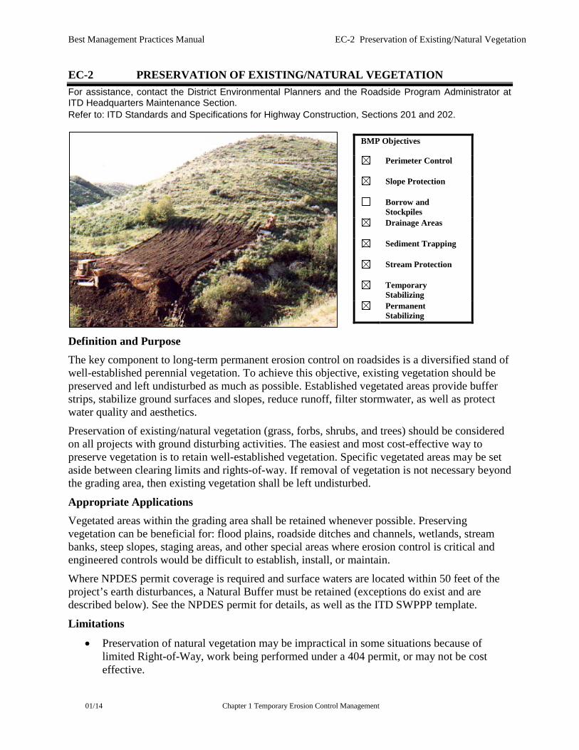
EC-2 PRESERVATION OF EXISTING/NATURAL VEGETATION For assistance, contact the District Environmental Planners and the Roadside Program Administrator at ITD Headquarters Maintenance Section. Refer to: ITD Standards and Specifications for Highway Construction, Sections 201 and 202.
Definition and Purpose The key component to long-term permanent erosion control on roadsides is a diversified stand of well-established perennial vegetation. To achieve this objective, existing vegetation should be preserved and left undisturbed as much as possible. Established vegetated areas provide buffer strips, stabilize ground surfaces and slopes, reduce runoff, filter stormwater, as well as protect water quality and aesthetics.
Preservation of existing/natural vegetation (grass, forbs, shrubs, and trees) should be considered on all projects with ground disturbing activities. The easiest and most cost-effective way to preserve vegetation is to retain well-established vegetation. Specific vegetated areas may be set aside between clearing limits and rights-of-way. If removal of vegetation is not necessary beyond the grading area, then existing vegetation shall be left undisturbed.
Appropriate Applications Vegetated areas within the grading area shall be retained whenever possible. Preserving vegetation can be beneficial for: flood plains, roadside ditches and channels, wetlands, stream banks, steep slopes, staging areas, and other special areas where erosion control is critical and engineered controls would be difficult to establish, install, or maintain.
Where NPDES permit coverage is required and surface waters are located within 50 feet of the project’s earth disturbances, a Natural Buffer must be retained (exceptions do exist and are described below). See the NPDES permit for details, as well as the ITD SWPPP template.
Limitations
• Preservation of natural vegetation may be impractical in some situations because of limited Right-of-Way, work being performed under a 404 permit, or may not be cost effective.
BMP Objectives
Perimeter Control
Slope Protection
Borrow and Stockpiles
Drainage Areas
Sediment Trapping
Stream Protection
Temporary Stabilizing
Permanent Stabilizing

Best Management Practices Manual EC-2 Preservation of Existing/Natural Vegetation
01/14 Chapter 1 Temporary Erosion Control Management
• Local, state, or federal regulations may require specific vegetation to be preserved and protected, including species of concern, threatened or endangered species, and candidate species. The Contractor and ITD personnel shall consult with the appropriate agencies including but not limited to the Idaho Fish and Game (Conservation Data Center), U.S. Fish and Wildlife Service, NOAA-Fisheries, Idaho Department of Lands, and the Idaho Native Plant Society for more information. These species are generally handled through the Environmental Document and may include USFS, BLM, and the Tribes.
Design Parameters
• All construction projects should be designed to preserve existing vegetation to the extent possible or practicable. Preservation activities may involve work staging or sequencing, installing perimeter or other controls/considerations that will preserve existing natural vegetation in certain areas where it would otherwise be removed.
• The Contractor and ITD personnel shall minimize the impact of construction activities on existing vegetation and check the project plans and SWPPP for areas designated for vegetation preservation.
• Areas that will be established for preserving natural vegetation should be clearly identified and delineated onsite, in the plans and specifications and shall be incorporated into the project’s SWPPP. The Contractor shall ensure that existing vegetation remains healthy and undamaged. The Contractor shall replace all damaged vegetation.
• The Contractor and ITD personnel shall keep all construction equipment, materials, and waste out of the designated areas and prevent unauthorized traffic from disturbing the vegetated area.
• Whenever possible, existing drainage patterns through or into the natural area shall left unmodified.
Maintenance and Inspection
• Conduct inspections as required by the NPDES permit or contract specifications.
• Maintain all devices or markings installed to delineate areas to be preserved and protected for the duration of the project.
Best Management Practices Manual EC-3 Coffer Dam
01/14 Chapter 1 Temporary Erosion Control Management
EC-3 COFFER DAM Refer to: ITD Standards and Specifications for Highway Construction, Sections 210 and 501.
Definition and Purpose
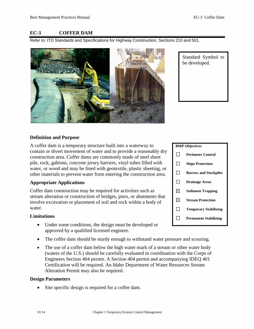
A coffer dam is a temporary structure built into a waterway to contain or divert movement of water and to provide a reasonably dry construction area. Coffer dams are commonly made of steel sheet pile, rock, gabions, concrete jersey barriers, vinyl tubes filled with water, or wood and may be lined with geotextile, plastic sheeting, or other materials to prevent water from entering the construction area.
Appropriate Applications Coffer dam construction may be required for activities such as stream alteration or construction of bridges, piers, or abutments that involve excavation or placement of soil and rock within a body of water.
Limitations
• Under some conditions, the design must be developed or approved by a qualified licensed engineer.
• The coffer dam should be sturdy enough to withstand water pressure and scouring.
• The use of a coffer dam below the high water mark of a stream or other water body (waters of the U.S.) should be carefully evaluated in coordination with the Corps of Engineers Section 404 permit. A Section 404 permit and accompanying IDEQ 401 Certification will be required. An Idaho Department of Water Resources Stream Alteration Permit may also be required.
Design Parameters
• Site specific design is required for a coffer dam.
BMP Objectives
Perimeter Control
Slope Protection
Borrow and Stockpiles
Drainage Areas
Sediment Trapping
Stream Protection
Temporary Stabilizing
Permanent Stabilizing
Standard Symbol to be developed.
Best Management Practices Manual EC-3 Coffer Dam
01/14 Chapter 1 Temporary Erosion Control Management
• Coffer dams should be designed to withstand currents and scour conditions expected under normal stream flow and annual high water. The functional life expectancy is generally 6 months or less.
• Construction materials commonly include steel sheet piles, rock, vinyl tubes, or wood. Piling could consist of standard steel sheet interlocked and driven into the soil or anchored to bedrock. Wooden structures may consist of planks or wood timbers. Concrete jersey barriers may be used, depending on the anticipated water flow, depth and appropriate fit and contact with the stream bed.
• The water side of the coffer dam may be lined with plastic sheeting or some other suitable material that would prevent water passage into the construction area.
• The coffer dam should be built as shown on the plans. Field adjustments shall be made as necessary. Vinyl tubes (bladders) shall be installed following manufacturer’s recommendations and guidelines. Rocks or sharp objects shall be removed prior to installation.
• If dewatering is required while utilizing a coffer dam, meet dewatering requirements of the NPDES permit and/or 404 permit.
Maintenance and Inspection
• Conduct inspections as required by the NPDES or 404 permit or contract specifications.
• Remove accumulated sediment and debris regularly and just prior to removing the coffer dam.
• Conduct required dewatering operations such that all permitting requirements are met.
• Upon removal of the coffer dam, stabilize the area and streambed and restore to as near-natural condition as possible. This may require some form of rock riprap and permanent revegetation if the stream bank has been disturbed.
Best Management Practices Manual EC-4 Diversion Channels/Ditches
01/14 Chapter 1 Temporary Erosion Control Management
EC-4 DIVERSION CHANNELS/INTERCEPTOR DITCHES Refer to: ITD Standards and Specifications for Highway Construction, Sections 208, 209, 212. ITD Standard Drawing P-1-D.
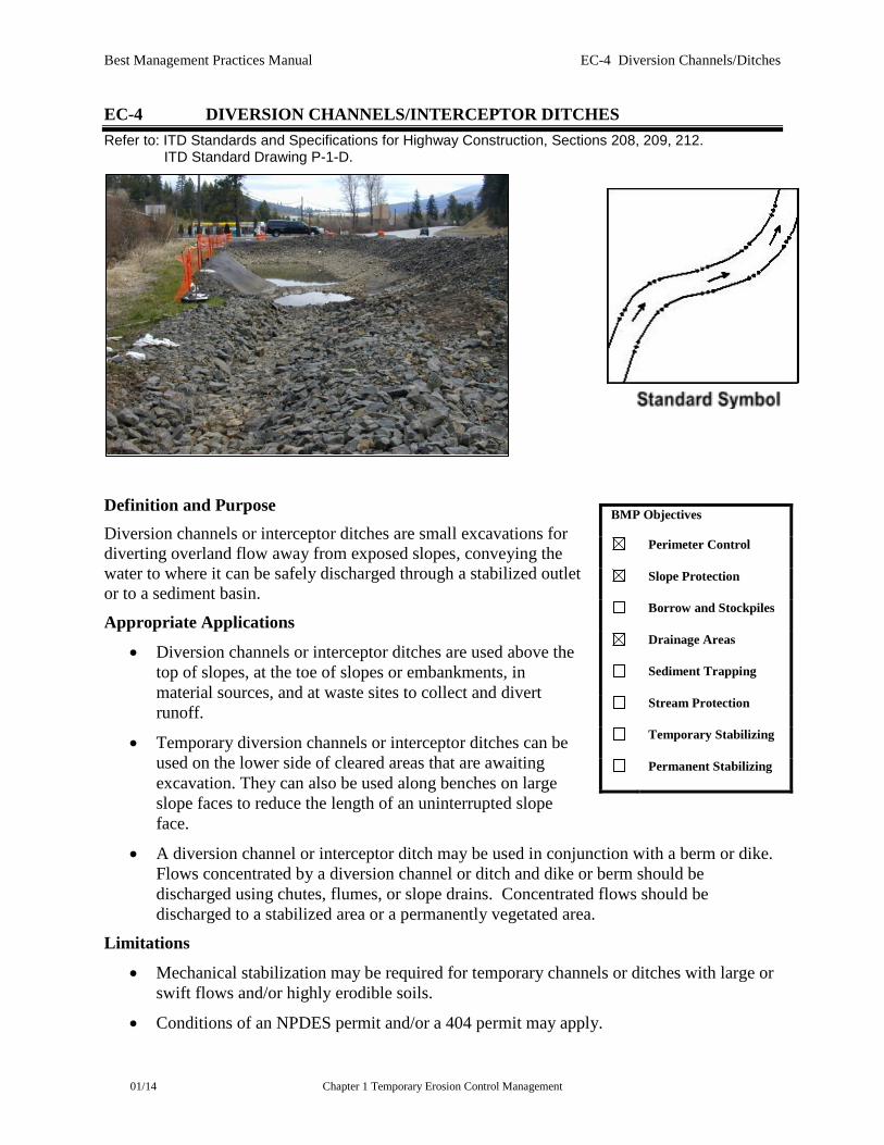
Definition and Purpose Diversion channels or interceptor ditches are small excavations for diverting overland flow away from exposed slopes, conveying the water to where it can be safely discharged through a stabilized outlet or to a sediment basin.
Appropriate Applications
• Diversion channels or interceptor ditches are used above the top of slopes, at the toe of slopes or embankments, in material sources, and at waste sites to collect and divert runoff.
• Temporary diversion channels or interceptor ditches can be used on the lower side of cleared areas that are awaiting excavation. They can also be used along benches on large slope faces to reduce the length of an uninterrupted slope face.
• A diversion channel or interceptor ditch may be used in conjunction with a berm or dike. Flows concentrated by a diversion channel or ditch and dike or berm should be discharged using chutes, flumes, or slope drains. Concentrated flows should be discharged to a stabilized area or a permanently vegetated area.
Limitations
• Mechanical stabilization may be required for temporary channels or ditches with large or swift flows and/or highly erodible soils.
• Conditions of an NPDES permit and/or a 404 permit may apply.
BMP Objectives
Perimeter Control
Slope Protection
Borrow and Stockpiles
Drainage Areas
Sediment Trapping
Stream Protection
Temporary Stabilizing
Permanent Stabilizing
Best Management Practices Manual EC-4 Diversion Channels/Ditches
01/14 Chapter 1 Temporary Erosion Control Management
Design Parameters
• The diversion outlet may be discharged to a non-wetland (preferably vegetated) area, sediment basin, an artificially stabilized area. The diverted runoff should not be allowed to overtop the dike or lip of the ditch. Discharge should be to a flat or gently sloping area and at a non-erosive flow velocity.
• Side slopes of the channel or ditch should be 2H:1V or flatter, and the grade should be gradual.
• The diversion channel or interceptor ditch may consist of a trench and a dike or berm. If a berm or dike is used, it should be compacted as specified.
• Other sediment-control measures, such as sediment basins, ditch checks, etc., may be required to filter or trap sediment before the runoff leaves the site.
• Erosion of channels and their embankments must be minimized through the use of erosion controls and velocity dissipation devices per the NPDES permit.
• Field adjustments shall be made as necessary to ensure proper performance.
Maintenance and Inspection
• Conduct inspections as required by the NPDES permit or contract specifications.
• Repair damaged areas immediately, and remove obstructions.
• Remove the channel or ditch, if it not part of the projects permanent stabilization plan.
• The area feeding runoff to the channel or interceptor ditch shall be permanently stabilized before the channel or ditch is removed.

Best Management Practices Manual EC-5 Slope Drains
01/14 Chapter 1 Temporary Erosion Control Management
EC-5 SLOPE DRAINS Refer to: ITD Standards and Specifications for Highway Construction, Sections 212 and 706. ITD Standard Drawing P-1-A.
Definition and Description
• A slope drain is installed to transport concentrated runoff from the top of a slope to a sediment basin, ditch, or a channel, at the toe of the slope. Water is collected above a disturbed slope (cut or fill) and directed to a collection point at the inlet of the slope drain.
• The use of the slope drain prevents accumulated runoff to flow over slopes that are at high risk of erosion or slope failure. The discharge from the slope drain should be directed into a stabilized water course, riprap, or sediment basin.
Appropriate Applications Slope drains are used primarily during construction whenever runoff needs to be diverted and conveyed down a slope without causing erosion. Slope drains should be used before the slope has been stabilized using a more permanent erosion and sediment control BMP. Slope drain applications may include the following:
• On cut or fill slopes before permanent stormwater drainage structures have been installed.
• Where earth dikes, berms, channels, or ditches have been installed to divert accumulated water from flowing on disturbed slopes.
• On any slope where concentrated runoff crossing the face of the slope may cause gullies, rills, channel erosion, or saturation of slide-prone soils.
• As an outlet for a natural drainage.
BMP Objectives
Perimeter Control
Slope Protection
Borrow and Stockpiles
Drainage Areas
Sediment Trapping
Stream Protection
Temporary Stabilizing
Permanent Stabilizing
Best Management Practices Manual EC-5 Slope Drains
01/14 Chapter 1 Temporary Erosion Control Management
Limitations The area to be drained through the slope drain should not exceed 10 acres. Site specific design and application will be required.
Design Parameters The drainage system, comprised of the diversion measures, inlet, and drain, should be designed (pipe sizing and spacing) to handle the peak runoff for an appropriate design storm event for the project location.
Construction Guidelines
• Install the inlet section of the slope drain at points where water is discharged from ditches, channels, berms, dikes, or other points of concentrated flow.
• Place erosion control geotextiles under the inlet.
• Funnel the flow into the drain. Cross berms and a sediment basin may be needed ahead of the inlet.
• Compact soil around and under the inlet section to the top of the dike or berm to prevent piping failure or undercutting around the inlet.
• Ensure that the finished grade at the inlet is a minimum of 6 inches above the top of the slope drain.
• Place the slope drain on firm, well-compacted soil.
• Anchor all drains to the slope using anchors or stakes to prevent disruption by water or other forces.
• Fasten the slope drain sections securely together and use watertight fittings.
• Extend the pipe beyond the toe of the slope and discharge into a stabilized area or to a sediment basin or pond. Use riprap at the discharge or outlet area to reduce erosion.
• Immediately stabilize the areas disturbed by installation or removal of the slope drain.
• Make field adjustments as necessary to ensure proper performance.
Maintenance and Inspection
• Conduct inspections as required by the NPDES permit or contract specifications. Make necessary repairs immediately if function is compromised.
• Keep construction traffic off the slope drain, and do not place any material on it.
• If necessary, install headwalls or sandbags to prevent bypass flow.
• Install additional outlet protection if needed, and immediately repair breaks and clean out any debris.
• Clean the sediment basin, if provided, when the sediment level reaches one-half the design volume, and dispose of properly per NPDES permit requirements.
• Leave the slope drain in place until the slope has been completely stabilized, or replace with a more permanent slope stabilization measure.
Best Management Practices Manual EC-5 Slope Drains
01/14 Chapter 1 Temporary Erosion Control Management
• Remove the temporary slope drain when the slope is stabilized.
Best Management Practices Manual EC-6 Hydraulically Applied Erosion Control Products
01/14 Chapter 1 Temporary Erosion Control Management
EC-6 HYDRAULICALLY APPLIED EROSION CONTROL PRODUCTS For assistance, contact the District Environmental Planners and the Roadside Program Administrator at ITD Headquarters Maintenance Section. Refer to: ITD Standards and Specifications for Highway Construction, Sections 212, 621 and 711. QPL Category: 621 Erosion Blanket – Liquid Mixture (HECPs)
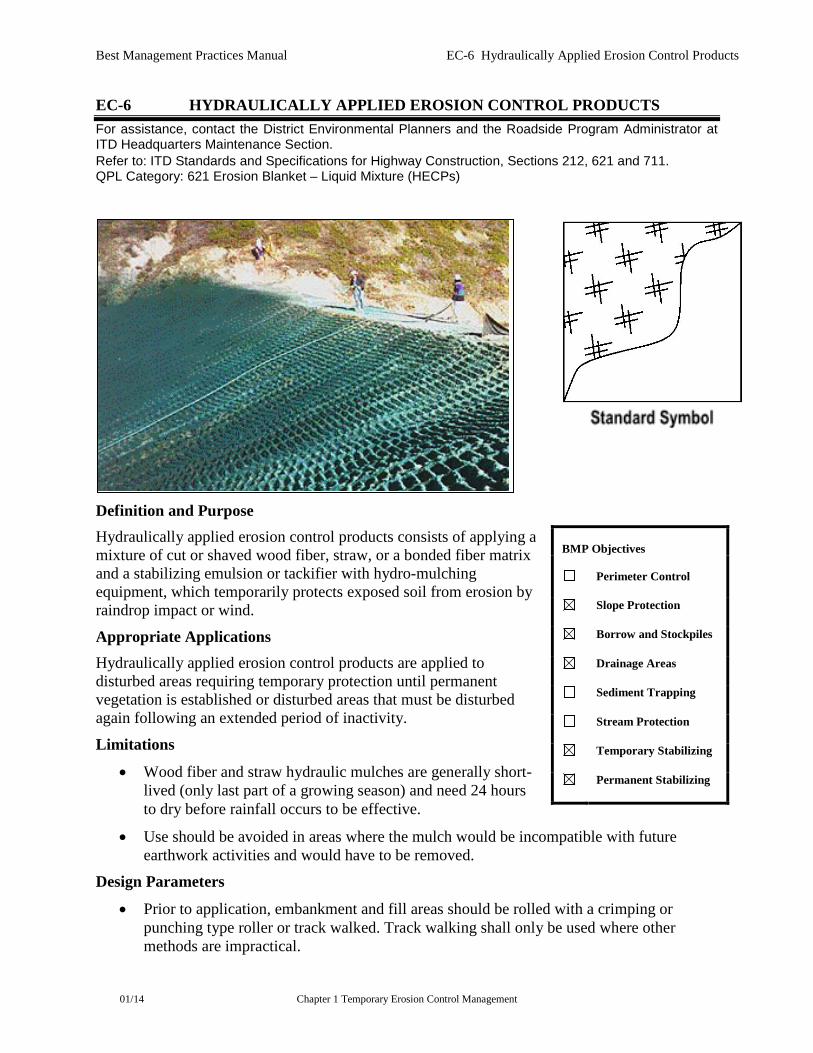
Definition and Purpose Hydraulically applied erosion control products consists of applying a mixture of cut or shaved wood fiber, straw, or a bonded fiber matrix and a stabilizing emulsion or tackifier with hydro-mulching equipment, which temporarily protects exposed soil from erosion by raindrop impact or wind.
Appropriate Applications Hydraulically applied erosion control products are applied to disturbed areas requiring temporary protection until permanent vegetation is established or disturbed areas that must be disturbed again following an extended period of inactivity.
Limitations
• Wood fiber and straw hydraulic mulches are generally short-lived (only last part of a growing season) and need 24 hours to dry before rainfall occurs to be effective.
• Use should be avoided in areas where the mulch would be incompatible with future earthwork activities and would have to be removed.
Design Parameters
• Prior to application, embankment and fill areas should be rolled with a crimping or punching type roller or track walked. Track walking shall only be used where other methods are impractical.
BMP Objectives
Perimeter Control
Slope Protection
Borrow and Stockpiles
Drainage Areas
Sediment Trapping
Stream Protection
Temporary Stabilizing
Permanent Stabilizing

Best Management Practices Manual EC-6 Hydraulically Applied Erosion Control Products
01/14 Chapter 1 Temporary Erosion Control Management
• Hydraulically applied erosion control product over-spray onto the traveled way, sidewalks, lined drainage channels, and existing vegetation shall be avoided.
• Hydraulically applied erosion control products shall be applied per the manufacturer’s recommendations.
• Hydraulic Mulch is a hydraulically-applied material containing defibrated paper, wood, straw and/or natural fibers that may or may not contain tackifier used to provide erosion control and facilitate vegetation establishment on MILD SLOPES (3H:1V max.) and designed to be functional for up to 3 months. Wood mulch is typically applied at the rate of 2,000 to 4,000 pounds/acre. Wood mulch is manufactured from wood or wood waste from lumber mills or from urban sources.
• Stabilized Mulch Matrices (SMM) are a hydraulically-applied matrix containing defibrated organic fibers with, at a minimum, one of the following additives: soil flocculants, cross-linked hydro-colloidal polymers, or cross-linked tackifier. Utilized to provide erosion control and facilitate vegetation establishment on MODERATE SLOPES (2H:1V max.) and designed to be functional for a minimum of 3 months. SMM are applied as a liquid slurry using a hydraulic application machine (i.e., hydro-seeder) at the following typical minimum rates, or as specified by the special provisions, to achieve complete coverage of the target area: 750 pounds/acre wood fiber mulch and 55 gallons/acre of acrylic copolymer.
• Bonded Fiber Matrices (BFM) are a hydraulically-applied matrix of organic defibrated fibers and cross-linked insoluble hydro-colloidal tackifier to provide erosion control and facilitate vegetation establishment on STEEP SLOPES (1H:1V max.) and designed to be functional for a minimum of 6 months. BFMs form an erosion-resistant blanket that promotes vegetation and prevents soil erosion. BFMs are typically applied at rates from 3,000 to 4,000 pounds/acre based on manufacturer’s recommendation (the biodegradable BFM is composed of materials that are 100 percent biodegradable). The binder in the BFM should also be biodegradable and should not dissolve or disperse upon re-wetting. Typically, biodegradable BFMs should not be applied immediately before, during, or immediately after rainfall if the soil is saturated.
• Fiber Reinforced Matrices (FRM) are a hydraulically-applied matrix containing organic defibrated fibers, cross-linked insoluble hydro-colloidal tackifier, and reinforcing natural and/or synthetic fibers to provide erosion control and facilitate vegetation establishment on VERY STEEP SLOPES (0.5H:1V max.) and designed to be functional for a minimum of 12 months.
Qualified Products List Criteria All hydraulically applied erosion control products shall meet the State of Idaho State Department of Agriculture Seed Laboratory or the North American Weed Management Association (NAWMA) noxious weed-free certification requirements prior to approval.
Laboratory and field testing results supporting the manufacturer’s data shall meet the criteria in Table 1 below.
Best Management Practices Manual EC-6 Hydraulically Applied Erosion Control Products
01/14 Chapter 1 Temporary Erosion Control Management
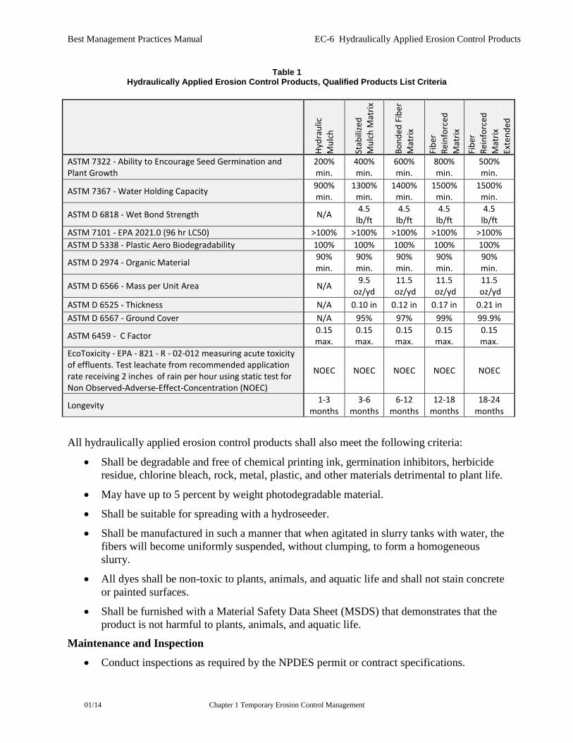
Table 1 Hydraulically Applied Erosion Control Products, Qualified Products List Criteria
All hydraulically applied erosion control products shall also meet the following criteria:
• Shall be degradable and free of chemical printing ink, germination inhibitors, herbicide residue, chlorine bleach, rock, metal, plastic, and other materials detrimental to plant life.
• May have up to 5 percent by weight photodegradable material.
• Shall be suitable for spreading with a hydroseeder.
• Shall be manufactured in such a manner that when agitated in slurry tanks with water, the fibers will become uniformly suspended, without clumping, to form a homogeneous slurry.
• All dyes shall be non-toxic to plants, animals, and aquatic life and shall not stain concrete or painted surfaces.
• Shall be furnished with a Material Safety Data Sheet (MSDS) that demonstrates that the product is not harmful to plants, animals, and aquatic life.
Maintenance and Inspection
• Conduct inspections as required by the NPDES permit or contract specifications.
Hydr
aulic
M
ulch
Stab
ilize
d M
ulch
Mat
rix
Bond
ed F
iber
M
atrix
Fibe
r Re
info
rced
M
atrix
Fibe
r Re
info
rced
M
atrix
Ex
tend
ed
ASTM 7322 - Ability to Encourage Seed Germination and Plant Growth
200% min.
400% min.
600% min.
800% min.
500% min.
ASTM 7367 - Water Holding Capacity 900% min.
1300% min.
1400% min.
1500% min.
1500% min.
ASTM D 6818 - Wet Bond Strength N/A 4.5 lb/ft
4.5 lb/ft
4.5 lb/ft
4.5 lb/ft
ASTM 7101 - EPA 2021.0 (96 hr LC50) >100% >100% >100% >100% >100% ASTM D 5338 - Plastic Aero Biodegradability 100% 100% 100% 100% 100%
ASTM D 2974 - Organic Material 90% min.
90% min.
90% min.
90% min.
90% min.
ASTM D 6566 - Mass per Unit Area N/A 9.5 oz/yd
11.5 oz/yd
11.5 oz/yd
11.5 oz/yd
ASTM D 6525 - Thickness N/A 0.10 in 0.12 in 0.17 in 0.21 in ASTM D 6567 - Ground Cover N/A 95% 97% 99% 99.9%
ASTM 6459 - C Factor 0.15 max.
0.15 max.
0.15 max.
0.15 max.
0.15 max.
EcoToxicity - EPA - 821 - R - 02-012 measuring acute toxicity of effluents. Test leachate from recommended application rate receiving 2 inches of rain per hour using static test for Non Observed-Adverse-Effect-Concentration (NOEC)
NOEC NOEC NOEC NOEC NOEC
Longevity 1-3 months
3-6 months
6-12 months
12-18 months
18-24 months

Best Management Practices Manual EC-6 Hydraulically Applied Erosion Control Products
01/14 Chapter 1 Temporary Erosion Control Management
• Maintain an unbroken, temporary mulched ground cover throughout the period of construction when the soils are not being reworked. Repair any damaged ground cover and re-mulch exposed areas of bare soil.
• The Contractor is responsible for maintaining all slopes to prevent erosion.
Best Management Practices Manual EC-7 Hyrdoseeding
01/14 Chapter 1 Temporary Erosion Control Management
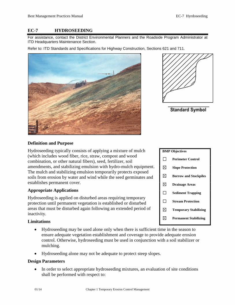
EC-7 HYDROSEEDING For assistance, contact the District Environmental Planners and the Roadside Program Administrator at ITD Headquarters Maintenance Section.
Refer to: ITD Standards and Specifications for Highway Construction, Sections 621 and 711.
Definition and Purpose Hydroseeding typically consists of applying a mixture of mulch (which includes wood fiber, rice, straw, compost and wood combination, or other natural fibers), seed, fertilizer, soil amendments, and stabilizing emulsion with hydro-mulch equipment. The mulch and stabilizing emulsion temporarily protects exposed soils from erosion by water and wind while the seed germinates and establishes permanent cover.
Appropriate Applications Hydroseeding is applied on disturbed areas requiring temporary protection until permanent vegetation is established or disturbed areas that must be disturbed again following an extended period of inactivity.
Limitations
• Hydroseeding may be used alone only when there is sufficient time in the season to ensure adequate vegetation establishment and coverage to provide adequate erosion control. Otherwise, hydroseeding must be used in conjunction with a soil stabilizer or mulching.
• Hydroseeding alone may not be adequate to protect steep slopes.
Design Parameters
• In order to select appropriate hydroseeding mixtures, an evaluation of site conditions shall be performed with respect to:
BMP Objectives
Perimeter Control
Slope Protection
Borrow and Stockpiles
Drainage Areas
Sediment Trapping
Stream Protection
Temporary Stabilizing
Permanent Stabilizing
Best Management Practices Manual EC-7 Hyrdoseeding
01/14 Chapter 1 Temporary Erosion Control Management
Soil types and conditions
Maintenance requirements
Site topography
Sensitive adjacent areas
Season and climate
Water availability
Vegetation types
Plans for permanent vegetation
• Selection of hydroseeding mixtures shall be approved on a project by project basis by a landscape architect or revegetation specialist.
The following steps shall be followed for implementation:
• Hydroseeding is accomplished using a multi-step process. The multi-step process ensures maximum direct contact of the seeds to soil. When applying the mixture of fiber, seed, etc., the seed rate shall be increased to compensate for damage to seed from the hydroseeding equipment or seeds having inadequate direct contact with the soil.
• Prior to application, the slope, fill area, or area to be seeded shall be roughened with the furrows trending along the contours.
• A mulch shall be applied to keep seeds in place and to moderate soil moisture and temperature until the seeds germinate and grow.
• Each seed bag shall be delivered to the site sealed and clearly marked with species, purity, percent germination, dealer's guarantee, and dates of test. This documentation shall be provided to the Engineer. The container shall be labeled to clearly reflect the amount of Pure Live Seed (PLS) contained. All legume seed shall be pellet-inoculated. Inoculant sources shall be species-specific and shall be applied at a typical rate of 2 kg of inoculant per 100 kg of seed (2 percent inoculant by weight).
• Hydroseeding mulch (not including straw mulch, see straw mulch section of EC-9) mixture shall be applied so that seeds and soil are completely covered and there are no visible signs of soil or seeds exposed. The mulch mixture shall be applied at a rate that covers a minimum of 85% of the soil surface. Slurry shall be applied so that it does not run off the soil or down the slope.
• Fertilizer shall be pelleted, granular, or soluble form.
• Follow-up applications shall be made as needed to cover weak spots and to maintain adequate soil protection.
• Over-spray onto the travel way, sidewalks, lined drainage channels and existing vegetation shall be avoided.
Maintenance and Inspection
• Conduct inspections as required by the NPDES permit or contract specifications.
Best Management Practices Manual EC-7 Hyrdoseeding
01/14 Chapter 1 Temporary Erosion Control Management
• All seeded areas shall be re-seeded, fertilized, and mulched within the planting season, using not less than half the original application rates. Any temporary revegetation efforts that do not provide adequate cover must be reapplied as required.
• The Contractor is responsible for maintaining all slopes to prevent erosion.
Best Management Practices Manual EC-8 Soil Binders
01/14 Chapter 1 Temporary Erosion Control Management
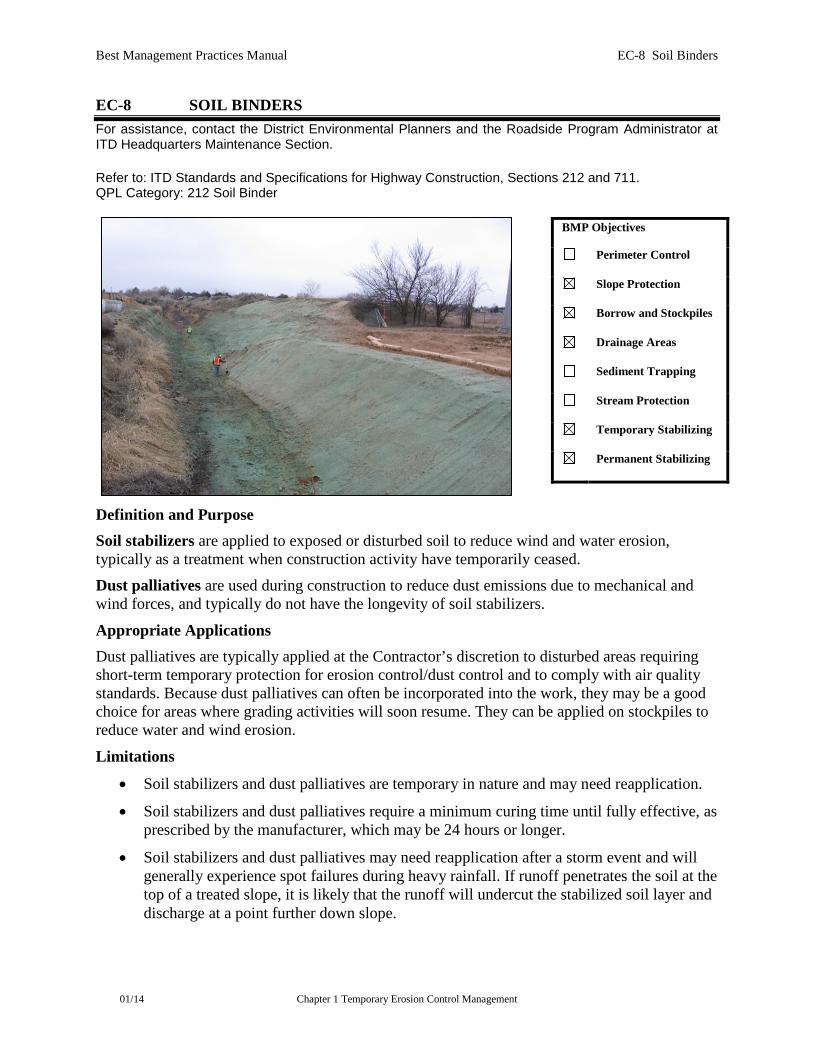
EC-8 SOIL BINDERS For assistance, contact the District Environmental Planners and the Roadside Program Administrator at ITD Headquarters Maintenance Section. Refer to: ITD Standards and Specifications for Highway Construction, Sections 212 and 711. QPL Category: 212 Soil Binder
Definition and Purpose Soil stabilizers are applied to exposed or disturbed soil to reduce wind and water erosion, typically as a treatment when construction activity have temporarily ceased.
Dust palliatives are used during construction to reduce dust emissions due to mechanical and wind forces, and typically do not have the longevity of soil stabilizers.
Appropriate Applications Dust palliatives are typically applied at the Contractor’s discretion to disturbed areas requiring short-term temporary protection for erosion control/dust control and to comply with air quality standards. Because dust palliatives can often be incorporated into the work, they may be a good choice for areas where grading activities will soon resume. They can be applied on stockpiles to reduce water and wind erosion.
Limitations
• Soil stabilizers and dust palliatives are temporary in nature and may need reapplication.
• Soil stabilizers and dust palliatives require a minimum curing time until fully effective, as prescribed by the manufacturer, which may be 24 hours or longer.
• Soil stabilizers and dust palliatives may need reapplication after a storm event and will generally experience spot failures during heavy rainfall. If runoff penetrates the soil at the top of a treated slope, it is likely that the runoff will undercut the stabilized soil layer and discharge at a point further down slope.
BMP Objectives
Perimeter Control
Slope Protection
Borrow and Stockpiles
Drainage Areas
Sediment Trapping
Stream Protection
Temporary Stabilizing
Permanent Stabilizing

Best Management Practices Manual EC-8 Soil Binders
01/14 Chapter 1 Temporary Erosion Control Management
• Some soil stabilizers and dust palliatives do not hold up to pedestrian or vehicular traffic across treated areas. For traffic areas, be sure to select an appropriate product.
• Soil stabilizers and dust palliatives may not penetrate soil surfaces made up primarily of silt and clay, particularly when compacted.
• Some soil stabilizers and dust palliatives may have a deleterious effect on long-term landscaping.
• Some soil stabilizers and dust palliatives may not perform well with low relative humidity. Refer to manufacturers’ literature for humidity limitations. Under rainy conditions, some agents may become slippery or leach out of the soil.
• May not cure if low temperatures occur within 24 hours of application. Refer to manufacturers’ literature for temperature limitations.
General Considerations
• Site-specific soil types will dictate appropriate soil stabilizers or dust palliatives to be used.
• Soil stabilizers and dust palliatives must be environmentally benign (non-toxic to plant and animal life), easy to apply, easy to maintain, economical, and shall not stain paved or painted surfaces.
• Some products are compatible with existing vegetation.
• Performance of soil stabilizers and dust palliatives depends on temperature, humidity, and traffic across treated areas.
• Avoid over-spray onto the traveled way, sidewalks, lined drainage channels, and existing vegetation.
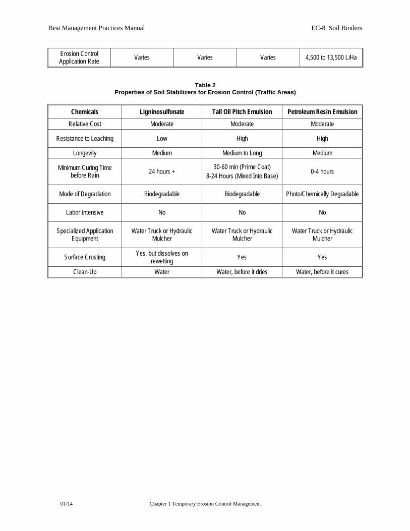
Selecting a Soil Stabilizer or Dust Palliative Properties of common soil stabilizers and dust palliatives used for erosion control are provided in Tables 1 and 2. Use Table 1 to select a product for non-traffic applications, and Table 2 for traffic areas. Refer to EC-14 (Wind Erosion Control) for more information about dust control. Factors to consider when selecting a product include the following:
• Suitability to situation: Consider where the product will be applied, if it needs a high resistance to leaching or abrasion, and whether it needs to be compatible with any existing vegetation. Determine the length of time stabilization will be needed, and if the product will be placed in an area where it will degrade rapidly.
• Soil types and surface materials: Fines and moisture content are key properties of surface materials. Consider a soil stabilizer or dust palliative’s ability to penetrate, likelihood of leaching, and ability to form a surface crust on the surface materials. Soil information can be obtained from the project’s geotechnical report or from a Natural Resources Conservation District (NRCS) website.
• Frequency of application: The frequency of application can be affected by subgrade conditions, surface type, climate, and maintenance schedule. Frequent applications could lead to high costs. Application frequency may be minimized if the dust palliative
Best Management Practices Manual EC-8 Soil Binders
01/14 Chapter 1 Temporary Erosion Control Management
has good penetration, low evaporation, and good longevity. Consider also that frequent application will require frequent equipment clean-up.
Qualified Products List Criteria Shall have a manufacturers’ certification that it is nontoxic to plant or animal life and nonstaining to concrete or painted surfaces.
Plant-Material Based (Short-Lived) Short-lived products may only be used as dust palliatives.
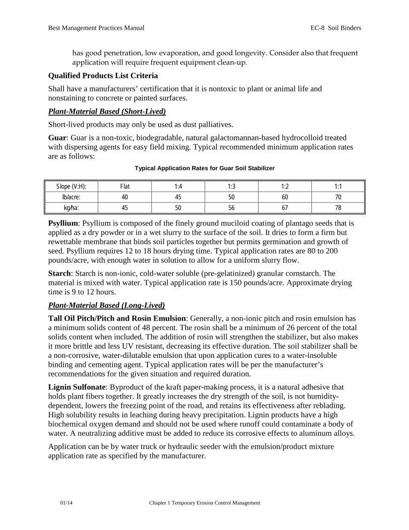
Guar: Guar is a non-toxic, biodegradable, natural galactomannan-based hydrocolloid treated with dispersing agents for easy field mixing. Typical recommended minimum application rates are as follows:
Typical Application Rates for Guar Soil Stabilizer
Slope (V:H): Flat 1:4 1:3 1:2 1:1 lb/acre: 40 45 50 60 70 kg/ha: 45 50 56 67 78
Psyllium: Psyllium is composed of the finely ground muciloid coating of plantago seeds that is applied as a dry powder or in a wet slurry to the surface of the soil. It dries to form a firm but rewettable membrane that binds soil particles together but permits germination and growth of seed. Psyllium requires 12 to 18 hours drying time. Typical application rates are 80 to 200 pounds/acre, with enough water in solution to allow for a uniform slurry flow.
Starch: Starch is non-ionic, cold-water soluble (pre-gelatinized) granular cornstarch. The material is mixed with water. Typical application rate is 150 pounds/acre. Approximate drying time is 9 to 12 hours.
Plant-Material Based (Long-Lived) Tall Oil Pitch/Pitch and Rosin Emulsion: Generally, a non-ionic pitch and rosin emulsion has a minimum solids content of 48 percent. The rosin shall be a minimum of 26 percent of the total solids content when included. The addition of rosin will strengthen the stabilizer, but also makes it more brittle and less UV resistant, decreasing its effective duration. The soil stabilizer shall be a non-corrosive, water-dilutable emulsion that upon application cures to a water-insoluble binding and cementing agent. Typical application rates will be per the manufacturer’s recommendations for the given situation and required duration.
Lignin Sulfonate: Byproduct of the kraft paper-making process, it is a natural adhesive that holds plant fibers together. It greatly increases the dry strength of the soil, is not humidity-dependent, lowers the freezing point of the road, and retains its effectiveness after reblading. High solubility results in leaching during heavy precipitation. Lignin products have a high biochemical oxygen demand and should not be used where runoff could contaminate a body of water. A neutralizing additive must be added to reduce its corrosive effects to aluminum alloys.
Application can be by water truck or hydraulic seeder with the emulsion/product mixture application rate as specified by the manufacturer.
Best Management Practices Manual EC-8 Soil Binders
01/14 Chapter 1 Temporary Erosion Control Management
Polymeric Emulsion Blends Acrylic Copolymers and Polymers: Polymeric soil stabilizers shall consist of a liquid or solid polymer or copolymer with an acrylic base that contains a minimum of 55 percent solids. The polymeric compound shall contain an anti-foaming agent and shall be handled and mixed in a manner that will not cause foaming. The polymeric emulsion shall not exceed its shelf life or expiration date, which will be provided by the manufacturers Polymeric soil stabilizer shall be readily miscible in water, non-injurious to seed or animal life, non-flammable, shall provide surface soil stabilization for various soil types without totally inhibiting water infiltration, and shall not re-emulsify when cured. The applied compound shall air-cure within a maximum of 36 to 48 hours. Liquid copolymer is typically diluted at a rate of 10 parts water to 1 part polymer and applied to soil at a typical rate of 1,175 gallons/acre.
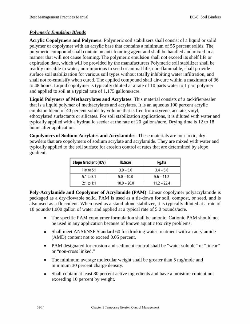
Liquid Polymers of Methacrylates and Acrylates: This material consists of a tackifier/sealer that is a liquid polymer of methacrylates and acrylates. It is an aqueous 100 percent acrylic emulsion blend of 40 percent solids by volume that is free from styrene, acetate, vinyl, ethoxylated surfactants or silicates. For soil stabilization applications, it is diluted with water and typically applied with a hydraulic seeder at the rate of 20 gallons/acre. Drying time is 12 to 18 hours after application. Copolymers of Sodium Acrylates and Acrylamides: These materials are non-toxic, dry powders that are copolymers of sodium acrylate and acrylamide. They are mixed with water and typically applied to the soil surface for erosion control at rates that are determined by slope gradient.
Slope Gradient (H:V) lb/acre kg/ha
Flat to 5:1 3.0 – 5.0 3.4 – 5.6 5:1 to 3:1 5.0 – 10.0 5.6 – 11.2 2:1 to 1:1 10.0 – 20.0 11.2 – 22.4
Poly-Acrylamide and Copolymer of Acrylamide (PAM): Linear copolymer polyacrylamide is packaged as a dry-flowable solid. PAM is used as a tie-down for soil, compost, or seed, and is also used as a flocculent. When used as a stand-alone stabilizer, it is typically diluted at a rate of 10 pounds/1,000 gallon of water and applied at a typical rate of 5.0 pounds/acre.
• The specific PAM copolymer formulation shall be anionic. Cationic PAM should not be used in any application because of known aquatic toxicity problems.
• Shall meet ANSI/NSF Standard 60 for drinking water treatment with an acrylamide (AMD) content not to exceed 0.05 percent.
• PAM designated for erosion and sediment control shall be “water soluble” or “linear” or “non-cross linked.”
• The minimum average molecular weight shall be greater than 5 mg/mole and minimum 30 percent charge density.
• Shall contain at least 80 percent active ingredients and have a moisture content not exceeding 10 percent by weight.
Best Management Practices Manual EC-8 Soil Binders
01/14 Chapter 1 Temporary Erosion Control Management
Hydro-Colloid Polymers: Hydro-Colloid Polymers are various combinations of dry-flowable poly-acrylamides, copolymers and hydro-colloid polymers that are mixed with water and applied to the soil surface at typical rates of 50 to 60 pounds/acre. Drying times are 0 to 4 hours.
Cementitious-Based Gypsum: This is a formulated gypsum-based product that readily mixes with water and sometimes mulch to form a thin protective crust on the soil surface. It is composed of high-purity gypsum that is ground, calcined, and processed into calcium sulfate hemihydrate with a minimum purity of 86 percent. It is mixed in a hydraulic seeder and applied at typical rates of 4,000 to 12,000 pounds/acre. Drying time is 4 to 8 hours.
Petroleum-Based Petroleum Resin Emulsion: These products coat soil particles, increasing their mass and decreasing their likelihood of becoming airborne, but do not exhibit adhesive properties. They are water-insoluble once cured, and hence provide a degree of surface waterproofing and have good residual effectiveness. Used oils are prohibited as a soil stabilizers or dust palliatives, because they contain toxic substances. Petroleum resin products should only be used for traffic areas such as haul roads, parking, and staging areas.
Applying Soil Stabilizers and Dust Palliatives After selecting an appropriate product, the untreated soil surface must be prepared before applying the soil stabilizer. The untreated soil surface must contain sufficient moisture to assist the agent in achieving uniform distribution. In general, the following steps shall be followed:
• Follow manufacturer’s recommendations for application rates and pre-wetting of application area.
• Prior to application, roughen embankment and fill areas. Track walking shall only be used where rolling is impractical.
• Consider the drying time for the selected product and apply with sufficient time before anticipated rainfall. Generally, soil stabilizers and dust palliatives require a minimum curing time of 24 hours before they are fully effective. Refer to manufacturer's instructions for specific cure times. Soil stabilizers and dust palliatives shall not be applied during or immediately before rainfall.
• Avoid over-spray onto the traveled way, sidewalks, lined drainage channels, sound walls, and existing vegetation.
• Soil stabilizers and dust palliatives shall not be applied to frozen soil, areas with standing water, under freezing or rainy conditions, or when the air temperature is below 4°C (40°F) during the curing period.
• More than one treatment is often necessary, although the second treatment may be diluted or have a lower application rate. Follow the manufacturer’s application instructions.
• For liquid agents:
Crown or slope ground to avoid ponding.
Best Management Practices Manual EC-8 Soil Binders
01/14 Chapter 1 Temporary Erosion Control Management
Uniformly pre-wet ground at 0.03 to 0.3 gallon/square yard or according to manufacturer’s recommendations.
Apply solution under pressure. Overlap solution 6 to 12 inches.
Allow treated area to cure for the time recommended by the manufacturer; typically, at least 24 hours.
In areas with low humidity, reactivate chemicals by re-wetting with water at 0.1 to 0.2 gallon per square yard.
Maintenance and Inspections
• Conduct inspections as required by the NPDES permit or contract specifications.
• Reapply the selected soil stabilizer for proper maintenance, as needed.
• After any rainfall event, maintain all slopes to prevent erosion.
• Maintain any unbroken, temporary mulched ground cover while disturbed soil areas are non-active. Repair any damaged ground cover and re-mulch exposed areas.
• Follow manufacturer’s recommendations for maintaining and cleaning equipment after use.
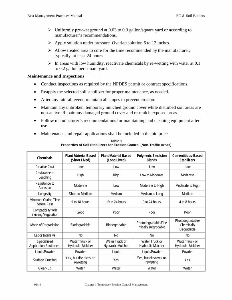
• Maintenance and repair applications shall be included in the bid price. Table 1
Properties of Soil Stabilizers for Erosion Control (Non-Traffic Areas)
Chemicals Plant Material Based (Short Lived)
Plant Material Based (Long Lived)
Polymeric Emulsion Blends
Cementitious-Based Stabilizers
Relative Cost Low Low Low Low Resistance to
Leaching High High Low to Moderate Moderate
Resistance to Abrasion Moderate Low Moderate to High Moderate to High
Longevity Short to Medium Medium Medium to Long Medium Minimum Curing Time
before Rain 9 to 18 hours 19 to 24 hours 0 to 24 hours 4 to 8 hours
Compatibility with Existing Vegetation Good Poor Poor Poor
Mode of Degradation Biodegradable Biodegradable Photodegradable/Chemically Degradable
Photodegradable/ Chemically Degradable
Labor Intensive No No No No Specialized
Application Equipment Water Truck or
Hydraulic Mulcher Water Truck or
Hydraulic Mulcher Water Truck or
Hydraulic Mulcher Water Truck or
Hydraulic Mulcher Liquid/Powder Powder Liquid Liquid/Powder Powder
Surface Crusting Yes, but dissolves on rewetting Yes Yes, but dissolves on
rewetting Yes
Clean-Up Water Water Water Water
Best Management Practices Manual EC-8 Soil Binders
01/14 Chapter 1 Temporary Erosion Control Management
Erosion Control Application Rate Varies Varies Varies 4,500 to 13,500 L/Ha
Table 2 Properties of Soil Stabilizers for Erosion Control (Traffic Areas)
Chemicals Ligninosulfonate Tall Oil Pitch Emulsion Petroleum Resin Emulsion
Relative Cost Moderate Moderate Moderate
Resistance to Leaching Low High High
Longevity Medium Medium to Long Medium
Minimum Curing Time before Rain 24 hours + 30-60 min (Prime Coat)
8-24 Hours (Mixed Into Base) 0-4 hours
Mode of Degradation Biodegradable Biodegradable Photo/Chemically Degradable
Labor Intensive No No No
Specialized Application Equipment
Water Truck or Hydraulic Mulcher
Water Truck or Hydraulic Mulcher
Water Truck or Hydraulic Mulcher
Surface Crusting Yes, but dissolves on rewetting Yes Yes
Clean-Up Water Water, before it dries Water, before it cures
Best Management Practices Manual EC-9 Straw Mulch
01/14 Chapter 1 Temporary Erosion Control Management
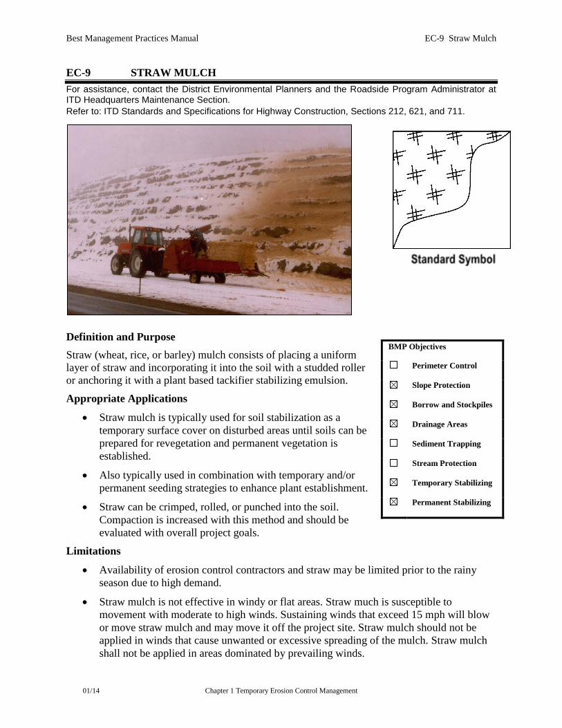
EC-9 STRAW MULCH For assistance, contact the District Environmental Planners and the Roadside Program Administrator at ITD Headquarters Maintenance Section. Refer to: ITD Standards and Specifications for Highway Construction, Sections 212, 621, and 711.
Definition and Purpose Straw (wheat, rice, or barley) mulch consists of placing a uniform layer of straw and incorporating it into the soil with a studded roller or anchoring it with a plant based tackifier stabilizing emulsion.
Appropriate Applications
• Straw mulch is typically used for soil stabilization as a temporary surface cover on disturbed areas until soils can be prepared for revegetation and permanent vegetation is established.
• Also typically used in combination with temporary and/or permanent seeding strategies to enhance plant establishment.
• Straw can be crimped, rolled, or punched into the soil. Compaction is increased with this method and should be evaluated with overall project goals.
Limitations
• Availability of erosion control contractors and straw may be limited prior to the rainy season due to high demand.
• Straw mulch is not effective in windy or flat areas. Straw much is susceptible to movement with moderate to high winds. Sustaining winds that exceed 15 mph will blow or move straw mulch and may move it off the project site. Straw mulch should not be applied in winds that cause unwanted or excessive spreading of the mulch. Straw mulch shall not be applied in areas dominated by prevailing winds.
BMP Objectives
Perimeter Control
Slope Protection
Borrow and Stockpiles
Drainage Areas
Sediment Trapping
Stream Protection
Temporary Stabilizing
Permanent Stabilizing
Best Management Practices Manual EC-9 Straw Mulch
01/14 Chapter 1 Temporary Erosion Control Management
• There is a potential for introduction of weed-seed and unwanted plant material.
• When straw blowers are used to apply straw mulch, the treatment areas must be within 150 feet of a road or surface capable of supporting trucks.
• Straw mulch applied by hand is more time-intensive and potentially costly.
• May have to be removed prior to permanent seeding or soil stabilization.
• Application of straw mulch should be performed in calm conditions with wind speeds below 8 mph.
• When working in sandy soils, pushing the straw into the soils with shovels, discs, or other equipment has limited effectiveness. Other methods, such as the use of plant based tackifier, should be considered to secure the mulch in place.
Design Parameters
• Straw shall be derived from wheat, rice, or barley.
• Straw mulch shall not be applied in areas with moderate to high winds.
• A plant based tackifier is the preferred method for anchoring straw mulch to the soil on slopes. Specifically a guar or plantago based tackifier.
• Crimping, punch roller-type rollers, or track walking may also be used to incorporate straw mulch into the soil on slopes. These measures will help stabilize the straw by burying portions of the stems into the soil. Compaction is increased with this method and the tradeoffs of offsetting surface stability with long-term soil productivity should be considered. Track walking shall only be used where other methods are impractical.
• Placing straw onto the traveled way, sidewalks, lined drainage channels, sound walls, and existing vegetation shall be avoided.
• Straw mulch with plant based tackifier shall not be applied during or immediately before rainfall.
• Straw mulch shall be certified free of any Idaho noxious weeds and shall be certified by an accredited Idaho laboratory or national association such as the North American Weed Management Association.
Application Procedures
• When straw is used as mulch, the application rate should not be applied too deep or in a way that forms a physical barrier that reduces seed germination or establishment. Applying too much straw will restrict sunlight and growing space for establishing seedlings. The minimum acceptable depth is one (1) inch. Straw mulch shall be applied so that 15%-20% of the surface soil is visible through the straw after application.
• Generally, loose straw shall be applied as indicated in the project’s special provisions or manufacturer’s recommendation, either by machine or by hand distribution.
• If stabilizing emulsion will be used to anchor the straw mulch in lieu of incorporation, embankment or fill areas shall be roughened by rolling with a crimping or punching type
Best Management Practices Manual EC-9 Straw Mulch
01/14 Chapter 1 Temporary Erosion Control Management
roller or by track walking, before placing the straw mulch. Track walking should only be used where rolling is impractical and shall be considered when applying duff.
• The straw mulch must be evenly distributed on the soil surface.
• The mulch shall be anchored in place by using a plant based tackifier or by “punching” it into the soil mechanically (incorporating).
• A plant based tackifier acts to glue the straw fibers together and to the soil surface. The plant based tackifier shall be selected based on longevity and ability to hold the fibers in place. Products such as guar and plantago are preferred and used with low quantities of straw mulch to bind the straw together.
• A plant based tackifier is typically applied at a rate of 125 pounds/acre. In windy conditions, the rates are typically 180 pounds/acre.
• Methods for holding the straw mulch in place depend upon the slope steepness, accessibility, soil conditions, and longevity. If the selected method is incorporation of straw mulch into the soil, then do as follows:
On small areas, a spade or shovel can be used.
On slopes with soils that are stable enough and of sufficient gradient to safely support construction equipment without contributing to compaction and instability problems, straw can be punched into the ground using a knife-blade roller or a straight bladed coulter, known commercially as a “crimper.”
On small areas and/or steep slopes, straw can also be held in place using degradable plastic netting or jute. The netting shall be held in place using 11 gauge wire staples, geotextile pins or wooden stakes (as described in EC-11 (Geotextiles, Plastic Covers, and Erosion Control Blankets/Mats).
Maintenance and Inspection
• Inspections shall be conducted as required by the NPDES permit or contract specifications.
• The key consideration in Maintenance and Inspection is that the straw needs to last long enough to achieve erosion control objectives.
• An unbroken, temporary mulched ground cover shall be maintained while disturbed soil areas are non-active. Any damaged ground cover shall be repaired, and exposed areas re-mulched.
• Reapplication of straw mulch and plant based tackifier may be required to maintain effective soil stabilization over disturbed areas and slopes.
• After any rainfall event, the Contractor is responsible for maintaining all slopes to prevent erosion.
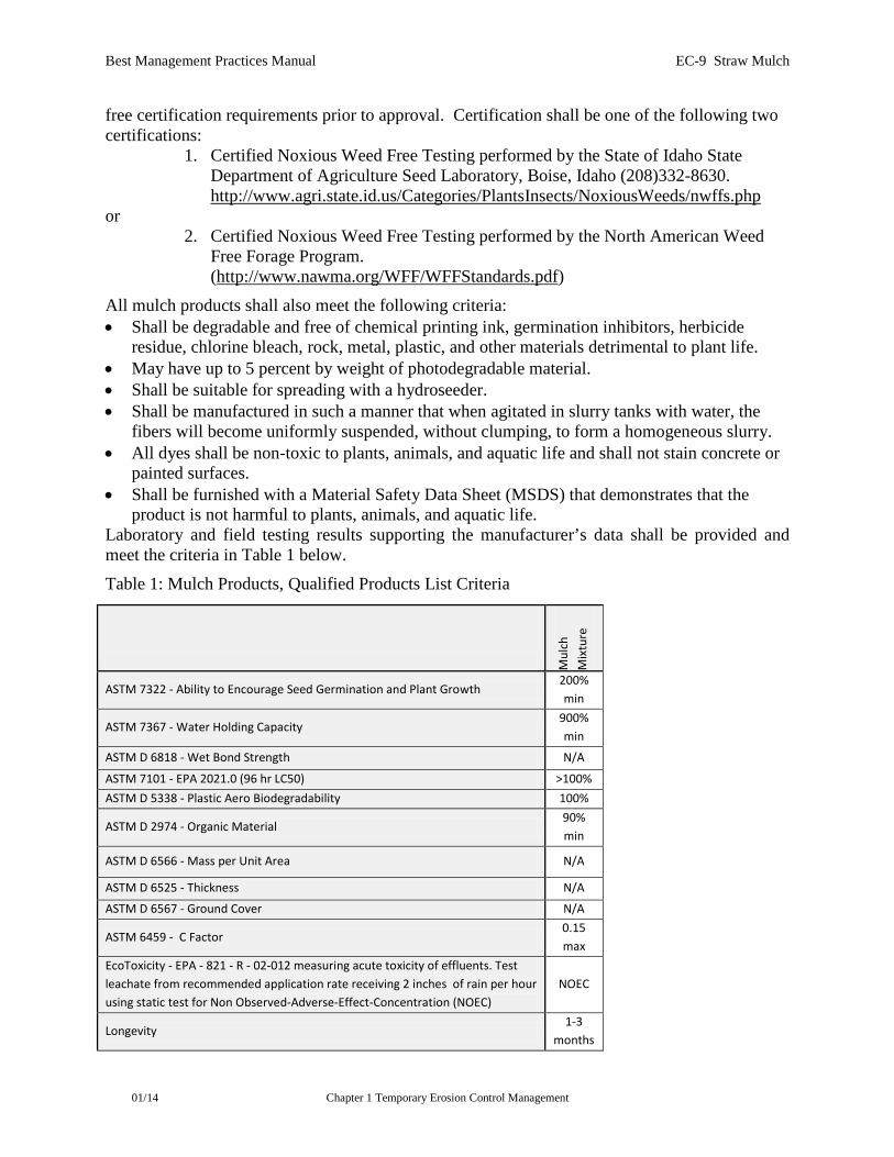
Qualified Products List Criteria All mulch products shall meet the State of Idaho State Department of Agriculture Seed Laboratory or the North American Weed Management Association (NAWMA) noxious weed-
Best Management Practices Manual EC-9 Straw Mulch
01/14 Chapter 1 Temporary Erosion Control Management
free certification requirements prior to approval. Certification shall be one of the following two certifications:
1. Certified Noxious Weed Free Testing performed by the State of Idaho State Department of Agriculture Seed Laboratory, Boise, Idaho (208)332-8630. http://www.agri.state.id.us/Categories/PlantsInsects/NoxiousWeeds/nwffs.php
or 2. Certified Noxious Weed Free Testing performed by the North American Weed
Free Forage Program. (http://www.nawma.org/WFF/WFFStandards.pdf)
All mulch products shall also meet the following criteria: • Shall be degradable and free of chemical printing ink, germination inhibitors, herbicide
residue, chlorine bleach, rock, metal, plastic, and other materials detrimental to plant life. • May have up to 5 percent by weight of photodegradable material. • Shall be suitable for spreading with a hydroseeder. • Shall be manufactured in such a manner that when agitated in slurry tanks with water, the
fibers will become uniformly suspended, without clumping, to form a homogeneous slurry. • All dyes shall be non-toxic to plants, animals, and aquatic life and shall not stain concrete or
painted surfaces. • Shall be furnished with a Material Safety Data Sheet (MSDS) that demonstrates that the
product is not harmful to plants, animals, and aquatic life. Laboratory and field testing results supporting the manufacturer’s data shall be provided and meet the criteria in Table 1 below. Table 1: Mulch Products, Qualified Products List Criteria
Mul
ch
Mix
ture
ASTM 7322 - Ability to Encourage Seed Germination and Plant Growth 200% min
ASTM 7367 - Water Holding Capacity 900% min
ASTM D 6818 - Wet Bond Strength N/A
ASTM 7101 - EPA 2021.0 (96 hr LC50) >100% ASTM D 5338 - Plastic Aero Biodegradability 100%
ASTM D 2974 - Organic Material 90% min
ASTM D 6566 - Mass per Unit Area N/A
ASTM D 6525 - Thickness N/A
ASTM D 6567 - Ground Cover N/A
ASTM 6459 - C Factor 0.15 max
EcoToxicity - EPA - 821 - R - 02-012 measuring acute toxicity of effluents. Test leachate from recommended application rate receiving 2 inches of rain per hour using static test for Non Observed-Adverse-Effect-Concentration (NOEC)
NOEC
Longevity 1-3
months
Best Management Practices Manual EC-10 Wood Mulching
01/14 Chapter 1 Temporary Erosion Control Management
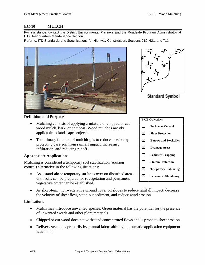
EC-10 MULCH For assistance, contact the District Environmental Planners and the Roadside Program Administrator at ITD Headquarters Maintenance Section. Refer to: ITD Standards and Specifications for Highway Construction, Sections 212, 621, and 711.
Definition and Purpose
• Mulching consists of applying a mixture of chipped or cut wood mulch, bark, or compost. Wood mulch is mostly applicable to landscape projects.
• The primary function of mulching is to reduce erosion by protecting bare soil from rainfall impact, increasing infiltration, and reducing runoff.
Appropriate Applications Mulching is considered a temporary soil stabilization (erosion control) alternative in the following situations:
• As a stand-alone temporary surface cover on disturbed areas until soils can be prepared for revegetation and permanent vegetative cover can be established.
• As short-term, non-vegetative ground cover on slopes to reduce rainfall impact, decrease the velocity of sheet flow, settle out sediment, and reduce wind erosion.
Limitations
• Mulch may introduce unwanted species. Green material has the potential for the presence of unwanted weeds and other plant materials.
• Chipped or cut wood does not withstand concentrated flows and is prone to sheet erosion.
• Delivery system is primarily by manual labor, although pneumatic application equipment is available.
BMP Objectives
Perimeter Control
Slope Protection
Borrow and Stockpiles
Drainage Areas
Sediment Trapping
Stream Protection
Temporary Stabilizing
Permanent Stabilizing
Best Management Practices Manual EC-10 Wood Mulching
01/14 Chapter 1 Temporary Erosion Control Management
• Mulch should not be applied in winds that cause unwanted or excessive spreading of the mulch.
Design Parameters There are many types of mulches, and selection of the appropriate type shall be based on the type of application and site conditions. Mulch use on construction projects may not be compatible with planned or future projects; therefore, the project team shall coordinate with state and local agencies.
Mulch shall be certified free of any Idaho noxious weeds and shall be certified by an accredited state laboratory.
Application Procedures Prior to application, after existing vegetation has been removed, roughen embankment and fill areas by rolling with a punching type roller or by track walking. The construction-application procedures for mulches vary significantly depending upon the type of mulching method specified. Two methods are highlighted here:
• Green material is produced by recycling vegetation trimmings such as chipped or cut shrubs and trees. Methods of application are generally by hand, although pneumatic methods are available. Materials composted must be indigenous. Noxious weeds shall not be composted. Compost shall not contain any viable noxious weed seed.
It can be used as a temporary ground cover with or without seeding.
The green material shall be evenly distributed on-site to a depth of not more than 2 in.
• Chipped or cut wood is suitable for ground cover in ornamental or revegetated plantings.
Is conditionally suitable; see note under Limitations section above.
Shall be distributed by hand or another method approved by the Engineer.
Shall be evenly distributed across the soil surface to a depth of 3 inches.
• Wood fiber mulches are suitable with seeding and plantings on revegetation projects. Wood fiber mulches can also be used and mixed with compost and applied as compost/wood mulch. Wood fiber mulches are applied with special hydroseeding or mulch blowing equipment. The amount of wood fiber mulch depends on the project. Typically for seedings, the application rate ranges from 100 yd³/ac (applied at 0.75 inch thickness) to 135 yd³ (applied at 1 inch thickness). For seedlings, mulch application ranges from 400 yd³ (applied at 3 inch thickness) to 540 yd³ (applied at 4 inch thickness; the higher rate is only used in close proximity to the plants).
Long-fiber mulch – forms large air spaces and can be applied at a greater thickness which helps maintain surface soil moisture and humidity around germinating seeds and emerging seedlings. Long fiber mulch also allows sunlight penetration which enhances seed germination and seedling establishment.
Short-fiber – have smaller pores and form denser seed cover. Short-fiber mulch is typically applied thinly and offer less insulation for germinating seeds and emerging seedlings. Short-fiber mulches are effective as an erosion control cover

Best Management Practices Manual EC-10 Wood Mulching
01/14 Chapter 1 Temporary Erosion Control Management
but are considered inferior to long-fiber mulches for germination and early seedling establishment.
• Mulch placement onto the traveled way, sidewalks, lined drainage channels, sound walls, and existing vegetation shall be avoided.
• All material must be removed prior to re-starting work on the slopes. In some cases, wood mulch may be incorporated into the soil if approved by the Engineer.
• Mulch material should come from indigenous plants only.
Maintenance and Inspection
• Inspections shall be conducted as required by the NPDES permit or contract specifications.
• Regardless of the mulching technique selected, the key consideration in Maintenance and Inspection is that the mulch needs to last long enough to achieve erosion-control objectives. If the mulch is applied as a stand-alone erosion control method over disturbed areas (without seed), it shall last the length of time the site will remain barren or until final re-grading and revegetation.
• Where vegetation is not the ultimate cover, such as ornamental and landscape applications of bark or wood chips, maintenance shall focus on longevity and integrity of the mulch.
Qualified Products List Criteria See QPL Criteria 621.
All mulch products shall meet the State of Idaho State Department of Agriculture Seed Laboratory or the North American Weed Management Association (NAWMA) noxious weed-free certification requirements prior to approval. Certification shall be one of the following two certifications:
1. Certified Noxious Weed Free Testing performed by the State of Idaho State Department of Agriculture Seed Laboratory, Boise, Idaho (208)332-8630. http://www.agri.state.id.us/Categories/PlantsInsects/NoxiousWeeds/nwffs.php
or 2. Certified Noxious Weed Free Testing performed by the North American Weed
Free Forage Program. (http://www.nawma.org/WFF/WFFStandards.pdf)
All mulch products shall also meet the following criteria: • Shall be degradable and free of chemical printing ink, germination inhibitors, herbicide
residue, chlorine bleach, rock, metal, plastic, and other materials detrimental to plant life. • May have up to 5 percent by weight of photodegradable material. • Shall be manufactured in such a manner that when agitated in slurry tanks with water, the
fibers will become uniformly suspended, without clumping, to form a homogeneous slurry. • All dyes shall be non-toxic to plants, animals, and aquatic life and shall not stain concrete or
painted surfaces. • Shall be furnished with a Material Safety Data Sheet (MSDS) that demonstrates that the
product is not harmful to plants, animals, and aquatic life.

Best Management Practices Manual EC-10 Wood Mulching
01/14 Chapter 1 Temporary Erosion Control Management
Laboratory and field testing results supporting the manufacturer’s data shall meet the criteria in Table 1 below:
Table 1: Mulch Products, Qualified Products List Criteria
M
ulch
M
ixtu
re
ASTM 7322 - Ability to Encourage Seed Germination and Plant Growth 200% min
ASTM 7367 - Water Holding Capacity 900% min
ASTM D 6818 - Wet Bond Strength N/A
ASTM 7101 - EPA 2021.0 (96 hr LC50) >100% ASTM D 5338 - Plastic Aero Biodegradability 100%
ASTM D 2974 - Organic Material 90% min
ASTM D 6566 - Mass per Unit Area N/A
ASTM D 6525 - Thickness N/A
ASTM D 6567 - Ground Cover N/A
ASTM 6459 - C Factor 0.15 max
EcoToxicity - EPA - 821 - R - 02-012 measuring acute toxicity of effluents. Test leachate from recommended application rate receiving 2 inches of rain per hour using static test for Non Observed-Adverse-Effect-Concentration (NOEC)
NOEC
Longevity 1-3
months
Best Management Practices Manual EC-11 Geotextiles, Plastic Covers & Erosion Control Blankets/Mats
01/14 Chapter 1 Temporary Erosion Control Management
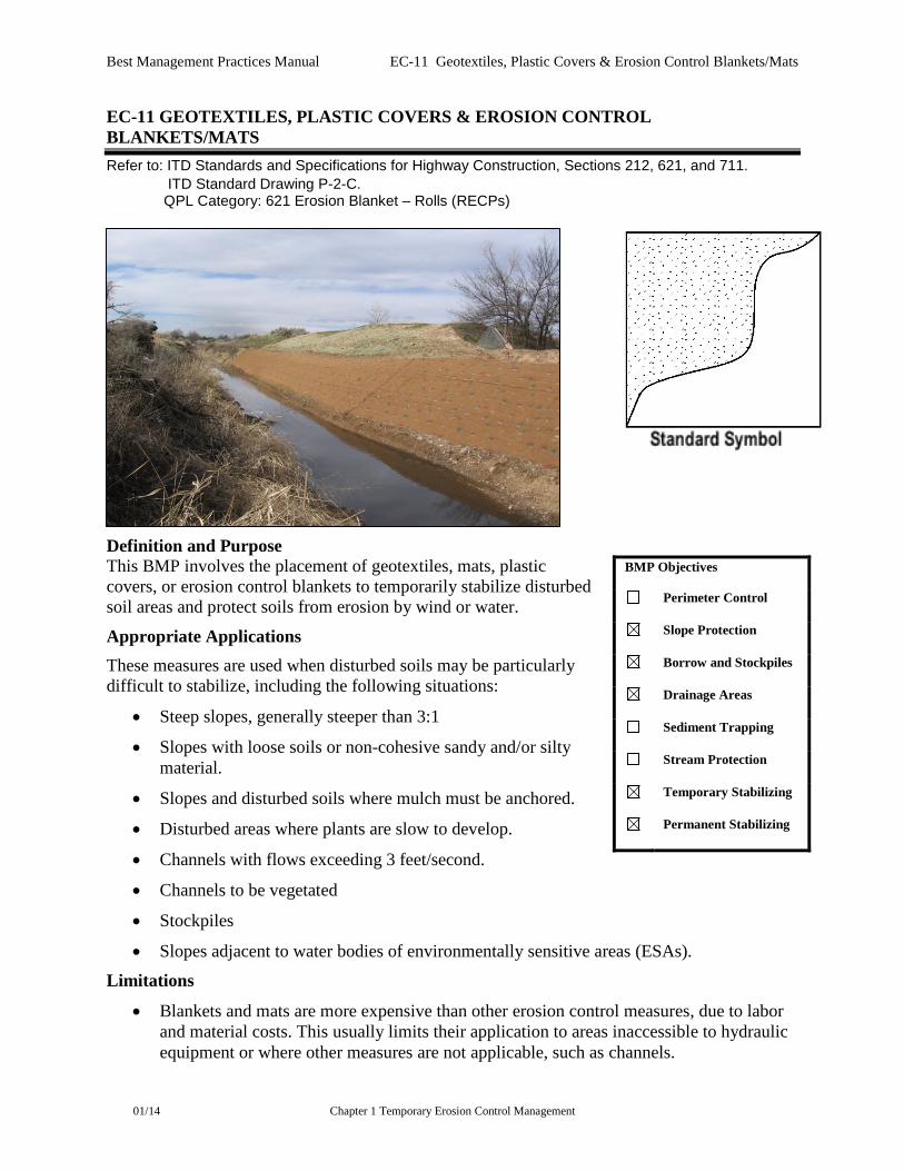
EC-11 GEOTEXTILES, PLASTIC COVERS & EROSION CONTROL BLANKETS/MATS Refer to: ITD Standards and Specifications for Highway Construction, Sections 212, 621, and 711. ITD Standard Drawing P-2-C. QPL Category: 621 Erosion Blanket – Rolls (RECPs)
Definition and Purpose This BMP involves the placement of geotextiles, mats, plastic covers, or erosion control blankets to temporarily stabilize disturbed soil areas and protect soils from erosion by wind or water.
Appropriate Applications These measures are used when disturbed soils may be particularly difficult to stabilize, including the following situations:
• Steep slopes, generally steeper than 3:1
• Slopes with loose soils or non-cohesive sandy and/or silty material.
• Slopes and disturbed soils where mulch must be anchored.
• Disturbed areas where plants are slow to develop.
• Channels with flows exceeding 3 feet/second.
• Channels to be vegetated
• Stockpiles
• Slopes adjacent to water bodies of environmentally sensitive areas (ESAs).
Limitations
• Blankets and mats are more expensive than other erosion control measures, due to labor and material costs. This usually limits their application to areas inaccessible to hydraulic equipment or where other measures are not applicable, such as channels.
BMP Objectives
Perimeter Control
Slope Protection
Borrow and Stockpiles
Drainage Areas
Sediment Trapping
Stream Protection
Temporary Stabilizing
Permanent Stabilizing
Best Management Practices Manual EC-11 Geotextiles, Plastic Covers & Erosion Control Blankets/Mats
01/14 Chapter 1 Temporary Erosion Control Management
• Blankets and mats are generally not suitable for excessively rocky sites or areas where the final vegetation will be mowed (because staples and netting can catch in mowers).
• Plastic sheeting is easily vandalized, easily torn, photodegradable, and must be disposed of at a landfill.
• Non-degradable fabrics must generally be removed when permanent stabilization measures are ready to be installed. Failure to move these materials creates trash that may be environmentally harmful and may result in littering fines.
• Plastic results in 100 percent runoff, which may cause serious erosion problems in the areas receiving the concentrated sheet flow.
• The use of plastic should be limited to covering stockpiles, or very small graded areas for short periods of time (such as through one imminent storm event), until alternative measures, such as seeding and mulching, may be installed.
• Geotextiles, mats, plastic covers, and erosion control covers have maximum flow rate limitations. The manufacturer shall be consulted for proper selection.
Material Selection There are many types of erosion control blankets and mats, and selection of the appropriate type shall be based on the specific type of application and site conditions.
Geotextiles
• A wide variety of Geotextiles are available, dependent on their intended uses which range from separation of different materials (such as road bedding and underlying soils) to lining ponds and landfills. For temporary erosion control, geotextile fabrics typically consist of woven or non-woven fabrics that are used to line channels or slopes and are usually used in combination with rock or other mulches or riprap.
• Geomembrane is a more impervious type of geotextile and can be used to cover stockpiles or bare soil areas, where a more durable material (as compared to plastic sheeting) is desired. The use of geomembranes for this application will likely be very limited due to their higher costs.
• Geotextiles should be secured in place with wire staples or sandbags and by keying into tops of slopes and edges to prevent infiltration of surface waters under Geotextile. Staples shall be made of 0.12-inch steel wire and shall be U-shaped with 8-inch legs and 2-inch crown.
• Geotextiles may be reused if, in the opinion of the Engineer, they are suitable for the use intended.
Plastic Covers
• Plastic sheeting shall have a minimum thickness of 6 millimeters and shall be keyed in at the top of slope and firmly held in place with sandbags or other weights placed no more than 10 feet apart. Seams are typically taped or weighted down their entire length, and there shall be at least a 12 to 24 inches overlap of all seams. Edges shall be embedded a minimum of 6 inches in soil.
Best Management Practices Manual EC-11 Geotextiles, Plastic Covers & Erosion Control Blankets/Mats
01/14 Chapter 1 Temporary Erosion Control Management
• Any sheeting failures shall be repaired immediately. If washout or breakages occur, the material shall be re-installed after repairing the damage to the slope.
Erosion Control Blankets/Mats (Rolled Erosion Control Products) Degradable rolled erosion control products (RECPs) are typically composed of jute fibers, curled wood fibers, straw, coconut fiber, or a combination of these materials. In order for an RECP to be considered 100 percent degradable, the netting, sewing or adhesive system that holds the biodegradable mulch fibers together must also be degradable.
• Jute is a natural fiber that is made into a yarn that is loosely woven into a biodegradable mesh. It is designed to be used in conjunction with vegetation and has longevity of approximately 1 year. The material is supplied in rolled strips, which shall be secured to the soil with U-shaped staples or stakes in accordance with manufacturers’ recommendations.
• Excelsior (curled wood fiber) blanket material shall consist of machine-produced mats of curled wood excelsior. The excelsior blanket shall be of consistent thickness. The wood fiber shall be evenly distributed over the entire area of the blanket. The top surface of the blanket shall be covered with a photodegradable extruded plastic mesh. The blanket shall be smolder-resistant without the use of chemical additives and shall be non-toxic and non-injurious to plant and animal life. Excelsior blanket shall be furnished in rolled strips.
• Straw blanket shall be machine-produced mats of straw with a lightweight degradable netting top layer. The straw shall be attached to the netting with degradable thread or glue strips. The straw blanket shall be of consistent thickness. The straw shall be evenly distributed over the entire area of the blanket. Straw blanket shall be furnished in rolled strips.
• Wood fiber blanket is composed of biodegradable fiber mulch with extruded plastic netting held together with adhesives. The material is designed to enhance revegetation. The material is furnished in rolled strips, which shall be secured to the ground with U-shaped staples or stakes in accordance with manufacturers’ recommendations.
• Coconut fiber blanket shall be machine-produced mats of 100 percent coconut fiber with degradable netting on the top and bottom. The coconut fiber shall be attached to the netting with degradable thread or glue strips. The coconut fiber blanket shall be of consistent thickness. The coconut fiber shall be evenly distributed over the entire area of the blanket. Coconut fiber blanket shall be furnished in rolled.
• Coconut fiber mesh is a thin permeable membrane made from coconut or corn fiber that is spun into a yarn and woven into a degradable mat. It is designed to be used in conjunction with vegetation and typically has longevity of several years. The material is supplied in rolled strips, which shall be secured to the soil with U-shaped staples or stakes in accordance with manufacturers’ recommendations.
• Straw coconut fiber blanket shall be machine-produced mats of 70 percent straw and 30 percent coconut fiber with a degradable netting top layer and a degradable bottom net. The straw and coconut fiber shall be attached to the netting with degradable thread or glue strips. The straw coconut fiber blanket shall be of consistent thickness and shall be
Best Management Practices Manual EC-11 Geotextiles, Plastic Covers & Erosion Control Blankets/Mats
01/14 Chapter 1 Temporary Erosion Control Management
evenly distributed over the entire area of the blanket. Straw coconut fiber blanket shall be furnished in rolled strips.
Non-degradable RECPs are typically composed of polyethylene, polypropylene, nylon, or other synthetic fibers. In some cases, a combination of degradable and synthetic fibers is used to construct the RECP. Netting used to hold these fibers together is typically non-degradable as well.
• Plastic netting is a lightweight biaxially-oriented netting designed for securing loose mulches like straw or paper to soil surfaces to establish vegetation. The netting is photodegradable. The netting is supplied in rolled strips, which shall be secured with U-shaped staples or stakes in accordance with manufacturers’ recommendations.
• Plastic mesh is an open-weave geotextile that is composed of an extruded synthetic fiber woven into a mesh with an opening size of less than 2 inches. It is used with revegetation or may be used to secure loose fiber such as straw to the ground. The material is supplied in rolled strips, which shall be secured to the soil with U-shaped staples or stakes in accordance with manufacturers’ recommendations.
• Synthetic fiber with netting is a mat that is composed of durable synthetic fibers treated to resist chemicals and ultraviolet light. The mat is a dense, three-dimensional mesh of synthetic (typically polyolefin) fibers stitched between two polypropylene nets. The mats are designed to be revegetated and provide a permanent composite system of soil, roots, and geomatrix. The material is furnished in rolled strips, which shall be secured with U-shaped staples or stakes in accordance with manufacturers’ recommendations.
• Bonded synthetic fibers consist of a three-dimensional geomatrix nylon (or other synthetic) matting. Typically, it has more than 90 percent open area, which facilitates root growth. Its tough root-reinforcing system anchors vegetation and protects against hydraulic lift and shear forces created by high volume discharges. It can be installed over prepared soil, followed by seeding into the mat. Once vegetated, it becomes an invisible composite system of soil, roots, and geomatrix. The material is furnished in rolled strips that shall be secured with U-shaped staples or stakes in accordance with manufacturers’ recommendations.
• Combination synthetic and biodegradable RECPs consist of biodegradable fibers, such as wood fiber or coconut fiber, with a heavy polypropylene net stitched to the top and a high-strength continuous-filament geomatrix or net stitched to the bottom. The material is designed to enhance revegetation. The material is furnished in rolled strips, which shall be secured with U-shaped staples or stakes in accordance with manufacturers’ recommendations.
Qualified Products List Criteria All rolled erosion control products shall meet the State of Idaho State Department of Agriculture Seed Laboratory or the North American Weed Management Association (NAWMA) noxious weed-free certification requirements prior to approval.
All RECPs shall: • Have independents test results submitted shall be from either the National Transportation
Product Evaluation Program (NTPEP) or an approved equivalent laboratory.

Best Management Practices Manual EC-11 Geotextiles, Plastic Covers & Erosion Control Blankets/Mats
01/14 Chapter 1 Temporary Erosion Control Management
Site Preparation
• Prepare the site properly to ensure complete contact of the blanket or matting with the soil.
• Grade and shape the area of installation.
• Remove all rocks, clods, vegetation, or other obstructions so that the installed blankets or mats will have complete, direct contact with the soil.
• Prepare seedbed by loosening 2 to 3 inches of topsoil. When using a fabric or mat that is designed to be used in conjunction with seeding or revegetation, follow the manufacturer’s guidelines for proper seedbed preparation, seed application, and/or planting.
Seeding Seed the area before blanket installation for erosion control and revegetation. Seeding after mat installation is often specified for turf reinforcement application. When seeding prior to blanket installation, all check slots and other areas disturbed during installation must be re-seeded. Where soil filling is specified, seed the matting and the entire disturbed area after installation and prior to filling the mat with soil.
Anchoring
• U-shaped wire staples, metal geotextile stake pins, or triangular wooden stakes can be used to anchor mats and blankets to the ground surface.
• Wire staples and metal stakes shall be driven flush to the soil surface.
• All anchors shall be a minimum of 6 inches long and have sufficient penetration to resist pullout. Longer anchors may be required for loose soils as determined by the responsible party or by manufacturer’s installation guidelines.
Installation on Slopes Installation shall be in accordance with the manufacturer’s recommendations or ITD Standard Drawing P-2-C.
Installation in Channels Installation shall be in accordance with the manufacturer’s recommendations or ITD Standard Drawing P-2-C.
Soil Filling (if specified for turf reinforcement)
• Always consult the manufacturer’s recommendations for installation.
• Do not drive tracked or heavy equipment over mat.
• Avoid any traffic over matting if loose or wet soil conditions exist.
• Use shovels, rakes, or brooms for fine grading and touch up.
• Smooth out soil filling, just exposing top netting of mat.
Best Management Practices Manual EC-11 Geotextiles, Plastic Covers & Erosion Control Blankets/Mats
01/14 Chapter 1 Temporary Erosion Control Management
Blanket Removal When no longer required for work, non-degradable temporary blankets shall be removed from the site and disposed.
Maintenance and Inspection
• Inspections shall be conducted as required by the NPDES permit or contract specifications.
• Areas treated with temporary geotextiles, mats, blankets, and other covers shall be maintained to provide adequate erosion control. Any failures shall be repaired immediately.
• If washout or breakage occurs, reinstall the material after repairing the damage to the slope or channel.
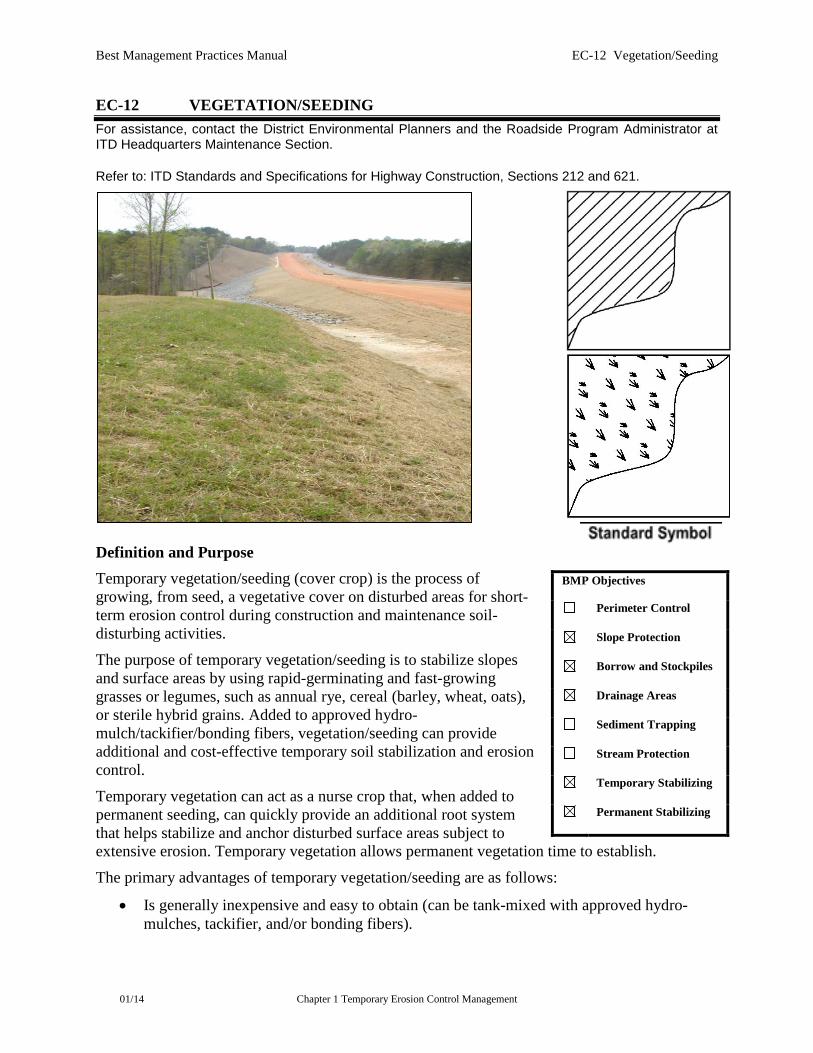
Best Management Practices Manual EC-12 Vegetation/Seeding
01/14 Chapter 1 Temporary Erosion Control Management
EC-12 VEGETATION/SEEDING For assistance, contact the District Environmental Planners and the Roadside Program Administrator at ITD Headquarters Maintenance Section. Refer to: ITD Standards and Specifications for Highway Construction, Sections 212 and 621.
Definition and Purpose Temporary vegetation/seeding (cover crop) is the process of growing, from seed, a vegetative cover on disturbed areas for short-term erosion control during construction and maintenance soil-disturbing activities.
The purpose of temporary vegetation/seeding is to stabilize slopes and surface areas by using rapid-germinating and fast-growing grasses or legumes, such as annual rye, cereal (barley, wheat, oats), or sterile hybrid grains. Added to approved hydro-mulch/tackifier/bonding fibers, vegetation/seeding can provide additional and cost-effective temporary soil stabilization and erosion control.
Temporary vegetation can act as a nurse crop that, when added to permanent seeding, can quickly provide an additional root system that helps stabilize and anchor disturbed surface areas subject to extensive erosion. Temporary vegetation allows permanent vegetation time to establish.
The primary advantages of temporary vegetation/seeding are as follows:
• Is generally inexpensive and easy to obtain (can be tank-mixed with approved hydro-mulches, tackifier, and/or bonding fibers).
BMP Objectives
Perimeter Control
Slope Protection
Borrow and Stockpiles
Drainage Areas
Sediment Trapping
Stream Protection
Temporary Stabilizing
Permanent Stabilizing
Best Management Practices Manual EC-12 Vegetation/Seeding
01/14 Chapter 1 Temporary Erosion Control Management
• Quickly provides effective soil stabilization when conditions (favorable precipitation and temperatures) are conducive to good germination and plant growth.
• Adds to permanent seeding as a nurse crop or can be over-seeded with permanent seeding
• Provides a quicker short-term vegetative growth that will assist in erosion control until the permanent vegetation starts to grow and becomes established.
• Retards the invasion and growth of undesirable weeds and provides good aesthetic qualities.
• Complements other temporary BMP erosion control measures (reduces sedimentation and the cost associated [during construction] with maintenance of other erosion control measures, such as cleaning out in front of ditch checks and sediment trap basins).
• Can be repaired or reseeded after disturbance.
Appropriate Applications
• Typical disturbed areas to consider for temporary vegetation are slides, washouts, slopes, guttering, topsoil stockpiles, temporary excavation or embankment areas, dikes, berms, dams, sediment trap basins (sides and top), and road banks.
• Temporary vegetation should be considered for any disturbed area where the potential for erosion may occur or where the disturbed area is required to receive a temporary soil stabilization BMP because of exposure to stormwater or wind after the last construction or maintenance activity (time limitation).
• Temporary vegetation can also be applied on surface areas prior to permanent vegetation to allow permanent seeding to take place at the appropriate times (season of seeding).
Limitations Establishment of temporary vegetation depends on favorable temperatures and precipitation. The optimum time for establishing temporary vegetation is usually in the spring (February-April) or fall (October-November). Unless establishment water is used, temporary seeding in the summer months (May-September) is usually not effective and other temporary soil stabilizations and erosion control BMPs should be considered or relied upon. The same limitation applies to temporary seeding on frozen ground or in deep snow.
Design Parameters
• Temporary vegetation should be utilized in combination with other temporary erosion control practices. Vegetation/seeding would consist of the hydro application of approved seed (optional), soil binders, tackifier, bonding fibers, and wood fiber mulch at the prescribed rate.
• Some soil binders and tackifier will impede or interfere with seed germination and plant growth.
• Additional information can be obtained from TN Plant Materials No. 24, Improved Grass, Forb, Legume, and Woody Seed Species for The Intermountain West (USDA – Natural Resources Conservation Service) FHWA Roadside Revegetation Manual, the
Best Management Practices Manual EC-12 Vegetation/Seeding
01/14 Chapter 1 Temporary Erosion Control Management
ITD Roadside Revegetation Handbook, or the ITD Native Plants for Idaho Roadside Restoration and Revegetation Programs.
• Temporary vegetation should be non-persistent and non-invasive.
Construction Guidelines
• Install structural or more permanent erosion control practices, such as dikes, basins, and berms before seeding.
• Use clean, high-quality certified seed. Ensure proper selection of seed through coordination with appropriate ITD Roadside Program Administrator.
• Loosen compacted soil prior to seeding.
• Mix the temporary seed with other approved soil stabilization and erosion control products to provide better erosion control results. In the event that the seeding fails, the other products may provide the required temporary erosion control.
• Re-seed when necessary.
• Make field adjustments as necessary to ensure proper performance.
Maintenance and Inspection
• Conduct inspections as required by the NPDES permit or contract specifications.
• Check for areas where protective measures (such as mulches or matting) have failed, or where plant growth is not proceeding at the desired rate. Apply seed or other treatments immediately.
• Removal of temporary vegetation prior to a more permanent BMP such as permanent seeding is usually not necessary. If temporary vegetation is too high for a permanent vegetation application to come into positive contact with the soil, mowing or cutting the temporary vegetation may be required.
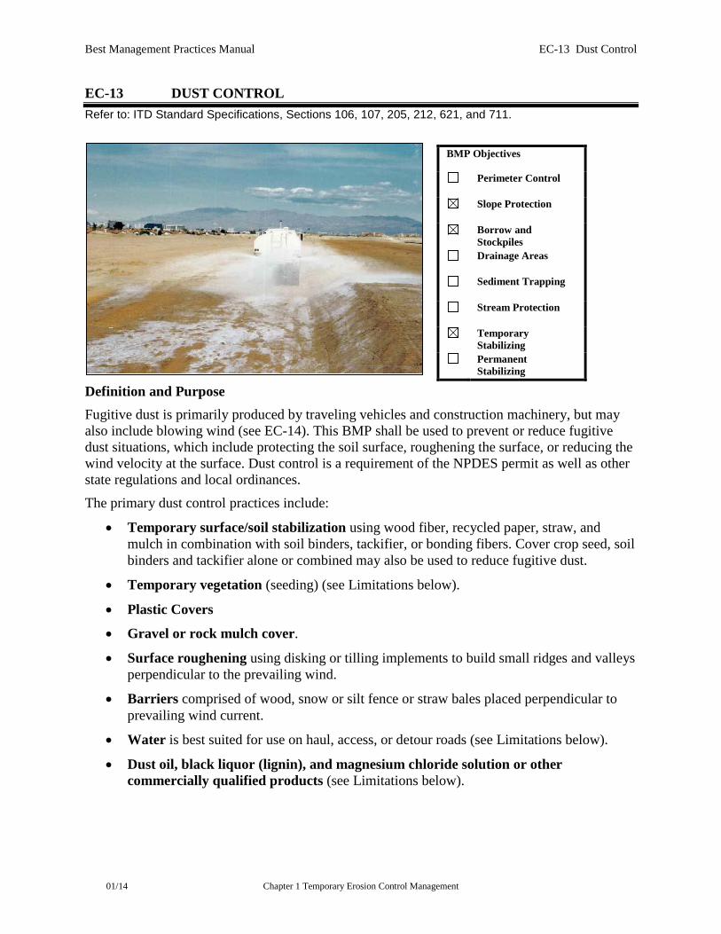
Best Management Practices Manual EC-13 Dust Control
01/14 Chapter 1 Temporary Erosion Control Management
EC-13 DUST CONTROL Refer to: ITD Standard Specifications, Sections 106, 107, 205, 212, 621, and 711.
Definition and Purpose Fugitive dust is primarily produced by traveling vehicles and construction machinery, but may also include blowing wind (see EC-14). This BMP shall be used to prevent or reduce fugitive dust situations, which include protecting the soil surface, roughening the surface, or reducing the wind velocity at the surface. Dust control is a requirement of the NPDES permit as well as other state regulations and local ordinances.
The primary dust control practices include:
• Temporary surface/soil stabilization using wood fiber, recycled paper, straw, and mulch in combination with soil binders, tackifier, or bonding fibers. Cover crop seed, soil binders and tackifier alone or combined may also be used to reduce fugitive dust.
• Temporary vegetation (seeding) (see Limitations below).
• Plastic Covers
• Gravel or rock mulch cover.
• Surface roughening using disking or tilling implements to build small ridges and valleys perpendicular to the prevailing wind.
• Barriers comprised of wood, snow or silt fence or straw bales placed perpendicular to prevailing wind current.
• Water is best suited for use on haul, access, or detour roads (see Limitations below).
• Dust oil, black liquor (lignin), and magnesium chloride solution or other commercially qualified products (see Limitations below).
BMP Objectives
Perimeter Control
Slope Protection
Borrow and Stockpiles
Drainage Areas
Sediment Trapping
Stream Protection
Temporary Stabilizing
Permanent Stabilizing
Best Management Practices Manual EC-13 Dust Control
01/14 Chapter 1 Temporary Erosion Control Management
Appropriate Applications
• The time and extent of dust control varies greatly and depends on the season, site characteristics, and area within the state. Dust abatement should be a consideration in the initial application.
• Clearing and grading activities create disturbed areas, which may require dust control measures. This includes stockpiles and/or on-site and off-site material source, waste, and storage areas.
• As a standard practice, all exposed areas should be stabilized as required by the NPDES permit. Surface erosion control measures for stormwater can also prevent erosion due to wind.
Limitations
• Water for dust abatement is very effective temporarily but can be costly long-term.
• Barriers, such as fences, may require removal and replacement several times during a construction project and may not be effective.
• Chemicals such as black liquor or magnesium chloride and oils sold for dust control may be detrimental to adjacent vegetation and soils for revegetative purposes and may adversely affect runoff.
• Temporary vegetation (seeding) alone is not practical in arid or semi-arid areas of the state unless establishment water is used. Temporary vegetation should only be considered in combination with other dust abatement measures.
• Chemicals used for dust control may require approval by ITD, EPA, and the Idaho Department of Environmental Quality.
• Commercial products not on ITD’s Qualified Products List (QPL) shall be coordinated with and approved by the Product Review Committee.
Design Parameters
• The best method for controlling fugitive dust is to prevent the movement of dust. Measures to accomplish dust control can be:
Limiting the amount of bare soil exposed at any one time through sequencing.
Locating haul, access, detour roads, and staging areas to minimize exposure.
• When designing the project, consider the most effective method or methods for dust abatement. Refer to other erosion and sediment control BMPs.
• The best method for controlling fugitive dust is to prevent the movement of dust. The Contractor shall assess potential problems and fugitive dust generation at the project site by considering the type of exposed soil, amount and type of equipment used, prevailing wind direction and the effect of other specified erosion and sediment control measures may cause.
• Provide dust control on haul, access, detour roads, and staging areas. Check that chemicals used for dust control are not detrimental to adjacent vegetation. Apply
Best Management Practices Manual EC-13 Dust Control
01/14 Chapter 1 Temporary Erosion Control Management
protective surface measures as soon as possible to minimize wind erosion. Sequence or schedule work to reduce exposed areas subject to wind erosion. Avoid over-application of water for dust abatement.
• Make field adjustments as necessary to provide for effective wind erosion control measures.
Qualified Products List Criteria See EC-8 (Soil Binders).
Maintenance and Inspection
• Inspections shall be conducted as required by the NPDES permit or contract specifications.
• Dust control requires constant attention and should be done quickly and effectively when conditions require. If control measures are applied, check at regular intervals.
• Accumulated sediment shall be removed from the barrier and disposed in an approved location.
• Chemical applications, if approved, shall be applied at the manufacturer’s recommendations and intervals.
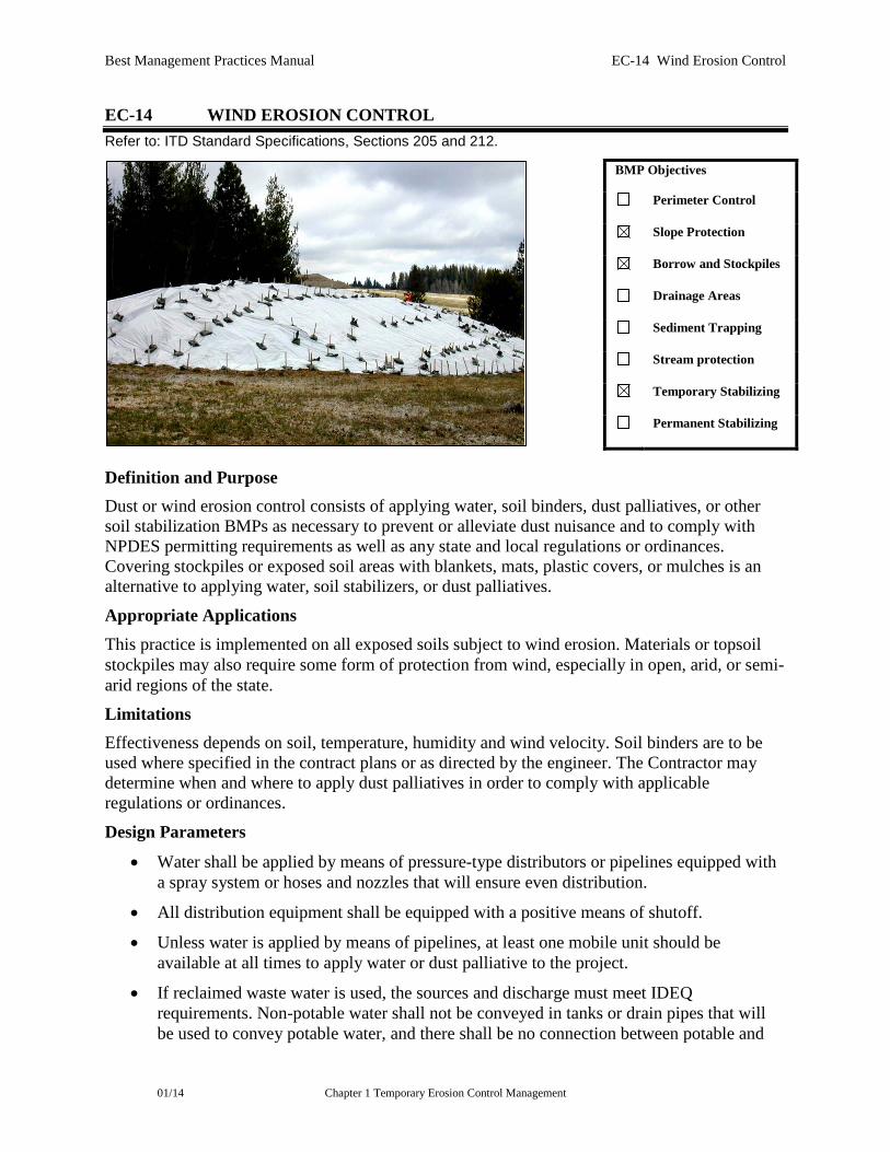
Best Management Practices Manual EC-14 Wind Erosion Control
01/14 Chapter 1 Temporary Erosion Control Management
EC-14 WIND EROSION CONTROL Refer to: ITD Standard Specifications, Sections 205 and 212.
Definition and Purpose Dust or wind erosion control consists of applying water, soil binders, dust palliatives, or other soil stabilization BMPs as necessary to prevent or alleviate dust nuisance and to comply with NPDES permitting requirements as well as any state and local regulations or ordinances. Covering stockpiles or exposed soil areas with blankets, mats, plastic covers, or mulches is an alternative to applying water, soil stabilizers, or dust palliatives.
Appropriate Applications This practice is implemented on all exposed soils subject to wind erosion. Materials or topsoil stockpiles may also require some form of protection from wind, especially in open, arid, or semi-arid regions of the state.
Limitations Effectiveness depends on soil, temperature, humidity and wind velocity. Soil binders are to be used where specified in the contract plans or as directed by the engineer. The Contractor may determine when and where to apply dust palliatives in order to comply with applicable regulations or ordinances.
Design Parameters
• Water shall be applied by means of pressure-type distributors or pipelines equipped with a spray system or hoses and nozzles that will ensure even distribution.
• All distribution equipment shall be equipped with a positive means of shutoff.
• Unless water is applied by means of pipelines, at least one mobile unit should be available at all times to apply water or dust palliative to the project.
• If reclaimed waste water is used, the sources and discharge must meet IDEQ requirements. Non-potable water shall not be conveyed in tanks or drain pipes that will be used to convey potable water, and there shall be no connection between potable and
BMP Objectives
Perimeter Control
Slope Protection
Borrow and Stockpiles
Drainage Areas
Sediment Trapping
Stream protection
Temporary Stabilizing
Permanent Stabilizing

Best Management Practices Manual EC-14 Wind Erosion Control
01/14 Chapter 1 Temporary Erosion Control Management
non-potable supplies. Non-potable tanks, pipes, and other conveyances shall be marked “NON-POTABLE WATER - DO NOT DRINK.”
• Materials applied as temporary soil binders will also provide wind erosion control benefits.
• Application of dust palliatives are subject to sample collection and testing for compliance with applicable regulations of the Idaho Administrative Code.
Qualified Products List Criteria See EC-8 (Soil Binders).
Maintenance and Inspection Conduct inspections as required by the NPDES permit or contract specifications.

Best Management Practices Manual EC-15 Snow Management
01/14 Chapter 1 Temporary Erosion Control Management
EC-15 SNOW MANAGEMENT
Definition and Purpose Snow management involves the location or relocation of snow by transporting, plowing, dozing, and/or blowing snow to locations where erosion and runoff impacts are less likely to occur during the melting process. This BMP can be used in conjunction with snow fences.
Appropriate Applications This BMP is appropriate when construction projects extend through winter months and at locations (such as high mountain areas) where snow accumulation can be significant.
Limitations This BMP may not be appropriate in areas with little snow accumulations and where access is limited.
Design Parameters
• Utilize snow blowers, snowplows, or other equipment to remove snow or move snow to less erosion-sensitive areas with proper drainage.
• Modify existing snowplow operations so snow is not piled in erosion-sensitive areas.
• Remove heavy snow accumulations from around temporary structures such as culverts to minimize ice jamming and structure failure during freeze-thaw cycles.
• Place snow in areas where soil/cover is temporary or permanently stabilized and snowmelt will have a less significant impact. Ensure appropriate controls are in place to handle snow-melt runoff.
• For projects with NPDES CGP coverage, account for snow management in the project SWPPP if the project will extend into or through winter months.
BMP Objectives
Perimeter Control
Slope Protection
Borrow and Stockpiles
Drainage Areas
Sediment Trapping
Stream Protection
Temporary Stabilizing
Permanent Stabilizing

Best Management Practices Manual EC-15 Snow Management
01/14 Chapter 1 Temporary Erosion Control Management
Maintenance and Inspection
• Conduct inspections as required by the NPDES permit or contract specifications.
• Remove or move snow as needed to reduce melt impacts.