chapter 10 psychophysics of night vision device halos
TRANSCRIPT
123
Abstract In modern Night Vision Devices (NVDs) ‘halo’ around bright light sources remains a salient imaging artifact. Although a common feature of image intensified imagery, little is known of the perceptual and operational effects of this device limitation. This paper describes two related sets of experiments. In the first set of experiments, we provide quantitative measurements of Night Vision Device (NVD) halos formed by light sources as a function of intensity and dis-tance. This characterization allows for analysis of the possible effects of halo on human perception through NVDs. In the second set of experiments, the effects of halation on the perception of depth and environmental layout are investigated psychophysically. The custom simulation environment used and results from psychophysical experiments designed to analyze halo-induced errors in slope estimation are presented. Accurate simulation of image intensifier physics and NVD scene modeling is challenging and computationally demanding, yet needs to be performed in real-time at high frame rates and at high-resolution in advanced military simulators. Given the constraints of the real-time simulation, it is impor-tant to understand how NVD artifacts impact task performance in order to make rational engineering decisions about the required level of fidelity of the NVD simulation. A salient artifact of NVD viewing is halo, the phenomenon where the image of a bright light source appears surrounded by disc-like halo. High-fidelity physical modeling of these halo phenomena would be computationally expensive.
R.S. Allison (*), T. Brandwood, M. Vinnikov, and J.E. Zacher Centre for Vision Research, York University, Toronto, ON, Canada M3J 1P3 e-mail: [email protected]
S. Jennings and T. Macuda Institute for Aerospace Research, National Research Council of Canada, Ottawa, Ontario, Canada
P. Thomas Topaz Technologies, Toronto, ON, Canada M4C 2R2
S.A. Palmisano School of Psychology, University of Wollongong, Wollongong, NSW, Australia
Chapter 10Psychophysics of Night Vision Device Halos
Robert S. Allison, Tracey Brandwood, Margarita Vinnikov, James E. Zacher, Sion Jennings, Todd Macuda, Paul Thomas, and Stephen A. Palmisano
K.K. Niall (ed.), Vision and Displays for Military and Security Applications: The Advanced Deployable Day/Night Simulation Project,DOI 10.1007/978-1-4419-1723-2_10, © Springer Science + Business Media, LLC 2010

124 R.S. Allison et al.
To evaluate the level of approximation that would be sufficient for training purposes human factors data is required.
NVD halos generated by light sources in a scene have a size that is approxi-mately invariant with intensity and distance. Objective and subjective measures of halo geometry indicate that halo size, when halo is present, is relatively invariant of target distance or intensity. This property results in perceptual distortions and strong illusions with isolated stimuli. In complex scenes, systematic distortions of slant are predicted due to an imposed texture gradient created by the halo. We investigated this hypothesis in psychophysical experiments. The results suggest that perception of slant and glideslope in complex scenes is remarkably tolerant of texture gradients imposed by NVG halo. These results are discussed in terms of NVG simulation and of the ability of human operators to compensate for percep-tual distortions.
Sommaire Effectuer des mesures quantitatives des halos autour des sources lumineuses perçus par les dispositifs de vision de nuit (DVN) selon l’intensité et la distance, décrire une méthode visant à simuler leurs effets en laboratoire et présenter les résultats des expériences psychophysiques ayant pour but d’analyser les erreurs induites par les halos dans l’estimation de la pente. Simuler avec préci-sion la physique des intensificateurs d’images et modéliser les scènes observées à l’aide des DVN est difficile et exige beaucoup de calculs, or il faut réaliser ces activités en temps réel avec une fréquence d’images et une résolution élevées dans des simulateurs militaires de pointe. Étant donné les limites inhérentes à la simula-tion en temps réel, il est important de comprendre les incidences des artéfacts des DVN sur l’exécution des tâches afin de prendre des décisions rationnelles tech-niques sur le niveau de fidélité requis. La présence d’un halo ayant la forme d’un disque autour des sources lumineuses est un artéfact propre aux DVN.
Lorsque les repères indiquaient de façon évidente que la scène observée était inclinée, les participants ont perçu une pente proche de celle que l’on trouvait en l’absence de halo, tel que prévu. L’agencement régulier des lumières a permis d’obtenir différentes perspectives de profondeur, y compris la perspective linéaire, les gradients de texture, la compression (et l’effet de rapprochement) et la possi-bilité d’inférer un horizon implicite. Lorsque des halos sont présents dans une scène et qu’ils sont associés à une surface inclinée, leur grandeur varie, dans une cer-taine mesure, avec la distance apparente (constance de la grandeur). Il n’y a que peu de conflit dans ce cas particulier, étant donné que les repères de pente dominent et que l’invariance du halo est perçue comme un gradient de taille. Nous examinerons les résultats de la simulation NVG et la capacité de l’utilisateur à compenser les distorsions liées à la perception.
Night vision devices (NVD or Night Vision Goggles, NVGs) are critical to night operations for military aviators and ground forces. The devices allow forces to ‘own the night’ by intensifying ambient illumination, providing visibility under

12510 Psychophysics of Night Vision Device Halos
reduced light conditions. However image intensifiers do not provide daytime equivalent vision and the devices suffer from a number of limitations or artefacts. For example, the image is monochromatic, contaminated by image noise at low light levels, the unusual spectral sensitivity can result in contrast inversions and field of view is limited in most devices. These limitations and artefacts presumably underlie the reported deficits in perception of space, depth and motion (for exam-ple Berkley 1992; Bradley and Kaiser 1994; Braithwaite et al., 1998; DeLucia and Task 1995; DeVilbiss et al. 1994; Geri et al. 2002; Hughes et al. 2000; Jennings and Craig 2000; Knight et al., 1998; Macuda et al. 2004; Niall et al. 1999; Rabin and Wiley 1994; Sheehy and Wilkinson 1989; Task 2001).
In high-fidelity simulation these limitations require special attention for a number of reasons. First, limits on operator perception and performance need to be simu-lated; any deficits in simulation fidelity need to be understood and quantified to allow an appropriate test of the perceptual capabilities required in a given situation. Second, accurate simulation of NVD characteristics can allow trainers to highlight and illustrate artefacts or limitations of the devices. Third, device limitations can influence operational procedures, which in turn may need to be rehearsed and simulated. While accurate simulation of image intensifier physics and NVD scene modeling is extremely challenging and computationally demanding, it needs to be performed in real-time at high frame rates, and at high-resolution in advanced mili-tary simulators. Given the constraints of the real-time simulation it is important to understand the nature of NVD artefacts and how they impact task performance in order to make rational engineering decisions about the level of fidelity required and level of implementation effort to commit to modeling the device.
One salient artefact of NVD viewing is halo. Halo in the context of NVDs refers to the phenomenon that a bright light source viewed through NVDs appears to be surrounded by a corona or halo that is much larger than predicted by the point spread function of the device. If a bright light, such as a NVD incompatible vehicle light, is viewed then the user typically reports seeing the image of the light source surrounded by disc-like halo. The brightness of the disc depends on the intensity of the light source and can appear transparent for relatively weak lights allowing for visibility of scenery beyond the halo. Examination of these halos is important for NVD simulation and to understand limitations on their use in operational settings (as well as to develop and train compensatory strategies).
While there have been many anecdotal reports and descriptions of the phenom-enology and effects of NVD halo, published data in the open literature is sparse. Metrics such as halo intensity, transparency, symmetry, and profile shape and their dependence on source intensity, distance, shape and spectral characteristics are important, but relatively unexplored in the open literature (Craig et al. 2005; Thomas et al. 2005). With current technology, halo is a ubiquitous feature of both the built environment and natural scenes (e.g. the stars in the night sky). The phenomenon is superficially similar to the physiological halo reported in normal and diseased eyes and the coronas seen when viewing light sources through the atmosphere. However the presence of halos around numerous light sources is both an unusual and unnatural stimulus.

126 R.S. Allison et al.
The effective brightness of the image of a light source depends on intensity, direction and spectral content. Informally, we have noted that halo angular size in the image is largely independent of source intensity and distance. Once a light is bright enough then a halo will appear. Increasing the intensity of this light increases the brightness of the ‘disc’ and diminishes its transparency. However, the halos of both very bright and moderately bright light sources will have the same angular diameter. With very bright sources the primary halo appears to be surrounded by a weaker secondary halo. NVD images may have other artefacts created by bright light sources (e.g. lens flare) and care must be taken not to confuse these with halo. Halos of nearby or extended sources can merge and form extended halos surround-ing the extended configuration. NVD halos are generated in the image intensifier tubes. Being device artefacts, they have characteristics that are significantly differ-ent from the associated environmental features in the image. These distinctions are important and predict specific distortions of perceived environmental layout and movement. We provide quantitative psychophysical and objective descriptions of the halos formed by light sources as a function of intensity and distance and report psychophysical experiments designed to analyze halo-induced errors in estimates of slope and aimpoint.
10.1 Variation in Halo Size with Source Distance and Intensity
Evaluation of the perceptual effects of halo depends on an understanding of their image characteristics. We designed a study to compare perceptual and objective measures of NVD halo size directly using identical laboratory conditions.
10.2 Methods
A custom built light source and optical bench were designed and built to present vari-able intensity stimuli at a range of distances. The observer’s head was supported in a head and chin rest and placed in front of the NVD eye piece. The NVD was a standard ANVIS-9 with GenIII image intensifier tubes. The target light source was an LED mounted in a custom housing and driven by a custom driver board under computer control. A small 0.5 mm aperture was mounted at the output of the LED source to ensure the target could be regarded as a point source. Driving the LED with a pulse-width modulated digital signal permitted a wide range of light source intensity. The PWM frequency (1,000 Hz) was sufficient such that no flicker was observed.
In separate blocks of trials the target light was presented at one of three distances from the nodal point of the NVD objective (2, 4 and 8 m) at approximately the centre of the NVD field of view. At each distance the target was presented at one of five intensity levels scaled for viewing distance. The target was either presented in darkness (the room was blackened, extraneous light baffled and suppressed with

12710 Psychophysics of Night Vision Device Halos
matte black cloth, paint or paper) or in the presence of an illuminated surround. The illuminated surround filled the periphery of the NVD field of view but did not illu-minate the target. A gap of 10–15° was placed between the edge of the surround and the target. The purpose of the surround was to study the effect of the NVD automatic gain control (AGC) on halo size. Thus there were 30 different conditions (3 distances × 5 intensity levels × 2 background illumination conditions). These conditions were repeated five times per observer resulting in 150 measurements per observer within a counterbalanced design to control for any order effects.
For each condition we made three measurements in separate trials. Two mea-surements were subjective and intended to measure apparent halo angular size (image size as opposed to linear size in the world) and the third was an objective measure using a digital camera. All measures were cross calibrated to each other and to standard targets at known distances to get commensurable data in terms of visual angle at the NVD.
The first subjective measurement was direct and used a fine-grained reticule mounted in the NVD eyepiece as a gauge. The 18 mm reticule had horizontal and vertical scales extending 5 mm from the centre that were marked in steps of 5 mm per minor division with major divisions marked and enumerated every ten steps. The cross hair formed by the intersection of the axis was centred on the target and the observer was required to estimate the radius of the halo in terms of the number of divisions covered.
The second subjective measurement used an approach similar to a linear stage micrometer. A long-travel, motorized linear translation stage was mounted with its direction of travel perpendicular to the viewing direction just in front of the light source (fixed together on a rigid plate that could be moved between the viewing distances). Mounted to the stage was a long, vertically oriented illuminated line (formed by LEDs) that could be translated horizontally in front of the target. Care was taken that the line did not produce a halo. At the beginning of each trial the line was aligned visually with the halo-producing target. Then the observer moved the stage outward until the inside edge of the illuminated line of the stage micrometer was aligned with the perceived edge of the halo (a precise Vernier alignment task). The stage was moved with a stepper motor and an encoder was used to measure the stage position with a resolution of 2,048 counts per cm of translation. The measure-ments were repeated starting well outside the halo region to account for hysteresis effects. The halo diameter was estimated by comparing the distance between the indicated left and right edges of the halo.
For the objective measurements, a Nikon Coolpix 5400 digital camera was placed in the position of the observer’s eye and used to image the NVD output through the ocular. The camera is based on a 2,592 × 1,944 pixel colour CCD sensor. The camera was set to manual focus within the shutter priority control mode and a short focal length was chosen from the camera range of 5.8–24 mm (35 mm equivalents 28–116 mm). The camera was shrouded to prevent light contamination. Five LED intensities were chosen for each distance to provide overlap in equivalent intensity ranges between distances and to produce a wide variety of halos (none, single, and double).

128 R.S. Allison et al.
10.3 Objective Measures
Examples of images captured by the digital imager are shown in Fig. 10.1. Typically as light intensity increased the image changed from showing a small spot to having an obvious halo to showing signs of double halos. To estimate the halo widths the centre of mass of the image of the light source was calculated. Then cross-sections at 1° intervals were made through the centre of the spot and averaged to reduce noise (see Fig. 10.1). Estimates of the half-width of the principal halo were based on the distance between maxima in change in slope in these cross-sections and plotted in Fig. 10.2 as a function of intensity for both the background and no background conditions.
In can be seen that halo size is approximately 1.7° when halo is present and that there is no consistent variation in intensity despite a fourfold variation in distance and a 1,000-fold change in intensity. Small estimates at the lowest intensity corre-spond to situations where a primary halo could not be detected in the image. Moving a real object from 8 m to 2 m would have resulted in a fourfold increase in image size whereas halo size does not vary with distance.
10.4 Subjective Measures
Both the reticule and halo measures were consistent with the objective data and indicated a perceived halo of roughly 1.7° of visual angle (Fig. 10.2). Responses at 2 m were slightly smaller than at 4 and 8 m but this reduction was less than 5%.
00
0.2
0.4
0.6
0.8
1
Position (°)
Rel
ativ
e In
tens
ity
0.5−0.5−1−1.5 1 1.5
Fig. 10.1 Typical halo imagery for two intensities. On the upper left, the bright central spot is centered on the point source target and a ‘disc’ halo surrounds the spot. A secondary halo is more pronounced in the lower image. Dynamic range limitations of the camera are apparent in the satu-ration of the bright central spot. The apparent whitening and widening of the central spot in very bright halos is not apparent when viewing by eye. The right-hand plot shows a cross-section

12910 Psychophysics of Night Vision Device Halos
More data would be required to determine if this effect was reliable and if it was perceptual in origin. Background lighting drove the AGC of the NVD effectively. Observers were less likely to perceive single or double halos with the background light than without at any given intensity. However, the background light did not appear to have a significant effect on the halo size. Halo estimates were variable with the AGC engaged and the observers reported that the halo edge was less dis-tinct and the judgements more difficult.
10.5 Discussion
If a point source is bright enough to generate a halo then the size (but not intensity or transparency) of that halo is effectively constant over changes in distance and intensity – at least until secondary halos are seen. Any change in apparent size is small compared to the more salient effects of halo disappearance or double halo appearance as the source intensity is decreased or increased respectively (we assume that the principal effect of distance is on effective intensity). Halo intensity profile falls with eccentricity from the centre of the spot but is remarkably flat over the ‘disc’ potion of the halo. This effect needs to be modeled precisely but provides justification for our simple disc model of halo in the psychophysical experiments.
How do scene characteristics affect the physical (as opposed to perceptual) halos generated by NVDs? Presumably, the principal parameter controlling halo generation
Fig. 10.2 Estimated halo width as a function of intensity

130 R.S. Allison et al.
is effective source intensity. This allows us to generalize to larger distances and to natural scenes. Typically the device is focused at a far distance (i.e. optical infinity) and depth of field is not an issue beyond a few meters. If the distance is large enough that the target is effectively a point source within the device’s depth of field, then distance cannot be a determinant of halo size per se beyond its effect on effec-tive source intensity. Similarly, the effective intensity of a source depends on its spectral characteristics and the wavelength selectivity of the NVD photocathode. Finally, the effective intensity is also a function of the ‘gain’ of the NVD, which is determined by scene illumination. As discussed above, the source intensity affects the likelihood that a primary and secondary halo will be perceived and the vividness of the halo but has little effect on halo image size when halo is present.
10.6 Halos as Visual Stimuli
The fact that primary halos do not change their angular size as a function of the distance of their generating sources lends them interesting perceptual properties. The image size of a real object is determined by its egocentric distance according to the laws of perspective projection. However, halos are generated in the sensor and are therefore similar to the afterimages seen when closing one’s eyes after viewing a bright light, which have a fixed retinal size. If one then gazes around an environment, an afterimage will appear to change size depending on the distance of the surface on to which it is projected. ‘Emmert’s law’ describes how the apparent linear size of an afterimage depends on its perceived distance (Emmert 1881). Since halos also have a fixed retinal image size, Emmert’s law predicts that their apparent linear size will: (a) grow as their perceived distance from the observer increases; and (b) shrink as their perceived distance decreases. Brightness is also a cue to distance and an isolated bright halo should appear nearer than a dim one even if further away. We have verified these predictions in the lab. It is important to note that complete size constancy is not to be expected and size constancy is reportedly poorer in NVD imagery than natural viewing (Zalevski et al. 2000).
When approaching a landing zone in a helicopter, a pilot must make judgements about the suitability of the terrain and their current approach. Similarly in terrain following or nap-of-the-earth flight pilots must make continuous judgements of the layout and respond accordingly. Besides affecting judgements of their depth and size, halos could have affects on the perception of the layout of the environment and surfaces within it as well as one’s movement through it. Judgements of surface slant (and tilt) can be used to estimate the orientation and layout of surfaces in the envi-ronment and provide critical information during helicopter low-level flight and landing. When making judgements of slant, humans rely on a number of visual cues including perspective, binocular disparity and motion parallax.
One perspective-based cue that humans could use is known as texture gradient. If a homogeneously textured flat surface (such as a ground plane) is slanted in depth, then its retinal image will contain a gradient of texture element image size

13110 Psychophysics of Night Vision Device Halos
from near to far (Cutting and Millard 1984). This gradient will be manifest in the size of texture elements, their spacing, foreshortening and their density and will be present in NVD imagery. In the case of NVD halos, patterns of lights on the ground have an added texture corresponding to the halos generated by the NVD tubes. However, as halo size (and shape) is not related to source distance, this will be in conflict with perspective-based information in the scene.
When aircraft position or orientation changes with respect to the environment, additional cues are available within the dynamic retinal image that can indicate surface slant and the motion of the observer with respect to the environment. Judgement and control of the glideslope is a critical flight task. During approach, the stream of retinal images contains changing perspective and optic flow that could be used to determine the glideslope. During an NVD approach, the perspective change in the location of objects in the optic array is consistent with the observer’s self-motion (global optic flow), but the lack of local optical expansion/contraction of their halos is not. Thus, we might expect that glideslope estimation to be impaired when other cues to self-motion and environmental layout are weak.
10.7 Simulation Environment
In order to assess the effects of halo and other artefacts we have implemented a simulation environment for NVD human factors experiments. Three-dimensional computer graphic simulation of flight over modeled terrain was rendered by a clus-ter of Linux-based PC workstations. Scenes were modeled in 3D Studio Max based on digital terrain maps. We used an in-house developed virtual environment API (VE 2.2) to control and configure the simulation, display and input devices. The simulation was primarily visual and aircraft dynamics were not modeled. However, the simulation gave considerable flexibility for inclusion of various artefacts and for script based experimental sequencing. Extensive use of state-of-the art shader language techniques allowed real-time generation of the modeled NVD halo. The program was designed to allow for implementation of a flexible halo model. While various physical models can be implemented, halos were initially modeled as disks subtending a constant visual angle. The experiments were conducted in a large format stereoscopic virtual immersive environment. Mirrors mounted at ±45° were located in front of the left/right eyes so that each eye viewed a large projection screen located to the side. Images were projected onto the screens via BARCO 808 projectors (Barco N.V., Belgium) with a resolution of 1,280 × 1,024 × 100 Hz. Each screen was driven by a separate graphics workstation in a Linux based graphics cluster. The video cards (NVidia Quadro FX 3000G, NVidia Corp. Santa Clara CA) for the displays were genlocked and the simulations synchronized.
Simulated helicopter approaches to a runway were rendered with imposed NVD effects from a physics-based model (only monochromatic display and halos were modeled). The modeled world contained a large flat plateau with a landing strip in the centre. The plateau was surrounded by simulated mountains that were unpredictable

132 R.S. Allison et al.
in location, height and distance on the plateau to prevent their being used as reliable visual cues.
Stereoscopic images of simplified night scenes were rendered with halo or non-halo inducing light sources distributed on the ground plane. The intrinsic texture and perspective cues to depth in the scenes were varied by changing the regularity and configuration of the light sources. The regular lighting was com-posed of a runway lighting pattern based on a Precision Approach Category I lighting system (Transport Canada 1993, pp.5–25) with 282 lights arranged in a runway pattern. There was a rectilinear set of lights on the approach path, a hori-zontally extended set of lights marking the threshold and two rows of lights out-lining the runway beyond the threshold (Fig. 10.3). The runway was 53 m wide by 1,850 m long and surrounded by gray tarmac that was visible in the daylight condition. For the irregular pattern of lights, the runway lights were randomly redistributed on the ground throughout a bounding box that bounded the regular landing light pattern.
10.8 Halo Effects and Slope Judgements
The effects of halo on judgments of slope were studied during simulated level-flight helicopter flight. The halo size estimation data allowed us to predict expected effects on texture gradients in the scene. We modeled halo image size as invariant with distance, which is true to first-order in both our objective and perceptual halo measures. Thus, the similar/identical relative sizes of these halos suggested that the observer was viewing a frontal surface. However, this interpretation was inconsis-tent with the information provided by the other depth cues in the display, including binocular disparity, motion parallax, texture gradients of light position and light density gradients. These latter cues will of course scale image size with depth
Fig. 10.3 Screen shots from simulated approaches. The light on the left is isolated for illustrative purposes. The frame rate indication was turned off for the experiment and was half the video refresh rate

13310 Psychophysics of Night Vision Device Halos
according to the laws of perspective. We expected that the effects of such cue conflicts on slant judgements would be most pronounced when veridical cues were weak and minimal when strong cues to slant from texture, motion and binocular disparity exist. Conversely, we expected that when surface slant was correctly per-ceived, the halo would be interpreted as a feature in the environment. In the following experiment we investigated the effects of superimposed halo on slant percepts when the surface was defined by regular or irregular patterns of lights and under static or dynamic conditions.
10.9 Methods
In these experiments, observers made judgments about their attitude with respect to the ground. During the simulation the observers were set at a slant with respect to the ground (via virtual camera pitch) and were required to make judg-ments of surface orientation in depth. The lighting pattern and halo were con-trolled as described above (Simulation Environment). The test scenes were either static, or depicted simulated lateral motion, or a simulated level flight approach. Observers were instructed to estimate the slope, in pitch, of the air-craft (the virtual camera) with respect to the ground (or equivalently the slope of the ground with respect to the virtual camera). Following the stimulus a fully-lit, full-cue daylight scene was displayed with random pitch angle. The observers were given control of the pitch of the virtual camera and were asked to match the attitude of the virtual camera to their estimate. The match setting was recorded and the next trial began.
To ensure that observers could perform the matching task reliably they were pre-trained. Observers trained on this task by estimating a large range of surface slants presented in full-cue daylight conditions. We reasoned that this condition would give the most reliable slant percepts and the best estimates of measure-ment error in the matching method. Following each presentation of the training stimulus subjects made two match settings. Observers received feedback indicating the sign of their error after their initial setting to maximize their performance. They were requested to make second setting and were not provided feedback on this setting. Pre-training was continued until the response variance reached accept-able levels and was stable. All observers required two training sessions to reach this level of performance. There was a minimum period of 24 h between training sessions.
The following manipulations were made in a factorial, repeated measures experiment: approach type (forward, lateral, static), aircraft pitch angle (−10º, −5º, 0º, 5º, 10º), light pattern (regular vs. irregular), and lighting condition (day, night no halo, night with halo). The sequence began with the aircraft positioned 53 m above ground level (172¢ AGL) at a distance of 431.5 m from the end of the runway. Velocity during dynamic conditions was 10 m/s. The stimulus duration for all con-ditions was 5 s.

134 R.S. Allison et al.
10.10 Results
All observers required two training sessions. Training was rapid and all observers could reliably indicate a full-cue slant within the criterion set (R2 > 0.85 with a slope coefficient greater than 0.80). A multivariate repeated-measures analysis of variance (MANOVA) demonstrated that there was no significant effect of type of approach (F(1,5) = 3.14, p = 0.127). Mean slant estimates are shown in Fig. 10.4. Subjects perceived increasing slant with increasing simulated slant in the daylight conditions and in night-time conditions with regular patterns of lights in the absence of halo (R2 = 0.77, F(1, 59) = 191.84, p < 0.001 and R2 = 0.69, F(1, 59) = 257.14, p < 0.001, respectively). There was no significant difference between the slopes estimated in daylight and night-time conditions. In all conditions the slant was underestimated and tended toward zero. In the presence of halo this underestimation was much more pronounced and slant estimates were small and not significantly related to the portrayed slant. Irregular patterns of lights resulted in a poor correlation between perceived and simulated slant. The pattern of slant estimates as a function of simulated slant under halo for regular lights was similar to that seen in all night-time irregular lighting conditions.
When slant was seen in the regular light arrangement and halos were present, observers reported a strong impression of an increase in the perceived size of the halos with simulated distance even though the halo image size was constant across the image. This was size constancy consistent with Emmert’s law. Anecdotally observers reported that in these conditions they could ‘see through’ the halo to the slanted surface, which suggested that they could segregate the slant of the surface from the frontal slant specified by the halo.
Fig. 10.4 Slant estimates as a function of simulated slant for the halo and lighting combinations averaged across six observers (mean ± s.e.m. plotted). Left hand panel shows the effects of halo on slope estimation for the structured lighting (runway lights). The right hand panel shows estimates for the random lighting condition
13510 Psychophysics of Night Vision Device Halos
10.11 Discussion
The regular pattern of lights provided a variety of perspective cues to depth including linear perspective, texture gradients, compression (and foreshortening) and the pos-sibility of inferring an implicit horizon. When halos are present in a scene and associ-ated with a slanted surface, their size scales with apparent distance at least to an extent (size constancy). There is little conflict here as the strong slant cues dominate and the halo invariance is seen as a size gradient. In the daylight or at night when slant cues in the scene were strong (due to a regular light pattern and absence of halo), observers perceived slant that was near the simulated slant as predicted. However, even under these conditions matched slant generally fell short of simulated slant. Gibson (1950) reported that observers consistently underestimate the slant of surfaces defined by a texture gradient in the absence of other cues. He noted that this regression to the frontal plane was much stronger for irregular textures than for regular textures. Here we have a similar finding where slant was underestimated in all cases, except that the regression was to the level ground plane rather than the frontal plane. It is likely then that either the level ground plane or the frontal plane can act as a ‘norm’ for slant judgements. In Bayesian terms the ‘norm’ would reflect a ‘prior’ assumption of the visual system that favours level or frontal surfaces (e.g. Knill 1998; Knill and Saunders 2003). Whether the frontal plane or level ground is preferred in Gibson’s regression to the norm likely depends on the viewing situation.
This observed tendency to underestimate slant was exaggerated when we used an irregular (as opposed to regular) pattern of lights at night. With this irregular pattern, slant percepts were markedly reduced in both halo and non-halo conditions. One effect of texture irregularity is to add noise to estimates of texture gradient. Young et al. (1993) have provided evidence that under cue conflict, percepts shift to the more reliable cue (or toward a norm) when noise degrades information from the other. The current results suggest that the irregular pattern of lights provided significantly less reliable slant information than the regular pattern. We had hypoth-esized that changing perspective due to motion would provide particularly com-pelling slant information because stronger assumptions could be made than in the static case even with irregular lights (Allison and Howard 2000). However, perceived slant was as weak under dynamic conditions as under static conditions, indicating that motion was not able to compensate for the lack of regularity in the lighting pattern.
We had hypothesized a strong effect of adding halo under irregular lighting con-ditions. We reasoned that gradient of halo size, which was consistent with a frontal surface, should have dominated when the cues indicating the simulated slant of the ground were weakened by the use of irregular textures. However, the irregular tex-ture manipulation may have been too strong, removing any reliable percept of sur-face slant change thus preventing any possibility of a halo effect (a floor effect).
In contrast, slant estimates with the regular landing light pattern at night were similar to daylight estimates and changed appropriately with changes in portrayed slant in the absence of halo. With regular light patterns, addition of halo had a

136 R.S. Allison et al.
marked effect and resulted in weak slant percepts. Interestingly, the slant did not tend toward the frontal plane (consistent with the halo size gradient) but rather toward the level ground norm. Thus, the effect of adding halo to the scene was similar to the effect of using irregular rather than regular lighting patterns. This equivalence suggests that additional of halo has an effect of degrading the percept of slant from the texture gradient. The visual system thus treats the estimate as less reliable and slant matches reflect the prior bias for level ground rather than the degraded slant from texture.
Interestingly, observers viewing natural scenes sometimes report being able to see both a frontally oriented pattern of halos and to see through it to a slanted scene. Such dual percepts are sometimes seen in cue conflict situations. Van Ee et al. (2002) have claimed that for slant perception these dual percepts are alternating and bistable (like the famous Necker cube). However, for slanted surfaces the subjective impression is usually simultaneous rather than alternating. Study of the resolution of the cue conflict created by halo in scenes that are nearer frontal (i.e. a steep hill or cliff face), so that the slants specified by the halo texture gradient (a frontal sur-face) and the true surface are more similar and thus more likely to be combined rather than bistable, may be informative.
10.12 Halo Effects and Aimpoint Estimation
In the second set of experiments, observers watched a simulated approach to the runway and estimated the aimpoint or touchdown point given their current heading. Estimation and control of glideslope and aimpoint is traditionally thought to rely on processing of optic flow and perspective based cues in the visual image (Palmisano and Gillam 2005) that could be disrupted by halo.
10.13 Methods
The simulation environment was similar to the previous experiment except that approach to a runway along a fixed glideslope was simulated. The environment, lighting patterns and lighting conditions were the same as in the previous experi-ments. For each trial, the stereoscopic simulation began with the aircraft set at an altitude of either 76 m above ground level (248¢ AGL) or 152 m AGL (495¢ AGL). The aircraft began 431 m from the end of the runway and descended toward the runway along a fixed glide slope that was varied between trials. The attitude of the aircraft was aligned so that the virtual camera pointed along the simulated glideslope. The aircraft was then translated along the glideslope at a constant for-ward velocity of 10 m/s for 5 s. The descent rate was set by the glideslope and varied from 0.53 to 1.76 m/s.

13710 Psychophysics of Night Vision Device Halos
At this point the animation stopped and a horizontally extended red line appeared across the screen drawn across the terrain at a random distances. Using buttons on a gamepad the observer adjusted the vertical screen position (i.e. perceived dis-tance) of the line so that it appeared to be aligned with/intersect their perceived future touchdown point. The scene then disappeared and the next trial began. To ensure that observers could perform the aimpoint task reliably they were pre-trained. Observers trained on this task while estimating aimpoint in full-cue day-light conditions for a large range of glideslopes (−5º to −50º). Observers made two settings for each trial. They received feedback after their initial setting. Following this, they were requested to make another aimpoint setting without feedback. This training was continued until the response variance reached acceptable levels and was stable.
The following dependent variables were varied in a factorial, repeated measures experiment: glideslope (−3º,−4º, −5º, −6º, −7º, or −8º), altitude (high or low), light pattern (regular vs. irregular), and lighting condition (day, night no halo, night with halo).
10.14 Results and Discussion
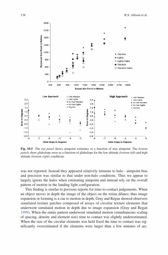
The results are shown in Fig. 10.5. There were no significant effects of lighting condition or lighting pattern. Further, there was no significant interaction between these variables and the simulated glideslope or altitude. A prominent trend for both the high and low approach conditions was that observers appeared to overestimate distances for steeper glideslopes (mean glideslope error for −8° glideslope of 0.72 and 1.31 for the low and high conditions respectively) and underestimate aimpoint distances for shallow glideslopes (mean error for −3° glideslope of −0.69 and −0.98 for the low and high conditions respectively). This was consistent with the findings of Palmisano and Gillam (2005) who found that the bias was accentuated when the simulated ground plane was covered with randomly positioned dots (compared to a grid pattern). These authors concluded that optic flow information alone was insufficient for unbiased estimation of glideslope or aimpoint and argued that the insufficient information was a source of ‘black hole illusion’ landing errors (see also Gibb 2007).
Gibson (1950) argued that we use properties of the optic flow field, such as the focus of expansion, to estimate our aimpoint in a scene. When we move relative to the environment the image projected on the optic array (a theoretical projection surface fixed to the observer) flows out and away from a focus of expansion that lies in the direction of the observer motion. Extracting the optic flow from the retinal flow is complicated with real, mobile eyes but we could estimate our direction of travel from optic flow. In the current experiment, the global pattern of optic flow was consistent with the simulated motion but the lack of expansion of the halos was not consistent with self motion through a rigid environment. Observers could have perceived this non-rigidity as object motion of the halo light sources although this
138 R.S. Allison et al.
was not reported. Instead they appeared relatively immune to halo - aimpoint bias and precision was similar to that under non-halo conditions. Thus we appear to largely ignore the halos when estimating aimpoint and instead rely on the overall pattern of motion in the landing light configuration.
This finding is similar to previous reports for time-to-contact judgements. When an object moves in depth the image of the object on the retina dilates; thus image expansion or looming is a cue to motion in depth. Gray and Regan showed observers simulated texture patches composed of arrays of circular texture elements that underwent simulated motion in depth due to image expansion (Gray and Regan 1999). When the entire pattern underwent simulated motion (simultaneous scaling of spacing, density and element size) time to contact was slightly underestimated. When the size of the circular elements was held fixed the time to contact was sig-nificantly overestimated if the elements were larger than a few minutes of arc.
Fig. 10.5 The top panel shows aimpoint estimates as a function of true aimpoint. The bottom panels show glideslope error as a function of glideslope for the low altitude (bottom left) and high altitude (bottom right) conditions

13910 Psychophysics of Night Vision Device Halos
However, the subjects still perceived the overall pattern as approaching which indicated dominance of the global expansion of the pattern. Harris and Giachritsis have shown that estimates of time to contact in optic flow displays consisting of clusters of dot patterns is based primarily on global rather than local image expansion (Giachritsis and Harris 2005; Harris and Giachritsis 2000). Interestingly, cells in the medial superior temporal area of the monkey brain, which is believed to be special-ized for processing of optic flow, are reportedly more sensitive to the overall pattern of image motion than to the size changes in texture elements (Tanaka et al. 1989).
Besides optic flow a number of other potential cues that could indicate aimpoint position on the runway. Many of these are perspective based including splay angle of the runway (related to linear perspective), depression, runway aspect ratio cues, and so on. These configural cues depend upon spatial relations between features in the scene. If these features can be picked up in the image then halo should have relatively little effect since it will affect the image of individual lights but not their spatial configuration. Thus the splay angle of the runway (Flach et al. 1997) or its aspect ratio (Galanis et al. 2001) should not be affected as long as the halos do not obscure the light positions or merge into competing features. The fact that we did not find a detrimental effect of halo is consistent these configural strategies. However, many configural strategies depend on or are enhanced by regular patterns of lights, which was not evident from our data. Interestingly, Palmisano and Gillam (2005) did find a significant effect of light arrangement but their (non-stereoscopic binocularly-viewed) patterns had visible horizons and were sparser making them more likely to show a pattern effect. Thus, further simulation testing with both regular and irregular light patterns might provide useful insights into configural strategies that are being used to perceive aimpoint during the final approach for landing.
10.15 Conclusions
Objective and subjective measures of halo geometry indicate that halo size, when halo is present, is relatively invariant of target distance or intensity. Any change in apparent size is small compared to the more salient effects of halo disappearance or double halo appearance as the source intensity is decreased or increased respec-tively. Halo intensity profile falls with eccentricity from the centre of the spot but is remarkably flat over the ‘disc’ portion of the halo. These halo characteristics predict systematic distortions of slant and glideslope due to an imposed texture gradient and interference with optic flow processing. We investigated these hypoth-eses in a series of psychophysical experiments. Halos appear to act to make slant estimates less reliable but do not cause a bias toward the frontal plane when viewing ground plane surfaces. When slant is seen and halos are present, subjects report a strong impression of an increase in the perceived size of the halos with simulated distance although halos are constant size over the image. This is appropriate size constancy as found in Emmert’s law. Anecdotally subjects report that they can ‘see

140 R.S. Allison et al.
through’ the halo to the slanted surface suggesting they can segregate the slant of the surface from the frontal slant specified by the halo. Consistent with previous work in time to contact perception there appears to be little effect of halo on per-ceived aimpoint during simulated landing. Future work could incorporate increas-ingly more realistic physical halo models and address active perception and control of glideslope during simulated landing in the presence of halo.
Acknowledgements This work was performed for the NRC Flight Research Laboratory under PWGSC Contract #561982 in support of the Advanced Deployable Day/Night Simulation Technology Demonstration Project led by DRDC Toronto. Alex Tumanov and Jason Telner assisted in data collection for preliminary experiments related to this research. Portions of this work were reported in the proceedings of the SPIE Defense and Security conference held in Orlando, FL, April 9–13, 2007.