chapter 12 pure torsion · pure torsion 12.1 generals a member is subjected to pure torsion if in...
TRANSCRIPT

Chapter 12
PURE TORSION
12.1 GENERALS
A member is subjected to pure torsion if in any cross section of this member
the single stress different from zero is the moment of torsion or twisting (shorter
TORQUE).
Pure torsion appears when exterior forces acting perpendicular to the bar axis
produce only moments of torsion acting along the bar axis (Fig.12.1).
Fig.12.1 Fig.12.2
The study of torsion is simple for elements with circular or ring-shape cross
sections, using completely the hypothesis from Mechanics of Materials. For other
types of cross sections: rectangular, sections made from laminated profiles (open
or closed), the study is more complex, using the methods from Theory of
Elasticity. This is a consequence of the fact that these cross sections are distortion
during the member twist. For circular section, due to the symmetry of solicitation,
this distortion doesn’t appear (the cross sections remain plane during the twist).
For a rectangular section the initial plane section become after twist approximately
a hyperbolic paraboloid (Fig.12.2). If the distortion is freely produced the torsion is
called free or pure. If the distortion is prevented from warping we discuss about
prevented or ununiform torsion.

12.2 TORSION OF BARS WITH CIRCULAR SECTION
Let us consider a circular bar, rectangular sheared by parallel circles and
equidistant generatrix. Due to the twisting produced by the torques Mt the
generatrix are inclined with the same angle, becoming inclined straight lines. The
circular sections remain circular during twist and the distances between them do
not change. In the rectangles from network only angular deformations γ appear
(Fig.12.3).
Fig.12.3
The cross sections remain plane after deformation and perpendicular to the
bar axis, so the Bernoulli’s hypothesis is again certified.
We isolate a differential element from bar (Fig.12.4).
Fig.12.4
Considering the bottom cross section
fixed, there will be a rotation of its
top cross section through an angle
dφ. The angle γ, between the interior
generatrix BD and the twisted
generatrix B’D, is the variation of the
initial straight angle. As a
consequence of the axial symmetry
of the deformation, the relative
displacement of point B is
perpendicular to the radius ρ and
tangent to the cross section contour.
The specific slipping γ can be
expressed from triangles ∆OBB’ and
respectively ∆DBB’, writing the
displacement BB’ of point B:
dxdBB ⋅=⋅= γϕρ,

and: θϕϕρϕ
ργ ⋅=⋅=⋅=,
dx
d (1)
with: dx
dϕθϕ ==
, is the specific twist, representing the angle of twist per unit
length of the element.
Since the parallel circles remain at the same distance after twisting, the elongation
of the longitudinal fibers is null. So, the specific elongations:
0=x
ε (2)
Limiting the twisted bar deformations to the elastic domain and using relations (1)
and (2) in Hook’s laws, we have:
θργτ ⋅⋅=⋅= GGx
(3)
0=⋅=xx
E εσ (4)
The only distinct unit stress is the tangential stress τ, acting perpendicular to the
radius R. from (3) we can observe that τ varies directly with the distance ρ,
measured from the bar axis; the maximum stresses occur in the outer surface of the
bar. The sense of τ is given by sense of the torque Mt (Fig.12.5).
Fig.12.5
From strength calculation the torque Mt is:
∫ ∫ ==⋅⋅=
A A
pxt IGdAGdAM θρθρτ 2
(5)

From (5), the specific twist θ is:
p
t
GI
M=θ (6)
which, replaced in (3), gives the
relation of the shear (tangential)
stress τ:
ρτ
p
t
I
M= (7)
The term GIp is the modulus of rigidity in pure torsion (or the torsional
rigidity). G is the shear modulus (e.g. for steel 25/101.8 cmdaNG ×= ) and Ip is the
polar moment of inertia of a circular cross section (e.g. for circular section with
diameter D:32
4D
Ip
π
= ).
The maximum shear stress corresponds to the maximum radius R:
p
t
p
t
W
MR
I
M==τ (8)
where: Wp is the polar strength modulus for circular sections
The total angle of twist of a bar of length l is:
p
t
GI
lMl
⋅=⇒⋅= ϕθϕ (9)
Relation (8) presents similarities with Navier’s formula for bent bars, but
only from mathematical point of view. It is fundamentally different from this,
because it can be applied only to circular cross sections.
12.3. TORSION OF BARS WITH NON-CIRCULAR SECTION
For other type of cross sections the relations obtained in the previous
paragraph are no longer valid, because the hypothesis admitted to circular sections
can’t be used for other type of cross sections. Especially the hypothesis of the
plane sections (Bernoulli) isn’t valid anymore, because different points of the
twisted cross sections have different displacement along the bar axis, the cross
sections being distorted (Fig.12.2).
The solution for these twisted bars with non-circular section was given by
Barré de Saint-Venant. However, very good results can be obtained making an
analogy between the phenomenon of torsion and the phenomenon of the
deformation of an elastic membrane. The proceeding is called the analogy with the

elastic membrane, applying the observation that both phenomenons have the same
mathematical structure with differential equations with partial derivatives.
Let’s assume that in a plate, a hole with the same form and dimensions as
the bar cross section is cut. Over this hole a membrane is tensioned by a constant
tensile force f [daN/cm2] on contour (Fig.12.6). This plate with the tensioned
membrane becomes the lid of a box, where a gas (e.g.) is introduced under
pressure, acting on the box walls with a pressure p [daN/cm2]. Under these two
actions the membrane is deformed becoming a curve surface, the tensile forces
from membrane equilibrating the exterior forces p and f.
Fig.12.6
It is shown that the differential equation of the deflected surface of the
membrane has the same form as the equation which determines the stress
distribution over the cross section of the twisted bar. These equations are
identically if:
θGf
p2= (10)
Three similitudes may be formulated:
a. The tangent to a contour line at any point of the deflected membrane gives
the direction of the stress τx in the corresponding point of the cross section of the
twisted bar.
b. The maximum slope of the membrane in any point is equal to the magnitude
of the shear (tangential) stress τx in the corresponding point of the twisted bar.
c. The torque Mt of the twisted bar represents twice the volume included
between the surface of the deflected membrane and the plane of its outline.

12.3.1 THE NARROW RECTANGULAR CROSS SECTION
A rectangular section is narrow if the ratio 5≥bh (Fig.12.7). We can neglect the
influence of the short sides, so in the membrane analogy the deflected shape of the
membrane may be considered as a cylindrical surface having the generatrix parallel
to the long sides of the narrow rectangle.
Fig.12.7
We isolate a strip of unit width (Fig.12.7b) and we represent in section the
obtained arc (Fig.12.8a).
Fig.12.8

The arc has no rigidity in bending, so it can’t take over bending moments.
We write the expression of the null bending moment in an arbitrary point Q for a
half of arc (Fig.12.8b):
02=⋅⋅+⋅−=
yypxfM Q
Using condition (10), we find:
2
2
2yG
y
f
px ⋅=⋅= θ (11)
Equation (11) is the equation of a parabola of second degree, representing the
equation of the surface of the deflected membrane.
The three similitudes may be written:
a. The direction of τx is parallel to the long sides of the narrow rectangle
(Fig.12.7a)
b. The value of τx is the slope of the membrane:
dy
dxtg
x== ατ
or, with (11):
yGx
⋅= θτ 2 (12)
The stress τx has a linear variation on thickness, with maximum values at 2
by ±=
(Fig.12.7a).
c. The torque Mt is twice the volume:
( )hAVMbt⋅== 22
with the area of the parabolic surface of the deflected membrane:
maxmax
3
2
23
22 xbx
bAb
⋅=⋅⋅⋅=
and the maximum height xmax is for2
by = , with relation (11):
2
max
2
=
bGx θ
The torque Mt is:
323
22
32
hbGh
bGbM
tθθ =⋅
⋅⋅⋅= (13)
and the specific twist is:
t
t
GI
M=θ (14)
where:
hbIt
3
3
1= (15)

It is the moment of inertia at free (uniform) torsion for the narrow rectangular
sections.
Replacing (14) and (15) in (12) we may calculate the maximum tangential stress τx
max , for 2
by = :
hb
Mb
hbG
MG
tt
x
23
max
3
12
3
12 =⋅
⋅
⋅=τ
or: t
t
x
W
M=
maxτ (16)
where:
hbWt
2
3
1= (17)
Wt is the strength modulus at pure torsion for the narrow rectangular cross
sections.
12.3.2 THE BROAD RECTANGULAR CROSS SECTION
A broad rectangular cross section is the one that has the ratio 10<bh (more
severe 5<bh ) (Fig.12.7).
The tangential stresses distribution is different from the one obtained for the
narrow rectangle. The maximum stresses τx max occur in the middle of the longer
sides h (Fig.12.9) and zero in the centroid G and in corners.
Using similar relations, the
maximum stress τx max is, with (16):
t
t
x
W
M=
maxτ (16)
with:
hbWt
2⋅=α (17)
b and h: the shorter, respectively
the longer side of the rectangle
α: a numerical factor depending
upon the ratio h/b
The tangential stress on the shorter
side is:
maxmax x
t
t
x
W
Mτγγτ ⋅=⋅= (19)
and the angle of twist per unit
length θ is:

Fig. 12.9
t
t
GI
M=θ (14) with: hbI
t
3⋅= β (20)
α, β and γ: are factors given in the table below, for several values of the ratio
h/b.
h/b 1,0 1,5 1,75 2,0 2,5 3,0 4,0 5,0 6,0 8,0 10,0 ∞
α 0,208 0,231 0,239 0,246 0,258 0,267 0,282 0,292 0,299 0,307 0,313 0,333
β 0,141 0,196 0,214 0,229 0,249 0,263 0,281 0,292 0,299 0,307 0,313 0,333
γ 1,000 0,859 0,820 0,795 0,766 0,753 0,745 0,744 0,743 0,742 0,742 0,742
12.3.3 SECTIONS COMPOSED FROM NARROW RECTANGLES
(SIMPLE CONNEX SECTIONS)
Equations (15) and (17) used in (14) and (16) derived for a narrow
rectangular cross section, may be used also in other cases in which the width of the
cross section is small (cross section made from rolled profiles I, U, L, or composed
section which have the median line open).
Fig. 12.10
Let’s assume we have a T shape
cross section (Fig.12.10), each
rectangle being twisted with the
same angle θ.
Each part of the cross section, which
is a narrow rectangle, overtakes a
part of the torque Mt : Mt1 and Mt2.
From equilibrium condition:
1 2t t t
M M M= + (21)
From the hypothesis of the cross
section undeformability:
1 2θ θ= (22)
Expressing each angle of twist with
(14), relation (22) is written:
( )
1 2 1 2
1 2 1 2
t t t t t
t t t t t
M M M M M
GI GI G I I GI
+= = =
+
(23)
Where with (15):
It = It1 + It2 = ∙
+
∙

From (23):
Mt1 = Mt · and Mt2 = Mt ·
and the maximum tangential stress in every element
τx max 1 =
· t1 ; τx max 2 =
· t2
or replacing Mt1 and Mt2 :
τx max 1 =
· t1 ; τx max 2 =
· t2
Generally, for a cross section which can be decomposed in n narrow rectangles, the
maximum shear stress τx max in the narrow rectangle i, is:
τx max i =
· ti (24)
It can be observed that the maximum stress τx max for the entire cross section will be
in the rectangle with the greatest thickness tmax:
τx max =
· tmax
or, nothing =
(25)
which represents the strength modulus at torsion for simple connex sections, the
final formula of the maximum shear stress τx max is:
τx max =
, identically to relation (16)
The angle of twist per unit length θ will be calculated with (14):
t
t
GI
M=θ
Where It is the moment of inertia at free torsion, for simple connex sections:
=
∑ ℎ ∙ (26)
n: the number of narrow rectangles which compose the cross section
For rolled profiles (IPN, UPN, angle with equal or unequal legs) caused by the
reentrant corners (racordarilor colturilor interioare), the formula of It is corrected
as:
=
∑ ℎ ∙ (27)
where : η is a coefficient calculated from experimental tests.
Example for some types of cross sections:

The real cross section / The decomposing into narrow rectangles
h
t1
t2
b
t2
b1
t1
b2
h
t1
t2
b
t2
b1
t1
b2
t1
t
b2
tb1
t
b2
b1
t
t1t2
t2
rivet or scnew b1 b2 b3 b2 b1
b4
t1
t3
t1t1+t2
b5 b5
t2
η=3; η=1.2
It=1,2/3(2b1t1+b2t2)3 3
η=3; η=1.12
It=1,12/3(2b1t1+b2t2)3 3
η=2; η=1
It=1/3(b1t1+b2t2)33
η=9; η=0.5
It=0.5/3(2b1t1+2b2(t2+t1)
+b3t1+2b4t3+2b5t2)
33
333
For composed welded cross sections: η = 1

12.3.4 SECTIONS MADE FROM NARROW RECTANGLES, BUT
HAVING A CLOSED MEDIAN LINE (DOUBLE CONNEX SECTIONS)
The membrane analogy is again applied. In this case the cross section has
two contours and the exterior and interior boundaries of the membrane from
Fig.12.11 are located in different horizontal planes.
The device used in membrane analogy (Fig 12.6) is modified as follows: the
hole made in the lid of the box will have the same shape and dimension as the
cross section exterior contour (Fig 12.11).
Fig. 12.11
It is made another plate having the shape and dimension of the cross section
interior contour. This plate may slip on vertical direction and a balance weight
will equilibrate the plate weight. The space between plate and the box lid is
covered by the elastic membrane. Under the pressure p[daN/cm2] the plate riches
the new position to a certain height x. The thickness ts is small and the curvature of
the membrane may be neglected, so the deflected surface of the membrane will be

a conical surface. The slope of the membrane surface is constant over the thickness
ts and based on the second similitude, the tangential stresses τx will be uniformly
distributed on the thickness ts, and they are given by the slope:
=
= (28)
The shear stress τx direction is tangent to the median line and along the
circumference it is inversely proportional to the thickness ts of the wall.
Using the third similitude, the torque Mt is:
Mt = 2V = 2·Ω·x (29)
where Ω: is the area bounded by the median line of the cross section
(Fig.12.11)
From (29) we may write x :
=
which, introduced in (28) gives us the formula of τx, called also the relation of
Bredt (dated from 1896):
=
∙ (30)
We observe immediately that the maximum shear stress τx max correspond
to the smallest thickness tmin:
=
∙
or: =
, again relation (16)
with: = 2 ∙ (31)
Wt: the strength modulus at torsion for double connex sections
To determine the angle of twist per unit length θ, first we have to determine
the formula of It. That’s why we isolate the plate, cutting fictitiously the membrane
with a horizontal plane (Fig 12.12)
Fig.12.12
We observe that, due to the sliding of the plate only on vertical direction (the
plate remains horizontal) and due to the thickness ts which is variable along the
median line s, in membrane are developed tractions f also variable, in what

concerns their magnitude and their direction. Writing the equilibrium condition on
vertical direction:
∙ = ∮ ∙ ∙ (32)
But =τx from (28) => =
Ω from (30)
Replaced in (32):
∙ =
Ω ∙ ∮
(33)
Replacing relation (10):
= 2Gθ in (33):
2 =2
and the angle of twist θ will be :
=
∙ 4
Writing θ with formula (14): t
t
GI
M=θ , we may write the moment of inertia at free
torsion (for double connex sections):
=
∮
(34)
If the thickness ts = t = constant => It = Ω
·
s: the length of the median line
If ti is constant on si => =
∑
(35)
si: the length of the median line i on which the thickness ti is constant
12.4 APPLICATION TO PURE TORSION
For the following bar having the cross section 1-1 (on the interval of 1.6m length the
section is cut, resulting section 2-2) make:
a. Mt diagram
b. Calculate the geometrical characteristics in torsion for both sections
c. Calculate the load parameter Mt0 from strength and rigidity conditions, if
τmax=1300 daN/cm2 and θmax=0.5 0/m (G=8.1×10⁵daN/cm2)
d. With Mt0 calculated represent the shear stress τ diagram on each section,
inscribing the maximum value
e. With Mt0 calculated determine the total rotation of the bar (G=8.1×10⁵daN/cm2)

a. Mt diagram:
b. The geometrical characteristics It and Wt for each section:
- section 1-1:
[mm]
Surface Ω:
Ω = 25.2·23+2·23.9·8.025 = 963.2cm2
Strength modulus (31):
Wt =2·963.2·0.95 = 1830cm3
Moment of inertia (35):
It = ∙.
∙.
. ∙
. ∙
.
.
=36566cm4

- section 2-2:
[mm]
Moment of inertia (27) with η=1:
It= 8.5 ∙ 2.5 ∙ 4 + 21.4 ∙ 0.95 ∙ 2 +
+23 ∙ 1.2 ∙ 2 =215.8cm4
Strength modulus (25):
Wt = .
.=86.32cm3
c. The load parameter Mt0 from strength and rigidity conditions:
From strength condition: ≤ ∙
From rigidity condition: ≤ ∙
θmax=0.5 0/m=0.5·
∙
= 8.7266 × 10rad/cm
-for section 1-1:
3 · 10 ≤ 1300 ∙ 1830→ ≤ 79.3kNm
3 · 10 ≤ 8.7266 × 10 ∙ 8.1×105· 36566→ ≤ 86.16kNm
-for section 2-2:
0.1 · 10 ≤ 1300 ∙ 86.32→ ≤ 112.22kNm
0.1 · 10 ≤ 8.7266 × 10 ∙ 8.1×105· 215.8→ ≤ 15.25kNm
The load parameter Mt0 is the minimum value from the four values calculated above:
= 15.25kNm
d. The maximum values of the shear stress τmax for each section are:
τmax 1-1 =∙. ∙!
!= 250daN/cm2
τmax 2-2 =!.∙. ∙!
. = 176.7daN/cm2
Shear stress τ diagrams for
section 1-1:
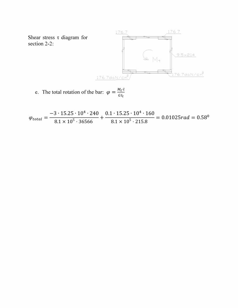
Shear stress τ diagram for
section 2-2:
e. The total rotation of the bar: =∙"
#
$" =−3 ∙ 15.25 ∙ 10 ∙ 240
8.1 × 105· 36566
+0.1 ∙ 15.25 ∙ 10 ∙ 160
8.1 × 105· 215.8
= 0.01025 = 0.58!