chapter 13 body electrical system - ford sierra net
TRANSCRIPT

Chapter 13Body electrical system
Anti-theft alarm - location, removal and refitting . . . . . . . . . . . . . . . .51Auxiliary warning system components - location, testing, removal and
refitting . . . . . . . . . . . . . . . . . . . . . . . . . . . . . . . . . . . . . . . . . . . . . .23Brake lamp switch - renewal . . . . . . . . . . . . . . . . . . . . . . . . . . . . . . .15Central door locking components - operation, removal and refitting .50Cigarette lighter - renewal . . . . . . . . . . . . . . . . . . . . . . . . . . . . . . . . .18Clock - removal and refitting . . . . . . . . . . . . . . . . . . . . . . . . . . . . . . .19Courtesy lamp and luggage compartment lamp - renewal . . . . . . . .25Courtesy lamp switch - renewal . . . . . . . . . . . . . . . . . . . . . . . . . . . . .12Direction indicator and hazard warning flasher switch assembly -
renewal . . . . . . . . . . . . . . . . . . . . . . . . . . . . . . . . . . . . . . . . . . . . . . .5Direction indicator/hazard warning flasher relay - renewal . . . . . . . . .6Electrical door mirror switch - removal and refitting . . . . . . . . . . . . .10Electrical fault finding - general information . . . . . . . . . . . . . . . . . . . . .2Electric sunroof components - removal and refitting . . . . . . . . . . . . .17Electric window components - removal and refitting . . . . . . . . . . . . .49Exterior lamp bulbs - renewal . . . . . . . . . . . . . . . . . . . . . . . . . . . . . . .48Facia panel switches - removal and refitting . . . . . . . . . . . . . . . . . . . .9Front direction indicator lamp unit - removal and refitting . . . . . . . . .44Front direction indicator side repeater lamp - removal and refitting . .45Front foglamps - removal and refitting . . . . . . . . . . . . . . . . . . . . . . . .46Fuses and relays - location and renewal . . . . . . . . . . . . . . . . . . . . . . .3General information and precautions . . . . . . . . . . . . . . . . . . . . . . . . .1Handbrake “on” warning lamp switch - renewal . . . . . . . . . . . . . . . .14Headlamps - alignment . . . . . . . . . . . . . . . . . . . . . . . . . . . . . . . . . . .42Headlamp unit - removal and refitting . . . . . . . . . . . . . . . . . . . . . . . .41Headlamp wiper motor - removal and refitting . . . . . . . . . . . . . . . . . .40Horn - removal and refitting . . . . . . . . . . . . . . . . . . . . . . . . . . . . . . . .29Horn switch assembly - removal and refitting . . . . . . . . . . . . . . . . . .11Ignition switch and lock barrel - removal and refitting . . . . . . . . . . . . .4Instrument panel - removal and refitting . . . . . . . . . . . . . . . . . . . . . .20
Instrument panel components - removal and refitting . . . . . . . . . . . .21Integral heated rear window/radio aerial amplifier - removal and
refitting . . . . . . . . . . . . . . . . . . . . . . . . . . . . . . . . . . . . . . . . . . . . . .54Interior lamp bulbs - renewal . . . . . . . . . . . . . . . . . . . . . . . . . . . . . . .27Lighting and wash/wipe switch assembly - renewal. . . . . . . . . . . . . . .7“Lights-on” warning module - renewal . . . . . . . . . . . . . . . . . . . . . . . .24 Loudspeakers - removal and refitting . . . . . . . . . . . . . . . . . . . . . . . . .55Luggage compartment lamp switch - removal and refitting . . . . . . .13Map reading lamp - removal and refitting . . . . . . . . . . . . . . . . . . . . .26Oil pressure warning lamp switch - renewal . . . . . . . . . . . . . . . . . . . .16Radio aerial (exterior-mounted) - removal and refitting . . . . . . . . . . .53Radio/cassette player - removal and refitting . . . . . . . . . . . . . . . . . . .57Radio/cassette player power amplifier - removal and refitting . . . . . .56Rear lamp unit - removal and refitting . . . . . . . . . . . . . . . . . . . . . . . .43Rear number plate lamp - removal and refitting . . . . . . . . . . . . . . . . .47Rear window washer fluid reservoir - removal and refitting . . . . . . . .39Rear window washer pump - removal and refitting . . . . . . . . . . . . . .38Rear window wiper motor - removal and refitting . . . . . . . . . . . . . . .37Reversing lamp switch - renewal . . . . . . . . . . . . . . . . . . . . . . . . . . . . .8Seat heating pad - removal and refitting . . . . . . . . . . . . . . . . . . . . . .52Speedometer cable - removal and refitting . . . . . . . . . . . . . . . . . . . .30Trip computer components - removal and refitting . . . . . . . . . . . . . .22Underbonnet lamp - removal, refitting and bulb renewal . . . . . . . . . .28Washer nozzles - removal and refitting . . . . . . . . . . . . . . . . . . . . . . .33Windscreen/headlamp washer fluid reservoir - removal and refitting . .36Windscreen/headlamp washer pump - removal and refitting . . . . . .35Windscreen wiper motor and linkage - removal and refitting . . . . . . .34Wiper arms - removal and refitting . . . . . . . . . . . . . . . . . . . . . . . . . . .32Wiper blades - renewal . . . . . . . . . . . . . . . . . . . . . . . . . . . . . . . . . . . .31Wiring diagrams - general information . . . . . . . . . . . . . . . . . . . . . . . .58
13•1
Contents
13Easy, suitable fornovice with littleexperience
Fairly easy, suitablefor beginner withsome experience
Fairly difficult,suitable for competentDIY mechanic
Difficult, suitable forexperienced DIYmechanic
Very difficult,suitable for expertDIY or professional
Degrees of difficulty

System type . . . . . . . . . . . . . . . . . . . . . . . . . . . . . . . . . . . . . . . . . . . 12 volt, negative earth
Bulbs Fittings WattageHalogen headlamps . . . . . . . . . . . . . . . . . . . . . . . . . . . . . . . . . . . . . . . . H4 60/55Auxiliary driving lamps . . . . . . . . . . . . . . . . . . . . . . . . . . . . . . . . . . . . . . H3 55Front foglamps . . . . . . . . . . . . . . . . . . . . . . . . . . . . . . . . . . . . . . . . . . . . H3 55Side lamps . . . . . . . . . . . . . . . . . . . . . . . . . . . . . . . . . . . . . . . . . . . . . . . Glass base 5Direction indicator lamps . . . . . . . . . . . . . . . . . . . . . . . . . . . . . . . . . . . . Bayonet 21Brake/tail lamps . . . . . . . . . . . . . . . . . . . . . . . . . . . . . . . . . . . . . . . . . . . Bayonet 21/4Reversing lamp(s) . . . . . . . . . . . . . . . . . . . . . . . . . . . . . . . . . . . . . . . . . . Bayonet 21Rear foglamp(s) . . . . . . . . . . . . . . . . . . . . . . . . . . . . . . . . . . . . . . . . . . . . Bayonet 21Rear number plate lamps . . . . . . . . . . . . . . . . . . . . . . . . . . . . . . . . . . . . Glass base 5Luggage compartment lamp . . . . . . . . . . . . . . . . . . . . . . . . . . . . . . . . . Bayonet 10Underbonnet lamp . . . . . . . . . . . . . . . . . . . . . . . . . . . . . . . . . . . . . . . . . Bayonet 10Courtesy lamp(s) . . . . . . . . . . . . . . . . . . . . . . . . . . . . . . . . . . . . . . . . . . . Bayonet 10Map reading lamps . . . . . . . . . . . . . . . . . . . . . . . . . . . . . . . . . . . . . . . . . Glass base 5Vanity mirror illumination lamp . . . . . . . . . . . . . . . . . . . . . . . . . . . . . . . . Festoon 3Glove compartment lamp . . . . . . . . . . . . . . . . . . . . . . . . . . . . . . . . . . . . Glass base 3Ashtray lamp . . . . . . . . . . . . . . . . . . . . . . . . . . . . . . . . . . . . . . . . . . . . . . Glass base 1.2Warning lamps . . . . . . . . . . . . . . . . . . . . . . . . . . . . . . . . . . . . . . . . . . . . Glass base 1.2 or 2.5Instrument illumination lamps . . . . . . . . . . . . . . . . . . . . . . . . . . . . . . . . . Glass base 1.2 or 2.5Heater control illumination lamp . . . . . . . . . . . . . . . . . . . . . . . . . . . . . . . Glass base 1Automatic transmission gear selector lamp . . . . . . . . . . . . . . . . . . . . . . Bayonet 1.2Clock illumination lamp . . . . . . . . . . . . . . . . . . . . . . . . . . . . . . . . . . . . . Bayonet 1.4Cigarette lighter lamp . . . . . . . . . . . . . . . . . . . . . . . . . . . . . . . . . . . . . . . Glass base 1.2
Torque wrench settings Nm lbf ftTrip computer fuel flow sensor unit fuel pipe unions . . . . . . . . . . . . . . . 14 to 17 10 to 13
General informationThe electrical system is of the 12 volt.
negative earth type. Electricity is generated byan alternator, belt-driven from the crankshaftpulley. A lead-acid storage battery provides areserve of power for starting and when thedemands of the system temporarily exceedthe alternator output.
The battery negative terminal is connectedto “earth” - vehicle metal - and most electricalsystem components are wired so that theyonly receive a positive feed, the currentreturning via vehicle metal. This means thatthe component mounting forms part of thecircuit. Loose or corroded mountings cantherefore cause apparent electrical faults.
Many semiconductor devices are used inthe electrical system, both in the “blackboxes” which control vehicle functions and inother components. Semiconductors are verysensitive to excessive (or wrong polarity)voltage, and to extremes of heat. Observe theappropriate precautions to avoid damage.
PrecautionsIt is necessary to take extra care when
working on the electrical system to avoiddamage to semi-conductor devices (diodesand transistors), and to avoid the risk ofpersonal injury. In addition to the precautionsgiven in the “Safety first!” Section at thebeginning of this manual, take note of thefollowing points when working on the system.
Always remove rings, watches, etc beforeworking on the electrical system. Even with
the battery disconnected, capacitivedischarge could occur if a component liveterminal is earthed through a metal object.This could cause a shock or nasty burn.
Do not reverse the battery connections.Components such as the alternator or anyother having semi-conductor circuitry couldbe irreparably damaged.
If the engine is being started using jumpleads and a slave battery, connect thebatteries positive to positive and negative tonegative. This also applies when connecting abattery charger.
Never disconnect the battery terminals, oralternator multi-plug connector, when theengine is running.
The battery leads and alternator multi-plugmust be disconnected before carrying out anyelectric welding on the car.
Never use an ohmmeter of the typeincorporating a hand cranked generator forcircuit or continuity testing.
Note: Refer to the precautions given in “Safetyfirst!” and in Section 1 of this Chapter beforestarting work. The following tests relate to testingof the main electrical circuits, and should not beused to test delicate electronic circuits (such asanti-lock braking systems), particularly where anelectronic control unit (ECU) is involved.
General1 A typical electrical circuit consists of anelectrical component, any switches, relays,motors, fuses, fusible links or circuit breakersrelated to that component, and the wiring and
connectors which link the component to boththe battery and the chassis. To help to pinpoint aproblem in an electrical circuit, wiring diagramsare included at the end of this Chapter.2 Before attempting to diagnose an electricalfault, first study the appropriate wiringdiagram, to obtain a more completeunderstanding of the components included inthe particular circuit concerned. The possiblesources of a fault can be narrowed down bynoting whether other components related tothe circuit are operating properly. If severalcomponents or circuits fail at one time, theproblem is likely to be related to a shared fuseor earth connection.3 Electrical problems usually stem fromsimple causes, such as loose or corrodedconnections, a faulty earth connection, ablown fuse, a melted fusible link, or a faultyrelay. Visually inspect the condition of allfuses, wires and connections in a problemcircuit before testing the components. Usethe wiring diagrams to determine whichterminal connections will need to be checked,in order to pinpoint the trouble-spot.4 The basic tools required for electrical fault-finding include: a circuit tester or voltmeter (a12-volt bulb with a set of test leads can alsobe used for certain tests), a self-powered testlight (sometimes known as a continuity tester),an ohmmeter (to measure resistance), abattery and set of test leads, and a jumperwire, preferably with a circuit breaker or fuseincorporated, which can be used to bypasssuspect wires or electrical components.Before attempting to locate a problem withtest instruments, use the wiring diagram todetermine where to make the connections.
2 Electrical fault-finding - generalinformation
1 General information andprecautions
13•2 Body electrical system
Specifications

5 To find the source of an intermittent wiringfault (usually due to a poor or dirtyconnection, or damaged wiring insulation), anintegrity test can be performed on the wiring,which involves moving the wiring by hand, tosee if the fault occurs as the wiring is moved.It should be possible to narrow down thesource of the fault to a particular section ofwiring. This method of testing can be used inconjunction with any of the tests described inthe following sub-Sections.6 Apart from problems due to poorconnections, two basic types of fault canoccur in an electrical circuit - open-circuit, orshort-circuit.7 Open-circuit faults are caused by a breaksomewhere in the circuit, which preventscurrent from flowing. An open-circuit fault willprevent a component from working, but willnot cause the relevant circuit fuse to blow.8 Short-circuit faults are caused by a “short”somewhere in the circuit, which allows thecurrent flowing in the circuit to “escape” alongan alternative route, usually to earth. Short-circuit faults are normally caused by abreakdown in wiring insulation, which allows afeed wire to touch either another wire, or anearthed component such as the bodyshell. Ashort-circuit fault will normally cause therelevant circuit fuse to blow.Note: A short-circuit that occurs in the wiring
between a circuit’s battery supply and its fusewill not cause the fuse in that particular circuitto blow. This part of the circuit is unprotected- bear this in mind when fault-finding on thevehicle’s electrical system.
Finding an open-circuit9 To check for an open-circuit, connect onelead of a circuit tester or voltmeter to eitherthe negative battery terminal or a known goodearth.10 Connect the other lead to a connector inthe circuit being tested, preferably nearest tothe battery or fuse.11 Switch on the circuit, bearing in mind thatsome circuits are live only when the ignitionswitch is moved to a particular position.12 If voltage is present (indicated either bythe tester bulb lighting or a voltmeter reading,as applicable), this means that the section ofthe circuit between the relevant connectorand the battery is problem-free.13 Continue to check the remainder of thecircuit in the same fashion.14 When a point is reached at which novoltage is present, the problem must liebetween that point and the previous test pointwith voltage. Most problems can be traced toa broken, corroded or loose connection.
Finding a short-circuit15 To check for a short-circuit, firstdisconnect the load(s) from the circuit (loadsare the components which draw current froma circuit, such as bulbs, motors, heatingelements, etc).16 Remove the relevant fuse from the circuit,and connect a circuit tester or voltmeter to thefuse connections.
17 Switch on the circuit, bearing in mind thatsome circuits are live only when the ignitionswitch is moved to a particular position.18 If voltage is present (indicated either bythe tester bulb lighting or a voltmeter reading,as applicable), this means that there is ashort-circuit.19 If no voltage is present, but the fuse stillblows with the load(s) connected, thisindicates an internal fault in the load(s).
Finding an earth fault20 The battery negative terminal is connectedto “earth” - the metal of theengine/transmission and the car body - andmost systems are wired so that they onlyreceive a positive feed, the current returning viathe metal of the car body. This means that thecomponent mounting and the body form partof that circuit. Loose or corroded mountingscan therefore cause a range of electrical faults,ranging from total failure of a circuit, to apuzzling partial fault. In particular, lights mayshine dimly (especially when another circuitsharing the same earth point is in operation),motors (eg wiper motors or the radiator coolingfan motor) may run slowly, and the operation ofone circuit may have an apparently-unrelatedeffect on another. Note that on many vehicles,earth straps are used between certaincomponents, such as the engine/transmissionand the body, usually where there is no metal-to-metal contact between components, due toflexible rubber mountings, etc.21 To check whether a component isproperly earthed, disconnect the battery, andconnect one lead of an ohmmeter to a knowngood earth point. Connect the other lead tothe wire or earth connection being tested. Theresistance reading should be zero; if not,check the connection as follows.22 If an earth connection is thought to befaulty, dismantle the connection, and cleanback to bare metal both the bodyshell and thewire terminal, or the component’s earthconnection mating surface. Be careful toremove all traces of dirt and corrosion, thenuse a knife to trim away any paint, so that aclean metal-to-metal joint is made. Onreassembly, tighten the joint fastenerssecurely; if a wire terminal is being refitted,use serrated washers between the terminal
and the bodyshell, to ensure a clean andsecure connection. When the connection isremade, prevent the onset of corrosion in thefuture by applying a coat of petroleum jelly orsilicone-based grease, or by spraying on (atregular intervals) a proprietary ignition sealer.
Location1 The main fuses and relays are located in abox in the engine compartment on the right-hand side of the bulkhead. The circuitsprotected are identified by symbols on theunderside of the fusebox cover. On certainmodels, additional relays and fuses are locatedin various positions beneath the facia panels. Ifuncertain of the location of an auxiliary relay orfuse, it is suggested that a Ford dealer isconsulted, as the relay and fuse locations varysubstantially depending on model.
Renewal2 Always renew a fuse with one of identicalrating and never renew it more than oncewithout finding the source of the trouble(usually a short circuit). Always switch off theignition before renewing a fuse or relay, andwhen renewing the wiper motor fuse keep thehands clear of the wiper linkage as it mayreturn to the parked position. Note that thefuses are colour-coded as follows:
10A Red15A Blue20A Yellow25A Natural10A Green
3 Access to the fuses and relays in thefusebox is gained by removing the loosecover and spring clip (if fitted), pulling theplastic clip and removing the cover. All fusesand relays are a push fit (see illustrations).The fuse/relay plate can be released from thefusebox for access to the wiring by carefullylevering the plastic lugs around the perimeterof the plate.4 For details of direction indicator/hazardwarning flasher relay removal and refitting,refer to the relevant Section of this Chapter.
3 Fuses and relays - location andrenewal
Body electrical system 13•3
13
3.3b Fusebox cover removed to exposefuses and relays (1.8 CVH model shown)
3.3a Remove the loose cover for access tothe fusebox cover

Removal1 Disconnect the battery negative lead.2 For improved access, remove the securingscrews and unclip the lower and uppersteering column shrouds.3 Insert the ignition key and turn to position“I”, then, working through the access hole,depress the spring clip using a suitable tooland pull the key to withdraw the lock barreland cylinder from the ignition switch housing.The spring clip access hole is shown (seeillustration). Note that, on certain models, thespring clip must be released by inserting thetool through a small circular hole at the top ofthe switch housing, above the rectangular slotshown. Slight movement of the key may benecessary to allow removal of the barrel andcylinder.4 To remove the lock barrel from the cylinderinsert the key fully into the barrel and removethe retaining circlip, taking care not todamage the circlip location, then withdraw thekey approximately 5.0 mm (0.2 in) to retractthe lock barrel securing lug, and withdraw thebarrel from the cylinder.5 To remove the ignition switch, disconnectthe wiring plug, then remove the two grubscrews and withdraw the switch.
Refitting6 Refitting is a reversal of removal, bearing inmind the following points.7 Note that the lock barrel can only be fittedto the cylinder in one position, and check withthe key fully inserted that the barrel can beturned from position “O” to “Ill” satisfactorily.8 The open jaws of the lock barrel retainingcirclip must align with the keyway register onthe cylinder, and the cylinder retaining circlipmust locate in the slot in the ignition switchhousing.9 On completion, check the operation of thesteering lock and ignition switch in allpositions.
1 Disconnect the battery negative lead.2 Remove the securing screws and unclip thelower and upper steering column shrouds.3 Remove the two securing screws anddisconnect the two wiring plugs, thenwithdraw the switch from the steering column.4 Refitting is a reversal of removal.
1 Disconnect the battery negative lead.
2 The relay is located on a bracket above thesteering column. Access is gained either byremoving the driver’s side lower facia panel orthe instrument panel.3 Unclip the relay from the bracket, anddisconnect the wiring plug (see illustration).4 Refitting is a reversal of removal. Check forcorrect operation before refitting the faciapanel or instrument panel.
The procedure is identical to that describedfor the direction indicator switch, except forthe additional removal and refitting of an earthlead (see illustration).
1 For automatic transmission models, refer toChapter 7, Part B. For manual gearboxmodels, proceed as follows:2 Disconnect the battery negative lead.3 Apply the handbrake, jack up the front ofthe vehicle and support on axle stands (see“Jacking and Vehicle Support”).4 Working underneath the vehicle,disconnect the wiring plug, then unscrew theswitch from the gearbox extension housing.5 Refitting is a reversal of removal, but makesure that the wiring is routed clear of theexhaust system.
1 Disconnect the battery negative lead.
Rocker switches and push buttonswitches2 Using a thin-bladed screwdriver, carefullyprise the switch from the facia panel.3 Disconnect the wiring plug and withdrawthe switch. 4 Refitting is a reversal of removal.
Instrument panel illumination andintermittent wipe rheostats 5 Proceed as described in paragraphs 2 to 4.
Heater blower switch6 Carefully pull off the switch knob, usingpliers with padded jaws if necessary.7 Using a thin-bladed screwdriver, prise outthe switch front plate from the facia panel.8 Squeeze the switch retaining tabs, thenwithdraw the switch and disconnect the wiringplug (see illustration).9 Refitting is a reversal of removal.
Loudspeaker balance joystick10 Using a thin-bladed screwdriver, carefullyprise the joystick front plate from the faciapanel.11 Twist the joystick assembly retaining ringanti-clockwise and remove the ring.12 Working behind the facia panel,disconnect the wiring plug and slide out thejoystick assembly.
9 Facia panel switches - removaland refitting
8 Reversing lamp switch -renewal
7 Lighting and wash/wipeswitch assembly - renewal
6 Direction indicator/hazardwarning flasher relay - renewal
5 Direction indicator and hazardwarning flasher switchassembly - renewal
4 Ignition switch and lock barrel- removal and refitting
13•4 Body electrical system
4.3 Ignition switch lock barrel spring cliplocation (arrowed)
7.1 Lighting and wash/wipe switchassembly earth lead securing screw
(arrowed)9.8 Heater blower switch removal. Switch
retaining tabs arrowed
6.3 Direction indicator/hazard warningflasher relay location (arrowed)

13 Refitting is a reversal of removal, but notethat the wiring plug can only be fitted in oneposition, and ensure that the joystickassembly locating lug engages in thecorresponding hole in the facia panel.
1 Disconnect the battery negative lead.
Models up to 19872 Using a thin-bladed screwdriver, carefullyprise the switch from the door trim panel.3 Disconnect the wiring plug and withdrawthe switch (see illustration). 4 Refitting is a reversal of removal.
Models from 19875 Prise the securing screw cover from the
mirror control panel, then remove the screwand withdraw the control panel.6 Depress the switch retaining tang, thenwithdraw the switch from the control paneland disconnect the wiring plug.7 Refitting is a reversal of removal.
1 Disconnect the battery negative lead.
Switch
Models up to 19872 Pull the trim insert from the centre of thesteering wheel, and disconnect the lead fromthe horn push.3 Disconnect the two leads from the horn slipring, then remove the two securing screwsand withdraw the switch assembly (seeillustration). 4 Refitting is a reversal of removal, but checkthe operation of the switch on completion.
Models from 19875 Using a thin-bladed screwdriver, carefullyprise the trim insert from the centre of thesteering wheel. Disconnect the wire.6 Prise the steering wheel centre disc fromthe steering wheel, and disconnect the wire(see illustration).7 Refitting is a reversal of removal.
Slip ring8 Remove the steering wheel.9 On models up to 1987, remove the switchas described in paragraph 3.10 Release the three slip ring retaining tangsand withdraw the slip ring from the steeringwheel.11 Refitting is a reversal of removal.
Slip ring contact finger12 Remove the steering wheel.13 Remove the securing screws and unclipthe lower and upper steering column shrouds.14 Disconnect the contact finger wiring plug,and pull the contact finger housing from itsmounting (see illustration).15 Refitting is a reversal of removal.
1 Disconnect the battery negative lead.2 Open the door and remove the switchsecuring screw.3 Withdraw the switch from the door pillarand pull the wiring out sufficiently to prevent itfrom springing back into the pillar (seeillustration).4 Disconnect the wiring and remove theswitch.5 Refitting is a reversal of removal.
1 Disconnect the battery negative lead.
Models up to 1987 2 A level-sensitive switch is fitted to thetailgate. 3 Unclip the tailgate trim panel. 4 Disconnect the wiring from the switchterminal, then remove the securing screw andwithdraw the switch, noting its fitted position(see illustration).5 Refitting is a reversal of removal, but ensurethat the switch is refitted in its originalposition, as noted during removal, and testthe operation of the switch on completion.
Models from 19876 Where applicable, unclip the tailgate/boottrim panel.
13 Luggage compartment lampswitch - removal and refitting
12 Courtesy lamp switch -renewal
11 Horn switch assembly -removal and refitting
10 Electric door mirror switch -removal and refitting
Body electrical system 13•5
13
11.6 Prise the trim insert from the steeringwheel, followed by the centre disc -
models from 1987
13.4 Luggage compartment lamp switchlocation - models up to 1987
12.3 Withdrawing a courtesy lamp switch11.14 Horn switch slip ring contact fingerremoval
11.3 Horn switch removal - models up to1987. Switch securing screws arrowed
10.3 Disconnect the wiring plug from thedoor mirror switch - models up to 1987

7 Unclip the switch from the lock assembly,disconnect the wiring plug and remove theswitch.8 Refitting is a reversal of removal.
1 Disconnect the battery negative lead.2 Working inside the vehicle, remove thehandbrake lever rubber gaiter and/or thecentre console, as necessary.3 Disconnect the wiring connector from theswitch, then remove the two securing screwsand withdraw the switch from the handbrakelever (see illustration).4 Refitting is a reversal of removal.
1 Disconnect the battery negative lead.2 Unclip the trim panel from the lower edge ofthe driver’s side lower facia trim panel. Ifrequired for improved access, remove thelower facia trim panel.3 Disconnect the wiring from the terminal onthe switch, then twist the switch anti-clockwise and remove it (see illustration).4 When refitting, insert the switch into itsaperture in the pedal bracket, then push theswitch inwards until the switch barrel touchesthe pedal. Ensure that the pedal is not movedfrom its stop. Twist the switch clockwise to lockit in position. No further adjustment is necessary.5 Further refitting is a reversal of removal, butcheck the operation of the switch oncompletion.
1 Disconnect the battery negative lead.2 The switch is located towards the left-handrear of the cylinder block on SOHC models(see illustration), towards the right-hand rearof the cylinder block on CVH models and onthe right-hand side of the cylinder block,between the core plugs, on DOHC models.
3 Disconnect the wiring from the switchterminal, then unscrew and withdraw theswitch. Be prepared for some oil spillage.4 Clean the threads of the switch and its seatbefore refitting.5 After refitting, run the engine and check foroil leaks around the switch, then stop theengine and check the oil level, topping-up ifnecessary.
Switch1 Disconnect the battery negative lead.2 Using a thin-bladed screwdriver, carefullyprise the switch from the overhead console.3 Disconnect the wiring plug and remove theswitch. 4 Refitting is a reversal of removal.
Relay5 Remove the overhead console.6 Unclip the relay from the motor assemblyand disconnect the wiring plug (seeillustration).7 Refitting is a reversal of removal.
Motor8 Remove the overhead console.9 Disconnect the motor wiring plug.10 Unscrew the three securing bolts, andwithdraw the motor assembly from the roof.11 Refitting is a reversal of removal, butensure that the drive gear is aligned with theroof operating mechanism.
1 Disconnect the battery negative lead.2 Working behind the facia panel, disconnectthe wiring, then push out the lighter assemblythrough the front of the facia panel.3 If required, the illumination ring assemblycan now be withdrawn after removing thebulbholder.4 Refitting is a reversal of removal.
1 Disconnect the battery negative lead.
Standard clock2 Using a thin-bladed screwdriver, carefullyprise the clock from the facia panel.3 Disconnect the wiring plug and withdrawthe clock. 4 Refitting is a reversal of removal.
Multi-function digital/analogueclock5 Remove the single screw from the top edgeof the facia panel in which the clock ishoused, then withdraw the facia panel.6 Remove the four now exposed securingscrews, disconnect the wiring plug, andwithdraw the clock (see illustration).7 Refitting is a reversal of removal.
19 Clock - removal and refitting
18 Cigarette lighter - renewal
17 Electric sunroof components- removal and refitting
16 Oil pressure warning lampswitch - renewal
15 Brake lamp switch - renewal
14 Handbrake “on” warninglamp switch - renewal
13•6 Body electrical system
14.3 Handbrake “on” warning lamp switchlocation (arrowed)
16.2 Oil pressure warning lamp switchlocation (arrowed) - SOHC engine
19.6 Multi-function digital/analogue clocksecuring screws (arrowed)
17.6 Electric sunroof relay (A) and motorsecuring bolts (B)
15.3 Brake lamp switch location (arrowed)

Models up to 19921 Disconnect the battery negative lead.2 Remove the securing screws and unclip thelower and upper steering column shrouds.3 Where applicable, remove the instrumentpanel illumination and intermittent wiperrheostats.4 Unclip the cover for access to the lowerright-hand instrument panel surroundsecuring screw (see illustrations).5 Remove the two upper and two lowersecuring screws, and withdraw the instrumentpanel surround (see illustration).6 On models fitted with a trip computer,unscrew the knurled nut and disconnect the
speedometer cable from the speed senderunit on the engine compartment bulkhead.7 Detach the speedometer cable grommetfrom the engine compartment bulkhead.8 Remove the two upper and two lowersecuring screws, and withdraw the instrumentpanel sufficiently to disconnect thespeedometer cable and the wiring plugs. Thespeedometer cable can be released bypushing the ribbed surface towards the centreof the cable to free the catch. Remove theinstrument panel (see illustration).9 Refitting is a reversal of removal but whereapplicable, ensure that the speedometercable rubber sleeve is in place over the squareInner drive on the cable connector, and not inthe speedometer head.10 On completion, pull the speedometercable from within the engine compartment toensure that the cable is straight between theinstrument panel and the bulkhead grommet.
Models from 199211 The procedure is as described above butnote that both instrument panel surroundlower securing screws are located beneathplastic covers (see illustration).12 The steering column shrouds are securedby six screws - five through the lower shroud,and one through the upper shroud.
1 Remove the instrument panel.
Panel illumination and warninglamp bulbs2 Twist the relevant bulbholder anti-clockwise and withdraw it from the printedcircuit board on the rear of the instrumentpanel.3 The bulbs may be either a push-fit in thebulbholder, or integral with the bulbholder inwhich case the bulb and bulbholder must berenewed as a unit (see illustrations).4 Refitting is a reversal of removal.
Panel lens5 Remove the three upper and three lowersecuring screws and withdraw the lens fromthe instrument panel.6 Refitting is a reversal of removal, but ensurethat the two locating pegs on the uppercorners of the instrument panel protrudethrough the lens, and locate the lugs on thelower edge of the lens in the cut-outs in theinstrument panel.
Printed circuit board7 Using a thin-bladed screwdriver, unclip andremove the wiring plug socket.8 Remove all the illumination and warninglamp bulbs as described earlier in thisSection.9 Remove all the nuts and washers from theprinted circuit board terminals.10 Unclip the printed circuit board from theretainers at the back of the instrument panel,and carefully withdraw the board over theterminal pins on the gauges.11 Refitting is a reversal of removal.
21 Instrument panel components- removal and refitting
20 Instrument panel - removaland refitting
Body electrical system 13•7
13
20.5 Removing an upper instrument panelsurround securing screw
21.3b Removing an instrument panelillumination bulb - bulb is integral with
bulbholder
21.3a Removing an instrument panelwarning lamp bulb - bulb is a push-fit in
the bulbholder
20.11 Removing an instrument panelsurround lower securing screw (cover
removed)
20.8 Withdraw the instrument panel anddisconnect the wiring plugs
20.4b . . . for access to the lower right-hand instrument panel surround securing
screw
20.4a Unclip the cover . . .

Speedometer12 Remove the panel lens (paras. 5 and 6).13 Remove the two screws securing thespeedometer to the rear of the instrumentpanel, taking care not to lose the two brushes.Withdraw the speedometer through the frontof the instrument panel.14 Refitting is a reversal of removal.
Tachometer
Models up to 199015 Remove the four or five securing screws,as applicable, and separate the two halves ofthe instrument panel housing.16 Remove the three securing nuts andwashers from the rear of the instrument panelhousing, and withdraw the tachometer.17 Refitting is a reversal of removal, but ensurethat the tachometer engages with the locatingribs in the housing around the dial edge.
Models from 199018 The procedure is as described above butbefore the tachometer can be withdrawn fromthe instrument panel housing, the printed circuitboard must be carefully pulled from thetachometer terminals. Ensure that the printedcircuit board is pushed fully home when refitting.
Fuel and temperature gauges
Models up to 198719 Remove the four securing screws andseparate the two halves of the instrumentpanel housing.20 Remove the four securing nuts and washersfrom the rear of the instrument panel housing,and withdraw the combined gauge assembly.21 Refitting is a reversal of removal.
Models from 198722 Remove the five securing screws andseparate the two halves of the instrumentpanel housing.23 Remove the printed circuit board asdescribed previously in this Section.24 On “low specification” models, remove thetwo securing screws from the front of thegauge assembly, then withdraw the combinedgauge assembly from the printed circuit board.
25 On “high specification” models, simplywithdraw the combined gauge assembly fromthe printed circuit board.26 Refitting is a reversal of removal, but on“high specification” models, ensure that thegauge assembly engages with the locatingribs in the housing around the gauge edge.
1 Disconnect the battery negative lead
Computer module2 Remove the single screw from the top edgeof the facia panel in which the module ishoused, then withdraw the facia panel.3 Remove the four now exposed securingscrews, disconnect the wiring plug, andcarefully withdraw the module. On latermodels a retaining lug must be depressedbefore the wiring plug can be disconnected.4 Where applicable, the mounting bracketscan be removed from the module byunscrewing the securing nuts.5 If necessary, the illumination bulb can beremoved from the module by twisting thebulbholder anti-clockwise using a pair of long-nosed pliers. The bulb is a push-fit in the holder.6 Refitting is a reversal of removal.
Speed sender unitModels up to 19877 The speed sender unit is located in theengine compartment on the right-hand side ofthe bulkhead.8 Disconnect the plug from the sender unit.9 Unscrew the two knurled nuts from thesender unit and disconnect the twospeedometer cables.10 Remove the three securing screws andremove the bracket and sender unit.11 Unscrew and remove the securing nutand washer, and separate the sender unitfrom the bracket.12 Refitting is a reversal of removal.
Models from 198713 Detach the wiring, hose retainers and
cover panel from the bulkhead to gain accessto the sender unit.14 Proceed as shown in paragraphs 7 to 9.15 Remove the retaining nut and washer andwithdraw the sender unit.16 Refitting is a reversal of removal.
Fuel flow sensor unit
Carburettor models17 The fuel flow sensor is located on the left-hand side of the engine compartment (seeillustration).18 Disconnect the wiring plug from thesensor unit.19 Refer to the “Safety first!” Section at thefront of the manual, and the precautions inChapter 4, then disconnect the fuel pipes fromthe sensor unit. Note that on models up to1987 there are three fuel pipe connections, andon models from 1987 there are two fuel pipeconnections. Be prepared for fuel spillage.20 Remove the three securing screws andwithdraw the bracket and sender unit.21 Unscrew the four nuts and separate thesender unit from the bracket.22 Refitting is a reversal of removal, butensure that the flow direction arrows on thefuel inlet and outlet ports are correctlyorientated, and that the arrow on the rear ofthe unit points to the top.
Fuel injection models23 The sensor is located on the left-handside of the engine compartment.24 Disconnect the wiring plug from thesensor unit.25 Refer to the “Safety first!” Section at thefront of the manual, and the precautions inChapter 4, then unscrew the two union nutsand disconnect the fuel pipes from the sensorunit. Be prepared for fuel spillage.26 Remove the two securing screws andwithdraw the sensor unit.27 Refitting is a reversal of removal, butensure that the No 2 injector fuel pipe is fittedto the sensor unit outlet port marked with anarrow, and ensure that the union washers arein place (see illustration). Tighten the fuelpipe unions to the specified torque.
22 Trip computer components -removal and refitting
13•8 Body electrical system
22.17 Trip computer fuel flow sensor unit location - carburettormodels up to 1987. Bracket retaining screws arrowed
22.27 Trip computer fuel flow sensor unit - fuel injection models
A Wiring plugB Hollow boltsC Inlet port banjo connector
D BracketE Outlet port banjo connectorF Sensor unit

Location1 The AWS control unit, and (when fitted) thebulb failure monitor, are located behind theglovebox on models up to 1987.2 On models from 1987, the control and bulbfailure modules are located behind the driver’sside footwell trim panel.
Testing3 Thorough testing and fault finding shouldbe left to a Ford dealer or other electricalspecialist, having test equipment. Unskilled oruninformed testing may cause damage.4 Investigation of malfunctions should beginby checking that all wiring is intact andsecurely connected. If checking wires orsensors for continuity, always disconnect thecontrol unit and/or bulb failure monitor beforeso doing, otherwise damage may be caused.5 Note that false oil level readings can result ifthe car is parked on a slope. False bulb failurewarnings may occur if incorrect wattage bulbsare fitted.
Removal and refitting6 Disconnect the battery negative lead.
Warning lamp bulbs7 Remove the single screw from the top edgeof the facia panel in which the warning lampsare housed, then withdraw the facia panel(see illustration).8 Twist the relevant bulbholder through 90º toremove it from the rear of the facia panel. Thebulb is integral with the bulbholder and mustbe renewed as a unit (see illustration).9 Refitting is a reversal of removal.
Graphic display unit and bulbs10 Remove the clock or trip computer.11 Remove the display unit retaining screwand the retainer, then pull the unit forwardsand disconnect the wiring plug using a thin-bladed screwdriver (see illustrations).12 To renew a bulb, remove the two securingscrews and pull the circuit board from theback of the unit to reveal the bulbs. The bulbsare a push-fit.13 Refitting is a reversal of removal.
Control unit and bulb failure monitor14 Unclip the trim panel from the lower edgeof the passenger side lower facia panel.15 On models up to 1987, pull off the twoclips to release the control unit/bulb failuremonitor mounting bracket. Depress theretaining tab and disconnect the relevantwiring plug, then remove the two securingscrews and withdraw the control unit/bulbfailure monitor (see illustration).16 On models from 1987, release theretaining tang and carefully slide the controlunit/bulb failure monitor downwards. Depressthe retaining tab and disconnect the relevantwiring plug, then withdraw the controlunit/bulb failure monitor.17 Refitting is a reversal of removal. Notethat when both a control unit and bulb failuremonitor are fitted, the control unit wiring plugis coloured brown, and the bulb failuremonitor wiring plug is coloured green.
Ice warning sender18 This sender is located beneath the frontpanel on the right-hand side of the vehicle.19 Where necessary, for improved accessremove the horn.20 Depress the two retaining tangs,disconnect the wiring plug and withdraw thesender unit from the slot in the front panel.21 Refitting is a reversal of removal.
Door/tailgate/boot lid ajar switches22 Remove the relevant lock.23 Pull the switch from its location in the lockbody, disconnect the wiring plug (if notalready done) and withdraw the switch (seeillustration).
24 Refitting is a reversal of removal.
Low coolant level sensor 25 Refer to Chapter 3.
Low washer fluid level switch26 Syphon out the contents of the reservoir,then prise the switch from its grommet using athin-bladed screwdriver. Disconnect thewiring plug.27 Refitting is a reversal of removal, using anew grommet if necessary. Use a little liquiddetergent as a lubricant.28 On completion, refill the reservoir.
Low fuel level switch29 The switch is integral with the fuel levelsender unit. Details of fuel level sender unitremoval and refitting are given in Chapter 4.
Low oil level switch30 The switch is integral with the oil leveldipstick. To remove, simply withdraw the
23 Auxiliary warning systemcomponents - location,testing, removal and refitting
Body electrical system 13•9
13
23.11a Removing the graphic display unitretaining screw
23.23 Door lock and door ajar switch23.15 Auxiliary warning system control unitlocation
23.11b Disconnecting the wiring plug fromthe graphic display unit
23.8 Removing an auxiliary warning lampbulb
23.7 Remove the screw from the warninglamp facia panel

dipstick from its tube and disconnect thewiring plug.31 Refitting is a reversal of removal.
1 Remove the instrument panel.2 Unclip the direction indicator relay from thesteering column support bracket (seeillustration).3 Unclip the “lights-on” warning module fromthe steering column support bracket,disconnect the wiring plug and remove themodule.4 Refitting is a reversal of removal.
1 Disconnect the battery negative lead.2 To remove a lamp, simply prise it from itslocation, using a thin-bladed screwdriver, anddisconnect the wiring (see illustrations).When working on an overhead console-mounted courtesy lamp, disconnect thewiring between the map reading lamps andthe courtesy lamp before removing thecourtesy lamp.3 Refitting is a reversal of removal.
1 Disconnect the battery negative lead. 2 Remove the courtesy lamp and disconnectthe map reading lamp wires. 3 Push the map reading lamp out of itslocation by inserting a finger through thecourtesy lamp aperture. 4 Refitting is a reversal of removal.
1 Disconnect the battery negative lead.
Courtesy lamp 2 Remove the courtesy lamp. 3 Unclip the bulb from the lamp. On modelsfitted with an overhead console and mapreading lamps, the courtesy lamp reflectormust be unclipped for access to the bulb (seeillustration). 4 Refitting is a reversal of removal.
Map reading lamp 5 Remove the map reading lamp. 6 Pull the bulbholder from the rear of thelamp. The bulb is a push fit in the bulbholder(see illustration). 7 Refitting is a reversal of removal.
Glove compartment lamp 8 Open the glove compartment and pull thebulb from its holder.9 Refitting is a reversal of removal.
Ashtray lamp 10 Open the ashtray and remove the trayfrom its housing. 11 Pull the bulbholder from the housing. Thebulb is a push fit in the bulbholder. 12 Refitting is a reversal of removal.
Heater blower switch illuminationlamp 13 Carefully pull off the switch knob, usingpliers with padded jaws if necessary. The bulbis a bayonet fit in the end of the switch shaft. 14 Refitting is a reversal of removal.
Heater control illumination lamp 15 Refer to Chapter 12.
Vanity mirror illumination lamp 16 Lower the sun visor and, using a thin-bladed screwdriver, prise out the mirror anddiffuser assembly. Remove the festoon bulb(s)from its/their spring contacts. 17 Refitting is a reversal of removal.
Hazard flasher switch lamp 18 Remove the securing screws and unclipthe upper steering column shroud. 19 Ensure that the switch is in the “on”position, then pull off the switch cap/bulbcover. Carefully pull the bulb from the switchusing a pair of pliers with padded jaws. 20 Refitting is a reversal of removal.
Automatic transmission gearselector illumination lamp 21 Unscrew the selector lever handle fromthe threaded end of the lever, then remove thethree securing screws and withdraw thecentre console front upper panel. 22 Pull of the selector gate cover to exposethe bulbholder. The bulb is a bayonet fit in thebulbholder. 23 Refitting is a reversal of removal.
Luggage compartment lamp 24 Remove the lamp by carefully prising itfrom its location using a thin-bladedscrewdriver. Unclip and remove the bulb (seeillustration).25 Refitting is a reversal of removal.
27 Interior lamp bulbs - renewal
26 Map reading lamp - removaland refitting
25 Courtesy lamp and luggagecompartment lamp - renewal
24 “Lights-on” warning module- renewal
13•10 Body electrical system
24.2 “Lights-on” warning module location
A “Lights-on” warning moduleB Direction indicator relayC “Lights-on” warning module wiring plug
25.2b Removing a luggage compartmentlamp
27.6 Removing a map reading lamp bulb27.3 Overhead console-mounted courtesylamp bulb (arrowed)
25.2a Removing a courtesy lamp

Clock illumination lamp 26 Remove the clock. 27 The bulb is a bayonet fit in the rear of theclock. 28 Refitting is a reversal of removal.
1 Disconnect the battery negative lead.
Removal and refitting 2 Detach the wiring connector at the left-handbonnet hinge, and attach a length of string tothe end of the wire running from the lamp. 3 If necessary, remove the underbonnetinsulation by prising out the two-piece plasticsecuring clips, then working at the lamp, pull thewiring and the string through the bonnet panel. 4 Detach the string from the end of the wire,and remove the screw securing the lamp tothe bonnet. Withdraw the lamp. 5 Commence refitting by attaching the end ofthe wiring to the string, and pulling the stringand wiring through the bonnet panel. Furtherrefitting is a reversal of removal.
Bulb renewal 6 Simply press and twist the bulb to remove itfrom the bulbholder (see illustration). 7 Refitting is a reversal of removal.
Removal1 The horn(s) is/are located in front of theradiator beneath the front panel (seeillustration). The horn(s) may be located oneither side of the vehicle depending on model.2 Disconnect the battery negative lead.3 Disconnect the wiring from the horn, thenunscrew the securing nut and washer andwithdraw the horn and bracket assemblycomplete.4 Repeat the operations for the remaininghorn where applicable.
Refitting5 Refitting is a reversal of removal.
Removal1 On models fitted with a trip computer,remove the speed sender unit.2 Remove the instrument panel.3 Pull the cable through the bulkhead into theengine compartment, and where applicablerelease it from the securing clips. On modelsfitted with a trip computer, the upper sectionof the cable can now be removed.4 Apply the handbrake, jack up the front ofthe vehicle and support on axle stands (see“Jacking and Vehicle Support”).5 On vehicles with a manual gearbox, extractthe circlip securing the cable end to theextension housing and withdraw the cableend (see illustration). 6 On vehicles with automatic transmission,remove the securing screw and disconnectthe cable end from the extension housing.7 The cable can now be withdrawn from thevehicle, noting its routing so that it can berefitted in the same position.
Refitting8 Refitting is a reversal of removal, but whereapplicable, ensure that the speedometercable rubber sleeve is in place over the squareinner drive on the cable connector, and not inthe speedometer head. Position the cable sothat the coloured bands on the cable sheathline up with the bulkhead grommet and theclips in the engine compartment. Route thecable as noted during removal.
9 On completion, pull the speedometer cablefrom within the engine compartment to ensurethat the cable is straight between theinstrument panel and the bulkhead grommet.
1 The wiper blades should be renewed whenthey no longer clean the glass effectively.2 Lift the wiper arm away from the glass.3 With the blade at 90º to the arm, depressthe spring clip and slide the blade clear of thehook, then slide the blade up off the arm.4 If necessary extract the two metal insertsand unhook the wiper rubber.5 Fit the new rubber and blade in reverseorder, making sure where necessary that thecut-outs in the metal inserts face each other.
Windscreen and rear wipers1 Lift the hinged covers and remove the nutsand washers securing the arms to the spindles.2 Mark the arms and spindles in relation to eachother then prise off the arms using a screwdriver.Take care not to damage the paintwork.3 Refitting is a reversal of removal.
Headlamp wipers4 The procedure is as described inparagraphs 1 to 3, but the washer hose mustbe disconnected from the nozzle on the wiperarm (see illustration).
32 Wiper arms - removal andrefitting
31 Wiper blades - renewal
30 Speedometer cable - removaland refitting
29 Horn - removal and refitting
28 Underbonnet lamp - removal,refitting and bulb renewal
Body electrical system 13•11
13
29.1 Horn location beneath front panel
30.5 Speedometer cable end fitting inmanual gearbox extension housing
28.6 Removing an underbonnet lamp bulb27.24 Removing a luggage compartmentlamp bulb
32.4 Removing a headlamp wiper arm

Windscreen and rear windowwashers1 To remove a nozzle, carefully prise it fromits location using a thin-bladed screwdriver.Disconnect the washer hose and withdraw thenozzle.2 To refit, reconnect the washer hose to thenozzle, and push the nozzle into its locatinghole.3 The nozzles can be adjusted by inserting apin into the jet and swivelling to the requiredposition.
Headlamp washers
Models up to 19874 Remove the radiator grille panel.5 Disconnect the washer hose from thenozzle.6 Separate the upper and lower halves of thenozzle by prising apart with a thin-bladedscrewdriver, then withdraw the nozzle halves.7 Refitting is a reversal of removal.8 The nozzles can be adjusted as describedin paragraph 3.
Models from 19879 Disconnect the washer hose from thenozzle on the end of the wiper arm.10 Prise the combined wiper blade mountingand nozzle from the wiper arm using a thin-bladed screwdriver or a pair of pliers.11 Refitting is a reversal of removal. 12 Note that the nozzles are not adjustable.
Removal1 Disconnect the battery negative lead. 2 Remove the wiper arms. 3 Remove the windscreen cowl panel. 4 Disconnect the wiring plug from the motor. 5 Remove the seven securing screws, andwithdraw the mounting bracket together withthe linkage and motor (see illustration).
6 Unscrew the nut securing the link arm tothe motor shaft, then remove the threesecuring bolts, and withdraw the motor fromthe mounting bracket.
Refitting7 Refitting is a reversal of removal.
Removal1 Where headlamp washers are fitted, aseparate pump is used. The pump(s) is/are apush-fit in the base of the washer fluidreservoir (see illustration). 2 Disconnect the battery negative lead. 3 To remove a pump, syphon out thecontents of the reservoir, then pull the pumpfrom its grommet. 4 Disconnect the wiring plug and the washerhose.
Refitting5 Refitting is a reversal of removal, using anew grommet if necessary. Use a little liquiddetergent as a lubricant. 6 On completion, refill the reservoir andcheck for correct operation.
1 Where headlamp washers are fitted, acombined windscreen/headlamp washer fluidreservoir is used. On models up to 1987, thereservoir is mounted on the right-hand side ofthe engine compartment. On models from1987, the reservoir is mounted under theright-hand front wing, but has a filler withinthe engine compartment.2 Disconnect the battery negative lead.
Models up to 19873 Syphon out the contents of the reservoir, anddisconnect the wiring plug(s) and washer hose(s).4 Remove the two or three reservoir retainingscrews, as applicable, then withdraw thereservoir.
5 Refitting is a reversal of removal.
Models from 19876 Proceed as described in paragraph 3.7 Working under the front wing, remove thethree reservoir securing screws and pull thereservoir down slightly. On vehicles fitted withfront foglamps, the bumper must be removed.8 Withdraw the reservoir.9 Refitting is a reversal of removal.
Hatchback models1 Disconnect the battery negative lead.2 Remove the wiper arm.3 Open the tailgate; remove the trim panel.4 Unscrew the earth lead and disconnect thewiring plug from the motor.5 Remove the three securing bolts andwithdraw the mounting bracket and motorfrom the tailgate (see illustration).6 The motor can be separated from themounting bracket by removing the threesecuring bolts.7 Refitting is a reversal of removal.
Estate models8 The procedure is as described forHatchback models except that the washerhose must be disconnected from the motorassembly, and the mounting bracket issecured by four bolts.
The procedure is as described for thewindscreen/headlamp washer pump.
Removal1 On models from 1987, the rear windowwasher circuit shares the same reservoir asthe windscreen/headlamp washers.
39 Rear window washer fluidreservoir - removal andrefitting
38 Rear window washer pump -removal and refitting
37 Rear window wiper motor -removal and refitting
36 Windscreen/headlampwasher fluid reservoir -removal and refitting
35 Windscreen/headlampwasher pump - removal andrefitting
34 Windscreen wiper motor andlinkage - removal and refitting
33 Washer nozzles - removal andrefitting
13•12 Body electrical system
35.1 Windscreen washer pump - modelsfrom 1987
37.5 Rear window wiper motor location -mounting bracket securing bolts arrowed
34.5 Windscreen wiper motor bracketsecuring screws (arrowed)
2 On models up to 1987, the reservoir islocated behind the trim panel on the left-handside of the luggage compartment (seeillustration). To remove the reservoir proceedas follows.3 Disconnect the battery negative lead.4 Remove the trim panel. 5 Operate the washers to reduce the fluidlevel in the reservoir.6 Remove the reservoir filler cap, anddisconnect the wiring plug and water hose.7 Remove the two securing screws andwithdraw the reservoir.
Refitting8 Refitting is a reversal of removal.
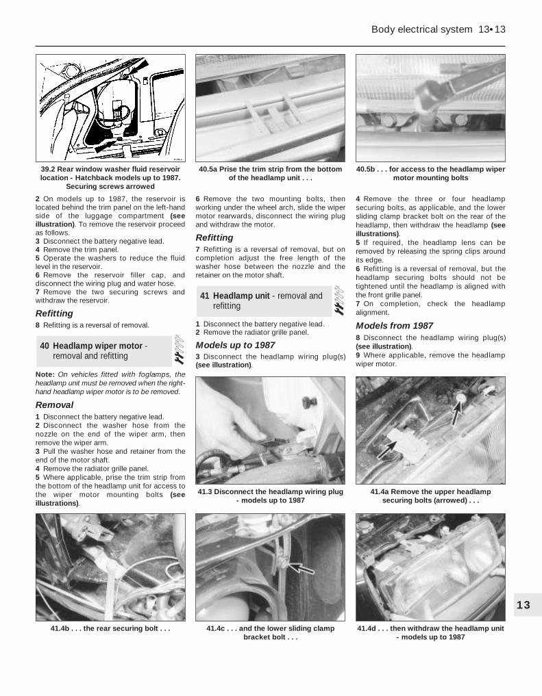
Note: On vehicles fitted with foglamps, theheadlamp unit must be removed when the right-hand headlamp wiper motor is to be removed.
Removal1 Disconnect the battery negative lead. 2 Disconnect the washer hose from thenozzle on the end of the wiper arm, thenremove the wiper arm. 3 Pull the washer hose and retainer from theend of the motor shaft. 4 Remove the radiator grille panel. 5 Where applicable, prise the trim strip fromthe bottom of the headlamp unit for access tothe wiper motor mounting bolts (seeillustrations).
6 Remove the two mounting bolts, thenworking under the wheel arch, slide the wipermotor rearwards, disconnect the wiring plugand withdraw the motor.
Refitting7 Refitting is a reversal of removal, but oncompletion adjust the free length of thewasher hose between the nozzle and theretainer on the motor shaft.
1 Disconnect the battery negative lead. 2 Remove the radiator grille panel.
Models up to 19873 Disconnect the headlamp wiring plug(s)(see illustration).
4 Remove the three or four headlampsecuring bolts, as applicable, and the lowersliding clamp bracket bolt on the rear of theheadlamp, then withdraw the headlamp (seeillustrations).5 If required, the headlamp lens can beremoved by releasing the spring clips aroundits edge.6 Refitting is a reversal of removal, but theheadlamp securing bolts should not betightened until the headlamp is aligned withthe front grille panel.7 On completion, check the headlampalignment.
Models from 19878 Disconnect the headlamp wiring plug(s)(see illustration).9 Where applicable, remove the headlampwiper motor.
41 Headlamp unit - removal andrefitting
40 Headlamp wiper motor -removal and refitting
Body electrical system 13•13
13
40.5b . . . for access to the headlamp wipermotor mounting bolts
41.4d . . . then withdraw the headlamp unit- models up to 1987
41.4c . . . and the lower sliding clampbracket bolt . . .
41.4b . . . the rear securing bolt . . .
41.4a Remove the upper headlampsecuring bolts (arrowed) . . .
41.3 Disconnect the headlamp wiring plug- models up to 1987
40.5a Prise the trim strip from the bottomof the headlamp unit . . .
39.2 Rear window washer fluid reservoirlocation - Hatchback models up to 1987.
Securing screws arrowed

10 Remove the headlamp securing bolt andthe two nuts, then release the anchor springand withdraw the direction indicator !amp unit(see illustrations).11 Pull the headlamp forwards, then swivel itand remove it sideways. 12 If required, the headlamp lens can beremoved by releasing the spring clips aroundits edge.13 Refitting is a reversal of removal.14 On completion, check the headlampalignment.
1 It is recommended that the headlampalignment is carried out by a Ford dealer usingspecialist beam setting equipment. However,in an emergency the following procedure willprovide an acceptable light pattern.2 With the vehicle unladen, with a full tank offuel, and with the tyres correctly inflated,position the vehicle approximately 10 metres
(33 feet) in front of, and at right-angles to, awall or garage door.3 Draw a vertical line on the wallcorresponding to the centre line of the car.The position of the line can be ascertained bymarking the centre of the front and rearscreens with crayon then viewing the wallfrom the rear of the car.4 Complete the lines shown (seeillustration).5 Switch the headlamps on dipped beam andadjust them as necessary using the knobslocated behind the headlamps (seeillustration). Cover the headlamp not beingchecked with cloth.
1 Disconnect the battery negative lead.
Saloon and Hatchback models2 Working inside the luggage compartment,press the plastic retaining tab and remove the
bulbholder assembly.3 Disconnect the wiring plug from thebulbholder.4 Unscrew the securing nuts, and withdrawthe rear lamp unit from outside the vehicle.Recover the gasket.5 Refitting is a reversal of removal.
Estate models6 Working inside the luggage compartment,turn the retaining tabs a quarter-turn andremove the rear side trim panel cover.7 Push out the retaining tabs and withdrawthe bulbholder. 8 Disconnect the wiring plug from thebulbholder.9 Unscrew the four securing nuts, andwithdraw the rear lamp unit from outside thevehicle. Recover the gasket.10 Refitting is a reversal of removal.
43 Rear lamp unit - removal andrefitting
42 Headlamps - alignment
13•14 Body electrical system
41.8 Disconnect the headlamp wiring plug- models from 1987
41.10b . . . the upper securing nut . . .
42.5 Adjusting the headlamp alignment
42.4 Headlamp alignment chart
A Distance between headlamp centresB Light/dark boundaryC Centre of dipped beamD Dipped beam pattern
H Height of headlamp centre from groundX = 160.0 mm (6.3 in) for all models up to 1987
120.0 mm (4.7 in) for all models from 1987
41.10c . . . and the side securing nut -models from 1987
41.10a Remove the headlamp rearsecuring bolt . . .

P100 models11 Remove the two securing screws anddetach the rear lamp wiring cover from theside of the cargo area (see illustration).12 Working through the cargo area aperture,unscrew the two wing nuts and remove therear lamp cover.13 Disconnect the wiring plug from the backof the lamp unit.14 Unscrew the four securing nuts andwithdraw the lamp unit from outside the cargoarea. Recover the gasket.15 Refitting is a reversal of removal, butensure that the plastic washer between thewiring plug and the lamp unit is seatedcorrectly, and make sure that the wiringprotective sheath is seated correctly in theopening in the lamp cover.
1 Disconnect the battery negative lead.
Models up to 1987
Low specification2 Push the lamp unit rearwards into thebumper until the plastic retaining tang is heardto click in the locked position.3 Withdraw the lamp unit from the front of thebumper and disconnect the wiring plug (seeillustration).4 Commence refitting by reconnecting thewiring plug.5 Release the retaining tang, then refit thelamp unit to the bumper, ensuring that thepivot on the lamp unit engages with the slot inthe bumper. Reconnect the battery.
High specification6 Press the release lever at the top of thelamp unit upwards, and withdraw the unitfrom the bumper. Disconnect the wiring plug.7 To refit, reconnect the wiring plug, thenpush the lamp unit into the bumper until itlocates securely. Reconnect the battery.
All models from 19878 Working in the engine compartment,unhook the lamp unit anchor spring from its
anchorage next to the headlamp, thenwithdraw the lamp unit sideways from itsrecess (see illustrations). Disconnect thebulbholder by twisting it anti-clockwise.9 Refitting is a reversal of removal, but ensurethat the locating pins on the lamp unit engagewith the corresponding holes in the headlampmounting panel.
1 Disconnect the battery negative lead.
Models up to 1987 2 To improve access, turn the steering ontofull lock. 3 Remove the relevant wheel arch liner.4 Working under the wheel arch, depress theretaining tabs and withdraw the lamp throughthe outside of the wing (see illustration).Disconnect the bulbholder by twisting it anti-clockwise. 5 Refitting is a reversal of removal.
Models from 1987 6 To improve access, turn the steering ontofull lock. 7 Working in the engine compartment,disconnect the wiring plug. 8 Remove the relevant wheel arch liner.9 Working under the wheel arch, twist thelamp clockwise and withdraw it through the
outside of the wing. Feed the wiring throughthe holes in the wing panels. 10 Refitting is a reversal of removal.
1 Disconnect the battery negative lead.
Models up to 19872 Remove the relevant front directionindicator lamp unit.3 Release the retaining catch on the insideedge of the lamp, then withdraw the lampfrom the bumper and disconnect the wiringplug (see illustration).4 Refitting is a reversal of removal.
46 Front foglamps - removal andrefitting
45 Front direction indicator siderepeater lamp - removal andrefitting
44 Front direction indicatorlamp unit - removal andrefitting
Body electrical system 13•15
13
44.8a Unhook the front direction indicatorlamp unit anchor spring . . .
46.3 Front foglamp removal - models up to 1987A Retaining catch
45.4 Withdrawing a front directionindicator side repeater lamp -
models up to 1987
44.8b . . . and withdraw the lamp unit
44.3 Withdrawing a front directionindicator lamp unit - “low specification”
models up to 1987
43.11 Rear lamp wiring cover (A) and rearlamp cover (B) - P100 models

Models from 19875 Remove the two securing screws, thenwithdraw the lamp forwards and disconnectthe two wiring plugs.6 Refitting is a reversal of removal, but wherenecessary use a new gasket between thelamp and bumper.7 On completion, the vertical alignment of thefoglamp must be adjusted. For the foglamps,dimension “X” (see illustration, 42.4) shouldbe taken as 220.0 mm (8.7 in). The adjusterscrew is located on the inside edge of thelamp above the securing screw (seeillustration).
1 Disconnect the battery negative lead.
Saloon, Hatchback and Estatemodels2 To remove a lamp, simply prise it from thebumper using a thin-bladed screwdriver, anddisconnect the wiring plug (see illustration).3 Refitting is a reversal of removal.
P100 models4 Working behind the rear crossmember, pullthe wiring plug from its clip and disconnect it.5 Pull the lamp cover from the rubberhousing, then pull the rubber housing and thewiring from the crossmember. 6 Refitting is a reversal of removal.
Note: The glass envelopes of the headlamp,auxiliary driving lamp and front foglamp bulbsmust not be touched with the fingers. If theglass is accidentally touched, it should bewashed with methylated spirits and dried witha soft cloth. Failure to observe this proceduremay result in premature bulb failure.1 Disconnect the battery negative lead.
Headlamps2 Working in the engine compartment,remove the headlamp rear cover by turning itanti-clockwise (see illustration).
3 Pull the wiring plug from the base of thebulb, then release the spring clip, grasp thebulb by its contacts and carefully withdraw it(see illustrations). Do not touch the bulbglass.4 Refitting is a reversal of removal, but onmodels up to 1987, refit the headlamp rearcover by aligning the arrow on the cover withthe depression on the top of the headlampunit and turning the cover clockwise until thearrow aligns with the lower depression. Onmodels from 1987, the word “OBEN “ or“TOP” on the rear cover should be exactly atthe top after refitting.
Sidelamps5 Working in the engine compartment,remove the headlamp rear cover by turning itanti-clockwise.6 Pull the sidelamp bulbholder from itslocation in the headlamp reflector (see
illustration). On “high specification” modelsup to 1987 a retaining tab must be depressedbefore withdrawing the bulbholder. Note thatthe rubber sleeve should be left in position inthe reflector.7 Refitting is as described in paragraph 4.
Auxiliary driving lamps
Models up to 19878 Twist the cover on the top of the headlampunit anti-clockwise and remove it to exposethe bulb (see illustration).9 Release the bulb from the two clips, thendisconnect the wiring and remove the bulb.Do not touch the bulb glass (see illustration).10 Refitting is a reversal of removal.
Models from 198711 Release the spring clip securing the coverto the rear of the headlamp unit, then removethe cover (see illustration).
48 Exterior lamp bulbs - renewal
47 Rear number plate lamp -removal and refitting
13•16 Body electrical system
46.7 Front foglamp adjuster screw (A) andsecuring screws (B) - models from 1987
48.2 Remove the headlamp rear cover
48.8 Auxiliary drive lamp bulb cover(arrowed) - models up to 1987
48.6 Removing a sidelamp bulbholder48.3b Release the spring clip and withdrawthe headlamp bulb
48.3a Pull off the wiring plug . . .
47.2 Removing a rear number plate lamp -Saloon, Hatchback and Estate models

12 Disconnect the wiring from the bulb, thenrelease the spring clip and withdraw the bulb.Do not touch the bulb glass.13 Refitting is a reversal of removal.
Front direction indicator lamps
Models up to 198714 Remove the lamp unit.15 Twist the bulbholder anti-clockwise andwithdraw it from the rear of the lamp. The bulbis a bayonet fit in the bulbholder (seeillustration).16 Refitting is a reversal of removal.
Models from 1987 17 Remove the lamp unit.18 Release the bulbholder by pressing it andturning clockwise, then withdraw the bulbfrom the bulbholder (see illustration).19 Refitting is a reversal of removal.
Front direction indicator siderepeater lamps
Models up to 198720 To improve access, turn the steering ontofull lock.21 Remove the relevant wheel arch liner.22 Working under the wheel arch, twist thebulbholder anti-clockwise and withdraw itfrom the lamp. The bulb is a push-fit in thebulbholder. 23 Refitting is a reversal of removal.
Models from 1987 24 Remove the lamp unit.
25 Twist the bulbholder anti-clockwise toremove it from the lamp. The bulb is a push-fitin the bulbholder. 26 Refitting is a reversal of removal.
Front foglamps 27 Remove the foglamp. 28 On models up to 1987, remove the bulbcover from the rear of the lamp, then releasethe two spring clips, disconnect the wiring andwithdraw the bulb. Do not touch the bulb glass. 29 On models from 1987, release the springclip and pull the bulb from the bulbholder. Donot touch the bulb glass (see illustration). 30 Refitting is a reversal of removal.
Rear lamp unit
Saloon and Hatchback models 31 Working inside the luggage compartment,press the plastic retaining tab and remove thebulbholder assembly. The bulbs are a bayonetfit in the bulbholder (see illustrations). 32 Refitting is a reversal of removal.
Estate models 33 Working inside the luggage compartment,turn the retaining tabs a quarter-turn andremove the rear side trim panel cover. 34 Push out the retaining tabs and withdrawthe bulbholder. The bulbs are a bayonet fit inthe bulbholder. 35 Refitting is a reversal of removal.
P100 models 36 Remove the two securing screws anddetach the rear lamp wiring cover from theside of the cargo area.
37 Working through the cargo area aperture,unscrew the two wing nuts and remove therear lamp cover. 38 Twist the relevant bulbholder anti-clockwise to remove it from the lamp. Thebulb is a bayonet fit in the bulbholder. 39 Refitting is a reversal of removal, butensure that the wiring protective sheath isseated correctly in the opening in the lampcover.
Rear number plate lamp
Saloon, Hatchback and Estate models 40 Remove the lamp unit. 41 Twist the bulbholder anti-clockwise toremove it from the lamp. The bulb is a push-fitin the bulbholder (see illustration). 42 Refitting is a reversal of removal.
Body electrical system 13•17
13
48.15 Removing a front direction indicatorlamp bulb - models up to 1987
48.31b Removing a bulb from the rear lampbulbholder - Saloon and Hatchback
models
48.31a Press the plastic retaining tab torelease the rear lamp bulbholder assembly
- Saloon and Hatchback models
48.29 Front foglamp bulb retaining springclip - models from 1987
48.18 Removing a front direction indicatorlamp bulb - models from 1987
48.11 Auxiliary driving lamp bulb location -models from 1987
48.9 Withdraw the auxiliary driving lampbulb from the headlamp unit -
models up to 1987

P100 models 43 Pull the lamp cover from the rubberhousing to expose the bulb. The bulb is abayonet fitting in the bulbholder. 44 Refitting is a reversal of removal.
1 Disconnect the battery negative lead.
Switches 2 Prise the switch from its location using athin-bladed screwdriver, and disconnect thewiring plug (see illustration). 3 Refitting is a reversal of removal.
Operating motors 4 Remove the window regulator. 5 Remove the three securing bolts, andwithdraw the motor from the regulatorassembly (see illustration). 6 Refitting is a reversal of removal, but ensurethat the drive gear is correctly meshed withthe regulator.
Note: If a central locking solenoid or motor isto be renewed due to jamming or overheating,the central locking relay must be renewed at
the same time even if it is believed to beworking correctly. Before starting work on thecentral locking system, unlock all the doorsand the tailgate/boot. Make sure that the keysare outside the vehicle before reconnectingthe battery on completion of work.
Operation
Models up to 19871 The central locking system is activated byturning the key in the driver’s door lock, andthe locks are operated by solenoids.
Models from 19872 The system is activated by turning the keyin either of the front door locks, and the locksare operated by electric motors.
Removal and refitting3 Disconnect the battery negative lead.
Models up to 1987Switch (driver’s door lock)4 Remove the door lock.5 Remove the two securing screws, thenwithdraw the switch from the lock assemblyand disconnect the wiring plug.6 Refitting is a reversal of removal, but ensurethat the cut-out in the switch lever engageswith the lock lever (see illustration).Solenoids (passenger and rear door locks)7 Remove the door lock (see illustration).8 Remove the two securing screws, thendisconnect the solenoid operating rod and the
wiring plug and withdraw the solenoid fromthe lock assembly.9 Refitting is a reversal of removal. Solenoid (tailgate lock)10 Open the tailgate and remove the trimpanel.11 Disconnect the solenoid wiring plug andearth lead, and the operating rod, thenremove the two securing screws andwithdraw the solenoid from the tailgate (seeillustration).12 Refitting is a reversal of removal.
Models from 1987 Motors (door locks)13 Remove the door inner trim panel.14 Remove the retaining screws anddisconnect the wiring plug and the motoroperating rod, then withdraw the motor fromthe door.15 Refitting is a reversal of removal.Motor (tailgate and boot lid locks)16 Open the tailgate/boot lid and whereapplicable remove the trim panel.17 Remove the retaining screws anddisconnect the wiring plug and the motoroperating rod, then withdraw the motor fromthe tailgate/boot.18 Refitting is a reversal of removal.
Models from 1990Motors (door locking)19 On models from 1990, the door lockingmotors are incorporated in the door lock units(see illustrations).20 To remove a motor, first remove the doorlock.
50 Central door lockingcomponents - operation,removal and refitting
49 Electric window components- removal and refitting
13•18 Body electrical system
48.41 Removing a rear number plate lampbulb - Saloon, Hatchback and Estate
models
49.5 Electric window motor securing bolts(arrowed)
50.7 Central door locking assembly -models up to 1987
A SolenoidB Door ajar switch (not fitted to all models)
50.6 Driver’s door central locking switch -models up to 1987
A Switch lever cut-out
49.2 Disconnecting the wiring plug from acentre console-mounted electric window
switch - models from 1987
50.11 Removing a tailgate lock solenoid -Hatchback models up to 1987

21 Remove the two securing screws, anddetach the motor from the lock assembly.22 Refitting is a reversal of removal, ensuringthat the motor operating rod engages with thelock lever.
Note: The alarm system has a self-diagnosisfunction, which allows a Ford dealer to carryout fault diagnosis, using suitable specialistequipment. In the event of a problem with thealarm system, it is advisable not to tamperwith the components until appropriate faultdiagnosis has been carried out.
Location1 From 1990, certain models are fitted withan anti-theft alarm (see illustration).2 The alarm system consists of a controlmodule mounted behind the driver’s sidefacia; trip switches fitted to the doors,tailgate/boot lid, and bonnet; activatingswitches fitted to the front door locks; anadditional horn mounted at the bulkhead nextto the battery and an indicator light mountedon the top of the facia.
Module - removal and refitting 3 Disconnect the battery negative lead. 4 Release the carpet trim panel from underthe driver’s side facia.
5 Reach up behind the facia and locate thecontrol module. Release the plastic retainingclips using a screwdriver, and lower themodule. 6 Disconnect the wiring plug and withdrawthe module. 7 Refitting is a reversal of removal.
Removal1 Disconnect the battery negative lead.2 Remove the seat.3 Remove the seat cushion trim or backresttrim as necessary.4 Note which way round the pad is fitted,then remove the wire clips and adhesive tapewhich secure it to the seat. Retrieve the tie-rod and fit it to the new pad.
Refitting5 Fit the new pad with the thermostat facingthe cushion foam (see illustration). Securethe pad with wire clips and tape, making surethat it is not too tight - it must be able to flexwhen sat on.6 Refit the cushion or backrest trim, asapplicable, being careful not to trap or kinkthe pad.7 Refit the seat, reconnect the wiring andcheck the pads for correct operation.
52 Seat heating pad - removaland refitting
51 Anti-theft alarm - location,removal and refitting
Body electrical system 13•19
13
50.19b Rear door central locking motorsecuring screws (arrowed) -
models from 1990
50.19a Front door central locking motorsecuring screws (arrowed) -
models from 1990
51.1 Anti-theft alarmsystem components
A Tailgate/boot lidswitch
B Control moduleC HornD Bonnet switchE Door switchF Activating switch

1 On models fitted with an electric aerial,disconnect the battery negative lead.
Saloon and Estate models2 Remove the right-hand side trim panel fromthe luggage compartment.3 Working outside the vehicle, unscrew thenut and remove the spacer and seal from thebase of the aerial.4 Working inside the luggage compartment,either unscrew the aerial bracket securingscrew and slide the bracket from the aerialtube, or pull the base of the aerial from therubber bush in the bracket, as applicable (seeillustration).5 Ensure that the aerial is fully retracted, thenpull it through the hole in the bodywork intothe luggage compartment (see illustration).6 The aerial lead may be a push-fit in thebase of the aerial, or may be secured by aknurled nut. Disconnect the aerial lead andwhere applicable, disconnect the wiring fromthe electric motor. Note that the aerial leadruns through the roof. If it is necessary torenew the lead, it may prove easier to leavethe old lead in place and run a new one underthe carpet. Follow existing wiring runs wherepossible.7 Refitting is a reversal of removal.
Hatchback models8 Remove the right-hand rear seat sidecushion.9 Remove the rear parcel shelf.10 On “high specification” models, lift theseat catch release lever, push out the pinsecuring the link rod to the lever anddisconnect the link rod.11 Remove the securing screws from the rearparcel shelf support (nine screws on modelsup to 1987, eight screws from 1987 onwards).Remove the rear parcel shelf support.12 Remove the side trim panel from theluggage compartment.13 Proceed as described in paragraphs 3 to7 inclusive.
P100 models14 Pull off the plastic trim cover and unscrewthe aerial securing nut. 15 Withdraw the aerial assembly, andcarefully prise the base seal from the roofpanel.16 The aerial lead runs across the roof panelunder the headlining, and down the right-handfront pillar to the radio unit. Renewal isstraightforward, but the front section of theheadlining must be released for access and alength of string should be tied to the end ofthe aerial lead before removal to aid routingwhen refitting. 17 The aerial rod can be renewed by simplyunscrewing it from the base. 18 Refitting is a reversal of removal.
1 Disconnect the battery negative lead.
Saloon models 2 Remove both rear seat side cushions. 3 Remove the securing screws and withdrawthe rear parcel shelf.4 Make a note of the wiring connections foruse when refitting, then disconnect the wiring,remove the two securing screws, andwithdraw the amplifier unit (see illustration). 5 Refitting is a reversal of removal.
Hatchback models 6 Unclip the tailgate trim panel. 7 Remove the amplifier bracket securingscrews, and withdraw the amplifier throughthe tailgate panel aperture (see illustration).8 Make a note of the wiring connections foruse when refitting, then disconnect the wiringand remove the amplifier unit. 9 Refitting is a reversal of removal.
Estate models10 Unclip the tailgate trim panel.11 Make a note of the wiring connections foruse when refitting, then disconnect the wiring,remove the four securing screws, and detachthe loudspeaker/amplifier bracket assemblyfrom the tailgate (see illustration).12 Refitting is a reversal of removal.
1 Disconnect the battery earth lead.
Facia panel-mounted speakers
Upper 2 Prise the speaker grille from its fourretaining clips in the facia using a thin-bladedscrewdriver.3 Remove the four securing screws,disconnect the wiring, and pull theloudspeaker from the facia panel. 4 Refitting is a reversal of removal.
55 Loudspeakers - removal andrefitting
54 Integral heated rearwindow/radio aerial amplifier- removal and refitting
53 Radio aerial (exterior-mounted) - removal andrefitting
13•20 Body electrical system
52.5 Seat heating pad
Thermostat (arrowed) must face foam
53.5 Removing an electric aerial - Saloon model
54.7 Integral heated rear window/radioaerial amplifier bracket securing screws
(arrowed) - Hatchback models
54.4 Integral heated rear window/radioaerial amplifier securing screws (arrowed)
- Saloon models
53.4 Pull the base of the aerial from therubber bush (arrowed)

Lower5 Remove the lower facia panel.6 Remove the four securing screws,disconnect the wiring, and pull theloudspeaker from the facia panel. 7 Refitting is a reversal of removal.
Rear parcel shelf-mountedspeakers
Saloon models8 Working in the luggage compartment,remove the single securing screw, then lift theloudspeaker into the passenger compartmentand disconnect the wiring. Withdraw theloudspeaker.9 Note that it is important not to disturb theloudspeaker mounting gasket or retainer.10 Refitting is a reversal of removal, butensure that the wiring does not touch theretainer, shelf, or speaker, to prevent anyaudible rattles.
Hatchback models11 Working under the parcel shelf, removethe four securing screws, disconnect thewiring, and withdraw the loudspeaker.12 Refitting is a reversal of removal.
Door-mounted speakers13 Remove the door inner trim panel.14 Remove the four securing screws, thenwithdraw the loudspeaker from the door anddisconnect the wiring. Remove theloudspeaker.15 Do not remove the loudspeaker from themoulding, as the two are a sealed assembly.16 Refitting is a reversal of removal.
Tailgate-mounted speakers -Estate models17 Remove the tailgate trim panel.18 Remove the four securing screws,disconnect the wiring and withdraw theloudspeaker. Note that on models with anintegral heated rear window/radio aerial, theaerial amplifier unit is combined with one ofthe loudspeaker units.
19 Refitting is a reversal of removal.
High frequency units20 These units are used to reproduce highfrequencies only, and incorporate anelectronic filter network which must not bedisconnected or bypassed. The units arelocated in the lower facia panels.21 The removal and refitting procedure is asdescribed for the lower facia panel-mountedloudspeakers earlier in this Section, but takecare not to damage the extremely fragilespeaker cones.
Removal1 Some “high specification” models are fittedwith an audio power amplifier, which ismounted as a separate unit beneath the radio/cassette unit. To remove the unit proceed asfollows.2 Disconnect the battery negative lead.3 Remove the two screws under the top edgeof the power amplifier unit.4 Slide the unit forwards from the facia panel,until the wiring plugs can be disconnected.Disconnect the wiring plugs and remove theunit.
Refitting5 Refitting is a reversal of removal.
Standard fixing 1 Disconnect the battery negative lead.2 Pull off the two control knob assemblies.3 Release the trim panel by unscrewing thetwo securing nuts from the control spindles.Remove the trim panel.
4 Using a hooked instrument, pull themounting plate securing tangs towards thecentre of the radio/cassette player, then slidethe unit forwards from the facia panel (seeillustration).5 Disconnect the wiring plugs and the aeriallead, then remove the unit.6 Remove the plastic support bracket fromthe rear of the unit, and unscrew the nuts andwashers from the control spindles to removethe mounting plate from the front of the unit.7 Refitting is a reversal of removal.
DIN fixing8 An increasing number of radio/cassetteplayers have DIN standard fixings. Twospecial tools, obtainable from in-carentertainment specialists, are required forremoval.9 Disconnect the battery negative lead.10 Insert the tools into the holes in the frontof the radio/cassette player and push themuntil they snap into place. Pull the toolsoutwards to release the unit (see illustration).11 Pull the unit forwards and disconnect thewiring plugs and the aerial lead. Remove theunit from the facia panel.12 To refit the radio/cassette player,reconnect the wiring and the aerial lead, thensimply push the unit into its bracket until theretaining lugs snap into place.
Each wiring diagram covers a particularsystem of the appropriate vehicle; asindicated in each caption. Carefully read theKey to each diagram before commencingwork.
58 Wiring diagrams - generalinformation
57 Radio/cassette player -removal and refitting
56 Radio/cassette player poweramplifier - removal andrefitting
Body electrical system 13•21
13
57.10 Removing a radio/cassette playerusing special tools - DIN fixing
57.4 Radio/cassette player securing tangs(arrowed) viewed from the rear of the unit -
standard fixing
54.11 Loudspeaker/integral heated rearwindow/radio aerial amplifier bracket
securing screws (arrowed) - Estate models

13•22 Wiring diagrams
Notes, tables, wire colours and key to wiring diagrams. Models up to 1987

13
Wiring diagrams 13•23
Key to wiring diagrams (continued). Models up to 1987

13•24 Wiring diagrams
Internal connection details. Models up to 1987
Klo
cka

Wiring diagrams 13•25
13
Internal connection details (continued). Models up to 1987