chapter 15 development and testing of a remote …€¦ · chapter 15 development and testing of a...
TRANSCRIPT
171
Chapter 15
Development and Testing of a Remote Access MEMS Lab for Distance Education GAUTHAM RAMACHANDRAN, ASHWIN VIJAYASAI, GABRIEL RAMIREZ, AND TIM DALLAS Texas Tech University, Electrical and Computer Engineering, Lubbock, TX 79409, USA. E-mail: [email protected]
Advancements in cyber communications are making an impact on the delivery of education by opening up new modes of interaction. Microelectromechanical Systems (MEMS) based technologies provide a compelling way to extend the benefits of interactive experimentation to students being taught through distance education. In this work, a remotely accessible MEMS laboratory, physically located at Texas Tech University, was developed and tested. The laboratory is comprised of a MEMS chip containing an array of micro-actuators, a digital microscope, a motorized stage, and software that permits remote control and viewing. To conduct a lab, a student logs into the server, selects a device to operate and experiment with, and follows procedures contained in a lab manual. The video feed from the digital microscope is embedded into a live streaming server allowing the student to quantify the motion of the dynamic MEMS devices. The system has been utilized as an instrumental part in the MEMS 1 curriculum at Texas Tech University.
INTRODUCTION
The development of remote laboratories has been fueled by a number of factors, but the primary motivation has been to provide utilization of laboratory tools to more people for greater amounts of time. Expensive characterization tools, such as SEM (scanning electron microscope) and AFM (atomic force microscope) have been put on-line by institutions, such as Pennsylvania State University [1] and North Dakota State University [2], to allow students and researchers at other institutions to gain access to systems that their home institutions do not own. This mode of operation has been the norm for many years in the realm of astronomy wherein telescopes are made available to various remote clients for fixed periods of time. Large travel costs are avoided while broader utilization is achieved.
INNOVATIONS 2012 172
Researchers have developed remotely accessible labs including basic electronic engineering labs wherein students can make a simple measurement such as diode forward biased characteristics [3]. Others are using remote access tools for characterization using a scanning electron microscope [4]. A common denominator of most remote access systems has been the use of National Instruments (NI) LabVIEW software [5] for providing remote access to control the system and sometimes viewing. Krehbiel et al. [6] proposed a remote lab using LabVIEW control software for teaching concepts in environmental and ecological sciences. The system consisted of a Linux Web server running LabVIEW, AppletVIEW, Apache Web Server and Darwin Video Server connected to multiple data acquisition computers. Yayla et al. [7] utilized LabVIEW to teach concepts in digital and analog communication by interfacing instruments consisting of GPIB controllable devices. Kutlu et al. [8] interfaced a Controller Area Network with many different experimental setups using LabVIEW as the control software. Gontean et al. [9] used NI’s PCI eXtensions for Instrumentation (PXI) to establish a remote lab to perform experiments such as motor control. These examples illustrate the breadth of functionality provided by the LabVIEW tools.
The field of MEMS is a prime opportunity to take advantage of the inherent nature of the devices for remote experiments for both education and research. Typically, MEMS devices are classified as either sensors or actuators. MEMS sensors include accelerometers, gyroscopes, and pressure sensors that are found in a wide range of consumer products. Actuators include micromirrors and varactors that are integral parts of video display systems and communication tools, respectively. These chip based devices are on the order of millimeters in size with most features of the devices on the micrometer scale. To view the motion of the dynamic devices, a microscope is required. By using a microscope equipped with a digital video camera, the motion can be viewed through a display adjacent to the experiment or sent through the internet to users anywhere.
Our current results extend the work of previous MEMS-based remote laboratories. Diong et al. [10] developed a remote lab for experiments on a MEMS device. They used an NI Educational Laboratory Virtual Instrumentation Suite (ELVIS) unit, which can be directly interfaced to LabVIEW to power the MEMS device. The image acquisition was done using a LabVIEW compatible IMAQ PCI-1405 board. They captured an image of the device at the peak voltage and set that image as the “powered image.” The student compared the difference between the “powered image” and the “unpowered image” to make displacement measurements. Meanwhile, the voltage is turned to zero to reduce the thermal stress to the device so the experimenter could take some time to actually measure the displacement. Whereas, Sivakumar et al. [11] developed a Teleoperated MEMS Lab using a Linux based server to a view and control a MEMS device remotely. They incorporated an Apache Web Server to control the LabVIEW application that was used to control the device. Another version of the remote MEMS lab by Sivakumar et al. [12] interfaced a haptic device that allowed tactile feedback to the user as they controlled the power to the device.
REMOTE LAB COMPONENTS
In this section, we discuss the hardware and software components that were utilized in the current generation of the remote access lab. Our set-up utilized components available in our lab including:
INNOVATIONS 2012 173
Motorized XY Stage (Newport Corp.) ESP 300 Motion Controller/Driver (Newport Corp.) MEMS Power Supply (Class on a Chip, Inc.) MEMS Chip (Class on a Chip, Inc.) USB microscope (Dino Lite, 500X fixed magnification)
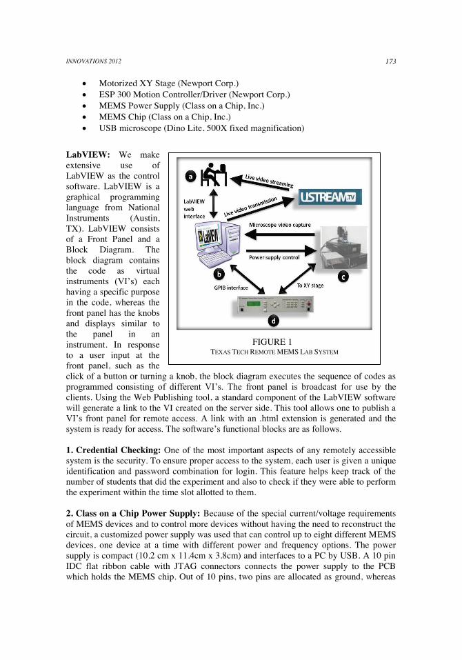
LabVIEW: We make extensive use of LabVIEW as the control software. LabVIEW is a graphical programming language from National Instruments (Austin, TX). LabVIEW consists of a Front Panel and a Block Diagram. The block diagram contains the code as virtual instruments (VI’s) each having a specific purpose in the code, whereas the front panel has the knobs and displays similar to the panel in an instrument. In response to a user input at the front panel, such as the click of a button or turning a knob, the block diagram executes the sequence of codes as programmed consisting of different VI’s. The front panel is broadcast for use by the clients. Using the Web Publishing tool, a standard component of the LabVIEW software will generate a link to the VI created on the server side. This tool allows one to publish a VI’s front panel for remote access. A link with an .html extension is generated and the system is ready for access. The software’s functional blocks are as follows.
1. Credential Checking: One of the most important aspects of any remotely accessible system is the security. To ensure proper access to the system, each user is given a unique identification and password combination for login. This feature helps keep track of the number of students that did the experiment and also to check if they were able to perform the experiment within the time slot allotted to them.
2. Class on a Chip Power Supply: Because of the special current/voltage requirements of MEMS devices and to control more devices without having the need to reconstruct the circuit, a customized power supply was used that can control up to eight different MEMS devices, one device at a time with different power and frequency options. The power supply is compact (10.2 cm x 11.4cm x 3.8cm) and interfaces to a PC by USB. A 10 pin IDC flat ribbon cable with JTAG connectors connects the power supply to the PCB which holds the MEMS chip. Out of 10 pins, two pins are allocated as ground, whereas
FIGURE 1
TEXAS TECH REMOTE MEMS LAB SYSTEM

INNOVATIONS 2012 174
FIGURE 2
TOP VIEW OF DIFFERENT DEVICES PRESENT
ON THE MEMS CHIP
FIGURE 3 DIFFERENT MENUS AVAILABLE TO THE USER (a) HOME WINDOW/SIDE SELECTION WINDOW (b) DEVICE SELECTION WINDOW (c) POWER SUPPLY CONTROL WINDOW
ports 0-5 are electrothermal device ports and ports 6-7 are electrostatic device ports with higher voltages. LabVIEW software is used to control the power supply by communicating with the microcontroller on the power supply board and the computer. 3. Positioner and Controller: In order to perform experiments on multiple devices sequentially, the chip has to be precisely repositioned under the microscope. The MEMS chip is placed on the computer controlled two-axis stage. The controller’s GPIB port is interfaced to the server computer using a GPIB to PCI card from NI. The LabVIEW drivers (VI’s) are built and the position of each MEMS device relative to the stage home (0, 0) is given as input, corresponding to the device selection made. The coordinate location of the devices are determined manually and fed to the program allowing LabVIEW to position the stage when a user selects a particular device. MEMS Chip: The MEMS chip used in the system is fabricated using the SUMMiT-V process; a five-layer, polycrystalline silicon surface micromachining process. The devices are designed using AutoCAD and the chip is fabricated at Sandia National Laboratories (Albuquerque, NM). The chips are packaged in a 48 pin DIP with a glass lid to view the device and to prevent dust particles and varying humidity from ruining the movable MEMS parts. The chip is approximately 6mm x 3mm and contains 20-25 devices. Many of the devices are used by the students to perform experiments from the lab manual. The chip being used currently has a choice of electrothermal actuators, electrostatic comb-drives, micromotors, and micromirrors. Microscope/Video Feed: Initially, a CCD camera and LabVIEW IMAQ VI’s [13] were used for capturing the video feed

INNOVATIONS 2012
175
FIGURE 4 BROADCAST FRONT PANEL FOR
SAMPLE LAB IN A WEB BROWSER
and transmitting as either a separate link or embed into the control VI. Due to delay issues, alterations were made. For better, faster, and more reliable video transmission through the internet, a USB interfaced AM413T5 Dino-Lite Pro 500X was used to capture the movement of the MEMS devices. To ensure a satisfactory video feed to the client instead of loading the server at Texas Tech with many users, an alternative method was developed in which the video feed is transmitted to a live streaming server in a dedicated channel. The advantage of this method is the load at the Texas Tech server is greatly reduced and there can be multiple viewers. For example, a class with many students can each view the video of these devices while an instructor is controlling the device, analogous to a sports telecast. The video feed channel can be password protected, too. Using the Adobe Flash Media Live Encoder, the data transmitted to the dedicated MEMS channel can be altered. For optimum video transmission, the following parameters in the Adobe Flash Media Live Encoder [14] were used. The parameters were selected based on various conditions such as speed of the internet connection, camera type, etc. The video format used is VP6, the frame rate is 29 fps, and the input size was 800 x 600 pixels. The data is transferred to the “ttumemslab” channel on USTREAM. (http://www.ustream.tv/channel/ttumemslab).
MODES OF OPERATION
Two different modes of operation were developed in this work based on the client type. i. Complete Server: In a complete server that operates with 16 devices, the following configuration is used. The broadcasted front panel is split into Side A and Side B, each consisting of eight devices. This corresponds to the number of device the power supply can be interfaced to at one time. To access both sides, two power supplies, each with its own LabVIEW recognized address, are utilized. As shown in Figure 3, the user first chooses a side and then a device. Clicking on a device causes the device control GUI to appear (c) as the stage positions the device under the microscope. The GUI contains a “chip map” that highlights the device in use. ii. Experiment Mode: In the MEMS I course, students typically use only one device for a particular experiment. In this case, only the particular device VI is broadcast, as shown in Figure 4. In this mode, the single front panel consists of the sign-in details (left side) and the power supply controls (right side). For more details refer to “Sample Lab” section. Client Requirements: A stable internet connection is needed. A plug-in to run/view the LabVIEW GUI is sent to the students performing the experiments along with the lab manual. Alternatively, it can also be downloaded from http://joule.ni.com/nidu/cds/
INNOVATIONS 2012 176
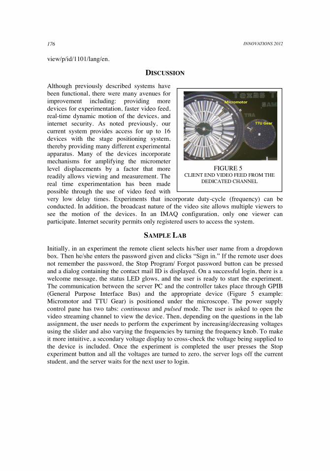
FIGURE 5
CLIENT END VIDEO FEED FROM THE DEDICATED CHANNEL
view/p/id/1101/lang/en.
DISCUSSION
Although previously described systems have been functional, there were many avenues for improvement including: providing more devices for experimentation, faster video feed, real-time dynamic motion of the devices, and internet security. As noted previously, our current system provides access for up to 16 devices with the stage positioning system, thereby providing many different experimental apparatus. Many of the devices incorporate mechanisms for amplifying the micrometer level displacements by a factor that more readily allows viewing and measurement. The real time experimentation has been made possible through the use of video feed with very low delay times. Experiments that incorporate duty-cycle (frequency) can be conducted. In addition, the broadcast nature of the video site allows multiple viewers to see the motion of the devices. In an IMAQ configuration, only one viewer can participate. Internet security permits only registered users to access the system.
SAMPLE LAB
Initially, in an experiment the remote client selects his/her user name from a dropdown box. Then he/she enters the password given and clicks “Sign in.” If the remote user does not remember the password, the Stop Program/ Forgot password button can be pressed and a dialog containing the contact mail ID is displayed. On a successful login, there is a welcome message, the status LED glows, and the user is ready to start the experiment. The communication between the server PC and the controller takes place through GPIB (General Purpose Interface Bus) and the appropriate device (Figure 5 example: Micromotor and TTU Gear) is positioned under the microscope. The power supply control pane has two tabs: continuous and pulsed mode. The user is asked to open the video streaming channel to view the device. Then, depending on the questions in the lab assignment, the user needs to perform the experiment by increasing/decreasing voltages using the slider and also varying the frequencies by turning the frequency knob. To make it more intuitive, a secondary voltage display to cross-check the voltage being supplied to the device is included. Once the experiment is completed the user presses the Stop experiment button and all the voltages are turned to zero, the server logs off the current student, and the server waits for the next user to login.
INNOVATIONS 2012
177
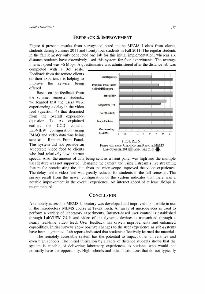
FIGURE 6 FEEDBACK FROM USERS OF THE REMOTE MEMS
LAB-SUMMER 2011(█) AND FALL 2011 (█).
FEEDBACK & IMPROVEMENT
Figure 6 presents results from surveys collected in the MEMS I class from eleven students during Summer 2011 and twenty four students in Fall 2011. The regular students in the fall semester only conducted one lab for this initial implementation, whereas six distance students have extensively used this system for four experiments. The average internet speed was ~6 Mbps. A questionnaire was administered after the distance lab was completed with a 0-5 scale. Feedback from the remote clients on their experience is helping to improve the service being offered.
Based on the feedback from the summer semester students, we learned that the users were experiencing a delay in the video feed (question 4) that detracted from the overall experience (question 7). As explained earlier, the CCD camera-LabVIEW configuration using IMAQ and video data was being sent as a Remote Front Panel. This system did not provide an acceptable video feed to clients who had relatively low internet speeds. Also, the amount of data being sent as a front panel was high and the multiple user feature was not supported. Changing the camera and using Ustream’s live streaming feature for broadcasting the data from the microscope improved the video experience. The delay in the video feed was greatly reduced for students in the fall semester. The survey result from the newer configuration of the system indicates that there was a notable improvement in the overall experience. An internet speed of at least 3Mbps is recommended.
CONCLUSION
A remotely accessible MEMS laboratory was developed and improved upon while in use in the introductory MEMS course at Texas Tech. An array of microdevices is used to perform a variety of laboratory experiments. Internet-based user control is established through LabVIEW GUIs and video of the dynamic devices is transmitted through a nearly real-time video feed. User feedback has driven improvements and enhanced capabilities. Initial surveys show positive changes to the user experience as sub-systems have been augmented. Lab reports indicated that students effectively learned the material.
The remotely accessible system has the potential to impact other universities and even high schools. The initial utilization by a cadre of distance students shows that the system is capable of delivering laboratory experiences to students who would not normally have the opportunity. High schools and other institutions that do not typically

INNOVATIONS 2012 178
own sophisticated micro/nano tools could acquire access to interesting and captivating laboratory experiences.
ACKNOWLEDGMENTS
The work was supported in part by National Science Foundation grants DUE #0837521 and IIP#1014222 (sub-award).
REFERENCES
1. Education & Careers in Nanotechnology, “Competing in the 21st Century: The
Nanotechnology Edge,” http://www.nano4me.org/industry.html
2. North Dakota State University, “JEOL JSM-6490LV Scanning Electron Microscope,” http://www.ndsu.edu/em_lab/instrumentation/jeoljsm_6490lv/remote_sem_use/.
3. T. A. Fjeldly, M. S. Shur, H. Shen and T. Ytterdal, “AIM-Lab: A System for Remote Characterization of Electronic Devices and Circuits over the Internet,” Proceedings of the 2000 Third IEEE International Caracas Conference on , Circuits, and Systems, pp. I43/1-I43/6, 2000.
4. N. H. M. Caldwell, B. C. Breton, and D. M. Holburn, “Remote Instrument Diagnosis on the Internet,” IEEE: Intelligent Systems and their Applications, vol. 13, pp. 70 – 76, 1998.
5. National Instruments, “LabVIEW System Design Software,” http://www.ni.com/labview
6. D. Krehbiel, R. Zerger, J. K. Piper “Remote-Access LabVIEW-Based Laboratory for Environmental and Ecological Science,” Int. J. Eng. Ed., vol. 19, pp. 495-502, 2003.
7. XA. Yayla, A. Akar, “Web Based Real Time Laboratory Applications of Analog and Digital Communication Courses with LabVIEW Access,” International Journal of Social Sciences, vol. 1, pp. 254-258, 2008.
8. XA. Kutlu and K. Taşdelen, “Remote Electronic Experiments using LabVIEW over Controller Area Network,” Scientific Research and Essays, vol. 5, pp. 1754-1758, 2010.
9. XA. Gontean, R. Szabo, and I. Lie, “LabVIEW Powered Remote Lab,” SIITME 2009 - 15th International Symposium for Design and Tech. of Electronics Packages, pp. 335-340, 2009.
10. B. Diong, J. Smith, E. Kolesar and R. Cote, “Remote Experimentation with MEMS Devices,” Proc. ASEE National Conf., Austin, TX, Jun 2009.
11. G. Sivakumar, M. Mulsow, A. Mellinger, S. Lacouture, and T. Dallas, “Teleoperated Microsystems Laboratory,” Proceedings ASME 2009 International Design Engin. Tech. Conf. & Computers and Information in Eng. Conf., San Diego, CA, 2009.
12. G. Sivakumar, M. Mulsow, A. Melinger, S. Lacouture, and T. E. Dallas, "Remotely Accessible Laboratory for MEMS Testing," in Reliability, Packaging, Testing, and Characterization of Mems/Moems and Nanodevices Ix. vol. 7592, R. C. R. R. Kullberg, Ed., 75920E, 2010.
13. National Instruments, “NI Vision Acquisition Software,” http://sine.ni.com/nips/cds/view/p/lang/en/nid/12892
14. http://www.adobe.com/products/flash-media-encoder.html

INNOVATIONS 2012
179
Gautham Ramachandran is a Doctoral candidate in Electrical and Computer Engineering at Texas Tech University. Gautham received his B.E. degree from Anna University (Chennai, India). His research includes development and educational testing of remote access systems for MEMS. In addition, he designs and tests SUMMiT-V processed MEMS devices including long travel bi-directional linear actuators. He also works on ALD/CVD engineered nanocoatings for MEMS and energetic material applications. He is the Lab Manager of the Program for Semiconductor Product Engineering Lab. Ashwin Vijayasai received the B.E. degree in Electrical and Electronics Engineering from Anna University (Chennai, India); the M.S. degree in Electrical Engineering from Texas Tech University (Lubbock, TX). He is currently working toward the Ph.D. degree in the Electrical Engineering from Texas Tech University. His research interests include nanocoating process characterization, ALD/ CVD process recipe idealization, tribology studies with AFM and standard MEMS devices, molecular modeling of MEMS lubricants, and developing custom characterization setups. Gabriel Ramirez is a Doctoral candidate in the Department of Electrical and Computer Engineering at Texas Tech University. He received the B.S and M.S. in Electrical Engineering from Texas Tech. Mr. Ramirez research has encompassed several areas including the design of MEMS actuators. He developed prototype power and control systems for the educational MEMS devices used by Class on a Chip, Inc. His current research is in the field of geriatric mobility data acquisition and analysis. The research effort maintains close collaboration with the Texas Tech University Health Sciences Center, the Mildred and Shirley L. Garrison Geriatric Education and Care Center, the Southwest Institute of Aging, AT&T Research Labs, and 24eight, LLC. Tim Dallas is an Associate Professor of Electrical and Computer Engineering at Texas Tech University. Dr. Dallas’ research includes MEMS packaging issues with an emphasis on stiction. In addition, his research group designs and tests SUMMiT processed dynamic MEMS devices including micropositioners and micromirrors. The MEMS group at Texas Tech has strong education and outreach efforts in MEMS and has developed a MEMS education chip for use in wide range of educational settings. This technology is commercially available from his start-up company, Class on a Chip, Inc. Dr. Dallas received the B.A. degree in Physics from the University of Chicago and an MS and PhD from Texas Tech University in Physics. He worked as a Technology and Applications Engineer for ISI Lithography and was a post-doctoral research fellow in Chemical Engineering at the University of Texas, prior to his faculty appointment at TTU.