chapter 2 common maintenance tools and …navybmr.com/study material/14310a/14310a_ch2.pdf ·...
TRANSCRIPT
CHAPTER 2
COMMON MAINTENANCE TOOLS AND THEIR USES
Tools are designed to make a job easier and enable you to work more efficiently If they are not properly used and cared for their advantages are lost to you Regardless of the type of work to be done you must have choose and use the correct tools in order to do your work quickly accurately and safely Without the proper tools and the knowledge of how to use them you waste time reduce your efficiency and may even injure yourself
This chapter explains the specific purposes correct use and proper care of the more common tools you will encounter as an Aviation Boatswainrsquos Mate Launch and Recovery Equipment (ABE) Also discussed briefly are other aids to maintenance such as blueprints and schematics
LEARNING OBJECTIVES
When you have completed this chapter you will be able to do the following
1 Describe the Tool Control Program
2 List several good tool work habits
3 List several principles that apply to the care of hand tools
4 Identify the types of personal safety equipment
5 Read and interpret blueprints drawings diagrams and other maintenance aids
6 Identify the different types of metal-cutting tools
7 Describe the uses of different cutting tools
8 Identify the different types of wrenches
9 Identify the different types of pliers
10 Describe the uses of different types of pliers
11 Describe the proper care of pliers
12 Identify the different types of striking tools
13 Describe the uses of different types of striking tools
14 Describe the proper care of striking tools
15 List the safety precautions that apply to sticking tools
16 Identify the different types of punches
17 Describe the uses of different punches
18 Identify the different types of taps and dies
19 Identify the different types of power tools
20 Describe the uses of different types of power tools
21 List the safety precautions that apply to power tools
22 List the safety precautions that apply to extension cords
2-1
23 Identify the different types of portable pneumatic power tools
24 Describe the uses of different types of portable pneumatic tools
25 List the safety precautions that apply to portable pneumatic power tools
26 State the purpose of screw and tap extractors
27 State the purpose of pipe cutters tube cutters and flaring tools
28 Identify the different types of screwdrivers
29 List the safety precautions that apply to screwdrivers
30 Describe the use of mechanical fingers
31 Identify the type of flashlight that belongs in every toolbox
32 Describe the use of inspection mirrors
TOOL WORK HABITS
A place for everything and everything in its place is just good common sense You cant do an efficient repair job if you have to stop and look around for each tool you need The following rules will make your job easier and safer
Keep Each Tool in Its Proper Stowage
All V-2 divisions have incorporated a Tool Control Program (TCP) as directed by the Aircraft Launch and Recovery Equipment Maintenance Program (ALREMP) The TCP is based on the concept of a family of specialized toolboxes and pouches configured for instant inventory before and after each maintenance action The content and configuration of each container is tailored to the task work center and equipment maintained Work center containers are assigned to and maintained within a work center Other boxes and specialized tools are checked out from the tool control center (tool room)
Keep Your Tools in Good Condition
Protect them from rust nicks burrs and breakage
Keep Your Toolbox Complete
When have been issued a toolbox make sure each tool remains inside the box when not in use When the toolbox is not actually at the worksite it should be locked and stored in a designated area
Use the Right Tool
Each particular type of tool has a specific purpose If you use the wrong tool when performing maintenance or repairs you may damage the equipment you are working on or damage the tool
NOTE
An inventory list is kept in every toolbox to be checked before and after each job or maintenance action to ensure
that all tools are available to do your work and to ensure that they are accounted for after you have completed your
work
2-2
itself Remember improper use of tools results in improper maintenance Improper maintenance results in damage to equipment and possible injury or death to you or others
Follow Safe Maintenance Practices
Always avoid placing tools on or above machinery or an electrical apparatus Never leave tools unattended where machinery or aircraft engines are running
Never Use Damaged Tools
A battered screwdriver may slip and spoil the screw slot damage other parts or cause painful injury A gauge strained out of shape will result in inaccurate measurements Remember the efficiency of craftsmen and the tools they use are determined to a great extent by the way they keep their tools Likewise craftsmen are frequently judged by the manner in which they handle and care for their tools Anyone watching skilled craftsmen at work notices the care and precision with which they use the tools of their trade
The care of hand tools should follow the same pattern as the care of personal articles that is always keep hand tools clean and free from dirt grease and foreign matter After use return tools promptly to their proper place in the toolbox Improve your efficiency by organizing your tools so that those used most frequently can be reached easily without digging through the entire contents of the box Avoid accumulating unnecessary junk
CARE OF HAND TOOLS
Tools are expensive vital equipment Common sense plus a little preventive maintenance prolongs their usefulness The following precautions for the care of tools should be observed
Clean tools after each use Oily dirty and greasy tools are slippery and dangerous to use
NEVER hammer with a wrench
NEVER leave tools scattered about When they are not in use stow them neatly on racks or in toolboxes
Apply a light film of oil after cleaning to prevent rust on tools
Inventory tools after use to prevent loss
PERSONAL SAFETY EQUIPMENT
Personal protective equipment (PPE) such as safety shoes goggles hard hats and gloves protects you from danger The use of this equipment is mandatory on certain jobs Be sure to use all PPE required for a specific job These items can protect you from numerous hazards
Safety Shoes
Some safety shoes are designed to limit damage to your toes from falling objects A steel plate is placed in the toe area of such shoes so that your toes are not crushed if an object impacts there Other safety shoes are designed for use where danger from sparking could cause an explosion Such danger is minimized by elimination of all metallic nails and eyelets and by the use of soles that do not cause static electricity
2-3
Figure 2-1 mdash Eye protection
Figure 2-2 mdash Gas and electric gloves
Goggles
Proper eye protection is of the utmost importance for all personnel Eye protection is necessary because of hazards posed by infrared and ultraviolet radiation or by flying objects such as sparks globules of molten metal or chipped concrete and wood These hazards are ever-present during welding cutting soldering chipping grinding and a variety of other operations It is imperative for you to use eye protection devices such as face shields and goggles (Figure 2-1) during eye-hazard operations Appropriate use of goggles will limit eye hazards Some goggles have plastic lenses that resist shattering upon impact Others are designed with appropriate filter lenses that limit harmful infrared and ultraviolet radiation from arcs or flames
Remember eye damage can be excruciatingly painful PROTECT YOUR EYES
Gloves
Use gloves whenever you are required to handle rough scaly or splintery objects Special flameproof gloves are designed for gas and electric-arc welding to limit danger and damage from sparks and other hot flying objects (Figure 2-2) Personnel in the electrical fields are usually required to wear insulating rubber gloves Be sure to follow all regulations prescribed for the use of gloves Gloves must not be worn around rotating machinery unless sharp or rough material is being handled If such is the case exercise extreme care to prevent the gloves from being caught in the machinery
2-4
Figure 2-3 mdash Safety harness
Safety Harness
A safety harness (Figure 2-3) is a form of protective equipment designed to protect a person from injury The harness is usually made of leather or lightweight neoprene-impregnated nylon belt and a steel body belt D-ring at both sides and back
Some safety harnesses are equipped with a shock absorber which is used to regulate deceleration when the end of the rope is reached
The safety harness must be placed around a part of the structure that is of sufficient strength to sustain a workerrsquos weight and his or her equipment and must rest flat against the surface without twists or turns It must not be placed around any part of a structure that is being removed
Before placing your weight on the strap determine visually that the snap and D-ring are properly engaged Do not rely on the click of the snap-tongue as an indication that the fastening is secure The safety harness requires inspection before use Look for loose or broken rivets cracks cuts nicks tears or wear in leather broken or otherwise defective buckles such as those with enlarged tongue-holes and defects in safety-belt snap hooks and body belt D-rings If you discover any of these or other defects turn in your equipment and replace it
Perform maintenance periodically according to applicable procedures Remember that leather and nylon belts are treated in different manners
BLUEPRINTS AND DRAWINGS
As an ABE you will be required to read blueprints and drawings during the performance of many maintenance actions required to maintain the operational readiness of the catapults and the arresting gear engines As you advance in rating you may also be required to make sketches and drawings which will assist you in the training of less-experienced maintenance personnel by allowing them to visualize the system or object you are explaining
Blueprints are exact copies of mechanical or other types of drawings and employ a language of their own It is a form of sign language or shorthand that uses lines graphic symbols dimensions and notations to describe the form size kind of material finish and construction of an object Blueprint reading is largely a matter of translating these lines and symbols into terms of procedure materials and other details needed to repair maintain or fabricate the object described on the print
Usually you can look at a blueprint and recognize the object if you are familiar with the actual part Some blueprints can also be used finding the location of equipment The important thing is to know what the different symbols stand for and where to look for the pertinent information on a blueprint Some of the important facts listed on all blueprints are discussed in the following paragraphs
Title Block
The title block is located in the lower right corner of all blueprints and drawings prepared according to military standards The block contains the drawing number the name of the part or assembly that the blueprint represents and all information required to identify the part or assembly
2-5
Figure 2-4 mdash (A) Naval Ships Command (B) Naval Facilities Engineering Command
The title block also includes the name and address of the Government agency or organization that prepared the drawing the scale the drafting record the authentication and the date (Figure 2-4 view A and B) A space within the title block with a diagonal or slant line drawn across it indicates that the information usually placed in it is not required or is given elsewhere on the drawing
All blueprints are identified by a drawing number (Naval Ship Systems Command in Figure 2-4 view A and Navy Facilities Engineering Command in Figure 2-4 view B) which appears in a block in the lower right corner of the title block It may be shown in other places such as near the top border line in an upper corner or on the reverse side at both ends so that it will be visible when a drawing is rolled up If a blueprint has more than one sheet the sheet number and the number of sheets in the series will be indicated in the block For example note that in the title blocks shown in Figure 2-4 view A and B the blueprint is sheet 1 of 1
Revision Block
The revision block (not shown) is usually located in the upper right corner of the blueprint and is used to record changes (revisions) to the print All revisions are noted in this block and are dated and identified by a letter and a brief description of the revision A revised drawing is shown by the addition of a letter to the original number in the title block as shown in Figure 2-4 view A If the print shown in Figure 2-4 view A was again revised the letter in the revision block of the title block would be replaced by the letter B
2-6
Reference Numbers
Reference numbers that appear in the title block refer to numbers of other blueprints When more than one detail is shown on a drawing a dash and a number are frequently used For example if two parts were shown in one detail drawing both prints would have the same drawing number plus a dash and an individual number such as 8117041ndash1 and 8117041ndash2
In addition to appearing in the title block the dash and number may appear on the face of the drawings near the parts they identify Some commercial prints show the drawing and dash and number and point with a leader line to the part others use a circle 38 inch in diameter around the dash number and carry a leader line to the part
A dash and number are used to identify modified or improved parts and also to identify right-hand and left-hand parts Many aircraft parts on the left-hand side of an aircraft are exactly like the corresponding parts on the right-hand side but in reverse The left-hand parts are usually shown in the drawing Above the title block on some prints you may see a notation such as 159674 LH shown 159674-1 RH opposite Both parts carry the same number but the part is distinguished by a dash and number (LH means left-hand and RH means right-hand) Some companies use odd numbers for right-hand parts and even numbers for left-hand parts
Drawing Lines
The lines used in working drawings are more than a means of showing a picture of an object for the purpose of building or repairing The way a line is drawn has a definite meaning
Thick lines are used for the visible outline of the object being drawn Medium lines are used for the dotted lines representing hidden features and for cutting-plane short-break adjacent-part and alternate-position lines Thin lines represent center lines dimension lines long-break lines ditto lines extension lines and section lines
To understand blueprint reading you must know the different types of lines used in general drawing practice and the information conveyed by each Some of the lines of major importance are illustrated in Figure 2-5 The correct uses are illustrated in Figure 2-6
2-7
Figure 2-5 mdash Standard lines
2-8
Figure 2-6 mdash Use of standard lines
Types of Blueprints
Blueprints make it possible to understand in a comparatively small space what is to be made or repaired Of the many types of blueprints you will use aboard ship the simplest one is the plan view This type of blueprint shows the position location and use of the various parts of the ship such as the battle stations or barbershop In addition to plan views other blueprints called assembly prints unit or subassembly prints and detail prints show various kinds of machinery and mechanical equipment
Assembly prints show the various parts of the mechanism how the parts fit together and their relation to each other Subassembly prints show the location shape size and relationships of the parts of the subassembly or unit Detail prints show a single part with its dimensions and all the information needed to make a new part as a replacement Assembly and subassembly prints may be used to learn operation and maintenance of machines systems and equipment
Microfilm and Aperture Card
Many prints and drawings are procured in the form of 16- and 35-mm microfilm Microfilm prints and drawings are available mounted on aperture (viewer) cards as well as in roll form A reader or some type of projector is required to enlarge the microfilm for reading Activities are provided with a microfilm reader-printer which as its name implies enlarges the microfilm for reading and also has the capability of printing a working copy in a matter of a few seconds Microfilm greatly reduces the size of otherwise bulky files which is very important aboard ship
SCHEMATIC DIAGRAMS
Schematic diagrams show by means of single lines and symbols how the parts of a system are connected for the operation of the system
2-9
Figure 2-7 mdash Typical saltwater piping schematic
Piping
Piping diagrams are normally used to trace piping systems and their functions without actually describing the shape size or location of the components or parts Each component is represented by a symbol and once these symbols are learned the piping schematic diagram is easy to read Figure 2-7 is a good example of a piping diagram As you can see from this example diagrams do not indicate the location of individual components within the station but they do locate the components with respect to each other within the system
2-10
Figure 2-8 mdash Typical electrical schematic
Electrical
Schematic diagrams are also used to depict electrical systems Electrical diagrams are the same as piping diagrams except they use electrical symbols instead of piping symbols Figure 2-8 is an example of an electrical system schematic Schematic diagrams are especially helpful when you are learning a hydraulic system or pinpointing a malfunction in an electrical system For more information on diagrams drawings blueprints and their interpretation study Blueprint Reading and Sketching Naval Education and Training NAVEDTRA 1201
METAL- CUTTING TOOLS
Many types of metal-cutting tools are used by skilled mechanics of all ratings As you become better acquainted with the ABE rating you will probably discover many tools for cutting metal that are not described in this text In this text only the basic hand metal-cutting tools will be discussed
2-11
Figure 2-9 mdash Metal snips
Snips and Shears
Snips and shears are used for cutting sheet metal and steel of various thickness and shapes Normally heavier or thicker materials are cut by shears One of the handiest tools for cutting light (up to 116-inch thick) sheet metal is the hand snip (tip snip) STRAIGHT HAND SNIPS shown in Figure 2-9 have blades that are straight and cutting edges that are sharpened to an 85-degree angle These snips are available in different sizes ranging from the small 6-inch snip to the large 14-inch snip Tin snips will also work on slightly heavier gauges of soft metals such as aluminum alloys
Snips will not remove any metal when a cut is made There is danger though of causing minute metal fractures along the edges of the metal during the shearing process For this reason it is better to cut just outside the layout line This procedure will allow you to dress the cutting edge while keeping the material within required dimensions
Cutting extremely heavy gauge metal always presents the possibility of springing the blades Once the blades are sprung hand snips are useless When cutting heavy material use the rear portion of
2-12
the blades This procedure not only avoids the possibility of springing the blades but also gives you greater cutting leverage
Many snips have small serrations (notches) on the cutting edges of the blades These serrations tend to prevent the snips from slipping backwards when a cut is being made Although this feature does make the actual cutting easier it mars the edges of the metal slightly You can remove these small cutting marks if you allow proper clearance for dressing the metal to size There are many other types of hand snips used for special jobs but the snips discussed here can be used for almost any common type of work
Cutting Sheet Metal with Snips
It is difficult to cut circles or small arcs with straight snips Snips especially designed for circular cutting are called CIRCLE SNIPS HAWKS-BILL SNIPS TROJAN SNIPS and AVIATION SNIPS (Figure 2-9)
To cut large holes in the lighter gauges of sheet metal start the cut by punching or otherwise making a hole in the center of the area to be cut out With aviation snips or some other narrow-bladed snips make a spiral cut from the starting hole out toward the scribed circle as shown in Figure 2-10 and continue cutting until the scrap falls away
To cut a disk in the lighter gauges of sheet metal use combination snips or straight-blade snips as shown in Figure 2-11 First cut away any surplus material outside the scribed circle leaving only a narrow piece to be removed by the final cut Make the final cut just outside the layout line This will permit you to see the scribed line while you are cutting and will cause the scrap to curl up below the blade of the snips where it will be out of the way while the complete cut is being made
To make straight cuts place the sheet metal on a bench with the marked guideline over the edge of the bench and hold the sheet down with one hand With the other hand hold the snips so that the flat sides of the blades are at right angles to the surface of the work If the blades are not at right angles to the surface of the work the edges of the cut will be slightly bent and burred The bench edge will also act as a guide when you are cutting with the snips The snips will force the scrap metal down so that it does not interfere with cutting Any of the hand snips may be used for straight cuts When
Figure 2-10 mdash Cutting an inside with snips Figure 2-11 mdash Cutting a disk out of
sheet metal
2-13
Figure 2-12 mdash Hacksaw
notches are too narrow to be cut out with a pair of snips make the side cuts with the snips and cut the base of the notch with a cold chisel
Safety and Care
Learn to use snips properly They should always be oiled and adjusted to permit ease of cutting and to produce a surface that is free from burrs If the blades bind or if they are too far apart the snips should be adjusted Remember the following safety tips
Never use snips as screwdrivers hammers or pry bars They break easily
Do not attempt to cut materials heavier than the snips are designed for Never use tin snips to cut hardened steel wire or other similar objects Such use will dent or nick the cutting edges of the blades
Never toss snips in a toolbox where the cutting edges can come into contact with other tools This dulls the cutting edges and may even break the blades
When snips are not in use hang them on hooks or lay them on an un-crowded shelf or bench
Hacksaws
Hacksaws are used to cut metal that is too heavy for snips or bolt cutters Thus metal bar stock can be cut readily with hacksaws
There are two parts to a hacksaw the frame and the blade Common hacksaws have either an adjustable or a solid frame (Figure 2-12) Most hacksaws found in the Navy are of the adjustable-frame type Adjustable frames can be made to hold blades from 8 to 16 inches long while those with solid frames take only the length blade for which they are made This length is the distance between the two pins that hold the blade in place
Hacksaw blades are made of high-grade tool steel hardened and tempered There are two types the all-hard and the flexible All-hard blades are hardened throughout whereas only the teeth of the flexible blades are hardened Hacksaw blades are about 12-inch wide have 14 to 32 teeth per inch and are 8 to 16 inches long The blades have a hole at each end which hooks to a pin in the frame All hacksaw frames which hold the blades either parallel or at right angles to the frame are provided with a wing nut or screw to permit tightening or removing the blade
2-14
Figure 2-13 mdash Set of hacksaw blade teeth
The SET in a saw refers to how much the teeth are pushed out in opposite directions from the sides of the blade The four different kinds of set are the ALTERNATE set DOUBLE ALTERNATE set RAKER set and WAVE set Three of these are shown in Figure 2-13
The teeth in the alternate set are staggered one to the left and one to the right throughout the length of the blade On the double alternate set blade two adjoining teeth are staggered to the right two to the left and so on On the raker set blade every third tooth remains straight and the other two are set alternately On the wave (undulated) set blade short sections of teeth are bent in opposite directions
Using Hacksaws
The hacksaw is often used improperly Although it can be used with limited success by an inexperienced person a little thought and study given to its proper use will result in faster and better work and in less dulling and breaking of blades Good work with a hacksaw depends not only upon the proper use of the saw but also upon the proper selection of the blades for the work to be done Figure 2-14 will help you select the proper blade to use when sawing metal with a hacksaw Coarse blades with fewer teeth per inch cut faster and are less likely to choke up with chips However finer blades with more teeth per inch are necessary when thin sections are being cut The selection should be made so that as each tooth starts its cut the tooth ahead of it will still be cutting
CAUTION
Never use a dull blade When replacing blade make sure blade is fastened and tight on the frame Loose blade may
damage the part and cause rough edges
2-15
Figure 2-14 mdash Selecting the proper blade
Figure 2-15 mdash Installing a hacksaw blade
To make the cut first install the blade in the hacksaw frame (Figure 2-15) so the teeth point away from the handle of the hacksaw (Hand hacksaws cut on the push stroke) Tighten the wing nut until the blade is definitely under tension This helps make straight cuts Place the material to be cut in a vise A minimum of overhang will reduce vibration give a better cut and lengthen the life of the blade Have the layout line outside of the vise jaw so that the line is visible while you work The proper method of holding the hacksaw is depicted in Figure 2-16 See how the index finger of the right hand pointed forward aids in guiding the frame When cutting let your body sway ahead and back with each stroke Apply pressure on the forward stroke which is the cutting stroke but not on the return stroke From 40 to 50 strokes per minute is the usual speed Long slow steady strokes are preferred
2-16
Figure 2-16 mdash Proper method of holding a hacksaw
Figure 2-17 mdash Removing a frozen nut with a hacksaw
For long cuts rotate the blade in the frame so that the length of the cut is not limited by the depth of the frame Hold the work with the layout line close to the vise jaws raising the work in the vise as the sawing proceeds
To remove a frozen nut with a hacksaw saw into the nut as shown in Figure 2-17 starting the blade close to the threads on the bolt or stud and parallel to one face of the nut as shown in view A Saw parallel to the bolt until the teeth of the blade almost reach the lock washer Lock washers are hard and will ruin hacksaw blades so do not try to saw them View B shows when to stop sawing Then with a cold chisel and hammer remove this one side of the nut completely by opening the saw kerf Put an adjustable wrench across this new flat and the one opposite and again try to remove the frozen nut Since very little original metal remains on this one side of the nut the nut will either give or break away entirely and permit its removal
2-17
Figure 2-18 mdash Cutting a kerf in the head screw or bolt
To saw a wide kerf in the head of a cap screw or machine bolt fit the hand hacksaw frame with two blades side by side and with teeth lined up in the same direction With slow steady strokes saw the slot approximately one-third the thickness of the head of the cap screw as shown in Figure 2-18 Such a slot will permit subsequent holding or turning with a screw driver when it is impossible due to close quarters to use a wrench
Hacksaw Safety
The main danger in using hacksaws is injury to your hand if the blade breaks The blade will break when too much pressure is applied when the saw is twisted when the cutting speed is too fast or when the blade becomes loose in the frame Additionally if the work is not tight in the vise it will sometimes slip twisting the blade enough to break it
Chisels
Chisels are tools that can be used for chipping or cutting metal They are made from a good grade of tool steel and have a hardened cutting edge and beveled head Chisels are classified according to the shape of their points and the width of the cutting edge denotes their size
The most common shapes of chisels are cold chisel cape round nose and diamond point (Figure 2-19)
WARNING
When using a chisel for chipping cutting rivets and splitting nuts always wear goggles to protect your eyes
2-18
Figure 2-19 mdash Common shapes of chisels
The type of chisel most commonly used is the cold chisel which serves to cut rivets split nuts chip castings and cut thin metal sheets The cape chisel is used for special jobs such as cutting keyways narrow grooves and square corners Round-nose chisels make circular grooves and chip inside corners Finally the diamond-point chisel is used for cutting V-grooves and sharp corners
As with other tools there is a correct technique for using a chisel Select a chisel that is large enough for the job Be sure to use a hammer that matches the chisel that is the larger the chisel the heavier the hammer A heavy chisel will absorb the blows of a light hammer and will do virtually no cutting
If others are working close by see that they are protected from flying chips by erecting a screen or shield to contain the chips Remember that the time to take these precautions is before you start the job
2-19
Files
There are a number of different types of files in common use and each type may range in length from 3 to 18 inches
File Grades
Files are graded according to the degree of fineness and whether they have single- or double-cut teeth The difference among file types are apparent when you compare the files in Figure 2-20 view A Single-cut files have rows of teeth cut parallel to each other These teeth are set at an angle of about 65 degrees with the centerline You will use single-cut files for sharpening tools finish filing and draw filing They are also the best tools for smoothing the edges of sheet metal Files with crisscrossed rows of teeth are double-cut files The double cut forms teeth that are diamond-shaped and fast cutting You will use double-cut files for quick removal of metal and for rough work
Files are also graded according to the spacing and size of their teeth or their coarseness and fineness Some of these grades are pictured in Figure 2-20 view B In addition to the three grades shown you may use some DEAD SMOOTH files which have very fine teeth and some ROUGH files with very coarse teeth The fineness or coarseness of file teeth is also influenced by the length of the file The length of a file is the distance from the tip to the heel and does not include the tang (Figure 2-20 view C) When you have a chance compare the actual size of the teeth of a 6-inch single-cut smooth file and a 12-inch single-cut smooth file you will notice the 6-inch file has more teeth per inch than the 12-inch file
File Shapes
Files come in different shapes Therefore when selecting a file for a job consider the shape of the finished work Some of the cross-sectional shapes are shown in Figure 2-20 view D TRIANGULAR files are tapered on all three sides They are used to file acute internal angles and to clear out square corners Special triangular files are used to file saw teeth
MILL files are tapered in both width and thickness One edge has no teeth and is known as a SAFE EDGE Mill files are used for smoothing lathe work draw filing and other fine precision work Mill files are always single-cut
FLAT files are general-purpose files and may be either single- or double-cut They are tapered in width and thickness HARD files not shown are somewhat thicker than flat files They taper slightly in thickness but their edges are parallel The flat or hard files most often used are the double-cut for rough work and the single-cut smooth file for finish work
SQUARE files are tapered on all four sides and are used to enlarge rectangular-shaped holes and slots ROUND files serve the same purpose for round openings Small round files are often called rattail files
The HALF ROUND file is a general-purpose tool The rounded side is used on curved surfaces and the flat face on flat surfaces When you file an inside curve use a round or half-round file whose curve most nearly matches the curve of the work
Kits of small files often called Swiss pattern or jewelers files are used to fit parts of delicate mechanisms and for filing work on instruments Handle these small files carefully because they break easily
2-20
Figure 2-20 mdash File formation
NOTE
Always keep your files clean and dry Old paint brush may be used to clean file teeth Place the files inside the box
when not in use
2-21
Figure 2-21 mdash Filing operations
Filing Operations
Using a file is an operation that is nearly indispensable when working with metal You may be cross filing draw filing using a file card or even polishing metal Lets examine these operations When you have finished using a file it may be necessary to use an abrasive cloth or paper to finish the product Whether this is necessary depends on how fine a finish you want on the work
Cross Filing
Figure 2-21 view A shows a piece of mild steel being cross filed This means that the file is being moved across the surface of the work in approximately a crosswise direction alternating as shown in Figure 2-21 view B For best results keep your feet spread apart to steady yourself as you file with slow full-length steady strokes The file cuts as you push itmdashease up on the return stroke to keep from dulling the teeth Keep your file clean
2-22
Figure 2-22 mdash Polishing operations
Draw Filing
Draw filing produces a finer surface finish and usually a flatter surface than cross filing Small parts as shown in Figure 2-21 view C are best held in a vise Hold the file as shown in the figure notice that the arrow indicates that the cutting stroke is away from you when the handle of the file is held in the right hand If the handle is held in the left hand the cutting stroke will be toward you
Filing Round-Metal Stock
Figure 2-21 view D shows that as a file is passed over the surface of round work its angle with the work is changed The result is a rocking motion of the file as it passes over the work This rocking motion permits all the teeth on the file to make contact and cut as they pass over the works surface thus keeping the file much cleaner and thereby doing better work
Polishing Flat-Metal Surfaces
To polish a flat-metal surface wrap the cloth around the file (Figure 2-22 view A) and hold the file as you would for draw filing Hold the end of the cloth in place with your thumb In polishing apply a thin film of lubricating oil on the surface being polished and use a double stroke with pressure on both the forward and the backward strokes Note that these strokes are different from the draw filing stroke in which you cut with the file in only one direction When further polishing does not appear to improve the surface you are ready to use the next finer grade of cloth
Work the reversed cloth back and forth in the abrasive-laden oil as an intermediate step between grades of abrasive cloth Then with the solvent available in your ship clean the job thoroughly before proceeding with the next finer grade of cloth Careful cleaning between grades helps to ensure freedom from scratches
Figure 2-22 view B shows another way to polish in which the abrasive cloth is wrapped around a block of wood In view B the cloth has simply been folded to form a pad from which a worn dull surface can be removed by simply tearing it off to expose a new surface
2-23
Figure 2-23 mdash File card
Polishing a Round-Metal Stock
In Figure 2-22 view C a piece of round stock is being polished with a strip of abrasive cloth which is seesawed back and forth as it is guided over the surface being polished Remember that the selection of grades of abrasive cloth the application of oil and the cleaning between grades applies to polishing regardless of how the cloth is held or used
Use of File Card
As you file the teeth of the file may clog up with some of the metal filings and scratch your work This condition is known as PINNING You can prevent pinning by keeping the file teeth clean Rubbing chalk between the teeth will help prevent pinning too but the best method is to clean the file frequently with a FILE CARD or brush A file card (Figure 2-23) has fine wire bristles Brush with a pulling motion holding the card parallel to the rows of teeth
If your cloth is in a roll and if the job you are polishing is the size that would be held in a vise tear off a 6- or 8-inch length of the 1- or 2-inch width If you are using sheets of abrasive cloth tear off a strip from the long edge of the 8- by 11-inch sheet
Care of Files
A new file should be broken in carefully by using it first on brass bronze or smooth cast iron Just a few of the teeth will cut at first so use a light pressure to prevent tooth breakage Do not break in a new file by using it first on a narrow surface Protect the file teeth by hanging your files in a rack when they are not in use or by placing them in drawers with wooden partitions Oil causes a file to slide across the work and prevents fast clean cutting Files that you keep in your toolbox should be wrapped in paper or cloth to protect their teeth and prevent damage to other tools
Never use a file for prying or pounding The tang is soft and bends easily The body is hard and extremely brittle Even a slight bend or a fall to the deck may cause a file to snap in two Do not strike a file against the bench or vise to clean itmdashuse a file card
NOTE
Always keep the file clean whether youre filing mild steel or other metals Use chalk liberally when filing nonferrous
metals
CAUTION
Do NOT allow your files to rust Keep them away from water and moisture at all times Avoid getting the files oily
2-24
Figure 2-24 mdash Twist drill nomenclature
Figure 2-25 mdash Types of shanks
Safety
Never use a file unless it is equipped with a tight-fitting handle If you use a file without the handle and it bumps something or jams to a sudden stop the tang may be driven into your hand To put a handle on a file tang drill a hole in the handle slightly smaller than the tang Insert the tang end and then tap the end of the handle to seat it firmly Make sure you get the handle on straight
TWIST DRILLS
Making a hole in a piece of metal is generally a simple operation but in most cases an important precise job A large number of different tools and machines have been designed so that holes may be made speedily economically and accurately in all kinds of material
To be able to use these tools efficiently it is important that you become acquainted with them The most common tool for making holes in metal is the twist drill It consists of a cylindrical piece of steel with spiral grooves One end of the cylinder is pointed while the other end is shaped so that it may be attached to a drilling machine The grooves usually called FLUTES may be cut into the steel cylinder or the flutes may be formed by twisting a flat piece of steel into a cylindrical shape
The principal parts of a twist drill are the body the shank and the point (Figure 2-24) The dead center of a drill is the sharp edge at the extreme tip end of the drill It is formed by the intersection of the cone-shaped surfaces of the point and should always be the exact
center of the axis of the drill The point of the drill should not be confused with the dead center The point is the entire cone-shaped surface at the end of the drill
The lip or cutting edge of a drill is that part of the point that actually cuts away the metal when drilling a hole It is ordinarily as sharp as the edge of a knife There is a cutting edge for each flute of the drill The shank is the part of the drill that fits into the socket spindle or chuck of the drill press Several types exist (Figure 2-25)
2-25
Figure 2-26 mdash Open-end wrenches
WRENCHES
A wrench is a basic tool that is used to exert a twisting force on bolt heads nuts studs and pipes The special wrenches designed to do certain jobs are in most cases variations of the basic wrenches that are described in this section
The best wrenches are made of chrome vanadium steel Wrenches made of this material are lightweight and almost unbreakable This is an expensive material however so the most common wrenches found in the Navy are made of forged carbon steel or molybdenum steel These latter materials make good wrenches but they are generally built a little heavier and bulkier to achieve the same degree of strength as chrome vanadium steel
The size of any wrench used on bolt heads or nuts is determined by the size of the opening between the jaws of the wrench The opening of a wrench is manufactured slightly larger than the bolt head or nut that it is designed to fit Hex-nuts (six-sided) and other types of nut or bolt heads are measured across opposite flats (Figure 2-26) A wrench that is designed to fit a 38-inch nut or bolt usually has a clearance of 5 to 8 thousandths of an inch This clearance allows the wrench to slide on and off the nut or bolt with a minimum of play If the wrench is too large the points of the nut or bolt head will be rounded and destroyed
There are many types of wrenches Each type is designed for a specific use Lets discuss some of them
Open-End Wrenches
Solid non-adjustable wrenches with openings in one or both ends are called open-end wrenches (Figure 2-26) Usually they come in sets of 6 to 10 wrenches with sizes ranging from 516 to 1 inch For ordinary wrenches the larger the opening is the longer the wrench This proportions the lever advantage of the wrench to the bolt or stud and helps prevent wrench breakage or damage to the bolt or stud
However the length of a wrench can sometimes cause a problem For example when
2-26
Figure 2-27 mdash Bonney wrench
Figure 2-28 mdash Non-adjustable union wrench
working in close spaces such as performing hydraulic maintenance for catapult and arresting gear you may need a large-size wrench but the length of the wrench prevents its use There is not enough space to swing an ordinary wrench To solve this problem open-end wrenches may have their jaws parallel to the handle or at angles anywhere up to 90 degrees The average angle is 15 degrees (Figure 2-26)
This angular displacement variation permits selection of a wrench suited for places where there is room to make only a part of a complete turn of a nut or bolt If the wrench is turned over after the first swing it will fit on the same flats and turn the nut farther By using the proper wrench for the task damage to the equipment and personal injury can be avoided
The Bonney wrench shown in Figure 2-27 is an open-end wrench that may be used to great advantage because of its thickness and short length This wrench is normally procured in the larger sizes although it is available in a range of sizes to fit most hydraulic fittings
The non-adjustable union nut wrench (Figure 2-28) is used to assemble and disassemble launch valve piping union nuts These special open-end wrenches are designed to pass over the piping and then slide onto the union nut to fully engage five of the six flats thus reducing the probability of damaging the nuts
2-27
Figure 2-29 mdash Use of open-end wrench
Figure 2-30 mdash Box-end wrench
The use of open wrenches is very convenient especially in areas having restricted overhead and side clearance Figure 2-29 shows the steps on how to use an open wrench with limited clearance
1 Open-end wrench sloping to the left ready to be placed on nut
2 Wrench positioned and ready to tighten nut Note that space for swinging the wrench is limited
3 Wrench has been moved clockwise to tighten the nut and now strikes the casting
4 Wrench is removed from the nut and turned counter clockwise to be place on the next set of flats on nut However corner of casting prevents wrench from fitting onto nut
5 Wrench is being turned over so that wrench opening will slope to the right
6 In this position the wrench will fit the next two flats on the nut
7 Now wrench is pulled clockwise to further tighten nut until wrench again strikes casting By repeating the procedure the nut can be turned until it is tight
Box-end Wrenches
Box wrenches (Figure 2-30) are safer than open-end wrenches since there is less likelihood they will slip off the work They completely surround or box a nut or bolt head The most frequently used box wrench has 12 points or notches arranged in a circle in the head and can be used with a minimum swing angle of 30 degrees Six-and eight-point wrenches are used for heavy duty twelve-point for medium duty and sixteen for light duty
One advantage of the 12-point construction is the thin wall It is more suitable for turning nuts that are hard to reach with an open-end wrench Another advantage is that the wrench will operate between obstructions where the space for handle swing is limited A very short swing of the handle will turn the nut far enough to allow the wrench to be lifted and the next set of points fitted to the corners of the nut One disadvantage of the box-end wrench is the time loss that occurs whenever a craftsman has
2-28
Figure 2-31 mdash Offset combination wrench
Figure 2-32 ndashndash 12-point socket
to lift the wrench off and place it back on the nut in another position when there is insufficient clearance to spin the wrench in a full circle
Combination Wrench
After a tight nut is broken loose it can be unscrewed much more quickly with an open-end wrench than with a box-wrench A combination boxopen end wrench (Figure 2-31) comes in handy in a situation of this type You can use the box-end for breaking nuts loose or for snuggling them down and the open-end for faster turning The box-end portion of the wrench can be designed with an offset in the handle Notice in Figure 2-31 how the 15-degree offset allows clearance over nearby parts
The correct use of open-end and box-end wrenches can be summed up in a few simple rules most important of which is to be sure that the wrench properly fits the nut or bolt head When you have to pull hard on the wrench as in loosening a tight nut make sure the wrench is seated squarely on the flats of the nut
Pull on the wrenchmdashDO NOT PUSH Pushing a wrench is a good way to skin your knuckles if the wrench slips or the nut breaks loose unexpectedly If it is impossible to pull the wrench and you must push do it with the palm of your hand and hold your palm open
Only actual practice will tell you if you are using the right amount of force on the wrench The best way to tighten a nut is to turn it until the wrench has a firm solid feel This will turn the nut to proper tightness without stripping the threads or twisting off the bolt This feel is developed by experience alone Practice until you have mastered the feel
Sockets
A socket (Figure 2-32) has a square opening cut in one end to fit a square drive lug on a detachable handle In the other end of the socket is a 6-point or 12-point opening very much like the opening in
2-29
Figure 2-33 mdashSocket set components
the box-end wrench The 12-point socket needs to be swung only half as far as the 6-point socket before it has to be lifted and fitted on the nut for a new grip It can therefore be used in closer quarters where there is less room to move the handle (A ratchet handle eliminates the necessity of lifting the socket and refitting it on the nut again and again)
Socket Wrench
The socket wrench is one of the most versatile wrenches in the toolbox Basically it consists of a handle and a socket-type wrench that can be attached to the handle
The Spintite wrench shown in Figure 2-33 is a special type of socket wrench It has a hollow shaft to accommodate a bolt protruding through a nut has a hexagonal head and is used like a screwdriver It is supplied in small sizes only and is useful for assembly and electrical work When used for the latter purpose it must have an insulated handle
The socket wrench is one of the most versatile wrenches in the toolbox Basically it consists of a handle and a socket-type wrench that can be attached to the handle A complete socket wrench set consists of several types of handles along with bar extensions adapters and a variety of sockets (Figure 2-33)
Sockets are classified by size according to two factors One is the size of the square opening which fits on the square drive lug of the handle This size is known as the drive size The other is the size of the opening in the opposite end which fits the nut or bolt The standard toolbox can be outfitted with sockets having 14- 38- and 12-inch square drive lugs Larger sets are usually available in the tool room for temporary checkout The openings that fit onto the bolt or nut are usually graduated in 116-inch sizes Sockets are also made in deep lengths to fit over spark plugs and long bolt ends
2-30
Socket Handles
There are four types of handles used with these sockets (Figure 2-33) Each type has special advantages and the experienced worker chooses the one best suited for the job at hand The square driving lug on the socket wrench handles has a spring-loaded ball that fits into a recess in the socket receptacle This mated ball-recess feature keeps the socket engaged with the drive lug during normal usage A slight pull on the socket however disassembles the connection
Ratchet
The ratchet handle has a reversing lever that operates a pawl (or dog) inside the head of the tool Pulling the handle in one direction causes the pawl to engage the ratchet teeth and turn the socket Moving the handle in the opposite direction causes the pawl to slide over the teeth permitting the handle to back up without moving the socket The ratchet allows rapid turning of the nut or bolt after each partial turn of the handle With the reversing lever in one position the handle can be used for tightening In the other position it can be used for loosening
Hinged Handle
The hinged handle is also very convenient To loosen tight nuts swing the handle at right angles to the socket to get the greatest possible leverage After loosening the nut to the point where it turns easily move the handle into the vertical position and then turn the handle with the fingers
Sliding T-Bar Handle
When you are using the sliding bar or T-handle the head can be positioned anywhere along the sliding bar Select the position that is needed for the job at hand
Speed Handle
The speed handle is worked like the woodworkers brace After the nuts are first loosened with the sliding bar handle or the ratchet handle the speed handle can be used to remove the nuts more quickly In many instances the speed handle is not strong enough to be used for breaking loose or tightening the nut The speed handle should be used carefully to avoid damaging the nut threads
Accessories
Several accessory items complete the socket wrench set Extension bars of different lengths are made to extend the distance from the socket to the handle A universal joint allows the nut to be turned with the wrench handle at an angle Universal sockets are also available The use of universal joints bar extensions and universal sockets in combination with appropriate handles makes it possible to form a variety of tools that will reach otherwise inaccessible nuts and bolts Another accessory item is an adapter which allows you to use a handle having one size of drive and a socket
NOTE
Sockets come in different sizes They are sized by fractions such as frac12 or whole numbers such as 9 or 10
CAUTION
Using speed handles to break loose or tighten hardware may cause damage to the hardware or the speed handle
2-31
Figure 2-34 mdash Torque wrenches
having a different size drive For example a 38- by 14-inch adapter makes it possible to turn all 14-inch square drive sockets with any 38-inch square drive handle
Torque Wrench
There are times when for engineering reasons a definite force must be applied to a nut or bolt head In such cases a torque wrench must be used For example equal force must be applied to all the head bolts of an engine Otherwise one bolt may bear the brunt of the force of internal combustion and ultimately cause engine failure
The three most commonly used torque wrenches are the deflecting beam dial indicating and micrometer setting types (Figure 2-34) When using the deflecting beam and the dial indicating torque wrenches read the torque visually on a dial or scale mounted on the handle of the wrench
To use the micrometer setting type unlock the grip adjust the handle to the desired setting on the micrometer-type scale and then relock the grip Install the required socket or adapter to the square drive of the handle Place the wrench assembly on the nut or bolt and pull in a clockwise direction with a smooth steady motion (A fast or jerky motion will result in an improperly torqued unit) When the torque applied reaches the torque value which is indicated on the handle setting a signal mechanism will automatically issue an audible click and the handle will release or break and move freely for a short distance The release and free travel is easily felt so there is no doubt about when the torqueing process is complete
2-32
Figure 2-35 mdash Adjustable wrench
Manufacturers and technical manuals generally specify the amount of torque to be applied To assure getting the correct amount of torque on the fasteners it is important that you use the wrench properly according to manufacturers instructions
Use the torque wrench that will read about mid-range for the amount of torque to be applied BE SURE THE TORQUE WRENCH HAS BEEN CALIBRATED BEFORE YOU USE IT Remember too that the accuracy of torque-measuring depends largely on the cut and the cleanliness of the threads Make sure you inspect and clean the threads If the manufacturer specifies a thread lubricant it must be used to obtain the most accurate torque reading When using the deflecting beam or dial indicating wrenches hold the torque at the desired value until the reading is steady
Torque wrenches are delicate and expensive tools The following precautions should be observed when using them
1 When using the micrometer setting type do not move the setting handle below the lowest torque setting However you should be placed at its lowest setting before it is returned to storage
2 Do not use the torque wrench to apply greater amounts of torque than its rated capacity
3 Do not use the torque wrench to loosen bolts that have been previously tightened
4 Do not drop the wrench If a torque wrench is dropped its accuracy will be affected
5 Do not apply a torque wrench to a nut that has been tightened Back off the nut one turn with a non-torque wrench and retighten to the correct torque with the indicating torque wrench
6 All torque wrenches are calibrated at regular schedules Make sure the torque wrench is calibrated before use
Adjustable Wrenches
A handy all-round wrench that is generally included in every toolbox is the adjustable open-end wrench Its usefulness is achieved by being capable of fitting odd-sized nuts Although one jaw of the adjustable open-end wrench is fixed flexibility is achieved because the other jaw is moved along by a a thumbscrew adjustment Figure 2-35) By turning the thumbscrew you can adjust the jaw opening to fit various sizes of nuts
NOTE
Torque wrenches are considered precision measuring instruments They must be handled with care and calibrated
at regular intervals
2-33
Figure 2-36 mdash Proper procedure for using adjustable wrench
Figure 2-37 mdash Adjustable union nut wrench
Figure 2-38 mdash Adjustable pipe wrench
Adjustable wrenches are available in varying sizes normally ranging from 4 to 24 inches in length The size of the wrench selected for a particular job depends upon the size of the nut or bolt head to which the wrench is to be applied
Adjustable wrenches are often called knuckle busters because mechanics frequently suffer these consequences as a result of improper usage of these tools To avoid accidents follow four simple steps First choose a wrench of the correct size that is do not pick a large 12-inch wrench and adjust the jaw for use on a 38-inch nut Using the wrong size can result in a broken bolt and a bloody hand Second be sure the jaws of the correct-size wrench are adjusted to fit snugly on the nut Third position the wrench around the nut until the nut is all the way into the throat of the jaws If the wrench is not used in this manner the result is apt to be as bloody as before Fourth pull the handle toward the side with the adjustable jaw (Figure 2-36) This motion will prevent the adjustable jaw from springing open and slipping off the nut If the location of the work will not allow for all four steps to be followed when using an adjustable wrench then select another type of wrench for the job
Union Nut Wrench
The adjustable union nut wrench (Figure 2-37) is used to assemble and disassemble pipe union nuts The adjustable jaws are held in place by a removable nut and bolt and are adjusted to proper size before each use
To rotate or hold round work an adjustable pipe wrench may be used (Figure 2-38) The movable jaw on a pipe wrench is pivoted to permit a gripping action on the work This tool must be used with discretion as the jaws are serrated and always make marks on the work unless adequate precautions are observed The jaws should be adjusted so the bite on the work will be taken at about the center of the jaws
2-34
Figure 2-39 mdash Strap wrench
Figure 2-40 mdash Spanner wrenches
Strap Wrench
The strap wrench (Figure 2-39) is used for turning pipe or cylinders where you do not want to mar the surface of the work To use this wrench place the webbed strap around the pipe and passed it through the slot in the metal body of the wrench Then pull the strap up tight as you turn the wrench in the desired direction the webbed strap tightens further around the pipe This gripping action causes the pipe to turn
Spanner Wrenches
Many special nuts are made with notches cut into their outer edge For these nuts a hook spanner (Figure 2-40) is required This wrench has a curved arm with a lug or hook on the end This lug fits into one of the notches of the nut and the handle is turned to loosen or tighten the nut This spanner may be made for just one particular size of notched nut or it may have a hinged arm to adjust it to a range of sizes
Another type of spanner is the pin spanner Pin spanners have a pin in place of a hook This pin fits into a hole in the outer part of the nut Face pin spanners are designed so that the pins fit into holes in the face of the nut (Figure 2-40)
Setscrew Wrenches (Allen and Bristol)
In some places it is desirable to use recessed heads on setscrews and cap screws One type of screw (Allen) is used extensively on office machines and in machine shops The other type (Bristol) is used infrequently Recessed-head screws usually have a hex-shaped (six-sided) recess Removing or tightening this type of screw requires a special wrench that will fit in the recess This wrench is called an Allen wrench Allen wrenches are made from hexagonal L-shaped bars of tool steel (Figure 2-41) When using the Allen wrench make sure you use the correct size to prevent rounding or spreading the head of the screw A snug fit within the recessed head of the screw indicates that you have the correct size
2-35
Figure 2-41 mdash Allen and Bristol wrenches
The Bristol wrench is made from round stock It is also L-shaped but one end is fluted to fit the flutes or little splines in the Bristol setscrew as shown in Figure 2-41
Safety Rules for Wrenches
Keep in mind these few basic rules when using wrenches They are as follows
Always use a wrench that fits the nut properly
Keep wrenches clean and free from oil Otherwise they may slip resulting in possible serious injury to you or damage to the work
Do not increase the leverage of a wrench by placing a pipe over the handle Increased leverage may damage the wrench or the work
Provide some sort of kit or case for all wrenches Return them to the case at the completion of each job Keeping wrenches in a case saves time and trouble and aids selection of tools for the next job Most important it eliminates the possibility of leaving them where they can cause injury to personnel or damage to equipment
Determine which way a nut should be turned before trying to loosen it Most nuts are turned counterclockwise for removal This may seem obvious but even experienced people have been observed straining at the wrench in the tightening direction when they wanted to loosen the nut
Learn to select your wrenches to fit the type of work you are doing If you are not familiar with these wrenches make arrangements to visit a shop that has most of them and get acquainted
2-36
Figure 2-42 mdash Pliers
PLIERS
Pliers are made in many styles and sizes and are used to perform many different operations Pliers are used for cutting purposes as well as holding and gripping small articles where it may be inconvenient or impossible to use hands Figure 2-42 shows several different kinds of pliers
Diagonal Pliers
Diagonal cutting pliers (Figure 2-42) are used for cutting small light material such as wire and cotter pins in areas that are inaccessible to the larger cutting tools Also since they are designed for cutting only they can cut larger objects than slip-joint pliers can Because the cutting edges are diagonally offset approximately 15 degrees diagonal pliers are adapted to cutting small objects flush with a surface The inner jaw surface is a diagonal straight cutting edge Diagonal pliers should never be used to hold objects because they exert a greater shearing force than other types of pliers of a similar size The sizes of the diagonal cutting pliers are designated by the overall length of the pliers
Side-Cutting Pliers
Side-cutting pliers (side cutters) are principally used for holding bending and cutting thin materials or small gauge wire Side cutters vary in size and are designated by their overall length The jaws are hollowed out on one side just forward of the pivot point of the pliers Opposite the hollowed out portion of the jaws are the cutting edges (Figure 2-42)
When holding or bending light metal surfaces the jaw tips are used to grasp the object When holding wire grasp it as near one end as possible because the jaws will mar the wire To cut small-diameter wire the side-cutting edge of the jaws near the pivot is used Never use side cutters to grasp large objects tighten nuts or bend heavy gauge metal since such operations will spring the jaws
Side cutters (Figure 2-42) are often called electrician or lineman pliers They are used extensively for stripping insulation from wire and for twisting wire when making a splice
2-37
Figure 2-43 mdash Slip-joint pliers
Figure 2-44 mdash Wrench plier
Combination pliers are handy for holding or bending flat or round stock Long-nosed pliers are less rugged and break easily if you use them on heavy jobs Long-nosed pliers commonly called needle-nose pliers (Figure 2-42) are especially useful for holding small objects in tight places and for making delicate adjustments The round-nosed kind is handy when you need to crimp sheet metal or form a loop in a wire Diagonal cutting pliers commonly called diagonals or dikes are designed for cutting wire and cotter pins close to a flat surface and are especially useful in the electronic and electrical fields Duckbill pliers are used extensively in aviation areas (Figure 2-42)
Here are two important rules for using pliers
1 Do not make pliers work beyond their capacity The long-nosed kind is especially delicate It is easy to spring or break them or nick their edges After that they are practically useless
2 Do not use pliers to turn nuts In just a few seconds a pair of pliers can damage a nut Pliers must not be substituted for wrenches
Slip-Joint Pliers
Slip-joint pliers (Figure 2-43) are pliers with straight serrated (grooved) jaws and pivot where the jaws are fastened together to move to either of two positions to grasp small- or large-sized objects better
Slip-joint combination pliers are pliers similar to the slip-joint pliers but with the additional feature of a side cutter at the junction of the jaws This cutter consists of a pair of square-cut notches one on each jaw which act like a pair of shears when an object is placed between them and the jaws closed
Wrench Pliers
Wrench pliers (vise grips) (Figure 2-44) can be used for holding objects regardless of their shape A screw adjustment in one of the handles makes them suitable for several different sizes The jaws of wrench pliers may have standard serrations to slip-joint pliers or they may have a clamp-type jaw The clamp-type jaws are generally wide and smooth and are used primarily when working with sheet metal Wrench pliers have an advantage over other types of pliers in that you can clamp them on an object and they will stay leaving your hands free for other work
A craftsman uses this tool a number of ways It may be used as a clamp speed wrench portable vise or for other applications in which a locking plier type jaw may be used These pliers can be adjusted to various jaw openings by turning the knurled adjusting screw at the end of the handle (Figure 2-44) Wrench pliers can be clamped and locked in position by pulling the lever toward the handle
CAUTION
Wrench pliers should be used with care The teeth in the jaws tend to damage the object on which they are clamped
They should NOT be used on nuts bolts tube fittings or other objects that must be reused
2-38
Figure 2-45 mdash Water-pump pliers
Figure 2-46 mdash Grove-joint pliers
Water-Pump Pliers
Water-pump pliers were originally designed for tightening or removing water-pump packing nuts They were excellent for this job because they have a jaw adjustable to seven different positions Water-pump pliers (Figure 2-45) are easily identified by their size jaw teeth and adjustable slip joint The inner surface of the jaws consists of a series of coarse teeth formed by deep grooves and is adapted to grasping cylindrical objects
Groove-Joint Pliers
Groove-joint pliers (Figure 2-46) are another version of water-pump pliers and are easily identified by the extra-long handles which make them a very powerful gripping tool They are shaped approximately the same as water-pump pliers but the jaw opening adjustment is effected differently Groove-joint pliers have grooves on one jaw and lands on the other The adjustment is effected by changing the position of the grooves and lands The groove-joint pliers are less likely to slip from the adjustment setting when gripping an object Use groove-joint pliers only where it is impossible to use a more adapted wrench or holding device Many nuts and bolts and surrounding parts have been damaged by improper use of groove-joint pliers
Duckbill Pliers
Duckbill pliers (Figure 2-47 view A) have long wide jaws and slender handles Duckbills are used in confined areas where the fingers cannot be used The jaw faces of the pliers are scored to aid in holding an item securely Duckbills are ideal for twisting the safety wire used in securing nuts bolts and screws
Needle-Nose Pliers
Needle-nose pliers (Figure 2-47 view B) are used in the same manner as duckbill pliers However there is a difference in the design of the jaws Needle-nose jaws are tapered to a point which makes them adapted to installing and removing small cotter pins They have serrations at the nose end and a side cutter near the throat Needle-nose pliers may be used to hold small items steady to cut and bend safety wire or to do numerous other jobs that are too intricate or too difficult to be done by hand alone
2-39
Wire-Twister Pliers or Safety Wire Pliers
Wire-twister pliers or safety wire pliers (Figure 2-47 view C) are three-way pliers they hold twist and cut Safety wiring is the most positive and satisfactory method of safety tying It is a method of wiring two or more units The tendency of one unit to loosen is counteracted by the tightening of the wire To operate grasp the wire between the two diagonal jaws and the thumb will bring the locking sleeve into place A pull on the knob twirls the twister making uniform twists in the wire The spiral rod may be pushed back into the twister without unlocking it and another pull on the knob will give a tighter
WARNING
Eye protection and industrial gloves must be worn when working with cutting pliers that may cause flying debris
NOTE
Duckbill and needle-nose pliers are especially delicate Care should be exercised when using these pliers to
prevent springing breaking or chipping the jaws Once these pliers are damaged they are practically useless
Figure 2-47 mdash Pliers (A) duckbill (B) needle-nose (C) wire-twister
2-40
Figure 2-48 mdash Safety wiring methods
twist to the wire A squeeze on the handle unlocks the twister and the wire can be cut to the desired length with the side cutter The spiral of the twister should be lubricated occasionally Figure 2-48 shows to safety wire nuts bolts and screws Examples 1 2 and 5 in Figure 2-48 show the proper method of safety wiring bolts screws square head plugs and similar parts when wired in pairs Examples 6 and 7 show a single-threaded component wired to a housing or lug Example 3 shows several components wired in series Example 4 shows the proper method of wiring castellated nuts and studs Note that there is no loop around the nut
Maintenance of Pliers
Nearly all side cutting pliers and diagonals are designed so that the cutting edges can be reground Some older models of pliers will not close if material is ground from the cutting edges When grinding the cutting edges never take any more material from the jaws than is necessary to remove the nicks Grind the same amount of stock from both jaws
The serrations on the jaws of pliers must be sharp When they become dull the pliers should be held in a vise and the serrations recut by using a small three-corner file
Pliers should be coated with light oil when they are not in use They should be stored in a toolbox in such a manner that the jaws cannot be damaged by striking hard objects Keep the pin or bolt at the hinge just tight enough to hold the two parts of the pliers in contact and always keep the pivot pin lubricated with a few drops of light oil
NOTE
When jaws on pliers do not open enough to permit grinding remove the pin that attaches the two halves of the pliers so
that the jaws can be separated
2-41
STRIKING TOOLS
Hammers mallets and sledges are used to apply a striking force The tool you select (Figure 2-49) will depend upon the intended application
Hammers
A toolkit for nearly every rating in the Navy would not be complete without at least one hammer In most cases two or three are included since they are designated according to weight (without the handle) and style or shape The shape will vary according to the intended work
Machinists Hammers
Machinists hammers are mostly used by people who work with metal or around machinery These hammers are distinguished from carpenter hammers by a variable-shaped peen rather than a claw at the opposite end of the face (Figure 2-49) The ball-peen hammer is probably most familiar to you The ball-peen hammer as its name implies has a ball that is smaller in diameter than the face It is therefore useful for striking areas that are too small for the face to enter Ball-peen hammers are made in different weights usually 4 6 8 and 12 ounces and 1 1 12 and 2 pounds For most work a 1 12-pound and a 12-ounce hammer will suffice However a 4- or 6-inch hammer will often be used for light work such as tapping a punch to cut gaskets out of sheet gasket material
Machinists hammers may be further divided into hard-face and soft-face classifications The hard-faced hammer are made of forged tool steel while the soft-faced hammers have a head made of brass lead or a tightly rolled strip of rawhide Plastic-faced hammers or solid plastic hammers with a lead core for added weight are becoming increasingly popular
Soft-faced hammers (Figure 2-49) should be used when there is danger of damaging the surface of the work as when pounding on a machined surface Most soft-faced hammers have heads that can be replaced as the need arises Lead-faced hammers for instance quickly become battered and must be replaced but have the advantage of striking a solid heavy non-rebounding blow that is useful for such jobs as driving shafts into or out of tight holes If a soft-faced hammer is not available the surface to be hammered may be protected by covering it with a piece of soft brass copper or hard wood
Using Hammers
Simple as the hammer is there is a right and a wrong way of using it (Figure 2-50)The most common fault is holding the handle too close to the head This faulty grip known as choking the hammer reduces the force of the blow It also makes it harder to hold the head in an upright position Except for light blows hold the handle close to the end to increase leverage and produce a more effective blow Hold the handle with the fingers underneath and the thumb alongside or on top of the handle The thumb should rest on the handle and never overlap the fingers Try to hit the object with the full force of the hammer Hold the hammer at such an angle that the face of the hammer and the surface of the object being hit will be parallel The weight distributes the force of the blow over the full face and prevents damage to both the surface being struck and the face of the hammer
Mallets and Sledges
The mallet is a short-handled tool used to drive wooden-handled chisels gouges and wooden pins or to form or shape sheet metal where hard-faced hammers would mar or damage the finished work Mallet heads are made from a soft material usually wood rawhide or rubber For example a rubber-faced mallet is used for knocking out dents in an automobile It is cylindrically shaped with two flat driving faces that are reinforced with iron bands (Figure 2-49)
2-42
Figure 2-49 mdash Hammers mallets and sledges
The sledge is a steel-headed heavy-duty driving tool that can be used for a number of purposes Short-handled sledges are used to drive drift pins and large nails and to strike cold chisels and small hand-held rock drills Long-handled sledges are used to break rock and concrete to drive spikes or stakes and to strike rock drills and chisels The head of a sledge is generally made of high-carbon steel and may weigh from 2 to 16 pounds The shape of the head will vary according to the job for which the sledge is designed
2-43
Figure 2-50 mdash Striking a surface with a hammer
Figure 2-51 mdash Punches
Maintenance of Striking Tools
Hammers sledges or mallets should be cleaned and repaired if necessary before they are stored Before using them make sure the faces are free from oil or other material that would cause the tool to glance off nails spikes or stakes The heads should be dressed to remove any battered edges
Never leave a wooden or rawhide mallet in the sun as it will dry out and may cause the head to crack A light film of oil should be left on the mallet to maintain a little moisture in the head
Safety Precautions
Striking tools are dangerous tools when used carelessly and without consideration Practice will help you learn to use a striking tool properly The following are some important things to remember when using a hammer sledge or mallet
Do not use the handle for bumping parts in assembly and never use it as a pry bar Such abuses will cause the handle to split and a split handle can produce bad cuts or pinches When a handle splits or cracks do not try to repair it by binding with string wire or tape Replace it
Make sure the handle fits tightly on the head
Do not strike a hardened steel surface with a steel hammer Small pieces of steel may break off and injure someone in the eye or damage the work However it is permissible to strike a punch or chisel directly with a ball-peen hammer because the steel in the heads of punches and chisels is slightly softer than that of the hammer head
PUNCHES
A hand punch is a tool that is held in the hand and struck on one end with a hammer There are many kinds of punches designed to do a variety of jobs Figure 2-51 shows several types of punches Most punches are made of tool steel The part held in the
2-44
Figure 2-52 mdash Punch marking mating parts
Figure 2-53 ndashndash Marking the intersection with
a prick punch
hand is usually octagonal in shape or it may be knurled This design prevents the tool from slipping around in the hand The other end is shaped to do a particular job
When you use a punch remember these two things
1 When you hit the punch you do not want it to slip sideways over your work
2 You do not want the hammer to slip off the punch and strike your fingers
You can eliminate both of these troubles by holding the punch at right angles to the work and striking the punch squarely with your hammer
Center Punch
The center punch as the name implies is used for marking the center of a hole to be drilled If you try to drill a hole without first punching the center the drill will wander or walk away from the desired center
Another use of the center punch is to make corresponding marks on two pieces of an assembly to permit reassembling in the original positions Before taking a mechanism apart make a pair of center punch marks in one or more places to help in reassembly To do this select places staggered as shown in Figure 2-52 where matching pieces are joined First clean the places selected Then scribe a line across the joint and center punch the line on both sides of the joint with single and double marks as shown to eliminate possible errors In reassembly refer first to the sets of punch marks to determine the approximate position of the parts Then line up the scribed lines to determine the exact position
To make the intersection of two layout lines bring the point of the prick punch to the exact point of intersection and tap the punch lightly with a hammer If inspection shows that the exact intersection and the punch mark do not coincide as in Figure 2-53 view A slant the punch as shown in view B and strike again with the hammer thus enlarging the punch mark and centering it exactly When the intersection has been correctly punched finish off with a light blow on the punch held in an upright position Figure 2-53 View C shows the corrected punch mark
Drift and Pin Punches
sometimes called starting punches have a long taper from the tip to the body They are made that way to withstand the shock of heavy blows They may be used for knocking out rivets after the heads have been chiseled off or for freeing pins that are frozen in their holes
2-45
Figure 2-54 mdash Types of common taps
After a pin has been loosened or partially driven out the drift punch may be too large to finish the job The follow-up tool to use is the PIN PUNCH It is designed to follow through the hole without jamming Always use the largest drift or pin punch that will fit the hole These punches usually come in sets of three to five assorted sizes Both of these punches will have flat ends never edged or rounded
To remove a bolt or pin that is extremely tight start with a drift punch that has an end diameter that is slightly smaller than the diameter of the object you are removing As soon as the bolt or pin loosens finish driving it out with a pin punch Never use a pin punch for starting a pin because it has a slim shank and a hard blow may cause it to bend or break
Other Punches
For assembling units of a machine an ALIGNMENT (aligning) punch is invaluable It is usually about 1-foot long and has a long gradual taper Its purpose is to line up holes in mating parts Hollow metal-cutting punches are made from hardened tool steel They are made in various sizes and are used to cut holes in light gauge sheet metal
Other punches have been designed for special uses One of these is the soft-faced drift It is made of brass or fiber and is used for such jobs as removing shafts bearings and wrist pins from engines It is generally heavy enough to resist damage to itself but soft enough not to injure the finished surface on the part that
You may have to make gaskets of rubber cork leather or composition materials For cutting holes in gasket materials a hollow shank GASKET PUNCH may be used (Figure 2-51) Gasket punches come in sets of various sizes to accommodate standard bolts and studs The cutting end is tapered to a sharp edge to produce a clean uniform hole To use the gasket punch place the gasket material to be cut on a piece of hard wood or lead so that the cutting edge of the punch will not be damaged Then strike the punch with a hammer driving it through the gasket where holes are required
TAPS AND DIES
Taps and dies are used to cut threads in metal plastics or hard rubber Taps are used for cutting internal threads and dies are used to cut external threads There are many different types of taps However the most common are the taper plug bottoming and pipe taps (Figure 2-54) Dies are made in several different shapes and are of the solid or adjustable type
2-46
Figure 2-55 mdash Types of solid dies
Types of Taps
The taper (starting) hand tap has a chamfer length of 8 to 10 threads These taps are used when starting a tapping operation and when tapping through holes Plug hand taps have a chamfer length of 3 to 5 threads and are designed for use after the taper tap
Bottoming hand taps are used for threading the bottom of a blind hole They have a very short chamfer length of only 1 to 1 12 threads for this purpose Both the taper and plug taps should precede the use of the bottoming hand tap Pipe taps are used for pipefitting and places where extremely tight fits are necessary The tap diameter from end to end of the threaded portion increases at the rate of 34 inch per foot All the threads on this tap do the cutting as compared to straight taps on which only the non-chamfered portion does the cutting
Solid Dies
The square pipe die (Figure 2-55) will cut American Standard pipe thread only It comes in a variety of sizes for cutting threads on pipe with diameters of 18 inch to 2 inches
A rethreading die (Figure 2-55) is used principally for dressing over bruised or rusty threads on screws or bolts It is available in a variety of sizes for rethreading American Standard coarse and fine threads Square pipe and rethreading dies are usually hexagon in shape and can be turned with a socket box open-end or any wrench that will fit Rethreading dies are available in sets of 6 10 14 and 28 assorted sizes in a case
NOTE
NEVER attempt to sharpen taps or dies Sharpening of taps and dies involves several highly precise cutting processes
that involve the thread characteristics and chamfer Sharpening procedures must be done by experienced
personnel
2-47
Figure 2-56 mdash Types of adjustable dies
Adjustable Dies
Round split adjustable dies (Figure 2-56) also called Burton dies can be used in either hand diestocks or machine holders The adjustment in the screw adjusting type is made by a fine-pitch screw which forces the sides of the die apart or allows them to spring together The adjustment in the open adjusting type is made by three screws in the holder one for expanding and two for compressing the dies
Two-piece collet dies (Figure 2-56) are used with a collet cap (Figure 2-57) and collet guide The die halves are placed in the cap slot and are held in place by the guide which screws into the underside of the cap The die is adjusted by setscrews at both ends of the interval slot This type of adjustable die is issued in various sizes to cover the cutting ranges of American Standard coarse and fine and special-form threads Diestocks to hold the dies come in three different sizes
Two-piece rectangular pipe dies (Figure 2-56) are available to cut American Standard pipe threads They are held in ordinary or ratchet-type diestocks (Figure 2-58)
2-48
Figure 2-57 mdash Diestock die collet and tap wrenches
2-49
Figure 2-58 mdash Adjustable die guide and ratchet die stocks
2-50
Figure 2-59 mdash Tap and die set
Threading Sets
Threading sets are available in many different combinations of taps and dies together with diestocks tap wrenches guides and necessary screwdrivers and wrenches to loosen and tighten adjusting screws and bolts Figure 2-59 illustrates typical threading sets for pipe bolts and screws
Maintenance
Keep taps and dies clean and well oiled when not in use Store them so that they do not contact each other or other tools For long periods of storage coat taps and dies with a rust-preventive compound place in individual or standard threading set boxes and store in a dry place
WARNING
Always wear eye protection when using dies and taps
2-51
Figure 2-60 mdash Portable electric drill
Figure 2-61 mdash Three-jaw chuck and chuck key
POWER TOOLS
Power tools have become so commonplace in the Navy that all ratings now use them to perform at least some form of maintenance The following paragraphs are devoted to the identification general-operating practices and care of these tools
Drills
The portable electric drill (Figure 2-60) is probably the most frequently used power tool in the Navy Although it is especially designed for drilling holes by adding various accessories you can adapt it for different jobs Sanding sawing buffing polishing screw driving wire brushing and paint mixing are examples of possible uses
Portable electric drills commonly used in the Navy have capacities for drilling holes in steel from 116 inch up to 1 inch in diameter The sizes of portable electric drills are classified by the maximum size straight shank drill they will hold That is a 14-inch electric drill will hold a straight shank drill bit up to and including 14 inch in diameter
The revolutions per minute (rpm) and power the drill will deliver are most important when choosing a drill for a job The speed of the drill motor decreases with an increase in size primarily because the larger units are designed to turn larger cutting tools or to drill in heavy materials and both of these factors require slower speed
If you are going to do heavy work such as drilling in masonry or steel then you will probably need to use a drill with a 38- or 12-inch capacity If most of your drilling will be forming holes in wood or small holes in sheet metal then a 14-inch drill will probably be adequate
All portable electric drills have a chuck which is the clamping device into which the drill bit is inserted Nearly all electric drills are equipped with a three-jaw chuck Some drills have a hand-type chuck that you tighten or loosen by hand but most of the drills used in the Navy have gear-type three-jaw chucks (Figure 2-61)
2-52
Figure 2-62 mdash Disk sander
Figure 2-63 mdash Portable grinder
Disk Sander
Electric disk sanders (Figure 2-62) are especially useful for work in which a large amount of material is to be removed quickly such as in scaling surfaces in preparation for painting This machine however must not be used where a mirror-smooth finish is required
The disk should be moved smoothly and lightly over the surface Never allow the disk to stay in one place too long because it will cut into the metal and leave a large depression
Portable Grinder
Portable grinders are power tools that are used for rough grinding and finishing of metallic surfaces They are made in several sizes however the one used most in the Navy uses a grinding wheel with a maximum diameter of 6 inches (Figure 2-63) The abrasive wheels are easily replaceable so that different grain sizes and grades of abrasives can be used for the various types of surfaces to be ground and the different degrees of finish desired
A flexible shaft attachment is available for most portable grinders This shaft is attached by removing the grinding wheel then attaching the shaft to the grinding wheel drive spindle The grinding wheel can then be attached to the end of the flexible shaft This attachment is invaluable for grinding surfaces in hard-to-reach places
Electric Impact Wrench
The electric impact wrench (Figure 2-64) is a portable hand-type reversible wrench The one shown has a 12-inch square impact-driving anvil over which 12-inch square drive sockets can be fitted Wrenches also can be obtained that have impact-driving anvils ranging from 38 inch to 1 inch The driving anvils are not interchangeable however from one wrench to another
WARNING
Always remove the key IMMEDIATELY after you use it Otherwise the key will fly loose when the drill motor is
started and may cause serious injury to you or one of your shipmates
2-53
Figure 2-64 mdash Electric impact wrench
The electric wrench with its accompanying equipment is primarily intended for applying and removing nuts bolts and screws It may also be used to drill and tap metal wood plastics and so on and to drive and remove socket-head Phillips-head or slotted-head wood machine or self-tapping screws
Before you use an electric impact wrench depress the on-and-off trigger switch and allow the electric wrench to operate a few seconds noting carefully the direction of rotation Release the trigger switch to stop the wrench Turn the reversing ring located at the rear of the tool it should move easily in one direction (which is determined by the current direction of rotation) Depress the on-and-off trigger again to start the electric wrench The direction of rotation should now be reversed Continue to operate for a few seconds in each direction to be sure that the wrench and its reversible features are functioning correctly When you are sure the wrench operates properly place the suitable equipment on the impact-driving anvil and go ahead with the job at hand
Safety Precautions for Portable Electrical Tools
Remember the following safety precautions for using portable electric tools
Before portable electrical tools are used they must be inspected and approved for shipboard use by the ships electrical safety officer
Prior to the use of any portable electric tools make sure the tools have a current ships inspection mark Additionally visually examine the attached cable with the plug and any extension cords for cracks breaks or exposed conductors and damaged plugs When any defects are noted the tools should be turned in to the ships electrical shop for repair before use Before plugging in any tool be sure the tool is turned off
Personnel using portable electric tools are required to wear safety glassesgoggles
Portable electric tools producing hazardous noise levels in excess of the limits set forth in OPNAVINST 510019(Series) are required to be conspicuously labeled Personnel using tools designated as producing hazardous noise levels are required to wear proper ear protection as issued by the medical department
Only explosion-proof (class I group D or better) portable electric tools should be used where flammable vapors gases liquids or exposed explosives are present
Hand-held portable electric tools authorized for use on board ship shall be equipped with ONOFF switches which must be manually held in the closed ON position to maintain operation
Rubber gloves must be worn when you are using portable electric tools under hazardous conditions such as working on wet decks in bilge areas over the side and in boats Leather
2-54
glove shells should be worn over rubber gloves when the work being done such as sheet metal work could damage the rubber gloves
Safety Precautions with Extension Cords
The following safety precautions apply to extension cords
Only three-wire extension cords that have three-pronged plugs and three-slot receptacles should be used
Because a metal hull ship is a hazardous location personnel who must use portable electric devices connected to extension cords should take the time to plug the device into the extension cord before the extension cord is inserted into a live bulkhead receptacle Likewise the extension cord should be unplugged from the bulkhead receptacle before the device is unplugged from the extension cord
Cords should not be allowed to come in contact with sharp objects They should not be allowed to kink nor should they be left where they might be damaged by vehiclefoot traffic When it is necessary to run electrical leads through doors and hatches the cords must be protected to guard against accidental closing of the doorshatches
Cords must not come in contact with oil grease hot surfaces or chemicals
Damaged cords must be replaced They are not to be patched with tape
Cords must be stored in a clean dry place where they can be loosely coiled
Cords extending through walkways should be elevated so they do not become a tripping hazard or interfere with safe passage
Extension cords should be no longer than 25 feet (except repair locker and aircraft carrier nuclear(CVN) flight deck cords which are 100 feet long) No more than two such cords should be connected together for the operation of portable equipment
PNEUMATIC TOOLS
Pneumatic tools are tools that look much the same as electric power tools but use the energy of compressed air instead of electricity Because of the limited outlets for compressed air aboard ship and shore stations the use of pneumatic power tools is not as widespread as electric tools Portable pneumatic tools are used most around a shop where compressed air outlets are readily accessible
Pneumatic Chipping Hammer
The pneumatic chipping hammer (Figure 2-65) consists of a steel piston that is reciprocated (moved backward and forward alternately) in a steel barrel by compressed air On its forward stroke the piston strikes the end of the chisel which is a sliding fit in a nozzle pressed into the barrel The rearward stroke is cushioned by compressed air to prevent any metal-to-metal contact Reciprocation of the piston is automatically controlled by a throttle valve which is located on the grip handle on the rear end of the barrel The pneumatic hammer may be used for beveling caulking and beading and for drilling in brick concrete and other masonry The person operating the chipping hammer and all other persons in the immediate vicinity of the work should wear goggles
2-55
Figure 2-65 mdash Pneumatic chipping hammer
Figure 2-66 mdash Rotary impact scaler
While working never point the chipping hammer in such a direction that other personnel might be struck by an accidentally ejected tool When chipping alloy steel or doing other heavy work dip the tool in engine lubricating oil about every 6 inches of the cut and make sure the cutting edge of the tool is sharp and clean These procedures will allow faster and easier cutting and will reduce the possibility of the tool breaking
When nearing the end of a cut ease off the throttle lever to reduce the intensity of the blows thus avoiding any possibility of the chip or tool flying If for any reason you have to lay the chipping hammer down always remove the attachment tool from the nozzle Should the chipping hammer be accidentally started when the tool is free the blow of the piston will drive the tool out of the nozzle with great force and may damage equipment or injure personnel
Pneumatic Rotary and Needle Impact Scalers
Rotary and needle scalers (Figure 2-66 and 2-67) are used to remove rust scale and old paint from metallic and masonry surfaces You must be especially careful when using these tools since they will chew up anything in their path Avoid getting the power line or any part of your body in their way
The rotary scaling and chipping tool sometimes called a jitterbug has a bundle of cutters or chippers for scaling or chipping (Figure 2-66) In use the tool is pushed along the surface to be scaled and the rotating chippers do the work Replacement bundles of cutters are available when the old ones are worn
2-56
Figure 2-67 mdash Needle impact scaler
Figure 2-68 mdash Pneumatic impact wrench
Needle scalers accomplish their task with an assembly of individual needles impacting on a surface hundreds of times a minute The advantage of using individual needles is that irregular surfaces can be cleaned readily See Figure 2-67
Pneumatic Impact Wrench
The pneumatic impact wrench (Figure 2-68) is designed for installing or removing nuts and bolts The wrench comes in different sizes and is classified by the size of the square anvil on the drive end The anvil is equipped with a socket lock which provides positive locking of the socket wrenches or attachments
Nearly all pneumatic wrenches operate most efficiently on an air pressure range of 80 to 100 pounds per square inch (psi) Lower pressure causes a decrease in the driving speeds while higher pressure causes the wrench to over speed with subsequent abnormal wear of the motor impact mechanisms
Before operating the pneumatic impact wrench make sure the socket or other attachment you are using is properly secured to the anvil It is always a good idea to operate the wrench free of load in both forward and reverse directions to see that it operates properly Check the installation of the air hose to make sure it is in accordance with the manufacturers recommendation
Pneumatic ToolsmdashGeneral Safety Precautions
The following safety precautions apply to pneumatic tools
You should wear and use necessary personal protective devices Pneumatic tools shall not be connected to or driven by air pressure in excess of that for which the tools are designed The wearing of appropriate eye protection equipment is mandatory for Navy personnel when operating pneumatic tools
You should be authorized and trained to operate pneumatic tools
2-57
Pneumatic tools should be laid down in such a manner that no harm can be done if the switch is accidentally tripped No idle tools should be left in a standing position
Pneumatic tools should be kept in good operating condition They should be thoroughly inspected at regular intervals with particular attention given to the ONOFF control valve trigger guard (if installed) hose connections guide clips on hammers and the chucks of reamers and drills
Pneumatic tools and air lines may be fitted with quick-disconnect fittings These should incorporate an automatic excess-flow shutoff valve This valve automatically shuts off the air at the air lines before changing grinding wheels needles chisels or other cutting or drilling bits
The air hose must be suitable to withstand the pressure required for the tool A leaking or defective hose should be removed from service The hose should not be laid over ladders steps scaffolds or walkways in such a manner as to create a tripping hazard Where the hose is run through doorways the hose should be protected against damage by the doors edges The air hose should generally be elevated over walkways or working surfaces in a manner to permit clear passage and to prevent damage to it
All portable pneumatic grinders must be equipped with a safety lock-off device A safety lock-off device is any operating control that requires positive action by the operator before the tools can be turned on The lock-off device must automatically and positively lock the throttle in the OFF position when the throttle is released Two consecutive operations by the same hand are required first to disengage the lock-off device and then to turn on the throttle The lock-off device should be integral with the tool It should not adversely affect the safety or operating characteristics of the tools and it should not be easily removable Devices such as a dead-man control that do not automatically and positively lock the throttle in the OFF position when the throttle is released are not safety lock-off devices
For detailed information on safety precautions see Navy Occupational Safety and Health (NAVOSH) Program Manual for Forces Afloat OPNAVINST 510019(series)
Specific Safety Precautions for Pneumatic Tools
In operating or maintaining air-driven tools take the following precautionary measures to protect yourself and others from the damaging effects of compressed air
Inspect the air hose for cracks or other defects replace the hose if found defective
Open the control valve momentarily before connecting an air hose to the compressed air outlet Then make sure the hose is clear of water and other foreign material by connecting it to the outlet and again opening the valve momentarily
Stop the flow of air to a pneumatic tool by closing the control valve at the compressed air outlet before connecting disconnecting adjusting or repairing a pneumatic tool
WARNING
Before opening the control valve see that nearby personnel are NOT in the path of the air flow NEVER point the hose
at another person
2-58
Figure 2-69 mdash Screw and tap extractor
SCREW AND TAP EXTRACTORS
Screw extractors are used to remove broken screws without damaging the surrounding material or the threaded hole Tap extractors are used to remove broken taps (Figure 2-69 view A)
Screw extractors (Figure 2-69 view B) are straight with spiraling flutes at one end These extractors are available in sizes to remove broken screws having 14- to 12 inch outside diameters (ODs) Spiral tapered extractors are sized to remove screws and bolts from 316 to 2 18 inch OD
Most sets of extractors include twist drills and a drill guide Tap extractors are similar to the screw extractors and are sized to remove taps from 316 to 2 18 inch OD
To remove a broken screw or tap with a spiral extractor first drill a hole of proper size in the screw or tap The size hole required for each screw and tap extractor is stamped on it The extractor is then inserted in the hole and turned counterclockwise to remove the defective component
PIPE AND TUBING CUTTERS AND FLARING TOOLS
Pipe and tubing cutters and flaring tools are very handy if desiring a smooth finish at the edge of the pipe They are small lightweight and can be place on waist tool pouch
Pipe and Tubing Cutters
Pipe cutters (Figure 2-70) are used to cut pipe made of steel brass copper wrought iron or lead Tube cutters (Figure 2-70) are used to cut tubing made of iron steel brass copper or aluminum The essential difference between pipe and tubing is that tubing has considerably thinner walls
Two sizes of hand pipe cutters are generally used in the Navy The No 1 pipe cutter has a cutting capacity of 18 inch to 2 inches and the No 2 pipe cutter has a cutting capacity of 2 to 4 inches The pipe cutter (Figure 2-70) has a special alloy-steel cutting wheel and two pressure rollers which are adjusted and tightened by turning the handle
Most tube cutters closely resemble pipe cutters except that they are of lighter construction A hand screw feed tubing cutter of 18-inch to 1 14-inch capacity (Figure 2-70) has two rollers with cutouts located off center so that cracked flares may be held in them and cut off without waste of tubing It also has a retractable cutter blade which is adjusted by turning a knob
2-59
Figure 2-70 mdash Pipe and tubing cutters
Figure 2-71 mdash Flaring tools
Flaring Tools
Flaring tools (Figure 2-71) are used to flare soft copper brass or aluminum The single flaring tool consists of a split die block which has holes for 316- 14- 516- 38- 716- and 12-inch OD tubing a clamp to lock the tube in the die block and a yoke which slips over the die block and has a compressor screw and a cone that forms a 45-degree flare or a bell shape on the end of the tube The screw has a T-handle A double flaring tool has the additional feature of adapters which turn in the edge of the tube before a regular 45-degree double flare is made It consists of a die block with holes for 316- 14- 516- 38- and 12-inch tubing a yoke with a screw and a flaring cone plus five adapters for different size tubing all carried in a metal case
2-60
Figure 2-72 mdash Types of screwdriver
SCREWDRIVER
A screwdriver is one of the most basic hand tools It is also the most frequently abused of all hand tools It is designed for one function onlymdashto drive and remove screws A screwdriver should not be used as a pry bar a scraper a chisel or a punch
Standard Screwdriver
A standard screwdriver has three main parts The portion you grip is the handle the steel portion extending from the handle is the shank and the end that fits into the screw is the blade (Figure 2-72)
The steel shank is designed to withstand considerable twisting force in proportion to its size and the tip of the blade is hardened to keep it from wearing
Standard screwdrivers are classified by size according to the combined length of the shank and blade The most common sizes range in length from 2 12 to 12 inches There are many screwdrivers smaller and some larger for special purposes The diameter of the shank and the width and thickness of the blade are generally proportionate to the length However some special screwdrivers have long thin shanks short thick shanks and extra wide or extra narrow blades
2-61
Figure 2-73 mdash Positioning screwdrivers
Figure 2-74 mdash Types of screw heads
When using a screwdriver you should select the proper size so that the blade fits the screw slot properly A proper fit prevents damaging the slot and reduces the force required to hold the driver in the slot Keep the shank perpendicular to the screw head (Figure 2-73)
Phillips Screwdriver
The head of a Phillips-type screw has a four-way slot into which the screwdriver fits This design prevents the screwdriver from slipping Three standard-sized Phillips screwdrivers handle a wide range of screw sizes Their ability to hold helps to prevent damaging the slots or the work surrounding the screw It is poor practice to try to use a standard screwdriver on a Phillips screw because both the tool and screw slot will be damaged
Reed and Prince Screwdriver
The Reed and Prince screwdriver is similar to Phillips screwdriver but not the same Also Reed and Prince screwdrivers are not interchangeable with Phillips screwdrivers Therefore always use a Reed and Prince screwdriver with Reed and Prince screws and a Phillips screwdriver with Phillips screws or a ruined tool or ruined screw head will result
To distinguish between these similar screwdrivers refer to Figure 2-75
The Phillips screwdriver has about 30-degree flukes and a blunt end while the Reed and Prince has 45-degree flukes and a sharper pointed end The
2-62
Figure 2-75 mdash Difference between Phillips and Reed
and Prince
Phillips screw has beveled walls between the slots the Reed and Prince straight pointed walls In addition the Phillips screw slot is not as deep as the Reed and Prince slot
Additional ways to identify the right screwdriver are as follows
1 If the screwdriver tends to stand up unassisted when the point is put in the head of a vertical screw it is probably the correct size
2 The outline of the end of a Reed and Prince screwdriver is approximately a right angle as seen in Figure 2-75
3 In general Reed and Prince screws are used for airframe structural applications while Phillips screws are found most often in component assemblies
Torque-Set Screws
Torque-set machine screws (offset cross-slot drive) have recently begun to appear in new equipment The main advantage of the newer type is that more torque can be applied to its head while tightening or loosening than to any other screw of comparable size and material without damaging the head of the screw
Torque-set machine screws are similar in appearance to the more familiar Phillips machine screws
CAUTION
Always match the screwdriver and screw head or damage to screwdriver andor screw head will result
2-63
Figure 2-76 mdash Mechanical fingers
Offset Screwdriver
An offset screwdriver (Figure 2-72) may be used where there is insufficient vertical space for a standard or recessed screwdriver Offset screwdrivers are constructed with one blade forged in line and another blade forged at right angles to the shank handle Both blades are bent 90 degrees to the shank handle By alternating ends most screws can be seated or loosened even when the swinging space is very restricted Offset screwdrivers are made for both standard and recessed-head screws
Ratchet Screwdriver
For fast easy work the ratchet screwdriver (Figure 2-72) is extremely convenient as it can be used one-handed and does not require the bit to be lifted out of the slot after each turn It may be fitted with either a standard-type bit or a special bit for recessed heads The ratchet screwdriver is most commonly used by the woodworker for driving screws in soft wood
Safety
Screwdrivers like any other hand tool are dangerous when not used properly Therefore the following safety precautions should always be followed
Never use a screwdriver to check an electrical circuit
Never try to turn a screwdriver with a pair of pliers
Do not hold work in your hand while using a screwdrivermdashif the point slips it can cause a bad cut Hold the work in a vise with a clamp or on a solid surface If that is impossible you will always be safe if you follow this rule NEVER GET ANY PART OF YOUR BODY IN FRONT OF THE SCREWDRIVER BLADE TIP That is a good safety rule for any sharp or pointed tool
MECHANICAL FINGERS
Small articles that have fallen into places where they cannot be reached by hand may be retrieved with mechanical fingers
Mechanical fingers shown in Figure 2-76 have a tube containing flat springs which extend from the end of the tube to form claw-like fingers much like the screw holder
The springs are attached to a rod that extends from the outer end of the tube A plate is attached to the end of the tube and a similar plate to be pressed by the thumb is attached to the end of the rod A coil spring placed around the rod between the two plates holds them apart and retracts the fingers into the tube
With the bottom plate grasped between the fingers and enough thumb pressure applied to the top plate to compress the spring the tool fingers extend from the tube in a grasping position When the thumb pressure is released the tool fingers retract into the tube as far as the object they hold will allow Thus enough pressure is applied on the object to hold it securely
Some mechanical fingers have a flexible end on the tube to permit their use in close quarters or around obstructions (Figure 2-76)
2-64
Figure 2-77 mdash Inspection mirror
FLASHLIGHT
Each toolbox should have a standard Navy vaporproof two-cell flashlight The flashlight is used constantly during all phases of maintenance Installed in both ends of the flashlight are rubber seals which keep out all vapors The flashlight should be inspected periodically for these seals the spare bulb and colored red filters which are contained in the cap
INSPECTION MIRROR
Several types of inspection mirrors are available for use in maintenance The mirror is issued in a variety of sizes and may be round or rectangular The mirror is connected to the end of a rod and may be fixed or adjustable (Figure 2-77)
The inspection mirror aids in making detailed inspections where the human eye cannot directly see the inspection area By angling the mirror and with the aid of a flashlight it is possible to inspect most required areas One model of inspection mirror features a built-in light to aid in viewing those dark places where use of a flashlight is inconvenient
SUMMARY
This chapter introduced you to the specific purposes correct uses and proper care of some of the common hand tools and power tools that you will use as an ABE You should be able to select maintain and safely use tools required for maintenance of catapults and arresting gear Blueprints electrical prints piping prints and aperture cards were discussed By thoroughly understanding this chapter you as an ABE will be able to perform your daily duties more efficiently and safely
NOTE
The fingers are made of thin sheet or spring wire and can be easily damaged by overloading Extreme care is very
important
NOTE
Do NOT throw away red filters they will be necessary during night operations
2-65
End of Chapter 2
Common Maintenance Tools and Their Uses
Review Questions
2-1 Which kept inside the toolbox and must be checked before and after maintenance
A Instructions B Inventory list C Guide list D Tool checkout
2-2 What action must be done after cleaning a tool to prevent rust
A Air seal B Heat dry C Apply a thin coat of oil D Apply grease
2-3 What personal protective equipment (PPE) must be worn when handling rough scaling and
splintery objects
A Hard hat B Goggles C Long sleeves shirt D Gloves
2-4 What is located in the lower right corner of a blueprint and contains a drawing number
A Revision number B Code block C Reference number D Title block
2-5 What are used to identify modified or improved parts in title block
A Dash and number B Letters only C Letters and number D Asterisk
2-6 What line standard is used to indicate visible edges of an object
A Hidden B Broken C Thick D Dimension
2-66
2-7 What line standard is used to indicate distance measured
A Stitch line B Phantom C Dimension D Leader
2-8 A piping schematic diagram traces what piping features
A Piping B Electrical C Engineering D Circuit board
2-9 What Navy training manual gives information about drawings and blueprints
A NAVEDTRA 13040 B NAVEDTRA 12014 C NAVEDTRA 12001 D NAVEDTRA 13404
2-10 What metal-cutting tools are used for cutting sheet metal and steel
A Chisels B Hacksaws C Snips and shears D Steel blades
2-11 What are the two parts of a hacksaw
A Handle and blade B Frame and blade C Blade and tip D Frame and handle
2-12 What are the two most common hacksaws widely used today
A Non-adjustable and single blade B Adjustable and solid frame C Straight and non-adjustable D Solid frame and single blade
2-13 What is used in a hacksaw to permit tightening or removing the blade
A Adjustable nut B Removable nut C Wing nut D Screw nut
2-67
2-14 What is the proper way of holding a hacksaw
A Right hand on top of the hacksaw index finger folded B Right hand on the forward end of the hacksaw index finger pointing forward C Right hand on top of the handle index finger pointing forward D Right hand on the forward end of the hacksaw index finger folded
2-15 What is the proper way of removing a frozen nut
A Cut the bolt head horizontally until blade reaches the lock washer B Cut the bolt head vertically until blade reaches the lock washer C Cut the bolt head including the lock washer vertically D Cut the bolt head including the lock washer horizontally
2-16 What type of chisel is commonly used to cut rivets and nuts
A Round nose B Diamond nose C Cold D Cape
2-17 Which of the following is a general-purpose file that may be either single- or double-cut
A Flat B Round C Square D Rectangular
2-18 What is the most common tool for making holes in metal or steel
A Rivet B Punch C Nail D Twist drill
2-19 What are the three most commonly used torque wrenches
A Deflecting beam normal indicating and clicker-type B Dial indicating deflecting beam and micrometer setting C Rotary indicating micrometer setting and dial indicating D Micrometer setting normal indicating and rotary beam
2-20 After calibration is performed what label is attached to the handle of a torque wrench
A Quality Assurance (QA) name B Next calibration date C PassFail D Description
2-68
2-21 What wrench is used to assemble and disassemble pipe union nuts
A Allen B Open-end C Off-set D Adjustable union nut
2-22 What wrench is used for turning pipe or cylinder to avoid damaging surface
A Strap B Pipe C Combination D Spanner
2-23 What pliers are used for holding bending and cutting thin material or small gauge wire
A Duckbill B Side-cutting C Diagonal D Water-pump
2-24 For what purpose is a center punch used
A Drilling holes B Marking an alignment C Marking a center of a hole D Tracing a straight line
2-25 For what purpose are taper taps used
A Starting a tapping operation B Threading the bottom hole C Cutting internal threads D Sharpening thread holes
2-69
RATE TRAINING MANUAL ndash USER UPDATE
CNATT makes every effort to keep their manuals up-to-date and free of technical errors We appreciate your help in this process If you have an idea for improving this manual or if you find an error a typographical mistake or an inaccuracy in CNATT manuals please write or email us using this form or a photocopy Be sure to include the exact chapter number topic detailed description and correction if applicable Your input will be brought to the attention of the Technical Review Committee Thank you for your assistance
Write CNATT N9 Rate Training Manager 230 Chevalier Field Avenue
Pensacola FL 32508 COMM (850) 452-9700 Ext 3171 for the N9 Integrated Project Team (IPT) DSN 922-9700 Ext 3171 for the N9 Integrated Project Team (IPT)
E-mail Refer to any of the Aviation Rating pages under CNATT on the NKO web page for curent contact information
Rate____ Course Name_____________________________________________
Revision Date__________ Chapter Number____ Page Number(s)____________
Description
_______________________________________________________________
_______________________________________________________________
_______________________________________________________________
(Optional) Correction
_______________________________________________________________
_______________________________________________________________
_______________________________________________________________
(Optional) Your Name and Address
_______________________________________________________________
_______________________________________________________________
_______________________________________________________________
2-70
- CHAPTER 2
- COMMON MAINTENANCE TOOLS AND THEIR USES
-
- LEARNING OBJECTIVES
- TOOL WORK HABITS
-
- Keep Each Tool in Its Proper Stowage
- Keep Your Tools in Good Condition
- Keep Your Toolbox Complete
- Use the Right Tool
- Follow Safe Maintenance Practices
- Never Use Damaged Tools
-
- CARE OF HAND TOOLS
- PERSONAL SAFETY EQUIPMENT
-
- Safety Shoes
- Goggles
- Gloves
- Safety Harness
-
- BLUEPRINTS AND DRAWINGS
-
- Title Block
- Revision Block
- Reference Numbers
- Drawing Lines
- Types of Blueprints
- Microfilm and Aperture Card
-
- SCHEMATIC DIAGRAMS
-
- Piping
- Electrical
-
- METAL- CUTTING TOOLS
-
- Snips and Shears
-
- Cutting Sheet Metal with Snips
- Safety and Care
-
- Hacksaws
-
- Using Hacksaws
- Hacksaw Safety
-
- Chisels
- Files
-
- File Grades
- File Shapes
-
- Filing Operations
-
- Cross Filing
- Draw Filing
- Filing Round-Metal Stock
- Polishing Flat-Metal Surfaces
-
- Polishing a Round-Metal Stock
- Use of File Card
-
- Care of Files
- Safety
-
- TWIST DRILLS
- WRENCHES
-
- Open-End Wrenches
- Box-end Wrenches
- Combination Wrench
- Sockets
- Socket Wrench
- Socket Handles
-
- Ratchet
- Hinged Handle
- Sliding T-Bar Handle
- Speed Handle
- Accessories
-
- Torque Wrench
- Adjustable Wrenches
-
- Union Nut Wrench
- Strap Wrench
- Spanner Wrenches
- Setscrew Wrenches (Allen and Bristol)
-
- Safety Rules for Wrenches
-
- PLIERS
-
- Diagonal Pliers
- Side-Cutting Pliers
- Slip-Joint Pliers
- Wrench Pliers
- Water-Pump Pliers
- Groove-Joint Pliers
- Duckbill Pliers
- Needle-Nose Pliers
- Wire-Twister Pliers or Safety Wire Pliers
- Maintenance of Pliers
-
- STRIKING TOOLS
-
- Hammers
-
- Machinists Hammers
- Using Hammers
-
- Mallets and Sledges
- Maintenance of Striking Tools
- Safety Precautions
-
- PUNCHES
-
- Center Punch
- Drift and Pin Punches
- Other Punches
-
- TAPS AND DIES
-
- Types of Taps
- Solid Dies
- Adjustable Dies
- Threading Sets
- Maintenance
-
- POWER TOOLS
-
- Drills
- Disk Sander
- Portable Grinder
- Electric Impact Wrench
- Safety Precautions for Portable Electrical Tools
- Safety Precautions with Extension Cords
-
- PNEUMATIC TOOLS
-
- Pneumatic Chipping Hammer
- Pneumatic Rotary and Needle Impact Scalers
- Pneumatic Impact Wrench
- Pneumatic ToolsmdashGeneral Safety Precautions
- Specific Safety Precautions for Pneumatic Tools
-
- SCREW AND TAP EXTRACTORS
- PIPE AND TUBING CUTTERS AND FLARING TOOLS
-
- Flaring Tools
-
- SCREWDRIVER
-
- Standard Screwdriver
- Phillips Screwdriver
- Reed and Prince Screwdriver
- Torque-Set Screws
- Offset Screwdriver
- Ratchet Screwdriver
- Safety
-
- MECHANICAL FINGERS
- FLASHLIGHT
- INSPECTION MIRROR
- SUMMARY
- End of Chapter 2
- Common Maintenance Tools and Their Uses
-
- Review Questions
-
- RATE TRAINING MANUAL ndash User Update
-
- Button2
- Button1
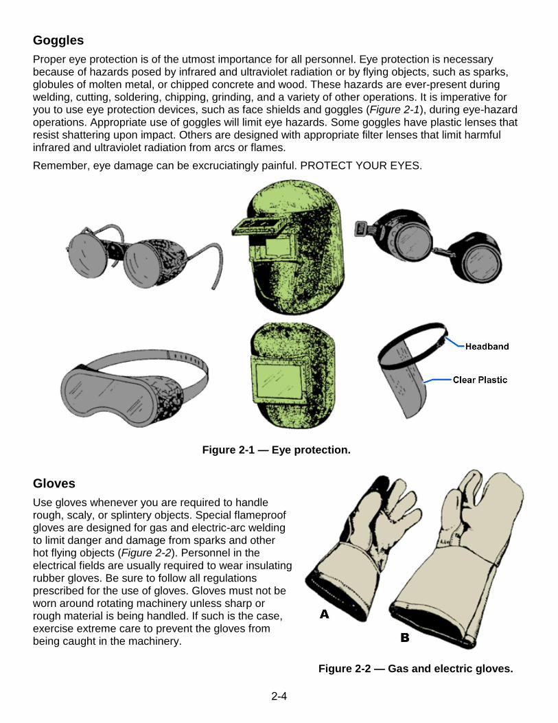
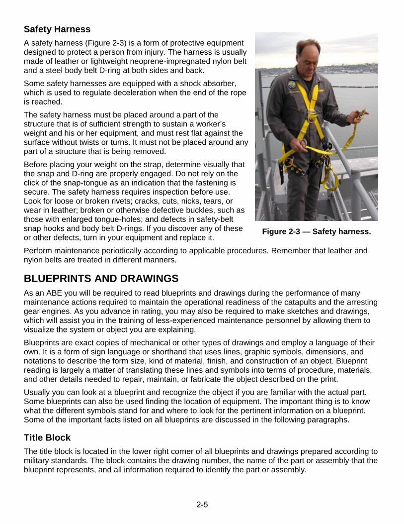
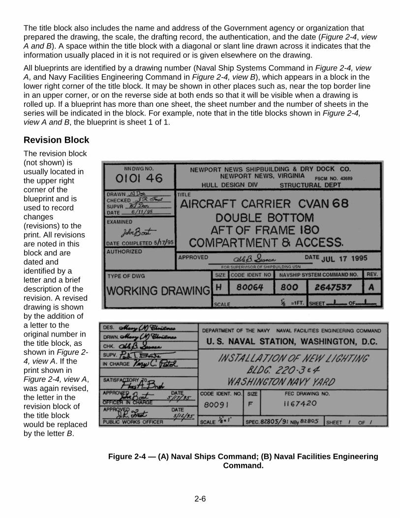
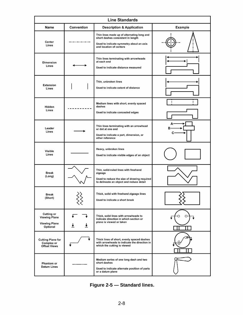
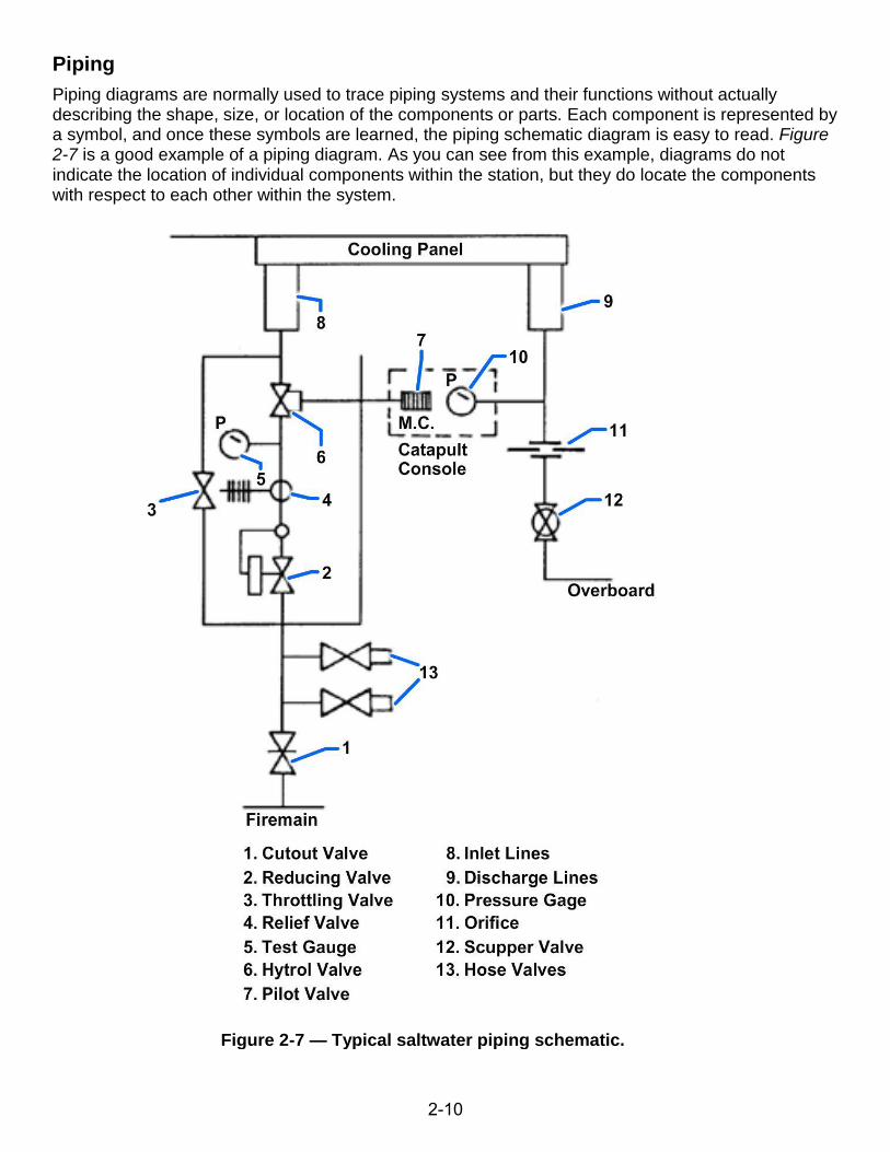
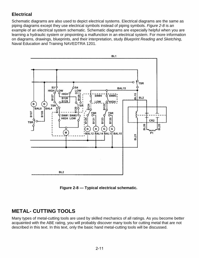
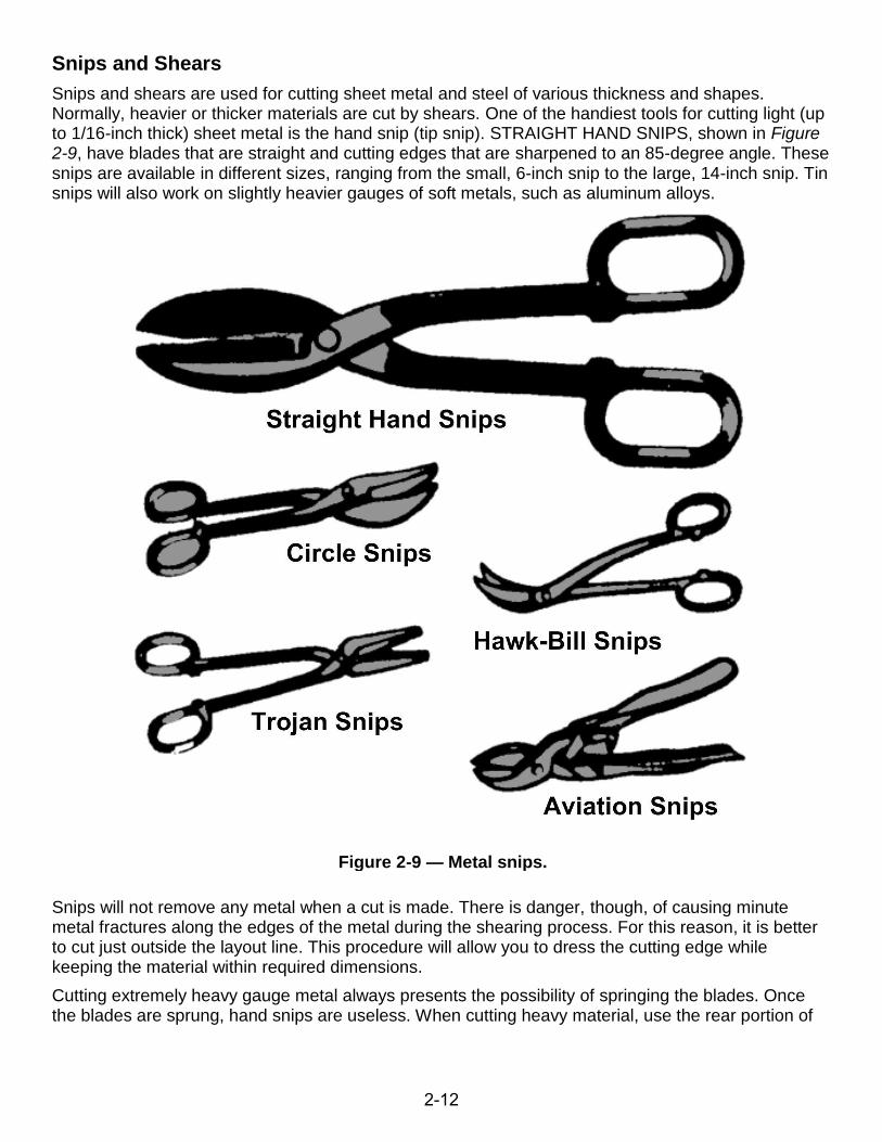
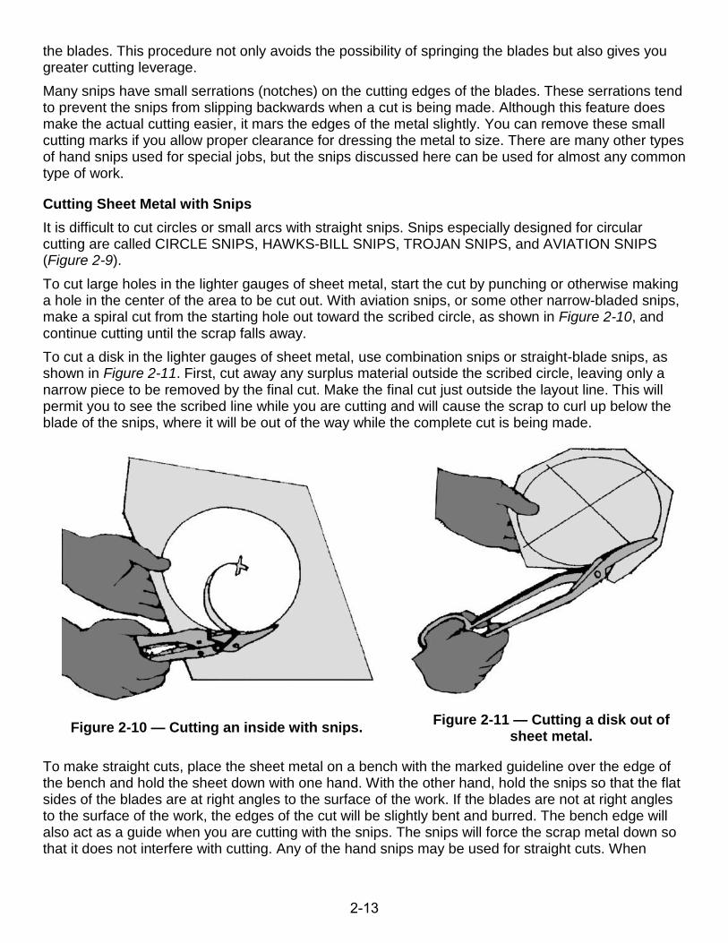
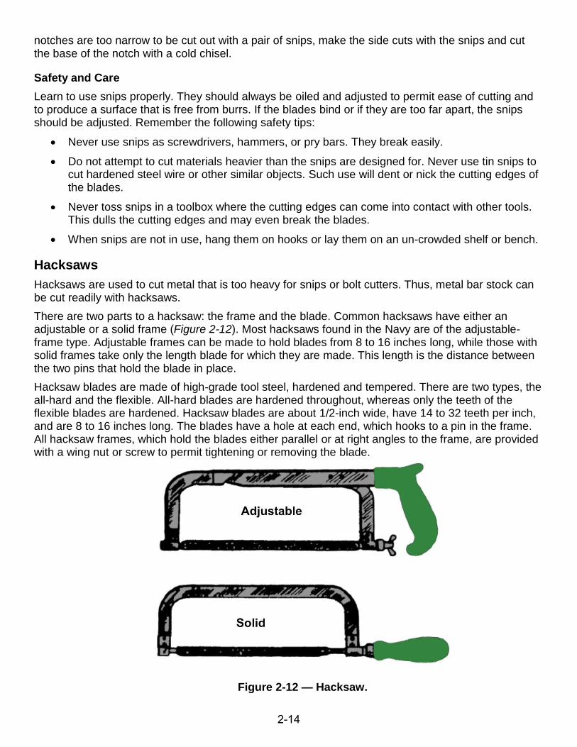
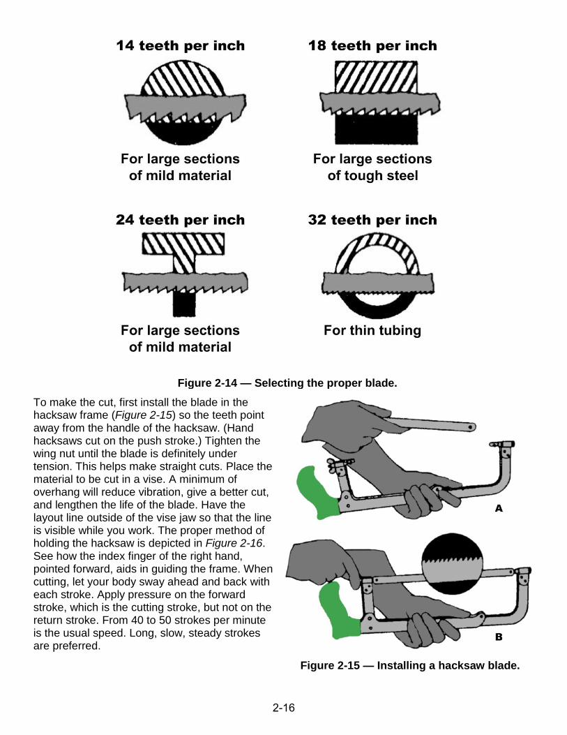
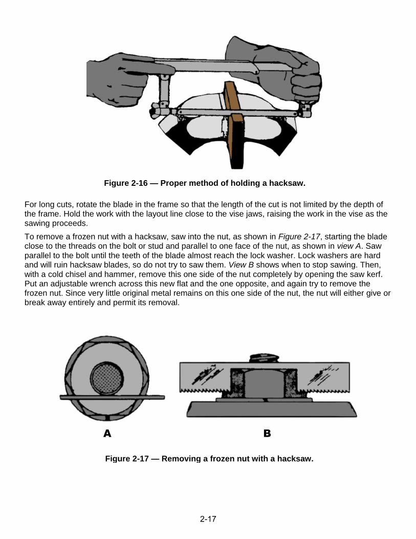
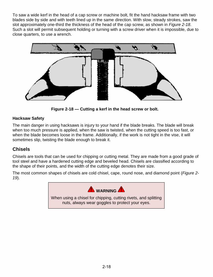
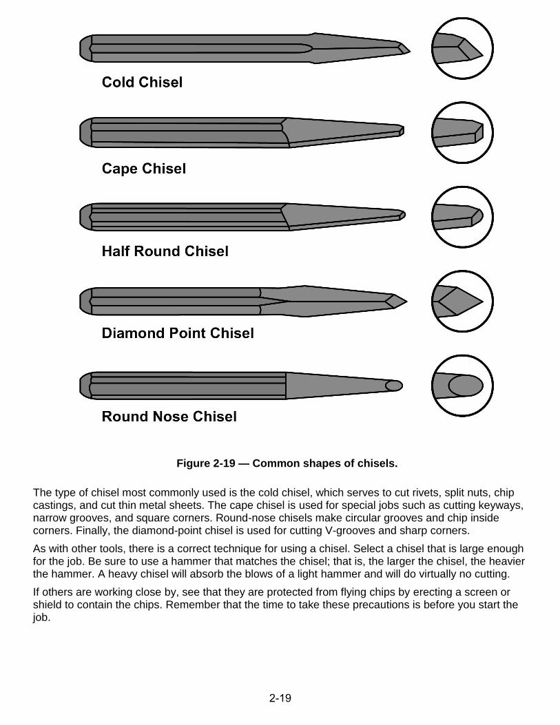
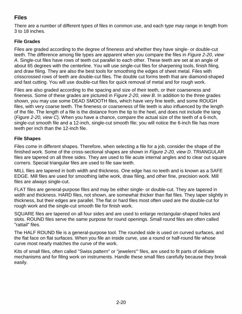
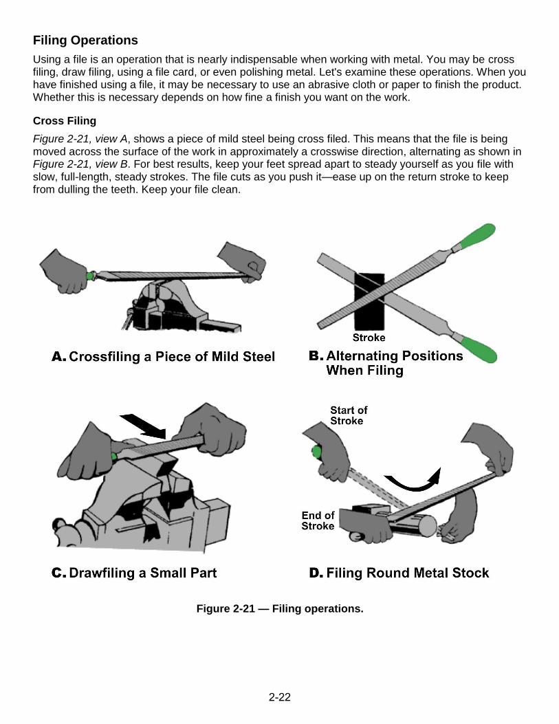
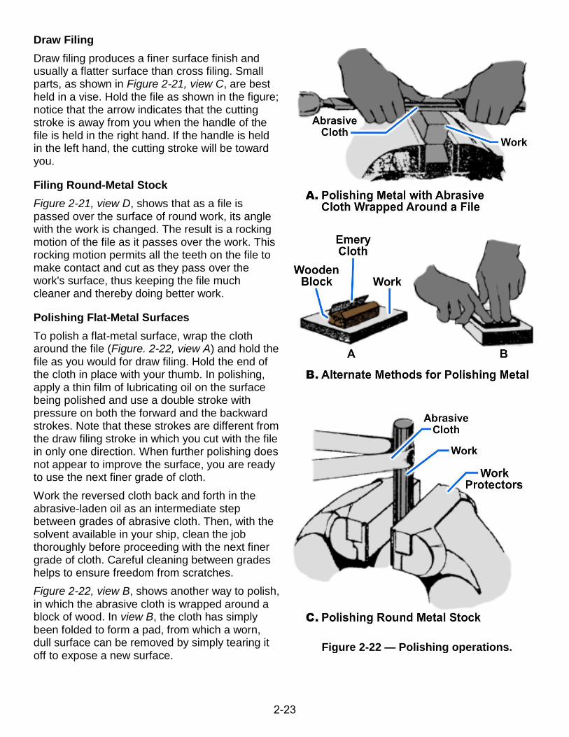
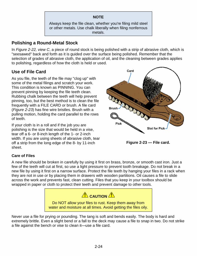
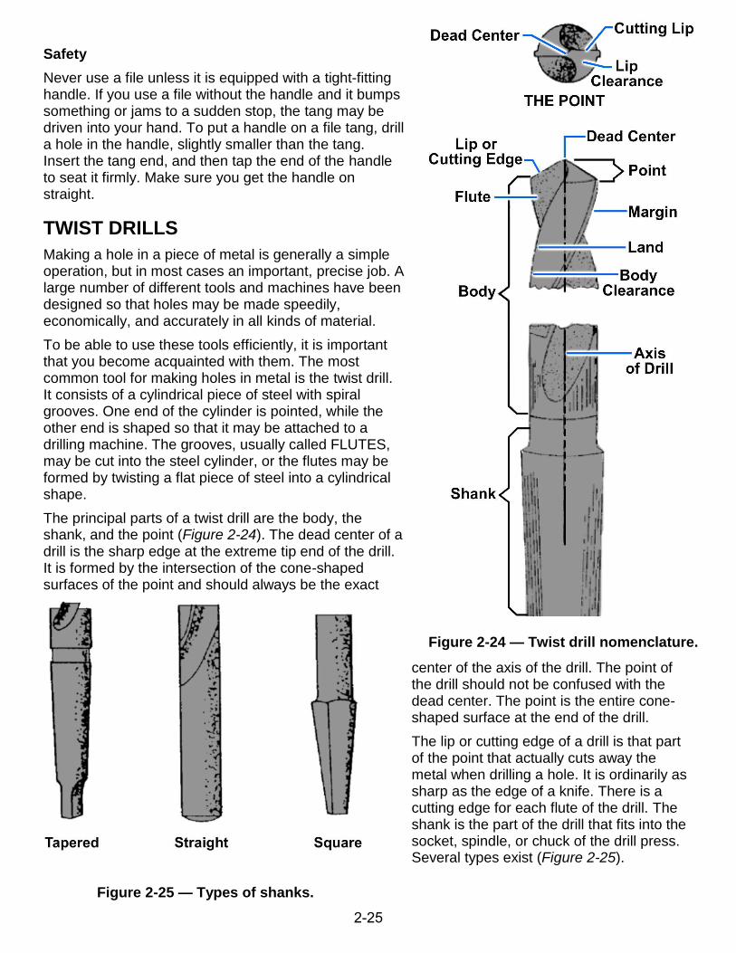
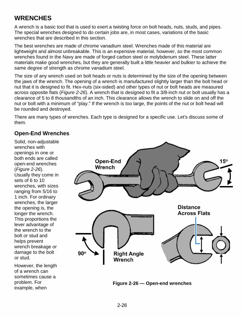
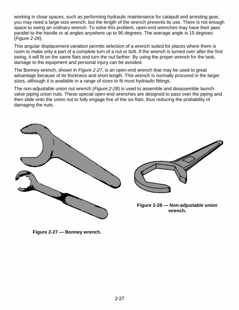
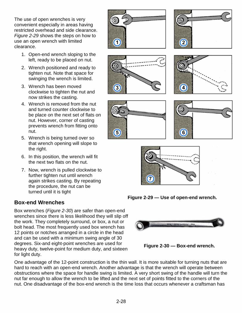
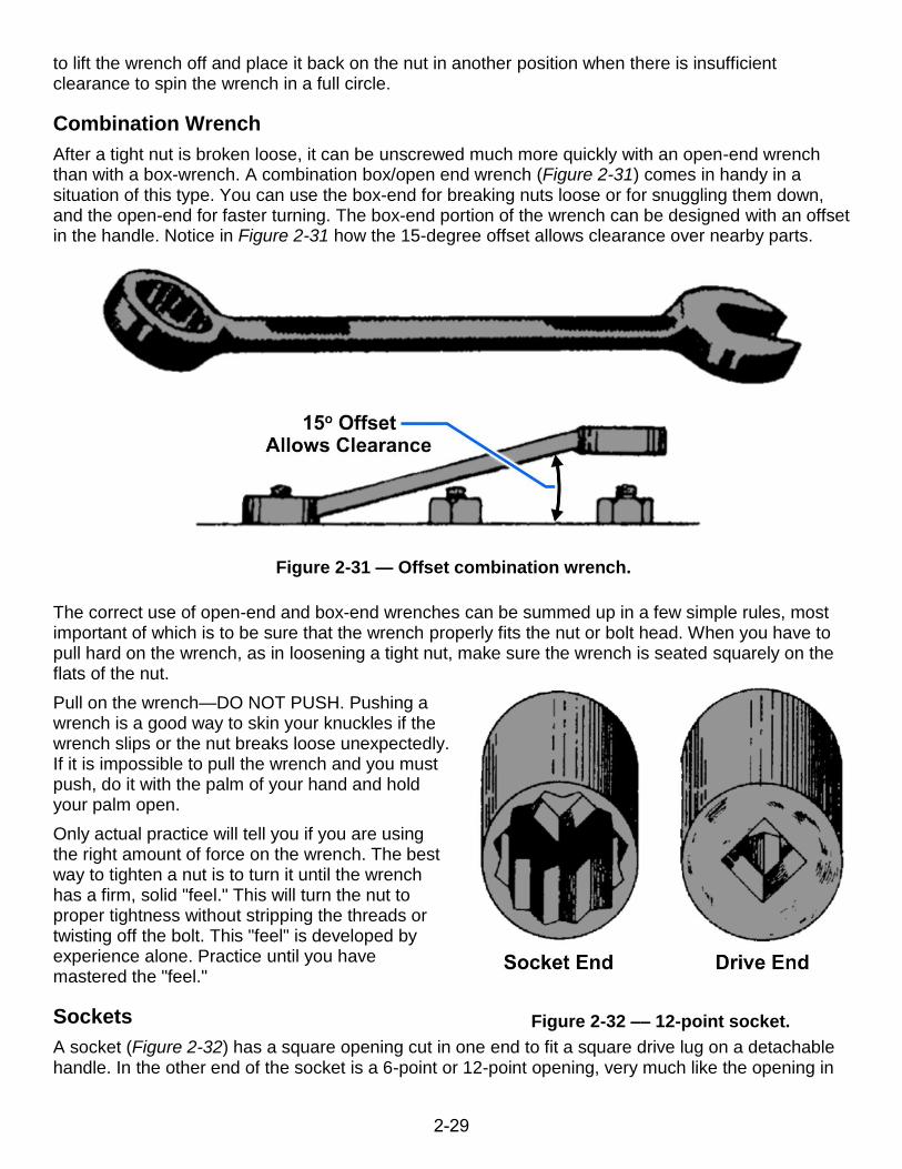
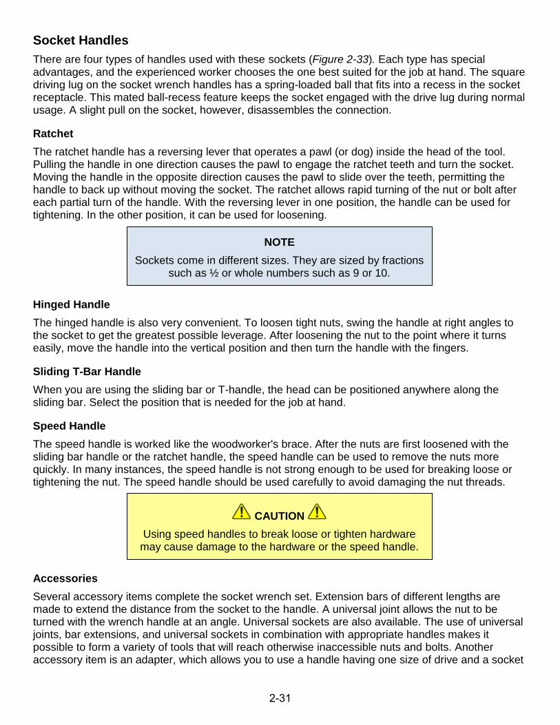
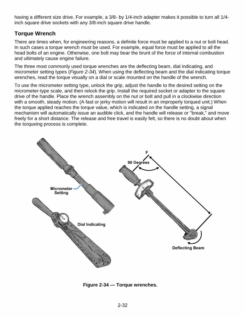
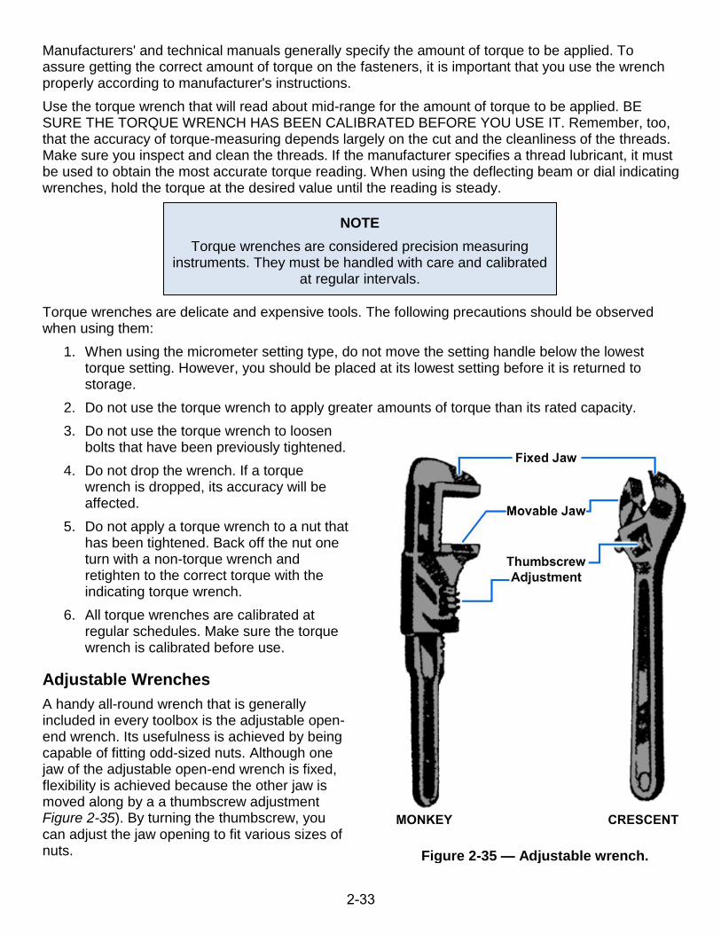
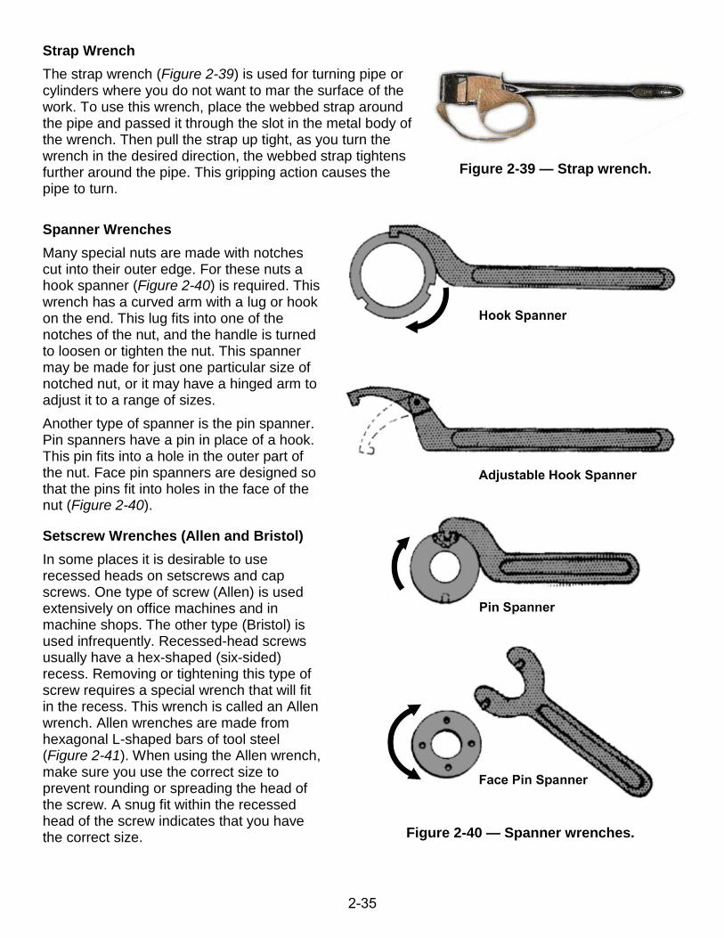
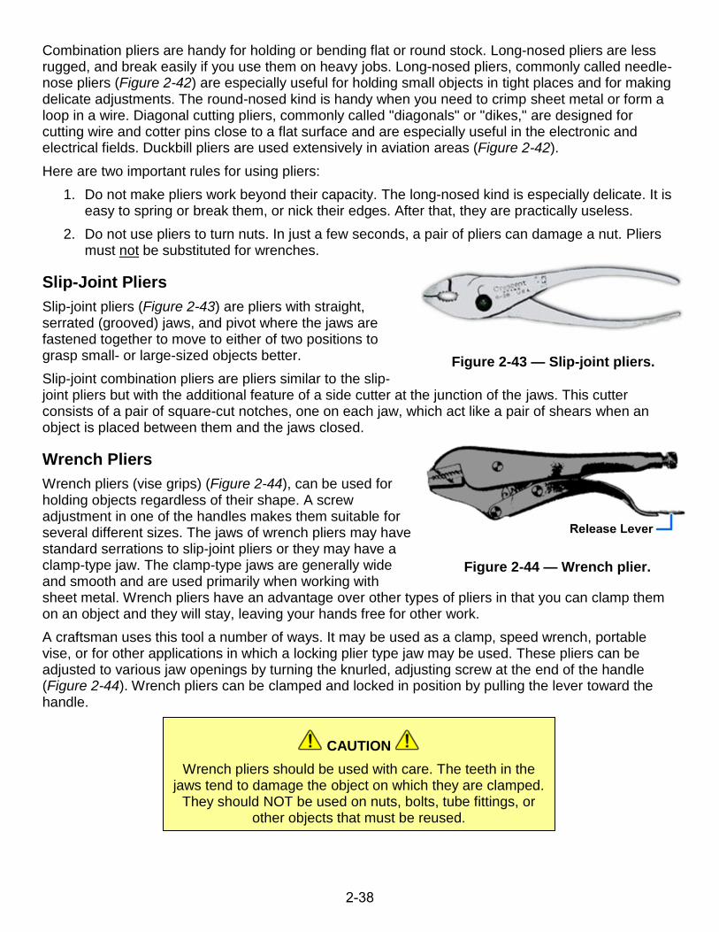
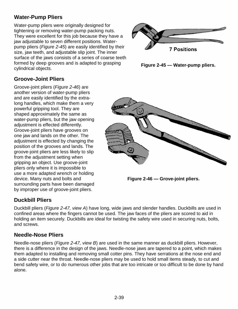
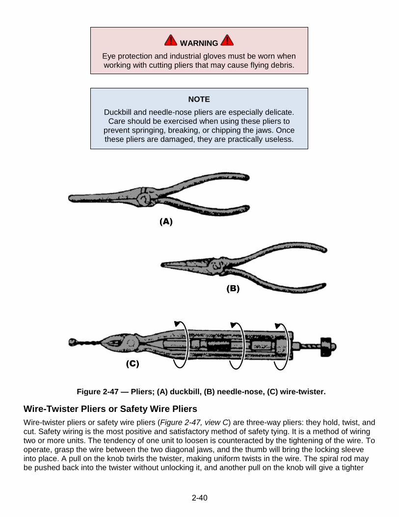
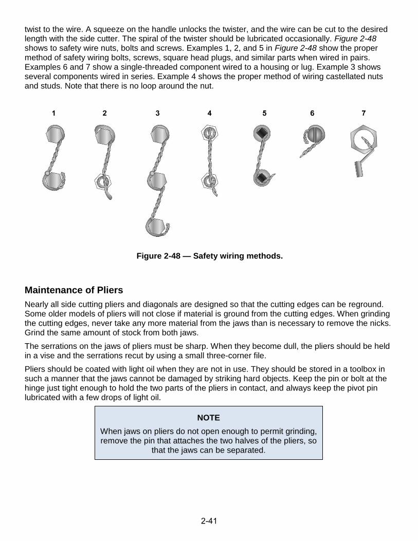
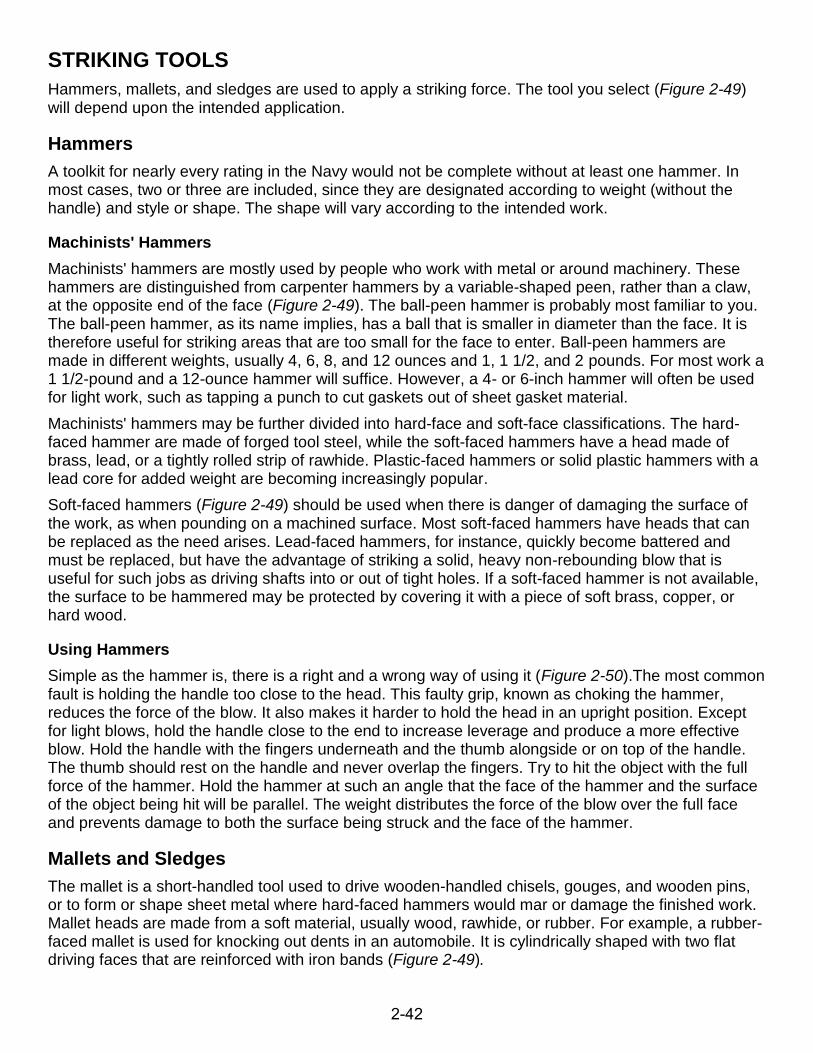
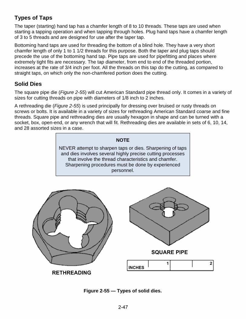
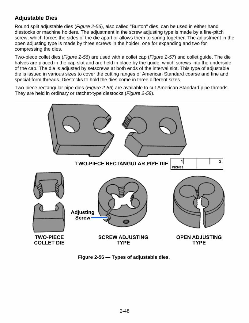
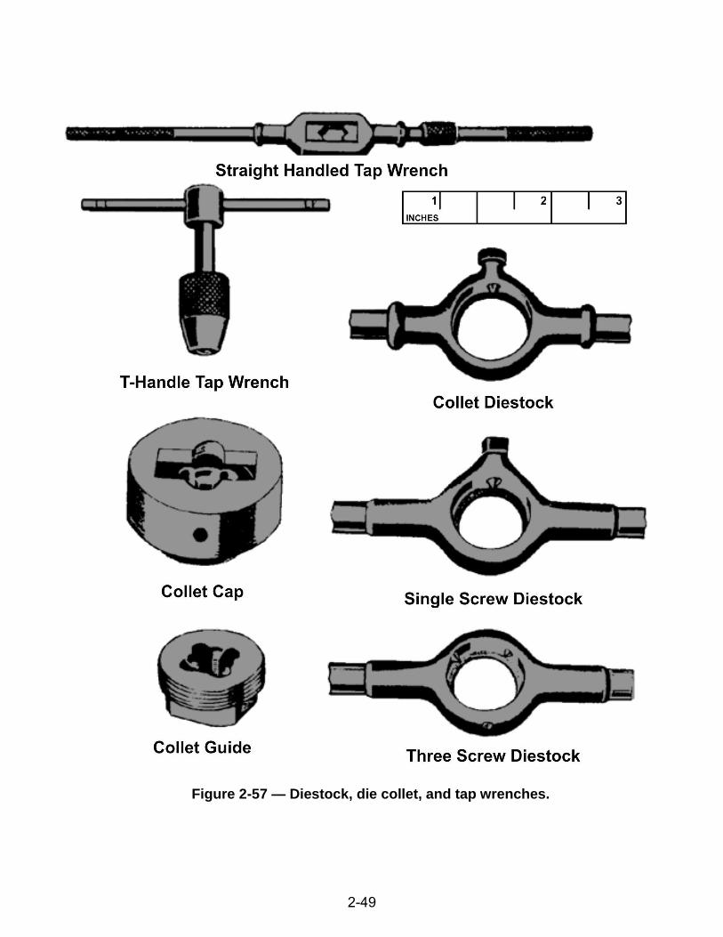
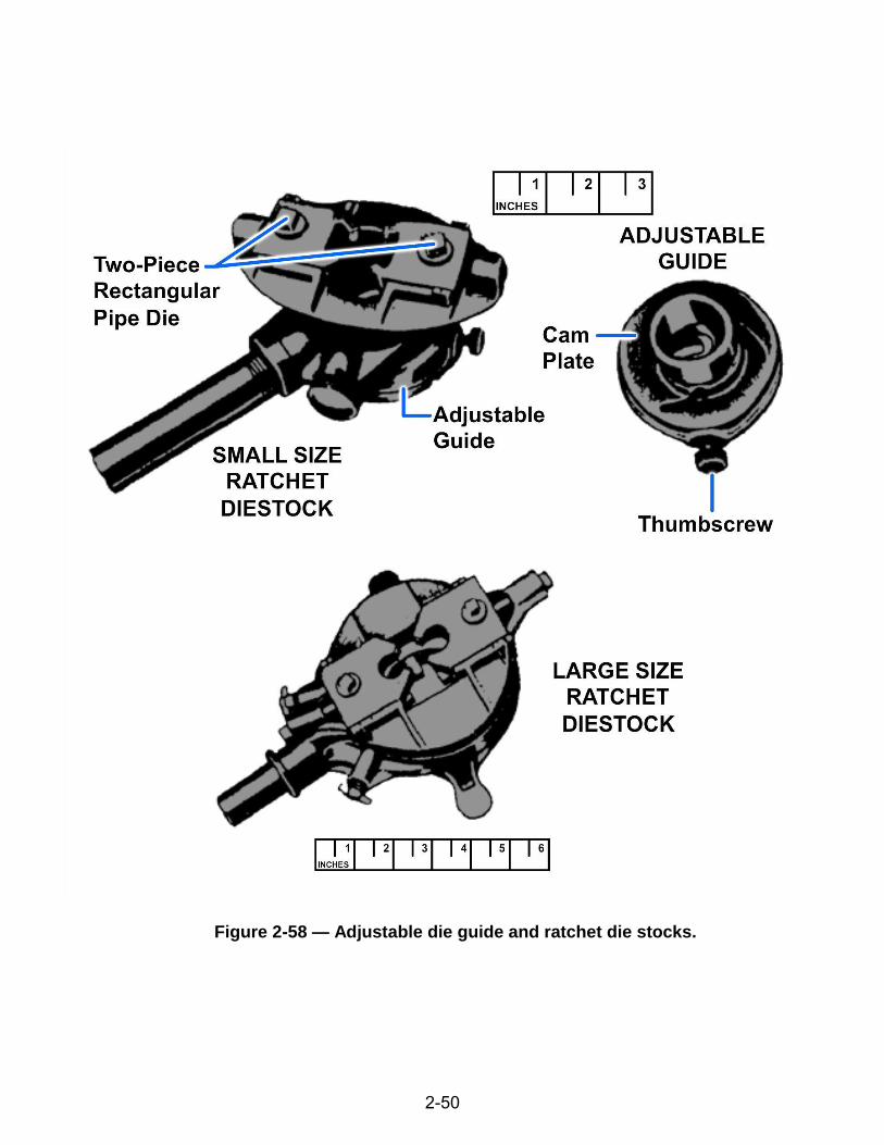
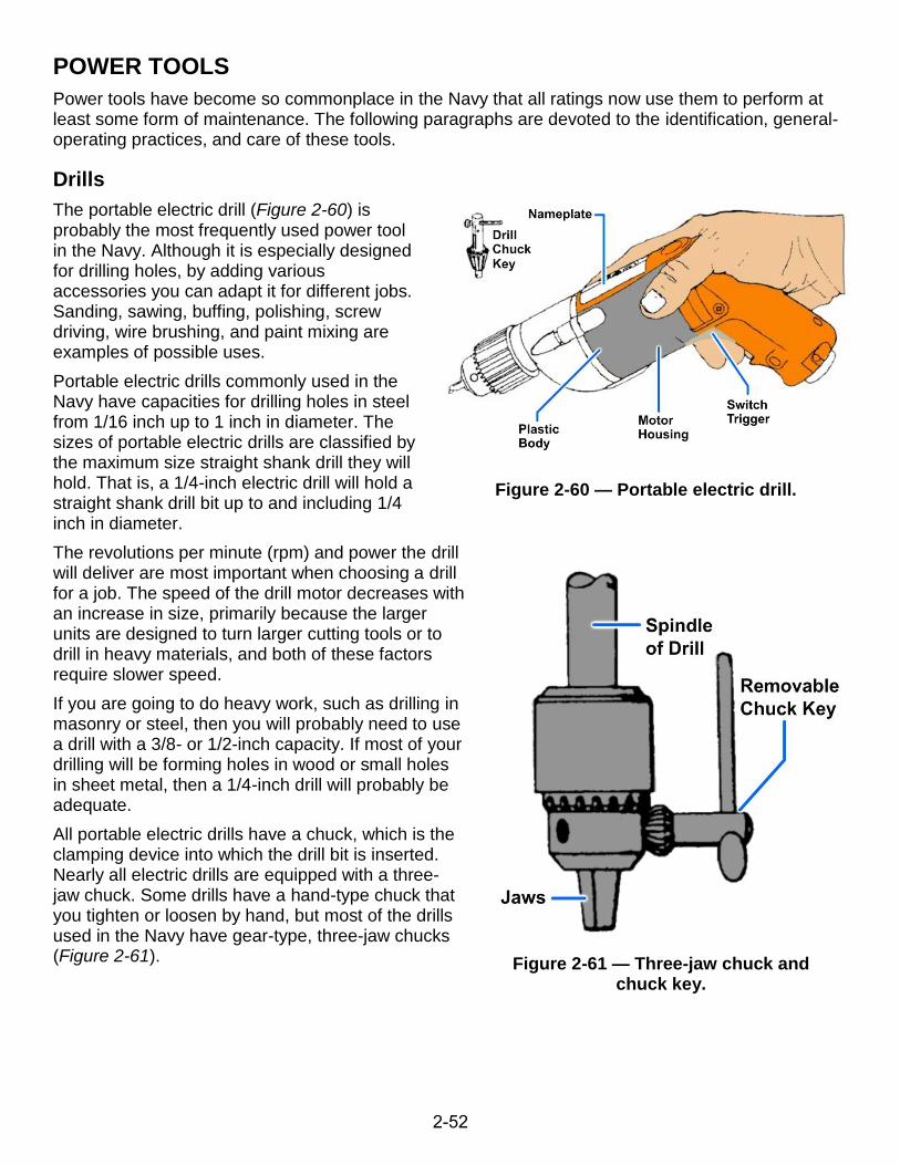
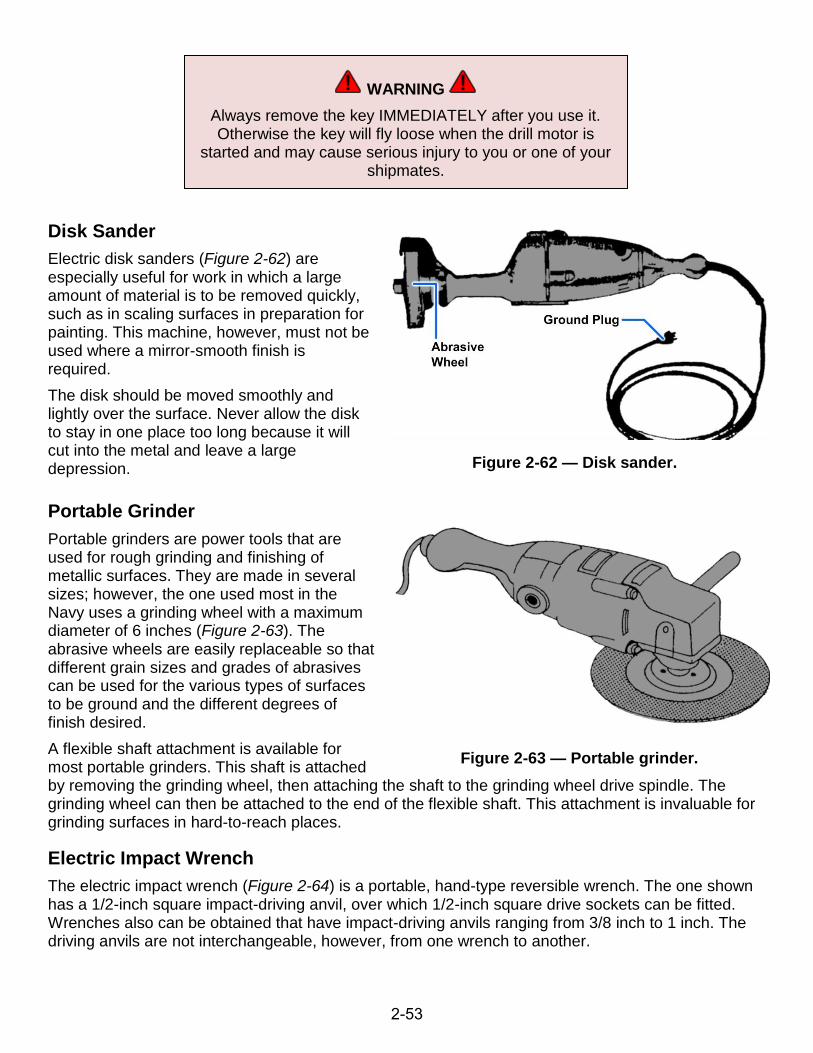
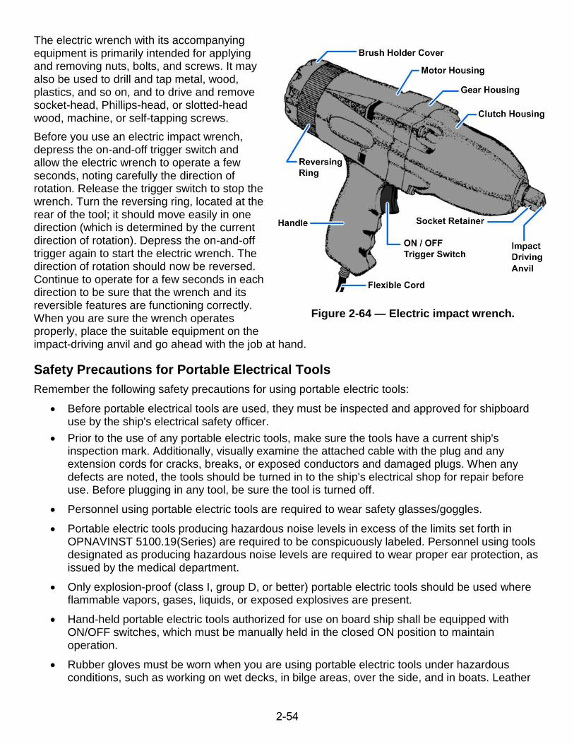
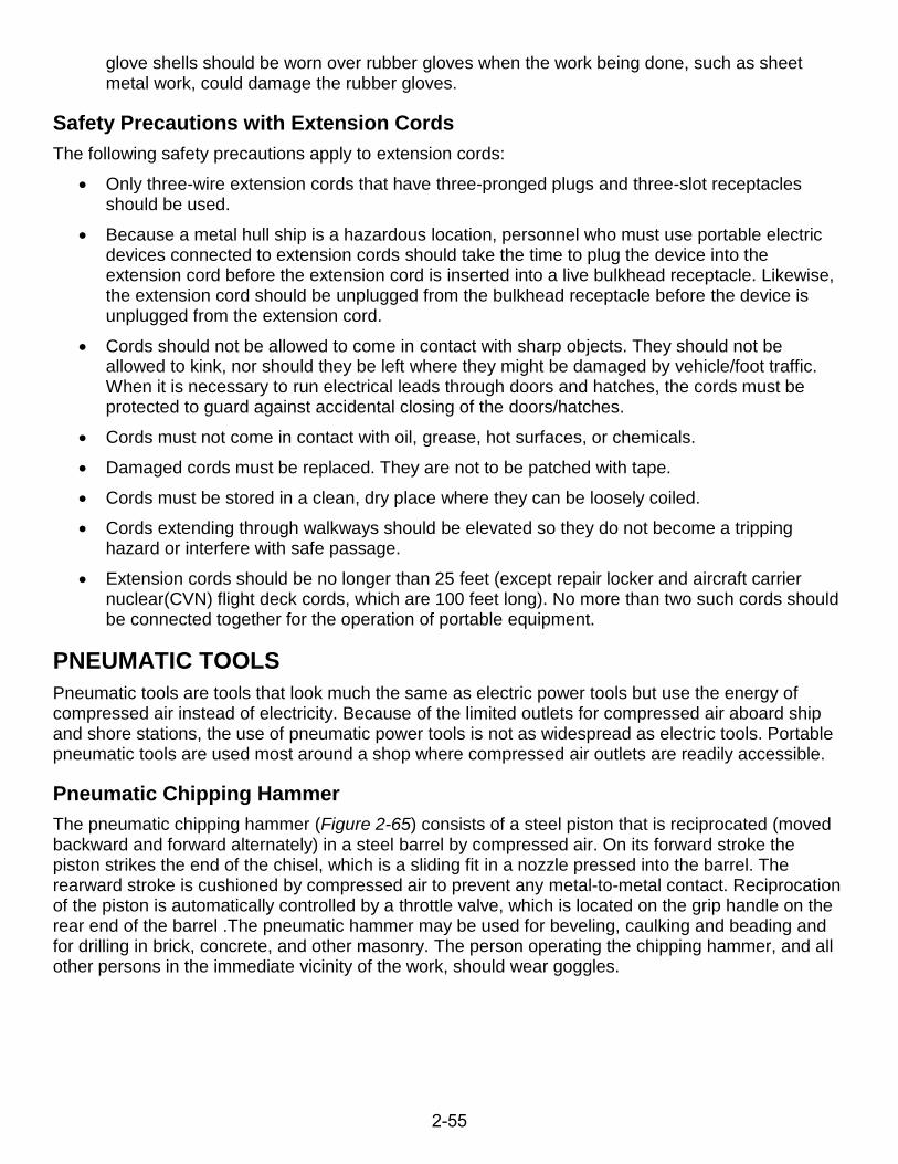
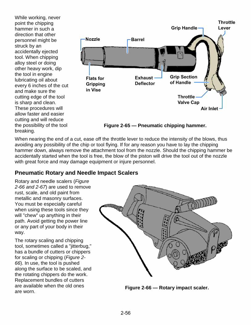
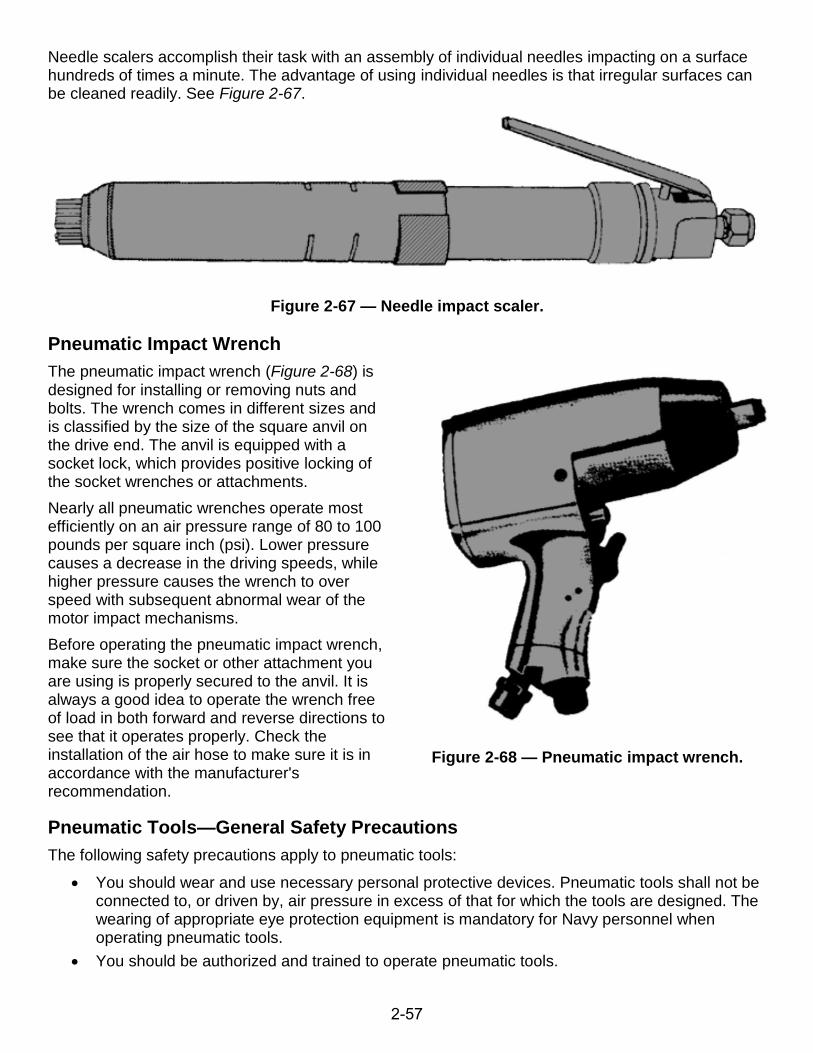
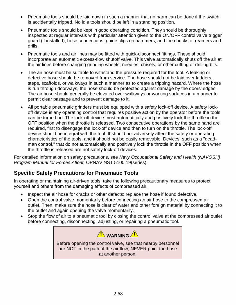
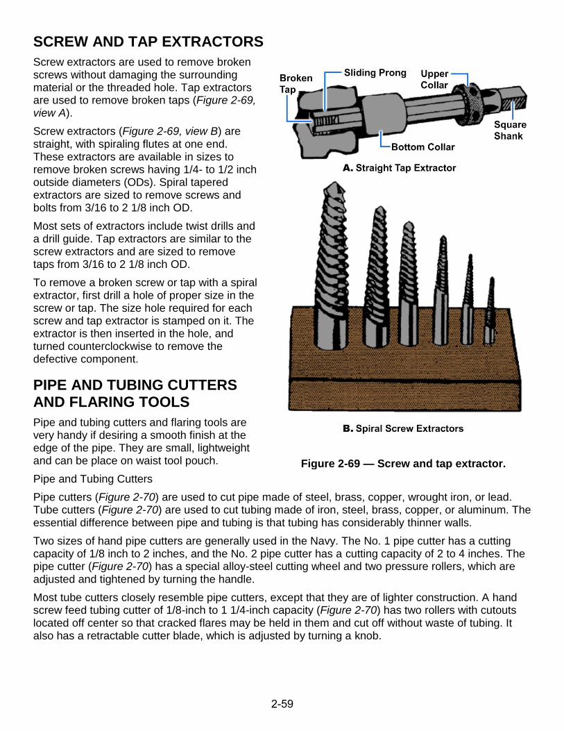
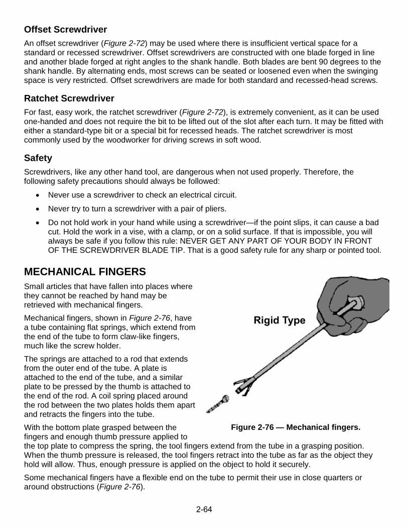
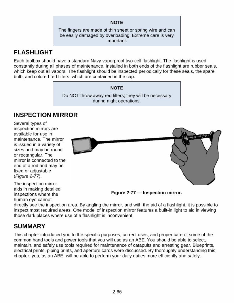