chapter 2 theoretical analysis of nonlinear...
TRANSCRIPT

23
CHAPTER 2
THEORETICAL ANALYSIS OF NONLINEAR OPTICAL
PROPERTIES OF La2CaB10O19 CRYSTAL
2.1 INTRODUCTION TO NONLINEAR OPTICS
The interaction of light with matter is usually characterized by
several phenomena, such as light absorption, refraction, scattering and
luminescence etc. All of these were regarded as properties of the material
with wavelength dependence, but independent of the light intensity. However,
the high intensity lasers can alter the optical properties of matter. Thus the
characteristic optical properties of a material become a function of intensity.
The study of such interaction of a material system in the presence of high
intense electromagnetic field is the field of nonlinear optics (NLO). Typically,
only laser light is sufficiently intense to modify the optical properties of a
material system (Robert Boyd 1992). The discovery of second-harmonic
generation (SHG) (Franken et al 1961) led to the development of many
nonlinear optical concepts.
Development in nonlinear optics took place dramatically, especially
during the last decade due to the advancement of both experimental
techniques and evolution of molecular modelling and quantum chemical
theoretical procedures. Molecules with large optical nonlinearities have
extensively been studied due to their potential applications in the area of
material science and various photonic technologies like, optical switching,
data processing and optical communication. NLO also takes a primary part in
modern technology involving lasers, sensors, interferometers, memory chips,

24
detectors, electrical devices and optical components. Frequency conversion is
one of the important and popular techniques to extend the useful wavelength
range of laboratory laser.
2.2 THEORETICAL EXPLANATION OF NONLINEAR OPTICS
When a beam of electromagnetic radiation propagates through a
solid, the nuclei and associated electrons of the atoms form electric dipoles.
The electromagnetic radiation interacts with these dipoles causing them to
oscillate, which by the classical laws of electromagnetism, results in the
dipoles themselves acting as sources of electromagnetic radiation. If the
amplitude of vibration is small, the dipoles emit radiation of the same
frequency as the incident radiation. As the intensity of the incident radiation
increases, the relationship between irradiance and amplitude of vibration
becomes nonlinear resulting in the generation of harmonics in the frequency
of radiation emitted by the oscillating dipoles. Thus frequency doubling or
second harmonic generation and indeed higher order frequency effects occur
as the incident intensity is increased.
In a nonlinear medium the induced polarization is a nonlinear
function of the applied field. A medium exhibiting SHG is a crystal composed
of molecules with asymmetric charge distributions arranged in the crystal in
such a way that a polar orientation is maintained throughout the crystal. At
very low fields, the induced polarization is directly proportional to the electric
field (Nalwa and Miyata 1996).
P = o E (2.1)
where is the linear susceptibility of the material, E is the electric field
vector, o is the permittivity of free space. At high fields, polarization

25
becomes independent of the field and the susceptibility becomes field
dependent. Therefore, this nonlinear response is expressed by writing the
induced polarization as a power series in the field.
P = o ((1)
E +(2)
E. E +(3)
E. E. E +…… ) (2.2)
where(2)
,(3)
.... are the nonlinear susceptibility of the medium.(1)
is the
linear term responsible for material’s linear optical properties like, refractive
index, dispersion, birefringence and absorption.(2)
is the quadratic term
which describes second harmonic generation in non-centrosymmetric
materials.(3)
is the cubic term responsible for third harmonic generation,
stimulated Raman scattering, phase conjugation and optical bistability. Hence
the induced polarization is capable of multiplying the fundamental frequency
to second, third and even higher harmonics. The coefficients of(1)
,(2)
and
(3) give rise to certain optical effects, which are listed in Table 2.1.
If the molecule or crystal is centro-symmetric then(2)
= 0. If a field
+E is applied to the molecule (or medium), Equation (2.2) predicts that the
polarization induced by the first nonlinear term is predicted to be +E2, yet if
the medium is centro-symmetric the polarization should be -E2. This
contradiction can only be resolved if(2)
= 0 in centro-symmetric media. If the
same argument is used for the next higher order term, + E produces
polarization +E3
and –E produces –E3, so that
(3) is the first non-zero
nonlinear term in centro-symmetric media. In second harmonic generation,
the two input wavelengths have the same frequency i.e.2 1 = 2 or ( 1 = 2 2).
During this process, a polarization wave at the second harmonic frequency
2 1 is produced. The refractive index, n1 is defined by the phase velocity and
wavelength of the medium. The energy of the polarization wave is transferred
to the electromagnetic wave at a frequency 2.

26
Table 2.1 Optical effects of nonlinear optical materials
Order Coefficient Effects Application
1. (1) Refraction Optical fibers
2. (2)SHG ( + = 2 )
Frequency mixing
( 1 2 = 3)
Pockel’s effect
( + 0 = )
Frequency doubling
Optical parametric oscillations
Electro-optical modulators
3. (3) 4 wave mixing
Gratings
Kerr effect
Optical amplitude
Raman coherent spectroscopy
Real time holography
Ultra high speed optical gates
Amplifiers, choppers etc.
The phase velocity and wavelength of this electromagnetic wave
are determined by n2, the refractive index of the doubled frequency. To obtain
high conversion efficiency, the phase vectors of input beams and generated
beams are to be matched.
k = 4(n n )
= 0
where K represents the phase-mismatch (Myoungsik 2004 ). The phase
matching can be obtained by angle tilting, temperature tuning and so on. In
general, longer crystal, large nonlinear coefficients and zero phase
mismatching will result in higher conversion efficiency. Also, the input power
density has to be lower than the damage threshold of the crystal.
2.3 NONLINEAR OPTICAL PROCESSESS AND ITS
APPLICATIONS
Nonlinear optics gives rise to a host of optical phenomena and
following are some of the important nonlinear optical processes those
exclusively involved with frequency mixing.
(2.3)

27
A. Second harmonic generation (SHG)
B. Third harmonic generation (THG)
C. High harmonic generation (HHG)
D. Sum frequency generation (SFG)
E. Difference frequency generation (DFG)
F. Optical parametric amplification (OPA)
G. Optical parametric oscillation (OPO)
H. Optical parametric generation (OPG)
I. Spontaneous parametric down conversion (SPDC)
J. Optical rectification (OR)
Not all wavelength regions of interest are directly accessible
with lasers. Therefore, it is common e.g. to generate visible light by nonlinear
conversion of infrared light from one or several lasers.
2.4 BIREFERENGENT CRYSTALS
Birefringence, or double refraction, is the decomposition of
a ray of light (or electromagnetic radiation) into two rays (the ordinary
ray and the extraordinary ray) when it passes through certain types of
material, such as calcite crystals or boron nitride, depending on
the polarization of the light. This effect can occur only if the structure of the
material is anisotropic (directionally dependent). If the material has a single
axis of anisotropy or optical axis (i.e. it is uniaxial) birefringence can be
formalized by assigning two different refractive indices to the material for
different polarizations. The birefringence magnitude is then defined by,
(2.4)

28
where ne and no are the refractive indices for polarizations parallel
(extraordinary) and perpendicular (ordinary) to the axis of anisotropy
respectively. The reason for birefringence is the fact that in anisotropic media
the electric field vector and the dielectric displacement can be nonparallel
(namely for the extraordinary polarisation), although being linearly related.
Generally there are two types of birefringent crystals and they are: 1. uniaxial
crystals and 2. biaxial crystals.
2.4.1 Uniaxial Crystals
In uniaxial crystals a special direction exists called the optic axis
(Z axis). The plane containing the Z axis and the wave vector k of the light
wave is termed the principal plane. The light beam whose polarization (i.e.,
the direction of the vector E oscillations) is normal to the principal plane is
called an ordinary beam or an o-beam. The beam polarized in the principal
plane is known as an extraordinary beam or e-beam. The refractive index of
the o-beam does not depend on the propagation direction, whereas for the e-
beam it does. Thus, the refractive index in anisotropic crystals generally
depends both on light polarization and propagating direction.
The value of n is equal to zero along the optic axis Z and reaches
a maximum in the direction normal to this axis. The refractive indices of the
ordinary and extraordinary beams in the plane normal to the Z axis are termed
the principal values of the refractive index and are denoted by no and ne,
respectively.
The dependence of the refractive index on light propagation
direction inside the uniaxial crystal (index surface) is a combination of a
sphere with radius no (for an ordinary beam) and an ellipsoid of rotation with
semiaxes no and ne (for an extraordinary beam, the axis of the ellipsoid of

29
rotation is the Z axis). In the Z axis direction the sphere and ellipsoid are in
contact with each other. In a negative crystal the ellipsoid is inscribed in the
sphere (Figure 2.1(a)), whereas in a positive crystal the sphere is inscribed in
the ellipsoid (Figure 2.1(b)).
Uniaxial birefringent materials are classified as positively (or
negatively) birefringent when, for light directed perpendicularly to the optic
axis, the refractive index of light polarized parallel to the optic axis is greater
(or smaller, respectively,) than light polarized perpendicularly to the optic
axis [Brad Amos 2005]. In other words, the polarization of the slow (or fast)
wave is parallel to the optical axis when the birefringence of the crystal is
positive (or negative, respectively).
Negative uniaxial crystals (eg. Calcite CaCO3, Ruby Al2O3) have
ne < no so for these crystals, the extraordinary axis (optic axis) is the fast axis
whereas for positive uniaxial crystals (eg. Quartz SiO2, Magnesium fluoride
MgF2, utile TiO2), ne > n o and thus the extraordinary axis (optic axis) is the
slow axis.
Figure 2.1 Dependence of refractive index on light propagation direction
and Polarization in negative (a) and positive (b) uniaxial
crystals
(a(b

30
2.4.2 Biaxial Crystals
In biaxial crystals, the dependence of the refractive index on light
propagation direction and it's polarization (index surface) corresponds to a
much more complex function than for the uniaxial crystals. The resulting
surface has a bilayer structure with four points of interlayer contact through
which two optic axes pass. Similar to the case of a uniaxial crystal, the
propagation direction of plane light wave is defined by two angles: polar
and azimuthal .
For simplicity we confine ourselves to the case of light propagation
in the principal planes XY, YZ and XZ. In these planes the dependences of
the refractive index on the propagation direction of two waves with
orthogonal polarizations represent a combination of an ellipse and a circle
(Fig. 2.2 a, b). We shall relate dielectric (X, Y, Z) and crystallographic (a,b,c)
axes in a biaxial crystal in such a way that the optic axes, whose directions are
given by the intersection points of the ellipse and circle, will always lie in the
principal plane XZ.
Figure 2.2 Dependence of refractive index on light propagation direction
and polarisation in biaxial crystals in relations between
principal values of refractive indices are, a) n <n < nz and b)
n > ny > nz.
(a) (b)

31
Considering one of two possible cases: n <n < nz (Figure 2.2 (a)),
where n , ny, and nz are the principal values of the refractive indices. The
angle Vz formed by one of the optic axes with the axis Z can be found
(Dimitriev 1991) from the expression
sin V =–
(2.5)
The angle between optical axes in the plane XZ is equal to 2Vz. In
the plane XY the refractive index of the wave polarized normally to this plane
is constant and equals nz, and that of the wave polarized in this plane changes
from n to n with varying from 0° to 90°. Hence, a biaxial crystal with n
<n < nz in the plane XY is similar to a negative uniaxial crystal with no = nz
and
n ( ) = n)
[ ] (2.6)
In the plane YZ the refractive index of the wave polarized normally
to this plane is constant and equals n , whereas for the wave polarized in this
plane the refractive index changes from n to nz with varying from 0° to 90°.
Hence, a biaxial crystal with n <n < nz in the plane YZ is similar to a
positive uniaxial crystal with no = n and
n ( ) = n)
[ ] (2.7)
We can also see that in the plane XZ at < Vz a biaxial crystal with
n < n < nz is similar to a negative uniaxial crystal and, at > Vz, to a positive
uniaxial crystal. A biaxial crystal with n > n > nz can be considered in a

32
similar way (Figure 2.2(b)). Here the angle Vz between the optic axis and the
axis Z is expressed as,
cosV =n (n – n )
n (n n )(2.8)
The biaxial crystal is said to be optically positive if the bisectrix of
the acute angle between optic axes coincides with nmax, and optically negative
if the bisectrix coincides with nmin.
2.5 NONLINEAR OPTICAL BORATE CRYSTALS
The continuing demand for new laser systems with unique
wavelength and high power, the search for new specific frequency converting
materials continues. In terms of materials that are reasonably well developed
today, the materials for NLO applications in the IR (2-20 µm) are
chalcopyrites (e.g., AgGaSe2, ZnGeP2), for the visible and near UV materials
such as KNbO3, KTiOPO4 are used. For VUV (vacuum ultraviolet) and
visible regions mainly borates such as BBO and LBO are suitable. The borate
crystals BBO and LBO are two such materials have gained widespread use
during the past few years. Their uitility derives from exceptional optical
damage thresholds, wide transparency ranges, mechanical durability, and
favourable linear and non-linear optical properties. The collective existence of
these properties in individual compounds has resulted in several unique
performance characteristics that include generation of coherent light to
wavelengths >200 nm and the production of continuously tunable, high power
coherent radiation of wavelength 350-2400nm. Since, both BBO and LBO are
commercially success for device applications, many efforts toward the
development of new inorganic NLO borates are concentrated by materials
scientists and researchers having complementary properties to those of LBO
and BBO or improved properties. Some of the main aims of the development

33
of new borates have been the production of materials with relatively large
SHG coefficients, moderate birefringence, short UV cutoff and congruent
melting.
Borate NLO crystals for high-power UV light generation and for
other NLO processes were developed. CBO, CLBO, GdYCOB, KAB, YCOB,
SBBO, KBBF are some of those important crystals which are being used for
present technological applications. There are number of borates, the most
important ones being lithium triborate (LiB3O5 = LBO), cesium lithium borate
(CLBO, CsLiB6O10), -barium borate ( -BaB2O4 = BBO, often used in
Pockels cells), bismuth triborate (BiB3O6 = BIBO), and cesium borate
(CSB3O5 = CBO). Yttrium calcium oxyborate (YCOB) is also available in
rare-earth-doped form and can be used as a laser gain medium. Further it is
simultaneously used for generation and frequency-conversion of laser light.
Less frequently used are strontium beryllium borate (Sr2Be2B2O7 = SBBO)
and K2Al2B2O7 (KAB). LBO, BBO, CLBO, CBO and other borate crystals
are suitable for the generation of relatively short wavelengths, e.g. in green
and blue laser sources, and for UV generation, because their bandgap energy
is relatively high, the crystals are relatively resistant to UV light, and there are
suitable phase-matching options. Borates such as LBO and BBO also work
well in broadly tunable optical parametric oscillators and optical parametric
chirped-pulse amplification.
Lanthanum Calcium Borate (LCB) is a biaxial borate crystal. The
birefringence ( ) of the crystal is 0.053 at 1064 nm (Yicheng Wu et al
2003). Using the LCB single crystals, the phase matching is possible down to
315nm (SHG). The effective nonlinear co-efficient of LCB in XZ plane is
about 1.05 pm/V and is 2.7 times greater as that of KDP (KH2PO4 which is
0.384 pm/V). The LCB crystal shows two photon absorption (TPA) induced
by a UV laser field and its efficiency is nearly three times that in the case of
BiBO crystals. Also it is reported that the crystals can be used as optically

34
operated limiters over a wide spectral range (Kityk et al 2006). Further it is
reported that, based on the band energy dispersion and density of states
calculation shows that LCB is a semiconductor with a small indirect energy
gap of 1.5eV (Reshak et al 2006). Table 2.2 shows the characteristics of LCB
crystal which is compared with other well known borate materials.
Table 2.2 Characteristics of LCB compared with other borate crystal
materials
Crystal
UV
absorption
edge nm
Shortest SHG
wavelength
nm
n
@
1064nm
deff
(pm/V)Hygrocopicity
LCB 280 288 0.053 1.05 Non-Hygroscopic
BBO 189 205 0.112 2.01 Hygroscopic
BiBO 270 286 0.031 3.3 Non-Hygroscopic
YCOB 220 360 0.041 1.1 Non-Hygroscopic
GdCOB 320 420 0.033 1.3 Non-Hygroscopic
2.6 SELLMEIER EQUATION
Sellmeier equation gives the relation between refractive index and
wavelength for a particular transparent medium. The equation is used to
determine the dispersion of light in the medium. The sellmeier plot gives us
the information about the change in the value of the refractive index nx, ny and
nz of the material in the three different directions along X, Y, Z for a range of
wavelength. A Sellmeier equation is a basic tool for calculating phase-
matching configurations for nonlinear frequency conversion.
The general form of the sellmeier equation is written as,
n = A +B
C D (2.9)
35
where, is wavelength expressed in µm and A, B, C, D are constant
parameters and is called sellmeier co-efficients.
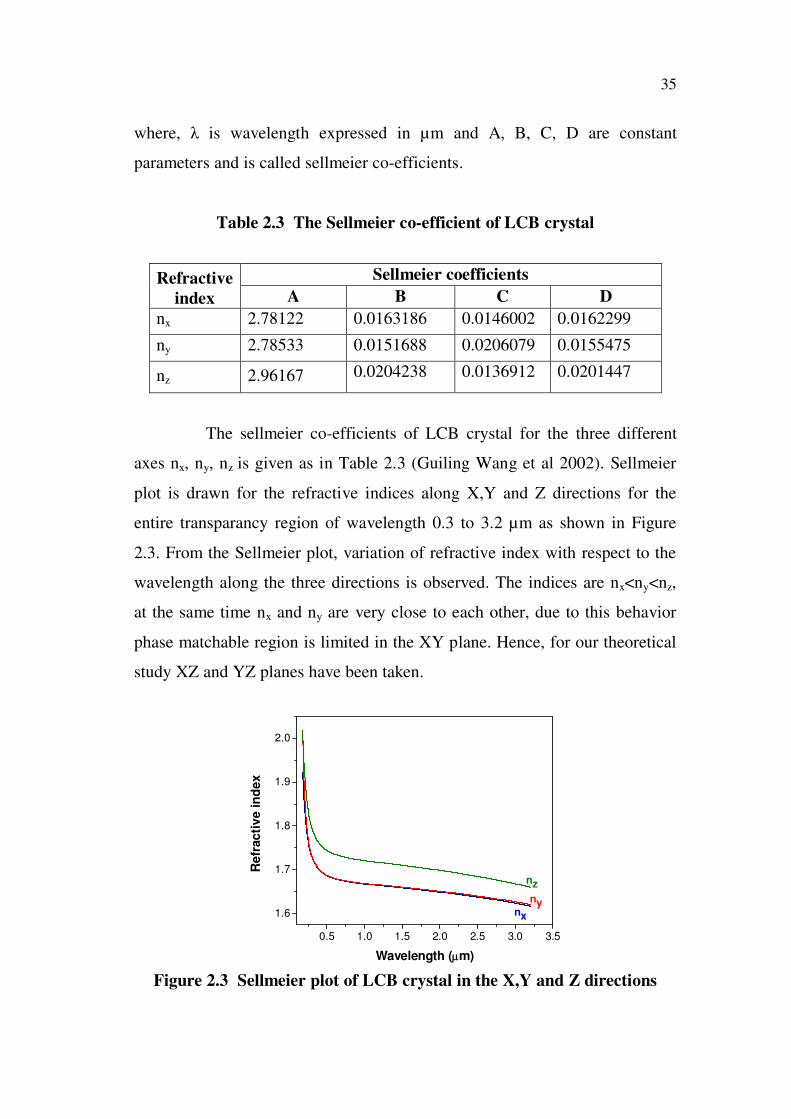
Table 2.3 The Sellmeier co-efficient of LCB crystal
Refractive
index
Sellmeier coefficients
A B C D
nx 2.78122 0.0163186 0.0146002 0.0162299
ny 2.78533 0.0151688 0.0206079 0.0155475
nz 2.96167 0.0204238 0.0136912 0.0201447
The sellmeier co-efficients of LCB crystal for the three different
axes nx, ny, nz is given as in Table 2.3 (Guiling Wang et al 2002). Sellmeier
plot is drawn for the refractive indices along X,Y and Z directions for the
entire transparancy region of wavelength 0.3 to 3.2 µm as shown in Figure
2.3. From the Sellmeier plot, variation of refractive index with respect to the
wavelength along the three directions is observed. The indices are nx<ny<nz,
at the same time nx and ny are very close to each other, due to this behavior
phase matchable region is limited in the XY plane. Hence, for our theoretical
study XZ and YZ planes have been taken.
Figure 2.3 Sellmeier plot of LCB crystal in the X,Y and Z directions
0.5 1.0 1.5 2.0 2.5 3.0 3.5
1.6
1.7
1.8
1.9
2.0
Refr
acti
ve i
nd
ex
Wavelength ( m)
nx
ny
nz

36
2.7 PHASE MATCHING
Phase matching is a technique for achieving efficient nonlinear
interactions in a medium. Many phase-sensitive nonlinear processes require
phase matching to be efficient. Essentially, this means ensuring that a proper
phase relationship between the interacting waves (for optimum nonlinear
frequency conversion) is maintained along the propagation direction, so that
the amplitude contributions from different locations to the product wave are
all in phase. This leads to the condition that some phase mismatch has to be
close to zero. For example, for type I phase matching of frequency doubling
with collinear beams the phase mismatch is given by,
k = k 2k (2.10)
where k1 and k2 are the wavevectors of the fundamental and second-harmonic
beam respectively. Without chromatic dispersion, k2 = 2 k1 would hold, so that
the phase mismatch vanishes. However, dispersion generally causes a non-
zero phase mismatch (Figure 2.4) if no special measures (as discussed below)
are taken to avoid this. Due to chromatic dispersion, the wavenumber of the
second harmonic is more than twice as large as that for the fundamental wave.
This can be avoided, e.g., by choosing a different polarization in a
birefringent crystal.
Figure 2.4 Phase mismatch for second-harmonic generation. Addition
of amplitude contributions from different parts of the crystal

37
Figure 2.4 illustrates how a phase mismatch keeps the efficiency
low. Here, the arrows illustrate the phasors corresponding to the complex
amplitude contributions from different parts of the nonlinear crystal to the
harmonic wave. Only when phase matching is achieved, these contributions
add up constructively, and a high power conversion efficiency is achieved.
Otherwise, the direction of energy transfer changes periodically (possibly
thousands of times during the passage through the crystal) according to the
change in the phase relation between the interacting waves. The energy then
oscillates between the waves rather than being transferred in a constant
direction. The effect on the power conversion is illustrated in Figure 2.5.
Solid curve shows a phase matched case, with the power growing in
proportion to the square of the propagation distance. Dashed curve represents
non phase-matched case, with the second harmonic power oscillating between
zero and a small value.
Figure 2.5 Growth of second harmonic power in a crystal along the
propagation direction, assuming constant pump intensity
For devices such as frequency doublers or optical parametric
amplifiers, phase matching needs to be actively arranged. On the other hand,

38
an optical parametric oscillator may automatically choose its signal
wavelength so that phase matching is achieved. Wavelength tuning can thus
be achieved by influencing the phase-matching conditions e.g. via
temperature changes or angular adjustments. In many cases, the nonlinear
mixing products can be efficiently accumulated over a greater length of
crystal only if phase matching is achieved. Otherwise, the field amplitudes at
the exit face, generated at different locations in the crystal, essentially cancel
each other, and the apparent nonlinearity is weak.
2.7.1 Phase Matching in Birefringent Crystal
In anisotropic media the ordinary and extraordinary waves can be
mixed and phase matching can be obtained because it is possible to tune the
index of refraction of the transmitted extraordinary wave by varying the angle
between the k-vector and the optical axis of the medium, i.e. the wavelength
dependence of the index of refraction. As a result the indices no and ne and
therewith ne ( ) are a function of the incoming light.
0.5 1.0 1.5 2.0
1.68
1.71
1.74
1.77
1.80XZ plane
Re
frac
tive
in
dex
Wavelength ( m)
0.532 m
ne( )
no = nz
1.064 m
Figure 2.6 Sellmeier plot of the XZ plane aiming for phase matching at
1.064 µm

39
The two curves for no and ne ) in Figure 2.6 represent the
maximum and the minimum attainable index of refraction in the XZ plane,
and the whole range in between the two curves covers the possible indices of
refraction. In particular, the curves no and ne ) in Figure 2.6 are drawn to
show the phase matching at 1.064 µm fundamental input. Similar curve can
be drawn for the YZ plane of phase matching angle = 37.54 .
Considering this wide range of possible indices, and particularly the
tunability of the index by the setting the optic axis, the phase matching
relation k=0 for second harmonic generation may be fulfilled in the XZ
plane. This condition is met when:
n = n (2.11)
Because of dispersion it will still not be possible to meet the
conditions, but in the case of a negatively birefringent crystal (ne < no) there
exist an angle m for which the following condition can be met:
n ( ) = n (2.12)
Before solving in an algebraic way the equations in order to
find the particular angle for which the phase matching condition is
fulfilled, the so-called phase matching angle, a geometrical procedure to
clarify is adopted to clarify the problem. The problem is that of a crystal that
is birefringent and dispersive at the same time. The index surfaces for
ordinary and extra-ordinary rays can be drawn at both the frequencies and
. So we have four different index surfaces as shown in the Figure 2.7.

40
Figure 2.7 Phase matching of type I (o+o e) in a negative
bireferengent crystal of the XZ (YZ) plane
The index surfaces for no at frequency 2 (outward circle)
and for ne at frequency (inner ellipse) are shown as dotted curves,
because they are not important for the phase matching problem in
negatively birefringent media. The curves for no at frequency and for ne at
frequency 2 determine the phase matching angle. At the point where the
circle of crosses the ellipse of the phase matching condition is met.
The relation then holds for the particular angle m between the optical axis
and the k-vector as shown in the figure.
Algebraically the problem of finding the phase matching angle
can also be solved. At frequency 2 the equation for the index ellipsoid is
(Ubachs 2001):
n ( ) =n n
(n ) sin + (n ) cos (2.13)

41
In order to obtain phase matching this needs to equal . Thus we
obtain an equation with an unknown variable m and involving a sin2
m and a
cos2
m function which may be solved for sin2
m:
sin =(n ) (n )
(n ) (n ) (2.14)
Phase matching, efficient frequency doubling, is achieved when
a beam travels through a crystal under a particular angle m between the
k-vector and the optical axis. It should be noted that the angle m is defined
for propagation within the crystal; for all calculations (or experiments on
finding the phase matching angle) starting from a ray impinging under a
certain angle on a crystal surface refraction at the boundary has to be taken
into account. Because of the dispersive effect on all three parameters in the
above equation (n , n ,n ) the phase matching angle will be different
for frequency doubling of different frequencies . It was assumed that the ray
at frequency was an ordinary ray (polarized perpendicular to the
optical axis) while the second harmonic is an extra-ordinary ray (polarized in
the plane of the optical axis). Thus it is found that in this process the
polarization of the second harmonic is perpendicular to the polarization
of the fundamental. In this example, it is assumed that the crystal was
negatively birefringent; the phase matching condition was found for an
ordinary fundamental and an extraordinary second harmonic. Considering
index surfaces of positively birefringent media will show that the phase
matching condition is fulfilled for an extraordinary fundamental and an
ordinary second harmonic.
It is obvious that, the thus found phase matching angle m in
the two different cases are different, although in both the processes the

42
frequency is doubled. Commonly a distinction is made between these
different types of phase matching:
Type I phase matching E + E E negative birefringence
And E + E E positive birefringence
Type II phase matching E + E E negative birefringence
And E + E E positive birefringence
2.7.2 Type I and Type II Phase Matching
Type I phase matching means that (e.g., in sum frequency
generation) the two fundamental beams have the same polarization,
perpendicular to that of the sum frequency wave.
Figure 2.8 Schematic of type I and type II phase matching
In type II phase matching, the two fundamental beams have
different polarization directions; this can be appropriate when the
birefringence is relatively strong and/or the phase velocity mismatch is small.
The distinction between type I and type II similarly applies to frequency
doubling, and to processes such as degenerate or non-degenerate parametric
amplification. The different polarization arrangements can have various

43
practical implications, for example for the combination of several nonlinear
conversion stages, or for intracavity frequency doubling. In the present
theoretical work, only type I phase matching (o+o e) is considered.
2.7.3 Phase Matching By Angle Tuning
It is shown that under certain conditions, polarization of incoming
waves and the birefringence of the material are matched to produce second
harmonic generation at specific wavelengths. With the method described in
the preceding paragraphs the phase matching angle for second harmonic
generation is as a function of the fundamental wavelength. Figure 2.9
shows the theoretical type I phase matching curve of LCB crystal in the XZ
and YZ planes. The curve depicts that the phase matching angle in these
planes are close to each other. Hence, the phase matching angle m difference
between the XZ and YZ planes are small. From the curve it is obvious that the
LCB crystal can be phase matched from 576 nm to 3200 nm, i.e., 576 nm
1) 288 nm ( 2). This has been verified by Guiling Wang et al (2002), they
observed 25 % of SHG conversion efficiency using a 3.0 mm long LCB
crystal.
0.5 1.0 1.5 2.0 2.5 3.030
40
50
60
70
80
90
YZ plane
Ph
ase m
atc
hin
g a
ng
lem(D
eg
.)
Fundamental Wavelength ( m)
XZ plane
Figure 2.9 Type I phase matching curve for SHG in the XZ and YZ plane

44
When using this crystal for frequency doubling of a scanning
tunable laser, the angle m has to be tuned, while scanning the fundamental.
2.8 SECOND HARMONIC GENERATION
The phenomena that, an input wave in a nonlinear material can
generate a wave with twice the optical frequency (i.e. half the wavelength).
This process is also called second harmonic generation. In most cases, the
pump wave is delivered in the form of a laser beam, and the frequency
doubled (second harmonic) wave is generated in the form of a beam
propagating in a similar direction.
Figure 2.10 A typical configuration for frequency doubling: an infrared
input beam at 1.064 µm generates a green 0.532 µm wave
during its path through a nonlinear crystal
The intensity of the second harmonic generated wave can be
expressed by a simple relation,
Isin
kL2
kL2
(2.15)
where L is the length of the crystal. From figure 2.9 it is obvious that LCB
crystal can be phase matched in a wide region. However, the ordinary
45
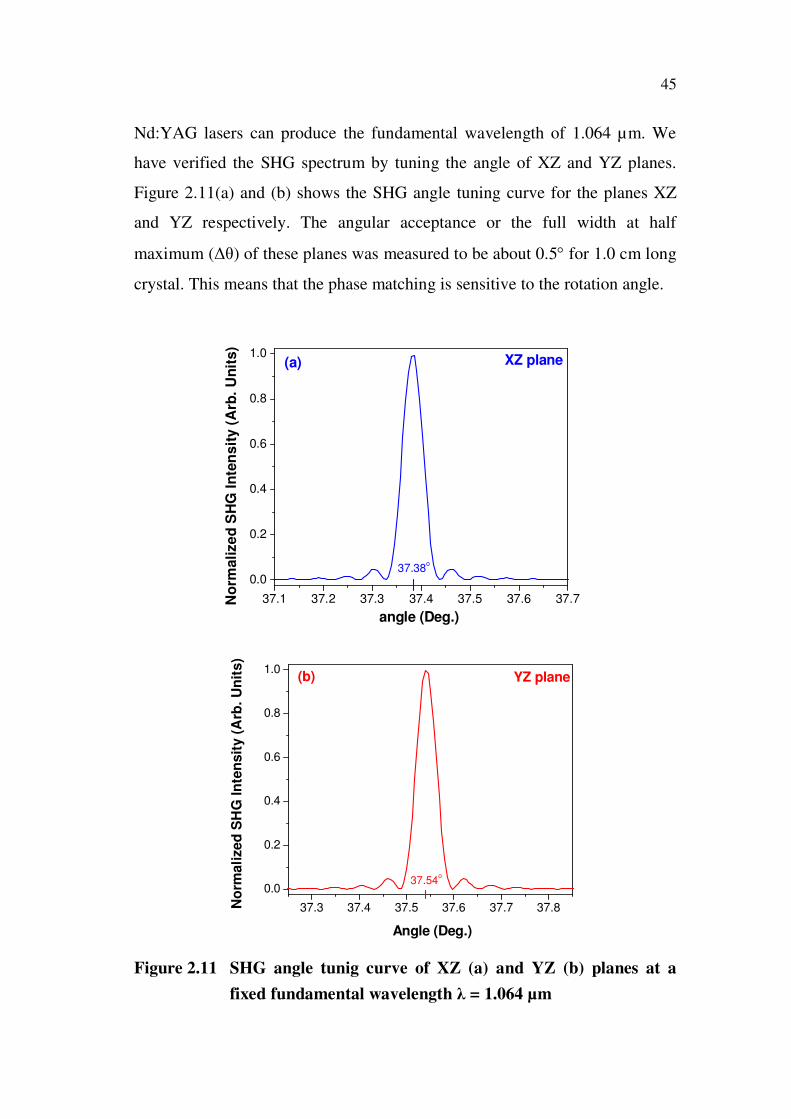
Nd:YAG lasers can produce the fundamental wavelength of 1.064 µm. We
have verified the SHG spectrum by tuning the angle of XZ and YZ planes.
Figure 2.11(a) and (b) shows the SHG angle tuning curve for the planes XZ
and YZ respectively. The angular acceptance or the full width at half
maximum ( ) of these planes was measured to be about 0.5 for 1.0 cm long
crystal. This means that the phase matching is sensitive to the rotation angle.
37.1 37.2 37.3 37.4 37.5 37.6 37.7
0.0
0.2
0.4
0.6
0.8
1.0
No
rmalize
d S
HG
In
ten
sit
y (
Arb
. U
nit
s)
angle (Deg.)
37.38o
XZ plane(a)
37.3 37.4 37.5 37.6 37.7 37.8
0.0
0.2
0.4
0.6
0.8
1.0
37.54o
YZ plane
No
rmali
zed
SH
G In
ten
sit
y (
Arb
. U
nit
s)
Angle (Deg.)
(b)
Figure 2.11 SHG angle tunig curve of XZ (a) and YZ (b) planes at a
fixed fundamental wavelength = 1.064 µm

46
2.9 WALK-OFF ANGLE
The phenomenon that the intensity distribution of a beam in an
anisotropic crystal drifts away from the direction of the wave vector is called
walk-off angle.
Figure 2.12 Schematic representation of walk-off
For a laser beam propagating in an isotropic medium, the transverse
intensity distribution propagates along the beam axis as defined by the
medium k vector. In anisotropic (and thus birefringent) crystals, this is not
necessarily the case: it can occur that the intensity distribution drifts away
from the direction defined by the k vector, as illustrated in Figure 2.12, where
the gray lines indicate wavefronts and the blue color the region with
significant optical intensity. This phenomenon, called spatial walk-off,
birefringent walk-off or Poynting vector walk-off and is associated with some
finite angle (called walk-off angle) between the Poynting vector and the k
vector. The Poynting vector defines the direction of energy transport, whereas
the k vector is normal to the wavefronts.
Spatial walk-off occurs only for a beam with extraordinary
polarization, propagating at some angle against the optical axes, so that the

47
refractive index ne and the phase velocity become dependent on that angle.
The walk-off angle (Dimitriev 1991) can then be calculated from the
equation,
( ) = ± arctan [(n n ) tan ] (2.16)
where the upper sign refer to a negative crystal and the lower sign to a
positive one. The magnitude of the walk-off angle is presented in Figure 2.13
for the LCB crystal. In typical cases, it is in the range between a few
milliradians and some tens of milliradians. For propagation directions close to
one of the axes of the index ellipsoid, the walk-off can even become much
smaller.
0.5 1.0 1.5 2.0 2.5 3.0
4
8
12
16
20
YZ plane
XZ plane
Walk
-off
An
gle
(m
rad
)
Wavelength ( m)
Figure 2.13 Spatial walk-off versus fundamental wavelength for SHG in
the principal planes of LCB
The result of the walk-off angle of LCB is also compared with
BIBO and BBO crystal. Figure 2.14 shows the walk-off of BIBO and BBO
crystal. From the comparison it is obvious that the walk-off of LCB is

48
relatively small with the commercially available and well established BIBO
and BBO crystals. For verification, at the phase matching wavelength
= 1.064 µm, the walk-off of LCB is measured to be 11 mrad, whereas BBO
and BIBO are 56 mrad and 23 mrad respectively (Valentin Petrov et al 2010).
Hence, the smaller walk-off of LCB crystal makes this as a promising
candidate for NLO application.
Figure 2.14 Spatial walk-off versus fundamental wavelength for SHG in
the principal planes of BIBO and BBO
2.10 OPTICAL PARAMETRIC OSCILLATION
An optical parametric oscillator (OPO) is a light source similar to a
laser, also using a kind of laser resonator, but based on optical gain from
parametric amplification in a nonlinear crystal rather than from stimulated
emission. Like a laser, such a device exhibits a threshold for the pump power,
below which there is negligible output power (only some parametric
fluorescence). The schematic of an OPO is shown in Figure 2.15.

49
Figure 2.15 Schematic of an optical parametric oscillator
A main attraction of OPO is that the signal and idler wavelengths,
which are determined by a phase matching condition, can be varied in wide
ranges. Thus it is possible to access wavelengths (e.g. in the mid-infrared, far-
infrared or terahertz spectral region) which are difficult or impossible to
obtain from any laser, and wide wavelength tunability is also often possible.
A limitation is that any OPO requires a pump source with high optical
intensity and relatively high spatial coherence. Therefore, a laser is essentially
always required for pumping an OPO, and as the direct use of a laser diode is
in most cases not possible, the system becomes relatively complex, consisting
a diode-pumped solid-state laser, and the actual OPO.
Parametric amplification and oscillation may be viewed upon as an
inverse sum-frequency process, for which the same phase-matching
conditions will hold; it is these phase-matching conditions that determine
which frequencies 1 and 2 will be generated at a certain setting of the angle
of the crystal with respect to the wave vector k3 of the pump beam.
k = 0 k3 = k1 + k2 (2.17)
for co-linear beams the following relation must hold in order to achieve
phase-matching:
n3 3 = n1 1 + n2 2 (2.18)

50
Of course the conservation of energy is a strict condition for
frequency conversion in an OPO (Ubachs 2001):
3 = 1 + 2 (2.19)
Again, because of dispersion in any medium these relations can
only be met under the special conditions of anisotropic crystals with a tunable
index; and again we distinguish between Type I and II phase-matching
conditions. For example:
1 and 2 are ordinary waves with index, respectively and
3 is an extraordinary wave with index ( )
So Type I phase-matched oscillation is obtained at 1 and 2 at a
specific angle = m, with the condition:
n ( ) =n + n
(2.20)
At each specific phase matching angle m the OPO will produce a
particular combination of two frequencies that obey the phase-matching
condition.
If we rotate the angle of the crystal for an amount ; so, m
m . As the pump frequency 3 is fixed at the phase-matched
frequencies will change:
1 1 + 1 (2.21)
2 2 + 2 (2.22)

51
because of energy conservation: 1= - 2. All the indices of refraction will
change:
n1 n1 + n1 (2.23)
n2 n2 + n2 (2.24)
n3 n3 + n3 (2.25)
Note that the index at the pump frequency changes, because it is an
extraordinary wave and the angle has been rotated; the index of the signal and
idler wave change because of dispersion; so the changes in the indices are:
n = frequency dependant (2.26)
n = frequency dependant (2.27)
n = angle dependance (2.28)
With these relations a new phase-matching condition has to be
satisfied, although at a different angle m :
(n3 n3 3 = (n1 n1)( 1 1) + (n2 n2)( 2 2) (2.29)
so:
n3 3 n3 3=n1 1 n1 1+n1 1 n1 1+n2 2 2 n2-n2 1 n2 1 (2.30)
Here 2=- 1 was used. With use of the original phase-matching
relation at = m and neglect of second order derivatives, such as n1 1, we
solve for:
=n n n
n n (2.31)

52
Substituting the above relations in the equation for 1 gives:
=
n n+
n
n n (2.32)
Solving 1:
= =
n
n n + [ n n
]
(2.33)
And k is written in terms of the index of refraction of an
extraordinary wave ne ). Now we use this result for the derivative n3 :
n=
1
2 n [n ( ) n ( ) ] sin 2 (2.34)
Finally, we have obtained an equation for the angle dependence of
the generated frequency of the signal wave as a function of the indices of
refraction and their dispersion relations.
=
12
n ( ) [n ( ) n ( ) ] sin 2
n n + [ n n
]
(2.35)
In an experiment with an OPO, the parameters 3 and therewith
no 3), ne 3), are constants. If the indices of the medium are known, and their
frequency dependence then the dependence of the frequency of the signal
wave 1 as a function of the angle may be calculated numerically, using the
above equation. Such an angle tuning curve for an OPO based LCB crystal
shown in the Figure 2.16. The wavelength of both the signal and the

53
corresponding idler (energy conservation) at the particular easily accessible
pump wavelength of 0.355 µm is shown.
Figure 2.16 The calculated phase matching for type I OPO processes in
LCB for propagation in the principal refractive-index
planes XZ (a) and YZ (b). Pump wavelength = 0.355 µm
36 39 42 45 48 51 54
0.5
1.0
1.5
2.0
2.5
3.0
3.5
Idler i
Signal s
Wa
ve
len
gth
(m
)
Angle (Deg.)
Pump p = 0.355 mXZ plane(a)
36 39 42 45 48 51 54
0.5
1.0
1.5
2.0
2.5
3.0
3.5
Wa
ve
len
gth
(m
)
Angle (Deg.)
Idler i
Signal s
Pump p = 0.355 mYZ plane(b)

54
Thus it is observed that a device, an OPO based on the material
LCB, and pumped by the UV-output of a Nd-YAG laser, is a source for
coherent radiation in the wavelength range 0.4 - 3.2 µm, this means the whole
visible and near infrared part of the spectrum (wavelengths longer than 3.2
µm are absorbed in the LCB crystal). And the tuning of such a device may be
simply arranged by rotating the crystal over an angle from 37 to 55 degrees in
both the planes.
2.11 CONCLUSION
We theoretically analysed the nonlinear optical properties of LCB
crystal. The change in refractive indices with respect to the wavelength for the
entire transparency region was plotted using a Sellmeier equation to check the
phase matching property of the crystal. The indices were nx<ny<nz, at the
same time nx and ny were close to each other, due to this behavior phase
matchable region was limited in the XY plane. Hence, for our theoretical
study XZ and YZ planes have been taken. SHG, spatial walk-off and OPO
for these planes were studied. The phase matching angle for Type - I
frequency doubling of fundamental wavelength = 1.064 µm was calculated
to be 37.38 and 37.54 respectively. The angular acceptance ( ) of these
planes was measured to be about 0.5 for 1.0 cm long crystal. The spatial
walk-off was compared with the well established crystals like BBO and
BiBO. It was about 11 mrad for LCB crystal of fundamental wavelength
= 1.064 µm, whereas BBO and BiBO were 56 mrad and 23 mrad
respectively. Hence, the smaller walk-off makes LCB as a promising
candidate for NLO application. In addition to this, the investigation on OPO
characteristics of the LCB crystal of input pump 0.355 µm for the wavelength
range 0.4 – 3.2 µm was calculated, and the tuning of such a device was
calculated to be rotating the crystal over an angle from 37 to 55 degrees in
both the planes.