chapter 22 cardiac defibrillators
TRANSCRIPT
Chapter 22
CARDIAC DEFIBRILLATORS
OBJECTIVES
State the clinical applications of cardiac defibrillation. Sketch the damped sinusoidal, truncated exponential, and biphasic defibrillation waveforms, and analyze the basic circuits to generate such waveforms.
Draw a block diagram of a cardiac defibrillator and explain the func-tions of each block.
Describe built-in safety features, including isolated output and energy dump.
Identify and explain the functions of critical components in a typical defibrillator.
Explain synchronous cardioversion and its operating precautions. Identify common problems of cardiac defibrillators and methods to
prevent the problems.
CHAPTER CONTENTS
1. Introduction 2. Principles of Defibrillation 3. Defibrillation Waveforms 4. Waveform Shaping Circuits
5. Functional Building Blocks of Defibrillators 6. Output Isolation and Energy Dumping 7. Cardioversion 8. Defibrillator Operation and Quality Assurance
9. Common Problems
355
Biomedical Device Technology: Principles and Design
INTRODUCTION
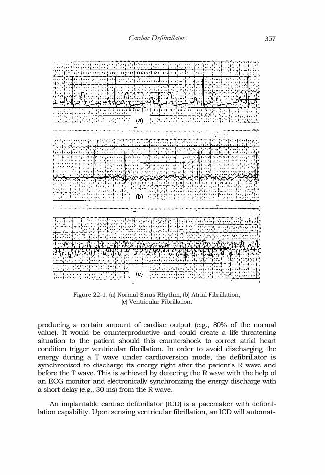
Fibrillation is an arrhythmia. During fibrillation, the heart muscle quiv-ers randomly and erratically as a result of individual groups of heart muscle contracting randomly instead of synchronously. If fibrillation occurs at the ventricles, it is called ventricular fibrillation. This situation is life-threatening as it prevents effective pumping of blood to vital organs such as the brain, lungs, and the heart itself. If it occurs at the atria, it is called atrial fibrillation. Atrial fibrillation is less severe and in most cases is not fatal. However, it compromises cardiac output and will likely lead to other more severe arrhythmias. Figure 22-1 shows a normal sinus rhythm, atrial fibrillation, and ventricular fibrillation waveforms.
Prevost and Batelli in 1899 proved that an "appropriate" large, alternat-ing current (AC) or direct current (DC) electric shock could reverse ventric-ular fibrillation. It was not until 1960 that open-chest defibrillation was replaced by the external defibrillation method. Today, the defibrillator is a critical life-saving medical device that is widely deployed in hospitals, clin-ics, ambulances, and even in public areas to treat sudden cardiac arrest.
PRINCIPLES OF DEFIBRILLATION
Fibrillation can be caused by disruption of the electroconductive path-ways in the myocardial muscle such as the SA or AV nodes. It may also be triggered by an electrical shock. Passing a very large momentary electrical current through the heart causes all musculature of the heart to be depolar-ized for a short period of time and enter their refractory period together. This gives the SA node a chance to regain control and return to normal rhythm. Defibrillation can be external or internal. During defibrillation, an ECG monitor is necessary to detect ventricular fibrillation and thereafter monitor the heart function until the patient can be placed in a critical care environ-ment. When defibrillation is applied externally on the patient, a larger volt-age (and higher energy) is required to overcome the impedance of the body and to allow enough current to go through the heart. A typical discharge energy range is from 2 to 40 joules for internal defibrillation and 50 to 400 joules for external defibrillation.
Defibrillators/monitors can also be used for synchronized cardioversion to treat certain atrial arrhythmias such as atrial flutter or atrial fibrillation. An electrical shock applied to a nonfibrillating heart during the T wave of the heart rhythm may trigger ventricular fibrillation. During atrial flutter or atrial fibrillation, the ventricles can still contract at regular intervals,
therefore
356
357 Cardiac Defibrillators
Figure 22-1. (a) Normal Sinus Rhythm, (b) Atrial Fibrillation, (c) Ventricular Fibrillation.
producing a certain amount of cardiac output (e.g., 80% of the normal value). It would be counterproductive and could create a life-threatening situation to the patient should this countershock to correct atrial heart condition trigger ventricular fibrillation. In order to avoid discharging the energy during a T wave under cardioversion mode, the defibrillator is synchronized to discharge its energy right after the patient's R wave and before the T wave. This is achieved by detecting the R wave with the help of an ECG monitor and electronically synchronizing the energy discharge with
a short delay (e.g., 30 ms) from the R wave.
An implantable cardiac defibrillator (ICD) is a pacemaker with defibril-lation capability. Upon sensing ventricular fibrillation, an ICD will automat-
358 Biomedical Device Technology: Principles and Design
ically produce a shock to the heart. An ICD can be programmed to provide defibrillation, cardioversion, antitachycardia pacing, and antibradycardia pacing.
Studies since its initial conception indicated that numerous factors can affect the effectiveness of the defibrillation procedure. These include the waveform, energy and amplitude of the electric shock, the electrode position, and interface impedance, as well as the size and weight of the patient.
DEFIBRILLATION WAVEFORMS
Early experimental defibrillators used 60 Hz alternating current (AC) and a step-up transformer to create and increase the defibrillation voltage. Bursts of several hundred volts of sine wave were applied across the chest wall for a period of 0.25 to 1 second. The desire for portability led to the development of direct current (DC) defibrillators. A DC defibrillator uses a battery as the power source so that connection to the AC outlet is not required during defibrillation. The battery may be replaced or recharged after use. It was later discovered that DC shocks were more effective than AC shocks. Until recently, defibrillators have used one of the two types of monophasic waveforms: damped sinusoidal (MD S) and monophasic trun-cated exponential (MTE). The MDS waveform is also called the Lown wave-form. Figure 22-2 shows a typical MDS and MTE defibrillation waveform. Note that the typical MDS waveform has a small negative component; there-fore, strictly speaking, it is not truly monophasic.
Monophasic waveforms require a high energy level (up to 360J) to defib-rillate effectively. A MDS waveform requires a high peak voltage (e.g., 5,000 V) to deliver such energy. The MTE waveform uses similar energy settings. However, it uses a lower voltage than the MDS waveform. In order to deliver the same amount of energy, the MTE waveform requires a longer duration. While studies had associated myocardium damages with high peak voltages, long-duration shocks have higher chances of refibrillation.
Studies in the early 1990s had shown that biphasic defibrillation wave-forms are more effective than monophasic waveforms. In fact, the biphasic waveform has been the standard waveform for an implantable cardiac defib-rillator (ICD) since it was introduced. With biphasic waveforms, the defibril-lation current passes through the heart in one direction and then in the reverse direction. A number of biphasic waveforms are incorporated by dif-ferent defibrillator manufacturers. Figure 22-3 shows one such waveform. Studies have shown that defibrillations using biphasic waveforms not only defibrillate as well as traditional monophasic waveforms but also are associ-ated with better postshock cardiac function, fewer postshock arrhythmias,

Cardiac Defibrillators
Figure 22-2. Monophasic Defibrillation Waveforms.
and better neurological outcomes for survivors. In addition, biphasic defib-rillators at lower energy settings have been shown to produce the same results as traditional high energy monophasic defibrillators. One manufac-turer recommends that escalating energy shock protocols traditionally used in monophasic defibrillation are not required in monophasic defibrillation. Instead, a setting of 150J is recommended to be used for the first and all sub-sequent shocks.
Figure 22-3. Biphasic Defibrillation Waveforms.
359
Biomedical Device Technology: Principles and Design
WAVEFORM SHAPING CIRCUITS
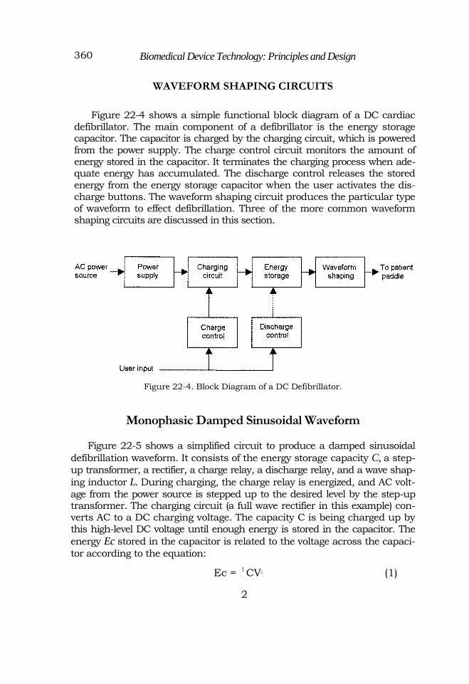
Figure 22-4 shows a simple functional block diagram of a DC cardiac defibrillator. The main component of a defibrillator is the energy storage capacitor. The capacitor is charged by the charging circuit, which is powered from the power supply. The charge control circuit monitors the amount of energy stored in the capacitor. It terminates the charging process when ade-quate energy has accumulated. The discharge control releases the stored energy from the energy storage capacitor when the user activates the dis-charge buttons. The waveform shaping circuit produces the particular type of waveform to effect defibrillation. Three of the more common waveform shaping circuits are discussed in this section.
Figure 22-4. Block Diagram of a DC Defibrillator.
Monophasic Damped Sinusoidal Waveform
Figure 22-5 shows a simplified circuit to produce a damped sinusoidal
defibrillation waveform. It consists of the energy storage capacity C, a step-
up transformer, a rectifier, a charge relay, a discharge relay, and a wave shap-
ing inductor L. During charging, the charge relay is energized, and AC volt-
age from the power source is stepped up to the desired level by the step-up transformer. The charging circuit (a full wave rectifier in this example) con-verts AC to a DC charging voltage. The capacity C is being charged up by this high-level DC voltage until enough energy is stored in the capacitor. The
energy Ec stored in the capacitor is related to the voltage across the capaci-
tor according to the equation:
Ec = —
1 CV2. (1)
2
360
361 Cardiac Defibrillators
The voltage across the capacitor is monitored to determine the amount of energy stored. The charge relay is deenergized when sufficient energy is stored in the capacitor. When the operator pushes the discharge buttons, the discharge relay is energized. The energy stored in the
capacitor flows through the inductor L into the patient. For ease of
analysis, the patient load R is considered to be a resistive load of 50 Ω.
The current discharging through this LRC circuit produces the damped sinusoidal waveform (Figure 22-2a).
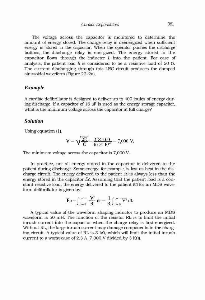
Example
A cardiac defibrillator is designed to deliver up to 400 joules of energy dur-ing discharge. If a capacitor of 16 µF is used as the energy storage capacitor,
what is the minimum voltage across the capacitor at full charge?
Solution
Using equation (1),
The minimum voltage across the capacitor is 7,000 V.
In practice, not all energy stored in the capacitor is delivered to the patient during discharge. Some energy, for example, is lost as heat in the dis-charge circuit. The energy delivered to the patient ED is always less than the
energy stored in the capacitor Ec. Assuming that the patient load is a con-
stant resistive load, the energy delivered to the patient ED for an MDS wave-form defibrillator is given by:
A typical value of the waveform shaping inductor to produce an MDS waveform is 50 mH. The function of the resistor RL is to limit the initial inrush current into the capacitor when the charge relay is first energized. Without RL, the large inrush current may damage components in the charg-ing circuit. A typical value of RL is 3 kΩ, which will limit the initial inrush
current to a worst case of 2.3 A (7,000 V divided by 3 KΩ).

362 Biomedical Device Technology: Principles and Design
Figure 22-5. Simple MDS Defibrillator Circuit.
Monophasic Truncated Exponential Waveform
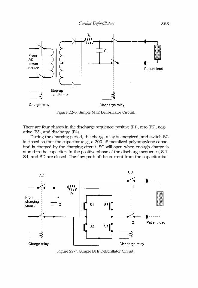
Figure 22-6 shows a simplified circuit of a monophasic truncated expo-nential waveform defibrillator. This circuit is identical to the circuit described above except that there is no waveform shaping inductor in the discharge cir-cuit. A typical value of the energy storage capacitor is 200 µF. Without the
inductor, the discharge circuit is an RC instead of a LRC circuit where R is the patient load. An RC discharge will produce an exponential decay curve (Figure 22-2b). Instead of allowing sufficient time to discharge all energy stored in the energy storage capacitor, a MTE defibrillator will terminate the discharge when enough energy is delivered to the patient. During defibrilla-tion, the voltage across the paddles is monitored and the amount of energy discharged into the patient ED is determined by:
Biphasic Truncated Exponential Waveform
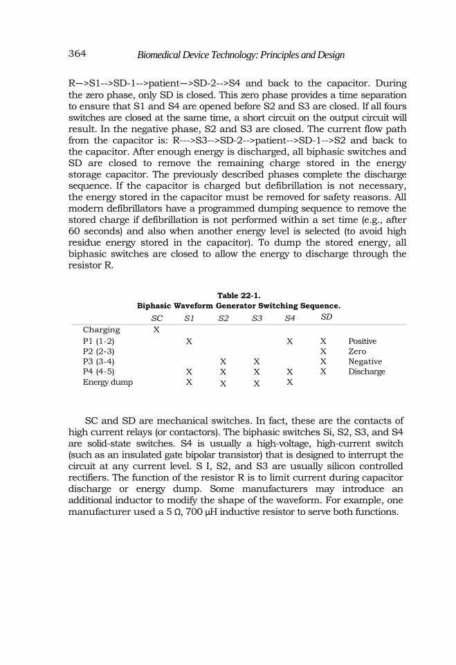
Figure 22-7 shows a simplified circuit of a biphasic truncated exponen-tial waveform generator. A bank of switches is added to the previously described MTE circuit. By closing and opening the biphasic switches S1 to S4, a biphasic waveform (Figure 22-3) is produced. Table 22-1 shows the switching sequence of the switches and relays for the charging, discharging, and energy dumping functions. In the table, an "X" denotes switch closure.
363 Cardiac Defibrillators
Figure 22-6. Simple MTE Defibrillator Circuit.
There are four phases in the discharge sequence: positive (P1), zero (P2), neg-ative (P3), and discharge (P4).
During the charging period, the charge relay is energized, and switch SC is closed so that the capacitor (e.g., a 200 µF metalized polypropylene capac-
itor) is charged by the charging circuit. SC will open when enough charge is stored in the capacitor. In the positive phase of the discharge sequence, S 1, S4, and SD are closed. The flow path of the current from the capacitor is:
Figure 22-7. Simple BTE Defibrillator Circuit.
Biomedical Device Technology: Principles and Design
R—>S1-->SD-1-->patient—>SD-2-->S4 and back to the capacitor. During
the zero phase, only SD is closed. This zero phase provides a time separation to ensure that S1 and S4 are opened before S2 and S3 are closed. If all fours switches are closed at the same time, a short circuit on the output circuit will result. In the negative phase, S2 and S3 are closed. The current flow path from the capacitor is: R--->S3-->SD-2-->patient-->SD-1-->S2 and back to the capacitor. After enough energy is discharged, all biphasic switches and SD are closed to remove the remaining charge stored in the energy storage capacitor. The previously described phases complete the discharge sequence. If the capacitor is charged but defibrillation is not necessary, the energy stored in the capacitor must be removed for safety reasons. All modern defibrillators have a programmed dumping sequence to remove the stored charge if defibrillation is not performed within a set time (e.g., after 60 seconds) and also when another energy level is selected (to avoid high residue energy stored in the capacitor). To dump the stored energy, all biphasic switches are closed to allow the energy to discharge through the resistor R.
Table 22-1.
Biphasic Waveform Generator Switching Sequence.
SC S1 S2 S3 S4 SD Charging X P1 (1-2) X X X Positive P2 (2-3) X Zero P3 (3-4) X X X Negative P4 (4-5) X X X X X Discharge Energy dump X X X X
SC and SD are mechanical switches. In fact, these are the contacts of high current relays (or contactors). The biphasic switches Si, S2, S3, and S4 are solid-state switches. S4 is usually a high-voltage, high-current switch (such as an insulated gate bipolar transistor) that is designed to interrupt the circuit at any current level. S I, S2, and S3 are usually silicon controlled rectifiers. The function of the resistor R is to limit current during capacitor discharge or energy dump. Some manufacturers may introduce an additional inductor to modify the shape of the waveform. For example, one
manufacturer used a 5 Ω, 700 µH inductive resistor to serve both functions.
364

Cardiac Defibrillators
FUNCTIONAL BUILDING BLOCKS OF DEFIBRILLATORS
Figure 22-8 shows the functional block diagram of a DC defibrillator. After the user selects the energy setting and pushes the charge button, the charge control circuit energizes the charge relay. The voltage across the energy storage capacitor is monitored during charging. Using equation (1), the charge relay is deenergized when the voltage across the capacitor is equal to the voltage corresponding to the selected defibrillation energy level. The charging sequence is then completed. The discharge relay is energized once the user pushes the discharge buttons on the defibrillator paddles (both buttons, one on each paddle, must be activated to prevent inadvertent discharge). The energy stored in the capacitor is then released through the waveform shaping circuit to the patient's chest to perform defibrillation. The energy being delivered to the patient is determined by the
voltage and current monitors (ED = V X I x t). When the total delivered
energy has reached the user selected value, the discharge relay is deenergized.
Figure 22-8. Functional Block Diagram of a DC Defibrillator.
Due to portability requirements, an internal rechargeable battery is used as the primary energy source of DC defibrillators. The capacity of a fully charged battery is usually sufficient to perform 20 to 80 defibrillation dis-charges. Defibrillators are always plugged into the AC mains on standby. AC voltage is rectified to charge the battery. When fully charged, the battery
365

Biomedical Device Technology: Principles and Design
charge is maintained using a trickle charge system. During the charging phase, the low-voltage D C from the battery is first converted to a high-fre-quency (e.g., 25 kHz) AC voltage by an inverter. This AC voltage is then stepped up to a higher voltage, say, 7,000 V, and rectified to charge the energy storage capacitor. The functional block diagram of the power supply and charging circuit is shown in Figure 22-9.
Figure 22-9. Defibrillator Power Supply and Charging Circuit.
OUTPUT ISOLATION AND ENERGY DUMPING
A defibrillator produces an electrical shock on the patient to correct heart arrhythmia. If during the delivery of an electrical shock, the operator inad-vertently touches the discharge paddles or the patient, the shock may cause burns or trigger ventricular fibrillation to the operator. Such injuries to the operator can be prevented by isolating the output of the defibrillator from ground. Figure 22-10a shows a nonisolated defibrillator output circuit. When an operator who has a ground connection is in contact with the output while the energy is discharged, a current will flow through the operator to ground and return to the energy storage capacitor. Figure 22-10b shows an isolated defibrillator output circuit. During shock delivery, the energy storage capac-itor is not connected to ground. Theoretically, even when the operator is touching a defibrillator paddle, no current will flow through the operator as there is no return path for such current. In practice, however, a small current still flows through the operator.
Isolated output can also prevent secondary burn to the patient. For a grounded output circuit, a secondary burn occurs when the patient is in con-
366

Cardiac Defibrillators
tact with ground; such ground connection will provide an alternative return path for the discharge current. It will cause a burn at the ground contact site if sufficient current flows through this patient ground path.
After the energy storage capacitor is charged, if no defibrillation is nec-essary after a period of time, the charge in the capacitor will be dumped through a high power resistor. This is a safety feature to ensure that no haz-ardous high voltage is present in the unit for the safety of the users. In addi-tion, if another energy level is selected, the charge stored in the capacitor will be released before it receives its new charge. This is to prevent accumulation of charge in the capacitor, especially if the new selection is of lower energy.
367
Figure 22-10. (a) Nonisolated Output, (b) Isolated Output.

Biomedical Device Technology: Principles and Design
CARDIOVERSION
Cardiac defibrillators are useful in correcting ventricular fibrillation. However, the defibrillation shock may trigger ventricular fibrillation in a healthy heart. During atrial fibrillation or atrial flutter, only the atrial muscle is contracting erratically. Studies have shown that a defibrillation pulse applied during the refractory period (T wave) of the ventricles may induce other more severe arrhythmias such as ventricular fibrillation. Therefore, a synchronization circuit is required in cardioversion to avoid such complica-
tions.
The window of discharge for safe cardioversion is immediately after the QRS complex and before the T wave. A cardioversion synchronizing circuit consists of an R wave detector and a time delay circuit to synchronize the dis-charge within this safety window (Figure 22-11). An enabling signal is sent to the discharge control about 30 ms after detection of the R wave. When the synchronous cardioversion feature is selected, care should be taken to check whether the machine is able to lock onto the R wave (usually, successful detection of the R wave is highlighted on the ECG display). The user may have to increase the ECG sensitivity level to provide sufficient R wave amplitudes for the R wave detector to lock onto the signal.
Figure 22-11. Cardioversion Synchronous Module.
DEFIBRILLATOR OPERATION AND QUALITY ASSURANCE
The procedures for safe operation of a cardiac defibrillator are:
1. Apply electrolyte gel to the defibrillator paddles (for better patient electrical contact and to reduce risk of burn by lowering the skin resistance).
2. Set energy level and press the charge button. 3. Allow capacitor to charge until a ready signal is given.
4. Press the paddles against the patient's chest. 5. Clear the patient area. 6. Press the defibrillator discharge buttons.
7. Check the patient's ECG waveform.
368

Cardiac Defibrillators
8. Repeat the above procedures if no sinus rhythm is detected (usually
with a higher energy setting).
Because a defibrillator delivers a high-voltage therapeutic pulse to criti-cally ill patients, reliability of the device is crucial. A defibrillator should be tested regularly to ensure its performance. Most hospitals require daily user testing. Depending on the hospital's protocol, testing includes functional checks and may include checking for correct energy delivery. Often, exten-sive performance verifications, including battery capacity and defibrillation energy accuracy, are done periodically (e.g., every 3 months) by biomedical engineering personnel. When not in use, a defibrillator should always be plugged into the AC wall outlet to ensure that the internal battery is charged and ready for use.
COMMON PROBLEMS
Problems with defibrillators can be divided into two groups: hardware
problems and operational problems.
Hardware Problems
Batteries are considered as high-maintenance components in a defib-rillator. Failure of batteries prevents successful defibrillation, causing death. Common battery problems include battery not fully charged, battery failure, and cell memory failure in some batteries. Common batteries used in defibrillator are nickel-cadmium (NiCad), sealed lead acid, and nickel metal hydride (NiMH).
Electronic components in general are quite reliable. Due to the need to deliver high-energy discharge pulses, relay
failure is not uncommon in defibrillators. Relay contacts (especially the discharge relay) may be pitted from arcing which creates high resistance at the contact; or fused due to excessive heat from high discharge current.
Common problems with the energy storage capacitor are excessive leakage (which prevents the capacitor from maintaining the energy level), and short circuit due to insulation breakdown.
Hardware problems can be prevented by periodic performance assur-
ance inspections and battery analysis.
369

Biomedical Device Technology: Principles and Design
Operational Problems
Users not familiar with the operation of the defibrillator
Incorrect application of conductive gel, causing high paddle-skin resis-tance; high current density; or current shunt path, which may lead to
unsuccessful defibrillation or patient injuries
Incorrect paddle placement resulting in current not passing through the heart
Electrical shock to staff from gel spill, staff touching patient, or staff touching paddles
Most user errors can be prevented by proper in-service training, periodic practice, and equipment standardization.
Problem Unique to Synchronous Cardioversion
Unit not picking up R wave properly (missing or too low R wave level due to poor skin contact or too low sensitivity setting)
To prevent problems or hazards, the following must be done by the users
regularly:
Receive proper user in-service training.
Perform operational check by charging and discharging into dummy load (e.g., weekly).
Plug unit into wall outlet to maintain battery charge when not in use.
Clean unit, especially paddles, after every use to prevent dried gel and dirt from building up.
Check quantities and expiration dates of all supplies (e.g., conductive gel, ECG electrodes) that are with the unit.
Send unit periodically to biomedical engineering for complete func-tional and calibration check.
370