chapter 3. design, construction and operation of landfill gas
TRANSCRIPT

International Best Practices Guide for LFGE Projects – 2012
3. Design, Construction and Operation of Landfill Gas Collection and Control Systems 21
The basis of any LFGE project involves the design, construction and operation of an LFG collection and control system (GCCS). The purpose of a GCCS is to extract LFG from the waste mass and convey it to a combustion device for flaring or energy use. A typical GCCS includes the following primary components: extraction wells; a system of lateral and header (manifold) piping to convey the collected LFG; a condensate management system; a blower and flare system; monitoring devices; and system controls.
This chapter discusses the concepts and considerations for the design, construction and operation of a GCCS. These systems require proper engineering design, construction and operation by trained personnel to operate and meet the needs of an LFG project and maximize intended benefits. In general, maximizing collection efficiency (when the LFG collection rate approaches the LFG generation rate) will improve environmental benefits such as greenhouse gas (GHG) emissions and odor control, while also improving economic return where project revenue depends on LFG collection (such as for energy utilization).
3.1 GCCS Design
Overall GCCS design is based on expected LFG collection, the type and depth of the waste, SWD site conditions and operating status (open or closed), and the overall goals of the LFG project. During the construction phase, use of proper techniques and quality assurance procedures is needed to ensure proper system operation and reliability. Finally, operation of these systems determines the success of the LFG project. Periodic monitoring and adjustments must be made to the GCCS as SWD site conditions constantly change. Changing SWD site conditions are caused by waste filling at open sites, degradation of organic material, settlement of the waste mass and weather conditions. The sections below provide more detail on design, construction and operation of a GCCS.
Extraction Wells
Gas collection begins in the extraction wells, where LFG is extracted from the waste mass and enters the GCCS. Extraction wells are typically composed of slotted plastic pipe, surrounded by stone or other aggregate material, that are installed in borings in the waste mass below the surface of the SWD site. Above the surface of the waste mass, the extraction well typically has a wellhead to allow for vacuum adjustment and sampling of the LFG. The orientation of these wells can either be vertical or horizontal, and the decision to use vertical and or horizontal wells will depend on site-specific factors and goals of the LFG project.
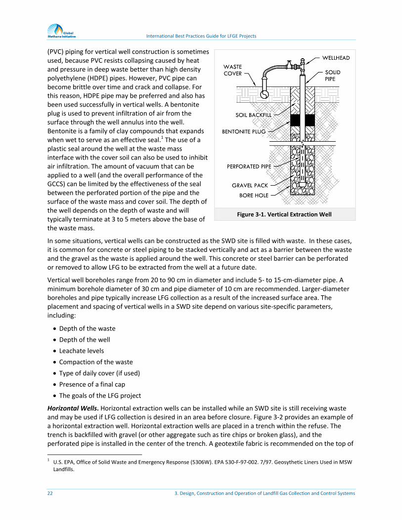
Vertical Wells. Vertical wells are usually installed in areas where the site has stopped receiving waste or where waste filling will not occur for a year or more. However, they can be installed and operated in areas with continued waste placement, but placement will result in increased operation and maintenance requirements. Figure 3-1 provides an example of a vertical extraction well.
The components of a vertical well include the well piping with perforations or slots at the bottom portion of the pipe, clean gravel backfill, soil backfill, a bentonite plug and a wellhead. Polyvinyl chloride
Training Opportunities
Skilled and appropriately trained personnel are needed to operate a GCCS. GMI offers training opportunities on operations of landfills and LFG systems. Visit their website to learn about upcoming training opportunities.
International Best Practices Guide for LFGE Projects
22 3. Design, Construction and Operation of Landfill Gas Collection and Control Systems
(PVC) piping for vertical well construction is sometimes used, because PVC resists collapsing caused by heat and pressure in deep waste better than high density polyethylene (HDPE) pipes. However, PVC pipe can become brittle over time and crack and collapse. For this reason, HDPE pipe may be preferred and also has been used successfully in vertical wells. A bentonite plug is used to prevent infiltration of air from the surface through the well annulus into the well. Bentonite is a family of clay compounds that expands when wet to serve as an effective seal.1 The use of a plastic seal around the well at the waste mass interface with the cover soil can also be used to inhibit air infiltration. The amount of vacuum that can be applied to a well (and the overall performance of the GCCS) can be limited by the effectiveness of the seal between the perforated portion of the pipe and the surface of the waste mass and cover soil. The depth of the well depends on the depth of waste and will typically terminate at 3 to 5 meters above the base of the waste mass.
In some situations, vertical wells can be constructed as the SWD site is filled with waste. In these cases, it is common for concrete or steel piping to be stacked vertically and act as a barrier between the waste and the gravel as the waste is applied around the well. This concrete or steel barrier can be perforated or removed to allow LFG to be extracted from the well at a future date.
Vertical well boreholes range from 20 to 90 cm in diameter and include 5- to 15-cm-diameter pipe. A minimum borehole diameter of 30 cm and pipe diameter of 10 cm are recommended. Larger-diameter boreholes and pipe typically increase LFG collection as a result of the increased surface area. The placement and spacing of vertical wells in a SWD site depend on various site-specific parameters, including:
Depth of the waste
Depth of the well
Leachate levels
Compaction of the waste
Type of daily cover (if used)
Presence of a final cap
The goals of the LFG project
Horizontal Wells. Horizontal extraction wells can be installed while an SWD site is still receiving waste and may be used if LFG collection is desired in an area before closure. Figure 3-2 provides an example of a horizontal extraction well. Horizontal extraction wells are placed in a trench within the refuse. The trench is backfilled with gravel (or other aggregate such as tire chips or broken glass), and the perforated pipe is installed in the center of the trench. A geotextile fabric is recommended on the top of
1 U.S. EPA, Office of Solid Waste and Emergency Response (5306W). EPA 530-F-97-002. 7/97. Geosythetic Liners Used in MSW
Landfills.
Figure 3-1. Vertical Extraction Well

International Best Practices Guide for LFGE Projects
3. Design, Construction and Operation of Landfill Gas Collection and Control Systems 23
the trench to reduce clogging of the aggregate by the backfill or trash above. Common spacing of horizontal wells is 30 to 40 meters apart. The perforated pipe within the trench is typically 10 to 20 cm in diameter.
The overall goals of the LFG project also should be considered when the placement of extraction wells is planned. For the case of meeting regulatory requirements or significant environmental mitigation issues, a GCCS designer may include additional components to achieve greater emissions control (as an example) even though these collectors may not be cost effective for energy use purposes. However, if an LFG project is being implemented for economic reasons, such as a GHG emission reduction project or for energy use, the extent of well coverage on the SWD site may be prioritized based on economic considerations.
Landfill operations and the overall goals for the GCCS will determine whether vertical or horizontal wells, or both, will be used. Table 3-1 summarizes some general advantages and disadvantages of vertical and horizontal wells, setting aside landfill-specific operations.
Table 3-1. Advantages and Disadvantages of Vertical and Horizontal LFG Collection Wells
Vertical Wells Horizontal Wells
Advantages Disadvantages Advantages Disadvantages
Minimal disruption of landfill operations if placed in closed area of landfill
Most common design
Reliable and accessible for inspection and pumping
Increased operation and maintenance required if installed in active area of landfill
Availability of appropriate equipment
Delayed gas collection if installed after site or cell closes
Facilitates earlier collection of LFG
Reduced need for specialized construction equipment
Allows extraction of gas from beneath an active tipping area on a deeper site
Increased likelihood of air intrusion until sufficiently covered with waste
More prone to failure because of flooding or landfill settlement
Figure 3-2. Horizontal Extraction Well
Example: Consider Costs When Placing Extraction Wells
Shallow wells will collect less LFG on a per-well basis than deeper wells and will require denser spacing to achieve comprehensive LFG collection in shallow areas of waste mass. As a result, there may be increased capital and operating costs for smaller levels of LFG collection. Therefore, if economics are a primary consideration, a GCCS designer may choose not to install some shallower wells to minimize costs.

International Best Practices Guide for LFGE Projects
24 3. Design, Construction and Operation of Landfill Gas Collection and Control Systems
Wellhead Components
Wellheads are typically found on the extraction wells above the surface to allow for vacuum adjustment and sampling of the LFG. There are several components of a LFG wellhead: a vacuum control valve; monitoring ports; and an option for flow measurement. The vacuum control valve allows an LFG technician to adjust the vacuum applied at each individual wellhead. The wellhead is often designed with one or two monitoring ports so an LFG technician can measure the temperature, pressure, and composition of the LFG. These ports allow an LFG technician to record the impacts of well adjustments and to identify potential problems and troubleshoot errors that may occur in the GCCS. Frequent wellhead monitoring promotes optimal system operation and allows for effective system maintenance. In addition, wellheads can include a flow measurement device (for example, an orifice plate or pitot tube) to measure the differential pressure of the LFG and use those figures to calculate the LFG flow. The top of the wellhead should include a removable cap to access the well for internal inspection and measure and remove liquids as necessary. High levels of liquid (leachate) in a well can reduce LFG collection, especially if the liquid level is above the perforated pipe section of the well, preventing the gas from moving into the well.
Lateral and Header Piping
Lateral and header piping are installed to transport LFG from the individual wells to the blower and flare system. LFG piping should be designed to accommodate the necessary volume of LFG, minimize vacuum loss and provide consistent vacuum to the individual wells. Lateral pipes connect each well to larger header pipes. Header pipes aggregate the LFG collected and transported in the lateral pipes.
The lateral and header piping system should be designed to accommodate the maximum expected LFG flow rates to minimize future upgrades if LFG collection continues to increase. Pipe sizing should also consider vacuum loss caused by friction and the avoidance of pipe blockage by allowing LFG flow to continue despite moderate condensate build up that results from sagging and in areas where waste can settle.
LFG piping may be installed above the surface or below the surface. Table 3-2 identifies some general advantages and disadvantages for each approach.
Table 3-2. Advantages and Disadvantages of Installing LFG Piping Above or Below Ground Surface
Above Surface Below Surface
Advantages Disadvantages Advantages Disadvantages
Reduced system costs in areas where freezing does not occur, interim or final cover has been installed, and scavengers do not have access
Increased ability to inspect, repair and upgrade the piping system
Pipes must be protected against weather effects and movement from thermal expansion or contraction, which may result in more frequent cracks and weld separations
More difficult maintenance of the waste mass surface or cover (such as grass mowing)
Can result in lower operating costs
May be more visually appealing than above-surface piping
More expensive to install
Figure 3-3. Wellhead

International Best Practices Guide for LFGE Projects
3. Design, Construction and Operation of Landfill Gas Collection and Control Systems 25
Condensate Management
Condensate refers to the moisture or liquid that is formed when extracted LFG cools. There are many factors that affect the quantity of condensate generated in a GCCS, including the LFG temperature and volume. In addition, the climate conditions at the site also can influence the amount of moisture formed in the LFG. As LFG is collected from the waste mass, it cools and has a reduced ability to hold moisture in a vapor form. The condensation that forms can restrict or completely block the flow of LFG in the piping system. The GCCS must be carefully designed to consider condensate management issues to prevent negative impacts on LFG collection.
The lateral and header systems should be designed to facilitate condensate drainage to low points, where it can be removed from the system by vacuum-sealed sump pumps or allowed to drain back into the waste mass. Typically, a minimum slope of 3 to 5 percent will facilitate condensate drainage even if pipe settlement occurs. If drained back into the waste mass, the condensate low point must include a vacuum trap to prevent air from being drawn into the header. The trap must provide a sufficient vacuum break to match the maximum expected applied vacuum on the system (plus a safety factor).
Once the LFG is collected from the waste mass, it is necessary to treat it to remove moisture and particulates. The removal of moisture and particulates is necessary to reduce the abrasive and corrosive nature of the raw LFG to protect the blower and ensure the LFG will burn effectively in a flare or other combustion device. Particulates are typically removed through the use of filtration. The most common device for moisture control is a moisture separator (sometimes referred to as a knock-out pot), which is a large cylindrical vessel that reduces the velocity of the LFG to allow entrained moisture to fall out of the LFG. A mist eliminator is often used to further remove moisture and other particulates in the LFG. A mist eliminator can be a wire-mesh or plastic-mesh screen through which the LFG passes and collects droplets of water that were too small to be collected by the moisture separator. The wire-mesh screen is subject to potential corrosion. This system also screens out other particulates that the LFG may contain.
Typical condensate management systems will pump the liquids collected by sumps to one or more storage tanks to house the condensate until it can be treated, reused or disposed of. Collected condensate is typically combined with leachate for treatment or disposal.
Blower and Flare Skid
The blower and flare skid is a critical part of the GCCS. The blower provides the vacuum used to collect LFG from the waste mass. It also provides the necessary pressure to push the LFG to the flare or to an energy use device. A flare system is used to combust the LFG and in many cases is required to control odors or mitigate other environmental or health concerns. If possible, the blower and flare system should be centrally located near the LFG collection system or near the energy use device. The flare systems should be installed away from any trees, power lines, or other objects that could be ignited by the flame or damaged by heat.
Once the LFG has been treated, it then flows to the blower where the vacuum at the inlet is adjusted to meet the requirements of the GCCS and the outlet pressure of the gas is adjusted to conform to the requirements of the flare or energy use device. The LFG typically passes through a metering system to measure the flow rate of LFG being collected by the GCCS. Basic metering systems include a volumetric flow meter. However, a continuous methane monitoring system also would be needed to measure the mass flow rate of methane in the LFG. This continuous monitor is especially important if the SWD site is required to collect LFG or is participating in a GHG emission reduction project where the measurement of methane mass flow rate is needed. Energy use projects also may require continuous methane

International Best Practices Guide for LFGE Projects
26 3. Design, Construction and Operation of Landfill Gas Collection and Control Systems
monitoring systems to track the heat content of the LFG (such as in MJ/m3) and total energy delivery (MJ/month).
Flares
There are generally two types of flares: (1) open flares (candle-stick flares), and (2) enclosed flares (ground flares), as shown in Figure 3-4. Open flares consist of a long vertical pipe, a burner tip and a flame shroud. Open flares that are properly engineered and operated may achieve up to 98 percent destruction efficiency and are usually much smaller than enclosed flares. Open flares can be less costly and easier to install and operate than enclosed flares.
Enclosed flares that are properly engineered and operated may achieve destruction efficiencies of 99 percent or greater. One significant drawback to this type of flare system is that it is more expensive to install and operate than an open flare.
The type and rated capacity of the blower and flare system are determined by anticipated LFG collection rates (see Chapter 6) and the overall goals of the LFG project. SWD sites that are currently accepting waste should anticipate installing a blower and flare system that can process the increased amount of LFG that will be collected as more waste is deposited at the site. Flares are used for all LFG projects, often in combination with an energy utilization project. These flares may run continuously in the case when projects have collected gas quantities in excess of the energy utilization needs or intermittently when used primarily during plant startup or downtime.
3.2 GCCS Construction
Once the GCCS is designed (and permitted, if necessary), construction of the system can begin. Construction should employ proven techniques to ensure a well-built system, and a quality assurance program should be implemented to make sure that the system is built in accordance with the required design considerations (such as pipe slopes and well depths). Field engineering decisions will need to be made to account for unforeseen conditions at the time of construction. Construction oversight is important to identify potential changes in the system design needed to accommodate site conditions and to document the as-built condition of the system.
Construction Techniques
Proper construction techniques are important to ensure the successful operation of a GCCS. A separate qualified individual or entity should be identified or hired to provide construction quality assurance (CQA) to monitor and document the techniques used. Typically, the first step in construction of a GCCS is drilling the vertical wells (or installing horizontal wells). It is important not to compromise the containment system when vertical wells are drilled. As the driller gets set to drill each well, the designated CQA monitor should verify the elevation and depth of the well and confirm it matches the construction drawings to avoid drilling through the base (or liner, in some cases) of the SWD site.
Figure 3-4. Open Flare (left) and Enclosed Flare (right)

International Best Practices Guide for LFGE Projects
3. Design, Construction and Operation of Landfill Gas Collection and Control Systems 27
Vertical LFG wells typically have a diameter of 20 to 90 cm to easily lift waste materials out and achieve good LFG extraction. A bucket-type auger drill rig is the most desirable type for drilling in solid waste. This type of drill rig uses a large hinged cylindrical bucket with cutting blades at the base to cut through materials. However, this type of drill rig is not commonly available in many countries, and a standard auger also may be used. In addition, some drillers have limited or no experience with solid waste and may not want to use the more expensive bucket-type auger rig in such applications for fear the rigs will be damaged. Figure 3-5 shows a vertical extraction well being drilled with a bucket type auger.
Figure 3-5. Vertical Extraction Well Drilling
When a drilling contractor is selected, it is important to have a clear understanding of the equipment specified for use on the project and for the driller to understand the goals of the drilling process. Inappropriate drilling equipment may result in excessive drilling time. Furthermore, inappropriate equipment may cause unintended short- and or long-term operational issues that may limit LFG collection or allow air to infiltrate into the waste. Once the best available and cost-effective drilling equipment is contracted, the drilling protocol and procedure may need to be adjusted to install effective LFG extraction wells.
It is important that the CQA monitor or the design engineer carefully observe and record the waste conditions encountered at regular intervals for each well when they are drilled. These conditions include moisture content (for example, saturated, wet, moist or dry), presence of leachate, depth of cover soil, waste characteristics and status of waste degradation. This information is important for assessing whether to abandon the well boring and relocate the well and also for tracking the future performance of each well. For example, if the waste materials are saturated with liquids, it may indicate that the well could flood and a pump should be installed in the well to remove the liquids for effective LFG collection. To optimize materials use during installation of the wells, pipes should be cut, slotted, and joined together after each well has been drilled and the exact length of pipe required is known.
International Best Practices Guide for LFGE Projects
28 3. Design, Construction and Operation of Landfill Gas Collection and Control Systems
Vertical well installation requires planned construction techniques that prioritize the health and safety of workers. Materials excavated from a borehole should be placed upslope so that any liquids draining from the materials flow back into the borehole to minimize exposure to liquids and exposed waste. The borehole should be covered when drilling is not active to minimize the potential of workers falling into the borehole.
Horizontal wells are constructed by digging trenches in the surface of an operating area of the SWD site. Trenches are typically excavated to accommodate a 70-cm-wide and 100-cm-deep bed of gravel or aggregate with a pipe centered within. Approximately 15 meters of solid pipe is used at the end of the horizontal well before it reaches an exposed edge of the waste mass to inhibit air intrusion. This length of solid pipe will vary with the site configuration. The solid pipe may also be surrounded by bentonite to prevent air infiltration into the waste mass once a vacuum is applied to the well. After the horizontal well is constructed, waste can continue to be spread over the well. After approximately 4 meters of waste has been placed on top of the horizontal well, vacuum can be applied to the well.
Construction Quality Assurance Procedures
CQA is important for proper installation of a GCCS and for documenting the as-built condition of the system. Preferably, the design engineer should obtain and review available as-built drawings for the bottom liner system or depth of the waste. If as-built drawings are not available, the design engineer should review system construction or permit drawings for the bottom liner. Based on available drawings and the desired location of each well, the depth of waste should be calculated for each well along with a corresponding calculation for the appropriate well depth. These construction drawings should be reviewed by a second qualified engineer to double-check the well locations, waste depths, elevations, and calculations.
Before construction begins, a professional surveyor should stake out each well and collection piping routes. The surveyed elevations and well identification numbers should be recorded (and assigned) and written on stakes positioned at each well location. The recorded survey data should include the horizontal and vertical data for each well stake and collection piping grade stake. In the event one or more of the well location stakes is removed or destroyed, the well locations should be resurveyed before the well location stakes are reestablished. The surveyor should not guess at the location and reestablish the well location stake, which could cause improper or insufficient pipe slopes or a penetration of the bottom liner.
Survey data should be provided to the design engineer for comparison to the existing construction drawings and revised and updated as needed. The revised construction drawings should be submitted to the driller. It is generally good practice to have the design engineer approve the final construction drawings. The CQA monitor should review the construction drawings with the driller, landfill owner, general contractor, and any other appropriate parties to make sure all agree to the drilling plan. It is also good practice for the CQA monitor and contractor to walk the entire SWD site with the driller to identify all well locations and confirm that the drill rig and support equipment are capable of accessing the well
Handling Excavated Waste
No holes or trenches should be left uncovered or open overnight. In addition, any waste and soil materials excavated from either a vertical well or trench should be disposed of in the operating section of the SWD site and covered on a daily basis, or appropriately stockpiled for disposal off site. Removal of excavated waste from the drilling area should be a continuous process, such that when the well installation is complete all the excavated waste has been removed and appropriately disposed of or stockpiled.
International Best Practices Guide for LFGE Projects
3. Design, Construction and Operation of Landfill Gas Collection and Control Systems 29
locations. It may be necessary to move one or more wells if the proposed well location cannot be made accessible. The CQA monitor should remain on site during the entire construction period.
As the wells and collection piping are being installed, it is important that either the design engineer or the CQA monitor keep accurate records of the pipe depth, pipe location, and the location of special fittings such as tees that mark where a lateral pipe is joined to the header. Other important structures such as condensate traps or condensate sumps should be documented on the as-built drawings to include any deviations from the design plan. As-built drawings should be developed to document the locations of wells, piping, and important structures. The as-built records are important for operations and maintenance of the well field, for future construction efforts, and may be required by regulatory authorities.
3.3 GCCS Operation
General Operating Considerations
Typically, a GCCS operates on a continuous basis. However, SWD site conditions continuously change and the rate of LFG collection will vary temporally and across locations within the waste mass. Changes to SWD site conditions occur for various reasons, such as:
Air intrusion through cover soil
Rate of waste disposal and age of the waste
Changes in atmospheric pressure
Precipitation and moisture in the waste mass
Variations in waste characterization.
Compaction level
These changes require periodic monitoring and adjustment of the vacuum applied to each well to maintain or increase collection efficiency, prevent excessive vacuum application, minimize problems associated with LFG emissions or potential migration, and to optimize energy use project operations. Monitoring can also help detect undesirable subsurface combustion that can result if excessive vacuum is applied to the wellfield (introducing oxygen into the waste mass). Local or national regulations may also affect or prescribe operation and maintenance activities.
Monitoring should be conducted at sufficient frequency to promote optimal system operation and to allow for effective system maintenance. Generally, system monitoring involves examining LFG conditions at the wellheads and the waste mass surface. Typical wellhead monitoring parameters include:
Volumetric flow rate
Methane concentration
Oxygen concentration
Carbon dioxide concentration
Balance gas concentration (typically Nitrogen (N2))
Temperature
Vacuum pressure
In addition, measurements of carbon monoxide and hydrogen sulfide provide information about the potential for subsurface fires as well as the corrosive potential of the LFG to subsurface materials.

International Best Practices Guide for LFGE Projects
30 3. Design, Construction and Operation of Landfill Gas Collection and Control Systems
Start-up Considerations
Start-up of the GCCS can refer to the initial start-up or the return to service from a shutdown. Although general protocols regarding system start-up considerations can be useful, each site should create a site-specific start-up procedure.
During start-up, individual wells are adjusted and balanced to allow the efficient steady-state operation of the system without excessive vacuum application. The system may require further balancing between the wellfield vacuum and pressure at the blower discharge to achieve proper delivery pressure to the flare or energy use device. The LFG blower should be monitored during start-up for unusual noise, temperature, or excessive vibration.
If a flare is used, a pilot flame is ignited before LFG is introduced. The pilot will ensure proper start-up of the flare and maintain flame stability if the LFG flow is less than the minimum required needed for stable operation.
During start-up, a variety of issues must be coordinated to ensure smooth system operation, including wellhead control valve settings; main header valves opened as needed; and proper auxiliary fuel (such as propane) flow to flare. System operators should also monitor for potential gas leaks as the system start-up is initiated. After the flare is lit and stable, LFG pressure should be evaluated and system performance verified.
Routine Operation
Routine operation relies on system monitoring to promote a high LFG collection efficiency, while avoiding excessive vacuums and air intrusion. Wellhead vacuum can indicate that LFG is effectively routed out of the waste mass and into the collection system components. (Note that vacuum can be present without flow if the well is blocked by high liquid level or other obstruction; therefore, flow and velocity measurements are necessary to confirm flow.) Since wellhead vacuum may depend on the relationship with other wells, adjustment of wellhead vacuum requires site-specific knowledge and historical data.
As a general guide, effective system operation can be expected to fall within the following approximate monitored ranges:2
Methane (CH4): 46 to 55 percent
Oxygen (O2): 0 to 0.5 percent
N2: 2 to 14 percent
Carbon Monoxide (CO): less than 25 parts per million by volume
Wellhead gas temperature: 52 – 60 degrees Celsius (oC)
Note that SWD sites and collection systems vary and the above ranges may not be successfully or consistently achieved at all project sites. The presence of nitrogen and oxygen in the LFG mixture is the result of air intrusion through the surface of the waste mass or leaks in the system piping. If the latter, the ratio of nitrogen to oxygen will be approximately 4:1, which is characteristic of atmospheric air. If the result of air intrusion, however, the ratio may be greater than the ranges stated above. It is important to recognize this condition, as low oxygen levels do not necessarily indicate a lack of air intrusion. Aerobic bacteria in the cover soils or surface waste layer can consume oxygen as air infiltrates
2 Solid Waste Association of North America (SWANA). 1997. Landfill Gas Operation and Maintenance Manual of Practice.
http://www.nrel.gov/docs/legosti/fy97/23070.pdf.

International Best Practices Guide for LFGE Projects
3. Design, Construction and Operation of Landfill Gas Collection and Control Systems 31
the waste mass and travels toward the extraction well. Therefore, when air intrusion through the waste mass occurs as a result of high vacuum levels, the ratio of nitrogen to oxygen in the resulting LFG mixture at the well can be much greater than 4:1.
The blower should be continuously monitored for unusual noise, temperature or excessive vibration. For sustained operation, the flare must receive LFG flow of sufficient methane content before steady-state operation can be attained. The flare manufacturer will provide the minimum LFG flow needed for steady-state operation. Many times, this is referred to as a “turndown” ratio and most open flares have a 10:1 turndown ratio. As a result, a minimum LFG flow rate of 100 cubic meters per hour (m3/hr) is required to maintain steady-state operation for a flare rated for 1,000 m3/hr. Enclosed flares have different configurations that affect the turndown. It is not unusual for an enclosed flare turndown to be only 5:1.
Shutdown Considerations
System shutdowns can be either planned or unplanned. If planned, the shutdown can be used as an opportunity to complete system inspections and maintenance. Planned shutdowns and maintenance can be coordinated to make efficient use of system downtime.
System shutdowns may also be unplanned. Examples of conditions leading to an unplanned shutdown may include the following:
Insufficient LFG flow to the flare or energy use project. For example, a liquid blockage in the header piping can severely restrict LFG collection.
Insufficient methane content to the flare or energy use project. For example, a bulldozer may run over a wellhead, causing high oxygen and low methane levels in the collected LFG.
Blower failure. (System owners often install redundant blower systems to avoid complete system shutdown in the event of blower failure.) For some sites, care should be exercised to ensure that a complete shutdown (not extracting any LFG) does not result in gas migration or odor problems.
Maintenance
GCCS operation depends on effective maintenance, which generally falls into the following categories:
Planned – Maintenance scheduled at periodic frequencies such as daily, monthly, annual and multi-year as appropriate to prevent system failure, ensure reliability of meters and optimize operation. Documentation of scheduled maintenance is useful in reviewing the maintenance history of equipment and may be helpful in trouble shooting potential problems.
Routine – Maintenance occurring in the normal course of operation or during regular monitoring efforts.
Unplanned / Emergency – Not all maintenance is planned. Some maintenance may be required by component failure or in emergencies. By definition, emergency maintenance is unplanned, but the site may proactively consider failures that could result in emergencies, plan maintenance to enact in these events, and post signage to avoid compounding hazards resulting from system failures. System or equipment failures should be investigated to determine causes and identify future preventative measures. Root cause analysis tools may prove useful in such cases.
Formal Maintenance Schedules
Formal maintenance scheduling and recordkeeping are important to ensure that maintenance occurs as scheduled or as needed and is documented. The site may be required by regulatory authorities to maintain certain types of maintenance records.
International Best Practices Guide for LFGE Projects
32 3. Design, Construction and Operation of Landfill Gas Collection and Control Systems
Gas Collection System. The gas collection system is subject to a variety of stresses from the site environment such as system collapse caused by waste settlement, corrosion or aging of materials (including ultraviolet degradation), and damage that might occur as a result of heavy equipment and vehicles coming into contact with the wells and piping. Typical gas collection system maintenance activities include:
Repair or replacement of damaged wells and valves
Removal of leachate and condensate blockages
Repair of system components damaged by vehicles
Re-grading or replacement of pipe affected by settlement of the waste mass
Replacement of components that have failed as a result of aging or fatigue
Major repairs may require the temporary shutdown of the blower and flare system.
Blower and Flare System. Blowers are subject to vibration, belt wear, bearing deterioration and seal damage. Wear necessitates regular routine and scheduled maintenance as well as particular attention to sounds during system startup and shutdowns. Flares are subject to thermal stress that can be exacerbated if the flare is operated at temperatures or flows above manufacturer recommendations. Maintenance generally involves inspecting the flare for heat damage, maintaining pilot fuel and igniters, preventing condensate buildup and checking the general mechanical condition. Source testing can be used to assess flare performance.
Monitoring System Quality Assurance Requirements for Greenhouse Gas Projects
GHG emission reduction projects rely on monitoring to generate and monetize emission reduction credits. Because of this reliance, the relevant project protocol or developer will typically prescribe various monitoring requirements, including tolerances, meter locations and calibration frequencies within the quality assurance/quality control (QA/QC) procedures.
The purpose of QA/QC procedures associated with monitoring systems is to demonstrate that monitoring systems are operating correctly, that appropriate procedures for maintenance and calibration are performed, and that the parameters measured (flow rate, flare temperature, and methane content) are both accurate and within the prescribed tolerance. QA/QC procedures also include specific data retention requirements to demonstrate GHG emission reductions are verifiable, typically at annual intervals.
Best Practices for Design, Construction and Operation of Landfill GCCSs
The foundation of any LFGE project involves the design, construction, and operation of an LFG GCCS. GCCSs require proper engineering design, construction and operation by trained personnel to maximize intended benefits. While use of proper techniques and quality assurance procedures during construction help to ensure proper system operation and reliability, it is the operation of the GCCS that determines the success of the LFGE project. With periodic monitoring and adjustments to the GCCS, stakeholders will be able to adapt to constantly changing SWD site conditions.