innovative design and construction of landfill side …rthiel.com/uploads/ngrey/063 1999 toland road...
TRANSCRIPT

INNOVATIVE DESIGN AND CONSTRUCTION OF LANDFILL SIDE-SLOPE LINERS IN HIGH SEISMIC RISK AREAS, A CASE STUDY
DAMON BROWN EBA WASTECHNOLOGIES, SANTA ROSA, CALIFORNIA USA RICK THIEL THIEL ENGINEERING, OREGON HOUSE, CALIFORNIA USA CHRIS BRUMMER EBA WASTECHNOLOGIES, SANTA ROSA, CALIFORNIA USA STEVE HUVANE EBA WASTECHNOLOGIES, SANTA ROSA, CALIFORNIA USA
ABSTRACT
Design and construction of a side-slope composite liner system for the expansion of the Toland Road Landfill in Ventura County, California required the innovative use of enhanced geosynthetic materials to achieve desired slope stability performance objectives. Extensive laboratory testing of numerous geosynthetic materials led to the development of a preferential slip plane above the geomembrane liner using materials which fell within a narrow shear strength envelope determined from the minimum friction angle required for slope stability and the lowest friction angle beneath the geomembrane. Discussions with two major geosynthetic clay liner (GCL) manufacturers and with the selected geomembrane manufacturer led to the development of customized GCL products with increased internal strength and geomembrane products with more aggressive texturing on one side. In order to demonstrate their ability to comply with construction specifications, project bidders were required to perform material performance testing prior to contract execution.
INTRODUCTION
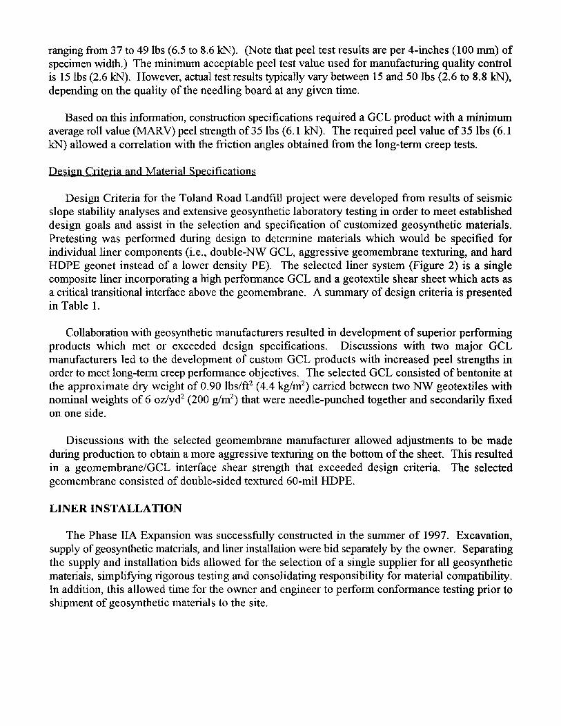
The Toland Road Landfill is located within a high seismic risk area of Southern California in a narrow canyon with steep walls on three sides. Subgrade conditions consist of the moderately indurated Pliocene-Pleistocene age Pica formation, a commonly jointed and fractured marine claystone. Lined side-slopes for the Phase IIA Expansion at the Toland Road Landfill are 1SH: 1V and range in height from 80 to 190 feet (24.4 to 57.9 m) with 25-foot (7.6 m) wide benches every 50 vertical feet (15.2 m). The Phase IIA Expansion is shown in Figure 1. For this project, the State of California required the lined expansion to resist the effects of a Maximum Credible Earthquake (MCE). Therefore, the liner is designed to withstand anticipated peak ground accelerations of up to 0.8g.

The liner system design incorporates a preferential slip plane above the geomembrane in order to provide a high level of confidence that the liner system will maintain its long-term integrity during potential slippage. Meeting this criteria is particularly important at the Toland Road Landfill because the steep side-slopes are prone to relative movement between the waste and the subgrade due to either refuse settlement down-drag forces or seismically induced strong ground motions.
SLOPE STABILITY AND SEISMIC RESPONSE ANALYSIS
The stability and seismic response of the liner system was evaluated for both interim fill conditions and the proposed final landfill configuration. Numerous two-dimensional and pseudo three-dimensional slope stability analyses were performed for the design and further verified using a more sophisticated multi-planar wedge, three-dimensional analysis. The pseudo three-dimensional analysis was performed using the weighted average of several parallel two-dimensional sections. Results of the three-dimensional analysis indicate that three-dimensional effects increase the calculated factor of safety by 13 to 21 percent for the unique geometry analyzed. Based on conventional 3H: IV fill slopes with intermediate benches for the interim fill plan and an acceptable static factor of safety and permanent seismic displacement, a minimum acceptable friction angle of
U
13 degrees was established for the liner system.
DESIGN GOALS AND CRITERIA
durable and and federal
Fundamental design goals for the Toland Road Landfill project include providing a dependable containment liner system for the landfill to meet the intent of state regulations. The following specific issues were addressed to provide a high level of confidence that the liner system will receive acceptable stress levels and maintain its long-term integrity.
Design Goal No. 1 - Provide Protective Cushioning for the Geomembrane
Primary containment for landfill leachate is provided by the geomembrane. The integrity of the geomembrane is affected by the fmess and smoothness of the underlying subgrade. Although the subgrade is very firm due to the nature of the underlying material, it was difficult to provide a smooth surface due to the steepness of bedrock side-slopes. Therefore, it is desirable to provide protective cushioning between the geomembrane and the prepared subgrade. Testing at the Geosynthetics Research Institute (GRI) in the United States (Koemer et al., 1996; Narejo et al., 1996; and Wilson-Fahmy et al., 1996), has shown that GCLs are among the best cushion materials available for geomembranes. In addition, the use of a GCL on the underside of a geomembrane provides additional containment benefits by creating a composite liner system. For these reasons, a GCL was chosen to provide the necessary cushioning.
A design methodology for estimating the degree of cushioning provided by a GCL has been discussed by Koerner et al. (1996), Narejo et al. (1996), and Wilson-Fahmy et al. (1996). The methodology accounts for the normal stress conditions, type of cushioning, angularity of the

subgrade protrusions, isolated stones, arching conditions in the waste, creep, chemical and biological degradation, and a global factor of safety. Taking these factors into account for a GCL cushion, a maximum protrusion size of one inch (25 mm) was specified for subgrade preparation before deployment of the GCL. This is the same value generally recommended by the GCL manufacturers and which was being proposed (during design) in the draft ASTM standard for GCL installation. For ridges and other non-point subgrade irregularities, the value is allowed to be increased to 1.5 inches (38 mm). Construction according to these specifications provides a factor of safety of at least 6 against geomembrane damage. These conclusions resulted in design criteria which were incorporated into the construction specifications.
Design Goal No. 2 - Require Potential Slippage to Occur Above the Geomembrane
The design required careful consideration of the interface strengths between each layer of the liner system. Extensive laboratory testing of numerous geosynthetic materials was conducted to develop a preferential slip plane that has a suitably high post-peak shear strength to achieve slope stability requirements, yet has a lower shear strength than the weakest interface below the geomembrane. There are three potential failure planes below the geomembrane (other than failure in the native soil, which is not anticipated):
9 Interface between GCL and textured geomembrane 2) Internal strength of the GCL 3) Interface between the GCL and the subgrade
Direct shear test parameters and materials were specified by the designers. Geosynthetic testing was performed utilizing a 12-inch by 12-inch (30 cm by 30 cm) shear box in accordance with ASTM Method D5321. Prior to all testing, the GCL was hydrated under zero confining load for 24 hours, followed by consolidation under one-half the specified normal load for an additional 24 hours, with the remainder of the normal load applied just prior to testing. The geonet/geotextile/geomembrane interfaces were sprayed with water immediately prior to testing during unconstrained direct shear tests of the entire liner system. All direct shear tests were conducted at normal stresses of 2,000 psf (96 kPa), 6,000 psf (290 kPa), and 10,000 psf (480 kPa) in order to simulate anticipated normal loads. A shear rate of 0.04 inches/min (1 mm/min) was specified for all direct shear tests.
Based on the authors’ experiences with other projects, the peak interface friction angle between a textured HDPE geomembrane and the non-fixated side of a non-woven (NW) needle-punched (NP) GCL is typically greater than 20 degrees for the range of normal loads anticipated at the Toland Road Landfill. For this project, a friction angle greater than 26 degrees for the textured geomembrane/NW side of a NW-NP GCL interface was measured by the geosynthetic supplier. .
The friction angle for the peak internal shear strength of NW-NP GCLs is approximately 26 degrees for the range of normal loads anticipated at the Toland Road Landfill (see Design Goal No.

3 below). Laboratory interface testing of the GCL against relatively undisturbed samples of subgrade bedrock material indicated an interface friction angle of 18 degrees (both peak and post- peak) when the side of the GCL which receives the secondary fixation is placed against the subgrade. This orientation also resulted in a more favorable (higher) GCL/geomembrane interface friction angle. Based on these results, the peak and post-peak friction angle of the weakest interface above the geomembrane should be less than 18 degrees.
The selected LCRS system included a geonet composite consisting of a 6-oz/yd2 (200 g/m2) NW- NP geotextile heat bonded to the top of an HDPE geonet. A 4-oz/yd2 (135 g/m2) geotextile shear sheet was placed between the bottom of the geonet composite and the top (less aggressively textured side) of the geomembrane to provide a preferential slip plane above the geomembrane. Laboratory testing of the interface between the geotextile shear sheet and the geonet portion of the geonet composite conducted for this project indicated a peak interface friction angle of 14 degrees, and post-peak fiction angle of 13 degrees. This is the minimum post-peak friction angle allowed under conditions of the slope stability analysis, as previously described. This value is also less than the maximum allowable value of 18 degrees. Several unconstrained direct shear tests of the entire liner system were performed as part of conformance testing. With this method of testing, shear failure is free to occur at the weakest interface within the liner system test cross section. Results of shear testing consistently exhibited failure on the preferred interface between the NW geotextile shear sheet and the geonet composite.
Peak stress within the geomembrane will not occur until mobilization of the shear sheet by refuse settlement down-drag forces or seismically induced strong ground motions. The amount of shear stress imposed upon the geomembrane will be limited to that which can be carried by the weakest interface, or the geotextile shear sheet. In theory, the geomembrane at the top of the slope should remain loose and relatively stress-free, even following significant waste-mass displacement along the geotextile shear sheet (assuming waste has already been placed and post-installation downslope creep caused by diurnal expansion and contraction of the geomembrane is not occurring). This concept may present a useful way of monitoring the stress performance of the design after installation.
Design Goal No. 3 - Provide Adequate Long-Term Creep Shear Strength Within the GCL
The NP fibers of the GCL act as structural members and provide internal shear strength. Hence, there is a design concern regarding the long-term creep potential in case the fibers “untangle” or pull out. Long-term shearing behavior of GCLs has been evaluated by Siebken et al. (1996) and Trauger et al. (1996). Both investigators performed creep tests by hydrating the samples prior to loading, followed by the application of constant shear stress for a period of over 7,000 hours. Friction angles reported from these tests ranged from 19 to 27 degrees.
In order to provide GCL materials representative of those used in the long-term creep tests, peel tests (ASTM D 4632) of the same material tested by the investigators were performed with results
ranging from 37 to 49 lbs (6.5 to 8.6 kN). (Note that peel test results are per 4-inches (100 mm) of specimen width.) The minimum acceptable peel test value used for manufacturing quality control is 15 lbs (2.6 kN). However, actual test results typically vary between 15 and 50 lbs (2.6 to 8.8 kN), depending on the quality of the needling board at any given time.
Based on this information, construction specifications required a GCL product with a minimum average roll value (MARV) peel strength of 35 lbs (6.1 kN). The required peel value of 35 lbs (6.1 kN) allowed a correlation with the friction angles obtained from the long-term creep tests.
Design Criteria and Material Specifications
Design Criteria for the Toland Road Landfill project were developed from results of seismic slope stability analyses and extensive geosynthetic laboratory testing in order to meet established design goals and assist in the selection and specification of customized geosynthetic materials. Pretesting was performed during design to determine materials which would be specified for individual liner components (i.e., double-NW GCL, aggressive geomembrane texturing, and hard HDPE geonet instead of a lower density PE). The selected liner system (Figure 2) is a single composite liner incorporating a high performance GCL and a geotextile shear sheet which acts as a critical transitional interface above the geomembrane. A summary of design criteria is presented in Table 1.
Collaboration with geosynthetic manufacturers resulted in development of superior performing products which met or exceeded design specifications. Discussions with two major GCL manufacturers led to the development of custom GCL products with increased peel strengths in order to meet long-term creep performance objectives. The selected GCL consisted of bentonite at the approximate dry weight of 0.90 lbs/ft2 (4.4 kg/ m 2, carried between two NW geotextiles with nominal weights of 6 oz/yd2 (200 g/m2) that were needle-punched together and secondarily fixed on one side.
Discussions with the selected geomembrane manufacturer allowed adjustments to be made during production to obtain a more aggressive texturing on the bottom of the sheet. This resulted in a geomembrane/GCL interface shear strength that exceeded design criteria. The selected geomembrane consisted of double-sided textured 60-mil HDPE.
LINER INSTALLATION
The Phase IIA Expansion was successfully constructed in the summer of 1997. Excavation, supply of geosynthetic materials, and liner installation were bid separately by the owner. Separating the supply and installation bids allowed for the selection of a single supplier for all geosynthetic materials, simplifying rigorous testing and consolidating responsibility for material compatibility. In addition, this allowed time for the owner and engineer to perform conformance testing prior to shipment of geosynthetic materials to the site.
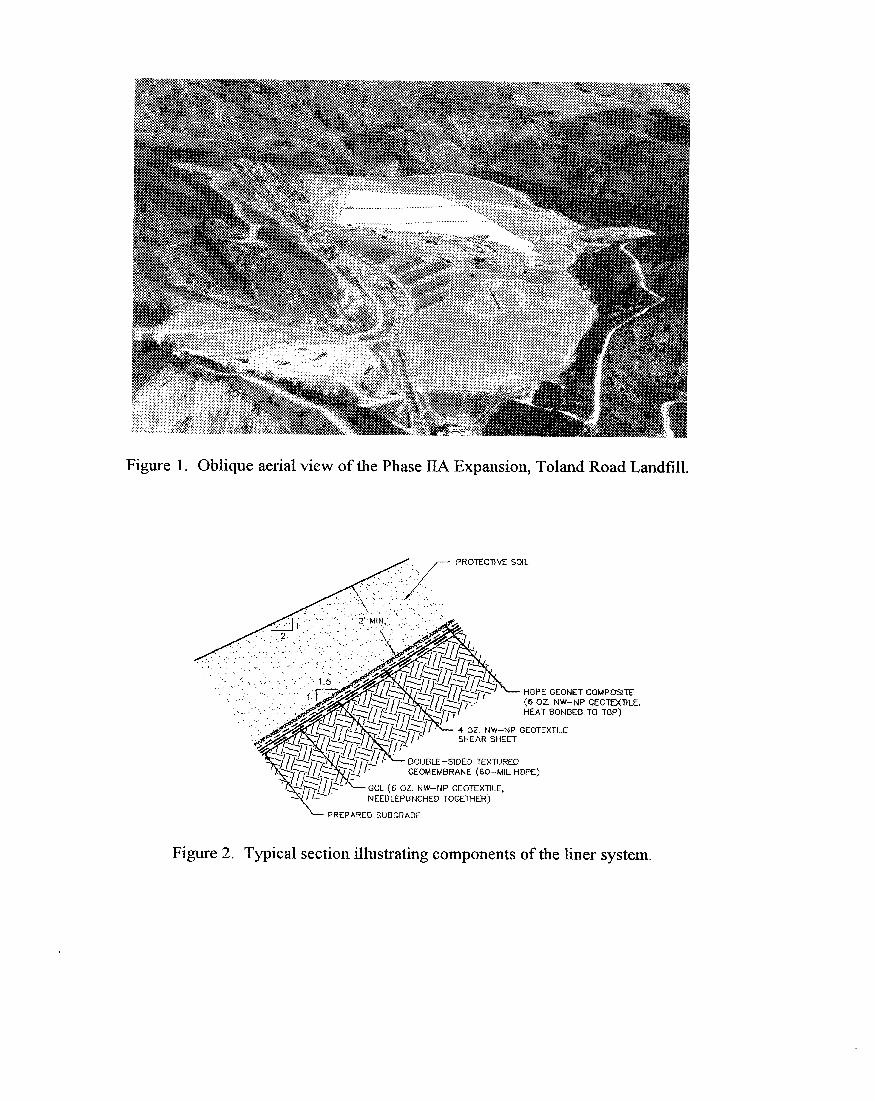
Figure 1. Oblique aerial view of the Phase IIA Expansion, Toland Road Landfill.
HOPE GEONEl (6 OZ. NW-NI HEAT BONDEC
*NP GEOTEXTILE
GEOMEMBRANE (60~ML HDPE)
GCL (6 OZ. NW-NP GEOTEXTILE, NEEDLEPUNCHED TOGETHER)
I, PREPARED SUBGRADE
3
CQMPOSITE GEOTEXTILE, TO TOP)
Figure 2. Typical section illustrating components of the liner system.

Table 1. Design Criteria
Peak Shear Strength Shear Strength Requirements Interface Requirements after a minimum of 3 inches of
displacement GCL - internal 25 degrees min. (provides a N/A
correlation with long-term creep tests)
GCL /subgrade 18 degrees min.; Subgrade 18 degrees min. (post-peak value interface protrusions < 1 in., irregularities required since some sliding of
< 1.5 in. this interface may occur during construction)
GCL/textured 24 degrees min. (exceeds actual N/A (post-peak value not geomembrane requirement of 18 degrees to allow required since design is based on interface for installation damage and peak strength being maintained,
product variability) while accounting for some potential installation damage)
geotextile shear 22 degrees min. (exceeds actual N/A (post-peak value not sheet/textured requirement of 18 degrees to allow required since design is based on geomembrane for installation damage and peak strength being maintained, interface product variability) while accounting for some
potential installation damage) geotextile shear 16 degrees max., 13 degrees min. 16 degrees max., 13 degrees min. sheet/geonet (max. value set to meet Design (post-peak values required since composite interface Goal No. 2; min. value set to meet this is the interface that will slip
slope stability requirements) during waste settlement or seismic events)
Because it was critical for each element of the liner system to perform as designed, the selected supplier was required to demonstrate that the various interface shear strength specifications could be met by submitting interface shear test results of representative materials prior to contract execution. Bidding the supply portion of the contract separately allowed the owner and engineer to coordinate directly with the geosynthetic supplier and eliminated the possibility of the general contractor or installer from bidding material which did not meet the performance requirements.
The highly jointed and fractured nature of native materials made it difficult for the contractor to provide subgrade conditions which met the construction specifications. Final slope preparation involved manual raking by laborers and smoothing using a backhoe and bar attachment. On portions of the slope, landslide and unconsolidated material required excavation and replacement with compacted fill keyed into the subgrade.

During installation of the GCL, the subgrade surface was continuously inspected to verify the removal of materials that could damage or adversely affect the integrity of the liner system. GCL panels were deployed from the top of slopes and unrolled down the entire length of the slope, across intermediate benches, beneath the LCRS header along the toe, and anchored at the limit of the adjacent unlined portion of the landfill.
Geomembrane panels were deployed in a continuous sheet from the uppermost bench to the bottom of the slope with the more aggressively textured side facing down, utilizing a thin HDPE slip sheet to avoid snagging and weakening the NW fibers of the GCL. Once a geomembrane panel was positioned, the slip sheet was removed. Only as much GCL that could be covered in the same day by the geomembrane was deployed. The need for cross-slope seams and anchor trenches on intermediate benches was eliminated by specifying 520 foot (158 m) long roll lengths. Initially, this resulted in bridging of geomembrane panels along the back of benches which was remedied by increasing the number of sandbags placed on the geomembrane immediately following liner placement, most notably in the afternoon during peak thermal elongation. Areas which had already bridged were cut out and replaced with an extrusion-welded cap strip. Geomembrane installation is shown in Figure 3.
As in the case of the geomembrane, the geotextile shear sheet was installed utilizing a slip sheet to allow positioning of panels and to prevent dragging of the shear sheet over the geomembrane which could damage the NW fibers (Figure 4). The preferential slip plane was completed with installation of the geonet composite, with the HDPE drainage net side facing down against the geotextile shear sheet. As with the deployment of other liner system components, the geonet composite was unrolled from the uppermost bench, but did not utilize a slip sheet and was slid down the slope directly over the geotextile shear sheet.
Remaining components of the LCRS, including leachate collection pipe, granular leachate collection layer, and geotextile filter, were subsequently installed along the back of benches and at the toe of the slope following construction quality assurance (CQA) approval of the underlying composite liner. A lo-foot (3 m) high temporary operational and leachate containment berm was constructed at the toe of the expansion between lined slopes and existing unlined waste fill areas. A prefabricated HDPE boot provided temporary penetration for the LCRS header until construction of the adjacent expansion phase.
A temporary plastic cover manufactured from laminated scrim-reinforced polyethylene sheeting and anchored with roped sandbags placed on lo-foot centers was installed over portions of the liner which would not immediately receive waste. The purpose of the temporary plastic cover was to protect the geonet composite from ultraviolet degradation and prevent stormwater runoff from entering the LCRS. The cover is peeled back as operations proceed and anchored within the operations layer to create a lined interim V-ditch.

Figure 3 (left). Geomembrane installation over GCL showing 1SH: 1V slopes and intermediate benches.
Figure 4 (below). Geotextile shear sheet installation over geomembrane on 1.5H: 1V slope. Photo taken from intermediate bench at the top of slope.

CONCLUSIONS
This case study has presented the innovative specification and use of customized geosynthetic materials to meet slope stability requirements and achieve design goals for a composite liner system installed on steep side-slopes in a high seismic risk area. Working closely with geosynthetic manufacturers, customized products with enhanced properties can be produced to suit the needs of the designer for projects which require superior performing products. The authors recommend visiting the geosynthetic manufacturing plant during production to perform quality assurance inspection, collect conformance test samples, and personally observe production of actual materials to be used in construction.
A preferential slip plane may be incorporated into a composite liner system in order to restrict sliding to a specific interface located above the geomembrane. Extensive laboratory interface testing during the design phase of numerous geosynthetic materials under various conditions is necessary to identify the appropriate combination of materials which will satisfy both slope stability and containment goals. In this case study, a slip plane design utilizing a NW geotextile shear sheet is based on a narrow shear strength envelope determined by the minimum friction angle required for slope stability and me lowest interface friction angle beneath the geomembrane. The weight of the shear sheet was not specified, allowing the supplier a degree of flexibility in meeting the performance specifications.
The stability of the design needs to be evaluated to determine not only how the proposed liner system will perform during interim fill conditions, but how it will integrate with future expansions and impact the long-term performance of the proposed final configuration. In this case study, a pseudo three-dimensional analysis was performed using the weighted average of several parallel two-dimensional sections and further verified using a more rigorous three-dimensional analysis. Results of the three-dimensional analysis indicate that the more simplified pseudo three-dimensional analysis is conservative and has merit in the analysis of landfill liner systems.
Because a composite liner has to act as a single system, careful consideration must be given to development of construction specifications. The authors believe that requiring suppliers of geosynthetic materials to provide performance testing as a condition of contract should be considered. In addition, the contractor needs to demonstrate an ability to comply with specification requirements and can be required to conduct performance testing.
Bidding the supply of geosynthetic materials separate from the installation offered numerous advantages. For this case study, the selected supplier was able to supply all geosynthetic materials, allowing the owner and engineer to coordinate directly with the manufacturer and eliminating the possibility of general contractors incorrectly evaluating results of specialized and complicated testing which may have resulted in the disqualification of several otherwise responsive bidders.

ACKNOWLEDGMENTS
The authors wish to thank Rob Swan of GeoSyntec Consultants for providing geosynthetic testing, Jonathan Bray and Timothy Stark for separate reviews of the seismic stability, CETCO and National Seal Company for providing GCL materials used in preliminary testing, Greg Sharrun of Columbia Geosystems Ltd. for providing geomembrane materials used in testing, and the cooperation of John Conaway and the Ventura Regional Sanitation District for allowing the use of their case history in this paper.
REFERENCES
Koerner, R.M., Wilson-Fahmy, R.F., and Narejo, D., and 1996, Puncture Protection of Geomembranes Part III: Examples, Geosynthetics International, Vol. 3, No. 5, 1996, pp. 655-675.
Narejo, D., and Koerner, R.M., and Wilson-Fahmy, R.F., 1996, Puncture Protection of Geomembranes Part I: Theory, Geosynthetics International, Vol. 3, No. 5, 1996, pp. 605-628.
Siebken, J.R., Swan, R.H., and Yuan, Z., 1996, Short-Term and Creep Shear Characteristics of a Needlepunched Thermally Locked Geosynthetic Clay Liner, in Testing and Acceptance Criteria for Geosynthetic Clay Liners, ASTM STP 1308, Larry Well (ed.), American Society for Testing and Materials, Philadelphia.
Trauger, R.J., Swan, Jr., R.H., and Yuan, Z., 1996, Long-Term Shear Strength Behavior of a Needlepunched Geosynthetic Clay Liner, h Testing and Acceptance Criteria for Geosynthetic Clay Liners, ASTM STP 1308, Larry W. Well, (ed.), American Society for Testing and Materials, Philadelphia.
Wilson-Fahmy, R.F., Narejo, D., and Koerner, R.M., 1996, Puncture Protection of Geomembranes Part II: Experimental, Geosynthetics International, Vol. 3, No. 5, 1996, pp. 629-653.