chapter 3 power generation and control systems · chapter 3 power generation and control systems...
TRANSCRIPT

CHAPTER 3
POWER GENERATION AND CONTROL SYSTEMS
Aviation Electricians Mates (AEs) operate and maintain various modern naval aircraft systems As an AE you must know the electric power systems of these aircraft The electric power requirements and the electric system components of aircraft vary widely according to the size and application of the aircraft You must understand the component parts of the electrical systems and the power distribution systems of modern naval aircraft Alternating Current (ac) generators supply the electrical energy for operating aircraft avionics equipment A generator is a machine that converts mechanical energy into electrical energy by electromagnetic induction Navy Electricity and Electronics Training Series (NEETS) Module 5 Introduction to Generators and Motors NAVEDTRA 14177 contains a detailed discussion on generator theory You should study this module and refer to it during your study of this chapter
LEARNING OBJECTIVES
When you have completed this chapter you will be able to do the following 1 Identify various electrical power sources used on aircraft and recognize their
functions construction and operating characteristics 2 Explain the reasons for and means of protecting electrical circuits through use of
voltage and frequency control circuits and associated circuits
AIRCRAFT ELECTRICAL POWER SOURCES
AC Generators
Modern ac power systems provide for better aircraft equipment design and use Older electronic equipment powered by direct current had an inverter for ac power and a dynamotor for supplying higher voltage Direct Current (dc) power These components are very heavy compared to their relative power outputs They are not reliable and they increase maintenance The same ac-powered equipment obtains various ac voltages and dc power by using simple transformers and transformer-rectifiers These components are lightweight simple and reliable devices Modern naval aircraft use the three phase 120-208-volt 400-hertz ac power system in order to meet increasing aircraft power requirements The number of magnetic poles and rotor Revolutions per Minute (RPM) determines the voltage frequency of the generator Constant frequency requires constant rotor RPM when the number of poles are a fixed quantity The ac generator rotating field has 12 poles with adjacent poles being of opposite polarity Each pair of poles produces one cycle per revolution therefore each revolution produces six cycles The output frequency of the generator varies in direct proportion to the engine drive speed A generator operating at 6000 RPM is operating at 100 revolutions per second or at 600 hertz NEETS Module 5 contains a detailed discussion of frequency
3-1
Figure 3-1 mdash Three-phase ac generator output
The 120-208-volt 400-hertz three-phase ac power system has many advantages over the 28-volt dc system It requires less current than the 28-volt dc system because of higher voltage and a ground neutral system The current required is a fraction of that required for the same power in a 28-volt dc system This permits the use of smaller aircraft wiring saving weight The ac generator and many of the systems control and protection components are lighter Twelve kilowatts is the practical limit to the size of an aircraft dc generator Aircraft now have ac generators with ratings up to 90 kilovolt ampere (kVa)
Types of AC Generators
Aircraft ac generators range in size from the tachometer instrument generator up to the 90000 volt-ampere generators Regardless of weight shape or rating practically all of these generators have the following common characteristics
The stator (stationary armature winding) provides the ac output
The ac generator field (rotor) is a rotating magnetic field with fixed polarity
Regulating the RPM of the rotating magnetic field controls the voltage frequency
Controlling the strength of the magnetic field is the method of voltage regulation Present military specifications require that the basic aircraft ac power system produces voltage with a value of 120 and 208 volts A three-phase generator is actually three separate power sources enclosed in one housing (Figure 3-1 view A) External connections form a wye (Figure 3-1 view B) to produce the required 120-208-volt output Each output winding produces 120 volts as measured from n to a b or c (phase voltage) The voltage is 173 times the single-phase voltage when measuring two separate phase voltages together (line voltage)
3-2
Figure 3-2 mdash Brush-type three-phase ac generator
The line voltage found in a three-phase wyeshyconnected system is the vector sum of the voltages generated by two separate phase windings Voltages reach their peak amplitudes at different times because a 120-degree phase difference exists between them Due to this phase difference they must be added vectorially and not directly In the four-wire grounded-neutral wye-connected system the neutral wire attaches to the frame of the aircraft (ground) The three-phase wires run to buses which supply power to various loads The connections for loads requiring 120 volts are between one of the buses and the aircraft frame The load connections requiring 208 volts are between two of the buses (phases) BRUSH TYPE ndash Figure 3-2 shows a brush type ac generator It consists of an ac generator and a smaller dc exciter generator as one unit The output of the generator supplies ac to the load The only purpose for the dc exciter generator is to supply the direct current required to maintain the ac generator field Figure 3-2 view B is a simplified schematic of the generator
Refer to Figure 3-2 as you read this section The exciter is a dc shunt-wound self-excited generator The exciter field (2) creates an area of intense magnetic flux between its poles Voltage is induced in the exciter armature windings when the exciter armature (3) rotates in the exciter-field flux The output from the exciter commutator (4) flows through brushes and slip rings (5) to the generator field Having already been converted
3-3
Figure 3-3 mdash Disassembled brushless ac generator
by the exciter commutator the dc current always flows in one direction through the generator field (6) Thus a fixed-polarity magnetic field is maintained in the generator field windings When the field winding rotates its magnetic flux passes through and across the generator armature windings (7) The ac in the ac generator armature windings flows through fixed terminals to the ac load The stationary member of the generator consists of the ac armature and the dc exciter field Both ac and exciter terminal boards are easily accessible All brush rigging is on the generator and has a brush cover The slotted-hole mounting provides for ease in attaching to the engine pad The capacitors connected between the exciter armature terminals and ground suppresses radio noise BRUSHLESS TYPE ndash Most naval aircraft are using brushless generators for voltage generation The advantage of a brushless generator over a brush type is its increased reliability and the greater operating time between overhaul Figure 3-3 is an expanded view of the main assembly of a brushless generator It shows those items that you will find important The brushless generator shown in Figure 3-3 is a salient eight-pole 6000 RPM ac generator It has a 12-pole ac exciter and a three-phase halfshywave diode rectifier rotating with the exciter armature and main generator field assembly The exciter rotor is a hollow frame assembly with the main ac field mounted on the inside and connected to a common drive shaft A single-phase Permanent Magnet Generator (PMG) furnishes control voltage and power for the voltage regulator Three half-wave rectifiers are on the exciter rotor and connected to the exciter armature windings A generator shaft shear section prevents possible damage to the engine or drive unit if the generator seizes A fan at the drive end of the generator provides cooling airflow for the rotor and stator windings and the drive bearings
3-4
Figure 3-4 mdash Sectional schematic of a
brushless ac generator
Some aircraft have oil-cooled generators The oil enters the generator through an inlet port and leaves through an exit port in the mounting flange of the generator As the oil passes through the generator it absorbs the heat from the rotor and stator At the same time it cools the rotating seals and lubricates and cools the bearings Aircraft engine oil cools the generator and is used for the constant speed drive operation As the generator shaft rotates (Figure 3-4) the PMG supplies single-phase ac voltage to the voltage regulator and other protective circuits PMG power is rectified and supplied to the exciter field The electromagnetic field built by the excitation current flowing in the exciter induces current flow in the rotating three-phase exciter rotor This current is half-wave rectified by rotating rectifiers The resultant dc goes to the rotating field winding of the ac generator The rotating electromagnetic field induces ac voltage in the three-phase wye-connected output winding of the generator stator Varying the strength of exciter stationary field accomplishes voltage regulation Brushes within the generator arent required when an integral ac exciter is used The absence of brushes minimizes radio noise in other avionics equipment Two three-phase differential transformers provide protection against shorts in the feeder lines between the generator and the bus (called feeder fault) One transformer is on the generator (Figure 3-4) Its coils sense the current flow through each of the legs that connect the ground side of the generator stator to ground The other transformer is at the main bus and senses current flow through the three feeder lines A short in the feeder line would cause the transformers sensing a difference in current to trip the generator off line A generator mechanical failure warning device is incorporated in the generator It consists of a soft copper strip embedded in and insulated from the generator stator assembly A bearing beginning to fail allows the rotor to rub against the copper strip completing a warning light circuit to ground
3-5
Prime Movers
A prime mover is a device such as an aircraft engine that provides the driving force for a generator Early attempts to control the rotor speed of ac generators using variable-pitch propellers or slipping clutches were unsuccessful and ac generator power was of variable frequency If a constant frequency power for the equipment were available savings in weight and improved performance would be possible From the weight and performance standpoint as power requirements grew it became necessary to furnish ac power at a constant frequency The constant frequency was found in a hydromechanical Constant Speed Drive unit (CSD) Other constant speed units are air or gas turbines and the constant RPM turboprop engine The air turbine gets its air supply by using bleed air from the jet engine compressor or from a separate compressor The hydromechanical CSD unit converts variable engine speed to a constant speed output It holds the frequency steady to within a few hertz of the desired 400 hertz Load and fault transients limits are within a 380- to 420-hertz range Air or gas-turbine drives are somewhat smoother in operation and hold steady-state frequencies to within plusmn 10 hertz The constant RPM characteristic of the turboprop engine gives good frequency stability to the ac generator output The propeller mechanical governor will hold the generator frequency to 400 plusmn 4 hertz
Inverters
Inverters are an emergency source of ac power when normal ac power fails The backup system of the FA-18 aircraft is an example of this type The standby attitude indicator receives power from the right 115-volt ac bus If the aircrafts generators fail to supply power to this bus the standby attitude indicator receives power from an inverter Because of a wide variety of inverters in use on aircraft only one is discussed in this Rate Training Manual Inverters consist of a speed-governed dc motor an armature and brush assembly and a permanent magnet inductor-type ac generator in one unit The armature and the permanent magnet rotor mount on a common shaft The standard inverter is a 120-volt three-phase four-wire 400-hertz ac system The four-wire system is better than the three-wire system It allows a greater choice of single-phase circuits improves phase load balance decreases vulnerability to power failure and gives better frequency and voltage control The dc armature and the ac generating field windings are on the same rotor shaft in most inverters The dc motor field and generator output (armature) windings are on the stator A control box on the inverter contains the necessary devices to control the inverters operation These devices consist of the operating relays voltage regulator and rectifier filtering units and smaller circuit components The dc motor of most aircraft inverters is essentially a shunt-wound motor High starting currents and a low rate of acceleration (because of low torque at starting) are characteristic of shuntshy wound inverters The larger inverters have a series-starting winding to help avoid the effects of these undesirable characteristics When the inverter reaches rated speed relays disconnect the series-starting winding and connect the dc input to the dc motor armature and the shunt winding Then the inverter operates as a shunt-wound motor having desirable constant-speed characteristics Others use small compensating and commutating pole windings in series with the motor armature These windings have no effect on the shunt-motor action
3-6
Figure 3-5 mdash Typical aircraft inverter
The dc motor converts electrical energy into mechanical energy to drive the generator The dc load current drawn by the motor depends on the ac load on the generator A speed governor or pulsating dc current through the field windings controls motor speed A solid-state ON-OFF switching circuit provides the pulsating direct current The speed of a dc motor is inversely proportional to the strength of the field Therefore as the motor speeds up more current flows in the shunt windings reducing the speed Less current flows in the shunt-field windings and the motor speeds up when the motor speed falls below its normal value The generator ac voltage is proportional to the speed of the rotor and the strength of the generator rotor field flux The controlled frequency of the ac output is usually 400Hz This frequency is a function of the number of poles in the generator field and the speed of the motor The number of sets of generator stator windings determines the number of independent voltages or phases in the output Some inverters supply both three-phase and single-phase outputs Figure 3-5 shows a typical inverter
The rating of aircraft inverters varies depending on the equipment that it supplies For example an aircraft may carry a number of inverters One may supply 120-volt threeshy phase ac to an essential bus during emergencies Another supplies 120-volt single-phase ac power while another furnishes 120-volt three-phase power to a specified bus or equipment Figure 3-6 shows a cutaway view of an inverter Controlling the dc excitation current in the generators rotating field maintains the inverter output voltage at a constant value Demand variations on the inverter output determine the strength of the dc rotating field
3-7
Figure 3-6 mdash Cutaway view of an E1616-2 inverter
Inverters operate on the same electrical principles as dc motors and ac generators NEETS Module 5 discusses these principles For more information on the theory of voltage generation and regulation you should refer to the NEETS Module 2 Introduction to Alternating Current and Transformers NAVEDTRA 14174 and Module 5 For detailed information about a particular inverter refer to the manuals covering that inverter
Transformers
A transformer by itself is not a true electrical power source A-true electrical power source can produce electrical energy from another type of energy such as chemical or mechanical Transformers take electrical energy in the form of ac voltage and convert it to a different usable ac voltage If you feel you need to study transformer construction and theory you should refer to the NEETS Module 2 before continuing this chapter
Transformer-Rectifiers
Currently ac-powered equipment is more efficient than larger heavier dc-powered equipment So ac generators now power naval aircraft but dc power is needed for lighting and for controlling ac-powered equipment The most common device now used to provide the necessary dc voltage is the Transformer Rectifier (TR) TRs have no moving parts other than a cooling fan They provide high reliability and ruggedness unmatched by most other avionics equipment A separate voltage regulator
3-8
Figure 3-7 mdash Schematic diagram of a typical transformer rectifier
is not necessary so long as the ac input voltage maintains reasonable limits The dc current capability is high and is largely dependent on the cooling available Figure 3-7 shows an electrical schematic of a typical transformer-rectifier You should refer to it as you read this section It requires a 120-208-volt three-phase four-wire input at 400 hertz It has an output capability of 200 amperes at 255 to 295 volts
The input ac voltage enters through pins B F and I and enters a Radio Frequency (RF) filter The filter reduces noise interference to other avionics equipment in the aircraft Power then connects with the wye-connected primary of a step-down power transformer The ac output of the wye delta-connected secondaries is rectified by diodes CR1 through CR12 The output goes through interphase transformer T2 and a filter network consisting of L2 C4 and C5 to the load Interphase transformer T2 has an adjustable center tap to balance the two delta transformers for equal current output The filter network reduces the 4800-hertz ripple voltage to nearly straight-line dc voltage Fan motor B1 is connected in parallel with the power transformer primary This fan motor is essential to proper operation and provides the only moving parts of the TR Thermostat (S1) provides detection of excessively high temperatures and in conjunction with external circuits turns on an overheat warning light and automatically disconnects the input
3-9
Figure 3-8 mdash A 21 ratio autotransformer
Autotransformers
The autotransformer is like an ordinary transformer except that it has one winding that is common to both primary and secondary Within the limits of its application it offers savings in both size and cost over conventional units These savings are greatest when the turn ratio is less than 2 to 1 (either step-up or step-down) Savings diminish to insignificance when the turn ratio increases beyond 8 to 10 There is no isolation between primary and secondary positions of the circuit a feature that is sometimes objectionable Figure 3-8 shows a 21 step-down autotransformer circuit Refer to this figure as you read this section The tap at point B divides the winding into two equal parts With a load of 5 ohms connected as shown compute the load current using the formula
I =
or
= 10 amperes The power in the load equals EI (50 x 10) or 500 watts Just
like a regular transformer this power comes from the primary by the magnetic field Disregarding losses the primary must take 500 watts from the line Therefore the
primary current would be
(
) or 5 amperes Only the difference between these
two currents 5 amperes flows in the common portion C to B (shown by the arrow) The current in both sections of the winding is the same when the turn ratio is 21 This saves the cost and weight of an entire winding
3-10
Figure 3-9 mdash A 1331 ratio autotransformer
The autotransformer in Figure 3-9 has a turn ratio of 1331 It connects to a load that draws 20 amperes This represents a secondary power of EI = (90 x 20) or 1800 watts The primary current neglecting losses equals
(
) or 15 amperes The
current in the winding from B to C common to both circuits is the difference between the primary and secondary line currents or 5 amperes The saving here is obvious A conventional transformer with the same characteristics requires a 120-volt 15-ampere primary and a separate 90-volt 20-ampere secondary Here the requirement is a 30-volt 15-ampere winding in series with a 90-volt 5-ampere winding Thus a 045-kVA autoshytransformer supplies the 18-kVA load There are many interesting uses for autotransformers An autotransformer with a continuous variable tap is sold under the name VARIAC It is used for many purposes where a continuous control from zero to full (or even above) line voltage is necessary In this case the core is toroidal (ring shaped) The winding is usually in the form of a single layer covering almost the entire surface A control shaft carries an arm and a brush that makes contact with each turn of the winding as the shaft rotates The setting of the shaft determines the turn ratio One end of the winding goes to both line and load and the other end goes to the line The brush connects to the other side of the load To obtain voltages higher than line voltage the primary connects to a tap about 10 percent down from the end of the winding (Voltages higher than line voltage compensate for abnormally low line voltage) This provides secondary control from zero to full line voltage even though the actual line voltage is as much as 10 percent below normal
Instrument Transformers
Usually meters are not connected directly to high-voltage and high-current ac circuits Instrument transformers connect meters to these circuits These transformers are of two general typesmdash the current and the potential They permit the use of standard low-voltage meters for all high-voltage or high-current ac circuits They also protect the operating personnel from the highshyvoltage circuits For more information on instrument transformers you should study NEETS Module 2 It covers transformers in detail
3-11
Figure 3-10 mdash Typical electronic power
supply
Electronic Power Supplies
In high performance aircraft avionics systems help the pilot communicate navigate or fire missiles Other systems such as radar and autopilot Automatic Flight Control System (AFCS) ease the pilots workload Each of these systems requires precision voltage inputs for proper operation For example an inertial navigation system may require the voltages shown in Table 3-1 The voltages required by an AFCS in the same aircraft are shown in Table 3-2 Obviously one simple electrical power source wont provide all the needed power for 20 or 30 avionics systems Normally each avionics system has its own power supply Figure 3-10 shows the power supply for a typical autopilot system The power supply requirements (Table 3-2) are for a 120-208-volt three-phase four-wire 400-hertz electrical power input
Table 3-1 mdash Electrical Requirements for an Inertial Navigation System
DC VOLTAGES AC VOLTAGES
+45 V transistor bias 26 V 400 hertz
-45 V transistor bias 140 V 400 hertz three phase
+28 V unfiltered and unregulated 90 V 375 hertz three phase
+28 V transistor bias 126 V 400 hertz
+28 V unregulated relay excitation 63 V 400 hertz
+20 V transistor bias
+10 V reference
-10 V reference
3-12
Figure 3-11 mdash Developing ac voltages for the autopilot
Table 3-2 mdash Electrical Requirements for a Typical Transistorized Autopilot System
Phase A Phase B Phase C DC
120 VAC 120 VAC 120 VAC 28 V filtered
45 VAC 26 VAC 15 VAC 28 V unfiltered
26 VAC 15 VAC 10 VAC
19 VAC
15 VAC
7 VAC
Look at the schematic shown in Figure 3-11 Autotransformers T4 T5 and T6 produce the majority of the output voltages The autotransformers have taps from each transformer winding at the proper position to produce the required voltage No further voltage regulation is necessary under fairly constant load conditions
3-13
Figure 3-12 mdash Full-wave rectifier and filter network
Figure 3-13 mdash Precision dc voltage
developer
Full-wave rectifiers (Figure 3-12) produce dc voltages Each pair of rectifiers (either CR7 and CR10 or CR8 and CR9) conducts during alternate half cycles of the ac input from the secondary of step-down transformer T7 The unfiltered dc provides power to operate lights and relays for internal operation of the system and feeds a filter network Also filtered dc supplies transistor bias to the electronic amplifiers in the autopilot system
The circuit shown in Figure 3-13 develops precision dc voltages Diode CR1 is a Zener diode that develops a constant dc voltage at the input of amplifier A1 regardless of input voltage fluctuations CR1 will conduct harder and the excess voltage drops across R1 if the dc input voltage at the top of R1 increases If the voltage decreases CR1 conducts less and less voltage drops across R1 This maintains the voltage at the anode of CR1 at a constant precision potential If no current flows through R2 the same potential present at the input of amplifier A1 and on the anode of CR1 is the same Feedback voltage through resistors R3 and R4 control the gain of amplifier A1 The potential of the output voltage and the anode of CR1 are the same when the combined resistance values of R3 and R4 are the same as the resistance of R2 Variable resistor R4 provides fine tuning of the output voltage to the desired level Isolation amplifier A1 prevents changes in the load current from being felt at the Zener diode
3-14
Figure 3-14 mdash Typical aircraft storage battery with quick
disconnect
There are many methods of providing both dc and ac precision voltages NEETS Module 6 Introduction to Electronic Emission Tubes and Power Supplies NAVEDTRA 14178 discusses several of these methods
EMERGENCY POWER SOURCES
Naval aircraft have backup (emergency) electrical power if primary sources of electrical power fail The various ways of supplying this emergency power are aircraft storage batteries hydraulic motor-driven generators and ram airshy driven turbine generators The following paragraphs discuss each of these systems
Batteries
Aircraft storage batteries provide an emergency source of electrical power for operating electrical systems of an aircraft The ac generator and transformer-rectifier combination supply electrical energy and maintain the battery in a charged state during normal aircraft operation The battery supplies power to the aircraft only when the generating systems are unable to supply power Figure 3-14 shows an aircraft storage battery with a quick disconnect The battery is the emergency power source for the aircraft As such you should maintain the battery in perfect condition at all times Never use the battery for starting engines or servicing equipment if another power source is available Doing so shortens the batteryrsquos life The service life of the aircraft battery depends upon the frequency and quality of care it receives The most common aircraft batteries used today are lead-acid nickel-cadmium and silvershy zinc batteries For detailed information on batteries refer to NEETS Module 1 It covers the basic principles of batteries Another reference on batteries is Naval Aircraft Storage Batteries NAVAIR 17-15BAD-1 Most wet-cell batteries emit some type of gas when being charged or discharged This is especially true of lead-acid batteries and to a lesser degree the nickel-cadmium and silver-zinc batteries A vent in the filler plug allows each cell to vent gas and moisture into the void of the battery Allowing the moisture to stand in the battery void could cause shorting of the cells and corrosion so openings at each end of the battery provide ventilation of the void area In a vent system (Figure 3-15) the void above the cells and beneath the sealed cover is subject to differential pressure through the vent nozzles The higher of the two vent nozzles connects to a rising vent tube exposed to positive pressure on the aircraft surface This provides definite pressure on the battery while in flight It acts as a chimney for light hydrogen gas when the aircraft is at rest The lower of the two vent nozzles connects a tube exposed to negative pressure on the aircraft surface This tube allows battery acid to escape without injury to the aircraft
3-15
Figure 3-15 mdash Battery vent system
In the battery drain sump the negative pressure tube from the battery connects to a jar sump and extends 1-inch into the jar The exhaust tube from the sump jar is cut at a 30-degree angle It extends into the sump jar for one-third its depth The tube then runs to the aircraft surface Normally the sump jar contains a felt pad The lead-acid battery is moistened with a concentrated solution of sodium bicarbonate for neutralizing gases and excess battery solution You should refer to the aircrafts MIM for specific directions concerning the maintenance of the vent-sump system for your aircraft
ACDC Hydraulic Motor-Driven Generators
The acdc hydraulic motor-driven generators are emergency power sources They consist of the following components a hydraulically-driven acdc generator a motor-generator control unit and a control solenoid The motor-generator provides 115-200-volt ac and 28-volt dc power to essential electrical circuits if normal power fails The kVA rating of this emergency generator is much lower than the primary generator(s) Hence the emergency generator powers a limited number of circuits ACDC GENERATOR ndash As the rotor turns (hydraulic motor running) the permanent magnet induces power into the PMG This power energizes the control and regulation circuits and the four essential power transfer relays Regulated and rectified PMG output power goes to a stationary control field within the motorshygenerator The motion of the rotor assembly induces PMG power into the windings of the exciter alternator This power is rectified and in turn induced into the output ac winding and the dc winding The motor-generator control unit monitors ac output This unit adjusts the regulation to maintain the ac output at 115 volts per phase plusmn 150 when operating under full hydraulic system pressure The dc output from the stationary rectifier goes to the dc transfer relay contacts for distribution to the essential dc buses The hydraulic motor converts 3000 PSI of hydraulic pressure to constant-speed rotation maintaining generator output frequency at 400 Hz (Figure 3-16) The motor-generator is cooled by hydraulic fluid from the same source that drives the hydraulic motor
3-16
Figure 3-16 mdash Motor-generator MOTOR-GENERATOR CONTROL ndash The motor-generator control provides voltage regulation for and detection of motor-generator output When the motor-generator is operating PMG power flows to the rectifier where the three-phase ac is rectified to a dc signal The dc signal is for control panel and relay control power Then the signal flows to the voltage regulator section of the motorshygenerator control unit The voltage regulator supplies field excitation to the motor-generator and monitors the output voltage Monitoring protective circuits in the motor-generator control prevent out-of-tolerance power from being connected to the essential bus system MOTOR-GENERATOR SOLENOID CONTROL VALVE ndash The motor-generator solenoid control valve (Figure 3-17) controls the operation of the emergency electrical power system The valve drives electrically to the closed position when primary electrical power is available The valve de-energizes and opens routing hydraulic pressure to the hydraulic motor driving the generator when primary electrical power fails The entire operation is completely automatic upon primary electrical power failure
3-17
Figure 3-17 mdash Motor-generator solenoid control valve
Ram Air Turbine Generator
Some naval aircraft have a Ram Air Turbine (RAT) emergency generator hence the name emergency generator provides emergency electrical power in the event of main electrical power failure Different types of emergency power generating systems are available and their installation depends upon aircraft typemodelseries In the EA-6B installation when the RAT is deployed it extends into the airstream This occurs when the pilot pulls upward on the ELEC-AIR TURBINE T-handle assembly a lever which mechanically links the turbine manual selector valve ports hydraulic fluid to the extend port to hydraulically cause the RAT to protrude in the airstream The ram air of flight (caused by the aircraft moving through the air) provides the turning power for the turbine blades This in turn rotates the generators armature The systems design prevents the emergency generator from powering the bus until its armature is up to speed Figure 3-18 view A shows a typical three-phase emergency generator This generator has a wye-connected output capacity of 25 kVA 120208 volts at 400 hertz Two variable-pitch turbine blades (Figure 3-18 view B) a pitch adjusting mechanism and speed governing mechanism all compose the governor assembly to assist the RAT to maintain a constant output voltage frequency Ground testing of some types of emergency generators may be performed while the generator is on the aircraft The generator is driven by funneling compressed air from a gas-turbine compressor onto the turbine blades during ground testing
3-18
Figure 3-18 mdash (A) Emergency generator (B) typical emergency generator installation
AUXILIARY POWER UNITS
Some aircraft have Auxiliary Power Units (APUs) APUs furnish electrical power when engine-driven generators are not operating external power is not available or the engineshydriven generator fails Using the pneumatic starting system the gas-turbine APU provides compressed air to start engines and for air conditioning The aircraft is made independent of the need of ground power units to carry out its mission There are many types and configurations of gas-turbine units Because of their similarity in construction and operation only one is described in the following paragraphs GTCP-95 Unit ndash The GTCP-95 is a gas-turbine power plant unit (referred to as an APU) It is capable of furnishing electricity starting air and air conditioning while on the ground by supplying air for the air-cycle cooling systems (Figure 3-19) The gas-turbine engine of the APU requires only the aircraft battery and fuel for starting Shaft power at the main output drive pad powers the generator Pneumatic power is available as clean compressed air at the output end of the engine bleed load control and air shutoff valve The engine is composed of two main sections and four main systems The two main sections include an accessory assembly and a compressor and turbine assembly The four main systems consist of an electrical system a fuel control system a bleed-air system and a lubrication system
3-19
Figure 3-19 mdash Gas turbine power plant unit (GTCP-95)
The engine develops power by compressing ambient air with a two-stage centrifugal compressor Compressed air mixed with fuel and ignited drives a radial inward-flow turbine wheel The rotating shaft of the turbine wheel drives the compressor the accessories and the output shaft for the ac generator
3-20
Figure 3-20 mdash GTCP-95-2 gas-turbine engine electrical schematic
Gas-Turbine Engine Electrical System ndash The gas-turbine electrical system (Figure 3-20) provides automatic actuation (in proper sequence) of the various circuits that control fuel ignition engine starting acceleration and monitoring The electrical system consists of the following components holding relays oil pressure switch centrifugal switch assembly hour meter and harness assembly The ignition portion consists of an exciter and ignition plug controlled by the multiple centrifugal switch Ignition is only required during starting and automatically cuts out at 95-percent engine RPM
3-21
Figure- 3-21 mdash Centrifugal switch assembly
CENTRIFUGAL SPEED SEQUENCE SWITCH ndash This component (Figure 3-21) controls the sequence of operation of various electrical components The input drive shaft turns a knife-edged fulcrum (flyweight support) and a pair of flyweights pivots on the knife edges Each flyweight has a toe that lies under the outer race of a ball bearing on the actuating shaft As the centrifugal switch turns centrifugal force causes the flyweights to pivot moving the actuating shaft to the right against the lever arm The three electrical switches (Figure 3-20) actuate at 35 percent 95 percent and 106 percent of turbine speed These switches are fine adjusted by applying spring tension to the lever arm with the three adjustment screws shown in Figure 3-21 The functions of the switches are as follows
35 percent turns off starter motor
95 percent arms load control circuits starts hour meter turns off ignition
106 percent stops unit (overspeed protection)
The flyweights move outward as the input shaft rotates This action forces the actuating shaft to move the lever arm actuating the switches The lowest percent speed adjustment spring acts on the lever arm during the actuating of all switches Changing its setting affects the setting of the 95- and 106-percent switches A drift in setting of the 106-percent switch affects only the106-percent switch
3-22
Checking an overspeed switch in a gas turbine requires that the unit operate above its governed speed The centrifugal switch assembly on the engine incorporates a lever which can be manually positioned to operate the three switches The lever is spring loaded so it doesnt interfere during normal operation When manually actuating the lever it rotates on a pivot making the centrifugal switch lever arm actuate the switches This check may be performed with the unit operating or stopped Actuation of the switch cuts off the fuel flow to the combustion chamber and stops the unit STARTER MOTOR ndash The starter provides initial power for rotating the components of the gas turbine to self-sustaining speeds It rotates the compressor to a speed high enough for correct airflow for combustion Also the starter assists acceleration after light-off preventing excessive turbine temperature at low speeds The starter motor rating is 15 hp at 14 volts at 5000 RPM The starter has a duty cycle of 1 minute ON and 4 minutes OFF The starter motor armature shaft is splined and pinned to the clutch assembly The starter clutch assembly performs two functions
1 As a friction clutch it prevents excessive torque between the starter and accessory drive gears to protect both
2 As an overrunning clutch it provides the means of automatically engaging the starter with the gear train for starting The clutch automatically releases it when the unit has reached a condition allowing it to accelerate and run without assistance
The friction clutch section provides overtorque protection The assembly will slip at 135- to 145-inch pounds of torque Because of the inertia the engine offers when the starter motor pawls first engage with the gearbox ratchet the overrunning clutch flange and splined clutch plates remain stationary The motor clutch housing and keyed clutch plates rotate when in this state Slippage occurs until engine and starter speeds have increased enough to develop less than the specified torque value The starter is normally de-energized by the centrifugal switch at 35 percent If the switch does not cut out at this speed the starter may fail from overheating or it may fail mechanically from overspeed Mechanical overspeed failure of the starter results when the overrunning clutch does not release properly
EXTERNAL POWER SOURCES
Naval aircraft accept electrical power from an external source This source provides ground crews with electrical power for servicing fueling and performing maintenance actions Aside from fuel costs and engine wear it is unsafe and highly impractical to turn up aircraft in the hangar or hangar bay to provide electrical power Aircraft design features make it impossible to have both aircraft generator power and external power applied to the buses simultaneously To protect the aircraft monitoring circuits ensure voltage frequency and phasing of external power are correct before the aircraft accepts power from an external source These monitoring circuits are an integral part of the aircrafts electrical system In principle they operate as a supervisory panel (discussed later in this chapter)
3-23
NOTE
Some brushless generators use permanent magnets in the exciter circuits
CONTROLS AND CIRCUIT PROTECTION
The first part of this chapter dealt with the various devices used to provide electrical power in naval aircraft This part deals with methods that regulate the output voltages of ac generators To understand voltage regulation you should be familiar with the principles of ac and dc power generation NEETS covers these principles in detail Before continuing with this chapter you should review the appropriate NEETS modules Two methods of voltage regulation have become popular in recent years The most common method in power-generating systems is varying the current to the generator exciter winding (sometimes called field winding) This in turn changes the size of the magnetic field which changes the voltage output of the generator The second method of voltage regulation is to maintain a constant load on the generator This method uses a permanent magnet on the generator rotor in place of exciter windings which simplifies generator construction This type of regulation must however be used with systems that supply constant loads and have a limited capacity For example an inverter or an electronic power supply uses this type of voltage regulation The regulator varies the resistance of a parallel resistor so total resistance remains constant regardless of the load resistance This type regulator is for use with both ac and dc power sources
AC GENERATOR CONTROL
When magnetic fields of alternating polarity pass across the armature windings ac voltage induction occurs The voltage induced into the windings depends on three things All of the following three things can control the voltage induced into the ac generator windings
1 The number of turns of conductor per winding 2 The speed of the magnetic field passing across the winding (generator RPM) 3 The magnetic field strength
The number of turns per winding and the number of windings is set during generator manufacture The frequency of the output voltage depends on the speed of the generator The strength of the magnetic field controls the level of output voltage In some cases as in tachometer generators a permanent magnet field maintains the load at a constant value In todays aircraft electrical and electronic equipment operate at exact frequencies and voltages Systems exposed to extreme overvoltages or off-frequencies not only destroy themselves but may start a fire during an emergency All ac generator control systems must contain circuits to protect against under voltage and overvoltage under frequency and over frequency and improper phase sequence The generators shown in Figure 3-22 views A and B use an electromagnetic field rather than a permanent magnet-type field
3-24
Figure 3-22 mdash AC generators (A) Brush type (B) brushless type
The current flowing through the field controls electromagnetic field strength Varying the voltage applied across the field helps to control the field strength By varying the dc output voltage from the exciter armature you control the ac generator field strength The value of the generated ac voltage depends directly on the size of the exciter input This relationship allows a small dc voltage to control a much larger ac voltage The rotating threeshyphase rectifiers on the brushless generator help change the ac output of the exciter to dc Then the dc feeds the main ac generator rotating field eliminating the use of brushes
As you have already learned controlling the strength of the magnetic field controls the generated voltage A voltage regulator controls the magnetic field strength Current generating the magnetic field is known as excitation current The auxiliary dc generator (called the exciter) or a rotating three-phase rectified ac exciter generator supplies this current The exciter is on the same shaft as the ac generator to make it an integral part of the generator The present military specification for aircraft ac generators states that they should be self-supporting All dc exciter units are integrated into the ac generators to meet this requirement The chief advantage of exciter units is that each generator has its own independent source of excitation No external source of electric power is necessary for generator operation In a multigenerator installation failure of one generator exciter
3-25
Figure 3-23 mdash Solid-state voltage regulator
does not make the complete system inoperative This would happen if a generator system had a common external excitation system Internal excitation makes it unnecessary to transmit excitation power which reduces the chances of losing excitation from an open or short-circuited wire In contrast to dc generators the magnetic field coils in most aircraft ac generators rotate This induces the ac voltage into the stationary windings A solid-state regulator is a type of voltage regulator that has no mechanical moving parts (except the exciter control relay) The ac generator output flows to the voltage regulator which compares it to a reference voltage The difference supplies the control amplifier section of the regulator (Figure 3-23) If the output is too low regulator circuitry increases the field strength of the ac exciter It reduces the field strength if the output is too high
The power supply for the bridge circuit is CR1 CR1 provides full-wave rectification of the three-phase output from transformer T1 The dc output voltages of CR1 are proportional to the average phase voltages The negative anode of CR1 supplies power through point B R2 point C Zener diode CR5 point D and to parallelshy connected V1 and R1 Takeoff point C of the bridge is located between resistor R2 and the Zener diode The other leg of the reference bridge (resistors R9 R7 and temperature compensating resistor RT1) connects in series with V1 and R1 through points B A and D The output of this leg of the bridge is at point E As voltage changes occur voltage across R1 and V1 (once V1 starts conducting) remains constant leaving the total voltage change occurring across the bridge Because voltage across the Zener diode remains constant (once it starts conducting) the total voltage change occurring in that leg of the bridge is across resistor R2 The voltage change across the resistors is proportional to their resistance values in the bridgersquos remaining leg
3-26
For this reason the voltage change across R2 is greater than the voltage change at point E If the generator output voltage drops point C is negative with respect to point E Conversely if the generator voltage output increases the voltage between the two points reverses polarity The bridge output taken between points C and E connects between the emitter and the base of transistor Q1 With the generator output voltage low the voltage from the bridge is negative to the emitter and positive to the base This is a forward bias signal to the transistor and the emitter to collector current increases The voltage across emitter resistor R11 increases with the increase of current This increase in turn applies a positive signal to the base of transistor Q4 which increases emitter to collector current and increases the voltage drop across emitter resistor R10 This gives a positive bias on the base of Q2 which increases its emitter to collector current and increases the voltage drop across its emitter resistor R4 This positive signal controls output transistor Q3 The positive signal on the base of Q3 increases the emitter to collector current The control field of the exciter generator is in the collector circuit Increasing the output of the exciter generator increases the field strength of the ac generator which increases the generator output An under speed switch located near the F+ terminal prevents generator excitation when the frequency is at a low value The switch closes and allows the generator excitation when the generator reaches a suitable operating frequency Resistors R27 R28 and R29 connect in series with the normally closed contacts of relay K1 The coil of relay K1 connects across the power supply (CR4) for the transistor amplifier Electricity from the 28-volt dc bus goes to the exciter generator field to flash the field for initial excitation when the generator starts turning When the field of the exciter generator energizes and the ac generator output voltage increases relay K1 energizes opening the field flash circuit
3-27
Figure 3-24 mdash Solid-state voltage regulator schematic
Another type of solid-state voltage regulator (Figure 3-24) operates by sensing the voltage existing on the lines
It amplifies the changes in this signal and varies the average current supplied to the field winding of the integral exciter The voltage regulator consists of a sensing circuit with input rectifiers a temperature compensated Zener diode reference and error-detecting bridge and a three-stage transistor amplifier The output of the bridge circuit is a voltage inversely proportional to the difference between generator voltage and regulator set voltage This output is referred to as the error signal Transformer T1 in the regulator supplies three-phase ac generator output It provides isolation from the generator and delivers correct utilization voltages The transformer output passes through the full-wave bridge rectifier (CR1) to obtain a dc voltage to supply the comparison circuit The rectifier output is proportional to the average of the three line voltages The voltage reference and error-detecting bridge uses this voltage for comparison with the constant voltage across the Zener diode (CR5) This achieves a means of telling whether the generator output is too high or too low Potentiometer R7 permits adjustment to the desired voltage The glow tube (V1) serves to increase the sensitivity of the voltage reference and error-detecting bridge Thermistor RT1 provides temperature compensation in the comparison circuit It offsets the effects of changes in other elements of the circuit that result from temperature variations to maintain a nearly constant voltage
3-28
Figure 3-25 mdash Pulse width modulation diagram
The error-detecting bridge output voltage sawtooth wave shape is because of the ripple resulting from the semifiltered three-phase rectifier supply This sawtooth voltage goes to the input of the first stage of the three-stage transistor amplifier Overdriving the second and third stages obtains an essentially square-wave output The effect of the error detecting bridge output is to modulate the width of the pulses passing through the amplifier Varying the output current to the exciter field varies the width of the square-wave impulses Figure 3-25 shows a pulse width modulation diagram As the voltage rises (shown by the dotted back-to-back sawtooth) the square-wave pulse to the exciter field is off longer than it is on This causes the output of the ac generator to decrease The decrease in voltage causes the back-to-back sawtooth to drop to its normal value (shown by the solid waveform) This causes the on and off times of the square-wave pulse to the exciter field to be about equal Varying the on and off excitation to the exciter field controls the ac generator output
Refer to Figure 3-25 as you read this paragraph The power for operating the three-stage transistor amplifier comes through the full-wave bridge rectifier (CR4) from transformer T1 Obtaining amplifier power this way requires special consideration There are conditions that require excitation when no voltage is available to supply the amplifier Such conditions exist during initial buildup of system voltage and during three-phase short circuit on the generator Control relay (K1) connects across the full-wave bridge rectifier (CR4) overcoming these obstacles When the relay is de-energized its contacts provide PMG voltage to the exciter field When generator voltage is 90 volts line to line voltage across CR4 energizes control relay (K1) removing the self-excited field circuit The voltage regulator then supplies the exciter field The absence of phase shift and fast response characteristics of transistor-type amplifiers eliminates feedback networks and stabilizing transformers in this voltage regulator
3-29
Figure 3-26 mdash Simplified CSD functional diagram
Frequency Control
Because of the fixed number of poles the only means of fine tuning the output frequency is controlling rotor RPM CSD units are often used for controlling generator rotor RPM CSDs receive drive power from hydraulic power pneumatic power or the accessory drive section of an engine A CSD unit is located between the aircraft engine and the ac generator in most aircraft for this purpose The purpose of the CSD is to transfer and convert aircraft engine variable-speed rotation to a constant-speed rotation which drives the generator The CSD consists of a variableshydisplacement hydraulic pump constant-displacement hydraulic motor and a governing system The governing system controls the rate of flow from the pump thereby controlling the speed of the motor There are several other components in the CSD that are necessary for self-regulating constant-speed operation Among these components are three output-driven gear pumps the charge pump replenishing pump and scavenge pump A gear on the CSD output shaft drives these pumps the limit governor and basic governor The pump wobbler and the pump section of the cylinder block assembly form the variable displacement pump in the CSD Figure 3-26 shows a simplified CSD functional diagram The pump wobbler consists of an outer stationary shell and an inner race The inner race is separated from the wobbler shell by bearing rollers It is free to turn with the pump pistons which are always in contact with the race during operation Two control pistons in the CSD housing move the wobbler sideways to vary the output of the pump The CSD functions in three different phases of operation They are the overdrive phase straight-through phase and the underdrive phase
3-30
The CSD makes up the difference in RPM when the engine input RPM is less than the RPM required for the generator The CSD does this by causing the pump wobbler system to respond to governor signals This response causes the pump to supply more oil to the motor The difference between the input and output RPM depends on the quantity of oil pumped by regulating the wobbler pump The CSD is in overdrive anytime the motor wobbler (output) is rotating faster than the cylinder block assembly (input) When the input RPM equals the required output RPM the rotary motion transmits through the CSD without hydraulic action The pump wobbler would theoretically be positioned through the action of the governor to be concentric with the cylinder block assembly The pump neither pumps oil to the motor nor accepts oil from the motor in this condition The motor pistons lock in position against the motor wobbler forcing the wobbler to rotate at the same speed as the cylinder block assembly Because the drive starts in underdrive and operates normally in overdrive this straight-through condition is only temporary The CSD acts to subtract from the input rotation when engine input RPM exceeds the output RPM requirements for the generator The wobbler pump accomplishes this in response to the governor signal The pump-motor action for underdrive is the reverse of the action required for overdrive The pump performs in a negative pumping action in the underdrive phase The generator load opposes the driving force of the CSD so it always tries to slow the wobbler The cylinder block assembly then rotates faster than the motor wobbler Excess input torque is dissipated in the reverse pumping action to the charged oil system The CSD is in underdrive whenever the motor wobbler is rotating more slowly than the cylinder block assembly The CSD goes into underdrive to protect the generator from overspeed when the engine overspeeds or if the basic governor fails The underspeed pressure switch in the governor oil line functions to break the electrical circuit of the ac control system The system is protected during an underspeed condition In some CSDs aircraft engine oil from the engine lubricating system is the hydraulic medium In this case the CSD also functions as a pump for supplying the generator with engine oil for cooling Oil-cooled generators are of smaller construction than air-cooled generators having a similar rating because of cooling capabilities
CIRCUIT PROTECTION
The generator and equipment and systems the generator powers need protection if a malfunction occurs Circuits designed to sense malfunctions and energize relays provide protection by either warning the pilot of the malfunction or disconnecting the generator The circuit protection needed and the methods used to control the malfunctions depend on aircraft and equipment design For example in a single-pilot aircraft all malfunction detection and correction might be automatic In a multi-piloted aircraft the generating system may only warn the flight crew of a problem This leaves corrective action to the discretion of the pilot in command A supervisory panel provides regulation and circuit protection for both the operating generator and equipment it powers in newer generating systems This single component provides the same functions as several components in older power generating systems The supervisory panel provides voltage regulation at 120208 volts ac while some types of CSDs provide frequency control at 400 Hz The supervisory panel further has relays and other associated circuitry to disconnect the generator from the load if any of the following conditions occur
3-31
Underfrequency
Overfrequency
Undervoltage
Overvoltage
Feeder fault (A condition where the current leaving the generator does not pass through the load System design has cut out the need for feeder fault protection in systems where it isnt likely to occur)
UNDERFREQUENCY AND OVERFREQUENCY CONTROL
You should refer to Figure 3-27 as you read this section The PMG output is 39 volts at 600 Hz when the generator is on speed The voltage reference bridge and the frequency sensitive bridge sample output voltage and frequency The band-pass filter is tuned to 600 Hz (called its resonant frequency) Its minimum resistance and maximum current flow occur at 600 Hz The output of the bridge networks are equal and opposite at this frequency The underfrequencyoverfrequency sensor senses an on-frequency condition energizing the underfrequencyoverfrequency relay (K1) Current flows through contacts 4 and 6 of energized relay K1 This allows generator control relay (K2) to energize if the frequency remains within tolerance for at least 3 seconds
3-32
Figure 3-27 mdash Generator control system voltage regulatorsupervisory panel
3-33
The band-pass resistance increases and output of the circuits is unbalanced if the PMG frequency changes from the desired 600 Hz The underfrequencyoverfrequency sensor senses the unbalance and causes K1 to de-energize and immediately cuts off SCR-1 K2 de-energizes and disconnects any input to the exciter stator coils and reduces the generator output voltage to zero Contacts 1 and 2 of K1 change frequency tolerance from 600 Hz plusmn 42 to 600 Hz plusmn53 by adding resistance to the voltage reference bridge circuit when K1 energizes This prevents the relay from chattering when the generator is operating at or very near its tolerance limit
VOLTAGE CONTROL
A voltage regulating circuit changes PMG ac voltage to dc voltage and controls its amplitude The voltage regulator senses all three phases of the generator output If the average of these voltages is low dc voltage to the exciter stator coils increases until output voltage is at the desired level If output voltage is high the voltage regulator decreases its output to the exciter stator coils until voltage is within tolerance The generator system maintains three-phase output voltage to 120 volts plusmn 2 through a wide range of loads from 1 to 120 kVA One-phase load may be one-third more than the other two-phase loads and voltage will not vary more than 5 volts between phases It takes 17 amperes of current through the exciter stator coils to produce the desired magnetic field to generate a 120-208-volt 60-kVA load
Undervoltage
Refer to Figure 3-27 as you read this section The undervoltage sensing and control circuit allows generator output to power the distribution system when voltage rises to 105 volts during initial generator buildup However it does not de-energize the generator output until one or more phases fall below 90 volts The undervoltage sensor monitors generator output In conjunction with K1 it also energizes auxiliary control relay (K3) connecting generator output to the power distribution system When K3 energizes its contacts arm a timing circuit that acts automatically when one or more phases are 90 volts or less The timing cycle duration is electronically divided into a 3-second period and a 1-second period in that sequence The two periods are additive The total time involved before an undervoltage trip occurs is about 4 seconds The delay circuitry allows time for corrective measures (circuit breakers or current limiters to open) to remove the cause of the undervoltage The generator stays on line if the cause of the undervoltage is removed and voltage rises to 105 volts before the initial time delay lapses This cancels the lapsed increment and the full 4-second delay is reinstated However after a 4-second delay differential protection latch-out relay (K6) energizes energizing lockout relay (K4) and removes power from K3 and K2 An excessive load on the generator can cause an undervoltage (a short circuit in a system that has a defective circuit breaker or fuse) This condition if allowed to continue could cause a fire or destroy the generator Therefore both K6 and K4 have holding circuits to keep them energized even when the undervoltage condition is corrected To check for correction of the undervoltage use the following procedure
3-34
1 Place the GEN CONTROL SWITCH to the OFF position 2 Pull and reset the GEN CONT circuit breaker 3 Return the GEN CONTROL SWITCH to ON
Overvoltage
As you read this section refer to Figure 3-27 An overvoltage sensor senses line voltage above 129 volts and starts a time delay When started the delay times out for a time inversely proportional to the overvoltage A voltage of 130 volts on a single phase may have a delay of 3 to 4 seconds A large overvoltage on all three phases may have a delay of a few milliseconds When the delay completes timing it triggers SCR2 into conduction and allows K4 to energize An overvoltage occurs if a voltage regulator malfunctions or if a large load (several loads) is removed from the generator at once The voltage regulator is not fast enough to react when the generator loses several loads quickly That is it is possible for an overvoltage to occur during normal operation of the generating system K4 supplying its own holding circuit prevents the generator from powering the load again If you place the GEN CONTROL SWITCH to either the RESET or the OFF position and back to ON the generator stays on line This prevents a generating system with a malfunctioning voltage regulator from cycling on and off
Feeder Fault System
A short occurring between the generator and distribution system would cause a fire because there arent any protective devices (such as circuit breakers and fuses) To protect against this possibility a feeder fault circuit (Figure 3-27) was designed The generator armature winding (output) has current transformers on each side of each winding One set of current transformers (on the grounded side) is as close to the armature windings as possible The other set is as close to the distribution system (and its protective devices) as possible Then the transformers connections are made so the voltages produced cancel each other out The input to the feeder fault sensor would then be nearly zero A short to ground or phase to phase would place a voltage across R2 causing the feeder fault sensor to energize differential protection relay (K7) K7 then acts to energize K6 K6 energizes K4 and K4 de-energizes K2 and K3 Because K7 remains energized by its own contacts using PMG voltage the system cannot be reset until removal of PMG voltage by stopping the generator
Power in AC Circuits
In a dc circuit the equation P = EI is used to compute power For example watts (P) equal volts (E) timersquos amperes (I) If 1 ampere flows in a circuit at a pressure of 200 volts the power is 200 watts The product of the volts and the amperes is the true power in a dc circuit In ac circuit a voltmeter shows the effective voltage and an ammeter shows the effective current The product of these two readings is apparent power Only when the ac circuit is of pure resistance is the apparent power equal to the true power When the impedance of the circuit is either inductive or capacitive current and voltage are not in phase and true power is less than apparent power You obtain true power by using a wattmeter to read the system The power factor is the ratio of true power to apparent power and is equal to true power divided by apparent power
3-35
Figure 3-28 mdash Three-phase ac bus
Equipment using ac power should have as near a unity power-factor load as practicable This improves the efficiency of power distribution by reducing the line current and 12 R (power) losses Most ac loads in an aircraft are somewhat inductive resulting in a lagging power factor Power-factor corrections are made by connecting a capacitor of the proper capacitance in parallel with the circuit Make the connection as close to the inductive load as possible The non-energy component of the current in the inductive branch is 180˚ out of phase with the capacitive current These currents circulate between the capacitor and inductive load and do not enter the line The vector sum of capacitor current and total inductive load current is equal to line current The line current is now in phase with the applied voltage to the parallel combination of the inductive load and the capacitor This reduction in line current reduces line loss and increases the efficiency of transmission Additional information on power factor and power-factor correction is found in NEETS Module 2 Introduction to Alternating Current and Transformers NAVEDTRA 14174 Refer to it if you need to review this topic
Power Distribution
You have learned that various sources are used to provide electrical power to operate aircraft electrical equipment and systems In this section the system that connects the electrical power source to the equipment is discussed Each manufacturer develops a system that meets the needs of their particular aircraft design A system of priorities ensures certain critical equipment is operable if there is a malfunction For example if a power lead used to start an engine shorted out during flight it is inappropriate to sacrifice all electrical power especially power to lighting navigation equipment flight instruments and other essential equipment Therefore systems of like priority are on a common line called a bus Each type of aircraft has a group of buses identified by the priority of the equipment it powers For example a flight-essential bus may power emergency lighting critical flight and engine instruments andor an emergency radio Less important critical equipment receives power from an essential bus Normal systems used to complete the assigned mission or provide crew comfort are on the main bus The input to a bus may be either dc or ac The output from the bus has a protective device such as a circuit breaker fuse or current limiter A three-phase ac bus has three separate common lines one for each phase (Figure 3-28) Sometimes schematics show three phases drawn as one line
3-36
Figure 3-29 mdash Simplified P-3C electrical power distribution
The P-3C aircraft is an example of versatility and flexibility in electric systems Figure 3-29 shows a portion of the P-3C power distribution system
Operation of the P-3C electrical power distribution system during normal flight conditions is entirely automatic The crew only monitors the control panel for any indication of a malfunction Control of the system is also automatic during ground operation except switching to and from external power
3-37
POWER SOURCES
This section contains a discussion of a representative power distribution system used in FA-18 Super Hornet aircraft Electrical power is provided to the electrical power distribution system buses from these sources
1 Left generator 2 Right generator 3 External power
Two engine-driven Airframe Mounted Accessory Drives (AMAD) supply the mechanical driving force to turn two 5065 kVa115200vac three-phase four-wire wye connected 400Hz Variable Speed Constant Frequency (VSCF) generating systems The generators work to supply electrical power both in engine start mode and ground maintenance mode The two generators connected to independent buses supply electrical power to the essential non-essential and maintenance buses Either of the generators can supply the entire electrical demand of the aircraft in the event one generator fails Two power supplies supply the dc power The power supplies convert 115vac to 28vdc for power distribution used as the primary dc system The generators send direct dc voltage to the Power Distribution Panels (PDP) as an Essential Bus Backup (EBB) Additionally a battery system also provides the maintenance bus dc power as a secondary backup if either power supply fails Either power supply is capable of supplying the entire dc requirements of the aircraft
AC Bus Distribution System
The distribution system consists of sixteen PDP two essential circuit breaker panels and a multitude of Relay Module Assemblies (RMA) which comprise the electrical system
1 Left main 115vac bus 2 Right main 115vac bus 3 26vac bus
The left and right 115vac buses and the 26vac bus through a split bus distribution network distribute internal external power through the ground power distribution system and ground power switching system A set of four magnetically held ground power (GND PWR) switches which minimizes operating time on selected equipment control external input power to components and systems Internal power is provided by the two generators and external power provided by a deck edge source or power cart The power distribution system provides the essential buses and PDPs the required ac and dc power to aircraft systems
DC Bus Distribution System
The main sources of dc power are the left and right power supplies The left and right power supplies provide primary dc power by converting 115vac 3-phase and 400 Hz power from their respective generators to power the left and right 28vdc bus in PDPs 1 and 6 The left and right 28vdc buses provide power to the dc essential bus A 28vdc output is provided as EBB power when both generators are operating Both power supplies are powered through bus tie circuitry with a single generator failure The maintenance battery a secondary dc power source supplies power to the essential
3-38
NOTE
Pins E and F are jumpered in the external power cable plug
and maintenance buses The battery is controlled by a magnetically held battery (BATT) switch and has voltmeter readout of maintenance battery when the ac buses are not powered The voltmeter indicates battery charger converter voltage when ac buses are powered
Operation
As you have already learned two generators and two power supplies or an external ac power source provide electrical power During ground operations operating in the Ground Maintenance Mode (GMM) or external electrical power can supply electrical power to the aircraft electrical systems by using ground power switching where power is optimized by selecting the systems needed for testing and troubleshooting If engines are operating and hydraulic pressure available the generators are a useable source of power and ground power switching functionality is disabled
External Power
The external electrical power system permits application of three-phase ac power to the aircraft electrical power distribution system (Figure 3-30) Three-phase external power goes to the external power monitor and contacts A1 B1 and C1 of the external power contactor The power monitor prevents application of external power not within tolerances If an undervoltage an overvoltage an underfrequency an overfrequency and phasing condition exist the power monitor disconnects external power from the power distribution system When all the power parameters are within tolerance the external power monitor switch control relay energizes supplying 28vdc from the external power monitor rectifier through the external power (EXT PWR) switch lower contacts to pin F of the external power receptacle
3-39
Figure 3-30 mdash External ac power and ground power switching functional block diagram
3-40
The power then runs through pin E and energizes the coil in the external power contactor Then three-phase power from the external power cable is provided to contacts A2 B2 and C2 through the energized contacts of the external power contactor which powers the left 115vac bus and right 115vac bus through their respective contactors Note the right bus tie contactor shown energized powers the right 115vac bus The right 115vac bus will not be powered when the battery switch is set to ON and the PARK BRAKE is released Power from the left 115vac PDP No 5 bus goes to power the left power supply and the right 115vac bus PDP No 2 goes to power the right power supply PDP No 2 also powers the 26vac transformer assembly to provide step down phase C voltage for other various aircraft components After engine start and the left generator comes on line (L GEN light extinguishes) the left power contactor automatically disconnects external power The indications of external power application cease when the respective generator light goes out and the ground power switches reset to the auto position because of operating on internal power At that time the only control the pilot has over external power being applied or removed is the hand signals between the pilot and the plane captain
Ground Power Switching Operation
During external power application (Figure 3-30) the EXT PWR control switch is set to RESET then back to NORM and the external power contactor energizes L 28vdc bus power from PDP No 1 is routed to the GND PWR switches through the energized contacts of external power contactors and the de-energized contacts of left and right power contactors The energized external power contactor connects negative side of ground power relays with respect to ground When GND PWR switches in AUTO position (shown) 28vdc is routed to the ground power switches contacts The holding coils energize whenever any ground power switch is set to A ON or B ON 28vdc is then routed from the ground power switch contacts to the positive side of coils of the ground power relays and the ground power fault sensing relays The energized ground power relays de-energize the controlled equipment With any ground power switch (except for 4 to A ON) set to A ON or B ON for 3 seconds and no overheat condition exists (avionics cooling supplied) 28vdc is removed from respective ground power relays The de-energized relays apply power to specific equipment which is controlled by ground power switch relays A ground is routed to the respective switch holding coil from the external power contactor through energized undercool warning relay The under cool warning relay is energized when no overheat condition exists Depending which ground power switch is actuated the holding coil will energize holding the switch in selected position either A or B ON If ground power is interrupted for any reason the external power contactor will de-energize and the holding coils de-energize thus returning all GND PWR switches to the AUTO position If an avionics overheat condition exists the under cool warning relay de-energizes and all grounds are removed from the holding coils The holding coils will de-energize and the GND PWR switches return to the AUTO position With ground power switch 4 placed to A ON position the holding coil receives ground directly from external power contactor The holding coil will not de-energize if avionics overheat condition exists Systems controlled by ground power switch 4 to A ON do not need cooling air
3-41
Figure 3-31 mdash Simplified ac power distribution schematic
Main Generators
Refer to Figure 3-31 With external power connected and the left engine start is initiated the left AMAD mechanically turns the left generator and the left generator comes on line when all parameters are within tolerance Momentarily the L GEN light on the caution light indicator panel extinguishes The left power contactor energizes with the left generator online The left generator now supplies power through the left power contactor contacts A1 and A2 to the left 115vac buses at PDPs No 5 and 9 Additionally through the energized contacts of the right bus tie contactor contacts A2 to A1 and through the de-energized contacts of the right power contactor contacts A2 to A3 the right 115vac bus in PDPs No 2 and 8 are energized The left and right 115vac buses No 2 and 5 in turn provide 115vac power to the left and right power supplies and the phase C 26vac bus
The left power contactor removes external power from the aircraft bus system when it energizes The external power unit is now shut down and the cable removal may be done safely After right engine start is initiated and the right generator is on line the right power contactor energizes allowing the right generator to power the right 115vac bus at PDP No 2 The energized contacts of the right power contactor contacts A1 to A2 prevent the left generator from powering the right 115vac bus Likewise the energized left power contactor contacts A1 to A2 prevents the right generator from applying power to the left 115vac bus
3-42
Figure 3-32 mdash Simplified dc power distribution schematic
For primary flight control operation the generators provide the required 28vdc power to the flight control computers from the two isolated PMGs and converter regulators through switching relays The generator will shut off the respective 28vdc output if the 28vdc output voltage does not meet designated output criteria In the event 28vdc shuts down the flight control system circuits receive power from the essential buses powered by the left or right power supplies or maintenance battery The left power supply (Figure 3-32) receives power from the left 115vac bus PDP No 5 for primary dc power operation The left power supply provides primary dc power to the left 28vdc bus and essential and maintenance buses One generator supplies both power supplies through bus tie circuitry The right primary dc bus is connected to the left primary dc bus through two dc bus tie current limiters The left or right primary dc buses power the essential bus through the de-energized contacts of the battery contactor contacts A3 to A2 The functioning power supply supplies all dc loads through the dc bus tie current limiter holders during a single-power supply failure The maintenance battery supplies power to essential dc loads during a dual-power supply failure
The generators provide the 28vdc essential bus backup for essential bus back up operation They are supplied by isolated PMG and converter regulators contained inside the generator The right generator is primary EBB power supply source for the 28vdc system and supplies the dc power during dual power supply failure The left generator supplies EBB power during a dual power supply and right generator failure through the
3-43
de-energized right EBB contactor contacts A2 to A3 The secondary source of dc EBB power is either the left or right generator where either generator supplies all the essential dc bus loads The left or right generator energizes the respective EBB contactor If no faults are present 28vdc EBB power is routed through energized contacts of the battery contactor to the essential dc buses If faults are present the signal data computer sends the data to the mission computer when a 28vdc power source can no longer provide flight control or EBB power and the mission computer commands the left digital display indicator to display L or R DC FAIL caution For secondary dc power (Figure 3-32) to the essential buses the secondary dc power source is the maintenance battery The maintenance battery supplies power to essential loads when the right 28vdc bus is not powered With BATT switch set to ON aircraft weight-on-wheels APU control switch set to OFF and the right dc bus not powered one minute time delay battery cutoff relay applies 28vdc to the holding coil of the battery switch The coil of the battery cutoff relay energizes one minute after power is applied The battery contactor energizes and powers the essential dc buses after relay switching operation is complete This operation which is used for extracting maintenance monitor panel codes from the nose wheel digital display indicator is used mainly by maintenance personnel The right generator provides power to the right 115vac bus The right 115vac bus provides power to the right power supply The right 28vdc bus receives power from the right power supply and is connected to the left 28vdc bus through two bus tie current limiter holders and powers the essential buses The bus is not affected by a loss of either generator or either power supply because the bus receives power from both power supplies
Component Failures
The power distribution system design ensures power is available to operate all aircraft equipment This includes all equipment essential to accomplish the assigned mission and ensure safety of flight Power must be available for continued safe operation if a component or engine should fail The distribution system design provides a continuous power source under all adverse conditions As you know either of the generators is capable of supplying the entire load of the aircraft A master reset for any failed generator is provided by the electrical power control panel Likewise either of the power supplies is able to supply the entire dc load Adverse conditions that could occur in the aircrafts electrical systems include the following
Left generator failure
Right generator failure
Left power supply failure
Right power supply failure The following paragraphs discuss each adverse condition Refer to Figure 3-31 and Figure 3-32 as you read about each condition LEFT GENERATOR FAILURE ndash When the left generator drops off line the left power contactor de-energizes The right generator powers the left 115vac buses through the energized left bus tie contactor the de-energized external power contactor and de-energized left power contactor Left and right ac buses receive 115vac power RIGHT GENERATOR FAILURE ndash When the right generator drops off line the right power contactor de-energizes The left generator powers the right 115vac bus through
3-44
Figure 3-33 mdash Grounded system
the energized left power contactor and energized right bus tie contactor and de-energized right power contactor to the right 115vac buses Left and right ac buses receive 115vac power LEFT POWER SUPPLY FAILURE ndash When the left power supply fails the left 28vdc bus PDP No 1 is powered from the right power supply through both the left and right dc bus tie current limiter holders The functioning power supply supplies all the dc loads through the de-energized battery contactor thus powering the dc essential buses There is no crew station warning of a single power supply failure RIGHT POWER SUPPLY FAILURE ndash When the right power supply fails the right 28vdc bus PDP No 6 is powered from the left power supply through both the left and right dc bus tie current limiter holders The functioning power supply supplies all the dc loads through the de-energized battery contactor powering the dc essential buses In case of the loss of both power supplies the 28vdc maintenance battery provides power to the essential buses through the energized battery contactor As shown the power distribution system maintains its integrity with a loss of either generator or power supply This ensures all systems are available for safe flight and mission accomplishment
Grounded Systems
The term grounded system means that one leg of the system connects to a common conductor This common conductor can be the earth the skin of the aircraft or to a structural member of the aircraft This conductor may serve as one leg of the circuit when the grounded leg of the circuit connects to a good electrical conductor This cuts out the need for a separate conductor for this leg of the circuit Figure 3-33 shows a simple grounded system Even though the grounds are at different points the potential at these points is the same because they connect to a common conductor The letter N designates any wire that completes the equipment circuit to the ground network Any wire designated as N may come in contact with ground at any point without causing the equipment to malfunction Grounding three-wire systems can be done by grounding one of the phases usually the B-phase in aircraft Make sure you ground the same phase in all equipment Figure 3-34 shows the grounded three-phase systems In four-wire systems the neutral is ground
3-45
Figure 3-34 mdash Grounded three-phased
systems
The grounded circuit is better than the ungrounded one because it reduces overall weight by using fewer conductors This results in a reduction in cost and space requirements Other advantages are that troubleshooting is simplified and the impedance of the ground return path is lower than that of a run conductor A disadvantage of a grounded system is that short circuits result when a bare spot on any ungrounded conductor touches ground Another disadvantage is having circuits of different potentials and frequencies use a common ground There is a possibility of one circuit feeding into another This problem often happens in electronic circuits
Ungrounded Systems
The term ungrounded system means that the circuit in no way connects to ground All conductors run from the power source to the loads Circuits of this type are often referred to as being above ground The ungrounded system has one advantage mdash it prevents one circuit from feeding into another because the circuits are completely insulated from each other The system has the disadvantage of adding more weight because it requires more conductors than the grounded system This results in added cost and space requirements Both the grounded and ungrounded systems are used for specific purposes in modern aircraft
Single-Phase and Polyphase Systems
Single-phase systems are of simple design and construction They are used when there are relatively low power requirements Polyphase systems are more complicated in construction and design These systems are used when high power is required These systems provide a smoother source of power Single-phase power is available from polyphase systems The load on the polyphase system must be kept balanced when doing this
3-46
End of Chapter 3
POWER GENERATION AND CONTROL SYSTEMS
Review Questions 3-1 What unit converts mechanical energy into electrical energy
A Engine B Power transformer C Generator D Converter
3-2 The use of what system resulted in better avionics systems design and use
A AC power B DC power C Hertz D Volt
3-3 The generator output frequency varies directly in proportion to ________
A inch-pounds of torque B inertia of engine C engine drive speed D overspeed
3-4 What are the two types of ac generators
A Stationary and brushless B Permanent magnet and oil-cooled C Magnetic and three-phase D Brush and brushless
3-5 To accomplish voltage regulation in ac generators you control the strength of
________
A the RPM B the magnetic field C the output winding D the two-separate phase
3-6 A three-phase generator contains how many separate power sources
A One B Two C Three D Four
3-47
3-7 What is the phase difference between voltages in a three-phase generator
A 110 degree B 115 degree C 120 degree D 210 degree
3-8 What unit provides control voltages and power for voltage regulation
A Rectifier B Exciter C Exciter armature D Permanent magnet generator
3-9 Feeder fault protection is provided by ________
A two three-phase differential transformers B generator mechanical failure warning device C control the rotor speed D constant speed output
3-10 The device that provides the driving force for a generator is known as ________
A transformer B prime mover C mechanical governor D inverter
3-11 What unit uses a dc motor to drive an ac generator and is used during
emergency situations
A Permanent magnet generator B Permanent magnet rotor C Inverter D Transformer
3-12 What is the only moving part in a transformer rectifier
A Inverter B Armature C Brush assembly D Cooling fan
3-13 An autotransformer offers its greatest savings at a turn ratio of ________
A 1 to 1 B 2 to 1 C 3 to 1 D 4 to 1
3-48
3-14 What unit is used to connect meters to high voltagecurrent systems
A Autotransformers B Brush C Full wave rectifiers D Instrument transformers
3-15 What are the three most common aircraft batteries in use today
A Wet-cell vent-sump and lead-acid B Vented cadmium and silvershyzinc C Lead-acid nickel-cadmium and silvershyzinc D Storage lead-acid and cadmium
3-16 The ram-air generator is powered by ________
A air caused by aircraft moving through atmosphere B air-pressure surrounding aircraft C variable pitch blade D three-phase emergency generator
3-17 The GTCP-95 centrifugal switch shuts down the unit at what percent RPM
A 35 B 75 C 95 D 106
3-18 What are the two common methods used for voltage regulation
A Maintaining the voltage to the generator exciter winding and decreasing the load on the generator
B Varying the current to the generator exciter winding and maintaining a constant load on the generator
C Varying the current to the generator and varying the load on the generator D Increasing the voltage and the load on the generator exciter windings
3-19 During what conditions will a supervisory panel disconnect the generator from the
load
A Voltage reaches 120208 volts ac B Underfrequency C Engine lubrication system is on D Engine overspeeds
3-20 What is the permanent magnet generator (PMG) output
A 39 volts B 60 volts C 90 volts D 120 volts
3-49
3-21 How much current is used to produce the desired magnetic field to generate a 120-208-volt 60-kVA load
A 5 amperes B 10 amperes C 12 amperes D 17 amperes
3-22 With one phase load one-third more than the other two phases the voltage
between phases should not vary more than
A 5 volts B 5 volts C 120 volts D 208 volts
3-23 The undervoltage protection circuit allows the generator to assume the load at
what voltage
A 105 B 120 C 210 D 300
3-24 What is the length of the undervoltage timing cycle
A 2-second period and a 1-second period B 3-second period and a 1-second period C 3-second period and a 4-second period D 4-second period and a 6-second period
3-25 What voltage will the overvoltage protection circuit start a time delay
A Below 105 B Between 110 and 120 C Between 120 and 128 D Above 129
3-26 What is a feeder fault
A A pump for supplying the generator with engine oil for cooling B Circuit protection for both the operating generator and equipment it powers C A condition where the current leaving the generator does not pass through
the load D A voltage regulating circuit and control
3-50
3-27 What is the power factor in ac circuits
A Resistance is the apparent power equal to the true power B Currents circulate between the power capacitor and inductive load C The ratio of true power to apparent power and is equal to true power
divided by apparent power D The vector sum of capacitor current and total inductive load current is equal
to line current
3-28 How are power-factor corrections accomplished
A By connecting a capacitor of the proper capacitance in parallel with the circuit
B By using a wattmeter to read the system C By making connection as far as possible from the inductive load D By ensuring the capacitor inductive load does not enter the line
3-29 What unit prevents external power that is not in tolerance from being applied to
the FA-18 aircraft
A Right power contactor B Left bus tie contactor C External power monitor D External power contactor
3-30 When the left power supply fails in the FA-18 aircraft which components allow
power to the left side of the dc bus distribution system
A Utility power receptacle and left 115vac bus B Left and right bus tie current limiter holders C Left 115vac bus and left primary dc bus D Right power supply and the battery charger
3-31 During ground power switching operation what is the condition of the left and
right power contactors when external power is applied to the aircraft
A Energized B On line C Negative with respect to ground D De-energized
3-32 What does the term grounded system mean
A When the grounded leg of the circuit does not connect to a good electrical conductor
B The ac essential and dc essential buses receive power C One leg of the system connects to a common conductor D When all the wires complete the equipment circuit to the ground network
3-51
3-33 What does the letter N designates in wire numbering
A Unfiltered unregulated wire B Reference wire for the primary circuit network C Wire for the auxiliary network circuits D Wire that completes the equipment circuit to the ground network
3-34 In the four-wire generator system which lead connects to ground
A B phase B Neutral C De-energized D Energized
3-35 Why is the grounded circuit more advantageous than the ungrounded circuit
A Circuits of different potentials and frequencies use a common ground B It runs the power source directly to the loads C Short circuits result when a bare spot on any ungrounded conductor
touches ground D Because it reduces overall weight by using fewer conductors
3-36 What is an advantage of the ungrounded circuit
A Troubleshooting is simplified and the impedance of the ground return path is lower than that of a run conductor
B There is a possibility that one circuit feeds another C It prevents one circuit from feeding into another D It requires more conductors than the grounded system
3-52
RATE TRAINING MANUAL ndash USER UPDATE
CNATT makes every effort to keep their manuals up-to-date and free of technical errors We appreciate your help in this process If you have an idea for improving this manual or if you find an error a typographical mistake or an inaccuracy in CNATT manuals please write or email us using this form or a photocopy Be sure to include the exact chapter number topic detailed description and correction if applicable Your input will be brought to the attention of the Technical Review Committee Thank you for your assistance Write CNATT AV Rate Training Manager 230 Chevalier Field Avenue
Pensacola FL 32508 COMM (850) 452-9700 utilize voice directory for AEAT Rate Training Manager DSN 922-9700 utilize voice directory for AEAT Rate Training Manager
E-mail Refer to NKO AE rate training web page for curent contact information
Rate____ Course Name_____________________________________________
Revision Date__________ Chapter Number____ Page Number(s)____________
Description _______________________________________________________________
_______________________________________________________________
_______________________________________________________________
(Optional) Correction _______________________________________________________________
_______________________________________________________________
_______________________________________________________________
(Optional) Your Name and Address _______________________________________________________________
_______________________________________________________________
_______________________________________________________________
3-53
- CHAPTER 3
- POWER GENERATION AND CONTROL SYSTEMS
-
- LEARNING OBJECTIVES
- AIRCRAFT ELECTRICAL POWER SOURCES
-
- AC Generators
-
- Types of AC Generators
-
- Prime Movers
- Inverters
- Transformers
-
- Transformer-Rectifiers
- Autotransformers
- Instrument Transformers
-
- Electronic Power Supplies
-
- EMERGENCY POWER SOURCES
-
- Batteries
- ACDC Hydraulic Motor-Driven Generators
- Ram Air Turbine Generator
-
- AUXILIARY POWER UNITS
- EXTERNAL POWER SOURCES
- CONTROLS AND CIRCUIT PROTECTION
- AC GENERATOR CONTROL
-
- Frequency Control
-
- CIRCUIT PROTECTION
- UNDERFREQUENCY AND OVERFREQUENCY CONTROL
- VOLTAGE CONTROL
-
- Undervoltage
- Overvoltage
- Feeder Fault System
- Power in AC Circuits
- Power Distribution
-
- POWER SOURCES
-
- AC Bus Distribution System
- DC Bus Distribution System
- Operation
- External Power
- Ground Power Switching Operation
- Main Generators
- Component Failures
- Grounded Systems
- Ungrounded Systems
- Single-Phase and Polyphase Systems
-
- End of Chapter 3
- POWER GENERATION AND CONTROL SYSTEMS
-
- Review Questions
- RATE TRAINING MANUAL ndash User Update
-
- Button2
- Button1
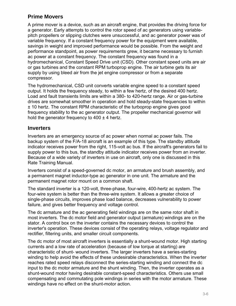
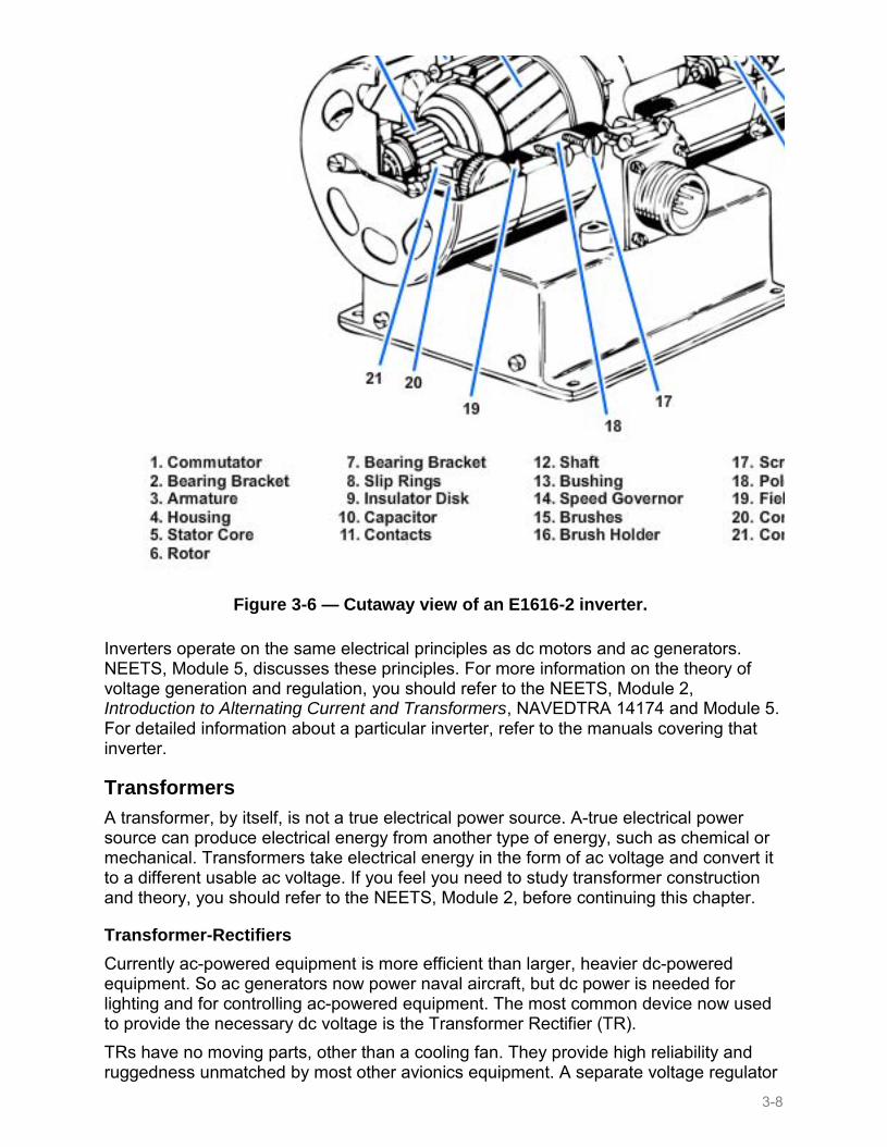
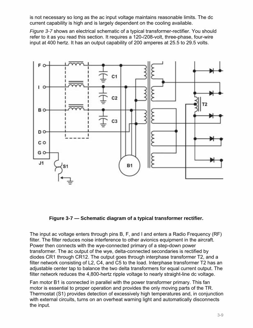
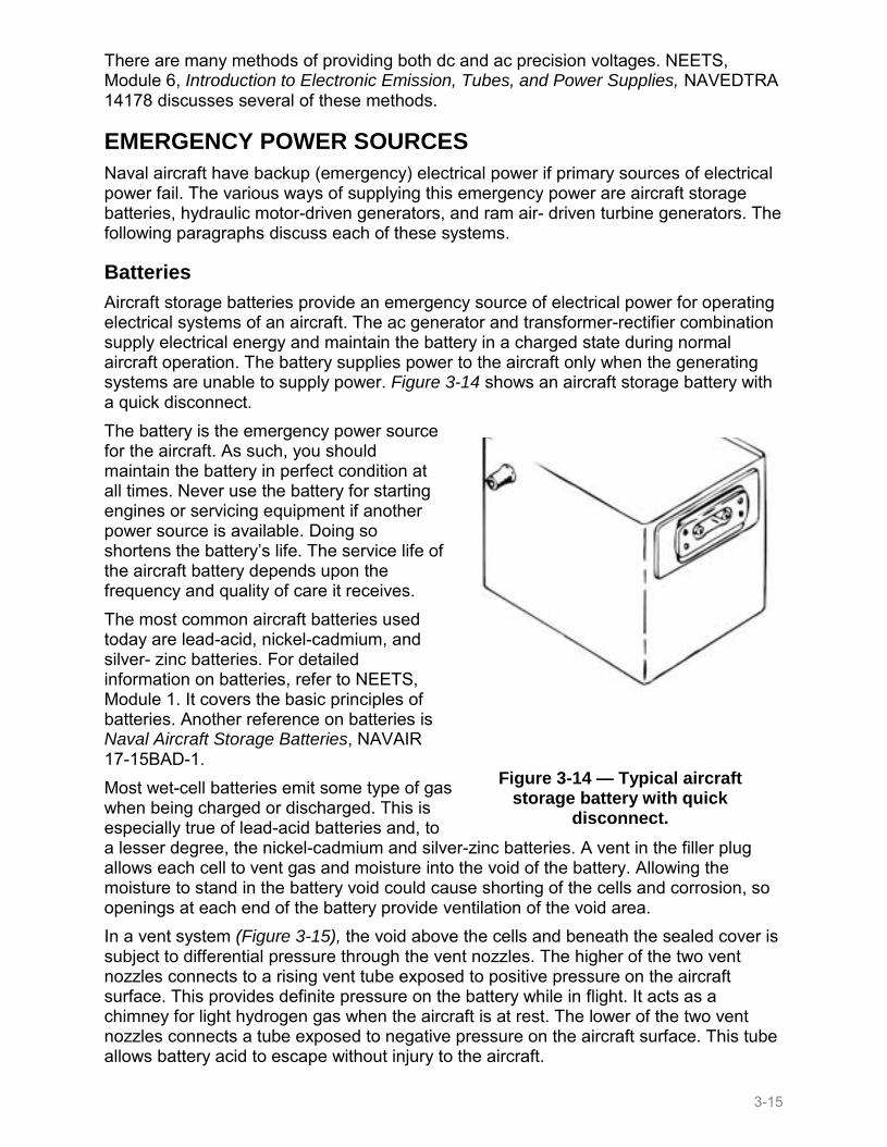
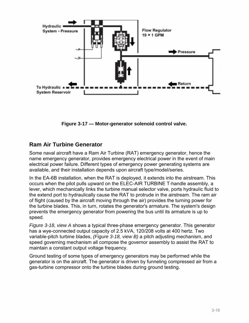
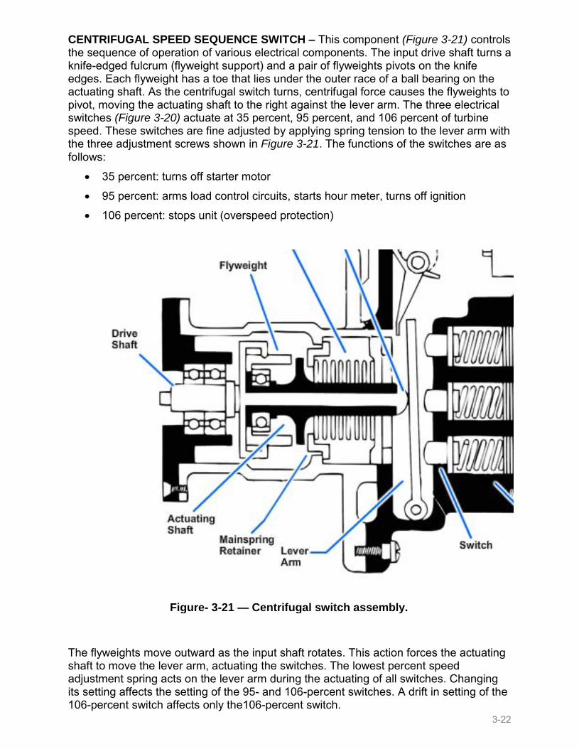

NOTE
Some brushless generators use permanent magnets in the exciter circuits
CONTROLS AND CIRCUIT PROTECTION
The first part of this chapter dealt with the various devices used to provide electrical power in naval aircraft This part deals with methods that regulate the output voltages of ac generators To understand voltage regulation you should be familiar with the principles of ac and dc power generation NEETS covers these principles in detail Before continuing with this chapter you should review the appropriate NEETS modules Two methods of voltage regulation have become popular in recent years The most common method in power-generating systems is varying the current to the generator exciter winding (sometimes called field winding) This in turn changes the size of the magnetic field which changes the voltage output of the generator The second method of voltage regulation is to maintain a constant load on the generator This method uses a permanent magnet on the generator rotor in place of exciter windings which simplifies generator construction This type of regulation must however be used with systems that supply constant loads and have a limited capacity For example an inverter or an electronic power supply uses this type of voltage regulation The regulator varies the resistance of a parallel resistor so total resistance remains constant regardless of the load resistance This type regulator is for use with both ac and dc power sources
AC GENERATOR CONTROL
When magnetic fields of alternating polarity pass across the armature windings ac voltage induction occurs The voltage induced into the windings depends on three things All of the following three things can control the voltage induced into the ac generator windings
1 The number of turns of conductor per winding 2 The speed of the magnetic field passing across the winding (generator RPM) 3 The magnetic field strength
The number of turns per winding and the number of windings is set during generator manufacture The frequency of the output voltage depends on the speed of the generator The strength of the magnetic field controls the level of output voltage In some cases as in tachometer generators a permanent magnet field maintains the load at a constant value In todays aircraft electrical and electronic equipment operate at exact frequencies and voltages Systems exposed to extreme overvoltages or off-frequencies not only destroy themselves but may start a fire during an emergency All ac generator control systems must contain circuits to protect against under voltage and overvoltage under frequency and over frequency and improper phase sequence The generators shown in Figure 3-22 views A and B use an electromagnetic field rather than a permanent magnet-type field
3-24
Figure 3-22 mdash AC generators (A) Brush type (B) brushless type
The current flowing through the field controls electromagnetic field strength Varying the voltage applied across the field helps to control the field strength By varying the dc output voltage from the exciter armature you control the ac generator field strength The value of the generated ac voltage depends directly on the size of the exciter input This relationship allows a small dc voltage to control a much larger ac voltage The rotating threeshyphase rectifiers on the brushless generator help change the ac output of the exciter to dc Then the dc feeds the main ac generator rotating field eliminating the use of brushes
As you have already learned controlling the strength of the magnetic field controls the generated voltage A voltage regulator controls the magnetic field strength Current generating the magnetic field is known as excitation current The auxiliary dc generator (called the exciter) or a rotating three-phase rectified ac exciter generator supplies this current The exciter is on the same shaft as the ac generator to make it an integral part of the generator The present military specification for aircraft ac generators states that they should be self-supporting All dc exciter units are integrated into the ac generators to meet this requirement The chief advantage of exciter units is that each generator has its own independent source of excitation No external source of electric power is necessary for generator operation In a multigenerator installation failure of one generator exciter
3-25
Figure 3-23 mdash Solid-state voltage regulator
does not make the complete system inoperative This would happen if a generator system had a common external excitation system Internal excitation makes it unnecessary to transmit excitation power which reduces the chances of losing excitation from an open or short-circuited wire In contrast to dc generators the magnetic field coils in most aircraft ac generators rotate This induces the ac voltage into the stationary windings A solid-state regulator is a type of voltage regulator that has no mechanical moving parts (except the exciter control relay) The ac generator output flows to the voltage regulator which compares it to a reference voltage The difference supplies the control amplifier section of the regulator (Figure 3-23) If the output is too low regulator circuitry increases the field strength of the ac exciter It reduces the field strength if the output is too high
The power supply for the bridge circuit is CR1 CR1 provides full-wave rectification of the three-phase output from transformer T1 The dc output voltages of CR1 are proportional to the average phase voltages The negative anode of CR1 supplies power through point B R2 point C Zener diode CR5 point D and to parallelshy connected V1 and R1 Takeoff point C of the bridge is located between resistor R2 and the Zener diode The other leg of the reference bridge (resistors R9 R7 and temperature compensating resistor RT1) connects in series with V1 and R1 through points B A and D The output of this leg of the bridge is at point E As voltage changes occur voltage across R1 and V1 (once V1 starts conducting) remains constant leaving the total voltage change occurring across the bridge Because voltage across the Zener diode remains constant (once it starts conducting) the total voltage change occurring in that leg of the bridge is across resistor R2 The voltage change across the resistors is proportional to their resistance values in the bridgersquos remaining leg
3-26
For this reason the voltage change across R2 is greater than the voltage change at point E If the generator output voltage drops point C is negative with respect to point E Conversely if the generator voltage output increases the voltage between the two points reverses polarity The bridge output taken between points C and E connects between the emitter and the base of transistor Q1 With the generator output voltage low the voltage from the bridge is negative to the emitter and positive to the base This is a forward bias signal to the transistor and the emitter to collector current increases The voltage across emitter resistor R11 increases with the increase of current This increase in turn applies a positive signal to the base of transistor Q4 which increases emitter to collector current and increases the voltage drop across emitter resistor R10 This gives a positive bias on the base of Q2 which increases its emitter to collector current and increases the voltage drop across its emitter resistor R4 This positive signal controls output transistor Q3 The positive signal on the base of Q3 increases the emitter to collector current The control field of the exciter generator is in the collector circuit Increasing the output of the exciter generator increases the field strength of the ac generator which increases the generator output An under speed switch located near the F+ terminal prevents generator excitation when the frequency is at a low value The switch closes and allows the generator excitation when the generator reaches a suitable operating frequency Resistors R27 R28 and R29 connect in series with the normally closed contacts of relay K1 The coil of relay K1 connects across the power supply (CR4) for the transistor amplifier Electricity from the 28-volt dc bus goes to the exciter generator field to flash the field for initial excitation when the generator starts turning When the field of the exciter generator energizes and the ac generator output voltage increases relay K1 energizes opening the field flash circuit
3-27
Figure 3-24 mdash Solid-state voltage regulator schematic
Another type of solid-state voltage regulator (Figure 3-24) operates by sensing the voltage existing on the lines
It amplifies the changes in this signal and varies the average current supplied to the field winding of the integral exciter The voltage regulator consists of a sensing circuit with input rectifiers a temperature compensated Zener diode reference and error-detecting bridge and a three-stage transistor amplifier The output of the bridge circuit is a voltage inversely proportional to the difference between generator voltage and regulator set voltage This output is referred to as the error signal Transformer T1 in the regulator supplies three-phase ac generator output It provides isolation from the generator and delivers correct utilization voltages The transformer output passes through the full-wave bridge rectifier (CR1) to obtain a dc voltage to supply the comparison circuit The rectifier output is proportional to the average of the three line voltages The voltage reference and error-detecting bridge uses this voltage for comparison with the constant voltage across the Zener diode (CR5) This achieves a means of telling whether the generator output is too high or too low Potentiometer R7 permits adjustment to the desired voltage The glow tube (V1) serves to increase the sensitivity of the voltage reference and error-detecting bridge Thermistor RT1 provides temperature compensation in the comparison circuit It offsets the effects of changes in other elements of the circuit that result from temperature variations to maintain a nearly constant voltage
3-28
Figure 3-25 mdash Pulse width modulation diagram
The error-detecting bridge output voltage sawtooth wave shape is because of the ripple resulting from the semifiltered three-phase rectifier supply This sawtooth voltage goes to the input of the first stage of the three-stage transistor amplifier Overdriving the second and third stages obtains an essentially square-wave output The effect of the error detecting bridge output is to modulate the width of the pulses passing through the amplifier Varying the output current to the exciter field varies the width of the square-wave impulses Figure 3-25 shows a pulse width modulation diagram As the voltage rises (shown by the dotted back-to-back sawtooth) the square-wave pulse to the exciter field is off longer than it is on This causes the output of the ac generator to decrease The decrease in voltage causes the back-to-back sawtooth to drop to its normal value (shown by the solid waveform) This causes the on and off times of the square-wave pulse to the exciter field to be about equal Varying the on and off excitation to the exciter field controls the ac generator output
Refer to Figure 3-25 as you read this paragraph The power for operating the three-stage transistor amplifier comes through the full-wave bridge rectifier (CR4) from transformer T1 Obtaining amplifier power this way requires special consideration There are conditions that require excitation when no voltage is available to supply the amplifier Such conditions exist during initial buildup of system voltage and during three-phase short circuit on the generator Control relay (K1) connects across the full-wave bridge rectifier (CR4) overcoming these obstacles When the relay is de-energized its contacts provide PMG voltage to the exciter field When generator voltage is 90 volts line to line voltage across CR4 energizes control relay (K1) removing the self-excited field circuit The voltage regulator then supplies the exciter field The absence of phase shift and fast response characteristics of transistor-type amplifiers eliminates feedback networks and stabilizing transformers in this voltage regulator
3-29
Figure 3-26 mdash Simplified CSD functional diagram
Frequency Control
Because of the fixed number of poles the only means of fine tuning the output frequency is controlling rotor RPM CSD units are often used for controlling generator rotor RPM CSDs receive drive power from hydraulic power pneumatic power or the accessory drive section of an engine A CSD unit is located between the aircraft engine and the ac generator in most aircraft for this purpose The purpose of the CSD is to transfer and convert aircraft engine variable-speed rotation to a constant-speed rotation which drives the generator The CSD consists of a variableshydisplacement hydraulic pump constant-displacement hydraulic motor and a governing system The governing system controls the rate of flow from the pump thereby controlling the speed of the motor There are several other components in the CSD that are necessary for self-regulating constant-speed operation Among these components are three output-driven gear pumps the charge pump replenishing pump and scavenge pump A gear on the CSD output shaft drives these pumps the limit governor and basic governor The pump wobbler and the pump section of the cylinder block assembly form the variable displacement pump in the CSD Figure 3-26 shows a simplified CSD functional diagram The pump wobbler consists of an outer stationary shell and an inner race The inner race is separated from the wobbler shell by bearing rollers It is free to turn with the pump pistons which are always in contact with the race during operation Two control pistons in the CSD housing move the wobbler sideways to vary the output of the pump The CSD functions in three different phases of operation They are the overdrive phase straight-through phase and the underdrive phase
3-30
The CSD makes up the difference in RPM when the engine input RPM is less than the RPM required for the generator The CSD does this by causing the pump wobbler system to respond to governor signals This response causes the pump to supply more oil to the motor The difference between the input and output RPM depends on the quantity of oil pumped by regulating the wobbler pump The CSD is in overdrive anytime the motor wobbler (output) is rotating faster than the cylinder block assembly (input) When the input RPM equals the required output RPM the rotary motion transmits through the CSD without hydraulic action The pump wobbler would theoretically be positioned through the action of the governor to be concentric with the cylinder block assembly The pump neither pumps oil to the motor nor accepts oil from the motor in this condition The motor pistons lock in position against the motor wobbler forcing the wobbler to rotate at the same speed as the cylinder block assembly Because the drive starts in underdrive and operates normally in overdrive this straight-through condition is only temporary The CSD acts to subtract from the input rotation when engine input RPM exceeds the output RPM requirements for the generator The wobbler pump accomplishes this in response to the governor signal The pump-motor action for underdrive is the reverse of the action required for overdrive The pump performs in a negative pumping action in the underdrive phase The generator load opposes the driving force of the CSD so it always tries to slow the wobbler The cylinder block assembly then rotates faster than the motor wobbler Excess input torque is dissipated in the reverse pumping action to the charged oil system The CSD is in underdrive whenever the motor wobbler is rotating more slowly than the cylinder block assembly The CSD goes into underdrive to protect the generator from overspeed when the engine overspeeds or if the basic governor fails The underspeed pressure switch in the governor oil line functions to break the electrical circuit of the ac control system The system is protected during an underspeed condition In some CSDs aircraft engine oil from the engine lubricating system is the hydraulic medium In this case the CSD also functions as a pump for supplying the generator with engine oil for cooling Oil-cooled generators are of smaller construction than air-cooled generators having a similar rating because of cooling capabilities
CIRCUIT PROTECTION
The generator and equipment and systems the generator powers need protection if a malfunction occurs Circuits designed to sense malfunctions and energize relays provide protection by either warning the pilot of the malfunction or disconnecting the generator The circuit protection needed and the methods used to control the malfunctions depend on aircraft and equipment design For example in a single-pilot aircraft all malfunction detection and correction might be automatic In a multi-piloted aircraft the generating system may only warn the flight crew of a problem This leaves corrective action to the discretion of the pilot in command A supervisory panel provides regulation and circuit protection for both the operating generator and equipment it powers in newer generating systems This single component provides the same functions as several components in older power generating systems The supervisory panel provides voltage regulation at 120208 volts ac while some types of CSDs provide frequency control at 400 Hz The supervisory panel further has relays and other associated circuitry to disconnect the generator from the load if any of the following conditions occur
3-31
Underfrequency
Overfrequency
Undervoltage
Overvoltage
Feeder fault (A condition where the current leaving the generator does not pass through the load System design has cut out the need for feeder fault protection in systems where it isnt likely to occur)
UNDERFREQUENCY AND OVERFREQUENCY CONTROL
You should refer to Figure 3-27 as you read this section The PMG output is 39 volts at 600 Hz when the generator is on speed The voltage reference bridge and the frequency sensitive bridge sample output voltage and frequency The band-pass filter is tuned to 600 Hz (called its resonant frequency) Its minimum resistance and maximum current flow occur at 600 Hz The output of the bridge networks are equal and opposite at this frequency The underfrequencyoverfrequency sensor senses an on-frequency condition energizing the underfrequencyoverfrequency relay (K1) Current flows through contacts 4 and 6 of energized relay K1 This allows generator control relay (K2) to energize if the frequency remains within tolerance for at least 3 seconds
3-32
Figure 3-27 mdash Generator control system voltage regulatorsupervisory panel
3-33
The band-pass resistance increases and output of the circuits is unbalanced if the PMG frequency changes from the desired 600 Hz The underfrequencyoverfrequency sensor senses the unbalance and causes K1 to de-energize and immediately cuts off SCR-1 K2 de-energizes and disconnects any input to the exciter stator coils and reduces the generator output voltage to zero Contacts 1 and 2 of K1 change frequency tolerance from 600 Hz plusmn 42 to 600 Hz plusmn53 by adding resistance to the voltage reference bridge circuit when K1 energizes This prevents the relay from chattering when the generator is operating at or very near its tolerance limit
VOLTAGE CONTROL
A voltage regulating circuit changes PMG ac voltage to dc voltage and controls its amplitude The voltage regulator senses all three phases of the generator output If the average of these voltages is low dc voltage to the exciter stator coils increases until output voltage is at the desired level If output voltage is high the voltage regulator decreases its output to the exciter stator coils until voltage is within tolerance The generator system maintains three-phase output voltage to 120 volts plusmn 2 through a wide range of loads from 1 to 120 kVA One-phase load may be one-third more than the other two-phase loads and voltage will not vary more than 5 volts between phases It takes 17 amperes of current through the exciter stator coils to produce the desired magnetic field to generate a 120-208-volt 60-kVA load
Undervoltage
Refer to Figure 3-27 as you read this section The undervoltage sensing and control circuit allows generator output to power the distribution system when voltage rises to 105 volts during initial generator buildup However it does not de-energize the generator output until one or more phases fall below 90 volts The undervoltage sensor monitors generator output In conjunction with K1 it also energizes auxiliary control relay (K3) connecting generator output to the power distribution system When K3 energizes its contacts arm a timing circuit that acts automatically when one or more phases are 90 volts or less The timing cycle duration is electronically divided into a 3-second period and a 1-second period in that sequence The two periods are additive The total time involved before an undervoltage trip occurs is about 4 seconds The delay circuitry allows time for corrective measures (circuit breakers or current limiters to open) to remove the cause of the undervoltage The generator stays on line if the cause of the undervoltage is removed and voltage rises to 105 volts before the initial time delay lapses This cancels the lapsed increment and the full 4-second delay is reinstated However after a 4-second delay differential protection latch-out relay (K6) energizes energizing lockout relay (K4) and removes power from K3 and K2 An excessive load on the generator can cause an undervoltage (a short circuit in a system that has a defective circuit breaker or fuse) This condition if allowed to continue could cause a fire or destroy the generator Therefore both K6 and K4 have holding circuits to keep them energized even when the undervoltage condition is corrected To check for correction of the undervoltage use the following procedure
3-34
1 Place the GEN CONTROL SWITCH to the OFF position 2 Pull and reset the GEN CONT circuit breaker 3 Return the GEN CONTROL SWITCH to ON
Overvoltage
As you read this section refer to Figure 3-27 An overvoltage sensor senses line voltage above 129 volts and starts a time delay When started the delay times out for a time inversely proportional to the overvoltage A voltage of 130 volts on a single phase may have a delay of 3 to 4 seconds A large overvoltage on all three phases may have a delay of a few milliseconds When the delay completes timing it triggers SCR2 into conduction and allows K4 to energize An overvoltage occurs if a voltage regulator malfunctions or if a large load (several loads) is removed from the generator at once The voltage regulator is not fast enough to react when the generator loses several loads quickly That is it is possible for an overvoltage to occur during normal operation of the generating system K4 supplying its own holding circuit prevents the generator from powering the load again If you place the GEN CONTROL SWITCH to either the RESET or the OFF position and back to ON the generator stays on line This prevents a generating system with a malfunctioning voltage regulator from cycling on and off
Feeder Fault System
A short occurring between the generator and distribution system would cause a fire because there arent any protective devices (such as circuit breakers and fuses) To protect against this possibility a feeder fault circuit (Figure 3-27) was designed The generator armature winding (output) has current transformers on each side of each winding One set of current transformers (on the grounded side) is as close to the armature windings as possible The other set is as close to the distribution system (and its protective devices) as possible Then the transformers connections are made so the voltages produced cancel each other out The input to the feeder fault sensor would then be nearly zero A short to ground or phase to phase would place a voltage across R2 causing the feeder fault sensor to energize differential protection relay (K7) K7 then acts to energize K6 K6 energizes K4 and K4 de-energizes K2 and K3 Because K7 remains energized by its own contacts using PMG voltage the system cannot be reset until removal of PMG voltage by stopping the generator
Power in AC Circuits
In a dc circuit the equation P = EI is used to compute power For example watts (P) equal volts (E) timersquos amperes (I) If 1 ampere flows in a circuit at a pressure of 200 volts the power is 200 watts The product of the volts and the amperes is the true power in a dc circuit In ac circuit a voltmeter shows the effective voltage and an ammeter shows the effective current The product of these two readings is apparent power Only when the ac circuit is of pure resistance is the apparent power equal to the true power When the impedance of the circuit is either inductive or capacitive current and voltage are not in phase and true power is less than apparent power You obtain true power by using a wattmeter to read the system The power factor is the ratio of true power to apparent power and is equal to true power divided by apparent power
3-35
Figure 3-28 mdash Three-phase ac bus
Equipment using ac power should have as near a unity power-factor load as practicable This improves the efficiency of power distribution by reducing the line current and 12 R (power) losses Most ac loads in an aircraft are somewhat inductive resulting in a lagging power factor Power-factor corrections are made by connecting a capacitor of the proper capacitance in parallel with the circuit Make the connection as close to the inductive load as possible The non-energy component of the current in the inductive branch is 180˚ out of phase with the capacitive current These currents circulate between the capacitor and inductive load and do not enter the line The vector sum of capacitor current and total inductive load current is equal to line current The line current is now in phase with the applied voltage to the parallel combination of the inductive load and the capacitor This reduction in line current reduces line loss and increases the efficiency of transmission Additional information on power factor and power-factor correction is found in NEETS Module 2 Introduction to Alternating Current and Transformers NAVEDTRA 14174 Refer to it if you need to review this topic
Power Distribution
You have learned that various sources are used to provide electrical power to operate aircraft electrical equipment and systems In this section the system that connects the electrical power source to the equipment is discussed Each manufacturer develops a system that meets the needs of their particular aircraft design A system of priorities ensures certain critical equipment is operable if there is a malfunction For example if a power lead used to start an engine shorted out during flight it is inappropriate to sacrifice all electrical power especially power to lighting navigation equipment flight instruments and other essential equipment Therefore systems of like priority are on a common line called a bus Each type of aircraft has a group of buses identified by the priority of the equipment it powers For example a flight-essential bus may power emergency lighting critical flight and engine instruments andor an emergency radio Less important critical equipment receives power from an essential bus Normal systems used to complete the assigned mission or provide crew comfort are on the main bus The input to a bus may be either dc or ac The output from the bus has a protective device such as a circuit breaker fuse or current limiter A three-phase ac bus has three separate common lines one for each phase (Figure 3-28) Sometimes schematics show three phases drawn as one line
3-36
Figure 3-29 mdash Simplified P-3C electrical power distribution
The P-3C aircraft is an example of versatility and flexibility in electric systems Figure 3-29 shows a portion of the P-3C power distribution system
Operation of the P-3C electrical power distribution system during normal flight conditions is entirely automatic The crew only monitors the control panel for any indication of a malfunction Control of the system is also automatic during ground operation except switching to and from external power
3-37
POWER SOURCES
This section contains a discussion of a representative power distribution system used in FA-18 Super Hornet aircraft Electrical power is provided to the electrical power distribution system buses from these sources
1 Left generator 2 Right generator 3 External power
Two engine-driven Airframe Mounted Accessory Drives (AMAD) supply the mechanical driving force to turn two 5065 kVa115200vac three-phase four-wire wye connected 400Hz Variable Speed Constant Frequency (VSCF) generating systems The generators work to supply electrical power both in engine start mode and ground maintenance mode The two generators connected to independent buses supply electrical power to the essential non-essential and maintenance buses Either of the generators can supply the entire electrical demand of the aircraft in the event one generator fails Two power supplies supply the dc power The power supplies convert 115vac to 28vdc for power distribution used as the primary dc system The generators send direct dc voltage to the Power Distribution Panels (PDP) as an Essential Bus Backup (EBB) Additionally a battery system also provides the maintenance bus dc power as a secondary backup if either power supply fails Either power supply is capable of supplying the entire dc requirements of the aircraft
AC Bus Distribution System
The distribution system consists of sixteen PDP two essential circuit breaker panels and a multitude of Relay Module Assemblies (RMA) which comprise the electrical system
1 Left main 115vac bus 2 Right main 115vac bus 3 26vac bus
The left and right 115vac buses and the 26vac bus through a split bus distribution network distribute internal external power through the ground power distribution system and ground power switching system A set of four magnetically held ground power (GND PWR) switches which minimizes operating time on selected equipment control external input power to components and systems Internal power is provided by the two generators and external power provided by a deck edge source or power cart The power distribution system provides the essential buses and PDPs the required ac and dc power to aircraft systems
DC Bus Distribution System
The main sources of dc power are the left and right power supplies The left and right power supplies provide primary dc power by converting 115vac 3-phase and 400 Hz power from their respective generators to power the left and right 28vdc bus in PDPs 1 and 6 The left and right 28vdc buses provide power to the dc essential bus A 28vdc output is provided as EBB power when both generators are operating Both power supplies are powered through bus tie circuitry with a single generator failure The maintenance battery a secondary dc power source supplies power to the essential
3-38
NOTE
Pins E and F are jumpered in the external power cable plug
and maintenance buses The battery is controlled by a magnetically held battery (BATT) switch and has voltmeter readout of maintenance battery when the ac buses are not powered The voltmeter indicates battery charger converter voltage when ac buses are powered
Operation
As you have already learned two generators and two power supplies or an external ac power source provide electrical power During ground operations operating in the Ground Maintenance Mode (GMM) or external electrical power can supply electrical power to the aircraft electrical systems by using ground power switching where power is optimized by selecting the systems needed for testing and troubleshooting If engines are operating and hydraulic pressure available the generators are a useable source of power and ground power switching functionality is disabled
External Power
The external electrical power system permits application of three-phase ac power to the aircraft electrical power distribution system (Figure 3-30) Three-phase external power goes to the external power monitor and contacts A1 B1 and C1 of the external power contactor The power monitor prevents application of external power not within tolerances If an undervoltage an overvoltage an underfrequency an overfrequency and phasing condition exist the power monitor disconnects external power from the power distribution system When all the power parameters are within tolerance the external power monitor switch control relay energizes supplying 28vdc from the external power monitor rectifier through the external power (EXT PWR) switch lower contacts to pin F of the external power receptacle
3-39
Figure 3-30 mdash External ac power and ground power switching functional block diagram
3-40
The power then runs through pin E and energizes the coil in the external power contactor Then three-phase power from the external power cable is provided to contacts A2 B2 and C2 through the energized contacts of the external power contactor which powers the left 115vac bus and right 115vac bus through their respective contactors Note the right bus tie contactor shown energized powers the right 115vac bus The right 115vac bus will not be powered when the battery switch is set to ON and the PARK BRAKE is released Power from the left 115vac PDP No 5 bus goes to power the left power supply and the right 115vac bus PDP No 2 goes to power the right power supply PDP No 2 also powers the 26vac transformer assembly to provide step down phase C voltage for other various aircraft components After engine start and the left generator comes on line (L GEN light extinguishes) the left power contactor automatically disconnects external power The indications of external power application cease when the respective generator light goes out and the ground power switches reset to the auto position because of operating on internal power At that time the only control the pilot has over external power being applied or removed is the hand signals between the pilot and the plane captain
Ground Power Switching Operation
During external power application (Figure 3-30) the EXT PWR control switch is set to RESET then back to NORM and the external power contactor energizes L 28vdc bus power from PDP No 1 is routed to the GND PWR switches through the energized contacts of external power contactors and the de-energized contacts of left and right power contactors The energized external power contactor connects negative side of ground power relays with respect to ground When GND PWR switches in AUTO position (shown) 28vdc is routed to the ground power switches contacts The holding coils energize whenever any ground power switch is set to A ON or B ON 28vdc is then routed from the ground power switch contacts to the positive side of coils of the ground power relays and the ground power fault sensing relays The energized ground power relays de-energize the controlled equipment With any ground power switch (except for 4 to A ON) set to A ON or B ON for 3 seconds and no overheat condition exists (avionics cooling supplied) 28vdc is removed from respective ground power relays The de-energized relays apply power to specific equipment which is controlled by ground power switch relays A ground is routed to the respective switch holding coil from the external power contactor through energized undercool warning relay The under cool warning relay is energized when no overheat condition exists Depending which ground power switch is actuated the holding coil will energize holding the switch in selected position either A or B ON If ground power is interrupted for any reason the external power contactor will de-energize and the holding coils de-energize thus returning all GND PWR switches to the AUTO position If an avionics overheat condition exists the under cool warning relay de-energizes and all grounds are removed from the holding coils The holding coils will de-energize and the GND PWR switches return to the AUTO position With ground power switch 4 placed to A ON position the holding coil receives ground directly from external power contactor The holding coil will not de-energize if avionics overheat condition exists Systems controlled by ground power switch 4 to A ON do not need cooling air
3-41
Figure 3-31 mdash Simplified ac power distribution schematic
Main Generators
Refer to Figure 3-31 With external power connected and the left engine start is initiated the left AMAD mechanically turns the left generator and the left generator comes on line when all parameters are within tolerance Momentarily the L GEN light on the caution light indicator panel extinguishes The left power contactor energizes with the left generator online The left generator now supplies power through the left power contactor contacts A1 and A2 to the left 115vac buses at PDPs No 5 and 9 Additionally through the energized contacts of the right bus tie contactor contacts A2 to A1 and through the de-energized contacts of the right power contactor contacts A2 to A3 the right 115vac bus in PDPs No 2 and 8 are energized The left and right 115vac buses No 2 and 5 in turn provide 115vac power to the left and right power supplies and the phase C 26vac bus
The left power contactor removes external power from the aircraft bus system when it energizes The external power unit is now shut down and the cable removal may be done safely After right engine start is initiated and the right generator is on line the right power contactor energizes allowing the right generator to power the right 115vac bus at PDP No 2 The energized contacts of the right power contactor contacts A1 to A2 prevent the left generator from powering the right 115vac bus Likewise the energized left power contactor contacts A1 to A2 prevents the right generator from applying power to the left 115vac bus
3-42
Figure 3-32 mdash Simplified dc power distribution schematic
For primary flight control operation the generators provide the required 28vdc power to the flight control computers from the two isolated PMGs and converter regulators through switching relays The generator will shut off the respective 28vdc output if the 28vdc output voltage does not meet designated output criteria In the event 28vdc shuts down the flight control system circuits receive power from the essential buses powered by the left or right power supplies or maintenance battery The left power supply (Figure 3-32) receives power from the left 115vac bus PDP No 5 for primary dc power operation The left power supply provides primary dc power to the left 28vdc bus and essential and maintenance buses One generator supplies both power supplies through bus tie circuitry The right primary dc bus is connected to the left primary dc bus through two dc bus tie current limiters The left or right primary dc buses power the essential bus through the de-energized contacts of the battery contactor contacts A3 to A2 The functioning power supply supplies all dc loads through the dc bus tie current limiter holders during a single-power supply failure The maintenance battery supplies power to essential dc loads during a dual-power supply failure
The generators provide the 28vdc essential bus backup for essential bus back up operation They are supplied by isolated PMG and converter regulators contained inside the generator The right generator is primary EBB power supply source for the 28vdc system and supplies the dc power during dual power supply failure The left generator supplies EBB power during a dual power supply and right generator failure through the
3-43
de-energized right EBB contactor contacts A2 to A3 The secondary source of dc EBB power is either the left or right generator where either generator supplies all the essential dc bus loads The left or right generator energizes the respective EBB contactor If no faults are present 28vdc EBB power is routed through energized contacts of the battery contactor to the essential dc buses If faults are present the signal data computer sends the data to the mission computer when a 28vdc power source can no longer provide flight control or EBB power and the mission computer commands the left digital display indicator to display L or R DC FAIL caution For secondary dc power (Figure 3-32) to the essential buses the secondary dc power source is the maintenance battery The maintenance battery supplies power to essential loads when the right 28vdc bus is not powered With BATT switch set to ON aircraft weight-on-wheels APU control switch set to OFF and the right dc bus not powered one minute time delay battery cutoff relay applies 28vdc to the holding coil of the battery switch The coil of the battery cutoff relay energizes one minute after power is applied The battery contactor energizes and powers the essential dc buses after relay switching operation is complete This operation which is used for extracting maintenance monitor panel codes from the nose wheel digital display indicator is used mainly by maintenance personnel The right generator provides power to the right 115vac bus The right 115vac bus provides power to the right power supply The right 28vdc bus receives power from the right power supply and is connected to the left 28vdc bus through two bus tie current limiter holders and powers the essential buses The bus is not affected by a loss of either generator or either power supply because the bus receives power from both power supplies
Component Failures
The power distribution system design ensures power is available to operate all aircraft equipment This includes all equipment essential to accomplish the assigned mission and ensure safety of flight Power must be available for continued safe operation if a component or engine should fail The distribution system design provides a continuous power source under all adverse conditions As you know either of the generators is capable of supplying the entire load of the aircraft A master reset for any failed generator is provided by the electrical power control panel Likewise either of the power supplies is able to supply the entire dc load Adverse conditions that could occur in the aircrafts electrical systems include the following
Left generator failure
Right generator failure
Left power supply failure
Right power supply failure The following paragraphs discuss each adverse condition Refer to Figure 3-31 and Figure 3-32 as you read about each condition LEFT GENERATOR FAILURE ndash When the left generator drops off line the left power contactor de-energizes The right generator powers the left 115vac buses through the energized left bus tie contactor the de-energized external power contactor and de-energized left power contactor Left and right ac buses receive 115vac power RIGHT GENERATOR FAILURE ndash When the right generator drops off line the right power contactor de-energizes The left generator powers the right 115vac bus through
3-44
Figure 3-33 mdash Grounded system
the energized left power contactor and energized right bus tie contactor and de-energized right power contactor to the right 115vac buses Left and right ac buses receive 115vac power LEFT POWER SUPPLY FAILURE ndash When the left power supply fails the left 28vdc bus PDP No 1 is powered from the right power supply through both the left and right dc bus tie current limiter holders The functioning power supply supplies all the dc loads through the de-energized battery contactor thus powering the dc essential buses There is no crew station warning of a single power supply failure RIGHT POWER SUPPLY FAILURE ndash When the right power supply fails the right 28vdc bus PDP No 6 is powered from the left power supply through both the left and right dc bus tie current limiter holders The functioning power supply supplies all the dc loads through the de-energized battery contactor powering the dc essential buses In case of the loss of both power supplies the 28vdc maintenance battery provides power to the essential buses through the energized battery contactor As shown the power distribution system maintains its integrity with a loss of either generator or power supply This ensures all systems are available for safe flight and mission accomplishment
Grounded Systems
The term grounded system means that one leg of the system connects to a common conductor This common conductor can be the earth the skin of the aircraft or to a structural member of the aircraft This conductor may serve as one leg of the circuit when the grounded leg of the circuit connects to a good electrical conductor This cuts out the need for a separate conductor for this leg of the circuit Figure 3-33 shows a simple grounded system Even though the grounds are at different points the potential at these points is the same because they connect to a common conductor The letter N designates any wire that completes the equipment circuit to the ground network Any wire designated as N may come in contact with ground at any point without causing the equipment to malfunction Grounding three-wire systems can be done by grounding one of the phases usually the B-phase in aircraft Make sure you ground the same phase in all equipment Figure 3-34 shows the grounded three-phase systems In four-wire systems the neutral is ground
3-45
Figure 3-34 mdash Grounded three-phased
systems
The grounded circuit is better than the ungrounded one because it reduces overall weight by using fewer conductors This results in a reduction in cost and space requirements Other advantages are that troubleshooting is simplified and the impedance of the ground return path is lower than that of a run conductor A disadvantage of a grounded system is that short circuits result when a bare spot on any ungrounded conductor touches ground Another disadvantage is having circuits of different potentials and frequencies use a common ground There is a possibility of one circuit feeding into another This problem often happens in electronic circuits
Ungrounded Systems
The term ungrounded system means that the circuit in no way connects to ground All conductors run from the power source to the loads Circuits of this type are often referred to as being above ground The ungrounded system has one advantage mdash it prevents one circuit from feeding into another because the circuits are completely insulated from each other The system has the disadvantage of adding more weight because it requires more conductors than the grounded system This results in added cost and space requirements Both the grounded and ungrounded systems are used for specific purposes in modern aircraft
Single-Phase and Polyphase Systems
Single-phase systems are of simple design and construction They are used when there are relatively low power requirements Polyphase systems are more complicated in construction and design These systems are used when high power is required These systems provide a smoother source of power Single-phase power is available from polyphase systems The load on the polyphase system must be kept balanced when doing this
3-46
End of Chapter 3
POWER GENERATION AND CONTROL SYSTEMS
Review Questions 3-1 What unit converts mechanical energy into electrical energy
A Engine B Power transformer C Generator D Converter
3-2 The use of what system resulted in better avionics systems design and use
A AC power B DC power C Hertz D Volt
3-3 The generator output frequency varies directly in proportion to ________
A inch-pounds of torque B inertia of engine C engine drive speed D overspeed
3-4 What are the two types of ac generators
A Stationary and brushless B Permanent magnet and oil-cooled C Magnetic and three-phase D Brush and brushless
3-5 To accomplish voltage regulation in ac generators you control the strength of
________
A the RPM B the magnetic field C the output winding D the two-separate phase
3-6 A three-phase generator contains how many separate power sources
A One B Two C Three D Four
3-47
3-7 What is the phase difference between voltages in a three-phase generator
A 110 degree B 115 degree C 120 degree D 210 degree
3-8 What unit provides control voltages and power for voltage regulation
A Rectifier B Exciter C Exciter armature D Permanent magnet generator
3-9 Feeder fault protection is provided by ________
A two three-phase differential transformers B generator mechanical failure warning device C control the rotor speed D constant speed output
3-10 The device that provides the driving force for a generator is known as ________
A transformer B prime mover C mechanical governor D inverter
3-11 What unit uses a dc motor to drive an ac generator and is used during
emergency situations
A Permanent magnet generator B Permanent magnet rotor C Inverter D Transformer
3-12 What is the only moving part in a transformer rectifier
A Inverter B Armature C Brush assembly D Cooling fan
3-13 An autotransformer offers its greatest savings at a turn ratio of ________
A 1 to 1 B 2 to 1 C 3 to 1 D 4 to 1
3-48
3-14 What unit is used to connect meters to high voltagecurrent systems
A Autotransformers B Brush C Full wave rectifiers D Instrument transformers
3-15 What are the three most common aircraft batteries in use today
A Wet-cell vent-sump and lead-acid B Vented cadmium and silvershyzinc C Lead-acid nickel-cadmium and silvershyzinc D Storage lead-acid and cadmium
3-16 The ram-air generator is powered by ________
A air caused by aircraft moving through atmosphere B air-pressure surrounding aircraft C variable pitch blade D three-phase emergency generator
3-17 The GTCP-95 centrifugal switch shuts down the unit at what percent RPM
A 35 B 75 C 95 D 106
3-18 What are the two common methods used for voltage regulation
A Maintaining the voltage to the generator exciter winding and decreasing the load on the generator
B Varying the current to the generator exciter winding and maintaining a constant load on the generator
C Varying the current to the generator and varying the load on the generator D Increasing the voltage and the load on the generator exciter windings
3-19 During what conditions will a supervisory panel disconnect the generator from the
load
A Voltage reaches 120208 volts ac B Underfrequency C Engine lubrication system is on D Engine overspeeds
3-20 What is the permanent magnet generator (PMG) output
A 39 volts B 60 volts C 90 volts D 120 volts
3-49
3-21 How much current is used to produce the desired magnetic field to generate a 120-208-volt 60-kVA load
A 5 amperes B 10 amperes C 12 amperes D 17 amperes
3-22 With one phase load one-third more than the other two phases the voltage
between phases should not vary more than
A 5 volts B 5 volts C 120 volts D 208 volts
3-23 The undervoltage protection circuit allows the generator to assume the load at
what voltage
A 105 B 120 C 210 D 300
3-24 What is the length of the undervoltage timing cycle
A 2-second period and a 1-second period B 3-second period and a 1-second period C 3-second period and a 4-second period D 4-second period and a 6-second period
3-25 What voltage will the overvoltage protection circuit start a time delay
A Below 105 B Between 110 and 120 C Between 120 and 128 D Above 129
3-26 What is a feeder fault
A A pump for supplying the generator with engine oil for cooling B Circuit protection for both the operating generator and equipment it powers C A condition where the current leaving the generator does not pass through
the load D A voltage regulating circuit and control
3-50
3-27 What is the power factor in ac circuits
A Resistance is the apparent power equal to the true power B Currents circulate between the power capacitor and inductive load C The ratio of true power to apparent power and is equal to true power
divided by apparent power D The vector sum of capacitor current and total inductive load current is equal
to line current
3-28 How are power-factor corrections accomplished
A By connecting a capacitor of the proper capacitance in parallel with the circuit
B By using a wattmeter to read the system C By making connection as far as possible from the inductive load D By ensuring the capacitor inductive load does not enter the line
3-29 What unit prevents external power that is not in tolerance from being applied to
the FA-18 aircraft
A Right power contactor B Left bus tie contactor C External power monitor D External power contactor
3-30 When the left power supply fails in the FA-18 aircraft which components allow
power to the left side of the dc bus distribution system
A Utility power receptacle and left 115vac bus B Left and right bus tie current limiter holders C Left 115vac bus and left primary dc bus D Right power supply and the battery charger
3-31 During ground power switching operation what is the condition of the left and
right power contactors when external power is applied to the aircraft
A Energized B On line C Negative with respect to ground D De-energized
3-32 What does the term grounded system mean
A When the grounded leg of the circuit does not connect to a good electrical conductor
B The ac essential and dc essential buses receive power C One leg of the system connects to a common conductor D When all the wires complete the equipment circuit to the ground network
3-51
3-33 What does the letter N designates in wire numbering
A Unfiltered unregulated wire B Reference wire for the primary circuit network C Wire for the auxiliary network circuits D Wire that completes the equipment circuit to the ground network
3-34 In the four-wire generator system which lead connects to ground
A B phase B Neutral C De-energized D Energized
3-35 Why is the grounded circuit more advantageous than the ungrounded circuit
A Circuits of different potentials and frequencies use a common ground B It runs the power source directly to the loads C Short circuits result when a bare spot on any ungrounded conductor
touches ground D Because it reduces overall weight by using fewer conductors
3-36 What is an advantage of the ungrounded circuit
A Troubleshooting is simplified and the impedance of the ground return path is lower than that of a run conductor
B There is a possibility that one circuit feeds another C It prevents one circuit from feeding into another D It requires more conductors than the grounded system
3-52
RATE TRAINING MANUAL ndash USER UPDATE
CNATT makes every effort to keep their manuals up-to-date and free of technical errors We appreciate your help in this process If you have an idea for improving this manual or if you find an error a typographical mistake or an inaccuracy in CNATT manuals please write or email us using this form or a photocopy Be sure to include the exact chapter number topic detailed description and correction if applicable Your input will be brought to the attention of the Technical Review Committee Thank you for your assistance Write CNATT AV Rate Training Manager 230 Chevalier Field Avenue
Pensacola FL 32508 COMM (850) 452-9700 utilize voice directory for AEAT Rate Training Manager DSN 922-9700 utilize voice directory for AEAT Rate Training Manager
E-mail Refer to NKO AE rate training web page for curent contact information
Rate____ Course Name_____________________________________________
Revision Date__________ Chapter Number____ Page Number(s)____________
Description _______________________________________________________________
_______________________________________________________________
_______________________________________________________________
(Optional) Correction _______________________________________________________________
_______________________________________________________________
_______________________________________________________________
(Optional) Your Name and Address _______________________________________________________________
_______________________________________________________________
_______________________________________________________________
3-53
- CHAPTER 3
- POWER GENERATION AND CONTROL SYSTEMS
-
- LEARNING OBJECTIVES
- AIRCRAFT ELECTRICAL POWER SOURCES
-
- AC Generators
-
- Types of AC Generators
-
- Prime Movers
- Inverters
- Transformers
-
- Transformer-Rectifiers
- Autotransformers
- Instrument Transformers
-
- Electronic Power Supplies
-
- EMERGENCY POWER SOURCES
-
- Batteries
- ACDC Hydraulic Motor-Driven Generators
- Ram Air Turbine Generator
-
- AUXILIARY POWER UNITS
- EXTERNAL POWER SOURCES
- CONTROLS AND CIRCUIT PROTECTION
- AC GENERATOR CONTROL
-
- Frequency Control
-
- CIRCUIT PROTECTION
- UNDERFREQUENCY AND OVERFREQUENCY CONTROL
- VOLTAGE CONTROL
-
- Undervoltage
- Overvoltage
- Feeder Fault System
- Power in AC Circuits
- Power Distribution
-
- POWER SOURCES
-
- AC Bus Distribution System
- DC Bus Distribution System
- Operation
- External Power
- Ground Power Switching Operation
- Main Generators
- Component Failures
- Grounded Systems
- Ungrounded Systems
- Single-Phase and Polyphase Systems
-
- End of Chapter 3
- POWER GENERATION AND CONTROL SYSTEMS
-
- Review Questions
- RATE TRAINING MANUAL ndash User Update
-
- Button2
- Button1
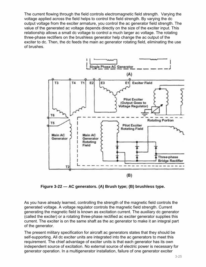
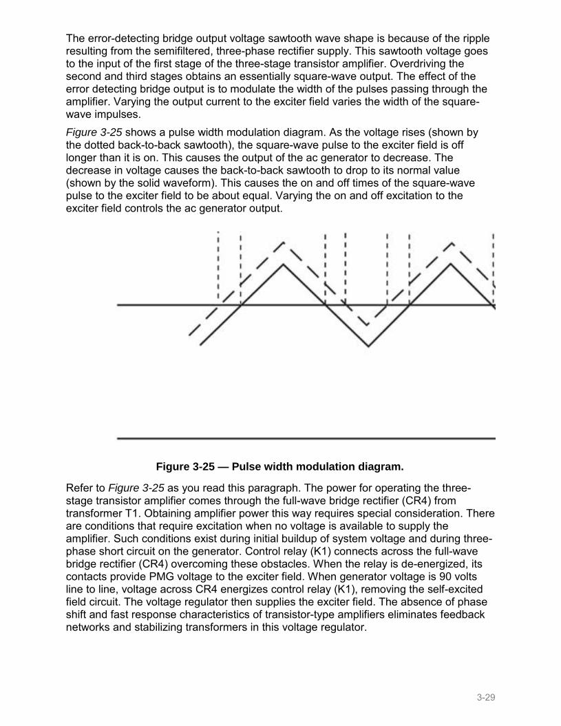
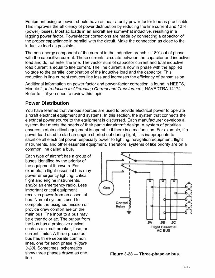
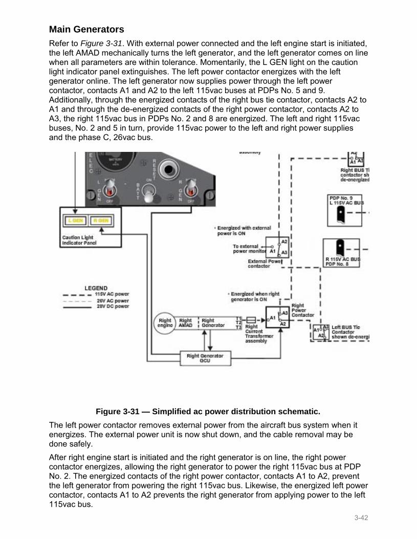
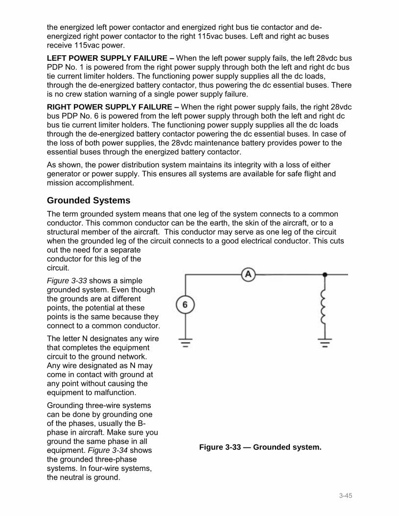