chapter 3 ship compartmentation and watertight integrity · pdf filechapter 3 ship...
TRANSCRIPT

CHAPTER 3
SHIP COMPARTMENTATION AND WATERTIGHTINTEGRITY
Learning Objectives: Recall the definitions of termsused to define the structure of the hull of a ship and thenumbering systems used for compartment numberdesignations. Identify the different types of watertightclosures and recall the inspection procedures for theclosures. Recall the requirements for the three materialconditions of readiness, the purpose and use of theCompartment Checkoff List (CCOL) and damagecontrol closure log, and the procedures for checkingwatertight integrity.
A ship’s ability to resist sinking after sustainingdamage depends large ly on the ship’scompartmentation and watertight integrity. Whenthese features are maintained properly, fires andflooding can be isolated within a limited area. Withoutcompartmentation or watertight integrity, a ship facesalmost certain doom if it is severely damaged and theemergency damage control (DC) teams are notproperly trained or equipped.
In this chapter, you will be introduced tocompartmentation, material conditions of readiness,
watertight integrity, and how they relate to each other.You will also learn about compartment checkoff lists,the DC closure log, the proper care of access closuresand fittings, compartment inspections, the ship’s draft,and the sounding and security patrol watch. Theinformation in this chapter will assist you incompleting your personnel qualification standards(PQS) for basic damage control.
COMPARTMENTATION
Learning Objective: Recall the definitions of termsused to define the structure of the hull of a ship and thenumbering systems used to identify the differentcompartments of a ship.
The compartmentation of a ship is a major featureof its watertight integrity. Compartmentation dividesthe interior area of a ship’s hull into smaller spaces bythe use of structural members.
Refer to figure 3-1 while reviewing the informationon structural members.
3-1
Figure 3-1. Illustrative hull structure.
The keel is the backbone of the ship. The keel doesnot extend below the ship’s bottom. Its usual shape isthat of an I-beam. All other members used inconstructing the hull are attached, either directly orindirectly, to the keel.
The athwartship structure consists of transverseframes and floors. The floors run outboard from thekeel to the turn of the bilge (where the bottom turnsupward). This is where they are attached to thetransverse frames that extend upward to the main deck.
Frames, running parallel with the keel, are knownas longitudinal frames. From the turn of the bilge upthe sides, they are called stringers. The network offloors and longitudinal members resembles ahoneycomb and is known as cellular construction,which greatly strengthens the bottom. When platingcovers the honeycomb structure, double bottoms areformed. The space between the inner and outerbottoms (known as tanks) is used for liquid stowage.The forward end of the keel is extended upward in thestem. The after end has a similar extension, called thesternpost. The part of the stem above water is the prow;the forward edge of the stem is the cutwater.
The interior of a ship is divided into compartmentsby vertical walls, called bulkheads, which run bothtransversely and longitudinally. Most bulkheads aremerely partitions, but transverse watertight bulkheadsare spaced at appropriate intervals. These structuralbulkheads extend from the keel to the main deck andfrom side to side. They provide extra transversestiffening and partition the hull into independentwatertight sections. Large ships have a series oflongitudinal side bulkheads and tanks that provideprotection against torpedoes. The outer tanks usuallyare filled with oil or water. The inner tanks, which arecalled voids, are empty. The innermost bulkhead iscalled a holding bulkhead. When a torpedo hits, theouter tanks, although ruptured, absorb enough energyfrom the explosion that the holding bulkhead willremain intact. This helps to prevent flooding of thevital spaces.
The hull plating is fastened to the framework inlongitudinal rows, called strakes. The keel forms thecenter strake. The strakes are lettered, beginning withthe A-strake on either side of the keel and extending upto the main deck. Some of the strakes also have names.The A-strake is called the garboard strake; the strakealong the turn of the bilge is the bilge strake; theuppermost strake is the sheer strake.
As stated, the projecting keel, running along thebottom near the turn of the bilge, is called the bilgekeel. The purpose of the bilge keel is to reduce rollingof the ship.
NOTE
A ship rolls from side to side. A shippitches when it goes up and down fore and aft.A ship yaws when the bow swings to port andstarboard because of wave action.
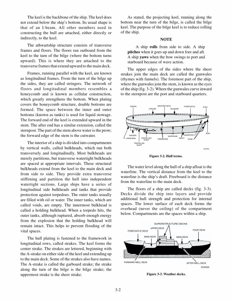
The upper edges of the sides where the sheerstrakes join the main deck are called the gunwales(rhymes with funnels). The foremost part of the ship,where the gunwales join the stem, is known as the eyesof the ship (fig. 3-2). Where the gunwales curve inwardto the sternpost are the port and starboard quarters.
The water level along the hull of a ship afloat is thewaterline. The vertical distance from the keel to thewaterline is the ship’s draft. Freeboard is the distancefrom the waterline to the main deck.
The floors of a ship are called decks (fig. 3-3).Decks divide the ship into layers and provideadditional hull strength and protection for internalspaces. The lower surface of each deck forms theoverhead (never the ceiling) of the compartmentbelow. Compartments are the spaces within a ship.
3-2
FANTAILLIFELINE
WEATHER DECK
BULWARKFORECASTLE EYES
OVERHANG
RUDDER
FREEBOARD
WATERLINEDRAFT
HAWSEPIPE
STEM
BOW
PROPELLERSTRUT
PROPELLERSHAFT
DCf0302
Figure 3-2. Hull terms.
SUPERSTRUCTURE DECKS
UPPER DECKFORECASTLE DECK
MAIN DECK MAIN DECK
POOP DECK
FORWARD WELL DECK AFTER WELL DECK
DCf0303
Figure 3-3. Weather decks.

A steel deck is made of strakes running fore andaft. The outboard strake in the deck plating iscomposed of stringer plates, which are welded orriveted to the side plates and are, therefore, importantstrength members. Decks are supported by transverseframes (deck beams) and by longitudinal (deck)girders. Vertical steel pillars that are called stanchionsprovide other means of deck support. These aremounted one above the other or one above a strengthbulkhead. (The short posts used as lifeline supportsalso are called stanchions.) Decks usually are archedfrom the gunwale to the centerline to provide fordrainage of water and to strengthen the deck.
A deck or part of a deck exposed to the weather iscalled a weather deck (fig. 3-3). Bulwarks are solidfencing along the gunwale of the main (weather) deck.Bulwarks are fitted with freeing ports (scuppers) toallow the water to run off during heavy weather.
A deck that extends from side to side and stem tostern is a complete deck. In aircraft carriers theuppermost complete deck is the flight deck, from whichaircraft take off and land. In all ships (except for aircraftcarriers) the uppermost complete deck is the main deck.In aircraft carriers the hangar deck is the main deck. Thehangar deck is the deck on which aircraft are stowed andserviced when not on the flight deck.
The first complete deck below the main deck is thesecond deck (fig. 3-4), the next the third, the next thefourth, and so on.
A strength deck is a complete deck (usually themain deck) designed to carry not only deck loads on itbut also the hull stresses. The damage control deck is thelowest deck having access through the main transversebulkheads, from forward to aft. The main repairequipment and the principal facilities for the control of
flooding, sprinkling, and pumping under conditions ofdamage are located on the damage control deck. The DCdeck is either the second or third deck on most ships.
The definition and location of the decks in modernships (figs. 3-3 and 3-4) are as follows:
FORECASTLE (pronounced folk’sul): Forwardsection of the main deck, generally extending from thestem aft to just abaft the anchor windlass.
HALF DECK: Any partial deck between completedecks.
PLATFORMS: Partial decks below the lowestcomplete deck. They are usually broken to admitmachinery or other spaces and are called platformdecks or just platforms. They are numbered downward,as first platform, second platform, and so on.
FLATS: Plating or gratings installed only toprovide working or walking surfaces above bilges.
LEVELS: Level is a general term used to designatedeck heights above the main deck. The first level abovethe main deck is the 01 (pronounced oh-one) level, thesecond the 02 level, and so on. Different decks at aparticular level, however, carry different names. Forexample, both a poop deck and a boat deck (usually) areon the 01 level.
UPPER DECK: A partial deck extending from sideto side above the main deck amidships. It is part of thesuperstructure, which is the part of a ship’s structureabove the main deck, exclusive of masts, yards, stacks,and related parts. The side plating extends upward tothe upper deck.
SUPERSTRUCTURE DECK: A partial deckabove the main, upper, or forecastle deck that does notextend to the sides of the ship (if it does, it does nothave the side plating carried up to it.).
3-3
Figure 3-4. Deck numbering system.

POOP DECK: A partial deck above the main decklocated all the way aft.
FORWARD WELL DECK: Forward part of themain deck between the upper deck and forecastle.
AFTER WELL DECK: Between the upper deckand the poop deck.
GALLERY DECK: First deck or platform belowthe flight deck.
QUARTERDECK: The quarterdeck is not anactual deck, but an area designated by the commandingofficer for the conduct of official functions. It is thestation of the officer of the deck in port and usually ison the main deck at the starboard gangway.
NOTE
Companionways (ladders) lead from onedeck level to another. They may or may not becovered by hatches.
The number of compartments into which the decksand bulkheads subdivide the ship’s interior areadepends upon how many the ship’s mission will allow.Since the compartments are both above and below thewaterline, when the degree of compartmentation on aship is increased, the ship’s resistance to sinking is alsoincreased.
Compartmentation serves the following functions:
• Allows for more effective control of fires andfloods.
• Strengthens the ship’s structure.
• Helps defend against a chemical, biological, andradiological (CBR) attack.
• Segregates various ongoing activities.
• Provides underwater protection by the use oftanks and voids to help control the ship’sbuoyancy and stability.
Most large combatant ships have an armor belt toprotect the vital machinery spaces. Armor plating mayreduce the ship’s speed or have an adverse effect on theoperation of the ship. Aircraft carriers are a primeexample where excessive armor plating wouldinterfere with the ship’s operation by reducing theship’s speed. Therefore, armor plating on aircraftcarriers is reduced, while compartmentation isincreased to compensate for the reduction of armor.
COMPARTMENT NUMBERING
Learning Objective: Recall compartment number
designations for ships built after March 1949.
Compartments on Navy ships are numbered for
identification following a standard system. Each
compartment has a four-part number separated by
hyphens; the four parts indicate the following:
1. The deck upon which the compartmentis located.
2. Location of the compartment by frame.
3. The position of the compartment relativeto the ship’s centerline.
4. The compartment use.
3-4
Q1. The keel is the backbone of the ship.
1. True
2. False
Q2. What is the forward edge of the stem called?
1. Bow
2. Garboard
3. Scupper
4. Cutwater
Q3. The vertical distance from the keel to thewaterline of a ship is known by what term?
1. Draft
2. Freeboard
3. Stability line
4. Buoyancy depth
Q4. The first level above the main deck is calledthe 02 level.
1. True
2. False
Q5. Compartmentation is the design factor on aship that allows for more effective control offires and floods.
1. True
2. False
REVIEW QUESTIONS

All frames forward of the forward perpendicularare identified by a capital letter, starting with A(fig. 3-5). These frames are identified by starting withthe first frame forward of the forward perpendicularand working forward. The frames aft of the aftperpendicular are identified with double capital letters,starting with AA. Starting with the first frame aft of theaft perpendicular and working aft identifies theseframes. The frames between the forward perpendicularand the aft perpendicular are identified by numbers.The forward perpendicular is identified by the number0 (zero). Each frame aft of the forward perpendicularwill carry the next higher consecutive number. The lastnumbered frame is the aft perpendicular. If the forwardboundary of a compartment is located between frames,the frame number farthest forward within thecompartment is used. Compartments located on theship’s centerline carry the number 0.
Compartments completely to starboard are givenodd numbers, and those to port are given evennumbers. Where two or more compartments have thesame deck and frame number, they have consecutivelyhigher odd or even numbers, as applicable, numberingfrom the centerline outboard. In this instance, the firstcompartment to starboard is 1, the second is 3, and soon. To port of the centerline they are numbered 2, 4,and so forth. When the centerline passes through morethan one compartment, each of which has the sameframe number, the compartment having the forwardbulkhead through which the centerline passes carries
the number 0; the others are numbered 01, 02, 03, asapplicable (fig. 3-6).
The last part of the compartment number is theletter that identifies the primary usage of thecompartment. On dry- and liquid-cargo ships, a doubleletter is used to designate cargo spaces. The doubleletter will differentiate them from spaces containingthe same commodity for use by the ship. Fuel oil andJP-5 jet fuel are two examples.
Compartment usage in the post-1949 system isshown in table 3-1.
Access closures are numbered in the same manneras compartments, except that the letter designating thecompartments use is omitted (example: 2-175-3).
3-5
03 LEVEL
02 LEVEL
01 LEVEL
MAIN DECK
SECOND DECK
THIRD DECK
FIRST PLATFORM
DOUBLE BOTTOM
HOLD
DESIGNWATERLINE
DESIGNWATERLINE
D C B A 0 4 8 12 16 20
DCf003055-
40-0
-E
5-50
-0-E
5-60
-0-E
5-70
-0-E
HALF DECK
40 60 80 100 120 128 AA BBCCDD
Figure 3-5. Frame numbering.
2-20-4-G
2-20-2-L 2-10-2-A 2-1-O-A
2-10-1-A
FR
.10
FR
.20
FR
.30
2-3--O-L
2-20-O-L
2-20-I-L
2-30-OI-L
DCf0306
Figure 3-6. Compartment designations.

3-6
Letter Type of Compartment Examples
A Stowage spaces Store and issue rooms; refrigerated compartments
AA Cargo holds Cargo holds and cargo refrigerated compartments
C Control centers for ship and fire-controloperations (normally manned)
CIC; plotting rooms; communications centers; pilothouse; electronic equipment operating spaces; ICrooms
E Engineering control centers (normallymanned)
Main machinery spaces; evaporator rooms; steering gearrooms; pump rooms; auxiliary machinery spaces;emergency generator rooms
F Oil stowage compartments (ship use) Fuel- , diesel- , and lubricating-oil compartments
FF Oil stowage compartments (cargo) Compartments carrying various types of oil as cargo
G Gasoline stowage compartments (ship use) Gasoline tanks, cofferdams, trunks, and pump rooms
GG Gasoline stowage compartments (cargo) Spaces for carrying gasoline as cargo
J JP-5 fuel (ship use) Jet fuel stowage spaces
JJ JP-5 fuel (cargo) Spaces for carrying JP-5 fuel as cargo
K Chemicals and dangerous materials (otherthan oil and gasoline)
Chemicals, semisafe materials, and dangerous materialscarried as cargo or for ship’s use
L Living spaces Berthing and messing spaces; staterooms; washrooms;heads; brig; sick bay; and passageways
M Ammunition spaces Magazines; handling rooms; turrets; gun mounts; shellrooms; ready service rooms
Q Miscellaneous spaces not covered by otherletters
Laundry; galley; pantries; wiring trunks; unmannedengineering; electrical and electronic spaces; shops;offices
T Vertical access trunks Escape trunks
V Voids Cofferdam spaces (other than gasoline); void wingcompartments
W Water stowage spaces Drainage tanks; freshwater tanks; reserve feedwatertanks
Table 3-1. Compartment Letters for Ships

WATERTIGHT INTEGRITY
Learning Objective: Recall different types of
watertight closures and the inspection procedures for
the closures.
The watertight integrity of a naval ship isestablished when the ship is built. “Watertightintegrity” is defined as closures or fittings that preventthe ingress of water to certain compartments. Thisoriginal watertight integrity may be reduced ordestroyed through enemy action, storm damage,collision, stranding, or negligence. The damagecontrol officer (engineer officer) is responsible forensuring that the ship’s watertight integrity is notimpaired through negligence. Any impairment thatoccurs must be corrected as soon as possible. Theship’s material condition of readiness in effect will alsoincrease or decrease the ship’s level of watertightintegrity.
TYPES OF WATERTIGHT CLOSURES
The following list and illustrations (figs. 3-7through 3-10) provide information on four of the manytypes of watertight closures on a ship. For moredetailed information, refer to NAVSEA PublicationS9169-AW-DCB-010.
1. Quick-Acting Watertight Door(fig. 3-7)—Used for routine passage and access/egressinto superstructure from weatherdecks, mainpassageways, or manned spaces, such as CombatInformation Center, Radio Central, Machinery Room,or Damage Control Central. These doors are usuallyplaced in high traffic areas.
2. Individually Dogged Watertight Doors(fig. 3-8)—Watertight doors are either 4-, 6-, 8-, 10-, or12-dogged doors. They provide access/egress tocompartments that are not high usage spaces, which donot require rapid access, such as paint lockers, deck gearlockers, or storerooms. Ten-dog doors are usually foundbelow the water line in order to maintain a higher degreeof watertight integrity.
3. Raised Watertight Hatch (fig. 3-9)—Installed in interior and exterior areas where rapidaccess/egress is not required. Usually found in a low
3-7
Q6. Each compartment has a four-part numberseparated by hyphens.
1. True
2. False
Q7. Compartments completely to starboard aregiven odd numbers.
1. True
2. False
Q8. The last part of the compartment number isthe letter that identifies the
1. primary use of the compartment
2. size of space inside the compartment
3. side the compartment is on
4. deck the compartment is on
REVIEW QUESTIONS
OUTSIDE VIEW INSIDE VIEW
DCf0307
Figure 3-7. Quick-acting watertight door.
OUTSIDE VIEW INSIDE VIEW
DCf0308
Figure 3-8. Individually dogged watertight door.

traffic area and offset in a corner of a passageway orcompartment. These hatches are usually installed incompartments, which provide egress by other means.These hatches do not have escape scuttles. Usually usedfor stores onload/offload and access for heavyequipment.
4. Raised Watertight Hatch with Scuttle(fig. 3-10)—Installed in interior and exterior areaswhere rapid access/egress are required. This hatch isusually provided in higher traffic areas than the raisedwatertight hatch and is offset in a corner of apassageway or compartment. These hatches haveescape scuttles to provide rapid access/egress. Usuallyfound above berthing compartments, unmannedspaces, and al l deck levels requir ing rapidaccess/egress.
INSPECTION OF WATERTIGHTCLOSURES
The following principles apply to inspections forall watertight closures:
• Comply with Navy Safety Precautions for ForcesAfloat, OPNAVINST 5100 series, which isfound in each work center.
• All tag-out procedures shall be according tocurrent shipboard instructions.
• Exercise extreme caution when working aroundopen trunk areas.
• Perform inspect ion and maintenancesemiannually or more frequently if adverseconditions are encountered.
• Loose, missing, or damaged parts and partsshowing excessive wear must all be replaced.
Damage control petty officers, work centersupervisors, and zone inspectors should routinelyinspect doors, hatches, and scuttles for the following:
• Loose, missing, and damaged parts.
• Paint, rust, and other foreign matter on gaskets,knife-edges, and working parts, such asbushings, linkages, and brackets.
• Binding and difficult operations.
• Distortion and deterioration of metal surfaces.
• Hinge pin wear and pins that are not properlysecured.
• Gasket cracks, deterioration, hardness,permanent set over 1/8 inch deep, and gaps dueto shrinkage where gasket ends meet.
• No more than two joints in gaskets. Lengths ofgasket must be no less than 24 inches in length.
• Obstructed access to escape scuttles.
• Packing plungers intact and stick packingadequate (except on closures withself-lubricated bushings).
• Broken or missing spring clips.
• Missing special-purpose wrenches (doggingwrenches, T-wrenches, and engineer 'swrenches).
3-8
DCf0310
Figure 3-10. Raised watertight hatch with scuttle.
DCf0309
Figure 3-9. Raised watertight hatch.
NOTE
For detailed instructions for maintenanceon watertight doors, refer to ShipboardPMS Cards and NAVSEA PublicationS9169-AW-DCB-010.
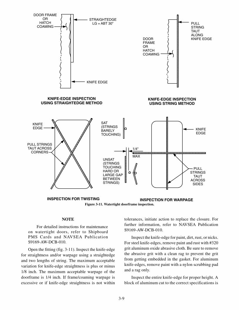
Open the fitting (fig. 3-11). Inspect the knife-edgefor straightness and/or warpage using a straightedgeand two lengths of string. The maximum acceptablevariation for knife-edge straightness is plus or minus1/8 inch. The maximum acceptable warpage of thedoorframe is 1/4 inch. If frame/coaming warpage isexcessive or if knife-edge straightness is not within
tolerances, initiate action to replace the closure. Forfurther information, refer to NAVSEA PublicationS9169-AW-DCB-010.
Inspect the knife-edge for paint, dirt, rust, or nicks.For steel knife-edges, remove paint and rust with #320grit aluminum oxide abrasive cloth. Be sure to removethe abrasive grit with a clean rag to prevent the gritfrom getting embedded in the gasket. For aluminumknife-edges, remove paint with a nylon scrubbing padand a rag only.
Inspect the entire knife-edge for proper height. Ablock of aluminum cut to the correct specifications is
3-9
DOOR FRAMEOR
HATCHCOAMING
STRAIGHTEDGELG = ABT 30"
KNIFE EDGE
KNIFE-EDGE INSPECTIONUSING STRAIGHTEDGE METHOD
KNIFE-EDGE INSPECTIONUSING STRING METHOD
INSPECTION FOR WARPAGEINSPECTION FOR TWISTING
KNIFEEDGE KNIFE
EDGE
PULL STRINGSTAUT ACROSS
CORNERS
PULLSTRINGS
TAUTACROSS
SIDES
PULLSTRINGTAUTALONGKNIFE EDGE
SAT(STRINGSBARELYTOUCHING)
UNSAT(STRINGSTOUCHINGHARD ORLARGE GAPBETWEENSTRINGS)
1/4"
MAX
DOORFRAMEORHATCHCOAMING
Figure 3-11. Watertight doorframe inspection.
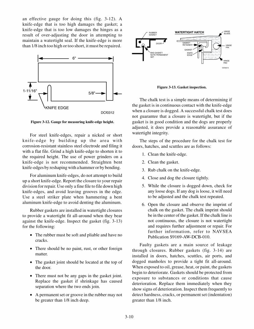
an effective gauge for doing this (fig. 3-12). Aknife-edge that is too high damages the gasket; aknife-edge that is too low damages the hinges as aresult of over-adjusting the door in attempting tomaintain a watertight seal. If the knife-edge is morethan 1/8 inch too high or too short, it must be repaired.
For steel knife-edges, repair a nicked or shortknife-edge by building up the area withcorrosion-resistant stainless steel electrode and filing itwith a flat file. Grind a high knife-edge to shorten it tothe required height. The use of power grinders on aknife-edge is not recommended. Straighten bentknife-edges by reshaping with a hammer or by bending.
For aluminum knife-edges, do not attempt to buildup a short knife-edge. Report the closure to your repairdivision for repair. Use only a fine file to file down highknife-edges, and avoid leaving grooves in the edge.Use a steel striker plate when hammering a bentaluminum knife-edge to avoid denting the aluminum.
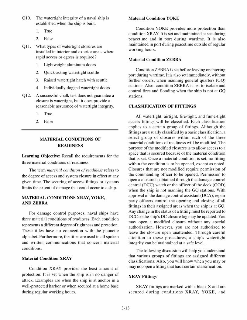
Rubber gaskets are installed in watertight closuresto provide a watertight fit all-around when they bearagainst the knife-edge. Inspect the gasket (fig. 3-13)for the following:
• The rubber must be soft and pliable and have nocracks.
• There should be no paint, rust, or other foreignmatter.
• The gasket joint should be located at the top ofthe door.
• There must not be any gaps in the gasket joint.Replace the gasket if shrinkage has causedseparation where the two ends join.
• A permanent set or groove in the rubber may notbe greater than 1/8 inch deep.
The chalk test is a simple means of determining ifthe gasket is in continuous contact with the knife-edgewhen a closure is dogged. A successful chalk test doesnot guarantee that a closure is watertight, but if thegasket is in good condition and the dogs are properlyadjusted, it does provide a reasonable assurance ofwatertight integrity.
The steps of the procedure for the chalk test fordoors, hatches, and scuttles are as follows:
1. Clean the knife-edge.
2. Clean the gasket.
3. Rub chalk on the knife-edge.
4. Close and dog the closure tightly.
5. While the closure is dogged down, check forany loose dogs. If any dog is loose, it will needto be adjusted and the chalk test repeated.
6. Open the closure and observe the imprint ofchalk on the gasket. The chalk imprint shouldbe in the center of the gasket. If the chalk line isnot continuous, the closure is not watertightand requires further adjustment or repair. Forfurther information, refer to NAVSEAPublication S9169-AW-DCB-010.
Faulty gaskets are a main source of leakagethrough closures. Rubber gaskets (fig. 3-14) areinstalled in doors, hatches, scuttles, air ports, anddogged manholes to provide a tight fit all-around.When exposed to oil, grease, heat, or paint, the gasketsbegin to deteriorate. Gaskets should be protected fromexposure to substances or conditions that causedeterioration. Replace them immediately when theyshow signs of deterioration. Inspect them frequently todetect hardness, cracks, or permanent set (indentation)greater than 1/8 inch.
3-10
KNIFE EDGE
6"
1-11/16" 5/8"
DCf0312
Figure 3-12. Gauge for measuring knife-edge height.
RUBBERGASKET
DOOR
HINGEBLADE
HINGEPIN
HINGEPAD
KNIFE-EDGE
GASKETRETAINER
GASKET
BAD GASKET:NOTE PERMANENTSET
WATERTIGHT HATCH
DCf0313
Figure 3-13. Gasket inspection.

Gaskets for bolted manhole covers and otherbolted plates differ in size, shape, and material fromthose used with doors, hatches, scuttles, and doggedmanholes. Bolted manhole covers and bolted plategaskets should be renewed whenever they are found tobe in poor condition when the cover is removed.Replacement of these gaskets at this time isparticularly important since you cannot tell anythingabout the condition of the gasket when themanhole/plate is bolted down. The gasket may appearto be perfectly all right when actually it is in a poorcondition and is providing a channel for progressiveflooding. The replacement gaskets must be of theproper material. The manhole/plate bolts must betightened up evenly all-around. A loosely securedmanhole cover can be blown off by an explosion,whereas a cover that is tightly secured will not.
Be careful when moving heavy objects, such asammunition or machinery, through watertight doorsand hatches. If you are careless, you can distort theknife-edge or bearing surface of the closure by theimpact of the heavy object.
The compression between a knife-edge and agasket should be checked periodically. If necessary,adjust the closure until the compression specified inthe manufacturer’s technical manual is reached.
Watertight doors and hatches will retain theirefficiency longer and will require less maintenance ifyou open and close them properly. When you close adoor or hatch, secure a dog that is on the OPPOSITESIDE of the closure from the hinges. Use just enoughpressure to keep the door closed. Next, secure two dogson the hinge side until snug. Then secure all theremaining dogs evenly to ensure an even compressionall-around. When loosening dogs on watertight doorsor hatches, loosen the dogs nearest the hinges first.This will keep the closure from springing and makes iteasier to operate the remaining dogs.
A common place for leakage is around dogspindles where the spindles pass through doorframes.There is a stuffing box for each dog spindle. Thepacking in the stuffing box prevents leakage. Inspectthe stuffing boxes frequently to ensure that they are ingood condition. Tighten the packing gland to give thecorrect compression of the packing. Repack the dogswhen the packing gets hard or deteriorates with age.Occasional adjustment of the dogs is required tocompensate for the wearing down of the wedges,which the dogs bear down on. When wedges becomebadly worn, you should either build them up again bygas brazing or replace them.
For a door or hatch to be watertight when it isdogged, the knife-edge or bearing surface of theclosure must be centered on the gasket. The knife-edgemust also bear down on the gasket firmly and evenlyall-around for the closure to be watertight. The doorwill not be watertight if either the door or the frame iswarped. Also, the closure will not be watertight if thedoor or hatch is not located correctly on its hinges withrespect to the doorframe. Other factors governing aclosure’s watertight feature are whether or not theknife-edge is straight and even, whether the retainerstrips are secured firmly in place, and whether the dogsare adjusted to provide equal pressure on all of thewedges when the dogs are snugly set up. If any of theseparts have an incorrect fit, the frame or knife-edgesmay come into contact with the metallic parts of theclosure and thus allow the closure to be closed in anon-watertight condition.
Some ventilation ducts have covers to isolate theventilation system. The gaskets on these covers aresubject to the same kinds of failure that access closuregaskets are. Many ventilation closures and valvesinstalled in the ventilation ducts lack tightness becauseof improper seating. These fittings should be inspectedon a regular basis. If you lubricate and maintain thefittings on a routine basis, the fittings will stay in goodworking condition indefinitely.
Throughout the ship, electric cables pass throughmany watertight boundaries. The watertight integrity ismaintained by passing each cable through a packedstuffing tube (fig. 3-15). Usually, several cables willpass through a deck or bulkhead in a small area knownas a multi-cable transit frame (fig. 3-16). The stuffingtube nearest the center of the group can be repacked onlywith a great deal of difficulty. It is vital, however, that thepacking be replaced when necessary. If you allow bad
3-11
Figure 3-14. Watertight door parts.

packing to remain in the stuffing tube, you will haveprovided a means for progressive flooding to take place.
Leakage can occur where pipes pass throughbulkheads and decks. Various methods are used tomake the penetration points watertight. Watertightpenetration points reduce the chance of progressiveflooding.
Air-port covers operate basically the same as doorsand hatches. You might need to tighten up the dogs onthe air-port covers. If the dogs are not tight, the glasslenses of the air port can be broken by heavy seas or bythe movement of the ship. When you secure an air-portcover, be sure to bring the hinge pin of the cover all theway out to the end of the hinge. By doing this, you canavoid the possibility of breaking the cover.
To replace the glass lens, drill and tap holes in theworkbench top. These holes will need to be the samesize as the holding bolts that are fitted through thesecuring lugs of the air-port frame. By drilling andtapping these holes, you will save a considerableamount of time when replacing the glass lens. Once you
secure the air-port frame to the workbench, you will beable to unscrew the retaining ring. After you remove theold glass lens, clean the threads of the frame and theretaining ring. If the frame and ring are made ofcomposition material, apply a light coating of oil orgrease to the threads. Before you insert a new glass,embed the edges of the glass in red lead putty or anotherapproved material. When you secure the retaining ring,the putty is forced out evenly all-around the glass lens,thereby ensuring a tight fit.
SAFETY
Safety is a major concern in whatever you do.When opening a closure, you can protect yourself bystanding on the opposite side from the hinges andloosening the dogs nearest the hinge first. You will thenfind it easier to loosen the other dogs, and the door willnot hurt you if there is an explosion within thecompartment. The hinges help to keep the door fromblowing open. If you are on the hinge side of the doorwhen an explosion occurs, you will be caught betweenthe door and the bulkhead.
Each closure has a safety device. Some hatches havestanchions; others have locking latches. Both devicesuse toggle pins to secure them in place. Be sure that thetoggle pins are in place at all times when the hatch isopen. Watertight scuttles have a safety device known asa bracing link assembly. Make sure that the bracing linkassembly is in good operating condition at all times.When exiting a compartment through a scuttle, do notgrab hold of the scuttle to pull yourself through. If thebracing link assembly fails to lock, the scuttle will fallon your head or fingers, causing considerable injury. Adoor catch is installed for each shipboard door. When adoor is to be left open for a period of time, use the doorcatch. The movement of the ship could cause the door toslam shut. A door slamming shut will damage the door’sgasket and could seriously injure a person. Mostpersonnel injuries are not caused by the closure’sdesign, but rather by an individual’s carelessness.
3-12
COMPRESSION BOLT
END PACKING ASSEMBLY
COMPRESSION PLATE
NEOPRENE FILL-IN
NEOPRENE INSERTBLOCKS
STAY PLATE
DECK
SPAREPLUG
MULTI-CABLETRANSIT FRAME
BULKHEADALUMINUMOR STEEL
BULKHEAD
CABLE
CABLE SUPPORT
DECKCABLE SUPPORT
DCf0316
Figure 3-16. Multi-cable transit frame.
Q9. What type of door provides access to acompartment that is not often used?
1. Lightweight aluminum door
2. Quick-acting watertight door
3. Raised watertight hatch with scuttle
4. Individually dogged watertight door
REVIEW QUESTIONS
CABLESTUFFING
TUBE
PACKING
WELD
CABLE
BULKHEAD
PACKINGGLAND
NUT
DCf0315
Figure 3-15. Cable penetration through watertight bulkhead.
MATERIAL CONDITIONS OF
READINESS
Learning Objective: Recall the requirements for the
three material conditions of readiness.
The term material condition of readiness refers tothe degree of access and system closure in effect at anygiven time. The securing of access fittings or systemslimits the extent of damage that could occur to a ship.
MATERIAL CONDITIONS XRAY, YOKE,AND ZEBRA
For damage control purposes, naval ships havethree material conditions of readiness. Each conditionrepresents a different degree of tightness and protetion.These titles have no connection with the phoneticalphabet. Furthermore, the titles are used in all spokenand written communications that concern materialconditions.
Material Condition XRAY
Condition XRAY provides the least amount ofprotection. It is set when the ship is in no danger ofattack. Examples are when the ship is at anchor in awell-protected harbor or when secured at a home baseduring regular working hours.
Material Condition YOKE
Condition YOKE provides more protection thancondition XRAY. It is set and maintained at sea duringpeacetime and in port during wartime. It is alsomaintained in port during peacetime outside of regularworking hours.
Material Condition ZEBRA
Condition ZEBRA is set before leaving or enteringport during wartime. It is also set immediately, withoutfurther orders, when manning general quarters (GQ)stations. Also, condition ZEBRA is set to isolate andcontrol fires and flooding when the ship is not at GQstations.
CLASSIFICATION OF FITTINGS
All watertight, airtight, fire-tight, and fume-tightaccess fittings will be classified. Each classificationapplies to a certain group of fittings. Although thefittings are usually classified by a basic classification, aselect group of closures within each of the threematerial conditions of readiness will be modified. Thepurpose of the modified closures is to allow access to aspace that is secured because of the material conditionthat is set. Once a material condition is set, no fittingwithin the condition is to be opened, except as noted.Closures that are not modified require permission ofthe commanding officer to be opened. Permission toopen a closure is obtained through the damage controlcentral (DCC) watch or the officer of the deck (OOD)when the ship is not manning the GQ stations. Withapproval of the damage control assistant (DCA), repairparty officers control the opening and closing of allfittings in their assigned areas when the ship is at GQ.Any change in the status of a fitting must be reported toDCC so the ship's DC closure log may be updated. Youmay open a modified closure without any specialauthorization. However, you are not authorized toleave the closure open unattended. Through carefulattention to these procedures, a ship's watertightintegrity can be maintained at a safe level.
The following discussion will help you understandthat various groups of fittings are assigned differentclassifications. Also, you will know when you may ormay not open a fitting that has a certain classification.
XRAY Fittings
XRAY fittings are marked with a black X and aresecured during conditions XRAY, YOKE, and
3-13
Q10. The watertight integrity of a naval ship isestablished when the ship is built.
1. True
2. False
Q11. What types of watertight closures areinstalled in interior and exterior areas whererapid access or egress is required?
1. Lightweight aluminum doors
2. Quick-acting watertight scuttle
3. Raised watertight hatch with scuttle
4. Individually dogged watertight doors
Q12. A successful chalk test does not guarantee aclosure is watertight, but it does provide areasonable assurance of watertight integrity.
1. True
2. False

ZEBRA. Ship personnel must have special authorizationto open these fittings. The black X identifying an XRAYclassification should be on the following closures:
• Doors and hatches to storerooms and stowagespaces, including cargo ammunition spaces
• Hatches that are provided with a scuttle and lead tomagazines and handling rooms
• Bolted-plate manhole covers
• Escape scuttles not covered elsewhere
• Doors and hatches located only on the weatherdeck and below that are used to strike down storesand ammunition
• Access to an aircraft fueling station compartment
• Access to escape trunks in machinery spaces
• Access to the arresting gear machinery room
• Access to the eductor room
• Access to the capstan and winch control room
• Access to the chain locker
• Access to the stores elevator
• Access to the catapult machinery room
• Access to forced draft blower rooms
• Access to fan rooms
CIRCLE XRAY fittings are marked with a black Xinside of a black circle. These modified closures aresecured during conditions XRAY, YOKE, and ZEBRA.However, personnel may open these fittings withoutspecial authorization when proceeding to battle stationsor as required in routine inspection checks. You mayopen these closures, but you must secure themimmediately after use.
CIRCLE XRAY closures and fittings are markedwith a black X inside of a black circle. These closuresand fittings are as follows:
• Doors to magazines and handling rooms
• Hatches that do not have a scuttle and lead tomagazines and handling rooms
• Access to the missile handling and check-out areacompartments
• Scuttles in hatches to the shaft alley, pump rooms,magazines, and handling rooms
• Access to the gas and fuel station and filter rooms
• Access to the oxygen-nitrogen rooms(compressor and producing)
• Access to the switch gear room, ammunitionhoist, and elevators
• Access to the underwater log room
• Access to the equipment rooms that areunoccupied
• Scuttles for passing ammunition
YOKE Fittings
YOKE fittings are marked with a black Y and aresecured during conditions YOKE and ZEBRA. Youmust have proper authorization to open fittings withthis classification when the ship is at conditionYOKE or ZEBRA.
YOKE closures and fittings marked with a blackY are as follows:
• Hatches that are provided with a scuttle andlead to shaft alleys and pump rooms
• Alternate accesses to machinery rooms
• Weather deck hatches not classified as XRAY
• Some alternate accesses on the DC deck andabove
• Access to the windlass room
• Access to the generator rooms
• Access to the air compressor room
• Access to the air-conditioning machineryroom
• Access to the refrigeration machinery room
• Access to the elevator machinery room
• Access to the missile director machinery room
• Access to the drying room
CIRCLE YOKE fittings are marked with a blackY inside of a black circle. These modified fittings aresecured during conditions YOKE and ZEBRA.However, these fittings may also be opened withoutspecial authorization when personnel are proceedingto battle stations or as required in routine inspectionchecks. Again, you must secure these closuresimmediately after use.
CIRCLE YOKE fittings and closures markedwith a black Y inside of a black circle are as follows:
3-14

• Hatches that do not have a scuttle and lead to theshaft alley and pump room
• Scuttles in the deck to the shaft alley and pumproom
• Doors at the bottom of the trunk to the shaft alleyand pump room
• Access to the steering gear power and ram room
• Access to the chill room
ZEBRA Fittings
ZEBRA fittings are marked with a red Z, and theseclosures are secured during condition ZEBRA. Youmust have proper authorization to open fittings with thisclassification when the ship is at condition ZEBRA.
ZEBRA closures and fittings marked with a red Zare as follows:
• All remaining doors and hatches for routineaccess
• Access to all shops, labs, commissary, utility,control, and hospital spaces
• Access to all offices
• Access to equipment rooms occupied whenassociated control room is in use
• Main access to machinery spaces
• Access to issue rooms
• Access to the steering gear room
• Access to the enclosed operating stations
• Access to hangar and flight deck control stations
• Access to the garbage disposal room
• Access to the trash burner and bin room
CIRCLE ZEBRA fittings are marked with a red Zinside a red circle. These modified fittings are securedduring condition ZEBRA. CIRCLE ZEBRA fittingsmay be opened with the commanding officer'spermission during prolonged periods of GQ. Theopening of these fittings allows evolutions such as thepreparation and distribution of battle rations, opening oflimited sanitary facilities, ventilation of battle stations,and access for aviation personnel to the flight deck.When open, CIRCLE ZEBRA fittings must be guardedso they may be closed immediately if necessary.
CIRCLE ZEBRA closures and fittings markedwith a red Z inside a red circle are as follows:
• Limited doors or scuttles from the weather deckto the crew's galley
• Doors from aviators and flight crew ready roomsto the flight deck
DOG ZEBRA fittings are marked with a red Zinside a black D. These modified fittings are securedduring condition ZEBRA and darken ship conditions.You must have proper authorization to open fittingswith this classification when the ship is at eithercondition ZEBRA or darken ship.
DOG ZEBRA fittings marked with a red Z inside ablack D are as follows:
• Doors to the weather deck, excluding thoseclassified XRAY or YOKE, that do not have adarken ship switch or a darken ship curtain
• Air ports (portholes)
WILLIAM Fittings
WILLIAM fittings are marked with a black W.These fittings are kept open during all materialconditions. WILLIAM fittings are secured only asnecessary to control damage or CBR contaminationand to make repairs to the equipment served.
WILLIAM fittings are marked with a black W areas follows:
• Vital sea suction valves that supply the main andauxiliary condensers, fire pumps, and spaces thatare manned during conditions XRAY, YOKE,and ZEBRA
• Vital valves that if secured would impair themobility and fire protection of the ship
CIRCLE WILLIAM fittings are marked with ablack W inside a black circle. These fittings arenormally kept open, as is the case with WILLIAMfittings. They must, however, be secured to prevent thespread of damage and as a defense measure when aCBR attack is imminent.
CIRCLE WILLIAM fittings are marked with ablack W inside a black circle are as follows:
• Doors to the pilot house, flag bridge, and signalshelter
• Ventilation systems to main and auxiliarymachinery spaces, generator spaces, and othersystems and fittings serving spaces incontinuous use
3-15

If access to a space is through a series of hatchesand/or scuttles, all of the closures that provide thataccess must bear the same classification as that of thespace. For example, a pump room is classified asCIRCLE YOKE. This means it is open duringcondition XRAY and closed during condition YOKE.All hatches, scuttles, and/or doors that provide accessto the pump room must also be classified CIRCLEYOKE to allow routine access to the pump room.
When a fan room door must be kept open to supplyair to a fan or to exhaust air from it, the door should havethe same classification as that of the fan. For example, a
fan room containing a YOKE fan has a YOKE door; aroom containing YOKE and ZEBRA fans has a ZEBRAdoor. All other fan room doors are classified XRAY.
A classification has no bearing on the security of aspace. A space classified ZEBRA may, for securityreasons, be locked during condition YOKE if the spaceis unattended. However, the locking must be reportedto the DCA or to the OOD.
Table 3-2 contains additional information ondamage control closures and their classifications.
3-16
SYSTEM ORFITTING
XRAY YOKE ZEBRA WILLIAM
Air escapes Damage control voids notcontaining pressure piping.
Damage control voidscontaining pressurepiping.
Air ports All lens frames. Dog Zebra:
Metal covers.
Air test fittings All.
Aviation fuel systems(gasoline and JP-5)
All valves.
Compressed air Valves to counter recoil charging to gunmounts,torpedo charging valves,cutout valves to othersystems not serving Wfittings, elevator pressuretanks, catapult machinery,diesel engine air startingtank and test sets; controlvalve at compressor tomain; hose outlets;compartment testing valves.
All other valves.
Damage controlballast valves
All.
Drainage All valves in main andsecondary drainagesystems; bilge suctionand overboard dischargevalves in machineryspaces; miscellaneousdrainage valves; portablesubmersible pumpoverboard dischargeconnections.
All deck drainvalves, plug cocks,valves, scuppers,and vent valves forplumbing drains;gravity overboarddischarge valvesfrom unit coolersand air conditioningunits.
Deck drains and flapvalves fromoperating room.
Table 3-2. Damage Control Classifications

3-17
SYSTEM ORFITTING
XRAY YOKE ZEBRA WILLIAM
Firemain, flushing, andsprinkling systems
Valves not segregatinginto sections and notadversely affectingpressure in main risers;valves actuating mainand bilge drainageeductors; sea suctionvalve in pump room;sprinkling group controlvalves; washdownsystem hose valves;submersible pumppriming valves; fog foamvalves; hangar sprinklingvalves; water curtainvalves and caps; caps forfixed fog systems.(NOTE: In casefiremain and drainagevalves are interlocked,firemain valve is X anddrainage valve isunclassified.)
Valves for segregationof firemain into portand starboardlongitudinal sections,where practicable, andwith two or morepumps supplying eachsection.
Valves for segregationof firemain into four ormore sections; firemainvalves to flushingsystem. Valvesactuating drainageeductors from quarters;certain cooling watersystem valves.
All other firemainvalves; valves tocooling water systemsfor vital machinery;sprinkling valvescontrolled by groupvalves; sea suctionvalves for fire pumpsin machinery spacesand overboarddischarge fromgasoline tank.
Fresh water Filling connectionvalves.
Root valves abovemachinery spaces.
Drinking fountains formachinery spaces; gunbarrel and rocketlaunches coolingsystems; all othervalves unclassified.
Oil and ballast systems(fuel and JP-5 filling,transfer, and overflowsystems)
All valves, exceptinterlocking valves andthose in way of pump,which shall beunclassified.
Sounding tube deckplates and valves forvoids, oil and watertanks
All.
Table 3-2. Damage Control Classifications (Continued)
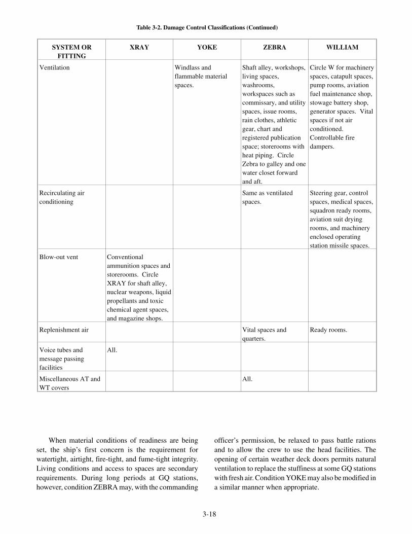
When material conditions of readiness are beingset, the ship’s first concern is the requirement forwatertight, airtight, fire-tight, and fume-tight integrity.Living conditions and access to spaces are secondaryrequirements. During long periods at GQ stations,however, condition ZEBRA may, with the commanding
officer’s permission, be relaxed to pass battle rationsand to allow the crew to use the head facilities. Theopening of certain weather deck doors permits naturalventilation to replace the stuffiness at some GQ stationswith fresh air. Condition YOKE may also be modified ina similar manner when appropriate.
3-18
SYSTEM ORFITTING
XRAY YOKE ZEBRA WILLIAM
Ventilation Windlass andflammable materialspaces.
Shaft alley, workshops,living spaces,washrooms,workspaces such ascommissary, and utilityspaces, issue rooms,rain clothes, athleticgear, chart andregistered publicationspace; storerooms withheat piping. CircleZebra to galley and onewater closet forwardand aft.
Circle W for machineryspaces, catapult spaces,pump rooms, aviationfuel maintenance shop,stowage battery shop,generator spaces. Vitalspaces if not airconditioned.Controllable firedampers.
Recirculating airconditioning
Same as ventilatedspaces.
Steering gear, controlspaces, medical spaces,squadron ready rooms,aviation suit dryingrooms, and machineryenclosed operatingstation missile spaces.
Blow-out vent Conventionalammunition spaces andstorerooms. CircleXRAY for shaft alley,nuclear weapons, liquidpropellants and toxicchemical agent spaces,and magazine shops.
Replenishment air Vital spaces andquarters.
Ready rooms.
Voice tubes andmessage passingfacilities
All.
Miscellaneous AT andWT covers
All.
Table 3-2. Damage Control Classifications (Continued)

COMPARTMENT CHECKOFF LISTS
Learning Objective: Recall the purpose of the
compartment checkoff list (CCOL) and the type of
information listed on it.
CCOLs (fig. 3-17) provide an itemized listingof all classified fittings and closures used in damagecontrol to set the specified material condition ofreadiness. They are originally prepared andfurnished by the ship builder’s design agent duringthe construction of a ship or class of ships. After thatit is each ship’s responsibility to keep the listscurrent. Follow the guidelines listed in the NavalShips’ Technical Manual (NSTM), chapter 079,volume 2, when you check and update your CCOLs.
Al l compar tments must have a CCOLpermanently posted within them in clear view of thespace access. Weather deck areas that have damagecontrol facilities must also have a CCOL posted. Thecompartment name and number are entered on thelist along with all classified fittings and certain otherdamage control facilities in the compartment that arenecessary to help damage control personnel in theperformance of their duties. The information listedfor each of the classified fittings includes thefollowing:
• Name of item
• Number of item
• Location of item
• Purpose of item
• Classification of item (if classified)
• Division responsible for the proper operationof each fitting
When a compartment has more than oneentrance, duplicate CCOL must be posted at eachentrance. The CCOLs shall be clearly labeledDUPLICATE. Partial CCOLs may be desirable whenthere are alcoves or areas included within acompartment. The partial CCOL list shall be clearlylabeled PARTIAL. The item numbers on the partiallist must correspond with the numbers on the originallist.
CCOLs for the weather decks, and some otherdecks, may be divided by sections; for example, maindeck, frame 90-120, port side. The DCA maintains amaster copy of each original and partial CCOL onfile in DCC. The division officer is responsible forinforming the DCA when a change is required and
3-19
Q13. What material condition of readiness providesthe least amount of protection?
1. ZULU
2. ZEBRA
3. YOKE
4. XRAY
Q14. The three material conditions of readiness areXRAY, YOKE, and ZEBRA.
1. True
2. False
Q15. What material condition is set to isolate andcontrol fires and flooding when the ship is notat general quarters station?
1. ZULU
2. ZEBRA
3. YOKE
4. XRAY
Q16. Fittings having what classification are keptopen during all material conditions?
1. CIRCLE XRAY
2. DOG ZEBRA
3. CIRCLE YOKE
4. WILLIAM
Q17. What classification of fitting may be openedwithout special authorization when proceedingto battle stations or as required in routineinspection checks?
1. CIRCLE ZULU
2. CIRCLE ZEBRA
3. CIRCLE XRAY
4. CIRCLE YOKE
REVIEW QUESTIONS

3-20
Figure 3-17. Compartment checkoff list.

use of CCOL software is required as available per therequirements of NSTM, chapter 079, chapter 2.
Other responsibilities assigned ship personnel areas follows:
• Division officers are responsible for maintainingthe list in good physical condition.
• The commanding officer, assisted by the DCA,is responsible for filling in the column markedDIVISION RESPONSIBILITY.
• The divisions concerned are responsible forsecuring fittings that are classified as XRAY orYOKE.
• The ship’s repair parties are responsible forsecuring ZEBRA fittings.
DAMAGE CONTROL CLOSURE LOG
Learning Objective: Recall the purpose of the damagecontrol closure log and how to use it correctly.
All ships are required to prepare and maintain adamage control closure log (fig. 3-18). To completeyour General Damage Control PQS, you are required toknow what the damage control closure log is and how touse it correctly. Strict discipline must be maintained inthe modification of a material condition of readiness. Asmentioned before, you must obtain permission beforeyou change a material condition setting in any way.Obtain the permission from the DCA or the OOD.During GQ, repair party officers control the opening andclosing of all fittings in their assigned areas. The repairparty officers must keep DCC informed so the ship’sdamage control closure log can be kept up-to-date.
The closure log is maintained at all times, whetherthe ship is in port or underway. The closure log is usedto show the following:
• Where the existing material condition ofreadiness has been modified.
• The fitting’s type, number, and classification.
• The name, rate, and division of the person whorequested permission to open or close the fitting.
• The date and time the fitting was opened orclosed.
• The date and time the fitting was returned to itsspecified material condition of readiness setting.
• The name and rate/rank of the person grantingpermission.
3-21
Q18. All compartments must have a CCOLpermanently posted within them in clearview of the space access.
1. True
2. False
Q19. When a compartment has more than oneentrance, duplicate CCOLs must be postedat each entrance.
1. True
2. False
REVIEW QUESTIONS
D.C. CLOSURE LOG
IN ACCORDANCE WITH OPNAVINST 3120.32PERSON REQUESTING
PERMISSION
IDENTIFICATION OF FITTING OPENED CLOSED PERSONGRANTING
PERMISSION
NAME RATE DIV TYPE CLASSIFI-CATION
NUMBER DATE TIME DATE TIME ESTTIMEOPEN
NAME RANKOR
RATE
Trulson DC2 R WTH X 4-75-1 06/02/01 24 hrs. JamesWatson
DC1
Figure 3-18. Damage Control Closure Log record sheet.

The commanding officer prescribes the limit towhich the DCA or OOD may approve the modificationof a material condition of readiness. Reporting thetemporary closing of a fitting that should be open is justas important as reporting the opening of one thatshould be closed. For example, a ZEBRA watertighthatch that is secured at the time GQ is sounded couldseriously interfere with personnel trying to get to theirbattle stations.
The damage control closure log is normally kepton the quarterdeck in port, on the bridge at sea, and inDCC during GQ. However, if your ship has a 24-hourwatch in DCC at all times, the closure log will be keptthere no matter where the ship is. The closure log isupdated when there is a change in the status of aclassified closure or fitting. If a classified closure is toremain open for several days, it must be logged openeach day. The maximum time a closure or fitting maybe logged open is 24 hours.
You must keep all closures and fittings in the bestpossible condition at all times to maintain the ship’swatertight integrity feature. Neglected closures andfittings could lead to the loss of your ship.
METHODS OF CHECKINGWATERTIGHT INTEGRITY
Learning Objective: Recall the procedures forchecking watertight integrity.
Watertight integrity features are built into navalships. There must be regular inspections conducted onthe ship and its watertight integrity features. The ship’sPlanned Maintenance System (PMS) gives specificdetails for conducting the compartment tests andinspections. The Naval Ships’ Technical Manual(NSTM), chapter 079, volume 4, also covers variouscompartment tests and inspections. The ship’sschedule of watertight integrity tests and inspections ismaintained in the ship’s damage control library. Referto the above references when you schedule andconduct the required tests and inspections.
VISUAL INSPECTION
Often you can discover holes or cracks inwatertight bulkheads and decks by conducting athorough visual inspection. If a compartment containsoil, water, or some other liquid, any leakage will beevident. Other sources for leakage include loose rivetheads, poorly caulked plate laps or stiffeners, andpoorly caulked bounding angles. All leaks should berepaired as soon as possible to re-establish the ship’swatertight integrity. If the repairs are beyond thecapability of the ship’s force repair personnel, the workshould be included in the work package for the nextshipyard, tender, or repair ship availability.
You will, at specified intervals, conduct a visualinspection for light leaks within most compartments onthe ship. To make this inspection, completely close offthe compartment and secure all lighting within thecompartment. Have another person (an observer) stayinside the darkened compartment to look for lightleaks. Then you will need to ensure that lighting is onin the surrounding spaces. As a rule, the light from thesurrounding compartments will allow the observer tolocate any serious defects. However, you might need touse portable lights to provide a higher level ofillumination in some areas. The observer will also needa portable light to transit the darkened space safely.
COMPARTMENT AIR TEST
The ship’s schedule of watertight integrity testsand inspections is issued by NAVSEA for each ship.This schedule contains information on each watertightcompartment and the type of test used to determine thecompartment’s tightness. Compartments designatedfor air testing are scheduled so all are tested once every18 months for ships at least 12 years old. For ships thatare less than 12 years old, the compartments are testedonce every 36 months. Compartments that are
3-22
Q20. What person prescribes the limit to which theDCA or OOD may approve the modificationof a material condition of readiness?
1. Executive officer
2. Damage control supervisor
3. Damage control assistant
4. Commanding officer
Q21. The closure log is maintained at all times,whether the ship is in port or underway.
1. True
2. False
Q22. The maximum time a closure or fitting maybe logged open is 24 hours.
1. True
2. False
REVIEW QUESTIONS

designated for air testing are provided with fittings forattaching the air test set. In the case of tanks, you mayuse sounding tubes or air escapes to connect the air testset. Figure 3-19 shows the air test set that is providedfor shipboard use. The manufacturer’s technicalmanual, provided with each set, gives detailedinstructions for operating the air test set.
The information contained in the ship’s scheduleof watertight integrity tests and inspections must bestrictly adhered to when conducting compartment airtests. The air test pressure listed in the schedule mustNEVER be exceeded. You can seriously damage thestructures and boundaries of the compartment beingtested if the recommended pressure is exceeded.
Before starting an air test, you need to conduct avisual inspection of the compartment and repair all theleaks that you find. Notify the engineer officer, theDCA, and the OOD of your intent to conduct acompartment air test and which compartments will beinvolved. Also, have an Electrician’s Mate (EM) assistin de-energizing the electrical push-button alarms andremote-controlled valves for sprinkling, flooding, orcounterflooding systems if any are installed in thecompartment to be tested. These devices havediaphragm covers and would be activated when the airtest pressure is admitted to the compartment unlessthey had been previously de-energized.
All fittings that serve the compartment must besecured or blanked off before the air test is conducted.If any rotating shafts or other moving parts penetrate
the bulkheads, you must tighten the packing beforeconducting the air test to maintain the air pressure.
Make sure that the crew is aware of thecompartment air test being conducted. Post signs atevery possible access to the compartment(s) beingtested. If an observer is stationed inside thecompartment during the compartment air test, eachaccess to the compartment must have someone postedat the access closure. The guards are to prevent theaccess closure from being opened until the excessivepressure within the compartment is relieved. The airtest pressure used in a compartment air test is relativelylow. However, a dangerous total force can bedeveloped on quick-acting doors and hatches.Personnel should be instructed not to attempt to openquick-acting doors or hatches when a compartment isunder air test. A person opening these doors or hatcheswhile the compartment is under pressure could likelysustain severe injuries.
When conducting a compartment air test on a largecompartment, use as many personnel as required tocheck for leaks. The personnel involved with the testneed to maintain communication with each other. TheX40J (salt and pepper or international orange) rig canbe used, allowing you to have an isolated circuitwithout interruptions. When you are conducting acompartment air test, any loss of pressure in excess ofthe allowable drop listed in the schedule over thespecified period of time indicates deterioration of thewatertight integrity of the compartment. If correctivemeasures are beyond the capacity of ship’s force, thecompartment must be listed as UNSATISFACTORY.You must then request that repairs be completed duringthe next availability.
While the compartment is under test, leaks will bedisclosed by hissing or whistling noises as the airescapes. All leaks should be located, marked, andlisted for corrective action. You should repair all leaksthat were found and then test the compartment again. Ifthe allowable pressure drop is again exceeded on thistest, apply a soap solution to the boundaries of thecompartment and to all joints, fittings, and closures.When the air pressure is applied, bubbles will beformed by escaping air, thus indicating the location ofthe leaks.
The observer inside the compartment will have alighted candle. As the observer goes over areas whereleaks are suspected, the deflection of the flame willindicate the location of leaks.
3-23
INSTRUCTIONMANUAL
STORAGE BOX
AIR TEST SET
SENSING LINE PROBE
EXTENSION LEGS
PIPE TO HOSE ADAPTERSSENSING LINE
EXTENSION
CHARGE LINEEXTENSION
HOSE
DCf0317
Figure 3-19. Air test set.

Upon completion of the compartment air test,relieve the air pressure in the compartment. Be surethat all caps for the air test fittings are replaced. Thesecaps are classified XRAY. Ensure that all temporaryclosures are removed from overflows, air escapes, andair vents in magazines and fuel oil tanks. Theboundaries are sure to be ruptured when the space isfilled or flooded if these vents and escapes are leftclosed. Then make the appropriate entries in thewatertight integrity log if your ship has one.
VENTILATION
Ventilation onboard ship provides comfort for thecrew in their work area or berthing space. It is also usedto keep electronic spaces cool. Ventilation is used tocirculate air throughout the ship, and to maintaindifferent climates and comfort zones in various areas.Quite obviously the air circulating through the ship’schillbox is maintained at a different temperature andhumidity than the climate in berthing areas. Manyareas of the ship contain sensitive electronicequipment that will fail if not kept properly cooled.Just as obviously, you and your shipmates cannotperform your jobs efficiently if your work environmentis uncomfortable.
A variety of ventilation heaters and pre-heaters areused to warm the air coming into the ship, andair-conditioning systems and coolers are used to coolthe air where necessary. Ventilation ducting anddampers are used to route the airflow where needed.Thermostats are used to monitor and maintain theappropriate temperatures. Air filters are used to filterparticles such as dust from the air to keep air cleaner. Itmay be necessary for you to clean, inspect, lubricate, orrepair or replace components of this vital system at anygiven time.
SUMMARY
In this chapter, you were introduced to shipcompartmentation, material conditions of readiness,the CCOL, and the damage control closure log, alongwith the relationship of each to watertight integrity. Asa Damage Controlman, you will use the informationlearned in this chapter in the daily performance of yourduties. You need to have a good understanding of eachtopic that has been discussed. If you did not understandany of these topics, go back and review them beforeyou move on to the next chapter.
3-24
Q23. When conducting a compartment test andinspection, you should follow the specificdetails provided in which of the followingreferences?
1. Ship’s watertight test instructions
2. Ship’s damage control book
3. Planned Maintenance System (PMS)
4. NSTM, chapter 79, volume 1
Q24. The ship’s schedule of watertight integritytests and inspections is issued by NAVSEA.
1. True
2. False
Q25. The information contained in the ship’sschedule of watertight integrity tests andinspections must be strictly adhered to whenyou are conducting compartment air tests.
1. True
2. False
REVIEW QUESTIONS

REVIEW ANSWERS
A1. The keel is the backbone of the ship. (1) True
A2. What is the forward edge of the stem called?(4) Cutwater
A3. The vertical distance from the keel to thewaterline of a ship is known by what term?(1) Draft
A4. The first level above the main deck is calledthe 02 level. (2) False. The first level abovethe main deck is called the 01 level.
A5. Compartmentation is the design factor on aship that allows for more effective control offires and floods. (1) True
A6. Each compartment has a four-part numberseparated by hyphens. (1) True
A7. Compartments completely to starboard aregiven odd numbers. (1) True
A8. The last part of the compartment number isthe letter that identifies the (1) primary useof the compartment
A9. What type of door provides access to acompartment that is not often used?(4) Individually dogged watertight door
A10. The watertight integrity of a naval ship isestablished when the ship is built. (1) True
A11. What types of watertight closures are installedin interior and exterior areas where rapidaccess or egress is required? (3) Raisedwatertight hatch with scuttle
A12. A successful chalk test does not guarantee aclosure is watertight, but it does provide areasonable assurance of watertight integrity.(1) True
A13. What material condition of readiness providesthe least amount of protection? (4) XRAY
A14. The three material conditions of readiness areXRAY, YOKE, and ZEBRA. (1) True
A15. What material condition is set to isolate andcontrol fires and flooding when the ship is notat general quarters stations? (2) ZEBRA
A16. Fittings having what classification are keptopen during all material conditions?(4) WILLIAM
A17. What classification of fitting may be openedwithout special authorization whenproceeding to battle stations or as required inroutine inspection checks? (3) CIRCLEXRAY
A18. All compartments must have a compartmentcheckoff list permanently posted within themin clear view of the space access. (1) True
A19. When a compartment has more than oneentrance, duplicate compartment checkofflists must be posted at each entrance. (1) True
A20. What person prescribes the limit to which theDCA or OOD may approve the modificationof a material condition of readiness?(4) Commanding officer
A21. The closure log is maintained at all times,whether the ship is in port or underway.(1) True
A22. The maximum time a closure or fitting maybe logged open is 24 hours. (1) True
A23. When conducting a compartment test andinspection, you should follow the specificdetails provided in which of the followingreferences? (3) Planned MaintenanceSystem (PMS)
A24. The ship’s schedule of watertight integritytests and inspections is issued by NAVSEA.(1) True
A25. The information contained in the ship’sschedule of watertight integrity tests andinspections must be strictly adhered to whenyou are conducting compartment air tests.(1) True
3-25
