chapter 4: implementing high availability and redundancy
TRANSCRIPT

Ali Aydemir
Chapter 4:
Implementing High Availability and Redundancy in a Campus Network
CCNP-RS SWITCH

2Ali AydemirCCNP-RS SWITCH v2.0 Chapter 4
Chapter 4 Objectives
Understand high availability.
Implement high availability.
Describe high availability monitoring options.
Describe switch supervisor redundancy.
Describe gateway redundancy protocols.
Configure and verity Cisco IOS server load balancing.

3Ali AydemirCCNP-RS SWITCH v2.0 Chapter 4
Understanding High Availability

4Ali AydemirCCNP-RS SWITCH v2.0 Chapter 4
Components of High Availability
Redundancy
Technology (including hardware and software features)
People
Processes
Tools
5Ali AydemirCCNP-RS SWITCH v2.0 Chapter 4
Redundancy
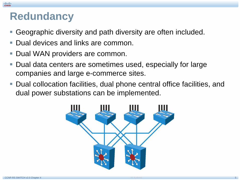
Geographic diversity and path diversity are often included.
Dual devices and links are common.
Dual WAN providers are common.
Dual data centers are sometimes used, especially for large
companies and large e-commerce sites.
Dual collocation facilities, dual phone central office facilities, and
dual power substations can be implemented.

6Ali AydemirCCNP-RS SWITCH v2.0 Chapter 4
Technology
Cisco Nonstop Forwarding
(NSF)
Stateful Switchover (SSO)
Graceful Restart
Cisco IOS IP Service Level
Agreements (SLA)
Object Tracking
Firewall Stateful Failover

7Ali AydemirCCNP-RS SWITCH v2.0 Chapter 4
People
Prepare, Plan, Design, Implement, Operate, and Optimize
(PPDIOO) is a guide.
Work habits and attention to detail important.
Skills are acquired via ongoing technical training.
Good communication and documentation critical.
Use lab testing to simulate failover scenarios.
Take time to design.
Identify roles.
Identify responsibilities.
Align teams with services.
Ensure time to do job.

8Ali AydemirCCNP-RS SWITCH v2.0 Chapter 4
Processes
Organizations should build repeatable processes.
Organizations should use labs appropriately.
Organizations need meaningful change controls.
Management of operational changes is important.

9Ali AydemirCCNP-RS SWITCH v2.0 Chapter 4
Tools
Network diagrams.
Documentation of network
design evolution.
Key addresses, VLANs,
and servers documented.
Documentation tying
services to applications
and physical servers.

10Ali AydemirCCNP-RS SWITCH v2.0 Chapter 4
Resiliency for High Availability
Network-Level Resiliency
High Availability and
Failover Times

11Ali AydemirCCNP-RS SWITCH v2.0 Chapter 4
Network-Level Resiliency
Built with device and link redundancy.
Employs fast convergence.
Relies on monitoring with NTP, SNMP, Syslog, and IP SLA.

12Ali AydemirCCNP-RS SWITCH v2.0 Chapter 4
High Availability and Failover Times
Tuned routing protocols failover in less than 1 second.
RSTP converges in about 1 second.
EtherChannel can failover in approximately 1 second.
HSRP timers are 3 seconds for hello and 10 seconds for hold time.
Stateful service modules typically failover within 3-5 seconds.
TCP/IP stacks have up to a 9-second tolerance.

13Ali AydemirCCNP-RS SWITCH v2.0 Chapter 4
Optimal Redundancy
Provide alternate paths.
Avoid too much
redundancy.
Avoid single point of
failure.
Use Cisco NSF with SSO,
if applicable.
Use Cisco NSF with
routing protocols.

14Ali AydemirCCNP-RS SWITCH v2.0 Chapter 4
Provide Alternate Paths
Use redundant distribution-
to-core links in case a core
switch fails.
Link distribution switches
to support summarization
of routing information from
the distribution to the core.

15Ali AydemirCCNP-RS SWITCH v2.0 Chapter 4
Avoid Too Much Redundancy
Where should the root switch be placed? With this design, it
is not easy to determine where the root switch is located.
What links should be in a blocking state? It is hard to
determine how many ports will be in a blocking state.
What are the implications of STP and RSTP convergence?
The network convergence is definitely not deterministic.
When something goes wrong, how do you find the source of
the problem? The design is much harder to troubleshoot.

16Ali AydemirCCNP-RS SWITCH v2.0 Chapter 4
Avoid Single Point of Failure
Key element of high availability.
Easy to implement at core and distribution.
Access layer switch is single point of failure. Reduce
outages to 1 to 3 seconds in the access layer with:
• SSO in L2 environment
• Cisco NSF with SSO in L3 environment.

17Ali AydemirCCNP-RS SWITCH v2.0 Chapter 4
Cisco NSF with SSO
Supervisor redundancy mechanism in Cisco IOS enabling
supervisor switchover at L2-L3-L4.
SSO enables standby RP to take control after fault on active
RP.
Cisco NSF is L3 function that works with SSO to minimize
time network unavailable following switchover, continuing to
forward IP packets following RP switchover.

18Ali AydemirCCNP-RS SWITCH v2.0 Chapter 4
Routing Protocols and NSF
NSF enables continued
forwarding of packets
along known routes while
routing protocol
information is being
restored during switchover.
Switchover must complete
before NSF dead and hold
timers expire or routing
peers will reset
adjacencies and reroute
traffic.

19Ali AydemirCCNP-RS SWITCH v2.0 Chapter 4
Implementing High Availability

20Ali AydemirCCNP-RS SWITCH v2.0 Chapter 4
Distributed VLANs on Access Switches
Use Rapid STP (RSTP) as the version of STP.
Provide a Layer 2 trunk between the two distribution switches to avoid
unexpected traffic paths and multiple convergence events.
Place the Hot Standby Router Protocol (HSRP) primary and the STP
primary root on the same distribution layer switch if you choose to load
balance VLANs across uplinks.
The HSRP and RSTP root should be colocated on the same distribution
switches to avoid using the interdistribution link for transit.

21Ali AydemirCCNP-RS SWITCH v2.0 Chapter 4
Local VLANs on Access Switches
No VLANs span between access layer switches across
distribution switches.
Here a single voice VLAN and a single data VLAN are
restricted to a single access switch.
Root for each VLAN aligned with active HSRP instance.
Distribution-to-distribution L3 link required for route
summarization in this design.

22Ali AydemirCCNP-RS SWITCH v2.0 Chapter 4
Layer 3 Access to the Distribution Interconnection
L3 or routed links connect distribution and access layer
switches in this design – in the future this will be the
standard (even the links to the end stations will be L3 in the
future as prices of RPs continue to decline).
Recommended practice is to map the L2 VLAN number to
the L3 subnet for ease of use and management.

23Ali AydemirCCNP-RS SWITCH v2.0 Chapter 4
Daisy Chaining Access Layer Switches (1)
No links block from an STP perspective.
Both uplinks are available to send and receive traffic.
If a link or node in the middle of the chain or stack fails, standby HSRP
peer (Dist-B) can go active as it loses connectivity to its primary peer
(Dist-A).

24Ali AydemirCCNP-RS SWITCH v2.0 Chapter 4
Daisy Chaining Access Layer Switches (2)
Here the core switch sees both distribution switches advertise the VLAN
2 subnet, doing equal cost load balancing for traffic destined to VLAN 2
between Dist-A and Dist-B.
50% chance that return traffic arrives on distribution switch that does not
have connectivity to half of stack where traffic destined. Solution: add A-
a to A-c connection.

25Ali AydemirCCNP-RS SWITCH v2.0 Chapter 4
StackWise Access Switches
Supports recommended practice of using L3 connection
between distribution switches without having to use
loopback cable or perform extra configuration.
Uses Cisco Catalyst 3750 switches in the access layer.
Much less complex than chains or stacks of other models.
Appears as one node from network topology perspective.

26Ali AydemirCCNP-RS SWITCH v2.0 Chapter 4
Too Little Redundancy (1)
VLANs span multiple access layer switches.
No L2 link between distribution switches.
Design is looped in figure-8 topology.
Once access layer uplink is blocking
HSRP hellos exchanged by transiting access switches.

27Ali AydemirCCNP-RS SWITCH v2.0 Chapter 4
Too Little Redundancy (2)
When uplink from Access A to Distribution A fails, there are
3 convergence events.

28Ali AydemirCCNP-RS SWITCH v2.0 Chapter 4
Implementing IP Service Level Agreement

29Ali AydemirCCNP-RS SWITCH v2.0 Chapter 4
IP Service Level Agreement
Contract between service provider and customers.
Specifies connectivity and performance agreements.
Includes guaranteed level of network availability, network
performance in terms of round-trip time, and network
response in terms of latency, jitter, and packet loss.
30Ali AydemirCCNP-RS SWITCH v2.0 Chapter 4
IP SLA Measurements
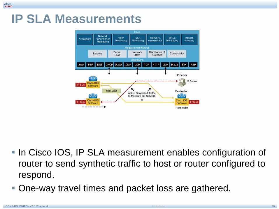
In Cisco IOS, IP SLA measurement enables configuration of
router to send synthetic traffic to host or router configured to
respond.
One-way travel times and packet loss are gathered.

31Ali AydemirCCNP-RS SWITCH v2.0 Chapter 4
IP SLA Operations
Network engineer configures a target device, protocol, and UDP or TCP
port number on the IP SLA source for each operation. Source uses IP SLA
control protocol to communicate with responder before sending test
packets.
To increase security on IP SLA measurements control messages,
responder can utilize MD5 authentication for securing the control protocol
exchange.
When operation finished and response received, results are stored in IP
SLA MIB on source and retrieved using SNMP.
IP SLA operations are defined by target devices. If operation is something
such as DNS or HTTP, target device might be any suitable computer. For
operations such as testing the port used by a database, organization might
not want to risk unexpected effects and would use IP SLA responder
functionality to have a router respond in place of the actual database
server. Responder functionality can be enabled in a router with one
command and requires no complex or per-operation configuration.
32Ali AydemirCCNP-RS SWITCH v2.0 Chapter 4
IP SLA Source and Responder
IP SLA source is where all IP SLA measurement probe
operations are configured either by CLI or through an
SNMP tool that supports IP SLA operation. Source is also
the Cisco IOS device that sends probe packets. Destination
of probe might be another Cisco router or another network
target, such as a web server or IP host.
Although destination of probe can be any IP device,
measurement accuracy is improved with IP SLA responder.
IP SLA responder is device running Cisco IOS and is configured as IP SLA measurement responder with the ip
sla monitor responder configuration command.

33Ali AydemirCCNP-RS SWITCH v2.0 Chapter 4
IP SLA Operation with Responder
Network manager configures IP SLA operation by defining a
target device, protocol, and port number on IP SLA source.
Network manager can also configure reaction conditions.
Operation is scheduled to be run for a period of time to
gather statistics.

34Ali AydemirCCNP-RS SWITCH v2.0 Chapter 4
IP SLA Responder Timestamps
IP SLA responder timestamps are used in round-trip
calculations.
IP SLA source sends test packet at time T1.
IP SLA responder includes receipt time (T2) and transmitted
time (T3).

35Ali AydemirCCNP-RS SWITCH v2.0 Chapter 4
Configuring IP SLA
Step 1. Configure IP SLA probe.
Step 2. Activate probe.
Step 3. Configure tracking object.
Step 4. Configure action on tracking object.
The first step is to use the command ip sla monitor
followed by a number to enter in IP SLA configuration
mode.
The number identifies the SLA test.
36Ali AydemirCCNP-RS SWITCH v2.0 Chapter 4
Configuring IP SLA Example
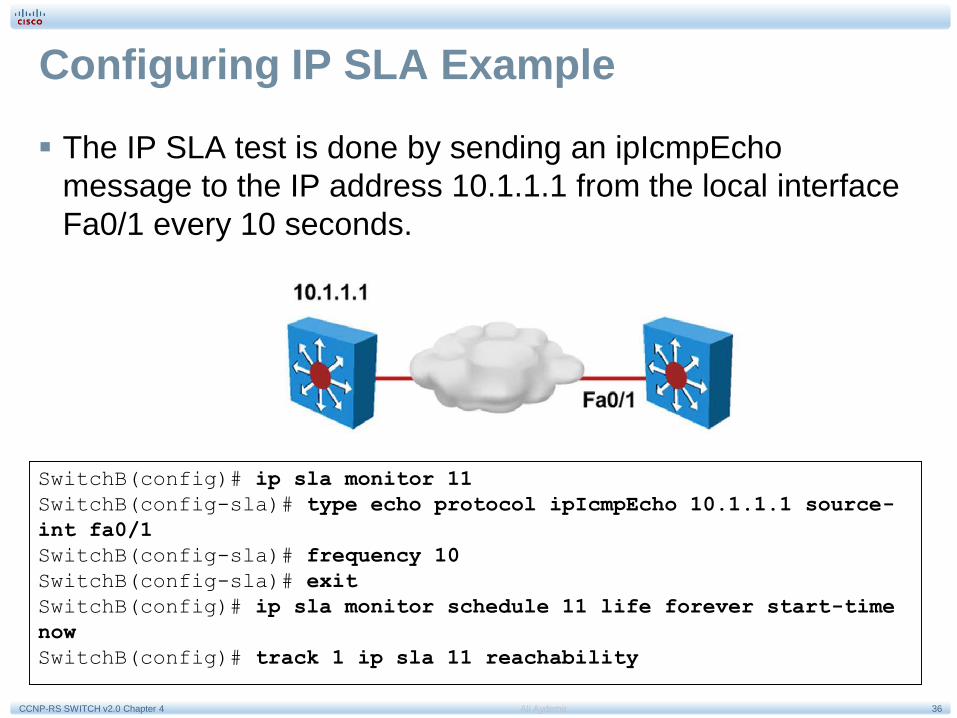
The IP SLA test is done by sending an ipIcmpEcho
message to the IP address 10.1.1.1 from the local interface
Fa0/1 every 10 seconds.
SwitchB(config)# ip sla monitor 11
SwitchB(config-sla)# type echo protocol ipIcmpEcho 10.1.1.1 source-
int fa0/1
SwitchB(config-sla)# frequency 10
SwitchB(config-sla)# exit
SwitchB(config)# ip sla monitor schedule 11 life forever start-time
now
SwitchB(config)# track 1 ip sla 11 reachability

37Ali AydemirCCNP-RS SWITCH v2.0 Chapter 4
Verifying IP SLA Configuration (1)
When IP SLA is configured, the test is conducted as per the
scheduled configuration. The test might succeed or fail. If
you do not monitor the test results, it might fail silently.
To display information about the test, use the show ip sla
statistics command.
Switch# show ip sla statistics
Round Trip Time (RTT) for Index 1
Latest RTT: NoConnection/Busy/Timeout
Latest operation start time: 11:11:22.533 eastern Thu Jul 9 2010
Latest operation return code: Timeout
Over thresholds occurred: FALSE
Number of successes: 177
Number of failures: 6
Operation time to live: Forever
Operational state of entry: Active
Last time this entry was reset: Never

38Ali AydemirCCNP-RS SWITCH v2.0 Chapter 4
Verifying IP SLA Configuration (2)
To get more information about a given IP SLA test configuration, use the show
ip sla configuration command. The example below shows a user
displaying IP SLA configuration.
Switch# show ip sla configuration
IP SLAs, Infrastructure Engine-II
Entry number: 1
Owner:
Tag:
Type of operation to perform: echo
Target address/Source address: 10.1.3.10/10.1.253.1
Type Of Service parameter: 0x0
Request size (ARR data portion): 28
Operation timeout (milliseconds): 5000
Verify data: No
Vrf Name:
Schedule:
Operation frequency (seconds): 5
Next Scheduled Start Time: Start Time already passed
Group Scheduled : FALSE
Randomly Scheduled : FALSE
Life (seconds): Forever
Entry Ageout (seconds): never
Recurring (Starting Everyday): FALSE
Status of entry (SNMP RowStatus): Active
Threshold (milliseconds): 5000
<output omitted>

39Ali AydemirCCNP-RS SWITCH v2.0 Chapter 4
Implementing Redundant Supervisor Engines in Catalyst Switches

40Ali AydemirCCNP-RS SWITCH v2.0 Chapter 4
Redundancy Features on Catalyst 4500/6500
RPR (Route Processor
Redundancy) and RPR+
(only on Catalyst 6500)
SSO (Stateful SwitchOver)
NSF (Non-Stop
Forwarding) with SSO
SE1
SE2

41Ali AydemirCCNP-RS SWITCH v2.0 Chapter 4
Route Processor Redundancy (RPR)
With RPR, any of the following events triggers a switchover from the
active to the standby Supervisor Engine:
• Route Processor (RP) or Switch Processor (SP) crash on the active
Supervisor Engine.
• A manual switchover from the CLI.
• Removal of the active Supervisor Engine.
• Clock synchronization failure between Supervisor Engines.
In a switchover, the redundant Supervisor Engine becomes fully
operational and the following events occur on the remaining modules
during an RPR failover:
• All switching modules are power-cycled.
• Remaining subsystems on the MSFC (including Layer 2 and Layer 3
protocols) are initialized on the prior standby, now active, Supervisor Engine.
• ACLs based on the new active Supervisor Engine are reprogrammed into the
Supervisor Engine hardware.

42Ali AydemirCCNP-RS SWITCH v2.0 Chapter 4
Route Processor Redundancy Plus (RPR+)
RPR+ enhances Supervisor redundancy compared to RPR by providing
the following additional benefits:
• Reduced switchover time: Depending on the configuration, the
switchover time is in the range of 30 seconds to 60 seconds.
• No reloading of installed modules: Because both the startup
configuration and the running configuration stay continually
synchronized from the active to the redundant Supervisor Engine
during a switchover, no reloading of line modules occurs.
• Synchronization of Online Insertion and Removal (OIR) events
between the active and standby: This occurs such that modules in
the online state remain online and modules in the down state remain
in the down state after a switchover.

43Ali AydemirCCNP-RS SWITCH v2.0 Chapter 4
RPR and RPR+ Failover Time Intervals
Redundancy Catalyst 6500 Failover Time Catalyst 4500 Failover Time
RPR 2-4 minutes Less than 60 seconds
RPR+ 30-60 seconds ---
44Ali AydemirCCNP-RS SWITCH v2.0 Chapter 4
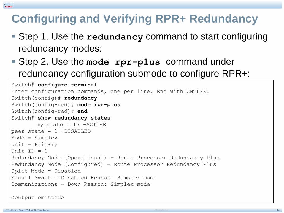
Configuring and Verifying RPR+ Redundancy
Step 1. Use the redundancy command to start configuring
redundancy modes:
Step 2. Use the mode rpr-plus command under
redundancy configuration submode to configure RPR+:Switch# configure terminal
Enter configuration commands, one per line. End with CNTL/Z.
Switch(config)# redundancy
Switch(config-red)# mode rpr-plus
Switch(config-red)# end
Switch# show redundancy states
my state = 13 –ACTIVE
peer state = 1 -DISABLED
Mode = Simplex
Unit = Primary
Unit ID = 1
Redundancy Mode (Operational) = Route Processor Redundancy Plus
Redundancy Mode (Configured) = Route Processor Redundancy Plus
Split Mode = Disabled
Manual Swact = Disabled Reason: Simplex mode
Communications = Down Reason: Simplex mode
<output omitted>

45Ali AydemirCCNP-RS SWITCH v2.0 Chapter 4
Stateful Switchover (SSO)
Provides minimal Layer 2 traffic disruption during
Supervisor switchover.
Redundant Supervisor starts up in fully initialized state and
synchronizes with startup configuration and running
configuration of active Supervisor.
Standby Supervisor in SSO mode keeps in sync with active
Supervisor for all changes in hardware and software states
for features supported via SSO.

46Ali AydemirCCNP-RS SWITCH v2.0 Chapter 4
Protocols and Features Supported by SSO
802.3x (Flow Control)
802.3ad (LACP) and PAgP
802.1X (Authentication) and Port security
802.3af (Inline power)
VTP
Dynamic ARP Inspection/DHCP snooping/IP source guard
IGMP snooping (versions 1 and 2)
DTP (802.1Q and ISL)
MST/PVST+/Rapid-PVST
PortFast/UplinkFast/BackboneFast /BPDU Guard and filtering
Voice VLAN
Unicast MAC filtering
ACL (VLAN ACLs, Port ACLs, Router ACLs)
QOS (DBL)
Multicast storm control/broadcast storm control

47Ali AydemirCCNP-RS SWITCH v2.0 Chapter 4
Configuring and Verifying SSO
Step 1. Enter the redundancy command to start configuring redundancy
modes.ancy
Step 2. Use the mode sso command under redundancy configuration
submode to configure RPR+:Switch# configure terminal
Enter configuration commands, one per line. End with CNTL/Z.
Switch(config)# redundancy
Switch(config-red)# mode sso
Changing to sso mode will reset the standby. Do you want to continue?
[confirm]
Switch(config-red)# end
Switch# show redundancy states
my state = 13 –ACTIVE
peer state = 8 -STANDBY HOT
Mode = Duplex
Unit = Primary
Unit ID = 2
Redundancy Mode (Operational) = Stateful Switchover
Redundancy Mode (Configured) = Stateful Switchover
Split Mode = Disabled
Manual Swact = Enabled
Communications = Up
<output omitted>

48Ali AydemirCCNP-RS SWITCH v2.0 Chapter 4
NSF with SSO
Catalyst 4500 and 6500.
Minimizes time that L3 network is unavailable following
Supervisor switchover by continuing to forward IP packets
using CEF entries built from the old active Supervisor.
Zero or near zero packet loss.
Supports BGP, EIGRP, OSPF, and IS-IS.
Routing protocol neighbor relationships are maintained
during Supervisor failover.
Prevents route flapping.

49Ali AydemirCCNP-RS SWITCH v2.0 Chapter 4
Configuring and Verifying NSF with SSO (1)
NSF is an additional configuration option for configuring SSO. To configure NSF for OSPF, EIGRP, and IS-IS, use the nsf router-level command. To
configure BGP for NSF support, use the bgp gracefulrestart router-
level command.
Switch# configure terminal
Enter configuration commands, one per line. End with CNTL/Z.
Switch(config)# router bgp 100
Switch(config-router)# bgp graceful-restart
Switch(config-router)# exit
Switch(config)#router ospf 200
Switch(config-router)# nsf
Switch(config-router)# end
Switch# show ip bgp neighbors 192.168.200.1
BGP neighbor is 192.168.200.1, remote AS 200, external link
BGP version 4, remote router ID 192.168.200.1
BGP state = Established, up for 00:01:23
Last read 00:00:17, hold time is 180, keepalive interval is 60 seconds
Neighbor capabilities:
Route refresh:advertised and received(new)
Address family IPv4 Unicast:advertised and received
Address family IPv4 Multicast:advertised and received
Graceful Restart Capability:advertised and received
Remote Restart timer is 120 seconds
Address families preserved by peer:
IPv4 Unicast, IPv4 Multicast
Received 1539 messages, 0 notifications, 0 in queue
Sent 100 messages, 0 notifications, 0 in queue
Default minimum time between advertisement runs is 30 seconds

50Ali AydemirCCNP-RS SWITCH v2.0 Chapter 4
Configuring and Verifying NSF with SSO (2)
Switch# show ip ospf
Routing Process “ospf 200” with ID 192.168.20.1 and Domain ID 0.0.0.1
Supports only single TOS(TOS0) routes
Supports opaque LSA
SPF schedule delay 5 secs, Hold time between two SPFs 10 secs
Minimum LSA interval 5 secs. Minimum LSA arrival 1 secs
Number of external LSA 0. Checksum Sum 0x0
Number of opaque AS LSA 0. Checksum Sum 0x0
Number of DCbitless external and opaque AS LSA 0
Number of DoNotAge external and opaque AS LSA 0
Number of areas in this router is 1. 1 normal 0 stub 0 nssa
External flood list length 0
Non-Stop Forwarding enabled, last NSF restart 00:02:36 ago (took 34 secs)
Area BACKBONE(0)
Number of interfaces in this area is 1 (0 loopback)
Area has no authentication
SPF algorithm executed 3 times

51Ali AydemirCCNP-RS SWITCH v2.0 Chapter 4
Understanding First Hop Redundancy Protocols
52Ali AydemirCCNP-RS SWITCH v2.0 Chapter 4
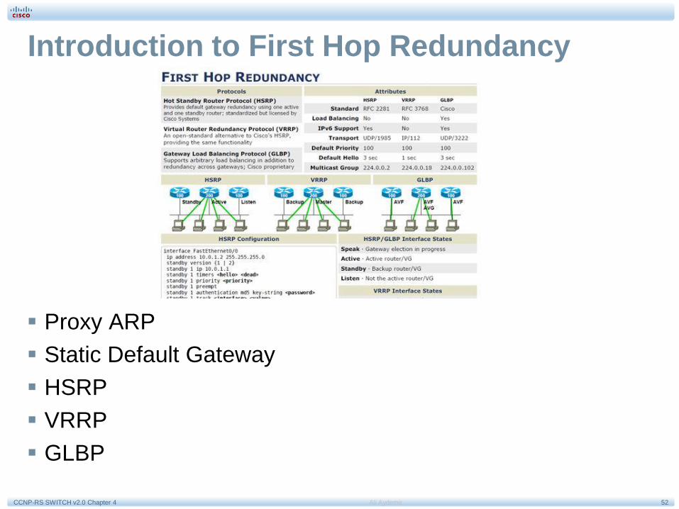
Introduction to First Hop Redundancy
Proxy ARP
Static Default Gateway
HSRP
VRRP
GLBP

53Ali AydemirCCNP-RS SWITCH v2.0 Chapter 4
Proxy ARP
Legacy solution.
Enabled by default.
Used before default
gateways were supported
on IP clients.
End station acts as if
destination were on same
network segment.
Relatively slow due to
reliance on aging out of
ARP cache.

54Ali AydemirCCNP-RS SWITCH v2.0 Chapter 4
Static Default Gateway
Not dynamic.
Does not provide
secondary path.

55Ali AydemirCCNP-RS SWITCH v2.0 Chapter 4
Hot Standby Router Protocol (HSRP)
Cisco-proprietary gateway
redundancy protocol.
Participating routers talk to
each other and agree on a
virtual router with a virtual
IP address which end
systems use as a default
gateway.

56Ali AydemirCCNP-RS SWITCH v2.0 Chapter 4
HSRP Failover
When active router or links
between routers fail, the
standby router stops
seeing hello messages
from active router. Standby
router then assumes role
of forwarding router.
Because new forwarding
router assumes both IP
and MAC address of
virtual router, end stations
see no disruption in
service.

57Ali AydemirCCNP-RS SWITCH v2.0 Chapter 4
HSRP Operation
HSRP active and standby routers send hello messages to
multicast address 224.0.0.2 UDP port 1985.
Hello messages used to communicated between routers
within HSRP group.
All routers in HSRP group need to be L2-adjacent.
All routers in an HSRP group have specific roles and
interact in specific ways:
• Virtual router
• Active router
• Standby router
• Other routers

58Ali AydemirCCNP-RS SWITCH v2.0 Chapter 4
HSRP MAC Address
Router A assumes the active role and forwards all frames
addressed to the assigned HSRP MAC address of
0000.0c07.acxx, where xx is the HSRP group identifier.

59Ali AydemirCCNP-RS SWITCH v2.0 Chapter 4
HSRP States
State Definition
Initial The beginning state. The initial state indicates that HSRP does not
run. This state is entered via a configuration change or when an
interface first comes up.
Listen The router knows the virtual IP address, but the router is neither the
active router nor the standby router. It listens for hello messages
from those routers.
Speak The router sends periodic hello messages and actively participates
in the election of the active or standby router. A router cannot enter
speak state unless the router has the virtual IP address.
Standby The router is a candidate to become the next active router and
sends periodic hello messages. With the exclusion of transient
conditions, there is, at most, one router in the group in standby
state.
Active The router currently forwards packets that are sent to the group
virtual MAC address. The router sends periodic hello messages.
With the exclusion of transient conditions, there must be, at the
most, one router in the active state in the group.

60Ali AydemirCCNP-RS SWITCH v2.0 Chapter 4
HSRP State Transition
Router A starts. As it is the first router for standby Group 1 in the subnet,
it transits through the listen and speak states and then becomes the
active router.
Router B starts after Router A. While Router B is in listen state, Router
A is already assuming the standby and then the active role. As there is
already an existing active router, Router B assumes the standby role.

61Ali AydemirCCNP-RS SWITCH v2.0 Chapter 4
HSRP Active Router and Spanning Tree Topology
In a redundant spanning-tree topology, some links are blocked. The spanning-
tree topology has no awareness about the HSRP configuration. There is no
automatic relationship between the HSRP active router election process and the
Spanning Tree Root Bridge election.
When configuring both spanning tree and HSRP (or any other first hop
redundancy protocol), you must make sure that the active router is the same as
the root bridge for the corresponding VLAN. When the root bridge is different
from the HSRP active router, a suboptimal path can result, as illustrated.
62Ali AydemirCCNP-RS SWITCH v2.0 Chapter 4
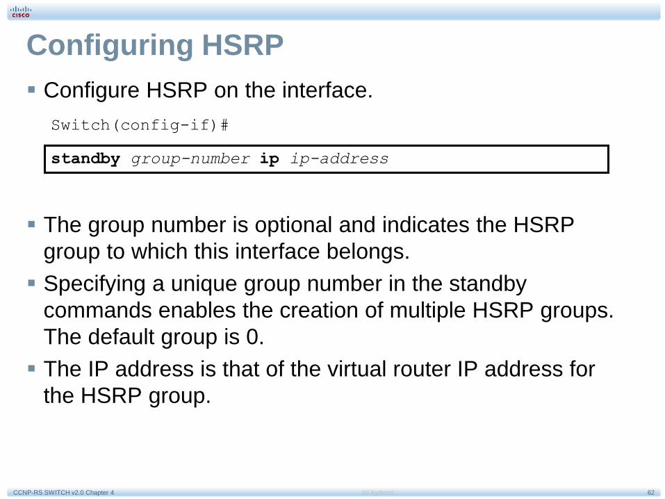
Configuring HSRP
Configure HSRP on the interface.
Switch(config-if)#
standby group-number ip ip-address
The group number is optional and indicates the HSRP
group to which this interface belongs.
Specifying a unique group number in the standby
commands enables the creation of multiple HSRP groups.
The default group is 0.
The IP address is that of the virtual router IP address for
the HSRP group.

63Ali AydemirCCNP-RS SWITCH v2.0 Chapter 4
Configuring HSRP Priority and Preempt
To set the HSRP priority value of a router, enter this command in
interface configuration mode:
standby group-number priority priority-value
The priority value can be from 0 to 255. The default value is 100.
During the election process, the router with the highest priority in an
HSRP group becomes the active router. If a tie occurs, the router with
the highest configured IP address becomes active.
If the routers do not have preempt configured, a router that boots up
significantly faster than the others in the standby group becomes the
active router, regardless of the configured priority. The former active
router can be configured to resume the forwarding router role by
preempting a router with a lower priority.
To enable a router to resume the forwarding router role, enter this
command in interface configuration mode:
standby [group-number] preempt [delay {minimum seconds reload
seconds sync seconds}]

64Ali AydemirCCNP-RS SWITCH v2.0 Chapter 4
HSRP Configuration Example
Routers A and B are configured with priorities of 110 and
90, respectively. The configuration of Router A is displayed.
The preempt keyword ensures that Router A will be the
HSRP active router as long its interface is active.
RouterA(config)# interface vlan 10
RouterA(config-if)# ip address 10.1.1.2 255.255.255.0
RouterA(config-if)# standby 10 ip 10.1.1.1
RouterA(config-if)# standby 10 priority 110
RouterA(config-if)# standby 10 preempt

65Ali AydemirCCNP-RS SWITCH v2.0 Chapter 4
HSRP Authentication Example
HSRP authentication prevents rogue routers on the network from joining
the HSRP group. HSRP authentication is enabled by configuration of an
authentication string on all member devices of the HSRP group.
The authentication string is a maximum of 8 characters and the default keyword is cisco.
RouterA(config)# interface vlan 10
RouterA(config-if)# ip address 10.1.1.2 255.255.255.0
RouterA(config-if)# standby 10 ip 10.1.1.1
RouterA(config-if)# standby 10 priority 110
RouterA(config-if)# standby 10 preempt
RouterA(config-if)# standby 10 authentication xyz123

66Ali AydemirCCNP-RS SWITCH v2.0 Chapter 4
HSRP Timer Considerations and Configuration
Variable Description
group-number (Optional) Group number
on the interface to which
the timers apply.
The default is 0.
msec (Optional) Interval in
milliseconds. Millisecond
timers allow for faster
failover.
hellotime Hello interval in seconds.
This is an integer from 1
through 255. The
default is 3 seconds.
holdtime Time, in seconds, before
the active or standby
router is declared to be
down. This is an integer
from 1 through 255. The
default is 10 seconds.

67Ali AydemirCCNP-RS SWITCH v2.0 Chapter 4
HSRP Timers Configuration Example
RouterA(config)# interface vlan 10
RouterA(config-if)# ip address 10.1.1.2 255.255.255.0
RouterA(config-if)# standby 10 ip 10.1.1.1
RouterA(config-if)# standby 10 priority 110
RouterA(config-if)# standby 10 preempt
RouterA(config-if)# standby 10 authentication xyz123
RouterA(config-if)# standby 10 timers msec 200 msec 750
RouterA(config-if)# standby 10 preempt delay minimum 225

68Ali AydemirCCNP-RS SWITCH v2.0 Chapter 4
HSRP Versions
HSRP version 1 is the default in IOS and it enables group numbers up to 255.
Because one can have up to 4095 VLANs, one has to reuse the same HSRP group
number on multiple interfaces if needed. This is allowed even though it might cause
some confusion.
HSRPv1 uses the Virtual MAC address of the form 0000.0C07.ACXX (XX = HSRP
group), and the HSRPv1 hello packets are sent to multicast address 224.0.0.2.
HSRP version 2 has been added to IOS since 12.2 46SE or later and it enables
group numbers up to 4095. This enables you to use the VLAN number as the group
number.
With HSRPv2, the MAC address of the virtual router and the multicast address for
the hello messages has been changed. The virtual MAC address is
0000.0C9F.FXXX (XXX=HSRP group), and hello packets are sent to multicast
address 224.0.0.102.
Also, HSRPv2 has a different packet format from HSRPv1. Ensure that the same
version is configured on all routers in a HSRP group. Otherwise hello messages are
not understood. Version 1 is the default.
Use the following command to change the version:
Switch(config-if)# standby <hsrp group number> version 2
69Ali AydemirCCNP-RS SWITCH v2.0 Chapter 4
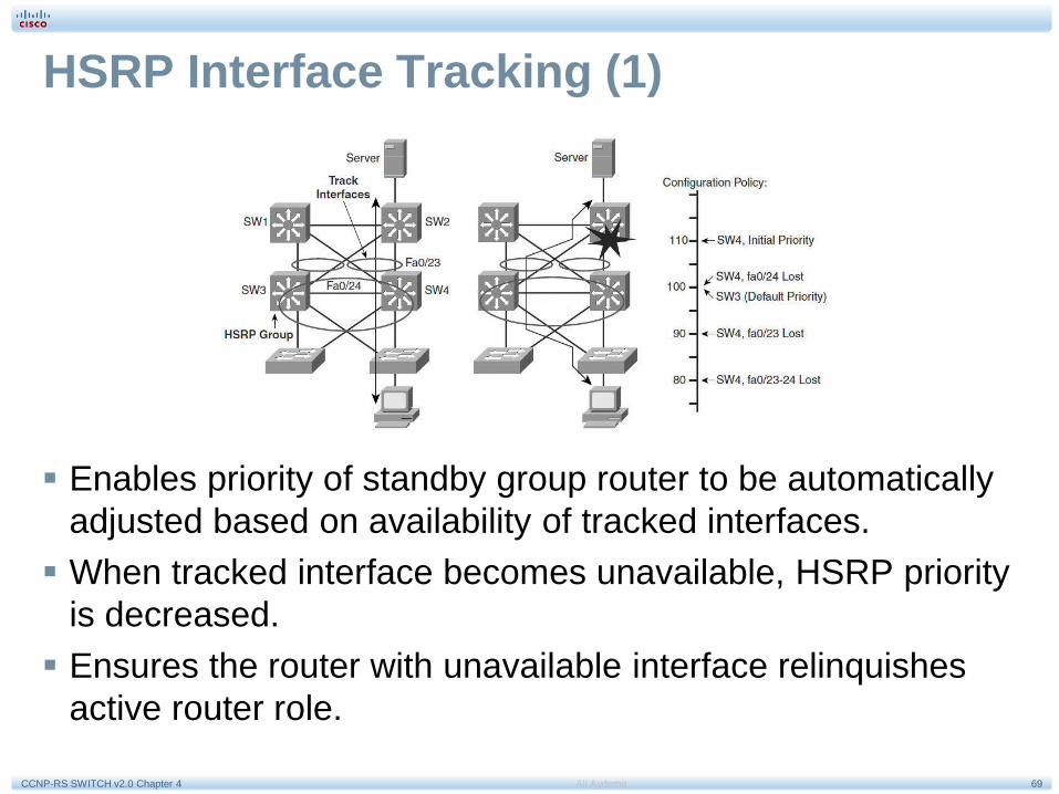
HSRP Interface Tracking (1)
Enables priority of standby group router to be automatically
adjusted based on availability of tracked interfaces.
When tracked interface becomes unavailable, HSRP priority
is decreased.
Ensures the router with unavailable interface relinquishes
active router role.

70Ali AydemirCCNP-RS SWITCH v2.0 Chapter 4
HSRP Interface Tracking (2)
Configure interface tracking.Switch(config-if)
standby [group-number] track interface-type interface-
number [interface-priority]
Variable Description
group-number (Optional) Indicates the group number on the interface to
which the tracking applies. The default number is 0.
interface-type Indicates the interface type (combined with the interface
number) that will be tracked.
interface-
number
Indicates the interface number (combined with the interface
type) that will be tracked.
interface-
priority
(Optional) Indicates the amount by which the hot standby
priority for the router is decremented when the interface
becomes disabled. The priority of the router is incremented
by this amount when the interface becomes available. The
default value is 10.

71Ali AydemirCCNP-RS SWITCH v2.0 Chapter 4
HSRP Interface Tracking (3)
To configure HSRP with interface tracking, follow these steps:
Step 1. Configure the standby group.
Step 2. Configure priority (default 100).
Step 3. Configure preempt on all devices within the HSRP group.
Step 4. Configure the tracked interfaces and decrement (default
decrement 10).

72Ali AydemirCCNP-RS SWITCH v2.0 Chapter 4
HSRP Interface Tracking (4)
SW4(config)# interface vlan 10
SW4(config-if)# ip address 10.1.1.2 255.255.255.0
SW4(config-if)# standby 10 ip 10.1.1.1
SW4(config-if)# standby 10 priority 110
SW4(config-if)# standby 10 preempt
SW4(config-if)# standby 10 track fastethernet0/23 20
SW4(config-if)# standby 10 track fastethernet0/24

73Ali AydemirCCNP-RS SWITCH v2.0 Chapter 4
HSRP Object Tracking
The HSRP tracking feature can be used to track an object.
When the conditions defined by this object are fulfilled, the
router priority remains the same. As soon as the verification
defined by the object fails, the router priority is
decremented.
Tracked objects are defined in global configuration with the track keyword, followed by an object number.
You can track up to 500 objects.
Switch(config)# track 1 ?
interface Select an interface to track
ip IP protocol
list Group objects in a list
rtr Response Time Reporter (RTR) entry

74Ali AydemirCCNP-RS SWITCH v2.0 Chapter 4
HSRP and IP SLA Tracking

75Ali AydemirCCNP-RS SWITCH v2.0 Chapter 4
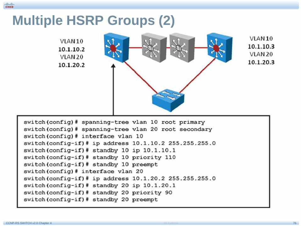
Multiple HSRP Groups (1)
HSRP allows for only one active router in the same subnet. In a typical network,
engineers would want to use all available routers to load share the traffic going
across the network. Multigroup HSRP enables routers to simultaneously provide
redundant backup and perform load sharing across different IP subnets.
In the figure, two HSRP-enabled routers participate in two separate VLANs,
using 802.1Q. Running HSRP over trunks enables users to configure
redundancy among multiple routers that are configured as front ends for VLAN
IP subnets.
76Ali AydemirCCNP-RS SWITCH v2.0 Chapter 4
Multiple HSRP Groups (2)

77Ali AydemirCCNP-RS SWITCH v2.0 Chapter 4
HSRP Monitoring (1)
Use the show standby family of commands to verify HSRP state.
Several arguments can be used.
The show standby brief command displays a summary of the
HSRP configurations.
For each standby group, you can verify the local router neighbors.
Switch# show standby brief
P indicates configured to preempt.
|
Interface Grp Pri P State Active Standby Virtual IP
Vl10 10 120 P Active local 10.1.10.3 10.1.10.1
Vl20 20 90 P Standby 10.1.20.3 local 10.1.20.1
Switch#show standby neighbor vlan10
HSRP neighbors on Vlan10
10.1.10.3
Active groups: 10
No standby groups

78Ali AydemirCCNP-RS SWITCH v2.0 Chapter 4
HSRP Monitoring (2)
Switch# show standby
Vlan10 - Group 10
State is Active
Virtual IP address is 10.1.10.1
Active virtual MAC address is 0000.0c07.ac0a
Local virtual MAC address is 0000.0c07.ac0a (v1 default)
Hello time 3 sec, hold time 10 sec
Next hello sent in 1.248 secs
Preemption enabled
Active router is local
Standby router is 10.1.10.3, priority 90 (expires in 10.096 sec)
Priority 120 (configured 120)
Track interface Port-channel31 state Up decrement 30
Track interface Port-channel32 state Up decrement 30
Group name is “hsrp-Vl10-10” (default)
Vlan20 - Group 20
State is Standby
Virtual IP address is 10.1.20.1 Active virtual MAC address is 0000.0c07.ac14
Local virtual MAC address is 0000.0c07.ac14 (v1 default)
Hello time 3 sec, hold time 10 sec
Next hello sent in 2.064 secs
Preemption enabled
Active router is 10.1.10.3, priority 120 (expires in 10.032 sec)
Standby router is local
Priority 90 (configured 90)
Group name is “hsrp-Vl20-20” (default)
When simply typing show standby, a complete display is provided.

79Ali AydemirCCNP-RS SWITCH v2.0 Chapter 4
HSRP Monitoring (3)
The IP address and corresponding MAC address of the virtual router
are maintained in the ARP table of each router in an HSRP group.
The command show ip arp displays the ARP cache on a multilayer
switch.

80Ali AydemirCCNP-RS SWITCH v2.0 Chapter 4
HSRP Debug Commands
Command Description
Switch# debug standby
[errors] [events] [packets]
Displays all state changes to HSRP,
including all hello packets. Arguments
minimize output.
Switch# debug standby terse Displays all HSRP errors, events, and
packets,
except hello and advertisement
packets.

81Ali AydemirCCNP-RS SWITCH v2.0 Chapter 4
Virtual Router Redundancy Protocol (VRRP)
HSRP VRRP
HSRP is a Cisco proprietary protocol,
created in 1994, and formalized with the RFC 2281 in March 1998.
VRRP is an IEEE standard (RFC 2338 in 1998; then RFC
3768 in 2005) for router redundancy.
16 groups max. 255 groups max.
1 active, 1 standby, several candidates. 1 active, several backups.
Virtual IP is different from Active andStandby real IP addresses.
Virtual IP can be the same as one of the
group members real IP address.
Uses 224.0.0.2 for hello packets. Uses 224.0.0.18 for hello packets.
Default timers: hello 3 s, holdtime 10 s. The default timers are shorter in VRRP than HSRP. This
often gave VRRP the reputation of being faster than HSRP.
Can track interfaces or objects. Can track only objects.
Uses authentication within each group by
default. When authentication is not
configured, a default authentication, using “cisco” as the password.
Supports plaintext and HMAC/MD5 authentication methods
(RFC 2338). The new VRRP RFC (RFC 3768) removes
support for these methods. The consequence is that VRRP
does not support authentication anymore. Nevertheless,
current Cisco IOS still supports the RFC 2338
authentications mechanisms.

82Ali AydemirCCNP-RS SWITCH v2.0 Chapter 4
VRRP Scenario
Routers A, B, and C are members of a VRRP group. The IP address of the
virtual router is the same as that of the LAN interface of Router A (10.0.0.1).
Router A is responsible for forwarding packets sent to this IP address.
The clients have a gateway address of 10.0.0.1. Routers B and C are backup
routers. If the master router fails, the backup router with the highest priority
becomes the master router. When Router A recovers, it resumes the role of
master router.

83Ali AydemirCCNP-RS SWITCH v2.0 Chapter 4
VRRP Scenario (1)
Here is a LAN topology in which VRRP is configured so that Routers A and B share the
load of being the default gateway for Clients 1 through 4. Routers A and B act as backup
virtual routers to one another should either one fail.
Two virtual router groups are configured. For virtual Router 1, Router A is the owner of IP
address 10.0.0.1 and is therefore the master virtual router for clients configured with that
default gateway address. Router B is the backup virtual router to Router A.
For virtual Router 2, Router B is the owner of IP address 10.0.0.2 and is the master virtual
router for clients configured with the default gateway IP address 10.0.0.2. Router A is the
backup virtual router to Router B.
84Ali AydemirCCNP-RS SWITCH v2.0 Chapter 4
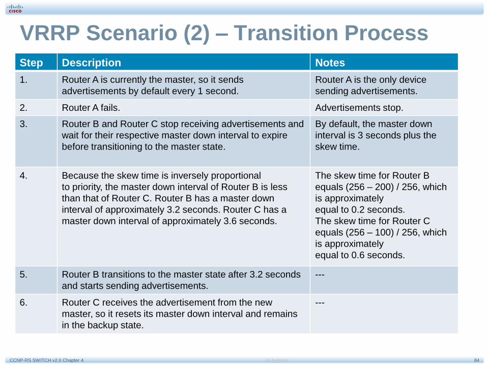
VRRP Scenario (2) – Transition Process
Step Description Notes
1. Router A is currently the master, so it sends
advertisements by default every 1 second.
Router A is the only device
sending advertisements.
2. Router A fails. Advertisements stop.
3. Router B and Router C stop receiving advertisements and
wait for their respective master down interval to expire
before transitioning to the master state.
By default, the master down
interval is 3 seconds plus the
skew time.
4. Because the skew time is inversely proportional
to priority, the master down interval of Router B is less
than that of Router C. Router B has a master down
interval of approximately 3.2 seconds. Router C has a
master down interval of approximately 3.6 seconds.
The skew time for Router B
equals (256 – 200) / 256, which
is approximately
equal to 0.2 seconds.
The skew time for Router C
equals (256 – 100) / 256, which
is approximately
equal to 0.6 seconds.
5. Router B transitions to the master state after 3.2 seconds
and starts sending advertisements.
---
6. Router C receives the advertisement from the new
master, so it resets its master down interval and remains
in the backup state.
---

85Ali AydemirCCNP-RS SWITCH v2.0 Chapter 4
Configuring VRRP
Step Description
1. To enable VRRP on an interface. This makes the interface a member
of the virtual group identified with the IP virtual address:
Switch(config-if)# vrrp group-number ip virtual-
gateway-address
2. To set a VRRP priority for this router for this VRRP group: Highest
value wins election as active router. Default is 100. If routers have the
same VRRP priority, the gateway with the highest real IP address is
elected to become the master virtual router:
Switch(config-if)# vrrp group-number priority
priority-value
3. To change timer and indicate if it should advertise for master or just
learn for backup routers:
Switch(config-if)# vrrp group-number timers
advertise timer-value
Switch(config-if)# vrrp group-number timers learn

86Ali AydemirCCNP-RS SWITCH v2.0 Chapter 4
VRRP Configuration Example (1)
RouterA# configure terminal
Enter configuration commands, one per line. End with CNTL/Z.
RouterA(config)# interface vlan 1
RouterA(config-if)# ip address 10.0.2.1 255.255.255.0
RouterA(config-if)# vrrp 1 ip 10.0.2.254
RouterA(config-if)# vrrp 1 timers advertise msec 500
RouterA(config-if)# end
RouterB# configure terminal
Enter configuration commands, one per line. End with CNTL/Z.
RouterB(config)# interface vlan 1
RouterB(config-if)# ip address 10.0.2.2 255.255.255.0
RouterB(config-if)# vrrp 1 ip 10.0.2.254
RouterB(config-if)# vrrp 1 priority 90
RouterB(config-if)# vrrp 1 timers learn
RouterB(config-if)# end
87Ali AydemirCCNP-RS SWITCH v2.0 Chapter 4
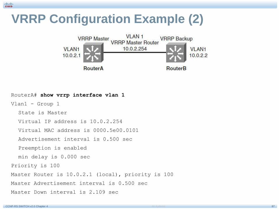
VRRP Configuration Example (2)
RouterA# show vrrp interface vlan 1
Vlan1 - Group 1
State is Master
Virtual IP address is 10.0.2.254
Virtual MAC address is 0000.5e00.0101
Advertisement interval is 0.500 sec
Preemption is enabled
min delay is 0.000 sec
Priority is 100
Master Router is 10.0.2.1 (local), priority is 100
Master Advertisement interval is 0.500 sec
Master Down interval is 2.109 sec

88Ali AydemirCCNP-RS SWITCH v2.0 Chapter 4
VRRP Configuration Example (3)
RouterB# show vrrp interface vlan 1
Vlan1 - Group 1
State is Backup
Virtual IP address is 10.0.2.254
Virtual MAC address is 0000.5e00.0101
Advertisement interval is 0.500 sec
Preemption is enabled
min delay is 0.000 sec
Priority is 90
Master Router is 10.0.2.1, priority is 100
Master Advertisement interval is 0.500 sec
Master Down interval is 2.109 sec (expires in 1.745 sec)

89Ali AydemirCCNP-RS SWITCH v2.0 Chapter 4
Gateway Load Balancing Protocol (GLBP)
HSRP GLBP
Cisco Proprietary, 1994 Cisco Proprietary, 2005
16 groups max. 1024 groups max.
1 active, 1 standby, several candidates. 1 AVG, several AVF, AVG load balances
traffic
among AVF and AVGs
Virtual IP is different from Active andStandby real IP addresses.
Virtual IP is different from AVG and AVF real
IP addresses
1 Virtual MAC address for each group 1 Virtual MAC address per AVF/AVG in
each group
Uses 224.0.0.2 for hello packets. Uses 224.0.0.102 for hello packets.
Default timers: hello 3 s, holdtime 10 s. The default timers are shorter in VRRP than
HSRP. This often gave VRRP the reputation
of being faster than HSRP.
Can track interfaces or objects. Can track only objects.
Default timers: hello 3 s, holdtime 10 s Default timers: hello 3 s, holdtime 10 s
Authentication supported Authentication supported

90Ali AydemirCCNP-RS SWITCH v2.0 Chapter 4
GLBP Functions (1)
GLBP active virtual gateway (AVG):Members of a GLBP group elect one gateway to be
the AVG for that group. Other group members provide backup for the AVG if the AVG
becomes unavailable. The AVG assigns a virtual MAC address to each member of the
GLBP group.
GLBP active virtual forwarder (AVF): Each gateway assumes responsibility for
forwarding packets that are sent to the virtual MAC address assigned to that gateway by
the AVG. These gateways are known as AVFs for their virtual MAC address.
GLBP communication: GLBP members communicate between each other through hello
messages sent every 3 seconds to the multicast address 224.0.0.102, User Datagram
Protocol (UDP) port 3222.
91Ali AydemirCCNP-RS SWITCH v2.0 Chapter 4
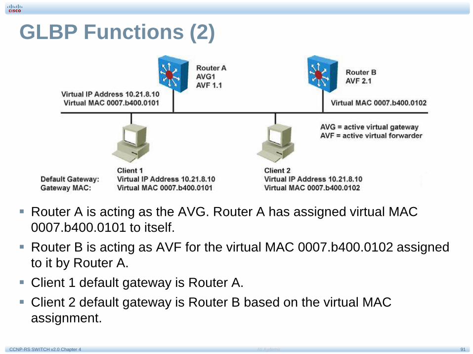
GLBP Functions (2)
Router A is acting as the AVG. Router A has assigned virtual MAC
0007.b400.0101 to itself.
Router B is acting as AVF for the virtual MAC 0007.b400.0102 assigned
to it by Router A.
Client 1 default gateway is Router A.
Client 2 default gateway is Router B based on the virtual MAC
assignment.

92Ali AydemirCCNP-RS SWITCH v2.0 Chapter 4
GLBP Features
Load sharing: You can configure GLBP in such a way that multiple
routers can share traffic from LAN clients, thereby sharing the traffic
load more equitably among available routers.
Multiple virtual routers: GLBP supports up to 1024 virtual routers
(GLBP groups) on each physical interface of a router and up to four
virtual forwarders per group.
Preemption: The redundancy scheme of GLBP enables you to preempt
an AVG with a higher priority backup virtual gateway that has become
available. Forwarder preemption works in a similar way, except that
forwarder preemption uses weighting instead of priority and is enabled
by default.
Efficient resource utilization: GLBP makes it possible for any router in
a group to serve as a backup, which eliminates the need for a dedicated
backup router because all available routers can support network traffic.

93Ali AydemirCCNP-RS SWITCH v2.0 Chapter 4
GLBP Operations (1)
Operational modes for load balancing:
Weighted load-balancing algorithm: The amount of load
directed to a router is dependent upon the weighting value
advertised by that router.
Host-dependent load-balancing algorithm: A host is
guaranteed use of the same virtual MAC address as long as
that virtual MAC address is participating in the GLBP group.
Round-robin load-balancing algorithm: As clients send
ARP requests to resolve the MAC address of the default
gateway, the reply to each client contains the MAC address
of the next possible router in round-robin fashion. All
routers’ MAC addresses take turns being included in
address resolution replies for the default gateway IP
address.
94Ali AydemirCCNP-RS SWITCH v2.0 Chapter 4
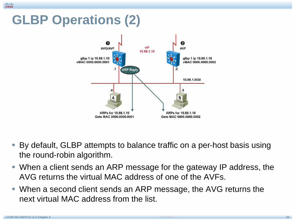
GLBP Operations (2)
By default, GLBP attempts to balance traffic on a per-host basis using
the round-robin algorithm.
When a client sends an ARP message for the gateway IP address, the
AVG returns the virtual MAC address of one of the AVFs.
When a second client sends an ARP message, the AVG returns the
next virtual MAC address from the list.
95Ali AydemirCCNP-RS SWITCH v2.0 Chapter 4
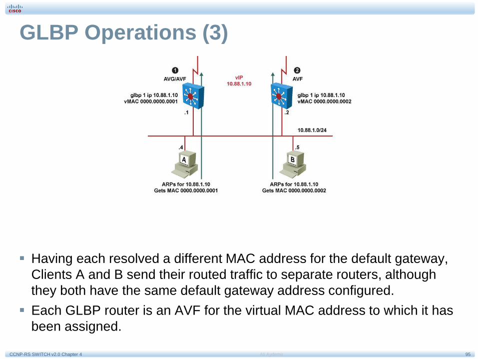
GLBP Operations (3)
Having each resolved a different MAC address for the default gateway,
Clients A and B send their routed traffic to separate routers, although
they both have the same default gateway address configured.
Each GLBP router is an AVF for the virtual MAC address to which it has
been assigned.

96Ali AydemirCCNP-RS SWITCH v2.0 Chapter 4
GLBP Interface Tracking (1)
Like HSRP, GLBP can be configured to track interfaces.
The WAN link from Router R1 is lost. GLBP detects the failure. Just like
HSRP, GLBP decrements the gateway priority when a tracked interface
fails. The second gateway then becomes primary. This transition is
transparent for the LAN client.

97Ali AydemirCCNP-RS SWITCH v2.0 Chapter 4
GLBP Interface Tracking (2)
Because interface tracking was configured on R1, the job of forwarding
packets for virtual MAC address 0000.0000.0001 will be taken over by
the secondary virtual forwarder for the MAC, Router R2. Therefore, the
client sees no disruption of service nor does the client need to resolve a
new MAC address for the default gateway.

98Ali AydemirCCNP-RS SWITCH v2.0 Chapter 4
GLBP Interface Tracking (3)
SW4 is forwarding. Its initial weight (or priority) is 110.
SW4 tracks both Fa0/23 and Fa0/24 interfaces. Fa0/23 is the active interface.
Losing fa0/23 decrements SW4 by 20 points, thus bringing SW4’s weight down
(from 110) to 90. Fa0/24 is a backup interface.
Losing Fa0/24 decrements SW4 by 10 points, thus bringing SW4’s weight down
(from 110) to 100, which is the default weight of the other routers.
Losing both Fa0/23 and Fa0/24 brings SW4’s weight down (from 110) to 80.

99Ali AydemirCCNP-RS SWITCH v2.0 Chapter 4
GLBP Interface Tracking (4)

100Ali AydemirCCNP-RS SWITCH v2.0 Chapter 4
Configuring GLBP
Step Description
1. Enable GLBP on an interface. This command makes the interface a
member of the virtual group identified with the IP virtual address:
Switch(config-if)#glbp group-number ip virtual-
gateway-address
2. Set a GLBP priority for this router for this GLBP group. The highest
value wins election as active router. The default is 100. If routers have
the same GLBP priority, the gateway with the highest real IP address
becomes the AVG:
Switch(config-if)#glbp group-number priority
priority-value
3. Change timer values for hello interval and holdtime. Place the argument
msec before the values to enter subsecond values:
Switch(config-if)#glbp group-number timers hello
holdtime

101Ali AydemirCCNP-RS SWITCH v2.0 Chapter 4
GLBP with VLAN Spanning Access Switches
Although invisible and transparent to VLAN 2 clients, the STP blocking state on
the access uplink results in the frames coming from VLAN 2 transiting through
Distribution A and then through Distribution B before being sent to the core.
In environments in which VLANs span across access switches, HSRP is the
recommended first hop redundancy protocol implementation. In all cases, the
active gateway should be configured to also be the root bridge for the VLAN in
which first hop redundancy is configured.

102Ali AydemirCCNP-RS SWITCH v2.0 Chapter 4
Cisco IOS Server Load Balancing

103Ali AydemirCCNP-RS SWITCH v2.0 Chapter 4
Cisco IOS SLB Benefits
High performance is achieved through the distribution of client requests across a cluster
of servers.
Administration of server applications is easier. Clients know only about virtual servers; no
administration is required for real server changes, making Cisco IOS SLB highly scalable.
Security of the real server is provided because its address is never announced to the
external network. Users are familiar only with the virtual IP address. Additionally, filtering
of unwanted traffic can be based on both IP address and IP port numbers.
Ease of maintenance with no downtime is achieved by allowing physical (real) servers to
be transparently placed in or out of service while other servers handle client requests.
Switches detect servers that are not responding and do not forward further requests to
those servers until they begin to respond to polls from the switch.

104Ali AydemirCCNP-RS SWITCH v2.0 Chapter 4
SLB Virtual Server and Server Farm
Cisco IOS SLB enables users to represent a group of network servers (a server
farm in a data center) as a single server instance, balance the traffic to the
servers, and limit traffic to individual servers. The single server instance that
represents a server farm is referred to as a virtual server.
The graphic above shows Cisco IOS SLB applied to a server farm in a data
center. The virtual web server IP address is 192.168.1.200 on port 80, and the
real web servers are 192.168.1.1 and 192.168.1.2.
Any request to the virtual web server address is served by the two real servers.

105Ali AydemirCCNP-RS SWITCH v2.0 Chapter 4
Cisco IOS SLB Modes of Operation
Cisco IOS SLB supports the following redirection modes:
Dispatched mode: Each of the real servers is configured with the
virtual server address as a loopback address or secondary IP address.
Cisco IOS SLB redirects packets to the real servers at the MAC layer.
Because the virtual server IP address is not modified in dispatched
mode, the real servers must be Layer 2–adjacent to Cisco IOS SLB or
intervening routers might not route to the chosen real server.
Directed mode: The virtual server can be assigned an IP address that
is not known to any of the real servers in a data center. Cisco IOS SLB
translates packets exchanged between a client and a real server,
translating the virtual server IP address to a real server address via
Network Address Translation (NAT). For more information about Cisco
IOS SLB support of different NAT types, refer to the Cisco IOS SLB
configuration section of the Cisco product documentation for the
Catalyst 6500 switches.
106Ali AydemirCCNP-RS SWITCH v2.0 Chapter 4
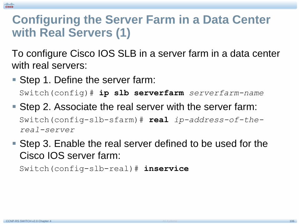
Configuring the Server Farm in a Data Center with Real Servers (1)
To configure Cisco IOS SLB in a server farm in a data center
with real servers:
Step 1. Define the server farm:
Switch(config)# ip slb serverfarm serverfarm-name
Step 2. Associate the real server with the server farm:
Switch(config-slb-sfarm)# real ip-address-of-the-
real-server
Step 3. Enable the real server defined to be used for the
Cisco IOS server farm:
Switch(config-slb-real)# inservice

107Ali AydemirCCNP-RS SWITCH v2.0 Chapter 4
Configuring the Server Farm in a Data Center with Real Servers (2)
Two server farms in a data center,
PUBLIC and RESTRICTED, are
configured.
The PUBLIC server farm has
associated with it three real servers:
10.1.1.1, 10.1.1.2, and 10.1.1.3.
The RESTRICTED server farm has
two real servers associated with it:
10.1.1.20 and 10.1.1.21.
Switch# configure terminal
Enter configuration commands, one per line. End with CNTL/Z.
Switch(config)# ip slb serverfarm PUBLIC
Switch(config-slb-sfarm)# real 10.1.1.1
Switch(config-slb-real)# inservice
Switch(config-slb-real)# exit
Switch(config-slb-sfarm)# real 10.1.1.2
Switch(config-slb-real)# inservice
Switch(config-slb-real)# exit
Switch(config-slb-sfarm)# real 10.1.1.3
Switch(config-slb-real)# inservice
Switch(config-slb-real)# exit
Switch(config-slb-sfarm)# exit

108Ali AydemirCCNP-RS SWITCH v2.0 Chapter 4
Configuring the Server Farm in a Data Center with Real Servers (3)
Two server farms in a data
center, PUBLIC and
RESTRICTED, are configured.
The PUBLIC server farm has
associated with it three real
servers: 10.1.1.1, 10.1.1.2, and
10.1.1.3.
The RESTRICTED server farm
has two real servers associated
with it: 10.1.1.20 and 10.1.1.21.
Switch(config)# ip slb serverfarm RESTRICTED
Switch(config-slb-sfarm)# real 10.1.1.20
Switch(config-slb-real)# inservice
Switch(config-slb-real)# exit
Switch(config-slb-sfarm)# real 10.1.1.21
Switch(config-slb-real)# inservice
Switch(config-slb-real)# end

109Ali AydemirCCNP-RS SWITCH v2.0 Chapter 4
Configuring the Server Farm in a Data Center with Real Servers (4) Displaying the status and
configuration of the server farms
PUBLIC and RESTRICTED, the
associated real servers, and their
status.
Switch# show ip slb real
real farm name weight state cons
– – – – – – – – – – – – – – – – – – – – – – – – – – – – – – – – –
10.1.1.1 PUBLIC 8 OPERATIONAL 0
10.1.1.2 PUBLIC 8 OPERATIONAL 0
10.1.1.3 PUBLIC 8 OPERATIONAL 0
10.1.1.20 RESTRICTED 8 OPERATIONAL 0
10.1.1.21 RESTRICTED 8 OPERATIONAL 0
Switch# show ip slb serverfarm
server farm predictor nat reals bind id
– – – – – – – – – – – – – – – – – – – – – – – – – - - - - -
PUBLIC ROUNDROBIN none 3 0
RESTRICTED ROUNDROBIN none 2 0

110Ali AydemirCCNP-RS SWITCH v2.0 Chapter 4
Configuring the Server Farm in a Data Center with Virtual Servers (1)
To configure Cisco IOS SLB in a server farm in a data center with virtual servers:
Step 1. Define the virtual server:
Switch(config)# ip slb vserver vserver-name
Step 2. Configure the IP address of the virtual server:
Switch(config-slb-vserver)# virtual ip-address [network-mask] {tcp
| udp} [port-number | wsp | wsp-wtp | wsp-wtls | wsp-wtp-wtls]
[service service-name]
Step 3. Associate the primary and secondary server farm to the virtual server:
Switch(config-slb-vserver)# serverfarm primary-serverfarm-name
[backup backup-serverfarm-name [sticky]]
Step 4. Enable the virtual server:
Switch(config-slb-vserver)# inservice
Step 5. Specify the clients allowed to access the virtual server:
Switch(config-slb-vserver)# client ip-address network-mask

111Ali AydemirCCNP-RS SWITCH v2.0 Chapter 4
Configuring the Server Farm in a Data Center with Virtual Servers (2)
Switch(config)# ip slb vserver PUBLIC_HTTP
Switch(config-slb-vserver)# virtual 10.1.1.100 tcp www
Switch(config-slb-vserver)# serverfarm PUBLIC
Switch(config-slb-vserver)# inservice
Switch(config-slb-vserver)# exit
Switch(config)# ip slb vserver RESTRICTED_HTTP
Switch(config-slb-vserver)# virtual 10.1.1.200 tcp www
Switch(config-slb-vserver)# client 10.4.4.0 255.255.255.0
Switch(config-slb-vserver)# serverfarm RESTRICTED
Switch(config-slb-vserver)# inservice
Switch(config-slb-vserver)# end
Configuring the virtual servers PUBLIC_HTTP and RESTRICTED_HTTP
and restricting access to RESTRICTED_HTTP to clients in the network
10.4.4.0.

112Ali AydemirCCNP-RS SWITCH v2.0 Chapter 4
Configuring the Server Farm in a Data Center with Virtual Servers (3)
Verifying the configuration of the virtual servers PUBLIC_HTTP and RESTRICTED_HTTP with the show
ip slb vserver command.
Verifying the restricted client access and status with the show ip slb connections command.
Switch# show ip slb vserver
slb vserver prot virtual state cons
– – – – – – – – – – – – – – – – – – – – – – – – – – – – – – – – –
PUBLIC_HTTP TCP 10.1.1.100:80 OPERATIONAL 0
RESTRICTED_HTTP TCP 10.1.1.200:80 OPERATIONAL 0
Switch# show ip slb connections
vserver prot client real state nat
– – – – – – – – – – – – – – – – – – – – – – – – – – – – – – – – – - - - - - - - - -
RESTRICTED_HTTP TCP 10.4.4.0:80 10.1.1.20 CLOSING none

113Ali AydemirCCNP-RS SWITCH v2.0 Chapter 4
Configuring the Server Farm in a Data Center with Virtual Servers (3)
Displaying detailed information about the restricted client access status with the show ip slb connections client
command.
Displaying information about the Cisco IOS SLB network statistics with the show ip slb stats command.
Switch# show ip slb connections client 10.4.4.0 detail
VSTEST_UDP, client = 10.4.4.0:80
state = CLOSING, real = 10.1.1.20, nat = none
v_ip = 10.1.1.200:80, TCP, service = NONE
client_syns = 0, sticky = FALSE, flows attached = 0
Switch# show ip slb stats
Pkts via normal switching: 0
Pkts via special switching: 6
Connections Created: 1
Connections Established: 1
Connections Destroyed: 0
Connections Reassigned: 0
Zombie Count: 0
Connections Reused: 0

114Ali AydemirCCNP-RS SWITCH v2.0 Chapter 4
Chapter 5 Summary (1)
Building a resilient and highly available network is paramount as most
organizations depend on the network for the business operations.
High availability involves several elements: redundancy, technology,
people, processes and tools. At the network level, high availability
involves making sure that there is always a possible path between two
endpoints. High availability minimizes link and node failures to minimize
downtime by implementing link and node redundancy, providing
alternate paths for traffic, and avoiding single points of failure.
Redundancy is a balance between too much redundancy, which
increases complexity in the network structure, and too little redundancy,
which creates single points of failure. When uplinks fail, convergence
paths and convergence time have to be taken into account to evaluate
the impact of the failure on the network infrastructure.

115Ali AydemirCCNP-RS SWITCH v2.0 Chapter 4
Chapter 5 Summary (2)
On Cisco IOS-based Catalyst switches, RPR, RPR+, SSO, and NSF with SSO
are the various modes of Supervisor redundancy available. The preferred mode
is the NSF with SSO because it provides both Layer 2 and Layer 3 protocol
state synchronization between active and standby Supervisors, therefore
guaranteeing the least amount of network impact due to failover, if any at all.
Various first hop redundancy protocols (FHRP) exist including HSRP, VRRP,
and GLBP. Currently, HSRP is the most popular choice.
HSRP operates with one router acting as active and the other backup router as
a standby router. The active, standby, and other HSRP routers use a virtual IP
address for redundancy to hosts. If the active router fails, the standby router
becomes the active router and takes responsibility of the destination MAC and
IP of the virtual IP address. In this manner, HSRP failover is transparent to the
host. Routers running HSRP can be configured for preemption such that if a
higher-priority HSRP peer comes online, the higher-priority router takes over the
active router role. Otherwise, the latest active router remains the active router
when new HSRP peers come online.

116Ali AydemirCCNP-RS SWITCH v2.0 Chapter 4
Chapter 5 Summary (3)
VRRP is similar to HSRP except that VRRP is an industry standard,
whereas HSRP is a Cisco-proprietary protocol. GLBP is a Cisco-
proprietary FHRP in which multiple routers not only act as backup
default gateway routers but also share load in forwarding traffic, unlike
HSRP and VRRP, where only the active router forwards traffic. Note
that HSRP and VRRP can be distributed across VLANs, manually
achieving load balancing using VLANs.
The Cisco IOS SLB features enable load balancing of connections to a
group of real servers and therefore provides fault tolerance for the group
of real servers. With this feature, hosts connect to a single virtual server,
which in turn is supported by many real servers that are transparent to
the host. IOS SLB supports many forms of load balancing and
redundancy.
Monitoring the network using SNMP, Syslog, and IP SLA are key
elements to ensuring high availability of the network and to taking
corrective action when necessary to ensure increased availability.

117Ali AydemirCCNP-RS SWITCH v2.0 Chapter 4
SW-LAB-2.3
• VRRP-HSRP
SW-LAB-2.4
• GLBP
Chapter 4 Labs

Ali Aydemir
Q&A