chapter 8...chapter 8 8.1 exit lighting and exit sign 8.1.1 exit lighting (a) exits of all...
TRANSCRIPT
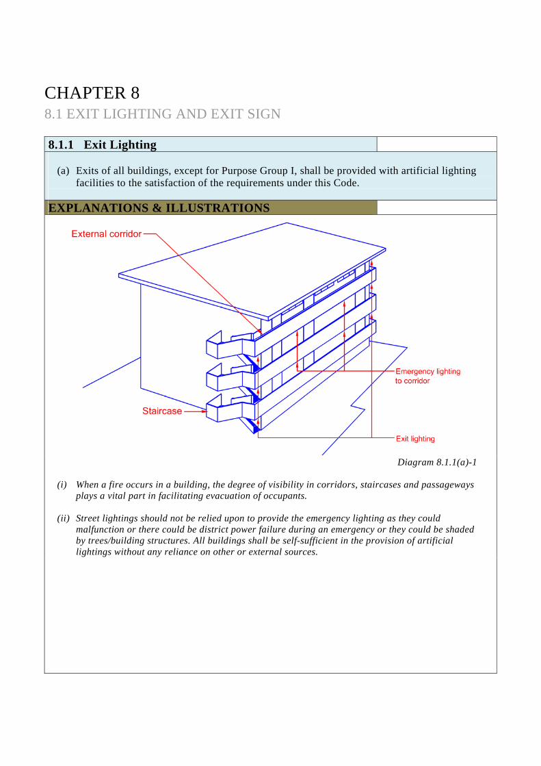
CHAPTER 8 8.1 EXIT LIGHTING AND EXIT SIGN 8.1.1 Exit Lighting
(a) Exits of all buildings, except for Purpose Group I, shall be provided with artificial lighting
facilities to the satisfaction of the requirements under this Code.
EXPLANATIONS & ILLUSTRATIONS
Diagram 8.1.1(a)-1
(i) When a fire occurs in a building, the degree of visibility in corridors, staircases and passageways plays a vital part in facilitating evacuation of occupants.
(ii) Street lightings should not be relied upon to provide the emergency lighting as they could malfunction or there could be district power failure during an emergency or they could be shaded by trees/building structures. All buildings shall be self-sufficient in the provision of artificial lightings without any reliance on other or external sources.
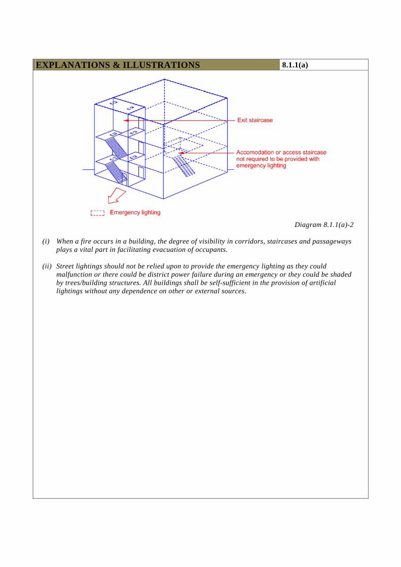
EXPLANATIONS & ILLUSTRATIONS 8.1.1(a)
Diagram 8.1.1(a)-2
(i) When a fire occurs in a building, the degree of visibility in corridors, staircases and passageways plays a vital part in facilitating evacuation of occupants.
(ii) Street lightings should not be relied upon to provide the emergency lighting as they could malfunction or there could be district power failure during an emergency or they could be shaded by trees/building structures. All buildings shall be self-sufficient in the provision of artificial lightings without any dependence on other or external sources.
(b) The minimum illuminance to be provided for all exits and the spacing for luminaires shall be
in accordance with the requirements in SS 563 Code of Practice for the Installation and Maintenance of Emergency Evacuation Lighting and Power Supply Systems in Buildings.
(c) The delay between the failure of the electrical supply to normal lighting and the energization
of the exit lighting shall not exceed 1 second.
EXPLANATIONS & ILLUSTRATIONS 8.1.1
No illustration. SS.563 requires that horizontal illuminance in the centre line of any escape route shall not be less than 0.5 lux, measured at the floor, for minimum duration of 1 hour. The positioning of lighting shall be so arranged that the failure of any single lighting unit, such as the burning out of a bulb, will not leave any area in darkness. Exit areas, such as exit staircases, internal and external exit passageways, are critical areas, there shall be no interruption of illumination exceeding 1 second during the changeover from one energy source to another. This would help ensure the occupants to see their way for example, down the exit staircases without fear of tripping. For ease of reference, the value of 1 foot candle is equivalent to 10 lux, measured at the floor.
CHAPTER 8 8.1 EXIT LIGHTING AND EXIT SIGN 8.1.2 Emergency lighting for corridors and lobbies
(a) Emergency lighting shall be provided in all corridors and lobbies of all buildings except
Purpose Group I. (b) The minimum level of illuminance, the spacing of luminaires and the maximum delay for
emergency lighting required in this Clause shall be the same as that for the exit lighting.
EXPLANATIONS & ILLUSTRATIONS
No illustration. The requirements for provision of emergency lighting for corridors and lobbies in respect of: min. level of luminance;
spacing of luminaires; and
delay (1 second) for the emergency lighting are similar to Clause 8.1.1.
Corridors and lobbies, including routes of escape, smoke stop lobbies, common lobbies, are required to have min. 0.5 lux, measured at the floor, for minimum duration of 1 hour, notwithstanding that residents may be presumed to be familiar with exit facilities by reason of regular usage of such facilities. The emergency lighting system shall be so arranged to provide the required illumination by means of standby generator set upon failure of public utility supply. The changeover from one energy source to another shall not incur a delay of more than 15 seconds. This is considered a reasonable short time for the generating plant to start. However, where battery packs are used for emergency power, they must be the type that will automatically be kept charged and be able to perform for a minimum duration of 1 hour.

CHAPTER 8 8.1 EXIT LIGHTING AND EXIT SIGN 8.1.3 Emergency Lighting for Occupied Areas
(a) For all buildings except Purpose Group I or II, emergency lighting shall be provided in the
occupied areas following the guidelines below:
(i) along paths leading to corridors, lobbies and exits in all occupied areas where the direct distance from the entry point of the corridor, lobby or exit to the furthest point in the area concerned exceeds 13m; or
(ii) over the whole of such area if there are no explicit paths leading to corridors, lobbies
and exits.
EXPLANATIONS & ILLUSTRATIONS
Diagram 8.1.3(a)(i)
Room having a direct distance > 13m and designed with defined escape path shall be provided with emergency lighting.
EXPLANATIONS & ILLUSTRATIONS 8.1.3(a)
.
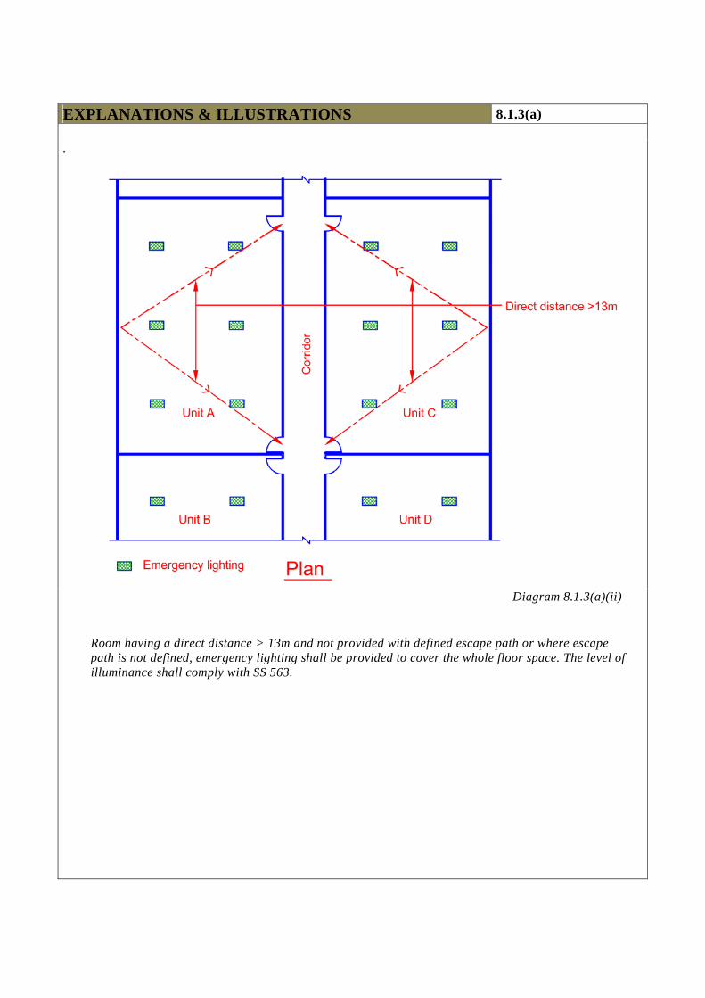
Diagram 8.1.3(a)(ii)
Room having a direct distance > 13m and not provided with defined escape path or where escape path is not defined, emergency lighting shall be provided to cover the whole floor space. The level of illuminance shall comply with SS 563.
(b) Notwithstanding the requirements in (a) above, emergency lighting shall be provided in the
following locations: (i) Lift cars as stipulated in this Code;
(ii) Fire command centres; (iii) Generator rooms; (iv) Basement car parks; (v) Fire pump rooms; (vi) Areas of refuge within the same building.
(c) The minimum level of illuminance shall comply with the requirements in SS 563.
(d) The delay between the failure of the electrical supply to normal lighting and the energization of the emergency lighting for occupied areas shall not exceed 15 seconds.
EXPLANATIONS & ILLUSTRATIONS 8.1.3
No illustration. Emergency lighting is required to be provided to lift car, generator rooms & fire pump rooms to enable maintenance personnel to evacuate safely in times of emergency. The emergency lighting would help fire-fighters if there is a need to gain access into any of these rooms or spaces. Basement car parks are also required to be provided with emergency lighting regardless of the floor area. It would help to lead public to the nearest exit escape routes. Car lighting cannot be taken and relied upon as emergency lighting.
CHAPTER 8 8.1 EXIT LIGHTING AND EXIT SIGN 8.1.4 Emergency lighting for fire-fighting facilities
(a) Fire alarm panels, fire alarm call points and fire-fighting equipment shall be adequately
illuminated at all times so that they can be readily located. (b) The minimum level of illuminance shall comply with the requirements in SS 563. (c) The delay between the failure of the electrical supply to normal lighting and the energization
of the emergency lighting for fire-fighting facilities shall not exceed 15 seconds.
EXPLANATIONS & ILLUSTRATIONS
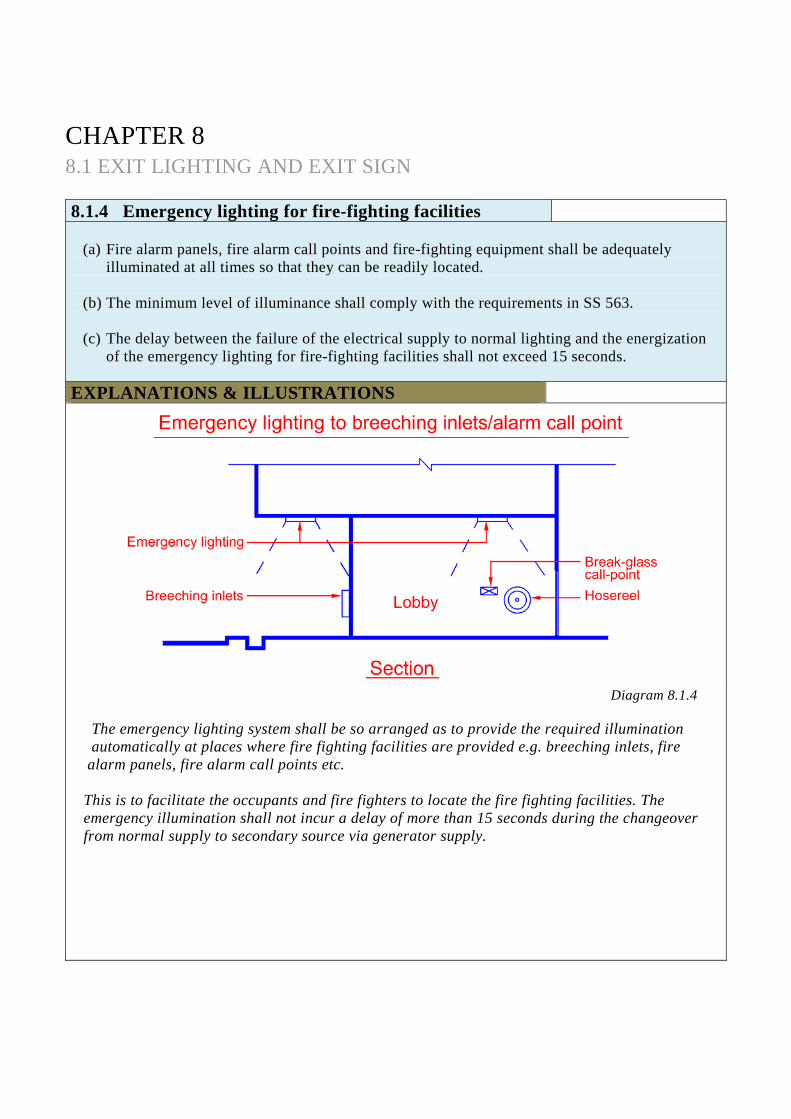
Diagram 8.1.4
The emergency lighting system shall be so arranged as to provide the required illumination automatically at places where fire fighting facilities are provided e.g. breeching inlets, fire alarm panels, fire alarm call points etc.
This is to facilitate the occupants and fire fighters to locate the fire fighting facilities. The emergency illumination shall not incur a delay of more than 15 seconds during the changeover from normal supply to secondary source via generator supply.
CHAPTER 8 8.1 EXIT LIGHTING AND EXIT SIGN 8.1.5 Secondary source of power supply
(a) The delay for energization of the exit and emergency lighting systems between normal
supply and the secondary source shall be as stipulated in the relevant clauses. (b) Duration of the secondary source of power supply shall comply with the requirements in
SS 563. (c) Location, arrangement and control, installation of electrical wiring of the secondary
source of supply, be it in the form of battery, standby generator, inverter or other accepted equipment, shall comply with the requirements in SS 563.
EXPLANATIONS & ILLUSTRATIONS
No illustration. (i) Where maintenance of illumination depends upon changing from normal power supply to secondary
source via generator sets, there should be minimal delay during the switchover, which should not exceed 15 seconds;
(ii) The emergency lighting system shall be capable of maintaining a supply of at least 1 hour, long enough for evacuation of occupants and to serve the initial stage of fire fighting;
(iii) Generally, the time for changeover should not exceed 15 seconds for emergency lighting to be provided at occupied areas and at places where immediate visibility is not essential. As for critical areas such as exit points and along defined exit routes, the minimum level of lighting must be available at all times so that occupants would not panic when making their escape.
CHAPTER 8 8.1 EXIT LIGHTING AND EXIT SIGN 8.1.6 Luminaire
All exit and emergency luminaires required by this Code shall be of approved type as specified in SS 563.
EXPLANATIONS & ILLUSTRATIONS
No illustration. Besides complying with SS 563, all exit and emergency luminaires shall be listed under a recognized certification body.
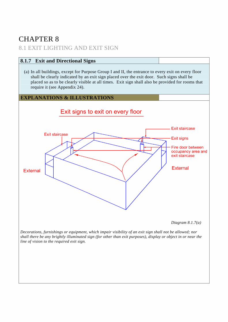
CHAPTER 8 8.1 EXIT LIGHTING AND EXIT SIGN 8.1.7 Exit and Directional Signs
(a) In all buildings, except for Purpose Group I and II, the entrance to every exit on every floor
shall be clearly indicated by an exit sign placed over the exit door. Such signs shall be placed so as to be clearly visible at all times. Exit sign shall also be provided for rooms that require it (see Appendix 24).
EXPLANATIONS & ILLUSTRATIONS
Diagram 8.1.7(a)
Decorations, furnishings or equipment, which impair visibility of an exit sign shall not be allowed; nor shall there be any brightly illuminated sign (for other than exit purposes), display or object in or near the line of vision to the required exit sign.
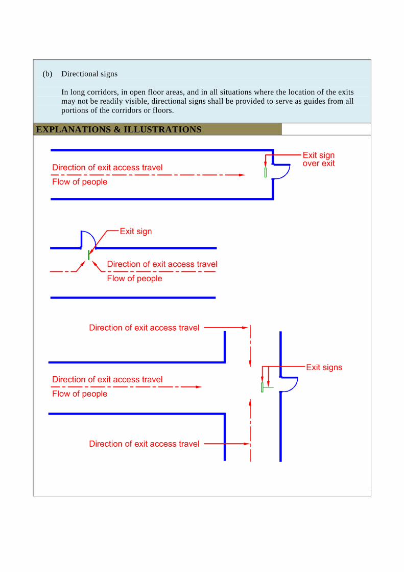
(b) Directional signs
In long corridors, in open floor areas, and in all situations where the location of the exits may not be readily visible, directional signs shall be provided to serve as guides from all portions of the corridors or floors.
EXPLANATIONS & ILLUSTRATIONS
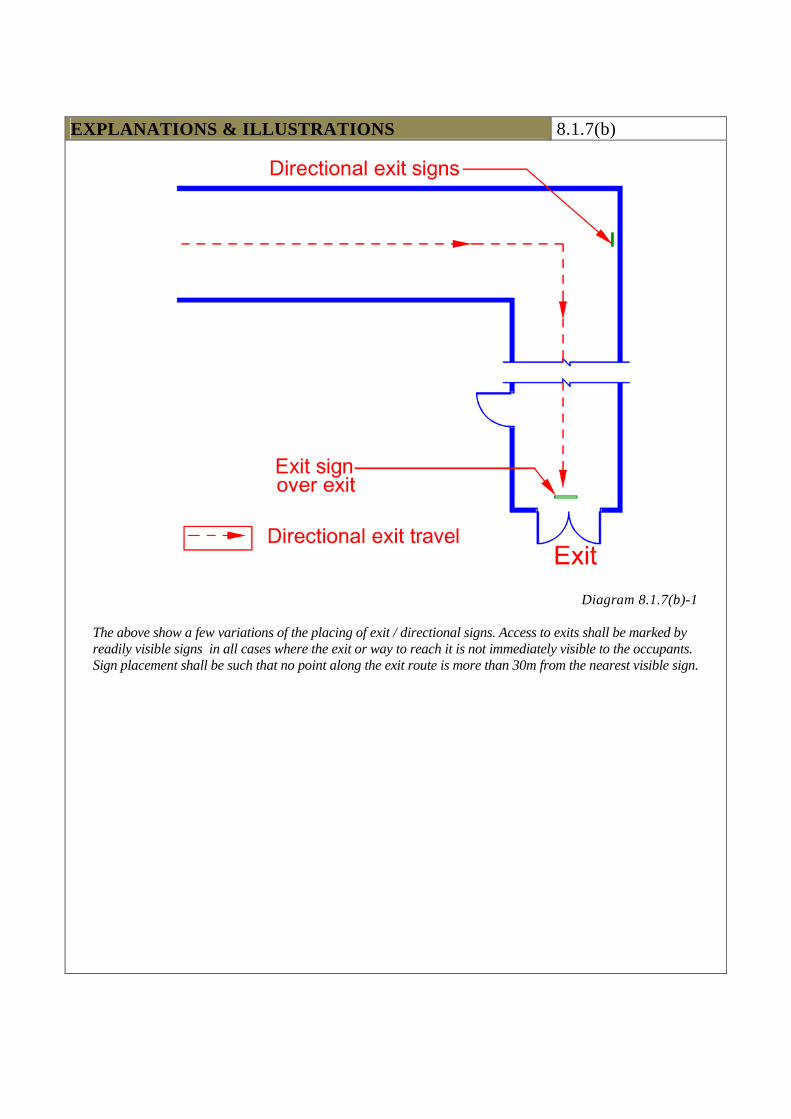
EXPLANATIONS & ILLUSTRATIONS 8.1.7(b)
Diagram 8.1.7(b)-1
The above show a few variations of the placing of exit / directional signs. Access to exits shall be marked by readily visible signs in all cases where the exit or way to reach it is not immediately visible to the occupants. Sign placement shall be such that no point along the exit route is more than 30m from the nearest visible sign.
EXPLANATIONS & ILLUSTRATIONS 8.1.7(b)
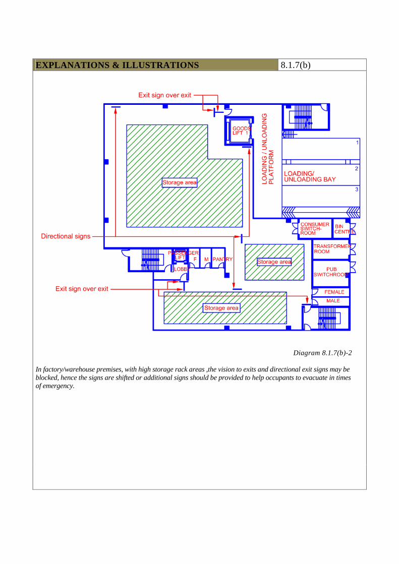
Diagram 8.1.7(b)-2
In factory/warehouse premises, with high storage rack areas ,the vision to exits and directional exit signs may be blocked, hence the signs are shifted or additional signs should be provided to help occupants to evacuate in times of emergency.
EXPLANATIONS & ILLUSTRATIONS 8.1.7(b)
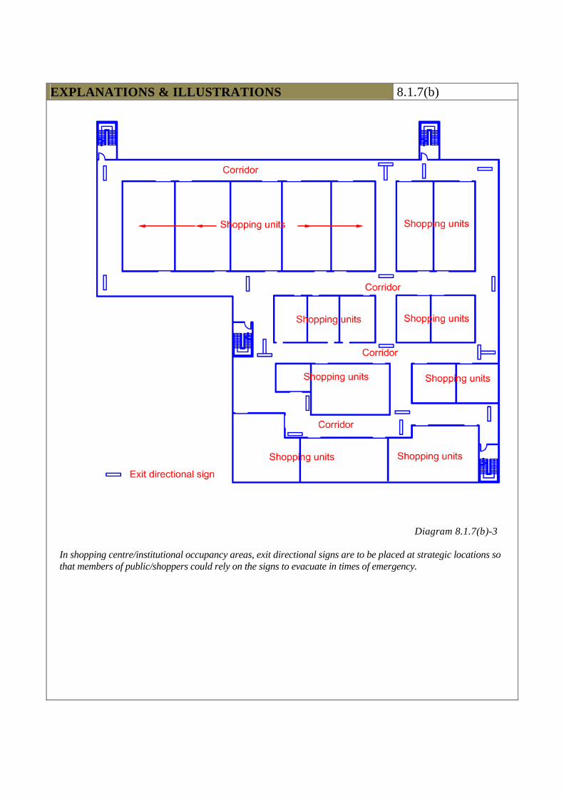
Diagram 8.1.7(b)-3
In shopping centre/institutional occupancy areas, exit directional signs are to be placed at strategic locations so that members of public/shoppers could rely on the signs to evacuate in times of emergency.
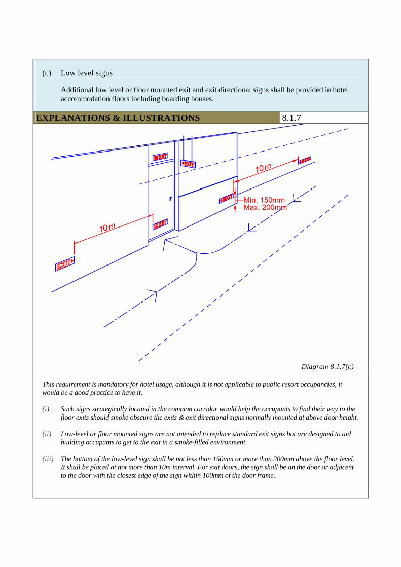
(c) Low level signs
Additional low level or floor mounted exit and exit directional signs shall be provided in hotel accommodation floors including boarding houses.
EXPLANATIONS & ILLUSTRATIONS 8.1.7
Diagram 8.1.7(c)
This requirement is mandatory for hotel usage, although it is not applicable to public resort occupancies, it would be a good practice to have it. (i) Such signs strategically located in the common corridor would help the occupants to find their way to the
floor exits should smoke obscure the exits & exit directional signs normally mounted at above door height.
(ii) Low-level or floor mounted signs are not intended to replace standard exit signs but are designed to aid building occupants to get to the exit in a smoke-filled environment.
(iii) The bottom of the low-level sign shall be not less than 150mm or more than 200mm above the floor level. It shall be placed at not more than 10m interval. For exit doors, the sign shall be on the door or adjacent to the door with the closest edge of the sign within 100mm of the door frame.

(d) Where the Relevant Authority has allowed under subclause 2.3.5(d) upper storey staircase to be
continuous with that serving the basement, appropriate signages, including pictorials shall be placed at strategic location inside the staircase to direct occupants out of the building in times of emergency.
EXPLANATIONS & ILLUSTRATIONS 8.1.7
Applicable only if staircase serves 4 storeys (including basement) or less and entry into the staircase from the basement is through a 1 hour fire rated door.
Diagram 8.1.7(d)-1
This can be done by placing a physical barrier to prevent occupants from continuing below the level of exit discharge into the basement. This helps to warn occupants in the staircase enclosure that they are on the level of exit discharge.
(i) Clause 2.3.5(d) allows upper storey staircase to be continuous with that serving the basement,
which is naturally ventilated.
(ii) To prevent occupants exiting continuously from upper storeys into the basement floor during an emergency, a physical barrier in the form of a door or a gate (as shown above) could be provided across the staircase landing at ground level to separate the discharge route of upper storeys from the basement staircase.
(iii) In addition, appropriate signages should be provided inside the staircase enclosure to direct occupants out of the building at ground level.
EXPLANATIONS & ILLUSTRATIONS 8.1.7(d)
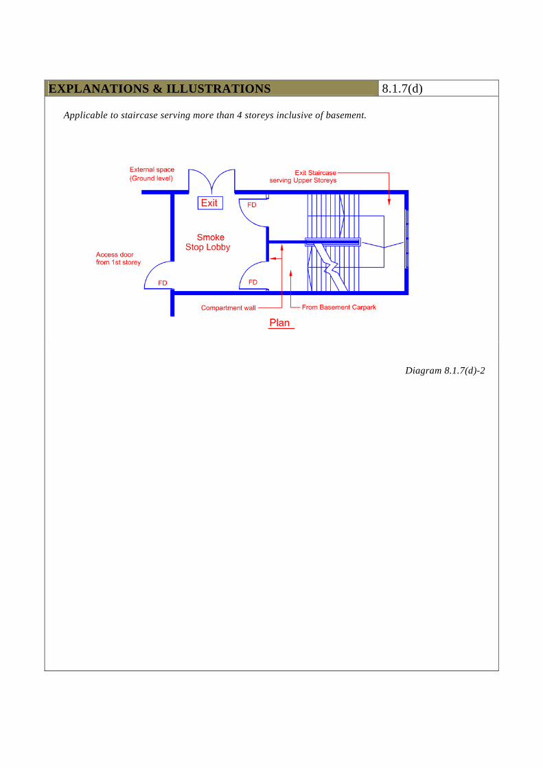
Applicable to staircase serving more than 4 storeys inclusive of basement.
Diagram 8.1.7(d)-2

(e) The legends, dimensions, design and installation of the exit signs and directional signs
shall comply with SS 563.
EXPLANATIONS & ILLUSTRATIONS 8.1.7
No illustration. All exit and emergency illuminaires should be of the approved type by a recognised certification body
(f) Self-illuminating exit signs
Self-illuminating exit and directional signs with letters in green and powered by radioactive material are allowed for use in buildings, provided the signs comply with BS 5499 Part 2, SS 508 and SS 563 under sub-clause 8.1.7(e). With respect to the design of signage, either graphic or text is acceptable.
EXPLANATIONS & ILLUSTRATIONS 8.1.7
No illustration BS 5499 Part 2 has since been withdrawn without replacement. Self-illuminating exit and directional signs powered by radioactive materials shall comply and be tested to the testing standard UL 924 in lieu of BS 5499 Part 2, and suppliers shall produce the certificate of compliance from UL, subject to the Relevant Authority’s consent.
(g) Where the direction of travel to exit discharge is upward, the staircase signage required
under Cl.2.3.1 (b) shall comply with SS 508 – Specification for Fire Safety Signs
EXPLANATIONS & ILLUSTRATIONS 8.1.7
No illustration.
CHAPTER 8 8.2 VOICE COMMUNICATION SYSTEM AND FIRE
COMMAND CENTRE 8.2.1 System requirements
(a) One-way emergency communication system and a fire command centre shall be provided as
follows: (i) For all large buildings under Purpose Groups III (not applicable to primary school,
secondary school and junior colleges), IV, V, VI, VII & VIII with gross floor area greater than 5000 m² or having a total occupant load exceeding 1000 persons; or
(ii) For all buildings belonging to Purpose Groups III, IV, V, VI, VII, and VIII of more than 24m in habitable height.
EXPLANATIONS & ILLUSTRATIONS
No illustration. During fire emergency, the one-way emergency communication system will be used to notify occupants in the building. Under phase evacuation, occupants will be advised to relocate to ‘Safe area of refuge’ in which to wait out the fire. Occupants could also be advised to evacuate the building during fire emergency. In phase evacuation, communication with these people can be maintained to prevent panic and to allow further relocation, if necessary. The one-way emergency voice communication system shall consist of microphone input, selector switches, amplifiers and remote loudspeakers to perform the functions specified. Loud speakers operated from the Fire Command Centre shall be of sufficient number and appropriate design to provide effective voice communication to the following areas : (a) all habitable rooms;
(b) all basement floor areas;
(c) all escape staircases;
(d) all staircase lobbies and lift lobbies forming parts of the means of escape;
(e) the main entrance;
(f) all corridors leading to exits;
(g) all service areas where people may be working;
(h) all areas of refuge;
(i) all assembly areas;
(j) all patients accommodation floors, hotel bedroom floors etc
(k) all other areas as may be required by SCDF(FSSD).
(iii) Exception
For hotel or health care buildings of less than 24m in habitable height, gross floor area not greater than 5000m² and total occupant load not exceeding 1,000 persons, an ordinary public address system shall be provided. However, Fire Command Centre is not required. Loudspeakers for the ordinary public address system shall be provided in every lift lobby, staircase enclosure and other strategic positions within audible distance of all parts of all storeys throughout the building.
EXPLANATIONS & ILLUSTRATIONS 8.2.1(a)
To address the concerns of transient guests and sleeping risk in hotels, boarding houses and the like which are less than 24m in habitable height, an ordinary public address system shall be provided to effect early and orderly evacuation of occupants in times of emergency. The following shall be provided : The ordinary public address system shall consist of the microphone input, selector switches and remote loudspeakers to perform the functions specified. Loud speakers shall be of sufficient number and appropriate design to provide effective voice communication to the following areas : (a) all habitable rooms;
(b) all basement floor areas;
(c) all escape staircases;
(d) all staircase lobbies and lift lobbies forming parts of the means of escape;
(e) the main entrance;
(f) all corridors leading to exits;
(g) all service areas where people may be working;
(h) all areas of refuge;
(i) all assembly areas;
(j) all patients’ accommodation floors, hotel bedroom floors etc;
(k) all other areas as may be required by SCDF (FSSD).
(b) Two-way emergency communication system shall be provided between the Fire Command
Centre, under sub-clauses 8.2.1(a), (i) and (ii) above, and the following area:
(i) every fire-fighting lobby, including 1ststorey; (ii) all fire-fighting related mechanical equipment rooms inclusive of sprinkler pump
room, wet rising main pump room, hose reel pump room, switch rooms and generator rooms;
(iii) all rooms housing smoke control equipment; (iv) all lift machine rooms; (v) fire lift;
Where the lift car is equipped with built-in intercom system that complies with clause 9 of SS 546, the two-way communication system can be exempted.
(vi) each area of refuge; and (vii) air-handling control rooms.
Where AHU can be remotely monitored and controlled at the Fire Command Centre, and cannot be by-passed locally, and the electrical cabling between AHU rooms and FCC are fire rated, the two-way communication system can be exempted.
EXPLANATIONS & ILLUSTRATIONS 8.2.1
No illustration. The two-way communication system shall consist of the main telephone handset and selector switches at the control console located in the Fire Command Centre and the other remote handset installed at various locations as mentioned in the above sub-clause b(i) to (vii). In general, at least one emergency handset shall be located on each floor. When a floor is divided into two or more fire-isolated zones used as areas of refuge for one another, each zone shall be provided with a handset. The criteria to be considered in determining the position of each handset shall be such that, wherever possible, the handset is near the protected staircase or near the central position of the zone covered by it, and as remote as possible from the nearest alarm sounding device. In view of the adequacy of the lift intercom system, SCDF(FSSD) will accept the lift intercom system in-lieu of the handset provided it complies with SS 546 on ‘Installation and Power Supply’.
(c) For building of mixed commercial cum residential usage, the requirements of sub-clauses
a(ii) of this clause shall be applicable provided that:
(i) where the commercial component of the building occupies only the lower portion of the building and is separated from the residential occupancies, then for the purpose of compliance with the said requirements, the measurement of habitable height shall be taken to that part of the commercial component of the building; and
(ii) where a commercial component of the building is located above any residential
occupancies, the provisions of a(ii) shall be applicable if the habitable height of the building exceeds 24m.
EXPLANATIONS & ILLUSTRATIONS 8.2.1
No illustration.
CHAPTER 8 8.2 VOICE COMMUNICATION SYSTEM AND FIRE
COMMAND CENTRE 8.2.2
Where a one-way or two-way emergency communication system is required by this code, it shall comply with the requirements stipulated in SS 546: Code of Practice for Emergency Voice Communication Systems in Buildings.
EXPLANATIONS & ILLUSTRATIONS
No illustration.
CHAPTER 8 8.2 VOICE COMMUNICATION SYSTEM AND FIRE
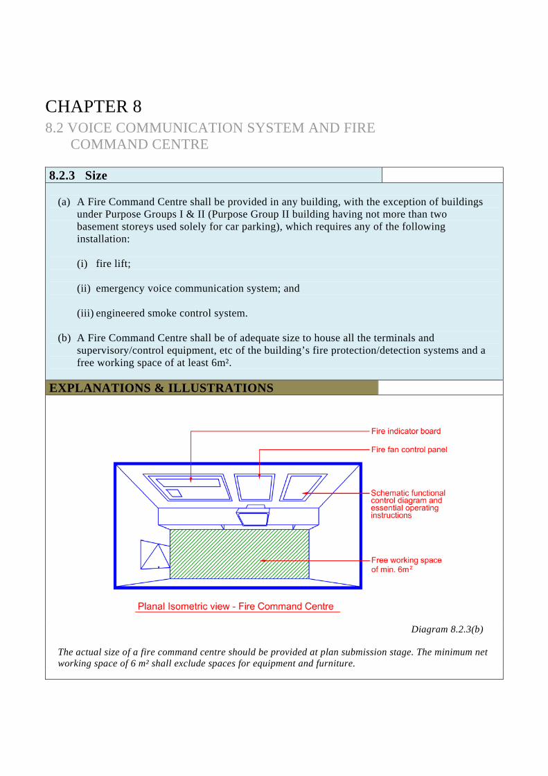
COMMAND CENTRE 8.2.3 Size
(a) A Fire Command Centre shall be provided in any building, with the exception of buildings
under Purpose Groups I & II (Purpose Group II building having not more than two basement storeys used solely for car parking), which requires any of the following installation:
(i) fire lift; (ii) emergency voice communication system; and (iii) engineered smoke control system.
(b) A Fire Command Centre shall be of adequate size to house all the terminals and
supervisory/control equipment, etc of the building’s fire protection/detection systems and a free working space of at least 6m².
EXPLANATIONS & ILLUSTRATIONS
Diagram 8.2.3(b)
The actual size of a fire command centre should be provided at plan submission stage. The minimum net working space of 6 m² shall exclude spaces for equipment and furniture.
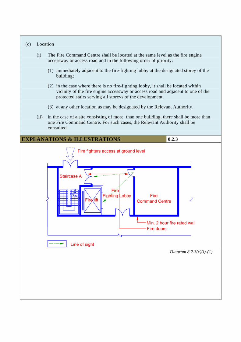
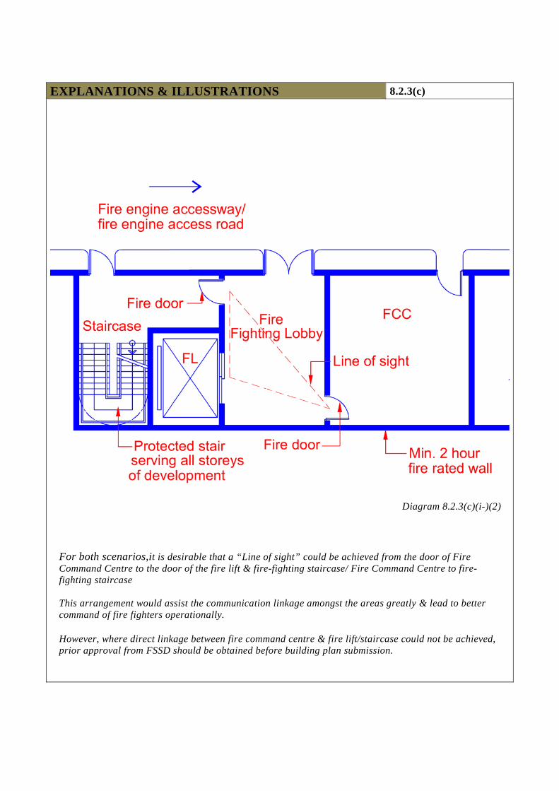
(c) Location
(i) The Fire Command Centre shall be located at the same level as the fire engine
accessway or access road and in the following order of priority:
(1) immediately adjacent to the fire-fighting lobby at the designated storey of the building;
(2) in the case where there is no fire-fighting lobby, it shall be located within
vicinity of the fire engine accessway or access road and adjacent to one of the protected stairs serving all storeys of the development.
(3) at any other location as may be designated by the Relevant Authority.
(ii) in the case of a site consisting of more than one building, there shall be more than
one Fire Command Centre. For such cases, the Relevant Authority shall be consulted.
EXPLANATIONS & ILLUSTRATIONS 8.2.3
Diagram 8.2.3(c)(i)-(1)
EXPLANATIONS & ILLUSTRATIONS 8.2.3(c)
Diagram 8.2.3(c)(i-)(2)
For both scenarios,it is desirable that a “Line of sight” could be achieved from the door of Fire Command Centre to the door of the fire lift & fire-fighting staircase/ Fire Command Centre to fire-fighting staircase This arrangement would assist the communication linkage amongst the areas greatly & lead to better command of fire fighters operationally. However, where direct linkage between fire command centre & fire lift/staircase could not be achieved, prior approval from FSSD should be obtained before building plan submission.
(d) The construction of enclosure, facilities and lighting of a Fire Command Centre shall
comply with the SS 546: Code of Practice for Emergency Voice Communication Systems in Buildings.
EXPLANATIONS & ILLUSTRATIONS 8.2.3
No illustration.
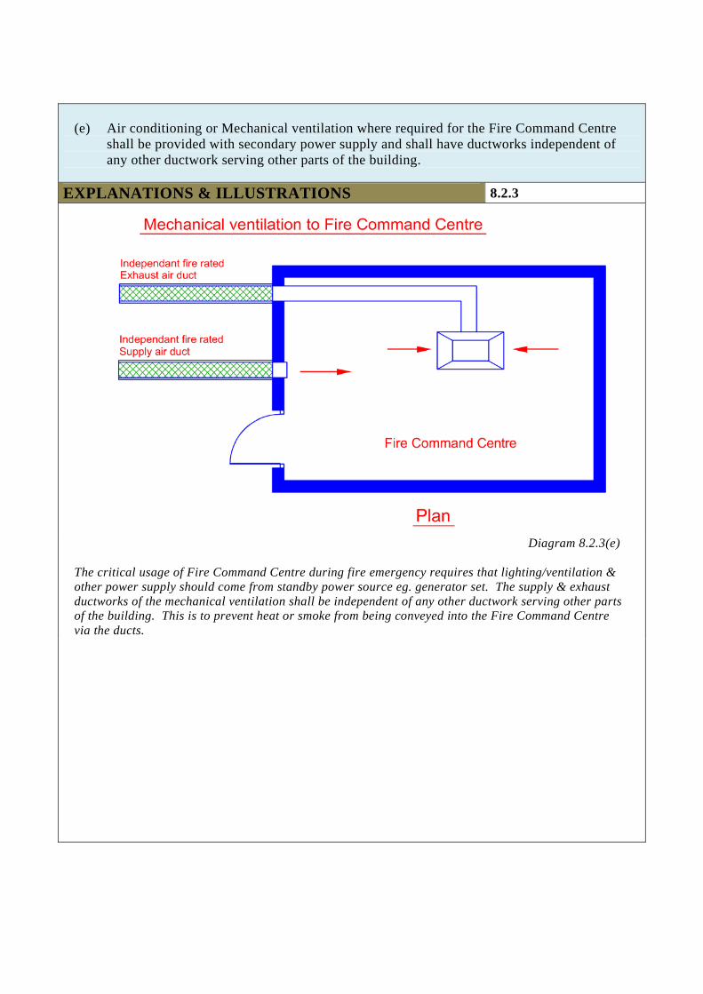
(e) Air conditioning or Mechanical ventilation where required for the Fire Command Centre
shall be provided with secondary power supply and shall have ductworks independent of any other ductwork serving other parts of the building.
EXPLANATIONS & ILLUSTRATIONS 8.2.3
Diagram 8.2.3(e)
The critical usage of Fire Command Centre during fire emergency requires that lighting/ventilation & other power supply should come from standby power source eg. generator set. The supply & exhaust ductworks of the mechanical ventilation shall be independent of any other ductwork serving other parts of the building. This is to prevent heat or smoke from being conveyed into the Fire Command Centre via the ducts.
CHAPTER 8 8.2 VOICE COMMUNICATION SYSTEM AND FIRE
COMMAND CENTRE 8.2.4 Two-way communication system
All multi-level basements of buildings under Purpose Group II to VIII are required to be provided with two-way emergency communication system between the Fire Command Centre and the following areas:
(a) Every fire-fighting lobby, including 1st storey. In building comprising 2, 3 or 4 basements, one of the smoke-stop lobbies shall be designated as a fire-fighting lobby;
(b) All fire-fighting related mechanical equipment rooms, inclusive of sprinkler pump room, wet rising main pump room, hosereel pump, switch rooms, generator rooms, and lift machine room;
(c) All rooms housing smoke control equipment; (d) Fire lift;
Where the lift car is equipped with built-in intercom system that complies with clause 9 of SS 546, the two-way communication system can be exempted.
(e) Each area of refuge; and (f) Air-handling control rooms.
Where AHU can be remotely monitored and controlled at the Fire Command Centre, and cannot be by-passed locally, and the electrical cabling between AHU rooms and FCC are fire rated, the two-way communication system can be exempted.
Exception:
(i) Single-level basement, irrespective of its usage of building under Purpose Groups II to VIII and basements of building of Purpose Group I are not required to be provided with two-way emergency communication.
(ii) Multi-level basements of building under Purpose Group II are not required to be provided with two-way emergency communication system, provided the basements are used solely for car parking and not exceeding two basement storeys in depth.
EXPLANATIONS & ILLUSTRATIONS
No illustration. The above requirement would be applicable to buildings having any basements greater than a depth of 9m from the averaged ground level outside the building. This is to complement the need to provide fire lift to serve the basement storeys under Cl.6.6.3(a) of the current Fire Code. In view of the adequacy of the lift intercom system, SCDF (FSSD) will accept the lift intercom system in-lieu of the handset provided it complies with SS 546 on ‘Installation and Power Supply’.