chapter 8 durability/service life of structural …...chapter 8 durability/service life of...
TRANSCRIPT

Chapter 8
Durability/Service Life of
Structural Lightweight Concrete
April 2007
Expanded Shale, Clay & Slate Institute (ESCSI)
2225 E. Murray Holladay Rd, Suite 102
Salt Lake City, Utah 84117
(801) 272-7070 Fax: (801) 272-3377
[email protected] www.escsi.org

8-1
CHAPTER 8
8.0 Historical Performance
8.1 Resistance to Freezing and Thawing
8.2 Resistance to Sulfate Attack
8.3 Resistance to Alkali-Silica Reaction
8.4 Carbonation
Measurements of Carbonation Depth in Mature Marine Structures
8.5 Influence of Concrete Zone on Durability
Contact Zone of Mature Concrete Subjected to Severe Exposure
Related Studies on the Contact Zone
Implications of Contact Zone on Failure Mechanisms
8.6 Long-Term Performance
Treat Island
8.7 Design for 100 Year Life

8-2
Chapter 8 Durability/Service Life
8.0 Historical Performance
Lightweight Concrete Ships
The first structural application using rotary kiln-produced lightweight concrete
was the USS Selma, which was launched in 1919 (Holm 1980a). This 7,500 ton
ship now partially submerged and resting on the ground in Galveston Harbor and
declared a National Monument has been exposed to seawater continuously. In
many areas it was damaged – when run onto a rock breakwater at Tampico Bay,
Mexico, and as a result of hard berthing and extensive physical damage when the
steel and equipment was salvaged from the ship. Much of the concrete below the
waterline both inside and outside the hull (after the barnacles had been scraped
off) appear to be in an as-cast condition with the form marks still visible.
Figure 8.1. Launching of lightweight concrete ship
USS SELMA in 1919
Several of the Selma’s holds contain water with over 6 ft. (2 m) head above the
surrounding sea, providing ample proof of the low permeability of the concrete.
In many undamaged sections of the ship the 0.5 to 1.2 in. (12 – to 30-mm) cover
has proven surprisingly effective in protecting the reinforcing steel from

8-3
corrosion. The effectiveness of lightweight concrete in protecting the reinforcing
steel was also shown by Sturm, McAskill, et. al. SP-189 ACI. The strength of the
concrete on the Selma was in excess of 4,000 psi (27.6 MPa) at 28 days at a time
when ordinary concrete had a strength of 2,000 psi (13.8 MPa). Cores taken from
the Selma in 1980 had compressive strengths in excess of 8,000 psi (55.2 MPa)
for concrete with a unit weight of about 110 lb/ft³ (1,762 kg/m³). Since the
strength/performance ratio is comparable to what is now commonly referred to as
high-performance concrete; it’s impressive that structural lightweight concrete at
110 lb/ft³ had over 70 years head start for high-performance concrete with a much
better strength/to density ratio.
Samples of concrete taken from the Selma below the waterline were examined in
a scanning electron microscope. It was noted that, other than in a region near the
aggregate-cement paste interface, there was very little evidence of aggregate
vesicules becoming filled with marine or hydration products. Also, the aggregate-
cement paste interface was of exceptional quality, with the transition between
hydration product and aggregate in most instances difficult to discern, which is
not the case for normal density concrete (Holm, Bremner, and Newman 1984)
(Sturm, et.al. 1999), with normal density concrete, extensive microcracking
typically occurs at the aggregate-cement paste interface. The hydration products
are normally of inferior quality at the interface as well. In terms of validating
long-term performance of current lightweight concrete projects, the aggregate
from the Selma had a microstructure that was identical to aggregates produced by
a modern rotary kiln; long-term good performance can be expected from current
ESCS production, provided that changes to the portland cement are not a factor.
8-4
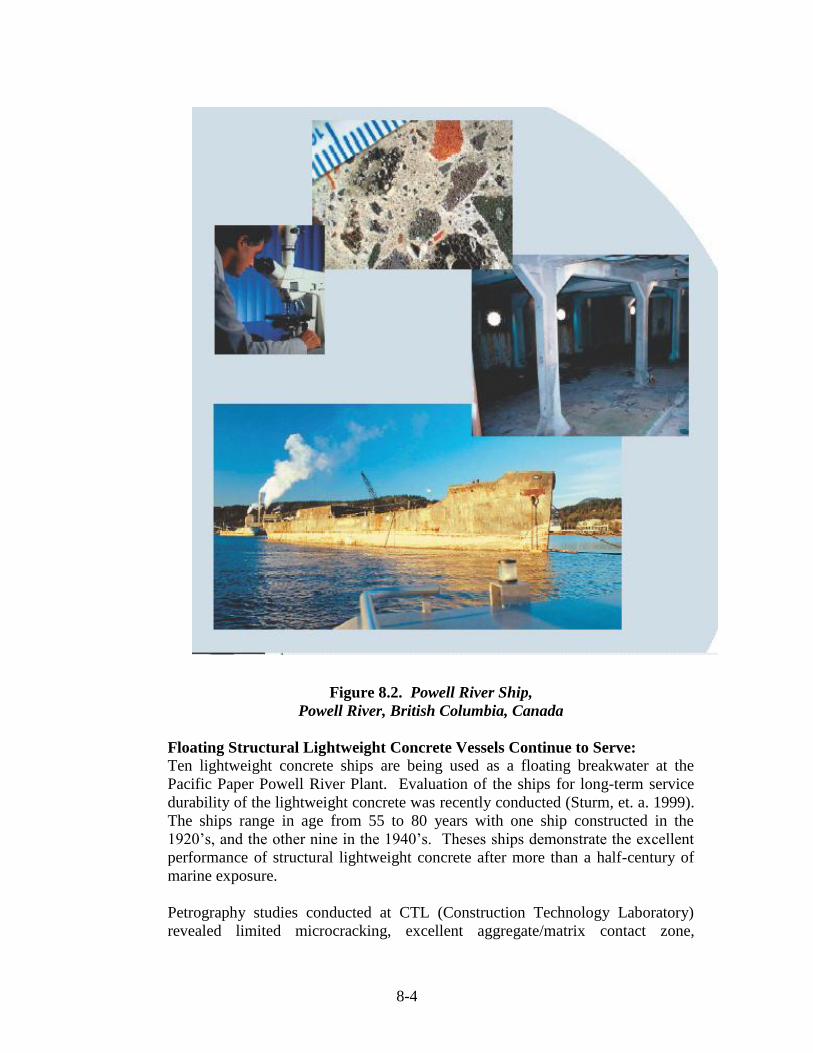
Figure 8.2. Powell River Ship,
Powell River, British Columbia, Canada
Floating Structural Lightweight Concrete Vessels Continue to Serve:
Ten lightweight concrete ships are being used as a floating breakwater at the
Pacific Paper Powell River Plant. Evaluation of the ships for long-term service
durability of the lightweight concrete was recently conducted (Sturm, et. a. 1999).
The ships range in age from 55 to 80 years with one ship constructed in the
1920’s, and the other nine in the 1940’s. Theses ships demonstrate the excellent
performance of structural lightweight concrete after more than a half-century of
marine exposure.
Petrography studies conducted at CTL (Construction Technology Laboratory)
revealed limited microcracking, excellent aggregate/matrix contact zone,

8-5
complete hydration of the cement, and insignificant damage due to freezing and
thawing. This microscopic examination clearly showed evidence of continued
hydration and development of the cement matrix. This continued maturation of
the concrete has contributed to the development of compressive strengths up to
8700 psi in the ships’ hulls well beyond the minimum design strength (5000 psi)
of the concrete. Concrete densities range from 106 lb/ft³ to 130 lb/ft³.
According to the inspectors’ report, the “paste-aggregate bond is consistently
excellent in all the examined concrete specimens, in part attributed to mostly
beneficial reactions along the paste-aggregate interface. Overall, the
manufactured lightweight concrete used in the construction of the ships has
performed exceptionally well in a harsh marine environment.”
8.1 RESISTANCE TO FREEZING AND THAWING
Probably one of the most severe exposure conditions for concrete is in bridge
decks in regions where de-icing agents are used. If concrete freezes at the
beginning of winter and stays frozen until the end of winter, only one (or very
few) cycles of freezing and thawing will have occurred, with little likelihood of
damage until passage of many years. However, severe damage may be caused in
relatively mild climates where many freezing and thawing cycles occur each
season and large amounts of de-icing agents are applied. De-icing chemicals melt
ice and snow and produce water that increases concrete saturation and chloride
concentration. The concrete then freezes again when the temperature drops,
frequently resulting in daily cycles. If salt, and the sand holding the salt, are not
promptly removed, steel corrosion is facilitated. Once corrosion begins, the
concrete cover over the reinforcement starts to spall. The problem is very severe
in the northeastern areas of the United States, making this region a useful location
for comparative studies of the relative performance of lightweight and
normalweight concrete. These areas have had a long history of bare bridge decks,
whereas in Canada it is common to use a waterproof membrane concrete under
the asphalt to prevent ingress of chloride ions into the concrete. A study of
lightweight concrete bridge decks was completed in 1960 (Expanded Shale, Clay
and Slate Institute, ESCSI 1960). Based on published reports in the United States
(FHWA 1985), England and Japan, the performance of lightweight concrete
bridge decks is at least as good as normal density concrete bridges (Brown,
Larsen and Holm 1995).
By 1935, over 34 lightweight concrete bridges had been built in North America,
including nine in Canada (ESCSI- 1960). The good performance of several early
bridges, built before concrete was air entrained, is surprising. The fact that water
reducing admixtures in the 1950’s entrained some air and were used in placing
lightweight concrete might, in part, account for their good long-term performance
(Holm 1983). Another reason for their good performance is that pores within the
lightweight aggregate can act as pressure relief chambers when the hydraulic

8-6
pressure develops as the free water freezes. Crushed porous brick has also been
shown to provide freeze-thaw protection in a similar manner when added to
concrete that was subsequently exposed to freezing and thawing.
For the last several decades it has been common practice to use entrained air in all
lightweight concrete. When freezing and thawing is anticipated, 4 to 8 percent
entrained air contents are recommended in lightweight concrete with a nominal
maximum aggregate size of 3/4" (19.0 mm), and 5 to 9 percent when the nominal
maximum aggregate size is 3/8" (9.5 mm). To achieve an effective air-void
system that will protect the concrete from repeated cycles of saturated freezing
and thawing, it is essential that the air voids be well distributed throughout the
cement paste matrix. Generally, the longest distance from any point in the cement
paste matrix to an entrained air void should be less than 0.2 mm. This can usually
be achieved by using an air-entraining admixture meeting the requirements of
ASTM C 260. In special situations where exposure conditions are severe or
where unusual placing techniques are involved, the actual air-void spacing should
be measured in simulated job site conditions to confirm that an adequate air void
system will be achieved. This is done according to the procedures described in
ASTM C 457.
If not properly protected, concrete made with lightweight aggregates with a high
degree of saturation may be vulnerable to early freezing damage. As with
normalweight, lightweight concrete should be protected from freezing conditions
until it has been cured (time and temperature) in accordance to procedures in ACI
306. This is necessary to allow adequate strength to develop.
8.2 Resistance to Sulfate Attacks
As with normalweight concrete, the ACI 318 code recommendations should be
followed with respect to the level of sulfates in the groundwater, see Table 8.1.
This entails limiting the tricalcium aluminate in the cement, which is the
compound that combines with the sulfates to produce an expansion. Seawater
also contains sulfates, but the presence of chlorides tends to inhibit the expansive
reaction that is characteristic of attack by sulfates from groundwater or soils.

8-7
Table 8.1 Requirements for Concrete Exposed to Sulfate-Containing Solutions from ACI 318 Section 4.3 Sulfate
Exposure
Sulfate
Exposure
Water-Soluble
Sulfate (SO4) in
Soil, percent by
mass
Sulfate (SO4) in
Water, ppm
Cement Type
Maximum
Water
Cementitious
Materials Ratio,
by mass, Normal
Density
Aggregate
Concrete
Minimum f’ct
Normal Density
and lightweight
Aggregate, psi
Negligible 0.00 < SO4 <0.10 0< SO4 <150 --- --- ---
Moderate²
0.10< SO4 <0.20
150< SO4 <1,500
II, IP (MS)
IS (MS), P(MS)
I (PM)(MS),
I(SM)(MS)
0.50
4,000
Severe 0.20< SO4 <2.00 1,500< SO4 <10,000 V 0.45 4,500
Very Severe SO4 >-2.00 SO4 > 10,000 V plus
pozzolan³
0.45 4,500
¹ Lower water-cementitious materials ratio or higher strength may be required for low permeability or for
protection against corrosion of embedded items or freezing and thawing.
² Seawater
³ Pozzolan that has been determined by test or service record to improve sulfate resistance when used in concrete
containing Type V cement.
As with most attacks from the surface, increased impermeability improves
resistance to deterioration. A lower w/cm, increased moist curing, and the use of
air-entrained concrete are desirable. Also, the reduced microcracking in
lightweight concrete and the improved quality of aggregate-to-mortar matrix bond
suggest that the concrete maybe more resistant to sulfate attack.
8.3 Resistance to Alkali-Silica Reaction
Concrete made from either natural lightweight aggregate or manufactured
lightweight aggregate appears not to be adversely affected by any long-term
interaction between silica-rich aggregates and the alkalies in the cement, or from
the ingress of alkalies from natural sources such as seawater (Holm 1980a). In
concrete mixtures that contain reactive normalweight aggregate, replacement of
either reactive or even the nonreactive normalweight aggregate with lightweight
aggregate has been found to significantly reduce deleterious expansions (Bremner
et al. 1998, Boyd 1998) Figure 8.3.

8-8
The heating of the aggregate in a rotary kiln tends to activate the aggregate
surface such that it appears to act as a source of silica to react with the alkalis
from the cement at an early age to counteract any potential long-term disruptive
expansion (Boyd 1998) Figure 8.4. Another factor that enables a porous
aggregate to reduce disruptive expansion is the availability of pores (space) within
the expanded lightweight aggregate for reactive material to precipitate into, in a
benign manner. “The glass phase of expanded clay, shale and slate may be alkali
reactive but expansion of concrete from this cause has not been observed because
any siliceous gels that are generated are accommodated within the abundant air-
filled cavities that characterize the expanded particles,” ASTM C294 “Standard
Descriptive Nomenclature for Constituents of Concrete Aggregates,” section
26.3.5. In Figure 8.3, the beneficial effect of replacing some of the aggregates
with lightweight aggregates on expansion can be seen.
Figure 8.3. Reduction of expansion when lightweight aggregates are used
(Bremner et al. 1998) (Mixture 1 – Nonreactive normalweight fine and coarse
aggregate; Mixture 2 – Reactive normalweight aggregate and nonreactive fine
aggregate; Mixture 3 – Reactive normalweight coarse aggregate and one half of
absolute volume of nonreactive fine aggregate replaced by lightweight fine
aggregate)

8-9
Figure 8.4. Concrete with a precipitation of alkali-rich material
in the pores of lightweight aggregate (Boyd 1998).
In Figure 8.4, precipitation of alkali-rich material in the pores of an expanded
aggregate can be seen in concrete made with a well-known reactive normalweight
coarse aggregate in which some of the nonreactive fine aggregates have been
replaced with lightweight fine aggregates.
8.4 CARBONATION
Carbonation is the reaction in concrete of carbon dioxide from the air with
calcium hydroxide released during the hydration of cement. This reaction
produces calcium carbonate that can diminish the natural protection of steel
reinforcement afforded by the concrete. The very slow rate at which the
carbonation front advances into concrete has been studied in many testing
programs. This section of the reference manual reports on measurements of the
penetration of carbonation into mature, exposed lightweight concrete structures.
Concern for carbonation is predicated on the lowering of the concrete’s alkalinity,
which in turn, removes the protective layer over the reinforcing steel, making it
vulnerable to corrosion. Two primary factors protect the steel from corrosion, an
adequate depth of cover over the top of the reinforcing and a low permeable high
quality concrete.

8-10
Measurements of Carbonation Depth in Mature Marine Structures
Concrete Ships, Cape Charles, VA.
Holm, Bremner, and Vaysburd (1988) reported the results of carbonation
measurements conducted on cores drilled from several concrete ships built during
the 19140’s. The ships were used as breakwaters for a ferry-boat dock in the
Chesapeake Bay at Cape Charles, Virginia. They were constructed with carefully
inspected high-quality concrete made with ESCS fine and coarse lightweight
aggregates and a small volume of natural sand. High-cement contents were used
to achieve compressive strengths in excess of 5,080 psi (35 MPa) at 28 days with
a density of 108 pcf (1m7030 kg/m³) (McLaughlin 1944)•. Despite freezing and
thawing in a marine environment, the hulls and superstructure concretes are in
excellent condition after 5 decades of exposure. The only less-than-satisfactory
performance was observed in some areas of the main decks. These areas
experienced a delamination of the 0.78 in. (20 mm) concrete cover that protected
four layers of large un-deformed reinforcing bars spaced 4 in. (100 mm) on
centers. In retrospect, this failure plane is understandable and should have been
avoided by the use of modern prestressing methods. Cover for hull reinforcing
was specified at 7/8 in. (22 mm), with all other reinforcement protected by only
1/2 in. (13 mm) of cover.
Without exception, the reinforcing steel bars cut by the 18 cores taken were rust
free. Cores that included reinforcing steel were split along an axis parallel to the
plane of the reinforcement. This was done by following the procedures of ASTM
C 496. Visual inspection revealed negligible corrosion when the bar was
removed. After the interface was sprayed with phenolphthalein, the surfaces
stained a vivid red, indicating no carbonation at the steel-concrete interface.
Carbonation depth (as revealed by spraying the freshly fractured surface with a
standard solution of phenolphthalein) averaged 1 mm for specimens taken from
the main deck, was between 0.04 and 0.08 in. (1 and 2 mm) for concretes in
exposed wing walls, and was virtually nonexistent in the hull and bulkheads.
Coring was conducted from the waterline to as much as 16 ft. (5 m) above high
water, and in no instances could carbonation depths greater that 0.08 in (2 mm) be
found. In isolated instances, flexural cracks up to 0.31 in. (8 mm) in depth were
encountered, and these had carbonated in the plane of the crack. The carbonation
did not appear to progress more than 0.004 in. (0.1 mm) perpendicular to the
plane of the crack.

8-11
The result of these tests is given in Table 8.2. The value of Kc is calculated as
follows:
Kc = d
√t
where
Kc = carbonation coefficient
d = carbonation depth (in millimeters) determined by spraying a freshly
exposed surface with phenolphthalein
t = time (in years)
Two primary factors influence the carbonation coefficients. High-quality, low
permeability concrete will inhibit the diffusion of carbon dioxide, and the
concrete with high moisture content will reduce the diffusion rate to that of a gas
through water rather than that of a gas through air.
Table 8.2 Field Measurements of the Depth of Carbonation
Location
Structure and Age
Concrete Data (Strength and Density)
Depth of
Carbonation
mm (in)
Kc
(mm/√ years)
Cape Charles
Virginia
Concrete Ships
> 70 years old
All LWC (35 MPa, 1,730 kg/m³)
(A) Hull bulkhead
(B) Wing-wall
(C) Superstructure deck-top
(D) Superstructure deck-bottom
1 (0.04)
1 (0.04)
1 (0.04)
2 (0.08)
0.2
0.2
0.2
0.3
Annapolis, MD
Chesapeake Bay
Multispan, 4-mile
Bridge, 35 years
All LWC (24 MPa, 1,650 kg/m³)
(A) Top surface, truss span
(B) Bottom surface, truss span
(C) Top surface, approach span
(D) Bottom surface, approach span
1 (0.04)
5 (0.20)
8 (0.31)
13 (0.51)
0.2
0.8
1.4
2.2
Coxsackie, NY
(not over seawater)
N.Y. State Thruway
Interchange bridge,
15 years
Sand LWC (27 MPa, 1760 kg/m³)
(A) Exposed top deck
(B) Bottom surface
5 (0.20)
10 (0.39)
1.3
2.6
Japan Bridges/Viaducts,
19 years
Sand LWC (23 MPa, 1820 kg)
Sand LWC (26 MPa)
16 (0.63)
18 (0.71)
3.7
4.1
All LWC: Lightweight fine and coarse aggregate.
Holm, Bremner, Vaysburd (1988)

8-12
Concrete cores taken from the 35-year-old Chesapeake Bay Bridge revealed
carbonation depths of 0.08 to 0.31 in. (2 to 8 mm) from the top of the bridge deck
and 0.08 to 0.51 in (2 to 13 mm) from the underside of the bridge deck. The
higher carbonation depth on the underside reflects the increased gas diffusion
associated with this drier portion of the bridge. The 1.41 in. (36 mm) asphalt
wearing course appears to have inhibited drying and thus reduced carbonation
depth on top. Physical and mechanical properties have been reported previously
(Holm 1983; Holm, Bremner, and Newman 1984).
Cores drilled with the permission and cooperation of the New York State
Thruway Authority from the 15-year-old exposed deck surface of the Interchange
Bridge at Coxsackie revealed 0.20 in. (5 mm) carbonation depths for the top
surface and 0.39 in. (10 mm) from the bottom. Despite almost 1,000 saltings of
the exposed deck, there was no evidence of corrosion in any of the reinforcing
bars cut by the six cores taken (Holm, Bremner, and Newman 1984).
The results of measurements of carbonation depths on mature marine structures in
North America (shown in Fig. 8.5) are paralleled by data reported by Ohuchi et al.
(1984). These investigators studied the chloride penetration depth of carbonation
and incidence of microcracking in both structural lightweight concrete and
normalweight concrete on the same bridges, aquaducts, and caissons after 19
years of exposure. The high-durability performance of those structures as
measured by the test results of carbonation depths, microcracking, and chloride
penetration profiles Ohuchi et al. (1984) are similar to reports by Khokrin (1973)
who suggested that with regard to other variables (specimen size, media pressure,
and equipment), structural lightweight concrete had equal or lower permeability
than its normalweight counterpart. Khokrin (1973) further reported that the lower
permeability of lightweight concrete was attributed to the elastic compatibility of
the constituents and the enhanced bond between the coarse aggregate and the
matrix. In the Onoda Cement Company tests (Nishi et al. 1980), concretes with
water-cement ratios of 0.55, moist-cured for 28 days when tested at 9 kg/cm²
water pressure had depth of penetration of carbonation 1.38 in (35 mm) for
normalweight concrete and 0.95 in. (24 mm) for lightweight concrete. When
tested with seawater, penetration was 0.59 and 0.47 in. (15 and 12 mm) for
normalweight concrete and lightweight concrete, respectively. The author
suggested that the reason for this behavior was “a layer of dense hardened cement
paste surrounding the particles of artificial lightweight coarse aggregate”.

8-13
Figure 8.5. Measured depth of carbonation (in millimeters)
of exposed lightweight concrete
(from Holm, Bremner, and Vaysburd 1988)
Figure 8.6. Measured depth of carbonation (in millimeters)
of laboratory specimens of lightweight concrete
(from Holm, Bremner, and Vaysburd 1988)
The effect of strength and density and moisture exposure on carbonation depth
can be seen in Fig. 8.6 which covers specimens stored for over 20 years in a
Richmond, VA., laboratory. These widely varying concrete types (normalweight,
sanded lightweight, all lightweight and an insulating type concrete) had been part
of an unrelated investigation into time related density and moisture variations in
non-structural concrete. To develop fracture surfaces without saw cutting, the
prisms were split by techniques similar to the tensile splitting method of ASTM C
496 as described earlier. The results clearly indicate that an increased rate of
carbonation occurs in low strength concrete in a dry environment.
8-14
The U.S. Navy sponsored work by Keeton (1970), who reported the lowest
permeability with high strength lightweight concrete. Bamforth (1987)
incorporated structural lightweight concrete as one of the four concretes tested for
permeability to nitrogen gas at 145 psi (1 MPa) pressure level. The normalweight
concrete specimens included high-strength 13,000 psi (90 MPa) concrete as well
as concretes with a 25-percent fly ash replacement, by mass or volume. The
sanded structural lightweight concrete with a strength of 7,250 psi (50 MPa), and
6-4% air and with a density of 124 lb/ft³ (1,985 kg/m) demonstrated the lowest
water and air permeability of all mixtures tested.
Fully hydrated portland cement paste of low W/C has the potential to form an
essentially impermeable matrix that should render concretes impermeable to the
flow of liquids and gases. In practice, however, this is not the case, as
microcracks form in concrete during the hardening process, as well as later, due to
shrinkage, thermal, and applied stresses. In addition, excess water added to
concrete for easier placing will evaporate, leaving pores and conduits in the
concrete. This is particularly true in exposed concrete decks where concrete has
frequently provided inadequate protection for steel reinforcement.
Mehta (1986) observed that the permeability of a concrete composite is
significantly greater than the permeability of either the continuous matrix system
or the suspended coarse aggregate fraction. This difference is primarily related to
extensive microcracking caused by mismatched concrete components responding
differently to temperature gradients, service load-induced strains, and volume
changes associated with chemical reactions taking place within the concrete. In
addition channels develop in the transition zone surrounding coarse aggregates,
which enable moisture movements. While separations caused by the evaporation
of bleed water adjacent to natural aggregates are frequently visible to the naked
eye, such defects are almost unknown in structural lightweight concrete.
The continuous, high-quality matrix fraction surrounding lightweight aggregate is
the result of several beneficial processes. Khokrin (1973) reported on several
investigations that documented the increased transition zone microhardness due to
pozzolanic reaction developed at the surface of the lightweight aggregate.
Bremner, Holm, and deSouza (1984) conducted measurements of the diffusion of
the silica out of the coarse lightweight aggregate particles into the cement paste
matrix using energy-dispersive X-ray analytical techniques. The results
correlated with Khokrin’s observations that the superior contact zone in structural
lightweight concrete extended approximately 60 μm from the lightweight
aggregate particles into the continuous matrix phase.
In addition, the contact zone in structural lightweight concrete is the interface
between two porous media: the lightweight aggregate particle and the hydrating
cement binder. This porous media interface allows for hygral equilibrium to be
reached between the two phases, thus eliminating weak zones caused by water
concentration. In contrast, the contact zone of normal density concrete is an

8-15
interface between a dense, nonabsorbent component and a water-rich binder. Any
accumulation of water at that interface is subsequently lost during drying, leaving
voids.
Laboratory testing of normalweight concrete indicates that, in the unstressed state,
the permeability of the two concretes is about equal. However, at higher levels of
stress, the lightweight concrete can be loaded to a higher percentage of its
ultimate compressive strength before the microcracking causes a sharp increase in
permeability (Sugiyama, Bremner, and Holm 1996). This laboratory testing fails
to take into account the more aggressive conditions that exist in the field,
particularly at an early age that makes this effect of even greater importance. In
the laboratory, the concrete is maintained at constant temperature, there are no
significant shrinkage restraints, and field-imposed stresses are absent. All of
these issues need to be considered when comparing laboratory and field
conditions. Because of the initial absorption of water by the lightweight
aggregate prior to mixing, this absorbed water can act as water for extended moist
curing. The water tends to wick out from the coarse pores, of the aggregate into
the finer capillary pores in the cement paste, thereby extending moist curing. This
process is referred to as internal curing (As reported by Sugiyama 1999). The
beneficial pozzolanic reaction is effective over a long time. Laboratory testing
that is usually completed in less than a few months may not adequately take this
into account.
8.5 Influence of Contact Zone on Durability
The contact zone is the interface between the lightweight aggregate and the
surrounding mortar matrix where a transition layer of material connects the coarse
aggregate particle with the mortar matrix. Analysis of this linkage layer requires
consideration of more than the adhesion developed at the inter face and should
include the transitional layer that forms between the two phases. Collapse of the
structural integrity of a conglomerate may come from the failure of one of the two
phases, or from a breakdown in the contact zone causing a separation of the still
intact phases. The various mechanisms that act to maintain continuity, or that
cause separation; have not received the same attention as has the air void system
necessary to protect the matrix. Aggregates are frequently dismissed as being
inert fillers and, as a result, they and the associated transition zone have until
recently received very modest attention.
For concrete to perform satisfactorily in severe exposure conditions, it is essential
that a good bond develop and be maintained between the aggregate and the
enveloping continuous mortar matrix. A high incidence of interfacial cracking or
aggregate debonding will have a serious effect on durability if these cracks fill
with water and subsequently freeze. Deterioration will result, with pieces of
apparently sound mortar separating from the bottom of the aggregate, usually with
some of the mortar remaining firmly attached to the top side of the aggregate. An

8-16
equally serious consequence of microcracking is the easy path provided for the
ingress of water and chlorides into the mass of the concrete. Here, it can react
with the products of hydration and render ineffective the protective layer of
concrete over the reinforcing steel. To provide an insight into the performance of
different types of concrete, a number of mature structures that have withstood
severe exposure were examined. The morphology and distribution of chemical
elements at the interface were studied and reported by Bremner, Holm and
deSouza (1984).
The contact zone, of lightweight concrete has been demonstrated to be
significantly superior to that of normalweight concretes that do not contain silica
fume (Holm, Bremner, and Newman 1984; Khokrin 1973). This profound
improvement in the quality, integrity, and microstructure stems from a number of
characteristics unique to lightweight concrete, including, but not limited to, the
following:
a. The alumina/silicate surface of the fired ceramic aggregate, which is
pozzolanic and combines with CaOH2 liberated by hydration of the
portland cement.
b. Reduced microcracking at the matrix lightweight aggregate interface
because of the elastic similarity of the aggregate and the surrounding
cementitious matrix.
c. Hygral equilibrium between two porous materials (Lightweight
aggregate and a porous cementitious matrix) as opposed to the usual
condition with normal density aggregate, where bleed-water lenses
around coarse natural aggregates have W/Cm significantly higher than in
the bulk of the matrix. When silica fume is added, the high-quality
microstructure of the contact zone of concrete containing lightweight
aggregate is moderately enhanced. However, when used in concretes
containing normalweight aggregate, this zone of weakness is profoundly
improved.
Contact Zone of Mature Concrete Subjected to Severe Exposure
Micrographs of the contact zone of specimens were prepared for examination in a
Cambridge S4-10 scanning electron microscope equipped with a Tracor Northern
NS-880 energy dispersive X-ray analyzer. An example is Figure 8.7, which is a
micrograph from the waterline of a more than 60-year-old concrete ship that was
previously reported by Holm (1980a), and Holm, Bremner, and Newman (1984).
Based on this micrograph and an examination of other areas, it would appear that
a good bond develops between the lightweight aggregate and the mortar matrix.

8-17
Figure 8.7. Paste-Aggregate Interface
Scanning electron microscope photograph of aggregate/matrix contact zone; from
the cover of “State-of-the-Art Report on High-Strength, High-Durability
Structural Low-Density Concrete for Applications in Severe Marine
Environments”, by Thomas A. Holm and Theodore W. Bremner.
Related Studies on the Contact Zone
Russian studies on the durability of lightweight concrete edited by Khokrin
(1973) included results of scanning electron microscopy that revealed new
chemical formations at the contact zone between the matrix and keramzite (rotary
kiln produced expanded clay or shale). These micrographs confirmed earlier tests
in which X-ray analysis of ground keramzite taken before and after immersion in
a saturated lime solution attested to the presence of a chemical reaction.

8-18
Figure 8.8. Fractured surface of concrete from USS Selma. (Expanded
aggregate is on the left, and the cement paste is on the right.
Micrograph width is 550 μm) (from Bremner, Holm, and Morgan 1996)
Khokrin (1973) also reported on microhardness tests of the contact zone of
lightweight concrete and normalweight concrete, which established the width of
this zone as approximately 60 μm. The research also concluded that the hardness
of the matrix in the contact zone was more than 50% greater than outside the
contact zone. The results of another investigation that included limestone,
diabase, and rotary kiln expanded aggregates are shown in Table 8.3.
Virtually all commercial concrete exhibits some degree of bleeding and
segregation. This is primarily due to the difference in density of the various
ingredients and can be minimized with the use of proper mixture proportioning.
The influence of bleeding upon the tensile strength of normalweight concrete was
studied by Fenwick and Sue (1982). This report described the effects of the rise
of bleed water through mixture, the entrapment of air pockets below the larger
coarse aggregate particles, and the poor paste quality at the interface due to the
excessive concentrations of water. Reductions in mechanical properties are
inevitable as a result of the interface flaws, as they limit interaction between the
two distinctly different phases.

8-19
However significant any reduction in compressive and tensile strength due to poor
contact zone, the effect on permeability is even greater. Increasing permeability
inevitably leads to penetration of aggressive agents that accelerate corrosion of
embedded reinforcement. The permeability of concrete is usually greater than the
permeability of its two constituents. A plausible explanation could be the effect
of the interface flaws linking up with microcracking in the mortar phase of the
matrix.
The phenomenon of bleed water collecting and being entrapped under coarse
lightweight aggregate is considerably diminished, if not essentially eliminated in
lightweight concrete, by hygral equilibrium that is established between two
porous materials; lightweight aggregate and the enveloping cementitious matrix.
This has been verified in practice by the examination of the contact zone of
lightweight concrete split cylinders, as well as by visual examination of
sandblasted vertical surfaces of building structures. This observation should not
be surprising because, with structural lightweight concrete, the aggregate/matrix
interface is a boundary between two porous media, while with normalweight
concrete there is an abrupt transition at the porous/solid phase interface.
Fagerlund (1972, 1978) has presented several reports that analyze the contact
zone in mortars and concretes. These reports provide equations that describe the
influence of the contact zone on strength parameters. Fagerlund supported the
analyses with micrographs that clearly identified various degrees of interaction,
from almost complete phase separation to cases involving expanded aggregates in
which the boundary between the two phases was virtually indistinguishable due to
surface chemistry and intergrowth of the two phases. The fact that the contact
zones have maintained their integrity throughout the service life of the structures
supports Fagerlund’s suggestions and provided reassurance of long-term
interaction of the components of the concrete conglomerate.
Table 8.3
Microhardness in and Beyond the Contact Zone (c/z) of Concretes
With Differing Water-Cement Ratios and Various Coarse Aggregates
(Khokrin 1973) (kg/m²)
Coarse Aggregate Type
Water-Cement Ratio
0.3 0.4 0.5
In
c/z
Beyond
c/z
In
c/z
Beyond
c/z
In
c/z
Beyond
c/z
Lightweight Aggregate “B”
Lightweight Aggregate “O”
Crushed diabase
Crushed limestone
160
167
81
81
92
94
79
81
143
138
---
---
78
73
---
---
136
126
---
---
76
68
---
---

8-20
Implications of Contact Zone on Failure Mechanisms
Exposed concrete must endure the superposition of a dynamic system of forces
including variable live loads, variable temperatures, moisture gradients, and
dilation due to chemical changes. These factors cause a predominantly tensile-
related failure. Yet, the uniaxial compressive strength is traditionally considered
the preeminent single index of quality, despite the fact that concrete rarely fails in
compression. The simplicity and ease of compression testing has perhaps
diverted our focus from a perceptive understanding and development of
appropriate measurement techniques that quantify durability characteristics.
In general, weakest link mechanisms are undetected in uniaxial compression test
due to concrete’s forgiving load-sharing characteristics in compression, i.e.,
localized yielding and closing of temperature- and volume-change cracks.
Weakest link mechanisms, however, are decisive in tensile failures in both
dynamic and durability exposure conditions. In many concretes, the weakest link
is, in fact, the long-term behavior of the contact zone.
Additionally, a full comprehension has yet to be developed regarding the
accommodation mechanism – that process by which the pores closest to the
aggregate-matrix interface provide an accessible space for products of various
reactions without causing deleterious expansion. While research has identified
ettringite, alkali-silica gel, marine salts, and corrosion products in these near-
surface pores, there remains the unfinished work of integrating these findings to
explain how these products impact structural performance.
8.6 Long-Term Performance
Since 1980, Natural Resources Canada, through its Canadian Centre for Mineral
and Energy Technology (CANMET), has installed numerous lightweight concrete
prisms at the U.S. Army Corps of Engineers, Treat Island, Maine, exposure site.
The specimens are prisms of dimensions 1 by 1 by 3 ft. (0.305 by 0.305 by 0.914
m). They are located on a wharf at mid-tide level so that they are subjected to
twice-daily tidal cycles that result in over 100 cycles of freezing and thawing per
year. All lightweight concrete specimens were air entrained.

8-21
Figure 8.9. Treat Island, Maine showing US Army Corps of Engineering
Severe Weathering Station (Photo by R. Holm, 1998)
Malhotra and Bremner reported that “with normalweight concrete, there appears
to be a potential for the mortar over the aggregates to come off in a sporadic
fashion indicating a plane of weakness at the aggregate-cement paste interface.
With semi-lightweight concrete this is not noted; deterioration occurs by a
uniform loss of the surface layer” (1960). The paper goes on to report that “at this
stage all specimens having cementitious contents of 607 lb/yd³ (360 kg/m³) or
greater show excellent performance”. An analysis of these data indicates
comparable performance of lightweight concrete with normalweight concrete
when compared at similar ages and with similar binders.
Structural lightweight concrete has been placed at Treat Island as part of five
separate investigations starting in 1980 and also in 1985, 1986, 1988 and 1990.
More than 70 specimens are situated in one long line on the dock as shown in Fig.
8.10 and are referenced as Phase III, VI, VII, X and XI in the “2004 Review of
Programs Natural Weathering Exposure Station, Treat Island”, USA Corps of
Engineers Report.

8-22
Figure 8.10 Treat Island, Maine research center
Lightweight concrete specimens in bottom row. Exposed
To two tidal cycles per day (R. Holm, 1998)
The 1980 Phase III program, by far the largest of the five investigations was
designed to parallel earlier test on normalweight concrete that evaluated the
influence of binder content type and ranges of additions of palletized blast furnace
slag (PBFS) and content.
The 1985 Phase VI was under taken to evaluate the performance of air-entrained,
semi-lightweight concrete incorporating 2.5% by mass 50mm long steel fibers.
The normal cementitious content of the mixture investigated were (375, 500 and
625 kg/m³) that included 13.5% fly ash and 6.5% silica fume.
The 1986 Phase VII evaluated the performance of high-strength, semi-lightweight
concrete delivered from a commercial ready-mix plant with cement binder
contents of 843 pcy (500 kg/m³) and 674 pcy (400 kg/m³) that also included 6 and
7.5% silica fume respectively.

8-23
Phase X (1988) was designed to determine the comparative performance of air-
entrained, semi-lightweight silica fume concrete made with structural lightweight
aggregates from sources in Canada, Germany and the USA.
Phase XI (1990) was under taken to determine the comparative performance of
semi-lightweight high volume fly-ash concrete made with aggregates from
sources in Canada, Germany and the USA.
In general, when considering all the various air-entrained semi-lightweight
concrete mixtures that also included combinations of slag, fly ash, silica fume,
steel fibers, the durability of structural lightweight concretes tested at the USACE
severe weathering site, was shown to be satisfactory when the binder content was
adequate i.e. >600 pcf (295 kg/m³). These good results are in total agreement
with the reported excellent performance of ships constructed with structural
lightweight concrete exposed in sea water for 55-80 years. (Sturm, et. al., 1999)
8.7 DESIGN FOR 100 YEAR LIFE
History was made in North Carolina on August 16, 2002 when a new bridge
opened. (See Fig. 8.11). The Virginia Dare Bridge is the longest bridge in the
Carolinas; at 5.3 miles, it is 2 miles longer than any bridge in the Carolinas, and
one of the longest concrete bridges on the East Coast. This bridge is designed to
last a century, twice as long as the preceding generation of bridges. In the
summer of 1996 the State of North Carolina and the Department of Transportation
determined that a new bridge was required to replace the existing bridge
connecting the Dare County mainland with the hurricane-prone East Coast.
Traffic volume is expected to more than double by 2020. The present bridge,
opened to traffic in April 1957 and nearly 43 years old, is unable to handle that
amount of traffic and already causes congestion for vacationers. It also increases
the risks associated with evacuation in the event of a hurricane.
At a cost of $91 million dollars, construction took a little more than 3.5 years and
was completed in the summer of 2002. This is a pre-cast, pre-stressed concrete
beam bridge with a cast-in-place lightweight concrete deck (riding surface). The
logistics were challenging-each component had to be made on site or brought in
by water or specially designed rail. Two concrete batch plants were needed-one
was built in Manns Harbor, the other was built on a floating platform.

8-24
Figure 8.11. The Virginia Dare Bridge spans the Croatan Sound
From Manns Harbor to Roanoke Island, North Carolina.
Proportions: For Lightweight Concrete, the North Carolina DOT uses a cement
content of 715 lbs. per cubic yard with a 20% replacement rate of cement for class
F fly ash using 1.2 lbs of fly ash to replace 1.0 lbs. of cement. The mix was as
follows”
572 lbs cement
172 lbs fly ash, class F
Approx. 825 lbs of 3/4" ESCS lightweight aggregate
6% entrained air
Strength 4500 psi at 28 days
Maximum fresh density = 120 lbs/ft³
Maximum equilibrium density = 115 lbs/ft³