durability assessment of lamb wave-based structural … · durability assessment of lamb wave-based...
TRANSCRIPT

American Institute of Aeronautics and Astronautics
1
Durability Assessment of Lamb Wave-Based Structural Health Monitoring Nodes
Jeffrey T. Chambers* and Brian L. Wardle† Massachusetts Institute of Technology, Cambridge, MA, 02139
Seth S. Kessler‡ Metis Design Corporation, Cambridge, MA, 02139
Structural health monitoring (SHM) is an emerging technology leading to the development of systems capable of continuously monitoring structures for damage to improve safety and reduce life-cycle costs. SHM involves integration of one or more non-destructive test methods into a vehicle in order to facilitate quick and accurate damage detection with minimal human intervention. Aerospace structures have one of the highest payoffs for SHM systems since damage can lead to catastrophic and expensive failures, and the vehicles involved undergo regular costly inspections. Current work in SHM has focused on damage detection methods and sensor optimization, however, the topics of durability, reliability, and longevity of these systems has not been sufficiently addressed. Experimental results from durability testing of piezoelectric Lamb-wave nodes (transceivers) are presented and a framework for developing SHM test standards is offered. Existing standards for the durability, reliability, and longevity of commercial and military aircraft components are identified, and the relation of their standards to SHM systems is discussed. These standards include susceptibility to environmental testing, mechanical durability, and electro-magnetic interference (EMI), as well as a host of other extreme aircraft conditions (shock, vibration, fluids, etc.). Using these existing standards, a test matrix to assess the durability of the SHM sensors is developed, as well as criteria to establish whether a sensor/structural system has been affected by the various environments. Lamb-wave sensors have been tested in a variety of environments—including high temperature and large strain—so that their operational envelop can be characterized. Future environmental testing will include low temperature, high humidity, fluid susceptibility, low-velocity impact, and high altitude (low pressure). While the aircraft component industry is in general well regulated, it is evident that there is a need for a supplemental standard geared specifically towards smart structure technologies. This would incorporate SHM and other embedded or surface mounted smart structure components and systems, including interactions between the smart/active component and the structure. The field of SHM has progressed significantly in recent years, and it will become critical to address these topics explicitly before SHM systems can be successfully utilized in prognostic applications.
Nomenclature A0 = first antisymmetric Lamb-wave mode HUMS = health and usage monitoring system NDI = non-destructive inspection RH = relative humidity SHM = structural health monitoring
* Graduate Student, Technology Laboratory for Advanced Materials and Structures, Dept. of Aeronautics and Astronautics, 77 Massachusetts Ave. Bldg. 41-317, Student Member AIAA. † Boeing Assistant Professor, Technology Laboratory for Advanced Materials and Structures, Dept. of Aeronautics and Astronautics, 77 Massachusetts Ave. Bldg. 33-314, Member AIAA. ‡ President, 222 Third St. Suite 3121, Member AIAA.

American Institute of Aeronautics and Astronautics
2
I. Introduction he field of structural health monitoring (SHM) has been expanding rapidly, both in the number of applications as well as the number of technologies. As more systems become available and begin to mature, it is important to
define testing standards to address how SHM devices will be commercialized and certified. Most current research on the topic of SHM has been focused on the development of new detection methods and optimization of systems and has not addressed the certification process. While the aircraft component manufacturing and integration industry in general is well developed with regard to certification and standards, it is evident that there is a need for supplemental standards specifically targeting SHM technologies, in order to comprehensively address all of these regulatory concerns. Recently, certification guidance for rotorcraft health and usage monitoring systems (HUMS) have been developed.1 HUMS consist of similar components (sensors and data acquisition systems) to SHM systems, however, HUMS typically solely record peak values (e.g., force, strain) experienced by sensors during operation. By contrast, SHM is based on nondestructive inspection (NDI) techniques that examine for damage within the structure (and away from the sensor).
This paper presents a framework for considering how to characterize and test durability and reliability of SHM systems. With several viable SHM systems being demonstrated in laboratory conditions, it is necessary to form testing standards so these systems can be utilized in prognostic applications.2-10 Existing standards are investigated and tailored to create the framework for SHM testing. Specifically, the topics of durability, reliability, and longevity of Lamb wave-based sensor nodes from Metis Design Corporation (MDC) are investigated. The environmental survivability of the nodes are discussed. Applicable existing standards for commercial and military aircraft were consulted to assist in selecting a suitable test matrix. These standards address susceptibility to environmental conditions, mechanical durability, and electro-magnetic interference (EMI), as well as a host of other extreme aircraft conditions (shock, vibration, fluids, etc.). Specimens (sensor node plus structure) are described, as well as criteria for assessing whether the node’s performance is affected by a particular environment or loading. Results for high-temperature and static-strain tests are presented and discussed. A brief discussion of remaining tests that complete the first durability testing of these nodes are described and are suggested as a general starting point for SHM and smart structure durability testing. Completion of the remaining tests for the specific Lamb-wave nodes is the subject of ongoing work.
II. Current Test Standards Current standards exist which define test methods used for certifying structures and avionic equipment. While
these standards do not cover the full spectrum required for SHM, they serve as a good foundation from which to build a framework for SHM standards and certifications. There is a breadth of testing standards applicable to the aircraft industry. Some standards identify critical operating environments while some require proof of compliance as rules for certification. The Federal Aviation Administration (FAA) has recently identified RTCA/DO-160E as an acceptable test standard for environmental qualifications to show compliance with certain airworthiness requirements.1 Other relevant standards include MIL-STD-810F (environmental testing), MIL-STD-461E (EMI testing), and MIL-STD-310 (global climatic data).11-14 Each standard defines a minimum environmental qualification process to be used for avionic equipment. RTCA/DO-160E is largely based off the information found in MIL-STD-810F and defines testing profiles and extreme conditions for the equipment. Standards used in meeting certification criteria (e.g., ASTM, MIL-STDs, and industry standards) for aerospace structures serve as the best basis to build on for identifying/developing SHM standards to address structural aspects of durability.
The testing categories from DO-160E, MIL-STD-810F, and MIL-STD-461E are summarized in Tables A to C in Appendix A. As this appears to be the first work exploring SHM sensor performance, the tests were down-selected to tests which are likely first-order critical to the sensor node performance – these tests are highlighted in Tables A-C. The selected categories provide the foundation of the test matrix for this research. Eventually, all the test categories in Tables A-C should be considered.
III. Framework for SHM Durability Testing There are currently no standards established for durability testing or certification of SHM (or smart structure)
systems for commercial or military service. A standard for testing health usage monitoring (HUMS) and SHM systems in rotorcraft is in provisional form as part of FAA Advisory Circular (AC) 29-2C.15 The void in SHM standards stems in part from the difficulty in identifying what the system is, and what it is not: in many cases, even the simplest actuator/sensor is integrally connected to the structure (or embedded in the structure) such that durability testing becomes a subcomponent testing task. In the case of the surface-mounted Lamb-wave type sensors considered here, the sensor’s performance requires an integral connection to the structure: the Lamb waves are
T

American Institute of Aeronautics and Astronautics
3
Structural Design Standards
(e.g., ASTM, MIL-STD, and industry tests)
SHM Durability Standards
Environmental Standards
(e.g., DO-160E, MIL-STD-810F, MIL-STD-461E)
Figure 1. Framework for identifying SHM or smart structure testing standards.
initiated at the sensor/actuator, propagate through the structure, and return to the sensor/actuator. Clearly, the structure itself (in this work, a narrow aluminum plate) is part of the SHM system in conjunction with the sensor node. Further, the bondline between the sensor node and the structure as well as the software for processing data forms part of the SHM system. The certification process must address the complete process of health monitoring, from the certification of SHM applications: installation, credit validation, and instructions for continued airworthiness.15
A practical approach to developing a durability standard for aircraft SHM (and smart structures in general) will make use of existing standards, but require additional development to recognize that the SHM system is both sensor and structure.16 Taking such a view, a durability standard for SHM systems will borrow from (at least) existing standards for structures (Structural Design Standards) and avionic equipment / electronic components (Environmental Standards) as shown in Fig. 1. As recommended by the FAA recently, environmental standards are best considered through RTCA/DO-160E “Environmental Conditions and Test Procedures for Airborne Equipment”,1 and both military and commercial structural standards exist or are evolving to meet certification requirements (e.g., FARs) for both metal and composite structures, e.g., ASTM, MIL-STD, and industry proprietary standards. The intersection between the Environmental and Structural Design spaces has, and continues to be, a point of difficulty for assessing performance of structures, and this is no less difficult for SHM systems. Combined environmental excursions and mechanical loading, especially over extended timeframes such as the operational life of commercial transports, are both difficult to achieve experimentally (therefore accelerated testing approaches) and may produce interactive effects beyond simple superposition. The framework in Fig. 1 recognizes this intersection as also being important for SHM systems, but also clearly shows the need for additional considerations beyond the existing standards.
Standards specific to SHM and smart structures systems are needed to address the fact that the system is an integral part of the structure as discussed earlier. An example, utilizing the ultrasonic Lamb-wave sensors that are the focus of this work, is the issue of modulus change of a composite structure with environmental aging that will change/degrade the propagation characteristics of the Lamb waves. The change can be associated with polymer aging and may (or may not) be considered damage. A more subtle example is the possibility that the ultrasonic excitation initiates, or propagates over time, cracks in a composite material/laminate. While this seems unlikely for the sensors considered here, it certainly is a possibility for smart/active structures. Last, the criteria by which to judge whether a SHM systems performance has been degraded needs to be developed and established, and will likely be different for each system. Utilizing the framework in Fig. 1, and the existing standards that have been down-selected as discussed in the prior section and summarized in Appendix A, a test matrix for investigating the performance of the Lamb-wave sensors considered here is presented in Table 1. In the next section (Experimental Procedures), quantitative criteria by which to assess performance (deltas/changes from a baseline) and the thresholds (limits) to perform the various tests (e.g., maximum temperature in a high-temp. test) are discussed for the specific Lamb wave-based surface-mounted nodes considered here.
Table 1. SHM durability test matrix for Lamb-wave nodes. Environment Test Type to Conduct # of Test
Types Samples/ Test Type Comments
High Temperature Ramp to operating high temp. 1 3 • Extreme high operating temp = 85˚C. Low Temperature Ramp to operating low temp. 1 3 • Extreme low operating temp = -55˚C.
Thermal Shock 10˚C/min. minimum change rate. 1 3 • Ramp between high and low extreme. Humidity 65˚C and 95%RH. 1 3 • Pure water (no salts).
Fluid Susceptibility Oil based and water based fluids tested. 2 3 • Fuels, oils, hydraulics, etc. Low Pressure (Altitude) Simulate high altitude. 1 3 • Altitudes = -4,572 m to 21,336 m.
EMI - - - • Testing to be done by MDC. Static Strain Static mechanical strain. 1 1 • Tensile tests to 0.2% strain.
Fatigue Dynamic mechanical strain. 1 3 • Tailored from ASTM E466-96. Low Velocity Impact Barley visible damage and visible damage. 2 3 • Impact to produce BVID and VID.
Vibration - 1 3 • Defined by DO-160E §8. Total - 12 34 -

American Institute of Aeronautics and Astronautics
4
In the following sections, some details into each test listed in Table 1 are provided. The same coupons and basic testing procedures will be used for each test. These are explained in detail in section IV (Experimental Procedures).
A. High Temperature The purpose of the high-temperature test is to ensure that the equipment can survive the elevated temperatures an
aircraft may experience. After the test, the SHM system should be inspected for temporary or permanent performance degradation. Some typical problems to observe include materials changing dimension, components overheating, high pressures created in sealed voids, and cracking of materials. For the test, the system must be ramped from ambient conditions to the peak operational temperature. The ramp must not exceed 2˚C per minute. This temperature must then be stabilized and held, followed by a 2 hour functional test of the SHM system at the held temperature. The temperature is then to ramp back to ambient, not exceeding the ramp rate, and the performance of the system is to be again tested. The system should be powered and operating during the entire test. An experimentally-achieved temperature profile for this procedure is shown in Fig. 2 to illustrate the test. The extreme high operational temperature is defined as 85˚C. This temperature reflects data from military documents specifying that normally operated vehicles will not encounter temperatures greater than the high operational temperature.14 This temperature is also an upper limit to which the test standard is valid.
B. Low Temperature The low-temperature test is to examine the
performance of the SHM system at reduced temperatures. The testing procedure follows the method discussed in the high-temperature test above. The system should be assessed for changes in electrical components, stiffening of materials, cracking, debonding, and condensation of liquids. The extreme cold operating temperature is defined as -55˚C.
C. Thermal Shock For the thermal shock tests, the rate of temperature change is specified. This is to simulate aircraft taking off
from a hot desert climate and climbing to a high altitude cruise. The system is ramped from ambient conditions to the operational cold temperature (-55˚C) at a rate greater than 10˚C per minute. The system is allowed to stabilize before being ramped to the operational hot temperature (85˚C), where it is held for 2 minutes, and then ramped back to the operational cold temperature. During each ramping cycle, the SHM system is to undergo functional tests.
D. Humidity The humidity tests determine the ability of the system to withstand natural or induced humid atmospheres.11 The
purpose of the test is to explore corrosion or other changes in equipment characteristics. For the test, the system is to be stabilized in a test chamber at 30˚C and 85% RH. Over the next 2 hours, the temperature and humidity should be raised to 65˚C and 95%RH, where it will be held for 6 hours. Over the next 16 hours, the chamber is to be reduced to 38˚C with a RH of 85% or higher. Once complete, repeat this cycle 10 times. Within 1 hour of completing all cycles, normal supply power should be applied to the system and the system’s performance should be evaluated. Spot checks of the system are allowed at the end of each cycle, where the check is not to exceed 15 minutes. Although not required by current standards, testing (power on and functional tests) during the cycles would need to be considered if the SHM nodes were envisioned for operation during flight or at other times when such conditions might be experienced.
E. Fluid Susceptibility The fluid susceptibility test determines if the system is compatible to exposure of common fluids used with
aircraft. Such fluids include fuels, hydraulic fluids, lubricating oils, cleaning fluids, disinfectants, coolant dielectric fluid, and fire extinguishants. The test has two procedures: a spray test and an immersion test. All electrical connections should be attached, but power is only required during operation and assessment of the system. For the
Figure 2. Experimental high-temperature test profile.

American Institute of Aeronautics and Astronautics
5
spray test, the system should be sprayed one or more times a day to maintain a wetted condition. After a minimum of 24 hours of wetting, the system should be operated for 10 minutes, than placed at a constant temperature of 65˚C for 160 hours. Afterward, the system should be returned to room temperature and operated for 2 hours. The system’s performance is then tested. For the immersion test, the system (including electrical connections) should be immersed in the fluid for 24 hours, after which, the system is operated for 10 minutes while still immersed. The system is then removed from the fluid and placed at 65˚C for 160 hours. Upon completion, the system is returned to ambient conditions and the performance is assessed.
F. Low Pressure (Altitude) The low pressure tests will determine if the SHM system can withstand and/or operate in a low pressure
environment. The test is broken into three categories: low pressure, rapid decompression, and overpressure. The system should be inspected for leakage of gases or fluids from enclosures, deformation, rupture, explosion of sealed containers, overheating of devices due to reduced heat transfer, and erratic operation. The extreme altitudes are defined as -4,572 m (-15,000 ft) and 21,336 m (70,000 ft) which corresponds to 170 kPa (25 psi) and 4.4 kPa (0.64 psi), respectively. During the low pressure tests, the system is to be ramped from ambient conditions to the minimum pressure (corresponding to maximum altitude). The equipment should be allowed to stabilize and then the performance of the system should be assessed. The rapid decompression test is to simulate a damage event to the aircraft. The extreme case calls for virtually instantaneous decompression. For the overpressure test, the system should be ramped to the maximum pressure (minimum altitude) and held for 10 minutes, then return to ambient conditions before the performance is assessed. For all tests, the system should be operated the entire time.
G. Electro-Magnetic Interference (EMI) There are ten separate tests contained within the various standards that relate to electromagnetic testing. The first
five, described in MIL-STD-461E, specify measurements of susceptibility and emissions conducted through external cables. These are followed by two similar tests for radiated susceptibility and emissions suitable for both wired and wireless sensors. Next, DO-160E further recommends tests for the effects of voltage spikes both through the main power bus and through electro-static-discharge. Last, there is also a section on the direct (power spike) and indirect (heating, acoustic wave) of lightning strikes. Details of these tests are in development by MDC.
H. Static Strain The purpose of the static-strain test is to simulate
normal strain levels experienced during operation of the aircraft. The coupon was installed in a tensile testing machine and static-strain levels were stepped up near the yield point of the material. The strain was then stepped back down until the coupon was unloaded, as shown in the experimental load-time curve (Fig. 3). The sensor node performance was tested at each strain step. After the test, the bond was visually inspected for delamination. Other tests (discussed later) confirmed the yield stress of the aluminum to be 330 MPa (48 ksi).
I. Fatigue The fatigue tests will test the system’s bonding as
well as performance changes due to fatigued materials in the structure and sensor node. The test will simulate typical strain levels experienced by structural components in aircraft. ASTM standard E466 contains accepted testing procedures to conduct fatigue testing on metallic materials.17 This standard can be modified to define the appropriate tests for SHM systems.
J. Low-velocity Impact The low-velocity impact test determines survival of the sensor node to impacts expected during service,
particularly the response characteristics of the adhesive bond between the SHM node and the structure. The purpose of the test is to simulate any impact events that an aircraft may experience and to assess the SHM systems response. ASTM standard D950 may be tailored to create the standard. This standard defines testing procedures to
Figure 3. Experimental static-strain loading profile.
American Institute of Aeronautics and Astronautics
6
characterize the impact strength of adhesive bonds.18 The system should be assessed for bond delamination, cracked components, and changes in the system performance. The levels of impact should be component specific, depending on the location on the aircraft. This test will need to be tailored to the specific structure that is part of the SHM system. In the case of the Lamb-wave nodes, the coupons will be impacted at force levels corresponding to barely visible and visible impact damage to the coupons.
K. Vibration There are two tests specified for vibration testing: stress and acoustic. The purpose of the tests is to demonstrate
that the equipment complies with the applicable performance standards when subjected to vibration levels expected in normal operation. For stress vibration, a sinusoidal sweep is applied to the specimen for 1 hour per axis while continuously testing node performance. The sweep should range from 5 Hz with an amplitude of 2.5 mm peak-to-peak through 2000 Hz with an amplitude of 2.5 μm peak-to-peak as specified in RTCA/DO-160E. For the acoustic vibration, the testing should take place in a reverberation chamber. An overall sound pressure level of 160dB for 30 minutes with random frequencies up to 10,000 Hz must be endured while testing node performance.
IV. Experimental Procedures The experimental testing procedures were formed largely from DO-160E and
MIL-STD-810F. When choosing operational categories to operate the sensors, the extreme cases were selected. For the purpose of all testing, ambient conditions are defined as a temperature from +15˚C to +35˚C, a pressure from 84 to 107 kPa (equivalent to +1,525 m to -460 m), and a humidity not greater than 85%RH. Before each test, a baseline sensor signal was recorded at ambient conditions. This baseline was used in comparison to the signals recorded during and after testing to determine the performance of the node by assessing deltas/changes in the signal characteristics. Two delta metrics were used to determine the sensors performance: a time-of-flight (TOF) metric of the first two reflections (wavepackets) from the boundaries, and a maximum voltage (within each wavepacket) metric.
The coupon material (“structure”) was chosen as 2024-T4 aluminum, a common used aerospace alloy.19 An aluminum sample was chosen because of the well-characterized material properties and the uncomplicated wave propagation through the isotropic material. The dimensions of each sample were 609.6 mm (24 in.) long by 25.4 mm (1 in.) wide by 3.175 mm (1/8 in.) thick.
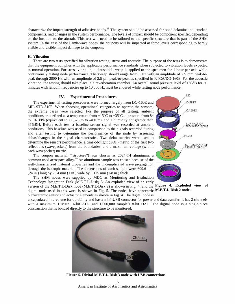
The SHM nodes were supplied by MDC as Monitoring and Evaluation Technology Integration Disk (M.E.T.I.-Disk) 3. An exploded view of an early version of the M.E.T.I.-Disk node (M.E.T.I.-Disk 2) is shown in Fig. 4, and the digital node used in this work is shown in Fig. 5. The nodes have concentric piezoceramic sensor and actuator elements as shown in Fig. 4. The digital node is encapsulated in urethane for durability and has a mini-USB connector for power and data transfer. It has 2 channels with a maximum 1 MHz 16-bit ADC and 1,000,000 sample/s 8-bit DAC. The digital node is a single-piece construction that is bonded directly to the structure to be monitored.
Figure 5. Digital M.E.T.I.-Disk 3 node with USB connections.
Figure 4. Exploded view of M.E.T.I.-Disk 2 node.

American Institute of Aeronautics and Astronautics
7
The nodes were bonded to the aluminum samples with AE-10 epoxy, a strain-gage adhesive. The node and sensor width are both 25.4 mm (1 in.). The adhesive is a two part mixture that has a working time of 15 minutes and a cure time at room temperature of 24-48 hours. The surface of the aluminum sample was prepared for node placement by sanding the area with 600-grit sandpaper and then cleaning the surface with isopropyl alcohol. The adhesive was mixed and applied to the bottom of the sensor and to the mounting surface of the aluminum, taking care to avoid bubbles. The sensor was then placed on the aluminum sample and worked around to force any air bubbles out. The node was centered (side-to-side) on the aluminum and the vertical alignment was verified. 5.44 kg (12 lbs.) of dead weight was rested upon the top of the node, with the aluminum sample on a level bench. Excess adhesive was immediately removed, and then the adhesive was allowed to cure for 48+ hours.
The nodes were bonded asymmetrically with respect to the specimen length to separate reflected wavepackets. This allowed the reflections to be pinpointed during signal processing. Boundary clamps were placed with their near edge 127 mm (5 in.) and 203.2 mm (8 in.) from center of the sensor as shown in Fig. 7. Each clamp was made of 6.35 mm (1/4 in.) thick steel. An ultrasonic shear couplant was placed between the aluminum coupon and boundary clamps to effectively produce an ‘edge’ boundary to the Lamb wave. The boundary clamp bolts were tightened to 0.11 N-m (100 lbs-in) to produce a pressure of 27.6 MPa (4000 psi) between the clamps and coupon. The completely assembled “SHM system” coupon that has been designed for use in all the tests described in section III is shown in Fig. 7, apart from the data-power mini-USB cable.
The experimental modulus and Poisson’s ratio of the aluminum structure were determined from three tensile tests. Two strain gages were attached to blank (no nodes) coupons and the samples were loaded. The resulting modulus, Poisson’s ratio, and yield stress were compared to those listed in MIL-HDBK-5J, and were found equivelant.20
A laptop PC was used to run the M.E.T.I.-System software that was developed by MDC. The software is a LabVIEW based program that allows control of the SHM system (adjusting parameters, discussed below). Connecting the sensor node to the PC via a USB cable and running the software allows communication between the node and program. The LabVIEW program sends the actuating signal and acquires the raw sensor data (voltage vs. time), writing both to a comma-delimited file. This file is imported to MATLAB where post-processing of the data can occur.
The excitation pulse sent to the actuator is a five-sine wave signal in a Hanning window. This excitation pulse has a driving frequency of 65 kHz and an amplitude of 5.8 volts peak-to-peak. The sensor acquires data at a sampling rate of 1000 kHz for 1 ms (1000 data points) per data set. Ten consecutive sets, spaced 200 ms apart, were recorded for each sensor assessment point. Data sets were acquired at the start of each test (the baseline signal), throughout the defined test (operational signal), and after the test was complete and ambient conditions were reestablished (post-test signal). The experimental graphs presented in the next section are averaged over the ten sets and then zeroed to their mean. The sensor signals are also inverted to make the comparison between the excitation pulse and the first measured sensor signal clear.
The static-strain test was conducted on a 100k lbf MTS tensile-compression machine with an Instron controller. The specimen was loaded in the machine and gripped past the boundary clamps. An axial displacement was then applied and the resulting tensile load was recorded. The displacement was held constant while the SHM system underwent functional tests. The displacement was increased until a stress near yield was produced. The displacement was then stepped back down until the specimen was unloaded, with functional test being preformed at each step. The high-temperature test was conducted in a small oven. The specimen was installed vertically with the lower boundary clamp resting on a fixture. The temperature was controlled by a proportional-integral-derivative (PID) controller that had the ability to ramp. The ramp was set to raise the temperature at 1.1˚C. Once the oscillation in temperature settled, the sensor was held at the elevated temperature for two hours. After the hold, the oven heaters were turned off, and the temperature was allowed to return to ambient overnight before the post-test was conducted.
One topic that must be addressed when tailoring the existing standards is defining what ‘device operating’ means to SHM systems. General avionic equipment is usually operating when power is applied (e.g., cockpit gages). SHM
Figure 7. Test coupon with node and boundary clamps.

American Institute of Aeronautics and Astronautics
8
systems do not have a clear operating condition. The SHM specific standards will need to define operating as the system powered, or the system operating (here, operating is sending and receiving Lamb-waves to the structure). For the tests conducted in this research, the ‘operating’ condition was chosen to be the SHM system powered and excitation pulses being constantly sent to the actuator. However, no data is recorded during ‘operation’.
V. Results An example pulse and received sensor signal is shown in Fig. 8. The two signals are the excitation pulse sent to
the actuator and the baseline sensed signal for the static-strain test and highlights the initial pulse received by the sensor (labeled 1), the antisymmetric (A0) mode reflection from the near boundary clamp (2), and the reflection from the far boundary clamp (3). The signals have been averaged over the 10 excitations, as described in the previous section. The excitation pulse signals for all tests (e.g., baseline and post-test) have been overlapped. The wavepackets in (2) and (3) were used for analyzing the delta metrics of the post-test signal deviations from the baseline. Theses two wavepackets are used with the delta metrics to determine the TOF difference and the peak voltage change between the baseline signal and the post-test signal for the static-strain and high-temperature experimental results.
The experimental TOF was visually determined at the midpoint of the reflected wavepackets (2 and 3). The TOF
was then adjusted so that the midpoint of the excitation pulse wavepacket occurs at time zero. The maximum voltage was determined from the absolute value of the signal data within the reflected wavepackets.
Experimental signals from the static-strain test are shown in Fig. 10. In the top graph, the five sine wave excitation pulse sent to the actuator is shown. The second graph is taken as the baseline response of the sensor, measured before any loading. This graph has been inverted to clearly show the initial pulse. The third graph shows the received signal when a strain of 200 microstrain is applied. It is clearly seen that there is a drop in received voltage, but the TOF has not shifted. The forth graph shows the response after the static test has been completed. Table 3 shows the experimental results from the static-strain test that are used to derive the delta metrics. The change in maximum voltage is -46% (averaged between wavepackets) and the change in the TOF metric is only 0.5%. The sensor node visually survived this test and showed no signs of failure. The source of the voltage degradation after the static-strain test is the subject of current work.
Table 2. Static-strain wavepacket characteristics.
TOF Peak Voltage 1st wavepacket 2nd wavepacket 1st wavepacket 2nd wavepacket Baseline 228 μs 311 μs 6.635 mV 6.403 mV Post-test 229 μs 313 μs 3.513 mV 3.541 mV
Figure 8. a) Excitation pulse. b) Baseline signal from static strain test, showing boundary reflections. 1- Initial pulse received by sensor, 2- reflection from near boundary clamp, 3- reflection from far boundary clamp.

American Institute of Aeronautics and Astronautics
9
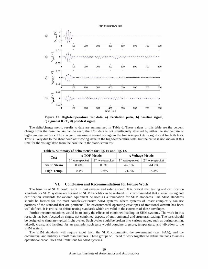
The high-temperature test was also completed. The recorded data from the high-temperature test is shown in Fig.
12. As in the previous case, Fig. 12a-b shows the pulse and baseline signal. The received signal at the end of the 85˚C high-temperature hold is shown in Fig. 12c, and Fig. 9d is the post-test signal. Table 4 lists the experimental results used to calculate the delta metrics. The TOF metric shows an average change of -0.5% between the baseline signal and the post-test signal. The voltage metric has an average change of -14.7% in the post-test signal. All three M.E.T.I.-Disk 3 nodes tested survived the high-temperature tests. There were no visual physical changes to the node or the adhesive. It was noted during the tests that the shear couplant became viscous at the elevated temperatures and flowed from the boundary clamps. This could account for the change in the voltage metric.
Figure 10. Static-strain test data. a) Excitation pulse, b) baseline signal, c) signal at 2700 μstrain, d) post-test signal.
Table 4. High-temperature wavepacket characteristics. TOF Peak Voltage 1st wavepacket 2nd wavepacket 1st wavepacket 2nd wavepacket
Baseline 221 μs 308 μs 4.620 mV 3.495 mV Post-test 220 μs 306 μs 3.619 mV 4.027 mV
American Institute of Aeronautics and Astronautics
10
The delta/change metric results to date are summarized in Table 6. These values in this table are the percent change from the baseline. As can be seen, the TOF data is not significantly affected by either the static-strain or high-temperature tests. The change in maximum sensed voltage in the two wavepackets is significant for both tests. This is likely due to the shear couplant flowing issue in the high-temperature tests, but the cause is not known at this time for the voltage drop from the baseline in the static-strain test.
VI. Conclusion and Recommendations for Future Work The benefits of SHM could result in cost savings and safer aircraft. It is critical that testing and certification
standards for SHM systems are formed so SHM benefits can be realized. It is recommended that current testing and certification standards for avionic equipment be used as a foundation for SHM standards. The SHM standards should be formed for the most complex/extensive SHM systems, where systems of lesser complexity can use portions of the standard that are pertinent. The environmental operating envelopes of traditional aircraft has been well defined. It is critical to define testing standards which are valid to the extremes of these envelopes.
Further recommendations would be to study the effects of combined loading on SHM systems. The work in this research has been focused on single, not combined, aspects of environmental and structural loading. The tests should be designed to simulate typical flight cycles. Such cycles could be broken into various stages, such as during taxiing, takeoff, cruise, and landing. As an example, such tests would combine pressure, temperature, and vibration to the SHM system.
The SHM standards will require input from the SHM community, the government (e.g., FAA), and the commercial and military aircraft manufactures. These groups will need to work together to define methods to assess operational capabilities and limitations for SHM systems.
Figure 12. High-temperature test data. a) Excitation pulse, b) baseline signal,c) signal at 85˚C, d) post-test signal.
Table 6. Summary of delta metrics for Fig. 10 and Fig. 12. Δ TOF Metric Δ Voltage Metric Test
1st wavepacket 2nd wavepacket 1st wavepacket 2nd wavepacket Static Strain 0.4% 0.6% -47.1% -44.7%
High Temp. -0.4% -0.6% -21.7% 15.2%

American Institute of Aeronautics and Astronautics
11
Appendix A Tables A-C summarize the testing categories defined in DO-160E, MIL-STD-810F, and MIL-STD-461E. The
highlighted tests are the down-selected categories used to define the test matrix used in this research, as described in the Current Test Standards section.
Table B. Testing standards defined by MIL-STD-810F.12
500 Low Pressure (Altitude) 501 High Temperature 502 Low Temperature 503 Temperature Shock 504 Contamination by Fluids 505 Solar Radiation (Sunshine) 506 Rain 507 Humidity 508 Fungus 509 Salt Fog 510 Sand and Dust 511 Explosive Atmosphere 512 Immersion 513 Acceleration 514 Vibration 515 Acoustic Noise 516 Shock 517 Pyroshock 518 Acidic Atmosphere 519 Gunfire Vibration 520 Temperature, Humidity, Vibration, and
Altitude 521 Icing/Freezing Rain 522 Ballistic Shock 523 Vibro-Acoustic/Temperature
Table A. Testing standards defined by RTCA/DO-160E.11
4.0 Temperature and Altitude 5.0 Temperature Variation 6.0 Humidity 7.0 Shock 8.0 Vibration 9.0 Explosion Proofness 10.0 Waterproofness 11.0 Fluids Susceptibility 12.0 Sand and Dust 13.0 Fungus Resistance 14.0 Salt Spray 15.0 Magnetic Effect 16.0 Power Input 17.0 Voltage Spike Conducted
18.0 Audio frequency Conducted Susceptibility
19.0 Induced Signal Susceptibility 20.0 RF Susceptibility 21.0 Emission of RF Energy
22.0 Lightning Induced Transient Susceptibility
23.0 Lightning Direct Effects 24.0 Icing 25.0 Electro-Static Discharge 26.0 Fire, Flammability 27.0 Smoke Density, Toxicity
Table C. Testing standards defined by MIL-STD-461E.13
CE101 Conducted Emissions, Power Leads 30 Hz to 10 kHz CE102 Conducted Emissions, Power Leads 10 kHz to 10 MHz CE106 Conducted Emissions, Antenna Terminal 10 kHz to 40 GHz CS101 Conducted Susceptibility, Power Leads 30 Hz to 150 kHz
CS103 Conducted Susceptibility, Antenna Port, Intermodulation 15 kHz to 10 GHz
CS104 Conducted Susceptibility, Antenna Port, Rejection of Undesired Signals 30 Hz to 20 GHz
CS105 Conducted Susceptibility, Antenna Port, Cross Modulation 30 Hz to 20 GHz
CS109 Conducted Susceptibility, Structure Current 60 Hz to 100 kHz CS114 Conducted Susceptibility, Bulk Cable Injection 10 kHz to 200 MHz CS115 Conducted Susceptibility, Bulk Cable Injection Impulse Excitation
CS116 Conducted Susceptibility, Damped Sinusoidal Transients, Cables and Power Leads 10 kHz to 100 MHz
RE101 Radiated Emissions, Magnetic Field 30 Hz to 100 kHz RE102 Radiated Emissions, Electric Field 10 kHz to 18 GHz
RE103 Radiated Emissions, Antenna Spurious and Harmonic Outputs 10 kHz to 40 GHz
RS101 Radiated Susceptibility, Magnetic Field 30 Hz to 100 kHz RS103 Radiated Susceptibility, Electric Field 2 MHz to 40 GHz
RS105 Radiated Susceptibility, Transient Electromagnetic Field

American Institute of Aeronautics and Astronautics
12
Acknowledgments The research presented in this paper was preformed at the Technology Laboratory for Advanced Materials and
Structures (TELAMS) at the Massachusetts Institute of Technology. The work was a collaboration with Metis Design Corporation (MDC) under a contract from the Air Force Office of Scientific Research (FA9550-05-C-0024).
References 1AC21-16E, US Department of Transportation, Federal Aviation Administration, Advisory Circular No: 21-16E, December
2005. 2Kessler, S.S., “Piezoelectric-Based In-Situ Damage Detection of Composite Materials for SHM Systems,” Ph.D. Thesis,
Dept. of Aeronautics and Astronautics, Massachusetts Institute of Technology, Cambridge, MA, January 2002. 3Kessler, S.S., Spearing, S.M., Atalla, M.J., Cesnik, C.E.S., and Soutis, C., “SHM in Composite Materials using Frequency
Response Methods,” Composites Part B, Vol. 33, January 2002, pp. 87-95. 4Kessler, S.S., Spearing, S.M., and Soutis, C., “SHM in Composite Materials using Lamb Wave Methods,” Smart Materials
and Structures, Vol. 11, April 2002, pp. 269-278. 5Kessler, S.S., Spearing, S.M., Shi, Y., and Dunn, C.T., “Packaging of SHM Components,” Proceedings of the SPIE’s 11th
International Symposium on Smart Structures and Materials, San Diego, CA, 14-18 March 2004, pp. 219-229. 6Kessler, S.S., and Shim, D.J., “Validation of a Lamb Wave-Based SHM for Aircrafts,” Proceedings of the SPIE’s 12th
International Symposium on Smart Structures and Materials, San Diego, CA, 7-10 March 2005, pp. 293-301. 7Bar-Cohen, Y., “Emerging NDE Technologies and Challenges at the Beginning of the 3rd Millennium,” Materials
Evaluation, Vol. 58, 2000. 8Chang, F-K, “Structural Health Monitoring: A Summary Report,” Proceedings of the 2nd International Workshop on
Structural Health Monitoring, Stanford, CA, September 8-10, 1999. 9Giurgiutiu, V., “Tuned Lamb-Wave Excitation and Detection with Piezoelectric Wafer Active Sensors for Structural Health
Monitoring,” Journal of Intelligent Material Systems and Structures, Vol. 16, 16 April 2005, pp. 291-306. 10Kessler, S.S., “Certifying a Structural Health Monitoring System: Characterizing Durability, Reliability and Longevity,”
Proceedings of the 1st International Forum on Integrated Systems Health Engineering and Management in Aerospace , Napa, CA, 7-10 November 2005.
11RTCA/DO-160E, “Environmental Conditions and Test Procedures for Airborne Equipment,” RTCA Paper No. 111-04/SC135-645, Washington, DC, December 2004.
12MIL-STD-810F, “Department of Defense Test Method Standard for Environmental Engineering Considerations,” January 2000 (original), November 2000, August 2002, and May 2003 (change notices 1-3).
13MIL-STD-461E, “Department of Defense Interface Standard Requirements for the Control of Electromagnetic Interference Characteristics of Subsystems and Equipment,” August 1999.
14MIL-HDBK-310, “Global Climatic Data for Developing Military Products,” June 1997. 15AC29-2C, Department of Transportation, Federal Aviation Administration 16Kessler, S.S., Amaratunga, K., and Wardle, B.L., “An Assessment of Durability Requirements for Aircraft Structural
Health Monitoring Sensors,” Proceedings of the 5th International Workshop on Structural Health Monitoring, Stanford, CA, September 12-14, 2005.
17ASTM E 466-96(2002)ε1, “Conducting Force Controlled Constant Amplitude Axial Fatigue Tests of Metallic Materials,” ASTM International.
18ASTM D 950-03, “Standard Test Method for Impact Strength of Adhesive Bonds,” ASTM International. 19SPD-10-036, “Alloy 2024 Sheet and Plate,” ALCOA, Inc. 20MIL-HDBK-5J, “Metallic Materials and Elements for Aerospace Vehicle Structures,” January 2003.