experimental and theoretical analysis of lamb wave
TRANSCRIPT
Experimental and Theoretical Analysis of Lamb WaveGeneration by Piezoceramic Actuators for StructuralHealth Monitoring
J. Pohl & C. Willberg & U. Gabbert & G. Mook
Received: 24 January 2011 /Accepted: 17 April 2011# Society for Experimental Mechanics 2011
Abstract Piezoceramic transducers, acting as actuators andsensors, are attractive for generation and reception of Lambwaves in Structural Health Monitoring (SHM) systems. Toget insight into the source-mechanisms of Lamb waves,the vibrations of piezoceramic actuators are analyzed forthe free and bonded state of the piezoceramic byanalytical and finite element (FEM) calculations. Modeshapes and spectra of piezoceramic actuators and Lambwave fields are experimentally recorded by scanninglaser vibrometry. The analytical solutions for bendingmodes are shown to be valid for large diameter-to-thickness-relations of a free piezoactuator (D/H>10)only. For thicker piezoceramics, a FEM-solution givesbetter results. Calculated frequencies for radial modes ofvibration are confirmed by 3-D-laser-vibrometry andmeasurements of electrical impedance. The bonded caseof a piezoactuator exhibits a broad resonance peakresulting from the strong coupling between radial andbending modes. The assumption that optimal excitationof Lamb modes occurs for a matching of the wavelengthsto the diameter of the piezoceramic holds only for thinceramics. Otherwise the distinct modes of out-of-plane
and in-plane vibrations control the excitation of theLamb modes more than the wavelength matching.
Keywords Lamb waves . Structural health monitoring .
Piezoceramic actuator
Introduction
Structural Health Monitoring (SHM) is a new, rapidlydeveloping technology for the monitoring of engineeringstructures [1–6]. The main features are permanent andautomatic assessment of the structural integrity by built-indevices such that non-destructive testing becomes anintegral part of the structure. Therefore, SHM aims atdamage detection and loads monitoring by intrinsic meansof the structure. Consequently, a SHM-system requiresbuilt-in sensors to provide this new functionality, and ifnecessary, for the generation of diagnostic signals, actuatorsas well. The tasks can be defined similar to those ofconventional non-destructive testing: damage detection,localisation and further characterisation. The final goal isan estimation of the remaining life time of the structure.
The new monitoring approach of SHM replaces conven-tional maintenance concepts with fixed inspection intervalsby more effective condition-based maintenance conceptswhere actions are taken only if required [6].
Among different approaches, the use of ultrasonic Lambwaves is an attractive method for structural health monitoring.Lamb waves are able to propagate over large distances, thuswide areas of a structure can be monitored. Because Lambwaves sensitively interact with defects, they offer a chance fordefect detection and further characterization.
SHM-systems using Lamb waves require effectivemeans for generating and receiving Lamb wave modes.The use of embedded or surface-attached piezoceramic
J. Pohl (*)Department of Electrical, Mechanical and IndustrialEngineering (EMW), Anhalt University of Applied Sciences,Bernburger Str. 55,06366 Köthen, Germanye-mail: [email protected]
C. Willberg :U. GabbertInstitute of Mechanics (IFME), Otto-von-Guericke-University,PF 4120, 39016 Magdeburg, Germany
G. MookInstitute of Materials and Joining Technology (IWF),Otto-von-Guericke-University,PF 4120, 39016 Magdeburg, Germany
Experimental MechanicsDOI 10.1007/s11340-011-9503-2
elements as actuators and sensors for generation andreception of Lamb waves is an attractive way for designingsmart SHM-structures [1, 2, 4-6].
The paper contributes to a better understanding of thegeneration process of Lamb waves which are excited bypiezoelectric patch actuators bonded to the surface of alightweight structure. For creating effective SHM-systems it isnecessary to understand in detail the generation process ofLamb waves. The multimodal, frequency-dependent proper-ties of Lamb waves [7], the complexity of modal behaviourof piezoceramic elements and the influence of couplingconditions are investigated experimentally as well astheoretically. It is shown that the natural vibration behaviourof a piezoelectric patch coupled by a bonding layer to thestructure can be used for a more effective wave excitation. Itis also shown that the classical rule of thumb, which relatesthe optimal excitation frequency to the geometry of apiezoelectric patch actuator, only holds for very thin patchesand fails for more realistic thicker patches.
The paper is organized as follows. At first the freevibration of circular piezoelectric patches are investigatedtheoretically as well as experimentally. Then the dynamicbehaviour of circular patches bonded to the structure isstudied and the relation between the geometry of the patchactuator and the applied frequency is investigated in detail.Here it is also shown that directional wave effects can occureven if all involved materials are isotropic. The paperfinishes with a brief conclusion.
Vibrations of Free Piezo-Actuators
We start with theoretical and experimental investigations ofvibrations of free circular piezoceramic plates. Out-of-planeand in-plane vibration modes of the piezoceramic plate willactivate the different Lamb modes [1, 2, 8–10]. Out-of-plane modes are represented by modes designated astransverse, bending or flexural modes and thickness modesof the plate, in-plane modes by radial and torsional ones.Due to coupling effects nearly all modes will show out-ofplane as well as in-plane components of particle displace-ment. Because thickness modes for the piezoceramic plateswith thicknesses less than 2 mm considered here occur atfrequencies higher than 1 MHz, these modes are not takeninto consideration. Torsional modes are excluded as wellbecause of their weak signal strength.
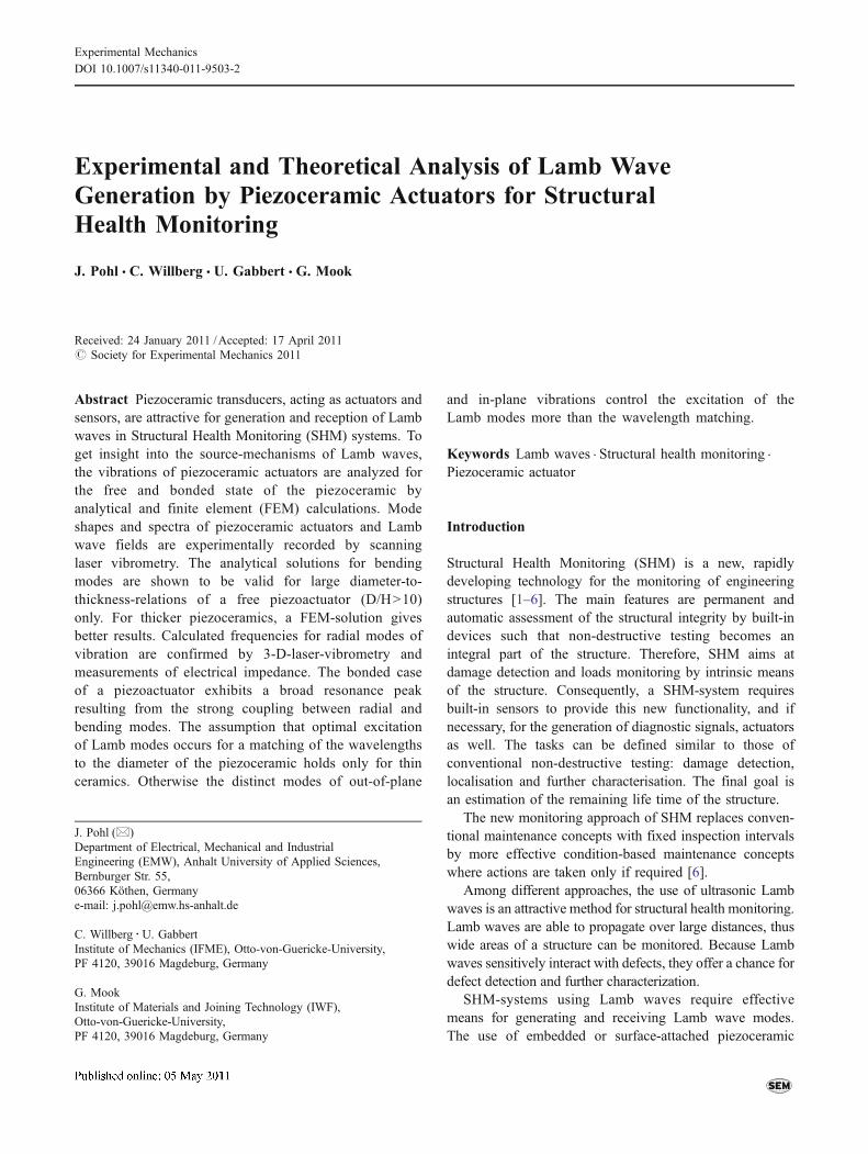
Free modes are generally a valuable starting point for thetreatment of the vibration modes of piezo-plates that arebonded to a structure. Figure 1 schematically shows thecoordinate system and the geometric parameters.
Investigations of different modes of vibration of freepiezoceramic discs comparing analytical and FEM solu-tions with experimental results were done by Huang et al.
[10]. Following this work, the analytical solution (platetheory) for the resonance frequencies of bending modes ofthe piezoceramic disc under a constant electrical field isgiven by equation (1). The 1–2 directions match with theisotropic plane in radial direction, shown in Fig. 1. Thedirection 3 is perpendicular to that plane and relates to thepolarization of the piezoceramic material.
fj;p ¼ffiffiffiffiffiffiffiffiffiffiffiffiffiffiffiffiffiffiffiffiffiffiffiffiffiffiffiffiffiffiffiffiffiffiffiffiffiffiffiffiffiffiffiffiffiffiffiffiffiffiffiffiffi
2� 1� n12ð Þk21224r SE11 1� n212
� �1� k212� �
sh
2p r2max
b2j;p with
k12 ¼ffiffiffiffiffiffiffiffiffiffiffiffiffiffiffiffiffiffiffiffiffiffiffiffiffiffiffiffiffiffiffi
2d231"33SE11 1� n12ð Þ
sð1Þ
Here SE11 is the compliance in the isotropic plane, ν12 thePoisson’s ratio, d31 the electromechanical coupling coeffi-cient, ε33 the permittivity and ρ the density. The values ofβj,p are the natural eigenvalues of the solution for a free-freecircular piezoceramic plate. The values j, p are defined asthe number of nodal circles and nodal diameters respec-tively. It was shown that the error between the experimentalresult, the analytical solution and the FEM solution for the
Fig. 1 Coordinate system of a circular plate with radius rmax, platethickness h and amplitude Wj,p
Table 1 Material properties of PIC-181
PIC-181 ceramics
SE1 [10−12m2/N] 11.75
SE33 14.11
SE55 35.33
SE12 −4.070SE13 −4.996SE44 35.33
SE66 31.64
d31 [10−10m/V] −1.08d33 2.53
d15 3.89
"T11="0 [−] 1224
"T33="0 1135
ρ [kg/m3] 7850
Exp Mech
transversal vibrations is small for a diameter D to thicknessh ratio of D/h>10 [10].
For our investigations no constant electrical field applies.Then equation (1) becomes the pure elastic description ofequation (2). This equation, given by Itao [11] and used byGiurgiutiu and Huang et al. [2, 10] shows the analyticalsolution for bending modes of a circular free-free platewithout including the piezoelectric behaviour. Theseassumptions are also used for our FEM simulation.
fj;p ¼ffiffiffiffiffiffiffiffiffiffiffiffiffiffiffiffiffiffiffiffiffiffiffiffiffiffiffiffiffiffiffiffiffi
1
12SE11r 1� n212� �
sh
2p r2max
l2j;p ð2Þ
The values of 1 j,p are the natural eigenvalues of thesolution for a free-free circular elastic plate. To comparethe measurements with the theoretical solutions of theeigenfrequencies, the mode shapes have to be considered.Equation (3) gives the displacement Wj,p in x3-directionshown in Fig. 1. With the Bessel functions J and I, theamplitude Aj,p, and the mode shape parameter Cj,p , thecorrelated eigenform to the frequency fj,p from equation(2) can be calculated [12]. The material properties of atypical piezoceramic material under investigation (PI-181
from PI Ceramics), given by the manufacturer, areillustrated in Table 1.
Wj;pðr;6Þ ¼ Aj;p Jplj;prrmax
� �þ Cj;pIP
lj;prrmax
� �� �cos p6 ð3Þ
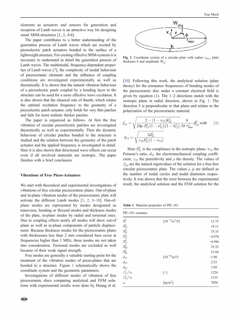
For experimental validation of theoretical results themode shapes and spectra of free and bonded piezoceramicactuators and the resulting Lamb wave fields were recordedwith 1D- and 3D-scanning laser vibrometers (Polytec PSV300 and Polytec PSV 400). Scanning laser vibrometryrepresents an interferometric method with high sensitivityfor non-contact detection of small displacements of wavefields or vibrations [13–16].
The principal setup of the laservibrometric measure-ments is displayed in Fig. 2. The specimen—in the case ofvibration measurements represented by the piezoceramictransducers under investigation—was scanned point-by-point to resolve the mode shapes. The electrical excitationof the piezoceramic was performed with chirp signals,covering successively a frequency region of 0.5 to 300 kHz(in some cases up to 500 kHz).
Different circular discs from PI Ceramics and Marco, madefrom hard and soft lead zirconate titanate materials (PIC 151,PIC 181, FPM 100 and FPM 202), were used as piezoceramicactuators. The diameters ranged from 10 to 40 mm, thethicknesses from 0.5 to 2mm. All discs had wrapped electrodesproviding electrical contacts at the free side of the transducer.To reveal the in-plane modes of vibrationmore unambiguously,investigations with a 3D-laser vibrometer (PSV 400 3D) weremade for some piezo-actuators in addition to two-dimensionalscans of the out-of-plane displacements with the PSV-300,allowing the recording of all three components of displacement.
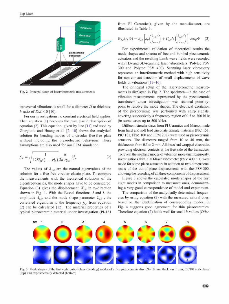
Figure 3 shows the calculated mode shapes of the firsteight modes in comparison to measured ones, demonstrat-ing a very good correspondence of model and experiment.
The comparison of the analytically determined frequen-cies by using equation (2) with the measured natural ones,based on the identification of corresponding modes, inFig. 4 suggests good agreement for thin piezoceramics.Therefore equation (2) holds well for small h-values (D/h>
Fig. 3 Mode shapes of the first eight out-of-plane (bending) modes of a free piezoceramic disc (D=10 mm, thickness 1 mm, PIC181) calculated(top) and experimentally detected (bottom)
Fig. 2 Principal setup of laservibrometric measurements
Exp Mech

10). For thicker piezoceramics, a FEM-solution calculatedwith the FEM-program ABAQUS gives better results andfits very well with the experimental results.
To calculate the free radial (in-plane) modes analytically,equation (4) is used [2, 10]. The values zn are theeigenvalues of the analytical in-plane solution. The solutionis independent from the electromechanical coupling terms[10]. Here zn are the non trivial solutions of the generalequation for axial vibration of the circular plate [2].
fn ¼ffiffiffiffiffiffiffiffiffiffiffiffiffiffiffiffiffiffiffiffiffiffiffiffiffiffiffiffi
1
SE11r 1� n212� �
szn
2p rmaxð4Þ
3D-laser scanning measurements show that these in-planemodes also remarkably produce secondary out-of-plane
components of displacement. It was observed that even in1D-laser vibrometric generated out-of-plane spectra radialmode peaks became visible. In those cases it was not possibleto correlate a fundamental bending mode shape shown inFig. 3 (and higher ones too) with the measured peaks. FEM-simulations show that many bending modes coexist aroundthe higher resonance frequencies of the first radial mode.This was validated by the experimental results. In Fig. 5, forexample, the position of the first radial mode marked by anarrow is surrounded by several bending modes in thisfrequency region. A splitting of the mode types by this 1D(out-of-plane) measurements is not possible. As the right partof Fig. 5 shows, 3D-measurements allow an unambiguousidentification of in-plane modes even in these complicatedsituations.
Following Huang et al. [10] only in-plane and thicknessmodes cause resonance peaks in the spectrum of electricalimpedance. To additionally validate the resonance values, theimpedance was measured with a network analyzer AdvantestR3751 A. Table 2 compares the calculated frequencies of thefirst radial mode with the 3D-measured ones and valuesobtained with impedance measurements. As equation (4)states, a change of the height of the piezoceramic disc has noinfluence on the resonance frequencies.
Vibrations of Bonded Piezo-Actuators
To investigate the case of bonded piezoceramic actuators,the situation was modelled with FEM. The adhesive layer
Fig. 5 Spectrum of free vibra-tions of a piezoceramic disc(D=10 mm, h=1 mm, PIC 151),measured with 1D-laservibrometer (left) and first radialmode shape, recorded with3D-vibrometer (right)
Diameter[mm]
Material Height[mm]
Calculatedfrequency[kHz]
Measured frequency(3-D vibrometer)[kHz]
Measured frequency(impedance)[kHz]
10 PIC 151 1 190.77 195 195
10 PIC 181 0.5 228.32 222 225
10 PIC 181 1 228.32 225 224
10 PIC 181 2 228.32 224 223
40 PIC 151 0.5 47.69 – 49
15 FPM 100 2 152.54 154 155
20 FPM 202 1 95.39 – 100
Table 2 Calculated andmeasured frequencies for thefirst radial mode
Fig. 4 Comparison of theoretical solutions (pure elastic) andexperimental results of the nth order frequencies f of free piezoceramicdiscs (D=10 mm, PIC181) with different thicknesses h
Exp Mech

was considered as an isotropic material with differentheights and Young’s moduli. By including the adhesivelayer, effects connected with its properties, e.g. the shearlag effect, are taken into account [17].
To initially consider isotropic media for Lamb waves,the piezo-actuators were bonded to a polystyrene (PS) platewith 4.75 mm thickness and to a plate of polymethylme-thacrylate (PMMA) with 3 mm thickness. To achieve areversible coupling to the structure, the bonding wasperformed by paraffin. The thickness of the bonding layerwas between 10 and 40 μm for all plates. Materialproperties of the bonding layer were taken from theliterature (E=1.02 GPa, ν=0.37, ρ=910 kg/m3) [18] andalso determined directly by measurements of ultrasonicwave velocities (E=1.2 GPa, ν=0.4).
Figure 6 displays the 15th calculated eigenmode of abonded piezoceramic plate, which is the second mode with asignificant contribution of in-plane displacements in relationto the out of plane displacements. So, this mode isdesignated second bending-radial eigenmode. Due to thecoupling of the piezoceramic actuator with the plate by anadhesive layer no pure radial modes occur as in a freecircular plate. The error of solutions of the radial eigen-frequencies is around 4%. The bending axis shifts indirection of the plate and a bending moment will be induced.If the frequency of a bending mode is close to the frequency
of a radial mode, both modes will be activated. Thesimulations of the coupled piezoceramic (D=10 mm, h=1 mm, PI 181, hbond=40 μm) have shown the second radialmode at 254 kHz. Five axially symmetric bending modes arein a frequency range of plus minus ten percent. Thisexpresses the strong coupling between radial and bendingmodes in such cases. The 3D-laser vibrometer measurementsconfirm this but don’t reveal the radial modes clearly. AsFig. 7 (left) shows, the strong peak between 200 and300 kHz is caused by a mode which dominantly assumes abending eigenform in the mode shape image (right). Themeasurement of the in-plane displacement confirms thecoupling of the in-plane and out-of-plane vibration andshows the in-plane components of the displacements to behigher than in the free vibration state. For these increasedvalues two reasons are possible. The first is a shift of thebending axis from the middle of the disc towards the platedue to the bonding. As a result, the displacement at themeasured top plane of the disc must be higher.
The radial modes which exist in that range are thesecond reason for an elevation of the in-plane components.Figure 7 (left) shows a wide peak between 205 and270 kHz. The bending mode, shown in Fig. 7 (right) isthe same for the whole frequency range of the peak. Thearea of the shadowing electrical wires is removed to avoiddisturbances of the spectrum.
The mode properties clearly show the mixture be-tween the bending and the radial modes. The in-planespectrum of the 3D-measurements displays the samebehaviour as shown in Fig. 7. The associated shapes ofthe radial modes are not unambiguously detectable in thearea plot of the in-plane displacements but the data ofmeasurements of electrical impedance resonances inTable 3 reveal radial modes at the edges of the peakregion, e.g. the second radial mode at 262 kHz. A shift tolower frequencies occurs for increasing thickness of thepiezoceramic. In summary, vibrometry as well as imped-ance measurements indicate the coupling effects ofbending and radial modes producing a wide resonanceregion with strong amplitudes.
Fig. 6 Second calculated radial mode of a coupled piezoceramic disc(D=10 mm, h=0.5 mm, PIC 181) for a PMMA plate
Fig. 7 Out-of-plane spectrumof a piezoceramic disc(D=10 mm, h=1 mm PI 181)(left) bonded to a PMMA plate,and mode shape (right),measured with 3D laservibrometer
Exp Mech
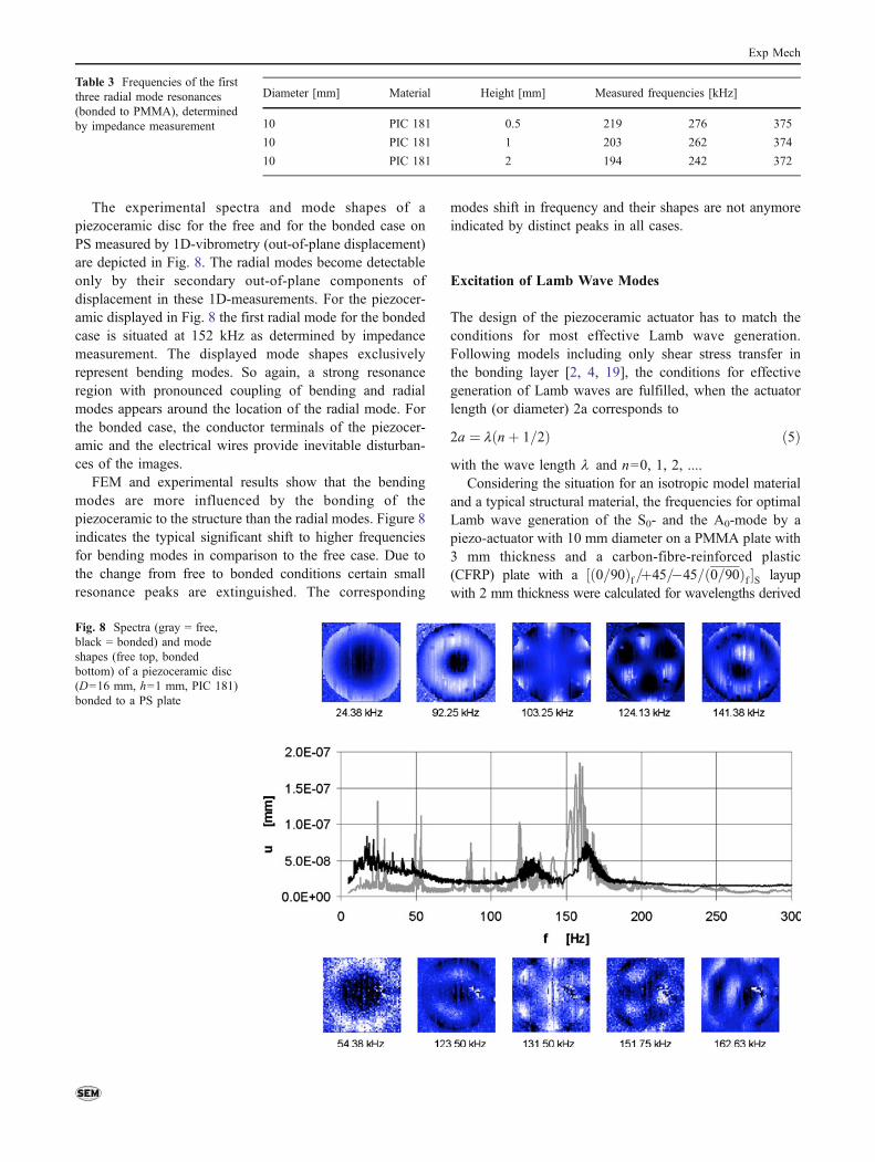
The experimental spectra and mode shapes of apiezoceramic disc for the free and for the bonded case onPS measured by 1D-vibrometry (out-of-plane displacement)are depicted in Fig. 8. The radial modes become detectableonly by their secondary out-of-plane components ofdisplacement in these 1D-measurements. For the piezocer-amic displayed in Fig. 8 the first radial mode for the bondedcase is situated at 152 kHz as determined by impedancemeasurement. The displayed mode shapes exclusivelyrepresent bending modes. So again, a strong resonanceregion with pronounced coupling of bending and radialmodes appears around the location of the radial mode. Forthe bonded case, the conductor terminals of the piezocer-amic and the electrical wires provide inevitable disturban-ces of the images.
FEM and experimental results show that the bendingmodes are more influenced by the bonding of thepiezoceramic to the structure than the radial modes. Figure 8indicates the typical significant shift to higher frequenciesfor bending modes in comparison to the free case. Due tothe change from free to bonded conditions certain smallresonance peaks are extinguished. The corresponding
modes shift in frequency and their shapes are not anymoreindicated by distinct peaks in all cases.
Excitation of Lamb Wave Modes
The design of the piezoceramic actuator has to match theconditions for most effective Lamb wave generation.Following models including only shear stress transfer inthe bonding layer [2, 4, 19], the conditions for effectivegeneration of Lamb waves are fulfilled, when the actuatorlength (or diameter) 2a corresponds to
2a ¼ l nþ 1=2ð Þ ð5Þwith the wave length 1 and n=0, 1, 2, ....
Considering the situation for an isotropic model materialand a typical structural material, the frequencies for optimalLamb wave generation of the S0- and the A0-mode by apiezo-actuator with 10 mm diameter on a PMMA plate with3 mm thickness and a carbon-fibre-reinforced plastic(CFRP) plate with a ½ð0=90Þf=þ45=�45=ð0=90Þf �S layupwith 2 mm thickness were calculated for wavelengths derived
Diameter [mm] Material Height [mm] Measured frequencies [kHz]
10 PIC 181 0.5 219 276 375
10 PIC 181 1 203 262 374
10 PIC 181 2 194 242 372
Table 3 Frequencies of the firstthree radial mode resonances(bonded to PMMA), determinedby impedance measurement
Fig. 8 Spectra (gray = free,black = bonded) and modeshapes (free top, bondedbottom) of a piezoceramic disc(D=16 mm, h=1 mm, PIC 181)bonded to a PS plate
Exp Mech

from equation (5) and are given in Table 4 for frequencies upto 500 kHz. Measured dispersion curves for Lamb waves [20]were used for the determination of the frequencies for thegiven wavelength values.
Figures 9, 10, 11 and 12 display the measured area-averaged spectra of the A0- and S0-mode in the PMMA andCFRP plates for a propagation distance of 200 mm. TheLamb waves were generated by actuators with the samediameter of 10 mm and different heights of 0.5 to 2 mm. Thepositions of frequencies of optimal excitation calculated withequation (5) are marked by gray lines and arrows.
The frequencies with pronounced amplitude do notcorrelate in all cases with the calculated ones. This holdstrue for the other piezoceramics (not displayed here). In thelower frequency domain up to about 100 kHz A0 isproduced with high amplitudes by thin piezoceramics. Thisis explained by the bending modes which are dominant inproducing the A0 mode with high amplitudes. Thesebending modes are seen with relatively high amplitudes inthe spectra of the bonded piezoceramic actuators in Figs. 13and 14. Due to the governing role of bending stiffness afrequency shift toward higher values occurs and theeffectivity of the A0-generation for lower frequenciesdecreases with increasing thickness of the actuator.
The low frequency maximum of A0 excitation agreesfairly well with the predicted value for n=0 (Table 4) forthin piezoceramics. For thicker piezoceramic actuatorsequation (5) does not hold true.
The other calculated maxima of A0 generation in Table 3are not apparent or only correspond to peaks of lowamplitude.
As Figs. 13 and 14 show, the dynamics of the actuatorcause strong amplitudes between 200 and 300 kHz which donot match the values of equation (5) but are reflected by thespectra of A0 in Figs. 9 and 11. In sum, the results display amore effective generation of A0 by only the bending modesat lower frequencies and of coupled bending and radialmodes at higher ones corresponding to the highest resonancepeaks in the spectra of the piezoceramics.
As Figs. 13 and 14 display, a wide peak with strongamplitudes occurs between 200 and 300 kHz. At these
Fig. 10 Spectra of the S0-mode for piezoceramic discs with 10 mmdiameter, (a) h=0.5 mm, (b) h=1.0 mm, (c) h=2.0 mm bonded to aPMMA-plate
Fig. 11 Spectra of the A0-mode for piezoceramic discs with 10 mmdiameter, (a) h=0.5 mm, (b) h=1.0 mm, (c) h=2.0 mm bonded to aCFRP-plate
Fig. 12 Spectra of the S0-mode for piezoceramic discs with 10 mmdiameter, (a) h=0.5 mm, (b) h=1.0 mm, (c) h=2.0 mm bonded to aCFRP-plate
Table 4 Optimal frequencies for Lamb mode generation in a PMMAand a CFRP plate up to 500 khz
n 1 [m] PMMA CFRP
f of A0
[Hz]f of S0[Hz]
f of A0
[Hz]f of S0[Hz]
0 0.0200 26000 117000 40700 276000
1 0.0067 149000 308200 186000 –
2 0.0040 284700 394500 335000 –
3 0.0029 411600 480700 480000 –
Fig. 9 Spectra of the A0-mode for piezoceramic discs with 10 mmdiameter, (a) h=0.5 mm, (b) h=1.0 mm, (c) h=2.0 mm bonded to aPMMA-plate
Exp Mech
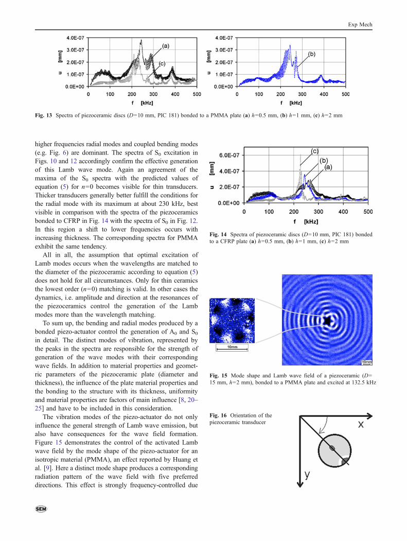
higher frequencies radial modes and coupled bending modes(e.g. Fig. 6) are dominant. The spectra of S0 excitation inFigs. 10 and 12 accordingly confirm the effective generationof this Lamb wave mode. Again an agreement of themaxima of the S0 spectra with the predicted values ofequation (5) for n=0 becomes visible for thin transducers.Thicker transducers generally better fulfill the conditions forthe radial mode with its maximum at about 230 kHz, bestvisible in comparison with the spectra of the piezoceramicsbonded to CFRP in Fig. 14 with the spectra of S0 in Fig. 12.In this region a shift to lower frequencies occurs withincreasing thickness. The corresponding spectra for PMMAexhibit the same tendency.
All in all, the assumption that optimal excitation ofLamb modes occurs when the wavelengths are matched tothe diameter of the piezoceramic according to equation (5)does not hold for all circumstances. Only for thin ceramicsthe lowest order (n=0) matching is valid. In other cases thedynamics, i.e. amplitude and direction at the resonances ofthe piezoceramics control the generation of the Lambmodes more than the wavelength matching.
To sum up, the bending and radial modes produced by abonded piezo-actuator control the generation of A0 and S0in detail. The distinct modes of vibration, represented bythe peaks in the spectra are responsible for the strength ofgeneration of the wave modes with their correspondingwave fields. In addition to material properties and geomet-ric parameters of the piezoceramic plate (diameter andthickness), the influence of the plate material properties andthe bonding to the structure with its thickness, uniformityand material properties are factors of main influence [8, 20–25] and have to be included in this consideration.
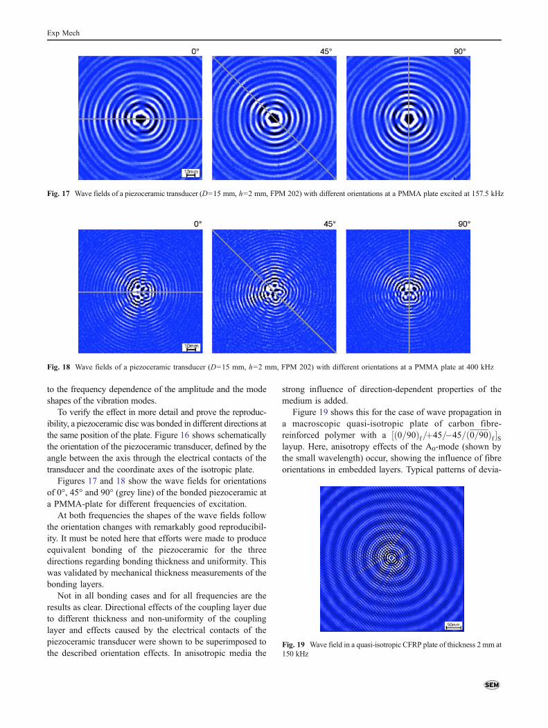
The vibration modes of the piezo-actuator do not onlyinfluence the general strength of Lamb wave emission, butalso have consequences for the wave field formation.Figure 15 demonstrates the control of the activated Lambwave field by the mode shape of the piezo-actuator for anisotropic material (PMMA), an effect reported by Huang etal. [9]. Here a distinct mode shape produces a correspondingradiation pattern of the wave field with five preferreddirections. This effect is strongly frequency-controlled due
Fig. 14 Spectra of piezoceramic discs (D=10 mm, PIC 181) bondedto a CFRP plate (a) h=0.5 mm, (b) h=1 mm, (c) h=2 mm
Fig. 15 Mode shape and Lamb wave field of a piezoceramic (D=15 mm, h=2 mm), bonded to a PMMA plate and excited at 132.5 kHz
Fig. 16 Orientation of thepiezoceramic transducer
Fig. 13 Spectra of piezoceramic discs (D=10 mm, PIC 181) bonded to a PMMA plate (a) h=0.5 mm, (b) h=1 mm, (c) h=2 mm
Exp Mech
to the frequency dependence of the amplitude and the modeshapes of the vibration modes.
To verify the effect in more detail and prove the reproduc-ibility, a piezoceramic disc was bonded in different directions atthe same position of the plate. Figure 16 shows schematicallythe orientation of the piezoceramic transducer, defined by theangle between the axis through the electrical contacts of thetransducer and the coordinate axes of the isotropic plate.
Figures 17 and 18 show the wave fields for orientationsof 0°, 45° and 90° (grey line) of the bonded piezoceramic ata PMMA-plate for different frequencies of excitation.
At both frequencies the shapes of the wave fields followthe orientation changes with remarkably good reproducibil-ity. It must be noted here that efforts were made to produceequivalent bonding of the piezoceramic for the threedirections regarding bonding thickness and uniformity. Thiswas validated by mechanical thickness measurements of thebonding layers.
Not in all bonding cases and for all frequencies are theresults as clear. Directional effects of the coupling layer dueto different thickness and non-uniformity of the couplinglayer and effects caused by the electrical contacts of thepiezoceramic transducer were shown to be superimposed tothe described orientation effects. In anisotropic media the
strong influence of direction-dependent properties of themedium is added.
Figure 19 shows this for the case of wave propagation ina macroscopic quasi-isotropic plate of carbon fibre-reinforced polymer with a ½ð0=90Þf=þ45=�45=ð0=90Þf �Slayup. Here, anisotropy effects of the A0-mode (shown bythe small wavelength) occur, showing the influence of fibreorientations in embedded layers. Typical patterns of devia-
Fig. 18 Wave fields of a piezoceramic transducer (D=15 mm, h=2 mm, FPM 202) with different orientations at a PMMA plate at 400 kHz
Fig. 19 Wave field in a quasi-isotropic CFRP plate of thickness 2 mm at150 kHz
Fig. 17 Wave fields of a piezoceramic transducer (D=15 mm, h=2 mm, FPM 202) with different orientations at a PMMA plate excited at 157.5 kHz
Exp Mech
tions of phase directions and bending of energy transportdirections are indicators for this whereas the basic symmet-ric mode S0 shows no influence of fibre directions ofdifferent layers.
In summary, the influence of coupling layers as well as theeffects of anisotropy cannot be ignored and have to be includedin the consideration of the Lamb wave generation process.
Conclusions
The characteristics of the vibrations of the piezo-actuatorcontrol the generated lamb wave field. The combination oftheoretical considerations and laser-vibrometric observationsof the piezo-actuator vibration and Lamb wave propagationhelps to explain the complex situation. Impedance measure-ments are helpful to further describe radial modes of vibration.Starting from free vibrations of the piezoceramic actuator thebonded case exhibits a broad resonance peak with largeamplitudes which results from the strong coupling betweenthe radial and the bending modes. Bending modes aregenerally shifted to higher frequencies.
Depending on the geometry of the actuator, thebending and radial modes of vibration describe thefrequency dependent generation of Lamb waves. Theassumption that optimal excitation of Lamb modesoccurs for a matching of the wavelengths to the diameterof the piezoceramic does not hold for all circumstances.Only for thin ceramics the lowest order matching isconfirmed. Otherwise the distinct modes with theiramplitude and direction of vibration control the excita-tion of the Lamb modes more than the wavelengthmatching. In order to apply this knowledge for designingan efficient actuator configuration a detailed finiteelement simulation is required. A simpler extended ruleof thumb could not be developed until know.
A detailed investigation of the different modes ofvibration helps to further reveal the radiation patterns ofLamb wave transducers. Influences of the coupling layerand anisotropy effects must be included in furtherinvestigations.
Acknowledgments The authors like to thank the German ResearchFoundation (DFG) and all partners for their support (GA 480/13-1,MO 553/9-1).
References
1. Boller C, Chang F-K, Fujino Y (2009) Encyclopedia of structuralhealth monitoring. Wiley & Sons, Chichester
2. Giurgiutiu V (2008) Structural health monitoring with piezoelec-tric wafer active sensors. Elsevier Academic Press, New York.ISBN 9780120887606
3. Park G, Sohn H, Farrar CR, Inman DJ (2003) Overview ofpiezoelectric impedance based health monitoring and pathforward. Shock Vib Dig 35(6):451–463
4. Su Z, Ye L, Lu Y (2006) Guided Lamb waves for identification ofdamage in composite structures: a review. J Sound Vib 295:753–780
5. Raghavan A, Cesnik CES (2007) Review of guided-wavestructural health monitoring. Shock Vib Dig 39:91–114
6. Boller C, Staszewski W, Tomlinson G (2004) Health monitoringof aerospace structures. Wiley. ISBN 0-470-84340-3
7. Viktorov IA (1967) Rayleigh and Lamb waves. Plenum Press,New York
8. Ha S, Chang F-K (2010) Adhesive interface layer effects in PZT-induced Lamb wave propagation. Smart Mater Struct 19:025006
9. Huang H, Pamphile T, Derriso M (2008) The effect of actuatorbending on Lamb wave displacement fields generated by apiezoelectric patch. Smart Mater Struct 17:1–13
10. Huang C-H, Lin Y-C, Ma C-C (2004) Theoretical analysis andexperimental measurement for resonant vibration of piecoceramiccircular plates. IEEE Trans Ultrason Ferroelectrics Freq Contr 51(1):12–24
11. Itao K, Crandall SH (1979) Natural modes and natural frequenciesof uniform, circular, free-free plates. J Appl Mech 46:448–453
12. Soedel W (2004) Vibrations of shells and plates. Marcel DekkerInc. ISBN: 0-8247-5629-0
13. Staszewski WJ, Lee BK, Mallet L, Scarpa F (2004) Structuralhealth monitoring using scanning laser vibrometry: I. Lamb wavesensing. Smart Mater Struct 13:251–260
14. Köhler B (2006) Dispersion relations in plate structures studiedwith a scanning laser vibrometer 9th European NDT ConferenceECNDT Berlin paper Mo.2.1.4
15. Lammering R, Neumann M (2010) Optical measurement techni-ques for use of defect detection in thin walled structures FifthEuropean Workshop on Structural Health Monitoring, DEStechPublications, Inc., pp 517–522
16. Malinowski P, Wandowski T, Kudela P, Ostachowicz W (2010)Laser vibrometry for guided wave propagation phenomenavisualisation and damage detection AIP Conf. Proc. 2010 Vol.1253, 9th International Conference on Vibration Measurements byLaser and Non-Contact Techniques Ancona, pp. 140–149
17. Sirohi J, Chopra I (2000) Fundamental understanding of piezo-electric strain sensors. J Intell Mater Syst Struct 11:246–257
18. Wolf FP (1979) Präzisionsmessungen des Elastizitätsmoduls vonPolymeren mit Longitudinalschwingungen. Coll Pol Sci 257(12):1253–1275
19. Kessler S, Spearing M, Atallab M (2002) In-situ damage detectionof composites structures using Lamb wave methods. Proc. FirstEuropean Workshop on Structural Health Monitoring 10–12 July2002 Paris France, pp 374–381
20. Pohl J, Szewieczek A, Hillger W, Mook G, Schmidt D (2010)Determination of Lamb wave dispersion data for SHM. FifthEuropean Workshop on Structural Health Monitoring, DEStechPublications, Inc., pp 931–936
21. Xinlin P, Qinga X, Chana H-L, Bearda S, Ooib T, Marotta S(2006) Effect of adhesive on the performance of piezoelectricelements used to monitor structural health. International Journal ofAdhesion and Adhesives 26:622–28
22. Rabinovitch O, Vinson JR (2002) Adhesive layer effects in surfacemounted piezoelectric actuators. J Int Mater Syst Struct 13:689–704
23. Willberg C, Dudzek S, Pohl J, Mook G, Gabbert U. Adhesivelayer influence of piezoelectric induced Lamb waves. Proc.ECCM 2010 Paris France
24. SohnH, Lee SJ (2010) Lambwave tuning curve calibration for surface-bonded piezoelectric transducers. Smart Mater Struct 19:015007
25. Ende SV, Lammering R (2009) Modeling and simulation of Lambwave generation with piezoelectric plates. Mech Adv Mater Struct16(3):188–197
Exp Mech