chapter 9 wing fairings - lancairlancair.com/aircraft_documents/es-esp/wing_fairing.pdf · chapter...
TRANSCRIPT
Lancair International Inc., Represented by Neico Aviation Inc., Copyright 2008 Redmond, OR 97756
Chapter 9 Page 9.1 REV. 2nd Ed./08-15-2006Wing FairingsES
Introduction chapter covers installing the wing fairings to the fuselage. Wing fairings help smooth the ow between the wings and the fuselage. It is important that the left and right fairings are so they are identical. Fitting the wing fairings does not have to be exact from builder to er, but the left and right fairings on an airplane should be carbon copies of each other.olded fairings are provided in the Lancair ES kit. There are two premolded pieces for both
eft and right fairings, a bottom half and a top half.Lancair ES wings are set to a positive 2.0° incidence. This means that the L.E. of the wing is er than the T.E. The incidence for the Fastbuild kit is determined by the shear box in the lage, which is set at the factory.
s to Completionrim the wings to WS 25.5.urn over the airplane.lide the wings into place and bolt up.re-fit the top and bottom fairings.re-fit the ribs.ssemble the ribs and webs on a table.
nstall the top fairings to the fuselage.nstall the assembled ribs/webs to the top fairings.nstall the bottom fairings to the fuselage.reate the access openings.
nstall the BID for the seat belt attachment.
ution!re starting the fuselage layups for the fairings, you need to complete the 9-BID orcement for the rear seat belts. Refer to Chapter 15 Assembling and Installing the Seats on 15.1 for the seat belt BID and fit information.
ord about Sanding and Cleaninginstructions in this chapter refer to preparing a surface or preparing a bonding area. When ecommend preparing a surface or a bonding area, we expect each of the following steps to ompleted every time.
and the area using 40-grit sandpaper.2. Vacuum all sanded areas.3. Clean all sanded surfaces with Acetone.
Chapter 9 Wing Fairings 9.1ThisairflbuiltbuildPremthe lThe highfuse
Step• T• T• S• P• P• A• I• I• I• C• I
CaBeforeinfpage
A WThe we rbe c1. S
9.1 Introduction . . . . . . . . . . . . . . . . . . . . . . . . . . . . . . . . . . . . . . . 9.19.2 Parts List . . . . . . . . . . . . . . . . . . . . . . . . . . . . . . . . . . . . . . . . . 9.29.3 Construction Procedures. . . . . . . . . . . . . . . . . . . . . . . . . . . . . 9.3
9.3.A Mating the Wings to the Fuselage. . . . . . . . . . . . . . . . . . 9.39.3.B Preparing for the Wing Fairing Pre-Fit. . . . . . . . . . . . . . . 9.49.3.C Pre-fitting the Top and Bottom Wing Fairings . . . . . . . . . 9.59.3.D Creating Access Openings . . . . . . . . . . . . . . . . . . . . . . . 9.139.3.E Wing Incidence Templates . . . . . . . . . . . . . . . . . . . . . . . 9.15
Click here to view a photo summary of this chapter.
Lancair International Inc., Represented by Neico Aviation Inc., Copyright 2008 Redmond, OR 97756
Revisions Page 9.2 REV. 2nd Ed./08-15-2006Wing FairingsES
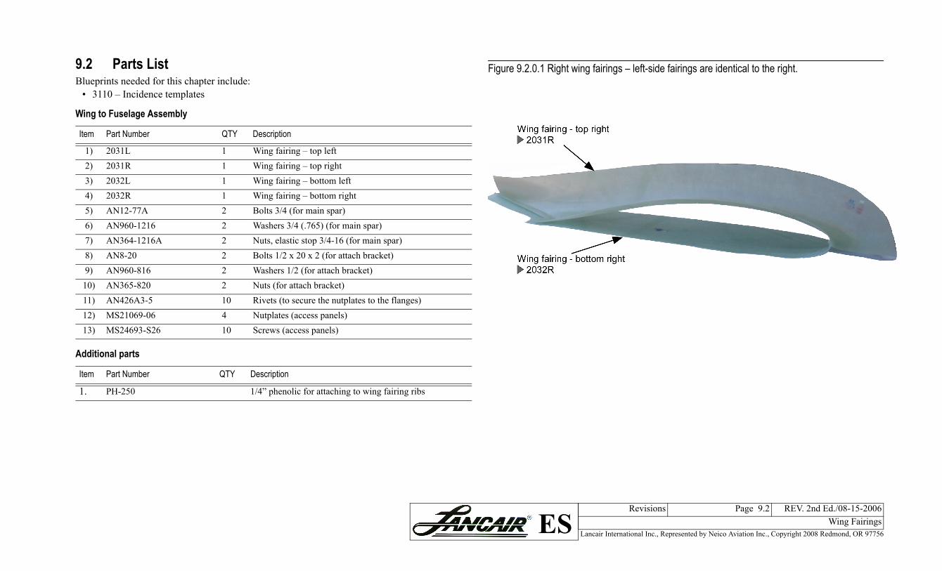
re 9.2.0.1 Right wing fairings – left-side fairings are identical to the right.
9.2 Parts ListBlueprints needed for this chapter include:• 3110 – Incidence templates
Wing to Fuselage Assembly
Item Part Number QTY Description
1) 2031L 1 Wing fairing – top left2) 2031R 1 Wing fairing – top right3) 2032L 1 Wing fairing – bottom left4) 2032R 1 Wing fairing – bottom right5) AN12-77A 2 Bolts 3/4 (for main spar)6) AN960-1216 2 Washers 3/4 (.765) (for main spar)7) AN364-1216A 2 Nuts, elastic stop 3/4-16 (for main spar)8) AN8-20 2 Bolts 1/2 x 20 x 2 (for attach bracket)9) AN960-816 2 Washers 1/2 (for attach bracket)
10) AN365-820 2 Nuts (for attach bracket)11) AN426A3-5 10 Rivets (to secure the nutplates to the flanges)12) MS21069-06 4 Nutplates (access panels)13) MS24693-S26 10 Screws (access panels)
Additional parts
Item Part Number QTY Description
1. PH-250 1/4” phenolic for attaching to wing fairing ribs
Figu
Lancair International Inc., Represented by Neico Aviation Inc., Copyright 2008 Redmond, OR 97756
Chapter 9 Page 9.3 REV. 2nd Ed./08-15-2006Wing FairingsES
9.3 Construction Procedures
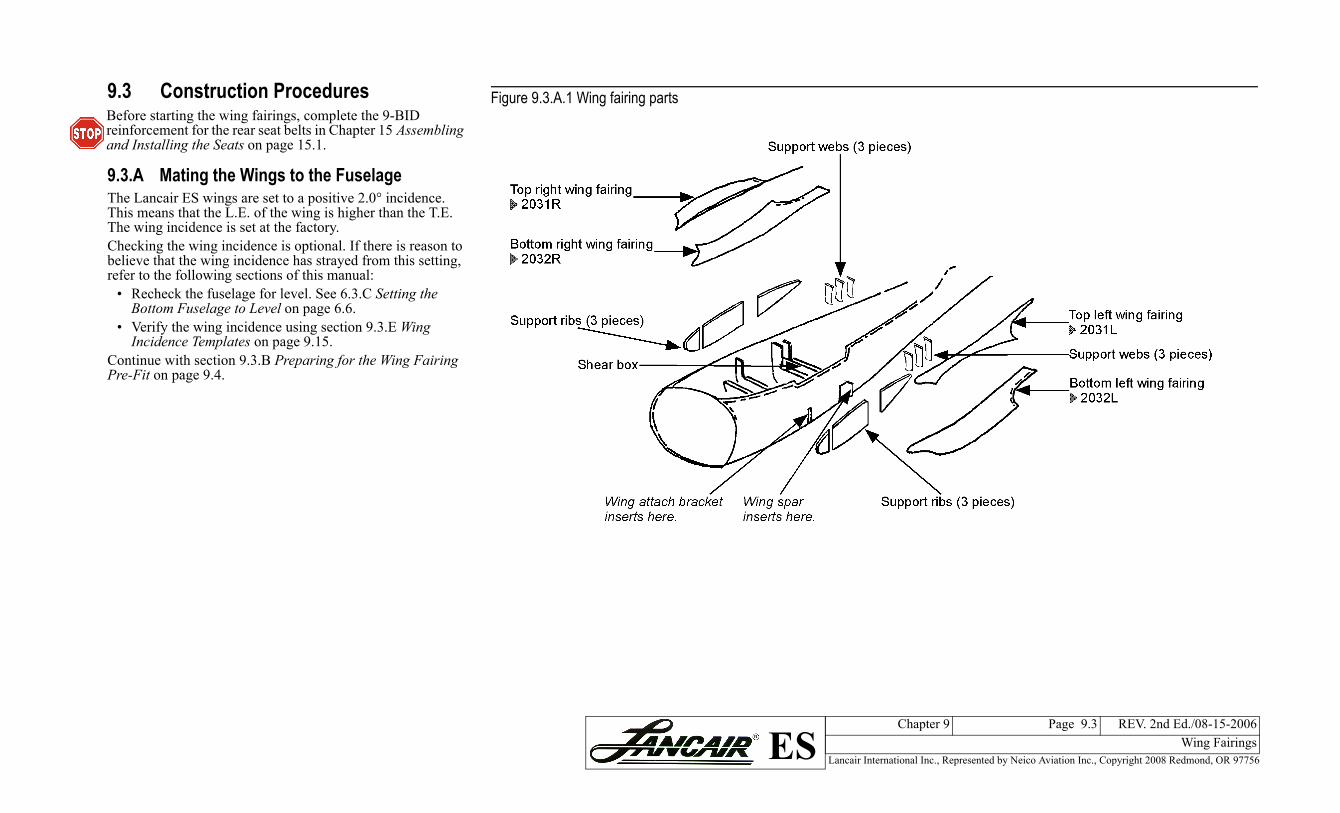
9.3.A Mating the Wings to the FuselageThe Lancair ES wings are set to a positive 2.0° incidence. This means that the L.E. of the wing is higher than the T.E. The wing incidence is set at the factory.Checking the wing incidence is optional. If there is reason to believe that the wing incidence has strayed from this setting, refer to the following sections of this manual:
• Recheck the fuselage for level. See 6.3.C Setting the Bottom Fuselage to Level on page 6.6.
• Verify the wing incidence using section 9.3.E Wing Incidence Templates on page 9.15.
Continue with section 9.3.B Preparing for the Wing Fairing Pre-Fit on page 9.4.
Before starting the wing fairings, complete the 9-BID reinforcement for the rear seat belts in Chapter 15 Assembling and Installing the Seats on page 15.1.
Figure 9.3.A.1 Wing fairing parts
Lancair International Inc., Represented by Neico Aviation Inc., Copyright 2008 Redmond, OR 97756
Chapter 9 Page 9.4 REV. 2nd Ed./08-15-2006Wing FairingsES
selage
f flap and wingWing inboard edge
9.3.B Preparing for the Wing Fairing Pre-FitIn this section the wings are installed so you can perform a pre-fit of aligning the wing fairings to the fuselage.
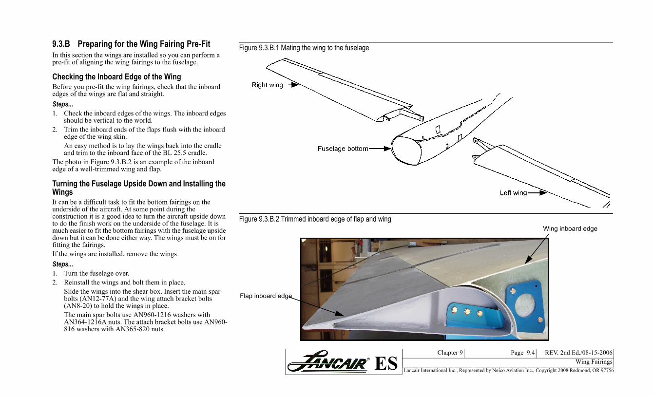
Checking the Inboard Edge of the WingBefore you pre-fit the wing fairings, check that the inboard edges of the wings are flat and straight.Steps...1. Check the inboard edges of the wings. The inboard edges
should be vertical to the world.2. Trim the inboard ends of the flaps flush with the inboard
edge of the wing skin.An easy method is to lay the wings back into the cradle and trim to the inboard face of the BL 25.5 cradle.
The photo in Figure 9.3.B.2 is an example of the inboard edge of a well-trimmed wing and flap.
Turning the Fuselage Upside Down and Installing the WingsIt can be a difficult task to fit the bottom fairings on the underside of the aircraft. At some point during the construction it is a good idea to turn the aircraft upside down to do the finish work on the underside of the fuselage. It is much easier to fit the bottom fairings with the fuselage upside down but it can be done either way. The wings must be on for fitting the fairings.If the wings are installed, remove the wingsSteps...1. Turn the fuselage over.2. Reinstall the wings and bolt them in place.
Slide the wings into the shear box. Insert the main spar bolts (AN12-77A) and the wing attach bracket bolts (AN8-20) to hold the wings in place.The main spar bolts use AN960-1216 washers with AN364-1216A nuts. The attach bracket bolts use AN960-816 washers with AN365-820 nuts.
Figure 9.3.B.1 Mating the wing to the fu
Figure 9.3.B.2 Trimmed inboard edge o
Flap inboard edge
Lancair International Inc., Represented by Neico Aviation Inc., Copyright 2008 Redmond, OR 97756
Chapter 9 Page 9.5 REV. 2nd Ed./08-15-2006Wing FairingsES
he top and bottom wing fairings
ent to the fuselage
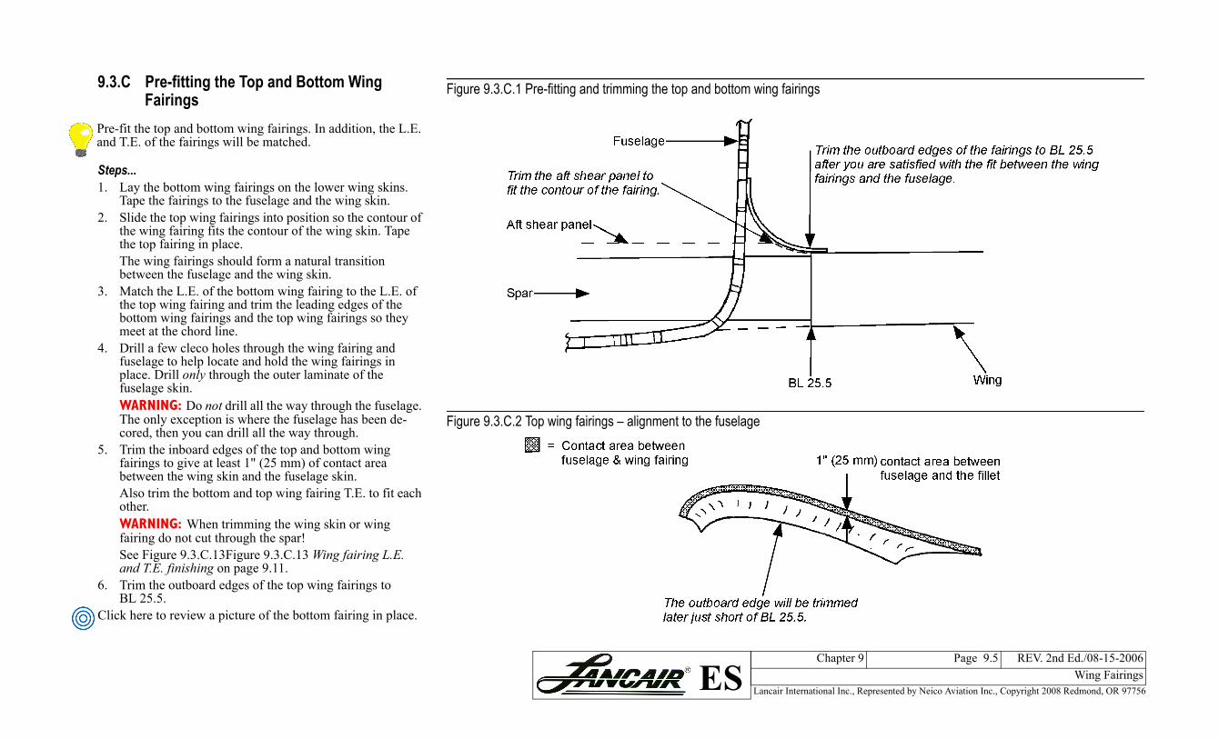
9.3.C Pre-fitting the Top and Bottom Wing Fairings
Steps...1. Lay the bottom wing fairings on the lower wing skins.
Tape the fairings to the fuselage and the wing skin.2. Slide the top wing fairings into position so the contour of
the wing fairing fits the contour of the wing skin. Tape the top fairing in place.The wing fairings should form a natural transition between the fuselage and the wing skin.
3. Match the L.E. of the bottom wing fairing to the L.E. of the top wing fairing and trim the leading edges of the bottom wing fairings and the top wing fairings so they meet at the chord line.
4. Drill a few cleco holes through the wing fairing and fuselage to help locate and hold the wing fairings in place. Drill only through the outer laminate of the fuselage skin.WARNING: Do not drill all the way through the fuselage. The only exception is where the fuselage has been de-cored, then you can drill all the way through.
5. Trim the inboard edges of the top and bottom wing fairings to give at least 1" (25 mm) of contact area between the wing skin and the fuselage skin.Also trim the bottom and top wing fairing T.E. to fit each other.WARNING: When trimming the wing skin or wing fairing do not cut through the spar! See Figure 9.3.C.13Figure 9.3.C.13 Wing fairing L.E. and T.E. finishing on page 9.11.
6. Trim the outboard edges of the top wing fairings to BL 25.5.
Click here to review a picture of the bottom fairing in place.
Pre-fit the top and bottom wing fairings. In addition, the L.E. and T.E. of the fairings will be matched.
Figure 9.3.C.1 Pre-fitting and trimming t
Figure 9.3.C.2 Top wing fairings – alignm
Lancair International Inc., Represented by Neico Aviation Inc., Copyright 2008 Redmond, OR 97756
Chapter 9 Page 9.6 REV. 2nd Ed./08-15-2006Wing FairingsES
ings to the wing skin at BL 25.5
fairings
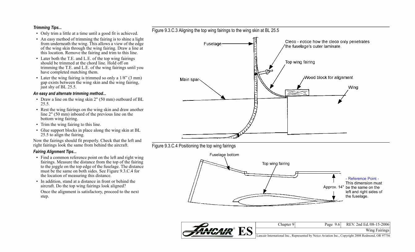
Trimming Tips...• Only trim a little at a time until a good fit is achieved.• An easy method of trimming the fairing is to shine a light
from underneath the wing. This allows a view of the edge of the wing skin through the wing fairing. Draw a line at this location. Remove the fairing and trim to this line.
• Later both the T.E. and L.E. of the top wing fairings should be trimmed at the chord line. Hold off on trimming the T.E. and L.E. of the wing fairings until you have completed matching them.
• Later the wing fairing is trimmed so only a 1/8” (3 mm) gap exists between the wing skin and the wing fairing, just shy of BL 25.5.
An easy and alternate trimming method...• Draw a line on the wing skin 2" (50 mm) outboard of BL
25.5.• Rest the wing fairings on the wing skin and draw another
line 2" (50 mm) inboard of the previous line on the bottom wing fairing.
• Trim the wing fairing to this line.• Glue support blocks in place along the wing skin at BL
25.5 to align the fairing.Now the fairings should fit properly. Check that the left and right fairings look the same from behind the aircraft.Fairing Alignment Tips...
• Find a common reference point on the left and right wing fairings. Measure the distance from the top of the fairing to the joggle on the top edge of the fuselage. The distance must be the same on both sides. See Figure 9.3.C.4 for the location of measuring this distance.
• In addition, stand at a distance in front or behind the aircraft. Do the top wing fairings look aligned?Once the alignment is satisfactory, proceed to the next step.
Figure 9.3.C.3 Aligning the top wing fair
Figure 9.3.C.4 Positioning the top wing
Lancair International Inc., Represented by Neico Aviation Inc., Copyright 2008 Redmond, OR 97756
Revisions Page 9.7 REV. 2nd Ed./08-15-2006Wing FairingsES
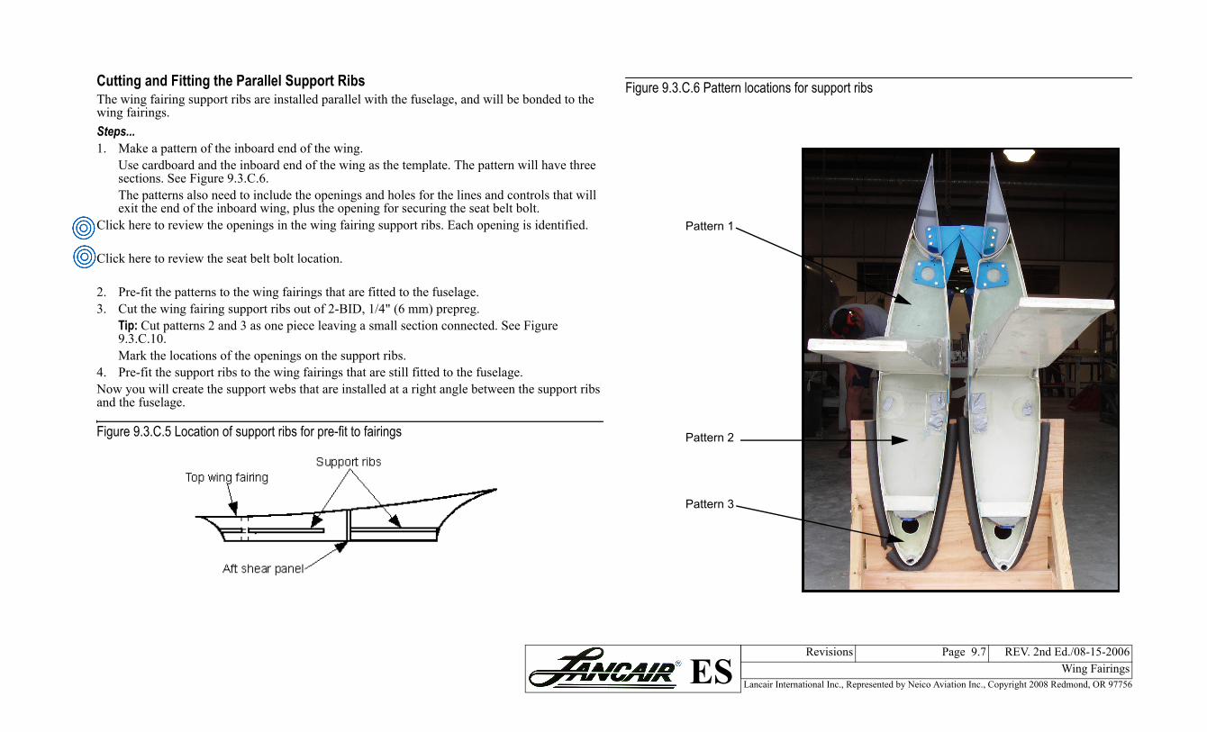
re 9.3.C.6 Pattern locations for support ribs
Pattern 1
Pattern 2
Pattern 3
Cutting and Fitting the Parallel Support RibsThe wing fairing support ribs are installed parallel with the fuselage, and will be bonded to the wing fairings.Steps...1. Make a pattern of the inboard end of the wing.
Use cardboard and the inboard end of the wing as the template. The pattern will have three sections. See Figure 9.3.C.6.The patterns also need to include the openings and holes for the lines and controls that will exit the end of the inboard wing, plus the opening for securing the seat belt bolt.
Click here to review the openings in the wing fairing support ribs. Each opening is identified.
Click here to review the seat belt bolt location.
2. Pre-fit the patterns to the wing fairings that are fitted to the fuselage.3. Cut the wing fairing support ribs out of 2-BID, 1/4" (6 mm) prepreg.
Tip: Cut patterns 2 and 3 as one piece leaving a small section connected. See Figure 9.3.C.10.Mark the locations of the openings on the support ribs.
4. Pre-fit the support ribs to the wing fairings that are still fitted to the fuselage.Now you will create the support webs that are installed at a right angle between the support ribs and the fuselage.
Figure 9.3.C.5 Location of support ribs for pre-fit to fairings
Figu
Lancair International Inc., Represented by Neico Aviation Inc., Copyright 2008 Redmond, OR 97756
Chapter 9 Page 9.8 REV. 2nd Ed./08-15-2006Wing FairingsES
placement
web
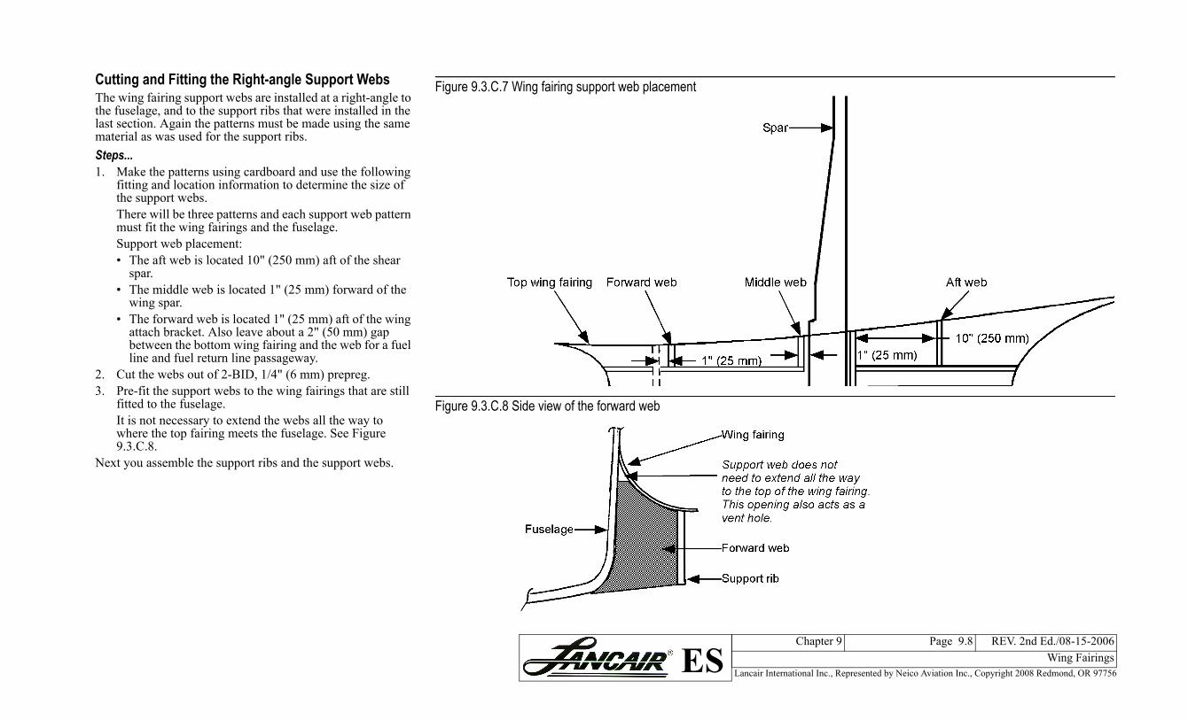
Cutting and Fitting the Right-angle Support WebsThe wing fairing support webs are installed at a right-angle to the fuselage, and to the support ribs that were installed in the last section. Again the patterns must be made using the same material as was used for the support ribs.Steps...1. Make the patterns using cardboard and use the following
fitting and location information to determine the size of the support webs.There will be three patterns and each support web pattern must fit the wing fairings and the fuselage.Support web placement:• The aft web is located 10" (250 mm) aft of the shear
spar.• The middle web is located 1" (25 mm) forward of the
wing spar.• The forward web is located 1" (25 mm) aft of the wing
attach bracket. Also leave about a 2" (50 mm) gap between the bottom wing fairing and the web for a fuel line and fuel return line passageway.
2. Cut the webs out of 2-BID, 1/4" (6 mm) prepreg. 3. Pre-fit the support webs to the wing fairings that are still
fitted to the fuselage.It is not necessary to extend the webs all the way to where the top fairing meets the fuselage. See Figure 9.3.C.8.
Next you assemble the support ribs and the support webs.
Figure 9.3.C.7 Wing fairing support web
Figure 9.3.C.8 Side view of the forward
Lancair International Inc., Represented by Neico Aviation Inc., Copyright 2008 Redmond, OR 97756
Chapter 9 Page 9.9 REV. 2nd Ed./08-15-2006Wing FairingsES
ibs and webs
ready to install
Assembling the Support Ribs and Webs
Steps...1. Remove between 1/8" to 1/4" of core around the
perimeter of each rib and web.2. Prepare all bonding surfaces for the BID tape that will
secure the ribs and webs.3. Pre-fit each web to the fuselage and the wing fairings.
Figure 9.3.C.9 provides a view of the completed support ribs and webs when assembled on your work table.
4. Fill one end of each support web’s de-cored edge with micro.
5. Install the filled end of the webs to the ribs with a thick epoxy/micro mixture.
6. Secure the support webs to the support ribs using a 2” (50 mm) wide 2-BID along each rib-to-web inside joint. Refer to Figure 9.3.C.9.
When you are done, you should have two pieces.• The forward and middle support ribs with the forward
and middle support webs attached.• A support rib with the aft support web attached.
See Figure 9.3.C.10 as a reference.
In this section you will assemble the support ribs and webs on a table. As you work, pre-fit often. After each web is bonded to a rib, pre-fit to the fuselage.
Figure 9.3.C.9 Assembling the support r
Figure 9.3.C.10 Support ribs and webs

Lancair International Inc., Represented by Neico Aviation Inc., Copyright 2008 Redmond, OR 97756
Chapter 9 Page 9.10 REV. 2nd Ed./08-15-2006Wing FairingsES
to fuselage and wing web.o fuselage and wing de of web.selage and wing fairing eblage’s shear panel with 4-
nto the support rib and 1" .C.11Figure 9.3.C.11.
he support rib with 4-BID
Figure 9.3.C.12 Side view –securing support ribs with 2-BID
Installing the Ribs-and-Webs PiecesSteps...1. Bond the support ribs and webs pieces in place with a
thick epoxy/micro mixture.It is important that the support ribs are vertical, and will be parallel to the center line of the fuselage. If a fuselage center line needs to be set, see Chapter 6 Fitting the Top Fuselage Shell on page 6.1.
2. Secure the support ribs to the top wing fairings with 2" (50 mm) wide 2-BID along both the inboard and outboard edges. See Figure 9.3.C.12.
Bonding the Top FairingsSteps...1. Remove the top fairings.2. Prepare all the bonding surfaces of the top fairings and
the fuselage.Make sure you sand the wing fairings where the support ribs and webs will be bonded.
3. Remove from 1/8" to 1/4" (3-6 mm) of core in the bottom of the wing fairings.
4. Put the top wing fairings back in place. Hold the wing fairings in place by gluing wood blocks between the wing skin and the wing fairings.Go easy on the instant glue when securing the wood blocks to the wing fairings since the wing fairings will need to be removed one last time.
Click here to review the wood shims used to hold the wing skins and the wing fairings in place.5. Check the alignment of the left and right top wing
fairings.Before the wing fairings are bonded in place, check that the left and right sides are correctly aligned.
6. Bond the top wing fairings to the fuselage with a thick epoxy/flox mixture.
• Forward support web – securefairing with BID on aft side of
• Middle support web – secure tfairing with BID on forward si
• Aft support web – secure to fuwith BID on forward side of w
3. Secure the support rib to the fuseBID.The 4-BID extends 1" (25 mm) oonto the fuselage. See Figure 9.3
Figure 9.3.C.11 Top view of securing t
Lancair International Inc., Represented by Neico Aviation Inc., Copyright 2008 Redmond, OR 97756
Chapter 9 Page 9.11 REV. 2nd Ed./08-15-2006Wing FairingsES
.E. finishing
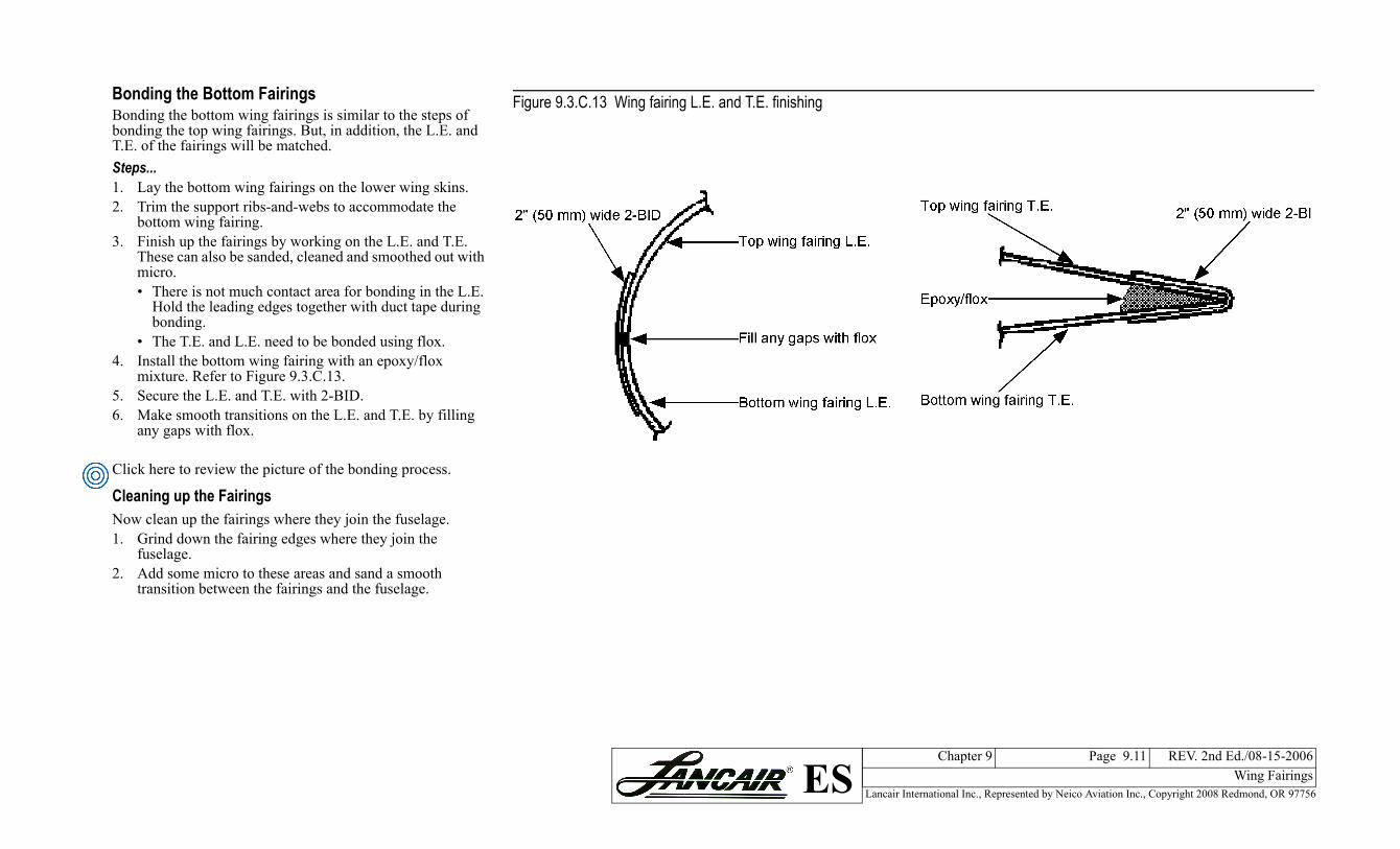
Bonding the Bottom FairingsBonding the bottom wing fairings is similar to the steps of bonding the top wing fairings. But, in addition, the L.E. and T.E. of the fairings will be matched.Steps...1. Lay the bottom wing fairings on the lower wing skins.2. Trim the support ribs-and-webs to accommodate thebottom wing fairing.3. Finish up the fairings by working on the L.E. and T.E.
These can also be sanded, cleaned and smoothed out with micro.• There is not much contact area for bonding in the L.E.
Hold the leading edges together with duct tape during bonding.
• The T.E. and L.E. need to be bonded using flox.4. Install the bottom wing fairing with an epoxy/flox
mixture. Refer to Figure 9.3.C.13.5. Secure the L.E. and T.E. with 2-BID.6. Make smooth transitions on the L.E. and T.E. by filling
any gaps with flox.
Click here to review the picture of the bonding process.
Cleaning up the FairingsNow clean up the fairings where they join the fuselage.1. Grind down the fairing edges where they join the
fuselage.2. Add some micro to these areas and sand a smooth
transition between the fairings and the fuselage.
Figure 9.3.C.13 Wing fairing L.E. and T
Lancair International Inc., Represented by Neico Aviation Inc., Copyright 2008 Redmond, OR 97756
Chapter 9 Page 9.12 REV. 2nd Ed./08-15-2006Wing FairingsES
e phenolic hardpoint
nt
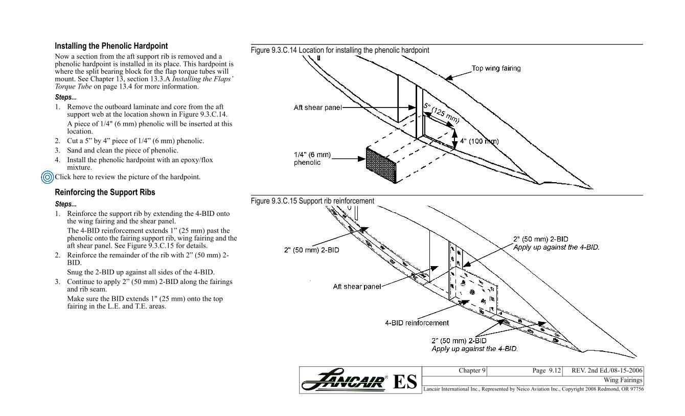
Installing the Phenolic HardpointNow a section from the aft support rib is removed and a phenolic hardpoint is installed in its place. This hardpoint is where the split bearing block for the flap torque tubes will mount. See Chapter 13, section 13.3.A Installing the Flaps’ Torque Tube on page 13.4 for more information.Steps...1. Remove the outboard laminate and core from the aft
support web at the location shown in Figure 9.3.C.14.A piece of 1/4" (6 mm) phenolic will be inserted at this location.
2. Cut a 5” by 4” piece of 1/4” (6 mm) phenolic. 3. Sand and clean the piece of phenolic.4. Install the phenolic hardpoint with an epoxy/flox
mixture.Click here to review the picture of the hardpoint.
Reinforcing the Support RibsSteps...1. Reinforce the support rib by extending the 4-BID onto
the wing fairing and the shear panel.The 4-BID reinforcement extends 1” (25 mm) past the phenolic onto the fairing support rib, wing fairing and the aft shear panel. See Figure 9.3.C.15 for details.
2. Reinforce the remainder of the rib with 2” (50 mm) 2-BID.Snug the 2-BID up against all sides of the 4-BID.
3. Continue to apply 2” (50 mm) 2-BID along the fairings and rib seam. Make sure the BID extends 1" (25 mm) onto the top fairing in the L.E. and T.E. areas.
Figure 9.3.C.14 Location for installing th
Figure 9.3.C.15 Support rib reinforceme
Lancair International Inc., Represented by Neico Aviation Inc., Copyright 2008 Redmond, OR 97756
Chapter 9 Page 9.13 REV. 2nd Ed./08-15-2006Wing FairingsES
l and opening locations
fairing access panel cutout for the fuel lines
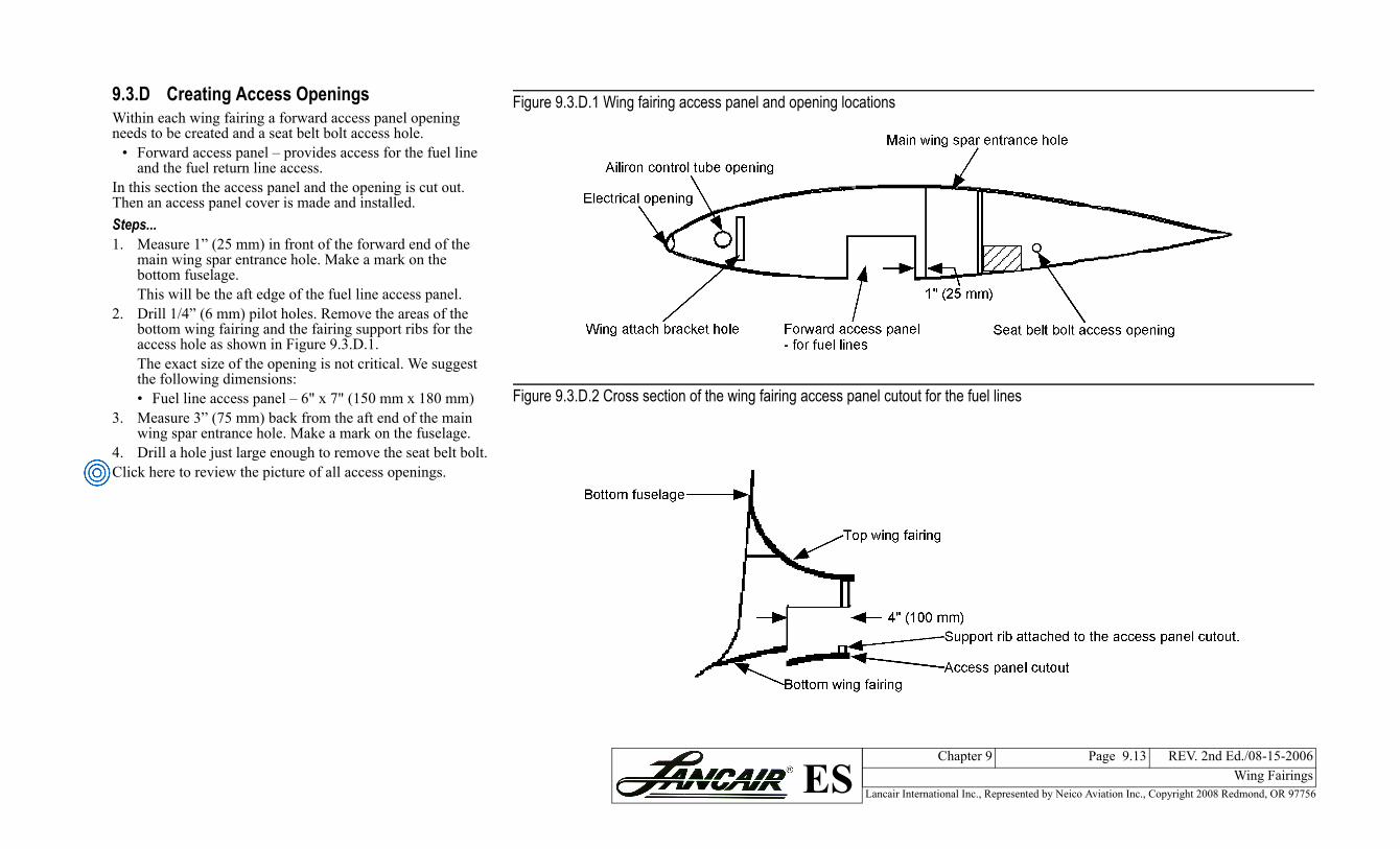
9.3.D Creating Access OpeningsWithin each wing fairing a forward access panel opening needs to be created and a seat belt bolt access hole.
• Forward access panel – provides access for the fuel line and the fuel return line access.
In this section the access panel and the opening is cut out. Then an access panel cover is made and installed. Steps...1. Measure 1” (25 mm) in front of the forward end of the
main wing spar entrance hole. Make a mark on the bottom fuselage.This will be the aft edge of the fuel line access panel.
2. Drill 1/4” (6 mm) pilot holes. Remove the areas of the bottom wing fairing and the fairing support ribs for the access hole as shown in Figure 9.3.D.1.The exact size of the opening is not critical. We suggest the following dimensions:• Fuel line access panel – 6" x 7" (150 mm x 180 mm)
3. Measure 3” (75 mm) back from the aft end of the main wing spar entrance hole. Make a mark on the fuselage.
4. Drill a hole just large enough to remove the seat belt bolt.Click here to review the picture of all access openings.
Figure 9.3.D.1 Wing fairing access pane
Figure 9.3.D.2 Cross section of the wing
Lancair International Inc., Represented by Neico Aviation Inc., Copyright 2008 Redmond, OR 97756
Chapter 9 Page 9.14 REV. 2nd Ed./08-15-2006Wing FairingsES
lange
el
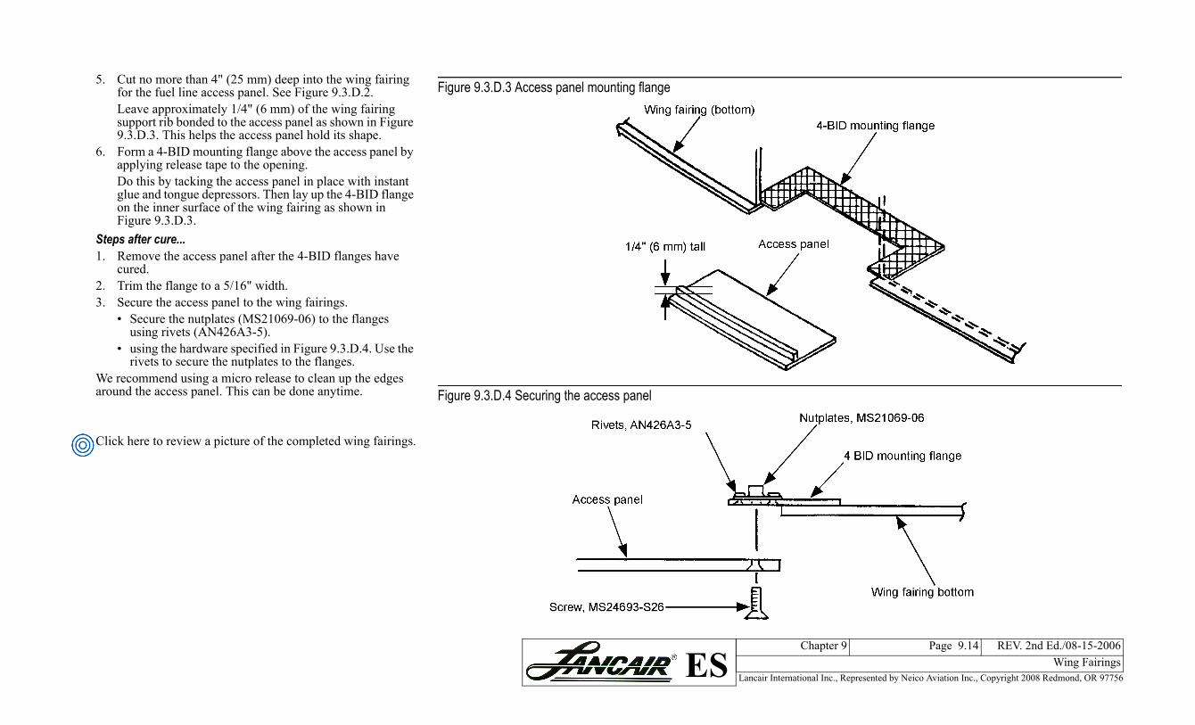
5. Cut no more than 4" (25 mm) deep into the wing fairing for the fuel line access panel. See Figure 9.3.D.2. Leave approximately 1/4" (6 mm) of the wing fairing support rib bonded to the access panel as shown in Figure 9.3.D.3. This helps the access panel hold its shape.
6. Form a 4-BID mounting flange above the access panel by applying release tape to the opening.Do this by tacking the access panel in place with instant glue and tongue depressors. Then lay up the 4-BID flange on the inner surface of the wing fairing as shown in Figure 9.3.D.3.
Steps after cure...1. Remove the access panel after the 4-BID flanges have
cured.2. Trim the flange to a 5/16" width.3. Secure the access panel to the wing fairings.
• Secure the nutplates (MS21069-06) to the flanges using rivets (AN426A3-5).
• using the hardware specified in Figure 9.3.D.4. Use the rivets to secure the nutplates to the flanges.
We recommend using a micro release to clean up the edges around the access panel. This can be done anytime.
Click here to review a picture of the completed wing fairings.
Figure 9.3.D.3 Access panel mounting f
Figure 9.3.D.4 Securing the access pan
Lancair International Inc., Represented by Neico Aviation Inc., Copyright 2008 Redmond, OR 97756
Chapter 9 Page 9.15 REV. 2nd Ed./08-15-2006Wing FairingsES
te
template to the wing
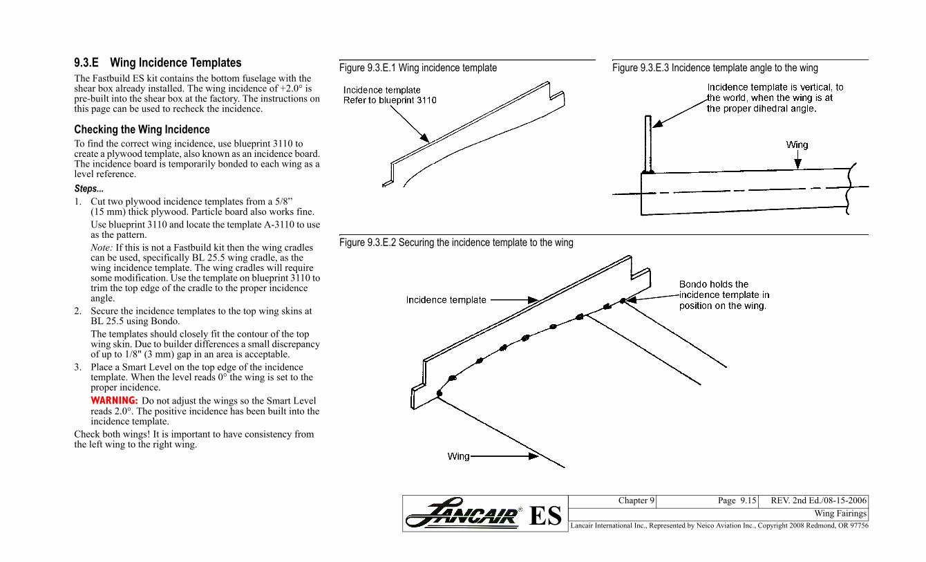
Figure 9.3.E.3 Incidence template angle to the wing
BL 25.5 using Bondo.The templates should closewing skin. Due to builder dof up to 1/8" (3 mm) gap in
3. Place a Smart Level on thetemplate. When the level rproper incidence.WARNING: Do not adjust reads 2.0°. The positive inincidence template.
Check both wings! It is importthe left wing to the right wing.
Templatesns the bottom fuselage with the
. The wing incidence of +2.0° is at the factory. The instructions on heck the incidence.
encecidence, use blueprint 3110 to also known as an incidence board. porarily bonded to each wing as a
ence templates from a 5/8” . Particle board also works fine. locate the template A-3110 to use
stbuild kit then the wing cradles y BL 25.5 wing cradle, as the te. The wing cradles will require the template on blueprint 3110 to cradle to the proper incidence
mplates to the top wing skins at
ly fit the contour of the top ifferences a small discrepancy an area is acceptable. top edge of the incidence eads 0° the wing is set to the
the wings so the Smart Level cidence has been built into the
ant to have consistency from
Figure 9.3.E.1 Wing incidence templa
Figure 9.3.E.2 Securing the incidence
9.3.E Wing IncidenceThe Fastbuild ES kit contaishear box already installedpre-built into the shear boxthis page can be used to rec
Checking the Wing IncidTo find the correct wing increate a plywood template, The incidence board is temlevel reference. Steps...1. Cut two plywood incid
(15 mm) thick plywoodUse blueprint 3110 andas the pattern.Note: If this is not a Facan be used, specificallwing incidence templasome modification. Usetrim the top edge of theangle.
2. Secure the incidence te