chapter – 3 hydraulic turbine …...53 chapter – 3 hydraulic turbine classification and...
TRANSCRIPT

53
CHAPTER – 3
HYDRAULIC TURBINE CLASSIFICATION AND SELECTION 3.1 Introduction (Reaction Turbines)
The hydraulic turbine is a mechanical device that converts the potential energy contained in an elevated body of water (a river or reservoir) into rotational mechanical energy. Selecting the type, kind, (within type) configuration, (horizontal or vertical) size, and number of turbine units that best suit a project is a detailed process. Size and number of units are discussed in chapter-2. This involves technical, environmental, financial, and other considerations. The most inexpensive turbine may not be the best solution to the available head and flow. For small hydro up to 5 MW units size standard turbines are recommended. For units above 5 MW size information exchange with turbine manufacturers is recommended for turbine selection at project stage. The selection procedure is prepared for selection of turbine based on the techno economic consideration to permit rapid selection of proper turbine unit, estimation of its major dimensions and prediction of its performance.-
3.2 Site Data It is presumed that the data with regard to design head (Para 3.2.2) design discharge, number and types of units and capacity are known. Departure from these guidelines for selection etc. as discussed may be necessary to meet the special requirements and conditions of individual sites.
3.2.1 Net Head
The effective head available to the turbine unit for power production is called the net head. Selection of rated and design head requires special attention in reaction turbines. Definition of these heads are given in Para 3.2.2. The turbine rating is given at rated head.
Determination of rated head, design head and maximum and minimum net head is important. Permissible departure from design head for reaction turbines for optimum efficiency and cavitation characteristics based on experience data is shown in table 3.1.
3.2.2 Definition of Head
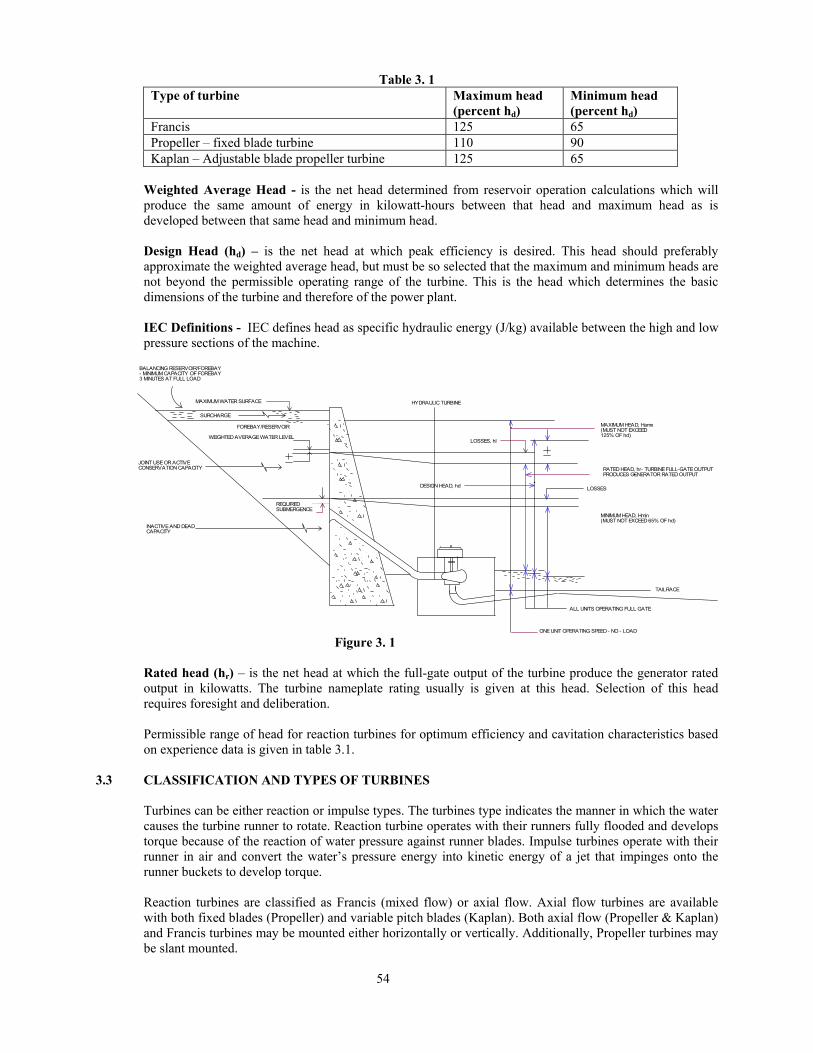
EFFECTIVE HEAD (Net Head) - The effective head is the net head available to the turbine unit for power production. This head is the static gross head, the difference between the level of water in the Forebay/impoundment and the tailrace water level at the outlet, less the hydraulic losses of the water passage as shown in Figure 3. 1. The effective head must be used for all power calculations. The hydraulic losses can vary from essentially zero for flume-type turbine installations to amounts so significant for undersized outlet conduit that the energy potential of the site is seriously restricted. The hydraulic losses in closed conduit can be calculated using the principles set out in general hydraulic textbooks. In addition to conduit losses, an allowance for a loss through the intake structure should also be included. In general a hydraulic loss of one velocity head (velocity squared divided by 2 x acceleration due to gravity) or greater would not be uncommon. The hydraulic losses through the turbine and draft tube are accounted for in the turbine efficiency. Gross Head (Hg) – is the difference in elevation between the water levels of the forebay and the tailrace.
Maximum Head (Hmax.) – is the gross head difference in elevation between the maximum forebay (head water) level without surcharge and the tailrace level without spillway discharge, and with one unit operating at speed no-load (turbine discharge of approximately 5% of rated flow). Under this condition, hydraulic losses are negligible and may be disregarded.
Minimum Head (Hmin.) – is the net head resulting from the difference in elevation between the minimum forebay (head water) level and the tailrace level minus losses with all turbines operating at full specified gate opening.
54
Table 3. 1 Type of turbine Maximum head
(percent hd) Minimum head (percent hd)
Francis 125 65 Propeller – fixed blade turbine 110 90 Kaplan – Adjustable blade propeller turbine 125 65
Weighted Average Head - is the net head determined from reservoir operation calculations which will produce the same amount of energy in kilowatt-hours between that head and maximum head as is developed between that same head and minimum head.
Design Head (hd) – is the net head at which peak efficiency is desired. This head should preferably approximate the weighted average head, but must be so selected that the maximum and minimum heads are not beyond the permissible operating range of the turbine. This is the head which determines the basic dimensions of the turbine and therefore of the power plant.
IEC Definitions - IEC defines head as specific hydraulic energy (J/kg) available between the high and low pressure sections of the machine.
MAXIMUM WATER SURFACE
FOREBAY/RESERVOIR
SURCHARGE
JOINT USE OR ACTIVECONSERVATION CAPACITY
INACTIVE AND DEADCAPACITY
REQUIREDSUBMERGENCE
WEIGHTED AVERAGE WATER LEVEL
MAXIMUM HEAD, Hamx(MUST NOT EXCEED125% OF hd)
RATED HEAD, hr- TURBINE FULL-GATE OUTPUTPRODUCES GENERATOR RATED OUTPUT
MINIMUM HEAD, Hmin(MUST NOT EXCEED 65% OF hd)
TAILRACE
ALL UNITS OPERATING FULL GATE
ONE UNIT OPERATING SPEED - NO - LOAD
DESIGN HEAD, hd
LOSSES, hl
LOSSES
HYDRAULIC TURBINE
BALANCING RESERVOIR/FOREBAY- MINIMUM CAPACITY OF FOREBAY3 MINUTES AT FULL LOAD
Figure 3. 1
Rated head (hr) – is the net head at which the full-gate output of the turbine produce the generator rated output in kilowatts. The turbine nameplate rating usually is given at this head. Selection of this head requires foresight and deliberation. Permissible range of head for reaction turbines for optimum efficiency and cavitation characteristics based on experience data is given in table 3.1.
3.3 CLASSIFICATION AND TYPES OF TURBINES Turbines can be either reaction or impulse types. The turbines type indicates the manner in which the water causes the turbine runner to rotate. Reaction turbine operates with their runners fully flooded and develops torque because of the reaction of water pressure against runner blades. Impulse turbines operate with their runner in air and convert the water’s pressure energy into kinetic energy of a jet that impinges onto the runner buckets to develop torque. Reaction turbines are classified as Francis (mixed flow) or axial flow. Axial flow turbines are available with both fixed blades (Propeller) and variable pitch blades (Kaplan). Both axial flow (Propeller & Kaplan) and Francis turbines may be mounted either horizontally or vertically. Additionally, Propeller turbines may be slant mounted.

55
3.3.1 Francis Turbines
A Francis turbine is one having a runner with fixed buckets (vanes), usually nine or more, to which the water enters the turbine in a radial direction, with respect to the shaft, and is discharged in an axial direction. Principal components consist of the runner, a water supply case to convey the water to the runner, wicket gates to control the quantity of water and distribute it equally to the runner and a draft tube to convey the water away from the turbines. It exists in large numbers throughout the world. It is applied at head ranges generally from about 15 to 750 meters and in power ranges from about 0.25 to 800 MW per unit. There are also numerous small units at very low heads. A Francis turbine may be operated over a range of flows approximately 40 to 105% of rated discharge. Below 40% rated discharge, there can be an area of operation where vibration and/or power surges occur. The upper limit generally corresponds to the generator rating. The approximate head range for operation is from 65% to 125% of design head. In general, peak efficiencies of Francis turbines, within the capacity range of 25 MW, with modern design tool like CFD (computational fluid dynamics) have enabled to achieve peak efficiency in the range of 93 to 94%. The conventional Francis turbine is provided with a wicket gate assembly to permit placing the unit on line at synchronous speed, to regulate load and speed, and to shutdown the unit. The mechanisms of large units are actuated by hydraulic servomotors. Small units may be actuated by electric motor gate operations. It permits operation of the turbine over the full range of flows. In special cases, where the flow rate is constant, Francis turbines without wicket gate mechanisms may be used. These units operate in case of generating units in Micro Hydro range (up to 100 kW) with Electronic Load Controller or Shunt Load Governors. Start up and shut down of turbines without a wicket gate is normally accomplished using the shut off valve at the turbine inlet. Synchronizing is done by manual load control to adjust speed.
Table 3.2: Indian Project Data of Francis Turbine Source: - Bharat Heavy Electrical Ltd. India Publication Entitled “Hydro-Electric
Installation” S. No
Power Station
Agency No. of units x size (MW)
Head (M)
Speed (RPM)
Year of Commissio
ning (expected)
Specific speed
Type of turbine
Specific speed Ns
marked in Figure
3.12 1. 2. 3. 4. 5. 6. 7. 8. 9. 10. 1. Nathpa Jakhri
(BHEL Unit) NJPC 1 x 250 428 300 2003 93.32 Vertical
Francis 52
2. Dehar BCB 6 x 165 282 300 1977 203.21 Vertical Francis
53
3. Pong BCB 6 x 60 65.5 166.7 1978 265.38 Vertical Francis
54
4. Chibro UPSEB 4 x 60 110 250 1975 208.18 Vertical Francis
55
5. Khodri UPSEB 4 x 30 57.9 200 1984 262.69 Vertical Francis
56
6. Khara UPSEB 3 x 24 42.6 187 1992 322.37 Vertical Francis
57
7. Khandong NEEPCO 2×25 99.0 333.3 1984 204.37 Vertical Francis
12
8. Kakkad KSEB 2×25 123.5 428.6 1999 199.34 Vertical Francis
13
9. Mahi Stage-I RSEB 2×25 40.0 150.0 1986 285.53 Vertical Francis
14
10. Doyang NEEPCO 3×25 67.0 250.0 2000 249.74 Vertical Francis
15
11. Khara UPSEB 3×24 42.6 187.0 1992 322.37 Vertical Francis
16

56
S. No
Power Station
Agency No. of units x size (MW)
Head (M)
Speed (RPM)
Year of Commissio
ning (expected)
Specific speed
Type of turbine
Specific speed Ns
marked in Figure
3.12 12. Pattani EGA
Thailand 3×24 58.0 214.3 1981 251.19 Vertical
Francis 17
13. Tenom Pangi SEB Malaysia
3×22 66.6 300.0 1983 283.24 Vertical Francis
18
14. Kundah-V TNEB 1×21.6 259.1 750.0 1988 128.42 Vertical Francis
19
15. Madhikheda MPEB 3×20 52.75 250.0 2005 301.19 Vertical Francis
20
16. Rangit NHPC 3×20 129.67 428.6 2000 167.76 Vertical Francis
21
17. Birsinghpur MPEB 1×20 40.0 200.0 1991 340.51 Vertical Francis
22
18. Poringal Kuthu
KSEB 1×16 165.3 600.0 1999 155.07 Vertical Francis
23
19. Bhatsa GOM 1×15 70.0 375.0 1991 274.71 Vertical Francis
24
20. Sumbal Sindh Govt. of J&K
2×11.3 149.0 500.0 1973 123.65 Vertical Francis
25
21. Gumma HPSEB 2×1.5 176.75 1500.0 2000 109.17 Vertical Francis
26
22. Karnah Govt. of J&K
2×1.0 36.0 750.0 1991 325.72 Vertical Francis
27
Francis turbines may be mounted with vertical or horizontal shafts. Vertical mounting allows a smaller plan area and permits a deeper setting of the turbine with respect to tailrace water elevation locating the generator below tailrace water. Turbine costs for vertical units are higher than for horizontal units because of the need for a larger thrust bearing. However, the savings on construction costs for medium and large units generally offset this equipment cost increase. Horizontal units are more economical for smaller sets with higher speed applications where standard horizontal generators are available. A typical horizontal axis Francis turbine is shown in figure 3.2. The water supply case is generally fabricated from steel plate. However open flume and concrete cases may be used for heads below 15 meters. Francis turbines are generally provided with a 90-degree elbow draft tube, which has a venturi design to minimize head loss. Conical draft tubes are also available, however the head loss will be higher and excavation may be more costly.
A list of typical large and small hydro projects with Francis turbines in the country manufactured/supplied by M/s Bharat heavy Electricals Ltd. (BHEL) – the largest manufactures of hydro electric equipment in the country is given in table 3.2.
A typical vertical Francis turbine transverse section of Bhakra Left Bank power plant (5 x 90MW) is shown in figure 3.3 (a) & figure 3.3 (b). This is the first large power house designed indigenously with the help of American consultants with imported machines and commissioned 1st unit in 1960. The power units were subsequently updated, renovated and modernized.
Provision for removing runner from below through an access gallery after removal of bottom cover for quick repair of excessive pitting, metal erosion, corrosion in case of presence of injurious elements in water is sometimes made.
3.3.2 Axial Flow Turbines Axial flow turbines are those in which water flow through the runner is aligned with the axis of rotation. Axial flow hydraulic turbines have been used for net heads up to 75 meters with power output up to 200

57
MW. However, they are generally used in head applications below 35 meters. Tubular turbines (S-type) are used below 30 meters head and 8 MW capacity. Bulb units can be used to about 25 meters head and up to about 100 MW capacity. In SHP Bulb units can be used for low heads if runner diameter is more than 1 meter. Specific mechanical designs, civil construction, and economic factors must be given full consideration when selecting among these three axial flow turbine arrangements. A Kaplan/propeller turbine is one having a runner with three, four, five or six blades in which the water passes through the runner in an axial direction with respect to the shaft. The pitch of the blades may be fixed or movable. Principal components consist of a water supply case, wicket gates, a runner and a draft tube. Axial flow turbine with movable blades is called Kaplan turbines. Axial flow turbines with fixed blades is called propeller turbine. An axial flow turbine with movable blades but fixed guide vanes (no wicket gates) is called semi Kaplan turbine.
Rated head : 103.345 m Runner diameter : 856 mm Type of turbine : Horizontal Francis Rated turbine/generator speed : 750 RPM Butterfly valve : Ø 1100
Figure 3.2: Horizontal Francis Turbine (4 x 4000 kW) Halaipani Project (Arunachal Pradesh)
(Source: AHEC Projects Data)

58
Figure 3.3 (a) Bhakra Left bank Power Plant No. 1 Transverse Section (1960) (Hitachi Turbines) (Dimensions in feet & inches) Turbine – Vertical Francis Type Max. head (m) Rated & Design Head (m) Min. head (m) Net Head (m) 156.06 121.92 87.79 Output (h.p.) 150,000 (112 MW) 150,000(112 MW) 71,000 (53 MW) Efficiency at 100% output 91.1% 91.1% 86.3% Discharge Rated M3/sec. 102.3 Speed r.p.m. 338 (runaway) 166.7 166.7 Runner Normal dia. (mm) 4157 No. of blades 17 Weight 29.46 (Tonnes) Setting Hs (ft.) - 1 Spiral Casing Inlet dia. mm 3962.4 Note: Unit Capacity after Renovation, Modernization and updating was increased to 108 MW and propose further updating to 126 MW.

59
Figure 3.3 (b): Bhakra Left Bank Francis Turbine (Section through Turbine)
(Source: Notes compiled from uprating as Member uprating committee)

60
The efficiency curve of a typical fixed blade Propeller turbine forms a sharp peak, more abrupt than a Francis turbine curve. For variable pitch blade units the peak efficiency occurs at different outputs depending on the blade setting. An envelope of the efficiency curves cover the range of blade pitch settings forms the variable pitch efficiency curve. This efficiency curve is broad and flat. Fixed blade units are less costly than variable pitch blade turbines; however, the power operating ranges are more limited. Turbine manufacturers have developed runner designs for a head range of 3 to 40 meters. Four blade designs may be used up to 12 meters of head, five blade designs to 20 meters and six blade designs to 35 meters. In general, peak efficiencies are approximately the same as for Francis turbines.
Kaplan turbines may be operated at power outputs with flow from 40-105% of the rated flow. Discharge rates above 105% may be obtained; however, the higher rates are generally above the turbine and generator manufacturers’ guarantees. Many units are in satisfactorily operation from 60 to 140% of design head. Efficiency loss at higher heads drops 2 to 5% points below peak efficiency at the design head and as much as 15% points at lower heads. Kaplan (variable pitch blade) turbines are mounted with a vertical shaft. Horizontal and slant settings will be discussed separately. The vertical units are equipped with a wicket gate assembly to permit placing the unit on line at synchronous speed, to regulate speed and load, and to shutdown the unit. The wicket gate mechanism units are actuated by hydraulic servomotors. Small units may be actuated by electric motor gate operators. Variable pitch units are equipped with a cam mechanism to coordinate the pitch of the blade with gate position and head. Digital control envisages Control of wicket gates and blade angle by independent servomotors coordinated by digital control. The special condition of constant flow, as previously discussed for Francis turbines, can be applied to propeller turbines. For this case, elimination of the wicket gate assembly may be acceptable. The advantage and disadvantages discussed above with regard to vertical versus horizontal settings for
Francis turbines apply also to propeller turbines. The water supply case is generally concrete. Either an open flume or a closed conduit type of construction may be used. Open flume construction may be economical when heads are below 13 meters. At higher heads the turbine shaft length becomes excessive. Also open flume construction is disadvantageous with regard to maintenance costs. The wicket gate assembly and guide bearing are water lubricated causing additional maintenance particularly when silt or debris is in the water
Table 3.3: Typical Indian Project Data of Kaplan/Propeller Turbine Source: - Bharat Heavy Electrical Ltd. India Publication Entitled “Hydro-Electric
Installation”
S. No
Power Station Agency No. of units x
size (MW)
Head (M)
Speed (RPM)
Year of Commissio
ning (expected)
Specific speed (Ns)
Type of turbine
Specific speed H
marked in Figure
3.12 1. 2. 3. 4. 5. 6. 7. 8. 9. 10.
1. Ukai GEB 4 x 75 47.8 150 1974 395.82 Vertical Kaplan
58
2. Sardar Sarovar (CHPH)
SSNNL 5 x 50 36 136.4 2004 418.88 59
3. Garhwal Risikesh Chilla
UPSEB 4 x 36 32.5 187.5 1980 555.22 60
4. Obra UPSEB 3 x 33 20.4 115.4 1970 285.59 61 5. Baliamela APSEB 2 x 30 35.8 187.5 2008 449.13 62 6. Balimela Dam APSEB 2×30 35.8 187.5 2008 449.13 28. 7. Donkarai APSEB 1×25 21.0 136.4 1983 580.99 29. 8. Mukerian Phase-
III & IV PSEB 6×19.5 22.0 166.7 1989 591.68 30.
9. SYL Phase-I PSEB 2×18 15.3 136.4 2010 732.41 31. 10. UBDC Stage-II PSEB 3×15 17.1 166.7 1989 711.05 32.

61
11. UBDC PSEB 3×15 17.1 150.0 1971 639.82 33. 12. Mukerian
Phase-I & II PSEB 6×15 16.8 150.0 1983 654.13 34.
13. Bansagar Phase-II
MPEB 2×15 21.0 166.7 2002 550.01 35.
14. Kabini SP&ML 2×10 18.0 200.0 2003 653.29 36. 15. Pochampad APSEB 3×9 21.4 250.0 1987 624.04 37. 16. Mukerian
Stage-II PSEB 2×9 8.23 125.0 2009 1030.26 Bulb
turbine 38.
17. Singur APSEB 2×7.5 18.29 250.0 1999 693.22 Vertical Kaplan
39.
18. Teesta Canal WBSEB 4×7.5 8.0 142.9 1999 1113.95 40. 19. Bhadra R.B. KPCL 1×6 17.0 214.0 1998 581.56 41. 20. Narayanpur MPCL 2×5.8 6.5 111.1 1999 987.31 42. 21. Suratgarh RSEB 2×2 8.66 187.5 1992 683.57 43. 22. Mangrol RSEB 3×2 7.27 166.7 1992 756.31 44. 23. Sone Western
Canal BSHPC 4×1.65 3.7 120.0 1993 1150.37 45.
24. Dhupdal FORBES Gokak Mills
2×1.4 4.8 158.0 1997 1107.71 46.
25. Nidampur PSEB 2×0.5 3.0 136.4 1985 935.54 Horizontal Propeller/Kaplan
47.
26. Dauhar PSEB 3×0.5 3.5 136.4 1987 771.58 48. 27. Ganekal KPCL 1×0.35 3.69 136.4 1994 604.27 49. 28. Kakatiya
(19th Mile) APSEB 3×0.23 3.3 166.7 1987 688.37 50.
29. Kakroi University of Roorkee
1×0.1 1.9 125.0 1988 678.63 51.
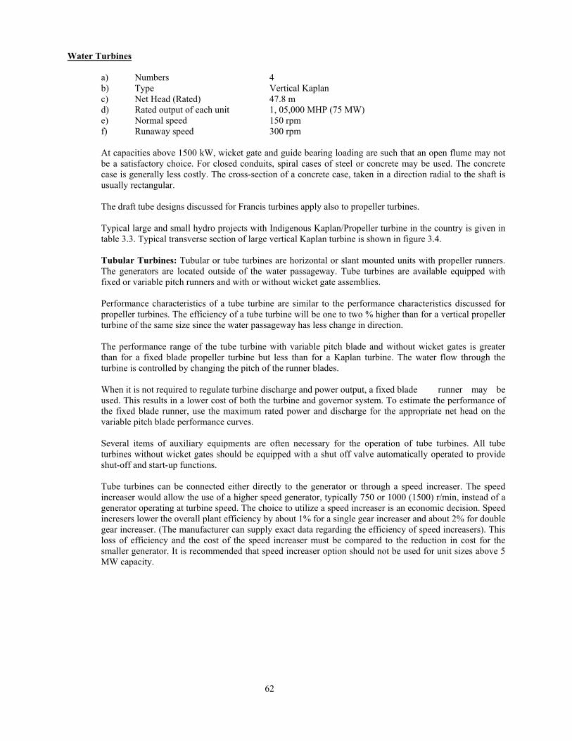
Figure 3.4: UKAI Power House – Transverse Section – Vertical Kaplan (Gujarat) (Source: CBI & P Publication No. 288))
62
Water Turbines
a) Numbers 4 b) Type Vertical Kaplan c) Net Head (Rated) 47.8 m d) Rated output of each unit 1, 05,000 MHP (75 MW) e) Normal speed 150 rpm f) Runaway speed 300 rpm
At capacities above 1500 kW, wicket gate and guide bearing loading are such that an open flume may not be a satisfactory choice. For closed conduits, spiral cases of steel or concrete may be used. The concrete case is generally less costly. The cross-section of a concrete case, taken in a direction radial to the shaft is usually rectangular. The draft tube designs discussed for Francis turbines apply also to propeller turbines. Typical large and small hydro projects with Indigenous Kaplan/Propeller turbine in the country is given in table 3.3. Typical transverse section of large vertical Kaplan turbine is shown in figure 3.4.
Tubular Turbines: Tubular or tube turbines are horizontal or slant mounted units with propeller runners. The generators are located outside of the water passageway. Tube turbines are available equipped with fixed or variable pitch runners and with or without wicket gate assemblies. Performance characteristics of a tube turbine are similar to the performance characteristics discussed for propeller turbines. The efficiency of a tube turbine will be one to two % higher than for a vertical propeller turbine of the same size since the water passageway has less change in direction. The performance range of the tube turbine with variable pitch blade and without wicket gates is greater than for a fixed blade propeller turbine but less than for a Kaplan turbine. The water flow through the turbine is controlled by changing the pitch of the runner blades. When it is not required to regulate turbine discharge and power output, a fixed blade runner may be used. This results in a lower cost of both the turbine and governor system. To estimate the performance of the fixed blade runner, use the maximum rated power and discharge for the appropriate net head on the variable pitch blade performance curves. Several items of auxiliary equipments are often necessary for the operation of tube turbines. All tube turbines without wicket gates should be equipped with a shut off valve automatically operated to provide shut-off and start-up functions. Tube turbines can be connected either directly to the generator or through a speed increaser. The speed increaser would allow the use of a higher speed generator, typically 750 or 1000 (1500) r/min, instead of a generator operating at turbine speed. The choice to utilize a speed increaser is an economic decision. Speed incresers lower the overall plant efficiency by about 1% for a single gear increaser and about 2% for double gear increaser. (The manufacturer can supply exact data regarding the efficiency of speed increasers). This loss of efficiency and the cost of the speed increaser must be compared to the reduction in cost for the smaller generator. It is recommended that speed increaser option should not be used for unit sizes above 5 MW capacity.

63
Figure 3.5 Typical Dimension of Tube Turbine (Source: BHEL India)
The required civil features are different for horizontal units than for vertical units. Horizontally mounted tube turbines require more floor area than vertically mounted units. The area required may be lessened by slant mounting, however, additional turbine costs are incurred as a large axial thrust bearing is required. Excavation and powerhouse height for a horizontal unit is less than that required for a vertical unit. Standard Tube turbines of Bharat Heavy Electricals based on runner diameter is shown in Figure 3.5. A large number of these turbines are installed in the country. First ultra low head (1.9 m) 100 kW tubular turbine indigenous made by (BHEL) on a branch canal was installed as an experimental measure to demonstrate economic viability of a large no. of such falls in the country. This is discussed in detail in chapter 13.
Bulb Turbines: Bulb Turbines are horizontal, axis having propeller runners directly connected to the generator. The generator is enclosed in a water-tight enclosure (bulb) located in the turbine water passageway. The bulb turbine is available with fixed or variable pitch blades and with or without a wicket gate mechanism. Performance characteristic are similar to the vertical and Tube type turbines previously discussed. The bulb turbine will have an improved efficiency of approximately 2% over a vertical unit and

64
1% over a tube unit because of the straight water passageway. Due to the compact design, powerhouse floor space and height for Bulb turbine installations are minimized. Maintenance time due to accessibility, however, may be greater than for either the vertical or the tube type turbines.
Figure 3.6 shows bulb turbine installation proposed for Mukerain SHP 2 x 9 MW at rated and design head 8.23 m.
Comparison between Vertical Kaplan and Horizontal Bulb -Water Passage: The main difference between the Bulb turbine and the vertical Kaplan turbine is the water passage. In case of a vertical turbine the direction of flow of the water changes several times, first in the spiral case, then in the space between guide vanes and runner and lastly in the draft tube for reaching the horizontal direction into the tail water. In case of a Bulb turbine the water passes the flow canal nearly straight lined. Strong changes in direction of flow are avoided by arranging the unit shaft horizontally or slightly inclined. From these differences in the two types of turbines many advantages in use of bulb turbines occur.
Hydraulic Features of Bulb Turbines: Due to the higher flow velocity in a Bulb turbine the hydraulic losses from the intake to the guide vanes are somewhat higher than those of a Kaplan turbine; this is the same for the inlet and outlet losses. However, the flow between guide vane and runner is nearly free of changes of direction and the draft tube efficiency due to the straight draft tube with a uniform velocity distribution at the outlet is more favourable than that of a Kaplan turbine. These advantages cause an improvement of the hydraulic efficiency of the bulb turbine at full discharge in the range of overload and compared with the Kaplan turbines a flatter efficiency curve is obtained.
Figure 3.6 Bulb Turbine for Mukerian SHP 2 x 9 MW
(Source: AHEC Specification)
The discharge of a bulb turbine is higher with the same efficiency than the discharge of Kaplan turbine. Comparisons shows that due to these reasons the bulb turbine can be designed with a runner diameter 15 percent smaller and be rated with a higher speed of 20-25 percent to reach the same output and efficiency as the Kaplan turbine at given technical data of the plant.
During one revolution each point of a runner blade of a Vertical Kaplan turbine moves in a Horizontal plane, that means under the same suction head and thus under the same cavitation conditions. In case of the horizontally arranged bulb turbine, however, one blade during one revolution passes several suction heads.

65
Caused by the changing cavitation along the runner diameter a periodic cavitation noise or periodic pressure fluctuations may occur. The most endangered range of cavitation is the periphery of the blades in its topmost position. Each blade, however, passes the range within a short time. With regard to economic reasons this extent of cavitation condition is permitted without impairing the operating conditions or endangering the turbine.
If a bulb turbine and a Vertical Kaplan turbine have the same velocity of flow in the runner, the cavitation behaviour of the bulb turbine is better. That means that either a higher installation or higher speed is possible with the same unit power.
Advantages in Civil Works: From the hydraulic conditions of bulb turbines considerable advantages result for the civil engineering. Turbine intake and draft tube are easy to form, the spiral can be completely omitted. The straight-lined design of the turbine inlet permits a reduction of the distance between the units of above 30 percent and thus saving in the width of the power plant. The longitudinal distance from the turbine inlet to the draft tube outlet is about the same as for vertical units. The height of the power plant can also be reduced. Besides the essentially reduced volume of civil work also the simple sheeting due to the omission of the elbows reduce the cost of civil works considerably.
Vertical Semi-Kaplan Turbine with Syphon Intake: These are Low specific speed Vertical semi-Kaplan
turbine set above maximum tailrace level with Syphon intake with adjustable runner blade and fixed guide vane. As the name suggests, the Vertical Turbine with Syphon Intake operates on the Syphon Principle i.e. the intake flume chamber valve is closed and made water tight and vacuum is created by a vacuum pump which enables water to enter flume chamber and energize the runner. Shut down is brought about by following the reverse procedure i.e. by breaking vacuum. Since turbine operates on a Syphon Principle, it is not necessary to have Intake and Draft gates thereby reducing the cost. The Syphon Intake semi Kaplan Vertical Turbine part load efficiency at about 30% load is about 76%. Turbine is suitable for variable head also. Dewatering and drainage arrangements are also not required.
This type of turbine has been found to be very economical for canal drop falls (up to 3-4 m head). The turbine is set above maximum tailrace water level and hence lower specific speed. A typical installation is shown in figure 3.7. A list of such typical installation is given in table 3.4.
Table 3. 4: Projects on canal falls with Vertical Semi Kaplan Turbines with Syphon Intakes (AHEC Project)
Sl. No
Power Station
Sponsorer/ Manufact
urer
No. of Units x
Size (MW)
Head (M)
Speed (RPM)
Year/ Likely year of
Commissioning
Specific Speed (Ns)
Type of Turbine
Type of Generator
BIHAR 1. Shirkhinda
SHP HPP Energy (India) Pvt. Ltd.
2x0.350 3.186
135 2010 744.89 Vertical Semi Kaplan with Syphon Intake
Synchronous Generator Vertical
2. Belsar SHP
HPP Energy (India) Pvt. Ltd.
2x0.500 3.22 129 Under commissioning/construction
763.22 Vertical Semi Kaplan with Syphon Intake
Synchronous Generator Vertical
3. Tejpura SHP
HPP Energy (India) Pvt. Ltd.
2x0.750 3.46 107 Under commissioning/construction
770.77 Vertical Semi Kaplan with Syphon Intake
Synchronous Generator Vertical
4. Rajapur SHP
HPP Energy (India) Pvt. Ltd.
2x0.350 4.78 190 Under commissioning/construction
798.55 Vertical Semi Kaplan with Intake Gate
Synchronous Generator Vertical
5. Amethi SHP
HPP Energy (India) Pvt. Ltd.
1x0.500 3.218
114 Under commissioning/construction
745.97 Vertical Semi Kaplan with Syphon Intake
Synchronous Generator Vertical
6. Arwal SHP
HPP Energy (India) Pvt. Ltd.
1x0.500 2.926
103 Under commissioning/construction
757.83 Vertical Semi Kaplan with Syphon Intake
Synchronous Generator Vertical
7. Walidad SHP
HPP Energy (India) Pvt. Ltd.
1x0.700 3.44 116 Under commissioning/construction
751.36 Vertical Semi Kaplan with Syphon Intake
Synchronous Generator Vertical

66
Figure 3.7- Syphon Intake for Tejpura project (AHEC Project)
Pit Type Bulb Turbine: Pit type turbine is a variation of S-type arrangements. Typical pit Turbines coupled to standard high speed generator through step up bevel/helical gears are generally used. Overall efficiency is lower because of gear box. Maximum size depends upon gear box and is generally limited to 5 MW. Higher sized unit up to 10 MW have been recently installed. Performance data of these units is not available. Typical installation is shown in figure 3.8(a) and figure 3.8 (b) 3.3.3 Impulse Turbine
Pelton Turbines: An impulse turbine is one having one or more free jets discharging into an aerated space
and impinging on the buckets of a runner. Efficiencies are often 90% and above. In general, an impulse turbine will not be competitive in cost with a reaction turbine in overlapping range. However, certain hydraulic conditions or surge protection requirements may warrant investigation into the suitability of an impulse turbine in the overlapping head range.
Single nozzle impulse pelton turbine has a very flat efficiency curve and may be operated down to loads of 20% of rated capacity with good efficiency. For multi-nozzle units, the range is even broader because the number of operating jets can be varied. Control of the turbine is maintained by hydraulically operated needle nozzles in each jet. In addition, a jet deflector is provided for emergency shutdown. The deflector diverts the water jet from the buckets to the wall of the pit liner. This feature provides surge protection for the penstock without the need for a pressure relief valve because load can be rapidly removed from the generator without changing the flow rate. Control of the turbine may also be accomplished by the deflector alone. On these units the needle nozzle is manually operated and the deflector diverts a portion of the jet for lower loads. This method is less efficient and normally used for speed regulation of the turbine under constant load. Runners on the modern impulse turbine are a one-piece casting. Runners with individually attached buckets have proved to be less dependable and, on occasion, have broken away from the wheel causing severe

67
damage to powerhouse. Integral cast runners are difficult to cast, costly and require long delivery times. However, maintenance costs for an impulse turbine are less than for a reaction turbine as they are free of cavitation problems. Excessive silt or sand in the water however, will cause more wear on the runner of an impulse turbine than on the runner of most reaction turbines. Draft tubes are not required for impulse turbines. The runner must be located above maximum tailrace water to permit operation at atmospheric pressure. This requirement entails an additional head loss for an impulse turbine not required by a reaction turbine.
Figure 3.8 (a): Longitudinal Section of Powerhouse Pit Turbine– Nirmali Project (Source: Alternate Hydro Energy Centre, IIT Roorkee)
Figure 3.8 (b): Transverse Section of Powerhouse Pit Turbine – Nirmali Project (Source: Alternate Hydro Energy Centre, IIT Roorkee)
68
Impulse turbines may be mounted horizontally or vertically. The additional floor space required for the horizontal setting can be compensated for by lower generator costs on single nozzle units in the lower capacity sizes. Vertical units require less floor space and are often used for large capacity multi-nozzle units. Vertical shaft multi-jet turbines are generally selected for large flow installations, whereas horizontal shaft turbines are suitable for those applications that have less water available. Multi-jet turbines are slightly more costly than single jet turbines; however, the more rapid accumulation of stress cycle alternations justifies a more conservative runner design. Abrasive material entrained in the water will erode the buckets of a multi-jet turbine more rapidly than in the case of a single jet per runner. For the same rated head and flow conditions, increasing the number of jets results in a smaller runner and a higher operating speed. Therefore, whether vertical or horizontal, multi-jet turbines tend to be less costly for comparable outputs because the cost of the runner represents up to 20% of the cost of the entire turbine.
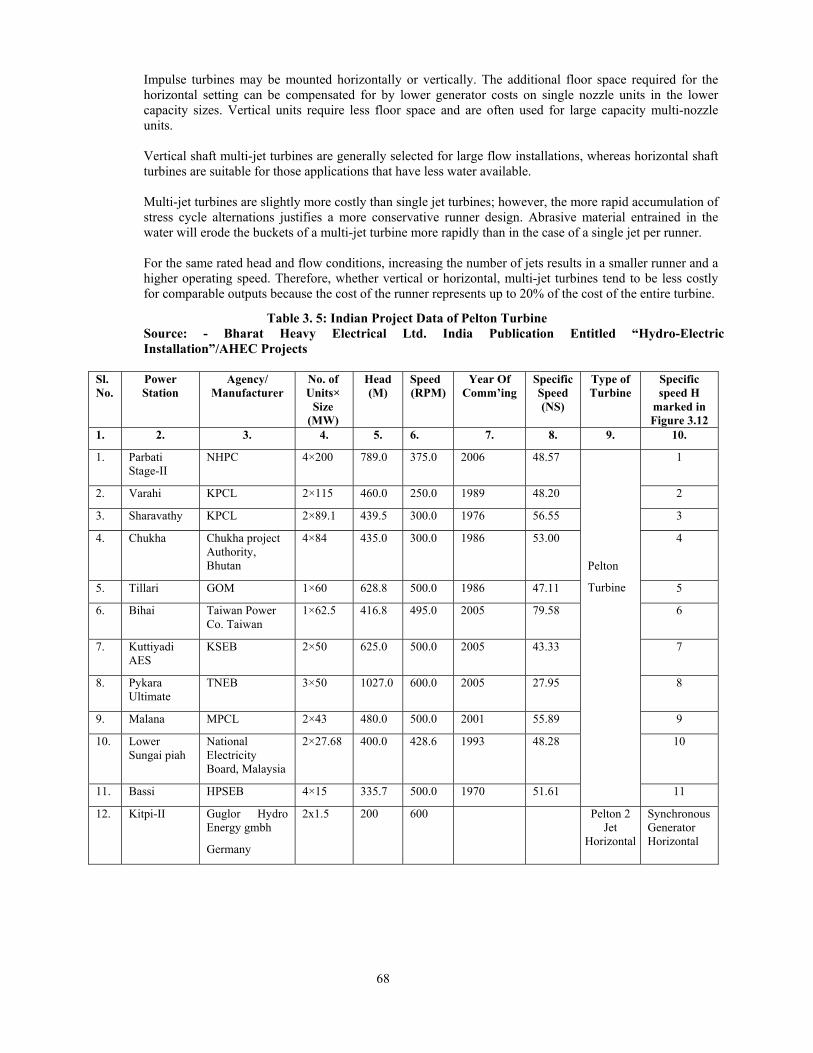
Table 3. 5: Indian Project Data of Pelton Turbine Source: - Bharat Heavy Electrical Ltd. India Publication Entitled “Hydro-Electric Installation”/AHEC Projects
Sl. No.
Power Station
Agency/ Manufacturer
No. of Units×
Size (MW)
Head (M)
Speed (RPM)
Year Of Comm’ing
Specific Speed (NS)
Type of Turbine
Specific speed H
marked in Figure 3.12
1. 2. 3. 4. 5. 6. 7. 8. 9. 10.
1. Parbati Stage-II
NHPC 4×200 789.0 375.0 2006 48.57
Pelton
Turbine
1
2. Varahi KPCL 2×115 460.0 250.0 1989 48.20 2
3. Sharavathy KPCL 2×89.1 439.5 300.0 1976 56.55 3
4. Chukha Chukha project Authority, Bhutan
4×84 435.0 300.0 1986 53.00 4
5. Tillari GOM 1×60 628.8 500.0 1986 47.11 5
6. Bihai Taiwan Power Co. Taiwan
1×62.5 416.8 495.0 2005 79.58 6
7. Kuttiyadi AES
KSEB 2×50 625.0 500.0 2005 43.33 7
8. Pykara Ultimate
TNEB 3×50 1027.0 600.0 2005 27.95 8
9. Malana MPCL 2×43 480.0 500.0 2001 55.89 9
10. Lower Sungai piah
National Electricity Board, Malaysia
2×27.68 400.0 428.6 1993 48.28 10
11. Bassi HPSEB 4×15 335.7 500.0 1970 51.61 11
12. Kitpi-II Guglor Hydro Energy gmbh
Germany
2x1.5 200 600 Pelton 2 Jet
Horizontal
Synchronous Generator Horizontal

69
Figure 3.9: Impulse Turbine for Kitpi Project (2 x 1500 kW) Arunachal Pradesh (Source: - Alternate Hydro energy Centre, IIT, Roorkee)
A deflector is normally used to cut into the jet when rapid power reduction is required such as a complete loss of connected-load. The deflector is mounted close to the runner on the nozzle assembly and is typically provided with its own servomotor. A typical installation is shown in figure 3.9. A list of typical large and small hydro projects with indigenous turbines is shown in table 3.5.

70
Turgo Impulse Turbines: Another type of impulse turbine is the Turgo impulse. This turbine is higher in specific speed than the typical impulse turbine. Eric Crewdson originally patented this turbine in 1920. The difference between a Pelton unit and a Turgo is that, on a Turgo unit, the jet eneters one side of the runner and exits the other side. The Turgo unit operates at a higher specific speed, which means for the same runner diameter as a Pelton runner, the rotational speed can be higher. The application head range for a Turgo unit is 15 meters to 300 meters. Turgo units have been used for application up to 7,500 kW. Efficiency of a Turgo impulse turbine is about 82 – 84%. Cross Flow Turbine: A cross flow turbine is an impulse type turbine with partial air admission.
Performance characteristics of this turbine are similar to an impulse turbine, and consist of a flat efficiency curve over a wide range of flow and head conditions. The wide range is accomplished by use of a guide vane at the entrance, which directs the flow to a limited portion of the runner depending on the flow. This operation is similar to operation of multi-jet impulse turbine.
Peak efficiency of the cross flow turbine is less than that of other turbine types previously discussed. Guaranteed maximum efficiency seldom exceeds 80%. Efficiency of indigenous available turbines is about 60-65%.
The largest size runner of cross flow is about 1.2 meter in diameter. This limits unit capacity but multi-unit installations can be used. Allowable heads range from 2 meter to 180 meter.
Cross flow turbines are sometimes equipped with a conical draft tube creating a pressure below atmosphere in the turbine chamber. Therefore the difference between the turbine centerline elevation and the tail water is not lost to Cross-flow turbines as is the case for an impulse turbine. Air is admitted into the chamber through an adjustable air inlet valve used to control the pressure.
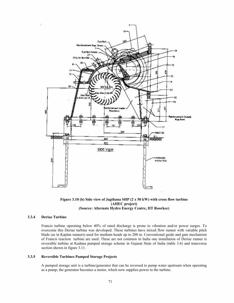
Cross flow turbines are free from cavitation, but are susceptible to wear when excessive silt or sand particles are in the water. Runners are self-cleaning and, in general, maintenance is less complex than for the other types of turbines. Cross section and Side view of cross flow turbine of Jagthana SHP is at figure 3.10 (a) & figure 3.10 (b).
Figure 3.10 (a) Cross section view of Jagthana Cross Flow SHP (2 x 50 kW) – AHEC Project (Source: Alternate Hydro Energy Centre, IIT Roorkee)
71
Figure 3.10 (b) Side view of Jagthana SHP (2 x 50 kW) with cross flow turbine (AHEC project)
(Source: Alternate Hydro Energy Centre, IIT Roorkee)
3.3.4 Deriaz Turbine
Francis turbine operating below 40% of rated discharge is prone to vibration and/or power surges. To overcome this Deriaz turbine was developed. These turbines have mixed flow runner with variable pitch blade (as in Kaplan runners) used for medium heads up to 200 m. Conventional guide and gate mechanism of Francis reaction turbine are used. These are not common in India one installation of Deriaz runner is reversible turbine at Kadana pumped storage scheme in Gujarat State of India (table 3.6) and transverse section shown in figure 3.11.
3.3.5 Reversible Turbines Pumped Storage Projects
A pumped storage unit is a turbine/generator that can be reversed to pump water upstream when operating as a pump; the generator becomes a motor, which now supplies power to the turbine.

72
Starting the unit in the pumping mode requires a means of accelerating the generator/motor in the pump direction. Regardless of how it is done, the motor is started with gates closed and tailrace water depressed. Once the unit is at full speed and on line, the depressing air is vented and the pump is primed. The gates are then opened and pumping begins. Six of the most common methods of starting are as follows:
a) Full voltage, Across – the – line starting b) Reduce voltage, Across – the – line starting c) Synchronous starting semi- synchronous starting d) Motor starting e) Static starting
Figure 3.11: Kadana Pumped Storage reversible Units 4 x 60 MW (Deriaz Units) (Source: CBI&P Publication No. 288)
A typical transverse section of Kadana pumped storage scheme in Gujarat State with reversible turbines with Deriaz runners is shown in figure 3.11.
Water Turbines a) Numbers 4 b) Type reversible pump/turbine, diagonal,
8 DR 35 with adjustable blade c) Net head Turbine pumping Maximum 48.2 m 51.0 m Minimum 30.77 m 35.0 m Rated 43.5 m 47.0 m d) Rated output of each unit 60 MW e) Normal speed 142.86 rpm f) Runaway speed 283 rpm
Typical starting time is less than ten minutes. List of notable pumped storage unit with reversible turbine and their types is given in table 3.6

73
Table 3.6: Indian Project Data of Reversible Pump/Turbine Source: - Bharat Heavy Electrical Ltd. India Publication Entitled
“Hydro-Electric Installation”
S. No.
Power Station Type of turbine
No. of Unit Size (MW)
Head (m) Turbine/pump
Speed (RPM)
Yearly commissionin
g 1. Sardar Sarovar Francis 2 x 200/220 116.6/114.0 136.4 2006 2. Srisailam LBPH Francis 2 x 150/170 82.8/107.1 136.4 2003 3. Ghatghar Francis 1 x 125/142 410/425 500.0 2004 4. Kadamparai Francis 4 x 100/200 341.0/381.0 500.0 1987 5. Nagarjunsagar Francis 3 x 100.8/106 93.0/97.0 157.8 1982 6. Kadana Deriaz 4 x 60/66.5 43.5/47.0 142.8 1990
3.4 SELECTION OF HYDRAULIC TURBINE- GENERAL CONSIDERATION 3.4.1 General
Various types of turbines have already been explained in Para 3.3. Selection of hydraulic turbine up to 5 MW units size (including micro hydros) is generally based on IEC: 1116. Selection of turbines above 5 MW or those in overlapping range is carried out by a more detailed procedure. In any case standard turbines are generally used up to 5 MW unit size. Hydraulic turbine above 5 MW unit size are generally tailor made and selection criteria is more specific. Head, discharge and efficiency play most important role in selection of turbine.
Specification requires that the manufacturer be responsible for the mechanical design and hydraulic efficiency of the turbine. Objective of these guidelines is to prepare designs and specification so as to obtain a turbine that result in the most economical combination of turbine, related water passages, and structures. Competitive bidding for the least expensive turbine that will meet specification requirements is required. In evaluating the efficiency of a proposed turbine, the performance is estimated on the basis of experience rather than theoretical turbine design. The peak efficiency point of a Reaction turbine is established at 90% of the rated capacity of the turbine. In turn, the peak efficiency at 65% of rated head will drop to near 75%.
To develop a given power at a specified head for the lowest possible first cost, the turbine and generator unit should have the highest speed practicable. However, the speed may be limited by mechanical design, cavitation tendency, vibration, drop in peak efficiency, or loss of overall efficiency because the best efficiency range of the power efficiency curve is narrowed. The greater speed also reduces the head range under which the turbine will satisfactory operate.
The selection of speed and setting (from cavitation considerations) described in these guidelines is satisfactory for conditions normally found at most sites and will usually result in a balance of factors that will produce power at the least cost.
Impulse turbines have application in high head hydropower installations. Application of impulse turbine in low head range is limited to very small size units.
3.4.2 Head: Selection of rated and design head for reaction turbine requires special attention. Definition of these
heads is given in Para 3.2.2. Permissible range of head for reaction turbines for optimum efficiency and cavitation characteristics based on experience data is given in table 3.1.
It is important that these operating head ranges are not exceeded. A typical example is of 120 MW Bhakra Right Bank on River Satluj in Punjab/Himachal State Border. Where vertical Francis Turbines were installed. In order to utilize additional water available due to construction of Beas Satluj Link Project subsequent to construction of Bhakra Dam and injection of additional water upstream of Bhakra Dam.

74
Rated, maximum and minimum head were specified as follows in table 3.4.1 in order to obtain more power in low head period.
Table 3.7 Bhakra Right Bank 1966
Maximum net head 158.5 m (520 ft.) Minimum net head 79.86 m (262 ft.) Rated head 121.92 m (400 ft.) Rated output at rated head 150,000 BHP (150,000 – 170,000 BHP) at 90% gate Rated generator 120,000 Kw 120,000 kW at 0.9 pf Speed 187.5 rpm
The turbine rating is given at rated head. Selection of head for 120 MW Bhakra Right Bank power plant (commissioned in 1966) is an example of poor selection as later reviewed. The turbine were rated 170,000 BHP at not more than 90% full gate opening under an effective head (rated head) of 121.92 m (400 ft.) The point of best efficiency of turbine (design head) was also specified as 121.92 m (400 ft.) Net head variation was specified 158.5 m (520 ft.) maximum to 79.86 m (262 ft.) minimum. The turbine was coupled to 120 MW generator. An oversized turbine runner was installed with effective rated/design head at about 355 ft. Part load operation was not possible vibration and surges were noticed. The turbine gave rated output at about 84% gate opening at rated head. Turbines mostly operated at net heads of 400 ft. and above resulting in further maloperation. Generating units were uprated to 132 MW in 1975 for smooth operation by encroaching on safety margins. The units were later on replaced by higher sized properly rated machines at higher rated head. Accordingly determination of rated head, design head and maximum and minimum net head is important. Permissible departure from design head for reaction turbines for optimum efficiency and cavitation characteristics based on experience data is given in table 3.1 and is shown in figure 3.1.
3.4.3 Discharge and Plant Rating
Available discharge and its variation is also important for checking plant rating and capacity limitations for part load operations. Performance curve for various types of reaction turbines for part load operations are discussed in chapter 5. Figures 5.2.1 & 5.2.2 and could be used for preliminary selection of reaction turbines. Exact figures can only be given by turbine manufacturer.
Plant kilowatt rating = 9.804 X (rated discharge in m3/sec.) X (rated head in meters) X (plant efficiency)
1 megawatt = 1000 kW
Plant factor = average plant output/plant capacity
3.4.4 Specific Speed (Ns) – The term specific speed used in classifying types of turbines and characteristics of
turbines within types is generally the basis of selection procedure. This term is specified as the speed in revolutions per minute at which the given turbine would rotate, if reduced homologically in size, so that it would develop one metric horse power at full gate opening under one meter head. Low specific speeds are associated with high heads and high specific speeds are associated with low heads. Moreover, there is a wide range of specific speeds which may be suitable for a given head. Selection of a high specific speed for a given head will result in a smaller turbine and generator, with savings in capital cost. However, the reaction turbine will have to be placed lower, for which the cost may offset the savings. The values of electrical energy, plant factor, interest rate, and period of analysis enter into the selection of an economic specific speed. Commonly used mathematically expression in India for specific speed is power based (English System) is as follows:
Power Based Specific Speed Nsp
Nsp = ( )
( ) 25.1
5.0
HPN

75
Where N = revolutions per Minute
P = power in metric horse power/kW at full gate opening H = rated head in m.
The specific speed value defines the approximate head range application for turbine type and size. Low head units tend to have a high specific speed, and high-head units to have a low specific speed. Ns, kW Units = 0.86 Ns metric horse power unit Flow Based Specific Speed Nq Flow based metric system for specific speed (Nq) used in Europe is given by equitation below. This can be derived from Nq as P α QH
Nq = 75.0
5.0
HNQ
Where Nq = Specific Speed N = Speed in rpm Q = Flow in cubic meters/second
H = Net Head in meters
The net head available to the turbine and unit size dictates the selection of type of turbine suitable for use at a particular site. The term specific speed is generally used in classifying types of turbines and characteristics within type as shown in figure 3.12. This figure is based on ASME guide to design of hydropower mechanical design 1996 and modified by Indian Projects data given from table 3.2 to table 3.6. Relationship between head and specific speed for preliminary selection of turbine types as per Indian Standard 12837 is given in figure 3.13. Overlapping range of the three types of turbine is shown in figure 3.12.
Figure 3.12 Ns versus Head.- This figure shows the various turbine type as a function of specific speed (Ns) and head. This figure should be used a guideline, as there is overlap between the various turbine types with respect to their operating ranges. Note: Details of turbine marked on the chart refer (Table 3.2 – Francis Turbine; Table 3.3 – Kaplan/Propeller Turbine and Table 3.5 for Pelton Turbine).
Ns = ( ) 4/5
dHPN
Ns (Specific Speed) Based on Optimum Point
N = Speed (rev./min.) P = Turbine full gate capacity in HP (metric) H = Head (m)

76
Figure 3.13 Relationship between Head and Specific Speed (Source – IS: 12837)

77
3.5 SELECTION CRITERIA OF HYDRO TURBINE ABOVE 5 MW UNIT SIZE
Factors Influencing Selection of a Turbine and Specific Speed are as follows:
a) Head available to the turbine b) Turbine efficiency c) Speed in rpm d) Cavitataion and plant setting e) Part load operation f) Runaway speed g) Machine size – runner diameter
Selection of turbines for a particular site is determined by trial and error process and in consultation with manufacturers for optimum determination of the type, size, setting and efficiency.
Criteria for selection of hydro turbine based on specific speed as per Indian standard IS: 12837 is given in table 3.8.
Table: 3.8
Type of machine
Head variation % of rated head
Load variation % of rated output
Specific speed (m-mhp)
Peak efficiency in %
Pelton 120 to 80 50 to 100 15 to 065 90 Francis 125 to 65 40 to 100 60 to 400 93 Deriaz 125 to 65 50 to 100 200 to 400 92 Kaplan 125 to 65 40 to 100 300 to 800 92 Propeller 110 to 90 90 to 100 300 to 800 92 Bulb 125 to 65 40 to 100 600 to 1200 92
Prior to issue of Indian standards, Engineering Mono graph No. 20 (USBR) was mostly used for selection of reaction turbines. 3.5.1 Head, Output and Type of Turbine
Determine Type of turbine from figure 3.12; figure 3.13 and table 3.8 for the design head determined from site data. In case of overlapping ranges turbine types applicable may be noted and approximate range of Specific speed applicable to the turbine may be determined from the figures and table mentioned above for detailed economic analysis. This analysis is based on speed, efficiency, part load operation, setting and size of a turbine. USBR monograph recommends that except for unusual circumstances, the trial specific speed for reaction turbines may be based on specific speed near about (2334/ dh metric). This figure in earlier edition of the monograph was much lower. This indicates trend for higher speed reaction turbine. Present trend is to select higher trial specific speed (see chapter 14). Head Variations: Performance of the turbine is ideal at design head. Turbine efficiency falls at head higher and lower than the design head. Normal range of head variations for various type of turbines is given in table 3.8.
3.5.2 Efficiency
Relative efficiency of different type of units as per IS: 12800 is shown in figure 3.8.
Relative Francis versus full Kaplan (Variable blades and wicket gates) efficiency curve is shown in figure 3.15.

78
3. Efficiency of indigenous cross flow turbine is about 60 - 70%. 4. Peak efficiency at design head and rated output is about 2-5% higher.
Figure 3.14 Turbine Efficiency Curves (Source IS: 12800)
Figure 3.15: Francis Versus Kaplan Relative Efficiency. Kaplan turbine has much better part load efficiency than propeller or Francis turbines (Typical)

79
3.5.3 Load variations
Turbine efficiency varies with load. Necessity of operating turbine at part loads influences choice of turbines in the overlapping head ranges. Minimum load up to which the turbine may be operated without undue cavitation and vibration is dictated by type of turbine and given in table 3.8.
3.5.4 Runner Size
Runner size determines turbine size, the civil engineering cost and hence is important for selection of turbines. Actual runner size is determined by the manufacturer in accordance with model tests data. For preliminary selection of turbine and layout purposes following formula can be used as per IS: 12800. Francis Turbine:
( ) 3/20211.0 ss n=θ
Runner diameter, D = ( )n
H rs2/16.84 θ
Where sθ is the velocity ratio at discharge diameter of runner. Propeller Turbine:
( ) 3/20233.0 ss n=θ
Runner diameter, D = ( )n
H rs2/16.84 θ
Impulse Turbine:
ss nDd 0019.0=θ
Where d = diameter of jet
D = ( )n
H rs2/16.84 θ
Practical values of 1.004.0 toDd=
Normal diameter ratio is = 0.0555
3.5.5 Transport Consideration In case of large unit rating machines, this criteria plays important role in selecting of turbine size. Normally runner is one of the costliest and most critical parts which should be preferably handled in one piece. Reliability of assembled large Kaplan size runner is much less on account of possibility of removing runner blades easily as they are fixed by bolts and keys. In case of Francis turbines, necessity of limiting runner size during transport, requiring manufacture of runner in two pieces increases cost of the turbine by about 10%. Pelton turbine runner as a rule is transported in one piece.
Bhakra Right Bank power unit size was fixed on the basis of maximum runner size cast in one piece that could be manufacture and transported to site.

80
3.5.6 Turbine Setting and Excavation Requirement Setting of reaction turbine with reference to minimum tail water level is dictated by requirement from cavitational considerations. Further in view of bent draft tube, excavation up to bottommost point of knee that is much deeper than runner centre line is required. In general cavitation co-efficient for Francis turbines is much less than that for Kaplan turbine necessitating relatively lesser submergence and excavation for Francis turbine. Pelton turbines are installed above maximum tail water level, thus requiring minimum excavation cost.
Highest speed practicable at specified head is required for lowest possible cost. In addition greater speed requires the reaction turbine (Francis and Propeller/Kaplan) to be placed lower with respect to the tailrace water to avoid cavitation. This generally increases excavation and structural costs.
Cavitation results from sub-atmospheric pressure at places on runner and runner chamber. To minimize this problem the turbine runner is set at depths below the minimum tail water to obtain a countering pressure. The appropriate value of the depth of setting for runner of different specific speed is computed using a characteristic ‘cavitation coefficient’ for the particular specific speed, as follows:
Z = (Ha - Hv) - σH
Where,
Z = Depth of centre line of runner below minimum level of tail water Ha = Atmospheric pressure in meter (m) water column at plant elevation Hv = Vapour pressure in meters at plant location temperature H = head on turbine, meters σ = Plant sigma or cavitation coefficient for the turbine specific speed
The value for σ for selection purposes may be found from the expression which is as follows (IS: 12800):
σ = ( )50327
64.1sn
The value of σ can also be taken from the curves relating ns and σ shown in USBR Enguineering Monograph No. 20. The value of σ for Francis turbine is lower than those for Propeller or Kaplan turbines. The setting level for the latter is consequently lower than for Francis turbine. Many low ns Francis turbines will yield setting levels above minimum tail water level and same may be the case with Kaplan/ Propeller turbines of very low heads. Pelton turbines are set above the maximum tailrace water level.
Atmospheric pressure and vapour pressure (meter) is given in table 3.9 and setting of the turbine is based on the cavitation coefficient.
Table 3.9
Atmospheric PressureAltitude meters
Ha mm of Hg
Ha m of H2O
0 760.00 10.351 500 715.99 9.751 1000 674.07 9.180 1500 634.16 8.637 2000 596.18 8.120 2500 560.07 7.628 3000 525.75 7.160 3500 493.15 6.716 4000 462.21 6.295
Water Properties Temp
0F Hv
Meter Temp
0C 40 0.089 5 50 0.125 10 60 0.174 15 70 0.239 20 80 0.324 25

81
Ha = Atmospheric pressure for altitude (m) Hv = Vapour Pressure of water, use highest expected temperature, (m) Hb = Ha – Hv , Atmospheric pressure minus vapor pressure , (m)
3.5.7 Other Considerations
Other considerations for selection of the type of large turbine are as follows:
i) Performance of turbine is ideal, at design head. Fall of efficiency in case of pelton, Kaplan and Bulb is much less in comparison to Francis and propeller types. Therefore in overlapping head ranges selection of type of turbine is affected by head variation existing at site.
ii) Turbine efficiency varies with load. Fall of efficiency at part load for Francis and propeller is much steeper in comparison to that for Kaplan and Pelton turbines, therefore, necessity of operating turbines at part loads for longer time influences choice of turbines in the overlapping head ranges. Thus in the head ranges where both Kaplan and Francis are suitable, requirement of large head and load variation, Kaplan turbine is superior to Francis turbine from considerations of higher power generation on account of better overall efficiency. Similarly, in the overlapping head ranges where both Francis and Petlon could be used, Pelton has advantages over Francis in overall performance level when variation of load is higher.
iii) Highest specific speed of turbine results in higher speed of rotation for generator with consequent reduction in cost of generator. This criteria is very important for resulting type of turbine from cost consideration in the overlapping head ranges (see figure 3.12 & figure 3.13
3.6 SELECTION PROCEDURE FOR TURBINES ABOVE 5 MW UNIT SIZE
The practice for preliminary selecting of large turbines (reaction turbine mostly used) is based on trial and error method and United States Department of the Interior, Bureau of Reclamation, Engineering Monograph no. 20 entitled Selecting Hydraulic Reaction Turbines and in consultation with manufacturer of the equipment.
(i)Trial specific speed ns; Select from figure 3.12 or figure 3.16 trial specific speed. For reaction turbines trial specific speed is
revised from H
2010 to
H2334
as per USBR monograph no. 20. High trial specific speed is recommended
as shown in figure 3.16. See also chapter 14 for modern trends.
(ii)Trial speed N ′ (rev./min.)
N ′= ( )
PHN ds
4/5×
Where, N ′= Trial rotational speed
sN ′= Trial specific speed Hd = Design head P = Turbine full gate capacity at Hd (metric horse power)
(iii) Rotational speed or design speed, n: The rotational synchronous speed nearest the design speed is selected subject to the following considerations:
a. A multiple of four poles is preferred, but standard generators are available in some multiples of two poles.

82
b. If the head is expected to vary less than 10% from design head, the next greater speed may be chosen. A head varying in excess of 10% from design head suggest the next lower speed.
Specific Speed (power based) Figure 3.16: Specific Speed
3.6.1 Examples of Medium and Large Turbine Selection
Some examples of selecting hydraulic turbines especially in the overlapping range are given below: 3.6.1.1 Turbine Selection of Dehar Powerhouse (4 x 165 MW) of Beas Satluj link Project
The Turbines were selected in consultation with Bharat Heavy Eelctricals Ltd. (BHEL), the supplier of equipment.
Basic data for the turbine selection is as follows: Rated head (H) - 341.4 m Rated output (P) - 23000 HP Generator Output - 165000 kW
This falls within the overlapping range of Francis and Pelton turbine range (Figure 3.12).
Ns = ( ) 4/5H
PN
N = ( )
PHN s
4/5
Hea
d (m
)
83
N = ( )
000,2304.341 4/5×sN
N = 3.06 Ns The value of Ns form figure 3.12 lies approximately in following limits for rated head 341.4m
Pelton Turbine – 50 to 100 Francis turbine - 100 to 125
Choosing a six jet pelton turbine (Ns = 20 per jet) and reaction francis turbine with
Ns = H
2010 = 109 (based on USBR monograph no. 20) for trial purpose and comparison is shown in table
3.6.1.
Reaction Turbine
Trial specific speed Nsp = H
2010 =
4.3412010
= 109.2 (based on USBR monograph
No. 20-1954) Trial Speed N’ (rpm)
N’ = ( )pHN s
4/5× =
( )23000
4.341109 4/5× =
6.4795.1467109×
= 333 RPM
Nearest synchronous speed for even no. of pairs of pole (20) = 150 RPM (6 jet pelton)
(10) = 300 RPM (reaction turbine) (8) = 375 RPM (reaction turbine)
Table 3.10 S. No. Type of Turbine Ns
n (rpm) = 3.06 Ns
Synch. Speed
1. 6 jet pelton 20 per jet 149 150 2.
a) Francis b)
100 120
306 367
300 375
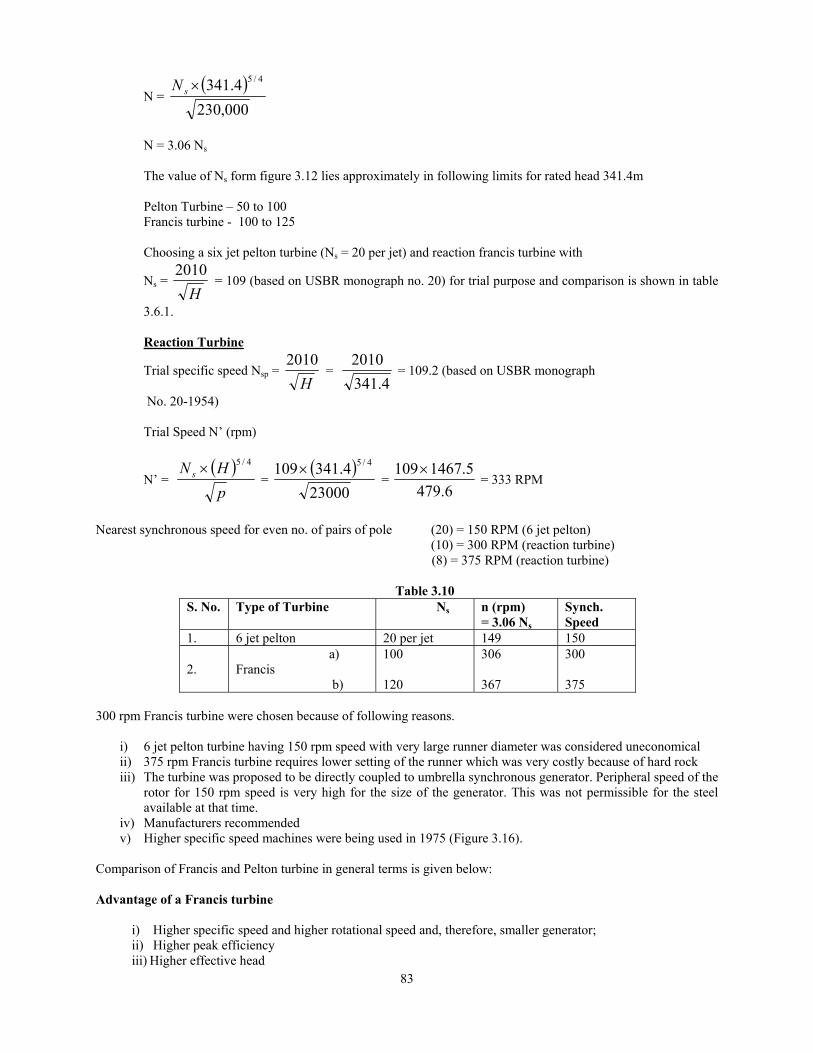
300 rpm Francis turbine were chosen because of following reasons.
i) 6 jet pelton turbine having 150 rpm speed with very large runner diameter was considered uneconomical ii) 375 rpm Francis turbine requires lower setting of the runner which was very costly because of hard rock iii) The turbine was proposed to be directly coupled to umbrella synchronous generator. Peripheral speed of the
rotor for 150 rpm speed is very high for the size of the generator. This was not permissible for the steel available at that time.
iv) Manufacturers recommended v) Higher specific speed machines were being used in 1975 (Figure 3.16).
Comparison of Francis and Pelton turbine in general terms is given below: Advantage of a Francis turbine
i) Higher specific speed and higher rotational speed and, therefore, smaller generator; ii) Higher peak efficiency iii) Higher effective head

84
Advantages of a Pelton Turbine
i) Excavation cost will be less ii) Often better for applications with erosive water – easier to maintain iii) Better part – load efficiency – very flat efficiency curve for approximately 25% to 100 % load, particularly
with multi jet units. iv) Less sensitive to changes in head v) Wider operating range – particularly with multi jet units. vi) Rapid operation of deflectors minimizes water hammer and may, therefore, eliminate the need for a surge
tank. A Francis turbine needs longer closing time, resulting in longer and higher over speeds. vii) It is simple with fewer moving parts and may have lower maintenance costs.
Francis turbines 300 RPM directly coupled to synchronous generators were chosen in consultation with the manufacturers. 3.6.1.2 Example of Turbine Selection of 20 MW Unit Size (Matnar Project, Chhatisgarh) 1.Turbine Selection Basic Data
i) Rated design head : 57.75 m ii) Rated Turbine Discharge : 41.57 cumecs iii) Total discharge : 124.72 cumecs iv) Maximum tailrace level : 468.25 m v) Rated output at rated head : 20 MW and rated discharge (at generator terminals)
As per figure 3.12 turbine falls within the range of Francis turbine. Net design head (hd) = 57.75 m Turbine full gate capacity at rated load (10% overload on generator 96% generator efficiency and 5% margin. Generator rated output = 20,000 kW (10% overload capacity) = 22,000 kW
Turbine rated output required = 86.096.0
05.110.120000×
××= 27980 MHP
Trial Specific Speed ( )sn′ = dh
2334 (metric)
= 75.57
2334=307 (Graph 3.4.1 shows ns ~ 200-300)
Trial Rotational Speed ( )n′ = d
ds
Phn 4/5)(' ×
(based on USBR monograph No. 20-1974)
= 27980
)75.57(307 4/5×= 292.2 ≅ 300 or 250
Design Speed Head is expected to vary less than 10% from design head and the next greater speed may be chosen. Accordingly 10 pole (5 pairs pole) generator with design speed of 300 rpm is optimum choice.

85
Design Specific Speed (ns)
ns = ( ) 4/5
d
d
h
Pn
= ( ) 4/575.57
27980300 = 315.21
= 315 Discharge Diameter (D) (as per 3.5.4)
Velocity ratio (φ) = 0.0211 ( ) 3/2sn
= 0.0211 ( ) 3/2315 = 0.9768
D = n
hd×Φ×6.84
= 300
37.819768.06.84 ××
= 2.09 m Manufacturer M/s BHEL intimated following parameters for the turbine of Matnar project Design head = 57.75 m Turbine output = 20000 kW (without 10% overloads) Rated speed = 300 rpm Runner dia. = 2.08 m 3.6.1.3 Example of Turbine Selection for Medium size Low Head Schemes (Mukerian & SBC Canal Fall
Projects)
For low head large size units equipment costs are high. Selection Criteria
For a small/medium low head power station, the operating and installation costs are comparatively much higher with respect to large installations. This means that greater consideration must be given to the following points:
1. The Civil Engineering work needs to be kept to a minimum. 2. The site erection of the units has to be kept to a minimum. 3. The power station must be automatically controlled to reduce the attendant personnel. 4. The equipment must be simple and robust with easy accessibility to essential parts for maintenance. 5. Indian experience & Indigenous availability
For low heads, vertical Kaplan/ Bulb turbine is suitable for these requirements. The main advantage of the bulb unit derives from its hydraulic simple and straight water passage. The consequence of this is a smaller turbine and a reduced civil works cost.
The turbine is smaller because the bulb unit has a higher specific speed and a higher specific output than other types of turbines while maintaining or even improving the efficiencies and cavitation characteristics.
Selection of turbines is discussed with special reference to Mukerian & SBC Canal Projects.

86
Turbine Selection Basic Data
Mukerian SBC Rated/design head 8.23 m/8.23 m 11.20/11.20 m Rated output 2 x 9000 kW 2 x 8000 kW
Power House Dimensions for Vertical Kaplan and Kaplan Bulb Turbine Mukerian SBC Design Head (H) = 8.23 m 11.20 m Rated Power (P) = 2 x 9,000 kW 2 x 8,000 kW
Specific Speed (ns) is related to rotational speed (n): Mukerian SBC ________ n / P n x (9,000)1/2 n x (8,000)1/2 ns = --------------- = ------------ H5/4 (8.23)5/4 (11.20)5/4 n = 0.1477ns 0.229 ns
Runner diameter (D) and speed for possible values of ns for vertical Kaplan based on U.S.B.R. Monograph no. 20 taken as 2334/ H 1 and bulb turbines taken as about 15-25 percent higher is worked out in Table-4.8. Nearest synchronous speed is chosen. The runner diameter and setting is calculated as per U.S.B.R. Design Monograph No. 20 (titled selection of hydraulic turbines). Comparison of the figures for the two types is shown in Table-3.11.
Table – 3.11
Types of Turbine
ns (Trial)
n (rpm) Actual ns Runner Diameter (meter)
Setting above Tail race (meter)
SBC Mukerian SBC Mukerian SBC Mukerian SBC Mukerian SBC
Vertical Kaplan
a) 700 850 166.7 125 730 800 3.210 4.06 - 3.50 b) 700 - 187.5 - 819 - 3.080 - - 5.60
Bulb Turbine
a) 850 1000 187.5 150 819 1020 3.080 3.82 - 8.16 b) 850 - 200 - 873 - 3.015 - - 8.27
*Assuming 1 m as safety margin for vertical Kaplan and 0.5 m for Bulb units. Vertical Kaplan turbines can be coupled directly to 166.7/125 r.p.m. (18/24 pole) generators for SBC/Mukerain and Bulb turbines can be coupled to 187.5/200/136.5 r.p.m. (16/15/22 pole) generators for SBC/Mukerian. Following reputed manufacturers of equipment responded to our enquiries for the generating equipment (turbine and generator) selection for SBC turbine. (1) M/s Bharat Heavy Electricals Ltd. INDIA (2) M/s Fuji Electric JAPAN (3) M/s Sulzer Flovel Hydro Ltd. INDIA (4) M/s Jyoti Ltd. INDIA
Table – 3.12 Sl. No Manufacturer Type of Offered turbine Synchronous Speed Runner Diameter Draft Head 1. Bharat Heavy
Electricals Ltd. Horizontal Bulb 7500 kW Output at 10.9 m head
150 r.p.m. --------
2. M/s Fuji Horizontal Bulb 7500 kW Output at 10.9 m head
200 r.p.m. 3150 mm - 8 m
3. M/s Sulzer Vertical Shaft Kaplan 7980 kW Coupling to 7500 kW Gen. at 10.9 m head
166.7 r.p.m. 3400 mm

87
M/s Jyoti Ltd. offered 3 x 5000 kW units tubular type of Kaplan units. They further indicated capability of making Kaplan units up to 10000 kW unit size. For the purpose of comparison of similar unit size data supplied by the manufacturers for 7500 kW unit size (Vertical Kaplan or Bulb type) are given in table 3.12. Experience with Bulb Turbines 1. Indigenous Experience - A large number of Bulb units have been installed in India and have been in
satisfactory operation for quite some time. List of some of these installations is given in Table 3.13. Table 3.13: Some recent Bulb Turbine Installations in India
S. No.
Developer Location Turbine size (kW)
Head/Speed (m/rpm)
Generator Rema-rks
1. Bihar State Hydro-Electric Power Corporation
Eastern Gandak Canal i. 5155 ii. 5155 iii. 5155
7.1 / 107 5.3 / 107 4.97 / 107
5670 kVA, 6.6 kV 50 Hz each
3 Sets
2. Tamil Nadu State Electricity Board
Cauvery River Mettur Dam Power House I Power House II Power House III Power House IV
i. 17,200 ii. 15,600 iii. 4,400
9.0 / 75 6.5 / 75 3.0 / 75
18,333 kVA, 6.6 kV, 50 Hz
Total 8 Sets
3. Haryana Sate Electricity Board
Western Yamuna Hydro electric Project Power House I Power House II Power House III Power House IV
i. 9,350 ii. 7,310
12.8 / 1875 11.5 / 1875
10440 kVA, 6.6 KV, 50 Hz each
Total 8 Sets
4. Murudeshwar Power Corporation Ltd., Karnataka
Narayanpur Left Branch Canal
4500 kW
7 m/111 rpm
6000 kVA
Two sets
(2) More than 100 bulb units of unit output more than 5 MW, designed and manufactured by M/s Neyperic are
Operating satisfactorily. Largest unit size is 53 MW and cost reduction recommended is reproduced below (Refer proceedings of water Power International Conference, 1985 (pp 749 - 755)).
The specific speed increase reaches at least 20%. This means that for a given head and output the use of a Bulb
unit allows a turbine diameter about 10% smaller than with a conventional turbine. Moreover, the main advantage of the Bulb turbine is the reduction in civil works. When compared to a Vertical
Kaplan unit, the inlet width is at least 50% smaller, all these together bringing to a total gain of about 25 to 35% of the civil costs. When compared to a tubular unit, the smaller runner diameter of the bulb unit and its simplicity in design and installation result in an overall reduction in the cost of civil works.
(3) A comparison of vertical Kaplan and Kaplan Bulb units for Idaho falls in USA was made by International
Engineering Co. of USA for Department of Energy. Unit size is 7.2 MW and head 5.8 estimated saving in cost was as follows:
Estimated saving in equipment cost = 10% Reduction in cost of Civil Engg. Works = 50% Bulb units supplied by M/s Voest Alpine are working satisfactorily.
Conclusions and Recommendations Bulb Turbines were recommended for both the powerhouse.
88
3.7 SELECTION OF SMALL HYDRO TURBINE UP TO 5 MW UNIT SIZE Factor Affecting Selection of Turbines are as follows: a) Type of scheme b) Use of standard turbines c) Turbine Efficiency d) Turbine performance e) Runner diameter
3.7.1 Type of Scheme 3.7.1.1 High Head Scheme
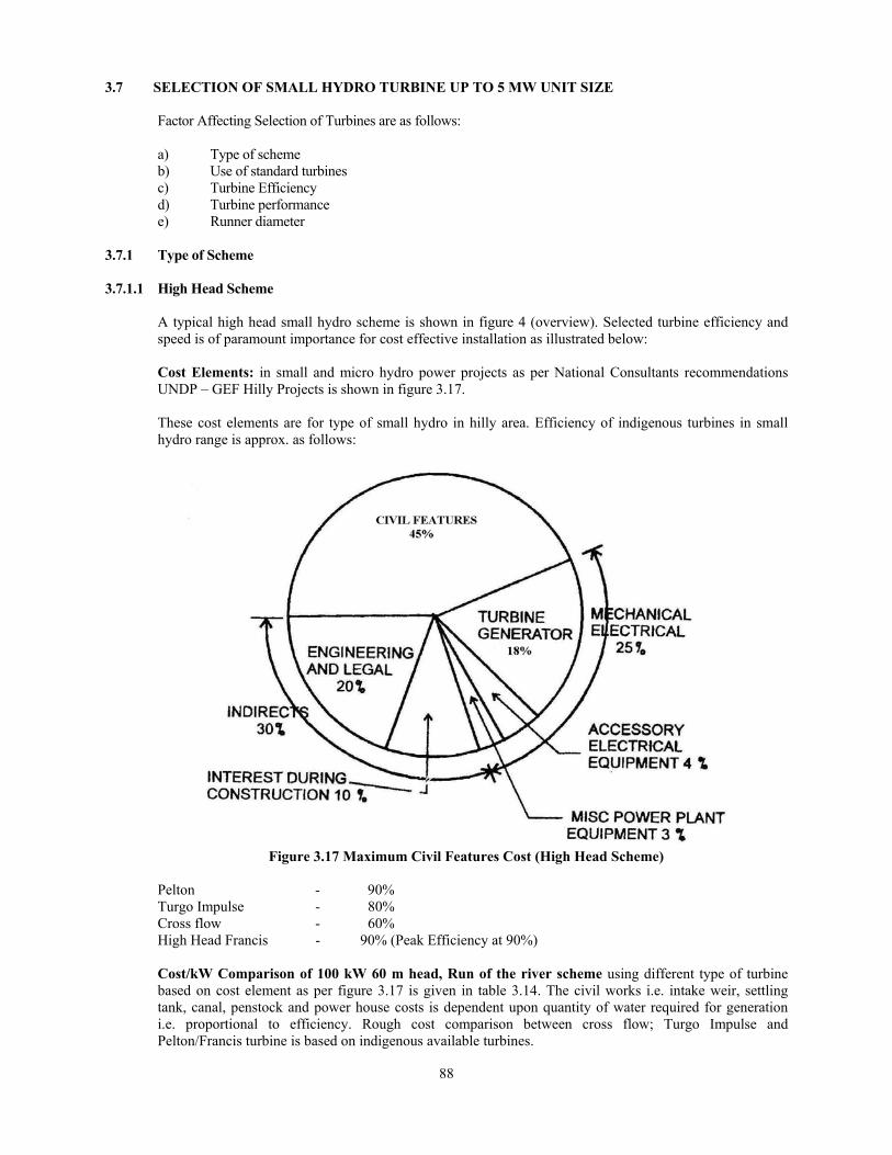
A typical high head small hydro scheme is shown in figure 4 (overview). Selected turbine efficiency and speed is of paramount importance for cost effective installation as illustrated below:
Cost Elements: in small and micro hydro power projects as per National Consultants recommendations
UNDP – GEF Hilly Projects is shown in figure 3.17.
These cost elements are for type of small hydro in hilly area. Efficiency of indigenous turbines in small hydro range is approx. as follows:
Figure 3.17 Maximum Civil Features Cost (High Head Scheme)
Pelton - 90% Turgo Impulse - 80% Cross flow - 60% High Head Francis - 90% (Peak Efficiency at 90%) Cost/kW Comparison of 100 kW 60 m head, Run of the river scheme using different type of turbine based on cost element as per figure 3.17 is given in table 3.14. The civil works i.e. intake weir, settling tank, canal, penstock and power house costs is dependent upon quantity of water required for generation i.e. proportional to efficiency. Rough cost comparison between cross flow; Turgo Impulse and Pelton/Francis turbine is based on indigenous available turbines.

89
Table 3.14
Item Cross flow Turgo Impulse Francis Remarks
Civil works 45% (For Francis turbine)
35100 29700 27000
Electro-mechanical i) Turbine ii) Generator and other equipment
3940 11220
4320 10200
4800 10200
1000/1500 rpm generator for Francis and turgo impulse and 750 rpm gen. For cross flow
Direct cost 50260 44220 42000 Engineering and Indirect cost 21540 18951 18000 Total cost/kW 71800 63172 60000 Francis turbines costs although higher by 20% reduce cost/kW by 20%.
3.7.1.2 Low Head Scheme Cost element in a low head project such as in canal fall projects is shown in figure 3.18 Accordingly equipment cost predominate. Cost of generators is reduced by providing speed increasing gears and accordingly selection of turbine is important for cost affective installation. Accordingly only high specific speed (Axial flow) is possible. Selection procedure is therefore is to select type and configuration of axial flow turbine as clarified in example. Most of the canal falls in the country are below 4 – 5 meter head. Canal schemes in the range lower that 3 meters are designed as ultra low head schemes. Ultra low head scheme are discussed in chapter 13.
Figure 3.18 – Minimum Civil Feature (Low Head Scheme)
3.7.2 Use of Standard Turbine
Cost constraints require use of turbines for which model test data is available. The capacity to be installed could be adjusted as per this data. Typical/Standard turbines available for discharge and head in the country as per data given by some manufacturers (table 3.15) is based on AHEC/MNRE/SHP Standards/E & M Works entitled “Guidelines for Selection of Turbine and Governing System for Hydroelectric Projects” and listed below for guidance. These lists provide following information for the turbine. Rated head; discharge; unit size and runner diameter and configuration. Range of head and discharge not available in the list may be asked from the manufacturer. Runner diameter may be used for preliminary layout of the turbine as per IS 12800 part (3) for economic evaluation.

90
Table 3.15
Standard Turbine by some of the manufacturers in India 3.7.2-A1 BHEL – Standard Tubular Turbines3.7.2-A2 BHEL – Standard Kaplan Turbine3.7.2-A3 BHEL – Standard Francis Turbine (Horizontal Shaft)3.7.2-A4 BHEL – Standard Pelton Turbine (Single Jet – Horizontal Shaft)3.7.2-B1 Flovel – Standard Tubular Turbines – Semi Kaplan3.7.2-B2 Flovel – Standard Tubular Turbines – Full Kaplan3.7.2-B3 Flovel – Standard Pit Type Francis Turbine3.7.2-B4 Flovel – Standard Francis Turbine (Spiral Casing Type)3.7.2-C1 Jyoti – Standard Tubular Turbines3.7.2-C2 Jyoti – Standard Francis Turbines3.7.2-C3 Jyoti – Standard Pelton Turbines3.7.2-C4 Jyoti – Standard Turgo Impulse Turbine3.7.2-D1 HPP – Standard Vertical Kaplan Turbines
Table 3.16A1: BHEL – Standard Tubular Turbines
Runner Dia. (mm)
1200 1500 1800 2000 2200 2500
Head (m) Unit Output Pt (kW) and Discharge Q m3/sec. Pt 75 to 150 150 to 225 225 to 325 325 to 400 400 to 500 500 to 625 3.0 Q 3.18 to 6.36 6.36 to 9.54 9.54 to 13.78 13.78 to 16.96 16.96 to 21.20 21.20 to 26.50 Pt 120 to 250 250 to 375 375 to 525 525 to 650 650 to 825 825 to 1050 4.0 Q 3.82 to 7.95 7.95 to 11.92 11.92 to 16.69 16.69 to 20.67 20.67 to 26.23 26.23 to 33.38 Pt 175 to 335 335 to 525 525 to 750 750 to 925 925 to 1125 1125 to 1450 5.0 Q 4.45 to 8.52 8.52 to 13.35 13.35 to 19.08 19.08 to 23.53 23.53 to 28.62 28.62 to 36.88 Pt 225 to 425 425 to 650 650 to 950 950 to 1175 1175 to 1450 1450 to 1875 6.0 Q 4.77 to 9.00 9.00 to 13.78 13.78 to 20.14 20.14 to 24.91 24.91 to 30.73 30.73 to 39.74 Pt 280 to 525 525 to 800 800 to 1175 1175 to 1450 1450 to 1775 1775 to 2300 7.0 Q 5.09 to 9.54 9.54 to 14.53 14.53 to 21.35 21.35 to 26.34 26.34 to 32.25 32.25 to 41.79 Pt 310 to 525 525 to 825 825 to 1200 1200 to 1450 1450 to 1800 1800 to 2300 8.0 Q 4.93 to 8.35 8.35 to 13.12 13.12 to 19.08 19.08 to 23.05 23.05 to 28.62 28.62 to 36.56 Pt 370 to 625 625 to 1000 1000 to 1450 1450 to 1775 1775 to 2150 – 9.0 Q 5.23 to 8.83 8.83 to 14.13 14.13 to 20.49 20.49 to 25.08 25.08 to 30.38 – Pt 425 to 740 740 to 1175 1175 to 1675 1675 to 2050 – – 10.0 Q 5.41 to 9.41 9.41 to 14.94 14.94 to 21.30 21.30 to 26.07 – – Pt 565 to 850 850 to 1350 1350 to 1950 1950 to 2400 – – 12.0 Q 5.99 to 9.01 9.01 to 14.31 14.31 to 20.67 20.67 to 25.44 – – Pt 675 to 1100 1100 to 1700 1700 to 2475 – – – 14.0 Q 6.13 to 9.99 9.99 to 15.44 15.44 to 22.48 – – – Pt 800 to 1250 1250 to 2000 – – – – 16.0 Q 6.36 to 9.94 9.94 to 15.90 – – – –
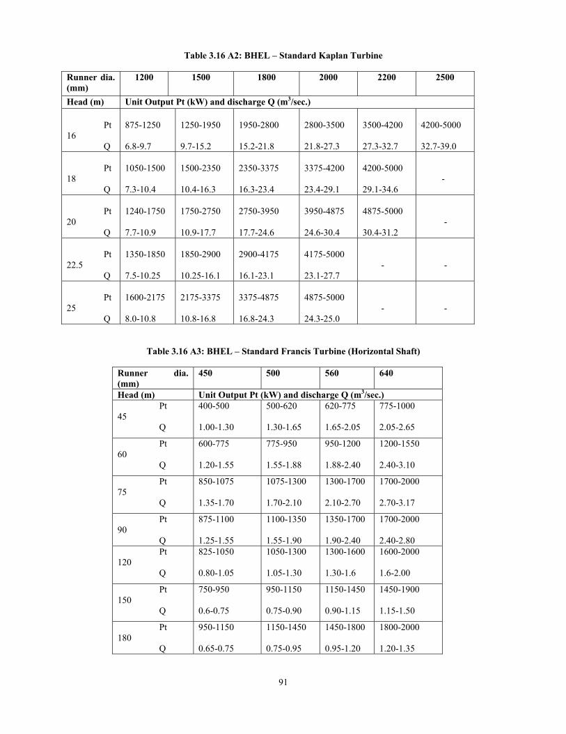
91
Table 3.16 A2: BHEL – Standard Kaplan Turbine Runner dia. (mm)
1200 1500 1800 2000 2200 2500
Head (m) Unit Output Pt (kW) and discharge Q (m3/sec.) Pt 16 Q
875-1250 6.8-9.7
1250-1950 9.7-15.2
1950-2800 15.2-21.8
2800-3500 21.8-27.3
3500-4200 27.3-32.7
4200-5000 32.7-39.0
Pt 18 Q
1050-1500 7.3-10.4
1500-2350 10.4-16.3
2350-3375 16.3-23.4
3375-4200 23.4-29.1
4200-5000 29.1-34.6
-
Pt 20 Q
1240-1750 7.7-10.9
1750-2750 10.9-17.7
2750-3950 17.7-24.6
3950-4875 24.6-30.4
4875-5000 30.4-31.2
-
Pt 22.5 Q
1350-1850 7.5-10.25
1850-2900 10.25-16.1
2900-4175 16.1-23.1
4175-5000 23.1-27.7
-
-
Pt 25 Q
1600-2175 8.0-10.8
2175-3375 10.8-16.8
3375-4875 16.8-24.3
4875-5000 24.3-25.0
-
-
Table 3.16 A3: BHEL – Standard Francis Turbine (Horizontal Shaft)
Runner dia. (mm)
450 500 560 640
Head (m) Unit Output Pt (kW) and discharge Q (m3/sec.) Pt 45 Q
400-500 1.00-1.30
500-620 1.30-1.65
620-775 1.65-2.05
775-1000 2.05-2.65
Pt 60 Q
600-775 1.20-1.55
775-950 1.55-1.88
950-1200 1.88-2.40
1200-1550 2.40-3.10
Pt 75 Q
850-1075 1.35-1.70
1075-1300 1.70-2.10
1300-1700 2.10-2.70
1700-2000 2.70-3.17
Pt 90 Q
875-1100 1.25-1.55
1100-1350 1.55-1.90
1350-1700 1.90-2.40
1700-2000 2.40-2.80
Pt 120 Q
825-1050 0.80-1.05
1050-1300 1.05-1.30
1300-1600 1.30-1.6
1600-2000 1.6-2.00
Pt 150 Q
750-950 0.6-0.75
950-1150 0.75-0.90
1150-1450 0.90-1.15
1450-1900 1.15-1.50
Pt 180 Q
950-1150 0.65-0.75
1150-1450 0.75-0.95
1450-1800 0.95-1.20
1800-2000 1.20-1.35

92
Table 3.16 A4: BHEL – Standard Pelton Turbine (Single Jet – Horizontal Shaft)
Runner dia. (mm)
A B C D E F G
Head (m) Unit Output Pt (kW) and discharge Q (m3/sec.) Pt 150 Q
140-170 0.08-0.1
170-215 0.1-0.117
215-265 0.117-0.13
265-320 0.13-0.145
320-380 0.145-0.157
380-450 0.157-0.17
450-500 0.17-0.176
Pt 200 Q
210-260 0.13-0.16
260-325 0.16-0.178
325-400 0.178-0.20
400-500 0.20-0.225
500-580 0.225-0.240
580-680 0.240-0.26
680-800 0.26-0.28
Pt 250
Q
290-360 0.175-0.22
360-460 0.22-0.25
460-565 0.25-0.28
565-685 0.28-0.31
685-825 0.31-0.34
825-950 0.34-0.36
950-1100 0.36-0.39
Pt 300 Q
380-475
0.23-0.29
475-600
0.29-0.325
600-750
0.325-0.37
750-900
0.37-0.405
900-1075
0.405-0.44
1075-1250
0.44-0.48
1250-1450
0.48-0.51
Pt 350 Q
480-600
0.30-0.37
600-760
0.37-0.42
760-940
0.42-0.46
940-1150
0.46-0.515
1150-1350
0.515-0.555
1350-1580
0.555-0.60
1580-1850
0.60-0.65
Pt 400 Q
600-730
0.36-0.45
730-925
0.45-0.50
925-1150
0.50-0.57
1150-1400
0.57-0.625
1400-1650
0.625-0.680
1650-1930
0.680-0.73
1930-2000
0.73-0.70
Pt 450
Q
700-875
0.43-0.54
875-1100
0.54-0.60
1100-1350
0.60-0.67
1350-1650
0.67-0.74
1650-1975
0.74-0.81
1975-2000
0.81-0.76
-
Pt 500 Q
820-1025
0.50-0.63
1025-1300
0.63-0.715
1300-1600
0.715-0.79
1600-1950
0.79-0.875
1950-2000
0.875-0.820
-
-
Table 3.16 B1: Flovel – Standard Tubular Turbines – Semi Kaplan
Runner
Dia (mm) 900 1150 1400 1650 1900 2150 2400 2650 2900 3200
Head (m) Turbine/Generator Output (kW) 3 100 125 175 280 350 425 550 650 800 1000 4 100 175 275 380 500 650 800 1000 1250 1500 5 150 225 350 500 650 825 1100 1350 1600 1900 6 200 320 450 625 875 1200 1450 1700 2000 2400 7 240 380 550 800 1100 1400 1750 2000 2400 3000 8 275 420 700 950 1250 1650 2000 2375 2900 3500 9 320 520 800 1150 1500 1900 2250 2750 3400 4000
10 380 600 850 1250 1650 2100 2600 3250 3800 4500 12 420 750 1100 1450 1850 2600 3200 4000 4800 6000 14 500 800 1200 1600 2100 3000 3700 4600 5600 6500 16 500 800 1200 1700 2750 3150 4100 4600 5600 6700
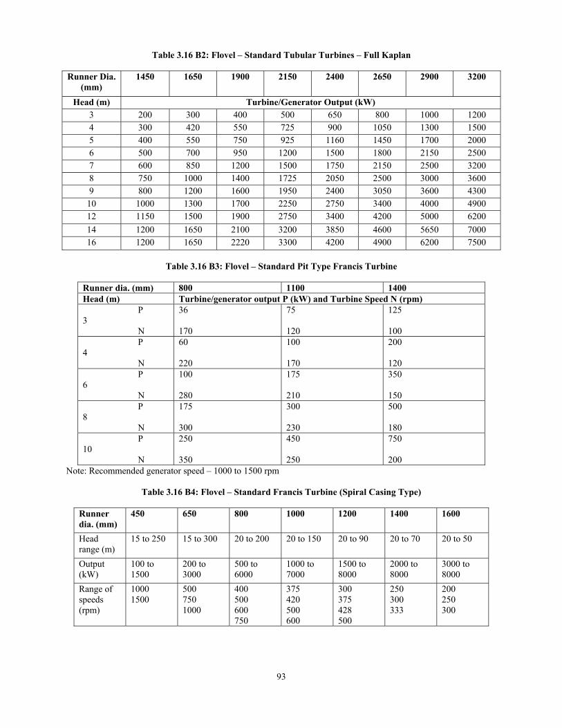
93
Table 3.16 B2: Flovel – Standard Tubular Turbines – Full Kaplan Runner Dia.
(mm) 1450 1650 1900 2150 2400 2650 2900 3200
Head (m) Turbine/Generator Output (kW) 3 200 300 400 500 650 800 1000 1200 4 300 420 550 725 900 1050 1300 1500 5 400 550 750 925 1160 1450 1700 2000 6 500 700 950 1200 1500 1800 2150 2500 7 600 850 1200 1500 1750 2150 2500 3200 8 750 1000 1400 1725 2050 2500 3000 3600 9 800 1200 1600 1950 2400 3050 3600 4300
10 1000 1300 1700 2250 2750 3400 4000 4900 12 1150 1500 1900 2750 3400 4200 5000 6200 14 1200 1650 2100 3200 3850 4600 5650 7000 16 1200 1650 2220 3300 4200 4900 6200 7500
Table 3.16 B3: Flovel – Standard Pit Type Francis Turbine
Runner dia. (mm) 800 1100 1400 Head (m) Turbine/generator output P (kW) and Turbine Speed N (rpm) P 3 N
36 170
75 120
125 100
P 4 N
60 220
100 170
200 120
P 6 N
100 280
175 210
350 150
P 8 N
175 300
300 230
500 180
P 10 N
250 350
450 250
750 200
Note: Recommended generator speed – 1000 to 1500 rpm
Table 3.16 B4: Flovel – Standard Francis Turbine (Spiral Casing Type)
Runner dia. (mm)
450 650 800 1000 1200 1400 1600
Head range (m)
15 to 250 15 to 300 20 to 200 20 to 150 20 to 90 20 to 70 20 to 50
Output (kW)
100 to 1500
200 to 3000
500 to 6000
1000 to 7000
1500 to 8000
2000 to 8000
3000 to 8000
Range of speeds (rpm)
1000 1500
500 750 1000
400 500 600 750
375 420 500 600
300 375 428 500
250 300 333
200 250 300

94
Table 3.16 C1: Jyoti – Standard Tubular Turbines
Runner dia. (mm)
260 600 750 1000 1200 1400 1650 1900 2200 2500
Head (m)
Turbine output Pt (kW)
3 5 28 45 75 125 175 240 330 430 550 4 8 45 80 130 200 280 380 520 730 925 5 11 65 115 190 300 400 560 800 1050 1350 6 15 90 150 250 400 540 750 1000 1400 1800 7 17 115 190 300 460 700 900 1200 1650 2150 8 19 130 210 340 525 750 1000 1400 1900 2500 9 150 240 400 600 825 1150 1600 2150 2900 10 165 270 450 650 920 1250 1750 2350 3200 12.5 205 320 545 800 1200 1600 2200 3100 4000 15 240 380 650 1000 1400 1850 2750 3700 4700 20 320 480 830 1300 1800 2450 3550 4600 6000 25 400 560 900 1450 2250 3150 4200 5900 7200
Table 3.16 C2: Jyoti – Standard Francis
Runner dia. (mm)
350 375 450 525 600 750
Head (m) Turbine Output in Kilowatts 10 25 31 45 65 90 - 15 45 55 80 115 145 230 20 70 85 125 170 225 355 25 100 120 180 240 320 500 30 135 165 240 330 435 680 35 160 200 295 405 530 835 40 130 157 360 500 650 1000 45 160 200 400 390 520 1250 50 180 225 490 680 600 1450 55 320 410 580 530 700 1660 60 375 470 690 940 800 1950 70 305 370 545 725 960 1530 80 360 440 645 890 1180 1830 90 440 540 780 1080 1400 2240 100 500 635 900 1275 1650 2620 110 600 740 1080 1480 1950 3100

95
Table 3.16C3: Jyoti – Standard Pelton Turbines
Runner dia. (mm) 425 600 750 850 1100 Head (m) Turbine Output in Kilowatts
100 40 90 120 170 275 110 50 105 140 195 320 120 55 120 160 224 366 130 60 130 180 250 410 140 70 150 205 285 465 150 80 165 225 315 515 160 85 180 245 345 570 170 95 200 270 380 625 180 100 215 295 415 675 190 110 235 325 450 740 200 120 255 345 485 790 225 140 300 415 575 940 250 165 355 485 675 1100 275 190 410 560 780 1275 300 215 465 635 890 1450 325 245 525 715 1000 1635 350 275 585 800 1120 1825 375 305 650 890 1245 2030 400 - - 975 1360 2235 425 - - 1080 1510 2465 450 - - 1165 1630 2660
Note: Pelton will be double of above figures for two jet pelton
Table 3.16 C4: Jyoti – Standard Turgo Impulse Turbine
Runner dia.
(mm) 350 425 525 600 675 750
Head (m) Turbine Output in Kilowatt 40 41 61 100 131 168 207 50 57 86 140 184 233 290 60 75 113 185 241 308 382 70 94 141 232 304 388 481 80 115 174 284 373 473 587 90 137 207 338 444 564 702
100 161 242 397 521 622 822 110 186 279 458 601 764 948 120 212 319 521 684 868 1078 130 239 359 589 772 982 1217 140 267 404 658 862 1097 1360 150 295 446 727 956 1212 1509 160 325 491 801 1053 1336 1636 170 356 537 878 1152 1465 1822 180 388 585 957 1255 1596 1986 190 421 635 1038 1367 1731 2153 200 455 687 1126 1475 1879 2327
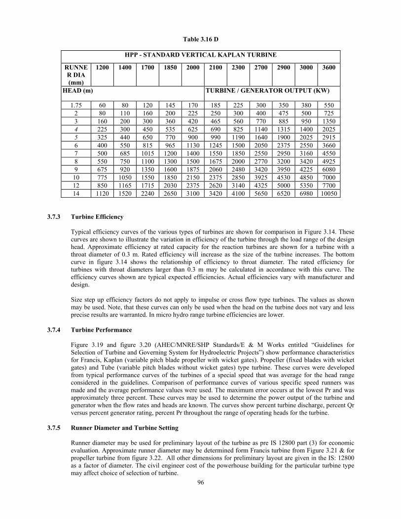
96
Table 3.16 D
HPP - STANDARD VERTICAL KAPLAN TURBINE
RUNNER DIA (mm)
1200
1400
1700
1850
2000
2100
2300
2700
2900
3000
3600
HEAD (m) TURBINE / GENERATOR OUTPUT (KW)
1.75 60 80 120 145 170 185 225 300 350 380 550 2 80 110 160 200 225 250 300 400 475 500 725 3 160 200 300 360 420 465 560 770 885 950 1350 4 225 300 450 535 625 690 825 1140 1315 1400 2025 5 325 440 650 770 900 990 1190 1640 1900 2025 2915 6 400 550 815 965 1130 1245 1500 2050 2375 2550 3660 7 500 685 1015 1200 1400 1550 1850 2550 2950 3160 4550 8 550 750 1100 1300 1500 1675 2000 2770 3200 3420 4925 9 675 920 1350 1600 1875 2060 2480 3420 3950 4225 6080
10 775 1050 1550 1850 2150 2375 2850 3925 4530 4850 7000 12 850 1165 1715 2030 2375 2620 3140 4325 5000 5350 7700 14 1120 1520 2240 2650 3100 3420 4100 5650 6520 6980 10050
3.7.3 Turbine Efficiency
Typical efficiency curves of the various types of turbines are shown for comparison in Figure 3.14. These curves are shown to illustrate the variation in efficiency of the turbine through the load range of the design head. Approximate efficiency at rated capacity for the reaction turbines are shown for a turbine with a throat diameter of 0.3 m. Rated efficiency will increase as the size of the turbine increases. The bottom curve in figure 3.14 shows the relationship of efficiency to throat diameter. The rated efficiency for turbines with throat diameters larger than 0.3 m may be calculated in accordance with this curve. The efficiency curves shown are typical expected efficiencies. Actual efficiencies vary with manufacturer and design. Size step up efficiency factors do not apply to impulse or cross flow type turbines. The values as shown may be used. Note, that these curves can only be used when the head on the turbine does not vary and less precise results are warranted. In micro hydro range turbine efficiencies are lower.
3.7.4 Turbine Performance
Figure 3.19 and figure 3.20 (AHEC/MNRE/SHP Standards/E & M Works entitled “Guidelines for Selection of Turbine and Governing System for Hydroelectric Projects”) show performance characteristics for Francis, Kaplan (variable pitch blade propeller with wicket gates). Propeller (fixed blades with wicket gates) and Tube (variable pitch blades without wicket gates) type turbine. These curves were developed from typical performance curves of the turbines of a special speed that was average for the head range considered in the guidelines. Comparison of performance curves of various specific speed runners was made and the average performance values were used. The maximum error occurs at the lowest Pr and was approximately three percent. These curves may be used to determine the power output of the turbine and generator when the flow rates and heads are known. The curves show percent turbine discharge, percent Qr versus percent generator rating, percent Pr throughout the range of operating heads for the turbine.
3.7.5 Runner Diameter and Turbine Setting
Runner diameter may be used for preliminary layout of the turbine as pre IS 12800 part (3) for economic evaluation. Approximate runner diameter may be determined form Francis turbine from Figure 3.21 & for propeller turbine from figure 3.22. All other dimensions for preliminary layout are given in the IS: 12800 as a factor of diameter. The civil engineer cost of the powerhouse building for the particular turbine type may affect choice of selection of turbine.

97
Pr = γ w, hr , Q r , η t. r η g (kW)
Where, Pr = Rated capacity at hr Hr = Selected Design Head Qr = Turbine Discharge at h r ε Pr η t. r = Turbine efficiency at h r ε Pr η g = Generator efficiency , ( %)
Figure 3.19: Francis and Kaplan performance curves
Pr = γ w, hr , Q r , η t. r η g (kw)
Where, Pr = Rated capacity at hr Hr = Selected Design Head Qr = Turbine Discharge at h r ε Pr η t. r = Turbine efficiency at h r ε Pr η g = Generator efficiency , ( %)
γ w = specific density of water in N/m2 and may be taken 9.804 Figure 3.20: Propeller turbine performance curves

98
NOTES: 1 Estimated turbine runner diameters D are based upon a plant elevation of 600 m. and a tailrace water height
(Hs) of zero. Where Hs = distance between minimum tail water level and exit of runner blades. 2 The estimated runner diameters may be used for both vertical and horizontal Francis turbines. 3 For plant elevations higher than 600 m add 1% to D for each 300 m. Subtract 1% from D for each 300 m.
slower than the 600 m plant elevation.
Figure 3.21 Francis turbine runner diameters (Source: IS 12800)
In Meter

99
NOTES: 1 Estimated turbine runner diameters D are based upon a plant elevation of 600 m.
and a tailrace water height (Hs) of zero. Where Hs = distance between minimum tail water level and exit of runner blades.
2 The estimated runner diameters may be used for both vertical and horizontal Francis turbines. 3 For plant elevations higher than 600 m add 1% to D for each 300 m. Subtract 1% from D for each 300 m.
lower than the 600 m plant elevation.
Figure 3.22: Propeller turbine runner diameters (Source: IS 12800)
In Meter
Hs Tailrace water Height Hs Distance from minimum Tailrace water

100
3.8 SELECTION PROCEDURE OF SMALL HYDRO TURBINE UP TO 5 MW UNIT SIZE
Preliminary selection for type of small hydro turbine can be made from selection chart (figure 3.23) which
is based on IEC –1116 – 1992 as modified by actual data of small hydro installed in the country (table 3.17). Kind (within type) and configuration (horizontal or vertical) may be based on economic consideration including cost of civil works, efficiency etc. and Typical/Standard turbines available for discharge and head in the country as illustrated in the examples.
Table 3.17 Sl. No
Power Station
No. of Units×
Size (MW)
Head (M)
Discharge (M/s)
Year of Coming
Specific Speed Ns in (MHP)
Axial Turbine (Kaplan Turbine) 1. Nidampur 2x0.500 3.000 - 1985 935.54 2. Dauhar 3x0.500 3.500 - 1987 771.58 3. Ganekal 1x0.350 3.690 - 1994 604.27 4. Kakatiya 3x0.230 3.300 - 1987 688.37 5. Kakroi 1x0.100 1.900 - 1988 678.63 6. Jainagra SHP 2x0.500 4.180 29.62
Under Construction
- 7. Shirkhinda SHP 2x0.350 3.186 31.40 739.37 8. Rajapur SHP 2x0.350 4.780 23.00 791.80 9. Amethi SHP 1x0.500 3.218 2.17 740.44 10. Arwal SHP 1x0.500 2.926 24.40 752.21 11. Rampur SHP 1x0.250 2.940 11.97 - 12. Natwar SHP 1x0.250 3.569 9.87 - 13. Mautholi SHP 1x0.400 2.350 25.94 - 14. Katanya SHP 4x0.250 1.780 81.12 - 15. Agnoor SHP 2x0.500 2.744 41.90 2005 - 16. Dhelabagh SHP 2x0.500 2.400 51.80 2006 - 17. Triveni SHP 2x1.500 4.940 72.52 Under
Construction -
Francis Turbine 18. Gumti 3x5.000 40.00 - 1976 283.73 19. Devighat
(Through NHPC)
3x4.800
40.00 -
1983
278.00
20. Gumma 2x1.500 176.75 - 2000 109.17 21. Karnah 2x1.000 36.00 - 1991 325.72 Pelton Turbine 22. Chenani 2x4.600 365.8 - 1975 30.81 23. Thirot 3x1.500 245.0 - 1995 36.29 24. Yazali 3x1.500 277.0 - 1991 31.13
MHP: - Metric horse power units.

101
Note: Details of SHP marked on the chart are given in table 3.17
Figure 3.23 Preliminary Turbine Selection Chart for SHP (Based on IEC: 1116 and Indian Projects Data)

102
3.8.1 Small Hydro in the Range 0.1 MW to 5 MW 1) Field Data Required
a) Discharge data - Q cumecs b) Head - H in meter c) Voltage Net work (415 volts 11 kV/33kV) d) Nearest grid sub-station (optional) – kV and length of interconnecting line
2) Compute kW capacity (P) (from field Data)
P = Q x H x 9.804 x 0.8 3) Fix unit size, number and installed capacity based on data collected. 4) Using kW; H and Q per unit select usable turbine from figure 3.23. 5) In case of turbine in overlapping range determine speed and specific speed relation and determine synchronous
speed based on applicable range of specific speed as per table 3.8. Higher speed machine is cost effective. 6) Select standard/typical available turbine with highest synchronous speed and best efficiency range (table 3.15).
3.8.2 Example of turbine selection (SHP range) 3.8.2.1 Sobla Power House (high head)
Site Data
A common penstock bifurcating at the powerhouse into a wye branch for each power unit is proposed. The length of the penstock system including Y-branch length is 340 meters.
Detail of hydraulic system and basic data for design of turbine as extracted from the specifications is given below: (1) Full reservoir/max. Forebay level (m) 1935 (2) Minimum draw down level (m) 1934 (3) Maximum gross head (static) (m) 198 (4) Maximum net head (m) 185 (5) Minimum net head (m) 184 (6) Rated head (m) 185 (7) Elevation of centre line (m) 1737 (8) Maximum tail race level (m) 1734 (9) Diameter of each penstock (m) 1200 (10) Length of penstock (m) 340 (11) Permissible speed rise 45% (12) Permissible pressure rise 20%
Discharge Data
Stream discharges available for diversion for generation of power at Sobla are given in Table 3.18. There is no storage. Inter connection of power plant implies utilisation of entire power generated for feeding into the grid besides supplying local loads at Sobla and Dharchulla. Accordingly, power generation based on minimum inflows and loading of turbine as percentage of installed capacity is shown in Table-3.19. It is clear that at no time the part load operation is below 67%. Average plant factor during water shortage critical months (December-April) is about 73%.
Inter connection and load characteristics
The powerhouse was proposed to be interconnected by 33 kV lines to Kanchauti and Dharchulla in a ring main for interconnection with Uttarakhand Grid sub-station at Dharchulla.

103
Table –3.18
SOBLA SMALL HYDRO SCHEME DISCHARGES (m3/sec)
S.No. Month 1978 1981 1982 1983 1986 1987 1. January 3.00 3.13 3.49 - 3.10 2. February 3.08 - 3.05 3. March 3.00 3.17 - 2.77
2.85 4. April 4.21 4.16 - 3.16 5. May 5.19 4.50 - >5.0 6. June 9.48 - >5.0 7. July 24.00 - 9.10
8.25 8. August 13.65 11.35 11.90 9. September 8.00 ~ ≥.8 12.10 10. October 6.20 7.71 7.90
8.00 11. November 5.20 ≥.4.8 7.05 12. December 3.10 3.40 5.67
Table –3.19
PART LOAD OPERATION OF SOBLA UNITS
Installation = 2 x3 MW; Rated Head = 185 m
S.No. Month Discharge (Cumecs) Minimum available Power = 9.81 x Q.HE kW
Average plant factor during
month Average Minimum
1. January 3.18 3.00 4356 71% 2. February 3.06 3.05 4428 73.8% 3. March 3.00 2.77 4022 67% 4. April 3.84 3.16 4588 76.4% 5. May 4.89 4.50 6533 100% 6. June 7.00 5.00 7259 100% 7. July 9.00 8.25 6000 100% 8. August 12.30 11.35 6000 100% 9. September 9.30 8.00 6000 100% 10. October 7.27 6.20 6000 100% 11. November 5.68 4.80 6969 100% 12. December 4.05 3.10 4501 75%
NOTE: Overall Efficiency assumed 80%
A small 250 kVA transformer to feed local loads at Sobla was also proposed.
Accordingly, it was considered essential to design the turbines for standalone isolated operation as well as for parallel operation with grid.
Turbine Selection Rated Head (H) = 185 m Rated Power (P) per unit = 3000 kW Discharge = 2.06 cumecs Installation = 2 x 3000 kW As per Figure 3.23 it is seen that either an impulse or Francis Turbine may be suitable. Pelton turbines were originally proposed.

104
Specific speed (ns) is related to rotational speed (n) by specific speed ns ns = n√P/H5/4
= n√3000/(185)5/4 n = 12.45 ns
Runner diameter (D) and speed for various possible values of ns are computed and compared in Table 3.20.
For Pelton Turbine upper practical limit of jet diameter Dj and runner diameter ratio Dj/D = 0.1, then D is 2.1 m which corresponds to a unit with specific speed ns = 21 for single jet pelton and about 30 for two jet turbine. Accordingly, synchronous speed of 375 RPM pelton 2 jet turbine having runner dia of about 1.3 m is possible in case Pelton turbines is used.
Pelton turbines can be coupled directly to 375 r.p.m. (16 pole) generator or 750 r.p.m. (8 pole) generator through speed increasing gears.
For Francis turbine a 6 pole machine 1000 r.p.m. can be set 0.7 m above minimum tailrace water and may be economical to use. Four pole, 1500 r.p.m. generators coupled to 120 (ns) turbines are also feasible and are cavitation free but not recommended due to high speed low inertia in generators and lower setting.
Table 3.20
S. No.
Type of Turbine
Ns (metr
ic)
n(r.p.m.) =12.4 ns (nearest
synchronous)
Runner dia (m)
Setting of runner above
tailrace
Remarks
A.
Single Jet Pelton
10 15 20
125 187.5 250
4.11 2.74 2.06
Above maximum T.W. level
Speed nearest Synchronous
B. Double Jet Pelton
15 20 30
187.5 250 375
2.74 2.06 1.30
C.
Francis
60 750 0.675 +4.0 m i. Nearest synchronous speed ii. Allow 1 m as margin for atmospheric variation for runner setting
80 1000 0.54 +2.2 m 100
1250 (Synchronous speed not possible)
120 1500 0.4 -2.4 m
Comparison of 375 r.p.m. Pelton Turbine and 1000 r.p.m. Francis Turbine 1. Cost of directly coupled Pelton turbine generator set will be more (about 2.5 times that of Francis Turbine
coupled generators) and those coupled through speed increasers by about 1.5 – 2 times. 2. Selection of low specific speed Francis turbine (1000 r.p.m.) with a setting of 0.7 m above minimum
tailrace water level is possible and is liable to be cavitation free. 3. Excessive silt or sand in the water will cause more wear on the runner of an impulse turbine than on the
runners of most reaction turbines. 4. Powerhouse size is liable to be bigger by about 70% for Pelton units. Thereby increasing Civil Engineering
cost. 5. Setting for Pelton turbine nozzle center line is proposed at EL 1737 m and maximum tail water E.L. is 1734
m. Accordingly, if Francis turbine is used, a minimum increase in head of 3 meters is possible. Available head will be further increased during water shortage winter months when tail water is at lower level.
6. Peak efficiency of Pelton turbine is slightly lower than peak efficiency of Francis turbine but part load efficiencies of Pelton turbines are higher. The units do not run below 70% load (Annexure-I) and 80% of the time the units are running above 80-90% load. Accordingly, it is considered that Francis units will generate more energy.

105
7. Penstock length (L) is 340 meter and head (H) is 185 m. According L/H ratio is about 1.8 indicating no water hammer problem for stable speed regulation for Francis turbines and no special advantage for Pelton turbines.
Conclusion & Recommendations
Originally Proposed Pelton turbines were replaced by Francis Turbines and large economies in cost (25-30%) were made.
3.8.2.2 Tejpura SHP (Bihar) (Canal Fall Scheme)
Site Data Discharge Q = 61.05 cubic meters Net head H = 3.46 meters Power P = 9.80 x 61.05 x 3.46 x 0.85 = 1759 kW Installation = 2 x 750 kW
Efficiency SHP range of turbine and generator has been taken as 0.85.
Turbine Selection
As per figure 3.23 only Kaplan/Propeller Axial flow turbine is feasible.
Available standard turbine (table 3.15 A1) is Tubular turbine S type (Full Kaplan) or Semi Kaplan turbine with runners dia. About 2500 meter (BHEL standard Tubular Turbine Figure 3.17) is feasible. This type of turbines requires intake valve for shut off (emergency) as well as draft tube gates for dewatering. It also requires dewatering and drainage arrangement.
Semi Kaplan vertical turbines with siphon intake as shown in figure 3.7 was selected as cheapest and cost effective alternatives (efficient) which does not require intake and draft gates and dewatering arrangements. Detailed comparison of S type tubular turbine with vertical syphon intake turbine is given in table 3.21.
Table 3.21
Comparison of Tubular type and vertical axis siphon intake for ultra low head (below 3 to 4 meter head)
S. No.
Tubular turbine (semi Kaplan)
Vertical axis Siphon intake
Remarks
1. Inlet valve Required Not required 2. Draft tube gate Required Not required 3. Drainage pump Required Not required as setting is
above maximum tailrace
4. Dewatering pump Required Not required as setting is Above tailrace
5. Cost of civil Work High (setting is low) Low 6. Efficiency Tubular turbine efficiency is
1% higher
Guaranteed technical Particulars of the Tejpura Mini HP
Turbines ordered are as follows: Type of turbine – vertical semi Kaplan with siphon intake Rated Head (H) = 3.24 m Rated power (P) = 845 kW (10% overload)
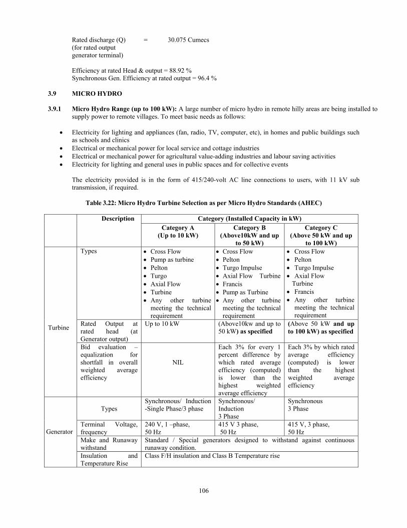
106
Rated discharge (Q) = 30.075 Cumecs (for rated output generator terminal) Efficiency at rated Head & output = 88.92 % Synchronous Gen. Efficiency at rated output = 96.4 %
3.9 MICRO HYDRO 3.9.1 Micro Hydro Range (up to 100 kW): A large number of micro hydro in remote hilly areas are being installed to
supply power to remote villages. To meet basic needs as follows:
• Electricity for lighting and appliances (fan, radio, TV, computer, etc), in homes and public buildings such as schools and clinics
• Electrical or mechanical power for local service and cottage industries • Electrical or mechanical power for agricultural value-adding industries and labour saving activities • Electricity for lighting and general uses in public spaces and for collective events
The electricity provided is in the form of 415/240-volt AC line connections to users, with 11 kV sub transmission, if required.
Table 3.22: Micro Hydro Turbine Selection as per Micro Hydro Standards (AHEC) Description Category (Installed Capacity in kW)
Category A (Up to 10 kW)
Category B (Above10kW and up
to 50 kW)
Category C (Above 50 kW and up
to 100 kW) Turbine
Types • Cross Flow • Pump as turbine • Pelton • Turgo • Axial Flow • Turbine • Any other turbine
meeting the technical requirement
• Cross Flow • Pelton • Turgo Impulse • Axial Flow Turbine • Francis • Pump as Turbine • Any other turbine
meeting the technical requirement
• Cross Flow • Pelton • Turgo Impulse • Axial Flow Turbine • Francis • Any other turbine
meeting the technical requirement
Rated Output at rated head (at Generator output)
Up to 10 kW
(Above10kw and up to 50 kW) as specified
(Above 50 kW and up to 100 kW) as specified
Bid evaluation – equalization for shortfall in overall weighted average efficiency
NIL
Each 3% for every 1 percent difference by which rated average efficiency (computed) is lower than the highest weighted average efficiency
Each 3% by which rated average efficiency (computed) is lower than the highest weighted average efficiency
Generator
Types
Synchronous/ Induction -Single Phase/3 phase
Synchronous/ Induction 3 Phase
Synchronous 3 Phase
Terminal Voltage, frequency
240 V, 1 –phase, 50 Hz
415 V 3 phase, 50 Hz
415 V, 3 phase, 50 Hz
Make and Runaway withstand
Standard / Special generators designed to withstand against continuous runaway condition.
Insulation and Temperature Rise
Class F/H insulation and Class B Temperature rise

107
Description Category (Installed Capacity in kW) Category A
(Up to 10 kW)
Category B (Above10kW and up
to 50 kW)
Category C (Above 50 kW and up
to 100 kW) Overall Efficiency
Minimum required Weighted Average Efficiency of the turbine Generator set (ηT Av) 0.50 x ηT100+0.50 ηT50
45%
50%
60%
3.9.2 Step by step procedure for selection of turbine is detailed below: 1) Obtain Field Data as follows:
a) Discharge data - Q cumecs b) Head - H head in meter c) Voltage Net work (415 volts or 11 kV) d) Nearest grid sub-station (optional) – kV and length of interconnecting line
2) Compute kW capacity (P) with available data from site
P = Q x H x 9.804 x 0.8 3) Fix unit size, number and installed capacity based on data collected and requirement. 4) Using kW; H and Q per unit select usable turbine from figure 3.23. 5) In case of turbine in overlapping range determine speed and specific speed relation and determine
synchronous speed based on applicable range of specific speed as per Para 3.7. Higher speed machine is cost effective.
6) Review turbine limitation and fix turbine type as per micro hydro standard (table 3.22)
Table 3.23: Typical List of Cross Flow Turbine Installed/Proposed in Remote Areas of Uttarakhand Sl. No.
Power Station
Sponsorer/ Manufactu
rer
No. of Units x
Size (MW)
Head (M)
Speed (RPM)
Year/ Likely year of
Commissioning
Specific
Speed (Ns)
Type of Turbine
Type of Generator
1. Dokti Nepal Hydro & Electric Pvt. Ltd.
1x0.02 62.0 1575 Cross Flow Synchronous Generator Horizontal, Kirloskar
2. Kanolgod Nepal Hydro & Electric Pvt. Ltd.
2x0.05 24.5 990 Cross Flow Synchronous Generator Horizontal, Kirloskar
3. Karmi-II Nepal Hydro & Electric Pvt. Ltd.
2x0.025 70 1673 Cross Flow Synchronous Generator Horizontal, Kirloskar
4. Ramgarh Jyoti Ltd. 2x0.05 50 750 Cross Flow Horizontal Jyoti Ltd.5. Ratmoli Nepal
Hydro & Electric Pvt. Ltd.
2x0.025 39 1250 Cross Flow Synchronous Generator Horizontal, Kirloskar
6. Gangotri-I
Vodini Check Republic
2x0.050 23.6 836 Cross Flow AVK

108
3.9.3 Examples of Turbine Selection (micro hydro range)
Napalchyo MHP (Uttarakhand)
Site Data Q = 0.674 cumecs H = 62 m P = 9.80 x 0.674 x 62 x 0.80 = 327.61 kW
Installation proposed based on load survey = 2 x 100 kW
Turbine selection (with following particulars)
Power (P) = 100 kW Head = 62 m
i) As per Figure 3.23 Francis turbine requiring a discharge of 0.2 cumec per turbine is feasible. Peak
efficiency of Francis turbine as per figure 3.5.1 is 90% (at 90% gate). ii) Available standard turbine (table 3.15)
Type Runner dia.
Speed
Peak Approved Efficiency
Flovel Francis 450 mm 1000 to 1500 rpm 90% (table 3.15 B4) Jyoti Turgo Impulse 425 mm 1000 rpm 85% (table 3.15 C4)
According Francis turbine requiring a discharge of 0.2 cumecs per turbine and 0.4 cumecs for 2 turbines required. Civil work may be designed for 0.45 cumecs (10% + 5% margin). Pumps as turbine (mixed flow) can also be used. Check for part load efficiency.
Rong Kong MHP (Uttarakhand)
Site Data Q = 0.441 cumecs
H = 51.0 m Power required = 1 x 50 kW
Available power = 9.80 x 0.441 x 51 x 0.8 = 176.32 kW
Installation Proposed - 1 x 50 kW
Turbine Selection (with following particulars)
Power (P) = 50 kW Head = 51 m
i) As per Figure 3.17) Francis Turbine requiring a discharge of 0.1 cumec per turbine is feasible. Peak
efficiency of Francis turbine as per figure 3.14 is about 90% (at 90% gate) for ii) Available standard turbine (CBI & P- table: 3.15)
Type Runner dia. Speed Peak Approved Efficiency
Flovel Francis 450 1000 to 1500 rpm 90%
Jyoti Turgo Impulse 350 1000 rpm 85%
According Francis turbine requiring a discharge of 0.1 cumec per turbine, civil work may be designed for 0.25 cumec (10% + 5% margin) for two turbine (one for future). Check for part load efficiency.

109
References 1. IS: 12800 (Part 3) – 1991, Guidelines for selection of hydraulic turbine, preliminary dimensioning and
layout of surface hydroelectric powerhouses. 2. IS: 12837 – 1989, Hydraulic turbines for medium and large power houses – guidelines for selection 3. IEC: 1116 – 1992, Electro mechanical equipment guide for small hydroelectric installations. 4. IEC: 609 – 1978, Cavitation pitting evaluation in hydraulic turbines, storage pumps and pump-turbines. 5. IEEE: 1207 – 2004, Guide for the application of turbine governing system for hydroelectric generating
units. 6. IEEE: 125 – 1996, Recommended practice for preparation of equipment specifications for speed governing
of hydraulic turbines intended to drive electric generators 7. United state department of the - Selecting Hydraulic Reaction Turbine Interior Bureau of Reclamation
Engineering Monograph No. 20. 8. Central Board of Irrigation & - Small Hydro Stations Standardization Power India Publication No. 175 -
1985. 9. Central Board of Irrigation & - Manual on Planning and Design of Small Power India Publication No.
Hydroelectric Schemes 280 - 2001. 10. Alternate Hydro Energy Centre – 2005, Micro Hydro Quality Standard Indian Institute of Technology
Roorkee 11. ASME – 1996, Guide to Hydropower Mechanical Design (Book) 12. AHEC/MNRE/SHP Standards/E & M Works entitled “Guidelines for Selection of Turbine and Governing
System for Hydroelectric Projects”