chapter e - lv-distribution
TRANSCRIPT

8/6/2019 Chapter E - LV-Distribution
http://slidepdf.com/reader/full/chapter-e-lv-distribution 1/29
Schneider Electric - Electrical installation guide 2010
E1
© S c h n e
i d e r
E l e c t r i c - a
l l r i g h t s r e s e r v e
d
Chapter ELV Distribution
Contents
Earthing schemes E2 1.1 Earthing connections E2
1.2 Denition of standardised earthing schemes E31.3 Characteristics of TT, TN and IT systems E61.4 Selection criteria for the TT, TN and IT systems E81.5 Choice of earthing method - implementation E101.6 Installation and measurements of earth electrodes E11
The installation system E15 2.1 Distribution switchboards E15
2.2 Cables and busways E18
External inuences (IEC 60364-5-51) E25
3.1 Denition and reference standards E253.2 Classication E253.3 List of external inuences E253.4 Protection provided for enclosed equipment: codes IP and IK E28
1
2
3
EIG_chap_E-2010.indb 1 04/12/2009 11:52:07
8/6/2019 Chapter E - LV-Distribution
http://slidepdf.com/reader/full/chapter-e-lv-distribution 2/29
Schneider Electric - Electrical installation guide 2010
E - Distribution in low-voltage installations
E2
© S c h n e
i d e r
E l e c t r i c - a
l l r i g h t s r e s e r v e
d
1 Earthing schemes
1.1 Earthing connections
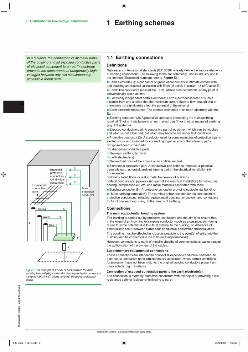
DenitionsNational and international standards (IEC 60364) clearly dene the various elementsof earthing connections. The following terms are commonly used in industry and inthe literature. Bracketed numbers refer to Figure E1 :b Earth electrode (1): A conductor or group of conductors in intimate contact with,and providing an electrical connection with Earth (cf details in section 1.6 of Chapter E.)b Earth: The conductive mass of the Earth, whose electric potential at any point isconventionally taken as zerob Electrically independent earth electrodes: Earth electrodes located at such adistance from one another that the maximum current likely to ow through one ofthem does not signicantly affect the potential of the other(s)b Earth electrode resistance: The contact resistance of an earth electrode with theEarthb Earthing conductor (2): A protective conductor connecting the main ear thingterminal (6) of an installation to an earth electrode (1) or to other means of earthing(e.g. TN systems);b Exposed-conductive-part: A conductive part of equipment which can be touchedand which is not a live part, but which may become live under fault conditionsb Protective conductor (3): A conductor used for some measures of protection against electric shock and intended for connecting together any of the following parts:v Exposed-conductive-partsv Extraneous-conductive-partsv The main earthing terminalv Earth electrode(s)v The earthed point of the source or an articial neutralb Extraneous-conductive-part: A conductive part liable to introduce a potential,generally earth potential, and not forming part of the electrical installation (4).For example:v Non-insulated oors or walls, metal framework of buildingsv Metal conduits and pipework (not part of the electrical installation) for water, gas,
heating, compressed-air, etc. and metal materials associated with themb Bonding conductor (5): A protective conductor providing equipotential bondingb Main earthing terminal (6): The terminal or bar provided for the connection ofprotective conductors, including equipotential bonding conductors, and conductorsfor functional earthing, if any, to the means of earthing.
ConnectionsThe main equipotential bonding systemThe bonding is carried out by protective conductors and the aim is to ensure that,in the event of an incoming extraneous conductor (such as a gas pipe, etc.) beingraised to some potential due to a fault external to the building, no difference ofpotential can occur between extraneous-conductive-parts within the installation.The bonding must be effected as close as possible to the point(s) of entry into thebuilding, and be connected to the main earthing terminal (6).However, connections to earth of metallic sheaths of communications cables require
the authorisation of the owners of the cables.Supplementary equipotential connectionsThese connections are intended to connect all exposed-conductive-parts and allextraneous-conductive-parts simultaneously accessible, when correct conditionsfor protection have not been met, i.e. the original bonding conductors present anunacceptably high resistance.
Connection of exposed-conductive-parts to the earth electrode(s)The connection is made by protective conductors with the object of providing a low-resistance path for fault currents owing to ear th.
In a building, the connection of all metal parts of the building and all exposed conductive parts of electrical equipment to an earth electrode prevents the appearance of dangerously high voltages between any two simultaneously accessible metal parts
Fig. E1 : An example of a block of ats in which the main earthing terminal (6) provides the main equipotential connection; the removable link (7) allows an earth-electrode-resistance check
Branchedprotectiveconductorsto individualconsumers
Extraneousconductiveparts
3
3
3
Mainprotectiveconductor
12
7
6
5
5
5
4
4
Heating
Water
Gas
EIG_chap_E-2010.indb 2 04/12/2009 11:52:07

8/6/2019 Chapter E - LV-Distribution
http://slidepdf.com/reader/full/chapter-e-lv-distribution 3/29
Schneider Electric - Electrical installation guide 2010
E3
© S c h n e
i d e r
E l e c t r i c - a
l l r i g h t s r e s e r v e
d
Components (see Fig. E2 )
Effective connection of all accessible metal xtures and all exposed-conductive-partsof electrical appliances and equipment, is essential for effective protection againstelectric shocks.
Fig. E2 : List of exposed-conductive-parts and extraneous-conductive-parts
Component parts to consider:as exposed-conductive-parts as extraneous-conductive-parts Cableways Elements used in building constructionb Conduits b Metal or reinforced concrete (RC):b Impregnated-paper-insulated lead-covered v Steel-framed structurecable, armoured or unarmoured v Reinforcement rodsb Mineral insulated metal-sheathed cable v Prefabricated RC panels(pyrotenax, etc.) b Surface nishes:Switchgear v Floors and walls in reinforced concrete b cradle of withdrawable switchgear without further surface treatment
Appliancesv Tiled surface
b Exposed metal parts of class 1 insulated b Metallic covering: appliances v Metallic wall covering
Non-electrical elements Building services elements other than electrical b metallic ttings associated with cableways b Metal pipes, conduits, trunking, etc. for gas,(cable trays, cable ladders, etc.) water and heating systems, etc.b Metal objects: b Related metal components (furnaces, tanks,v Close to aerial conductors or to busbars reservoirs, radiators)v In contact with electrical equipment. b Metallic ttings in wash rooms, bathrooms,
toilets, etc.b Metallised papers
Component parts not to be considered:as exposed-conductive-parts as extraneous-conductive-parts Diverse service channels, ducts, etc. b Wooden-block oorsb Conduits made of insulating material b Rubber-covered or linoleum-covered oorsb Mouldings in wood or other insulating b Dry plaster-block partitionmaterial b Brick wallsb Conductors and cables without metallic sheaths b Carpets and wall-to-wall carpetingSwitchgearb Enclosures made of insulating materialAppliancesb All appliances having class II insulationregardless of the type of exterior envelope
1.2 Denition of standardised earthing schemesThe choice of these methods governs the measures necessary for protection againstindirect-contact hazards.The earthing system qualies three originally independent choices made by thedesigner of an electrical distribution system or installation:b The type of connection of the electrical system (that is generally of the neutralconductor) and of the exposed parts to earth electrode(s)b A separate protective conductor or protective conductor and neutral conductorbeing a single conductorb The use of earth fault protection of overcurrent protective switchgear which clearonly relatively high fault currents or the use of additional relays able to detect andclear small insulation fault currents to earthIn practice, these choices have been grouped and standardised as explained below.Each of these choices provides standardised earthing systems with threeadvantages and drawbacks:b Connection of the exposed conductive parts of the equipment and of the neutralconductor to the PE conductor results in equipotentiality and lower overvoltages butincreases earth fault currentsb A separate protective conductor is costly even if it has a small cross-sectional areabut it is much more unlikely to be polluted by voltage drops and harmonics, etc. than a neutral conductor is. Leakage currents are also avoided in extraneous conductive partsb Installation of residual current protective relays or insulation monitoring devices aremuch more sensitive and permits in many circumstances to clear faults before heavydamage occurs (motors, res, electrocution). The protection offered is in additionindependent with respect to changes in an existing installation
The different earthing schemes (often referred to as the type of power system or system earthing arrangements) described characterise the method of earthing the installation
downstream of the secondary winding of a MV/LV transformer and the means used for earthing the exposed conductive-parts of the LV installation supplied from it
1 Earthing schemes
EIG_chap_E-2010.indb 3 04/12/2009 11:52:07
8/6/2019 Chapter E - LV-Distribution
http://slidepdf.com/reader/full/chapter-e-lv-distribution 4/29
Schneider Electric - Electrical installation guide 2010
E - Distribution in low-voltage installations
E4
© S c h n e
i d e r
E l e c t r i c - a
l l r i g h t s r e s e r v e
d
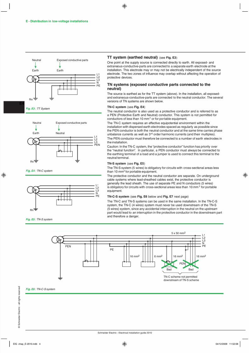
TT system (earthed neutral) (see Fig. E3 )
One point at the supply source is connected directly to earth. All exposed- andextraneous-conductive-parts are connected to a separate earth electrode at theinstallation. This electrode may or may not be electrically independent of the sourceelectrode. The two zones of inuence may overlap without affecting the operation ofprotective devices.
TN systems (exposed conductive parts connected to theneutral)The source is earthed as for the TT system (above). In the installation, all exposed-and extraneous-conductive-parts are connected to the neutral conductor. The several versions of TN systems are shown below.
TN-C system (see Fig. E4 )The neutral conductor is also used as a protective conductor and is referred to asa PEN (Protective Earth and Neutral) conductor. This system is not permitted forconductors of less than 10 mm 2 or for por table equipment.
The TN-C system requires an effective equipotential environment within theinstallation with dispersed earth electrodes spaced as regularly as possible sincethe PEN conductor is both the neutral conductor and at the same time carries phaseunbalance currents as well as 3 rd order harmonic currents (and their multiples).The PEN conductor must therefore be connected to a number of earth electrodes inthe installation.Caution: In the TN-C system, the “protective conductor” function has priority overthe “neutral function”. In particular, a PEN conductor must always be connected tothe earthing terminal of a load and a jumper is used to connect this terminal to theneutral terminal.
TN-S system (see Fig. E5 )The TN-S system (5 wires) is obligatory for circuits with cross-sectional areas lessthan 10 mm 2 for portable equipment.The protective conductor and the neutral conductor are separate. On undergroundcable systems where lead-sheathed cables exist, the protective conductor isgenerally the lead sheath. The use of separate PE and N conductors (5 wires)is obligatory for circuits with cross-sectional areas less than 10 mm 2 for portableequipment.
TN-C-S system (see Fig. E6 below and Fig. E7 next page)The TN-C and TN-S systems can be used in the same installation. In the TN-C-Ssystem, the TN-C (4 wires) system must never be used downstream of the TN-S(5 wires) system, since any accidental interruption in the neutral on the upstreampart would lead to an interruption in the protective conductor in the downstream partand therefore a danger.
L1L2L3NPE
Rn
Neutral
Earth
Exposed conductive parts
Earth
Fig. E3 : TT System
L1L2L3PEN
Rn
Neutral
NeutralEarth
Exposed conductive parts
Fig. E4 : TN-C system
L1L2L3NPE
Rn
Fig. E5 : TN-S system
L1L2L3N
PE
Bad Bad
16 mm 2 6 mm 2 16 mm 2 16 mm 2
PEN
TN-C scheme not permitteddownstream of TN-S scheme
5 x 50 mm 2
PEN PE
Fig. E6 : TN-C-S system
EIG_chap_E-2010.indb 4 04/12/2009 11:52:08
8/6/2019 Chapter E - LV-Distribution
http://slidepdf.com/reader/full/chapter-e-lv-distribution 5/29
Schneider Electric - Electrical installation guide 2010
E5
© S c h n e
i d e r
E l e c t r i c - a
l l r i g h t s r e s e r v e
d
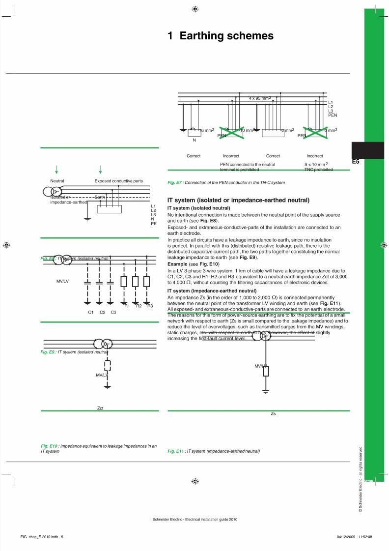
IT system (isolated or impedance-earthed neutral)IT system (isolated neutral)No intentional connection is made between the neutral point of the supply sourceand earth (see Fig. E8 ).Exposed- and extraneous-conductive-parts of the installation are connected to anearth electrode.In practice all circuits have a leakage impedance to earth, since no insulationis perfect. In parallel with this (distributed) resistive leakage path, there is thedistributed capacitive current path, the two paths together constituting the normalleakage impedance to earth (see Fig. E9 ).Example (see Fig. E10 )In a LV 3-phase 3-wire system, 1 km of cable will have a leakage impedance due toC1, C2, C3 and R1, R2 and R3 equivalent to a neutral earth impedance Zct of 3,000to 4,000 Ω , without counting the ltering capacitances of electronic devices.
IT system (impedance-earthed neutral)An impedance Zs (in the order of 1,000 to 2,000 Ω) is connected permanentlybetween the neutral point of the transformer LV winding and earth (see Fig. E11 ).All exposed- and extraneous-conductive-parts are connected to an earth electrode.The reasons for this form of power-source earthing are to x the potential of a smallnetwork with respect to earth (Zs is small compared to the leakage impedance) and to reduce the level of overvoltages, such as transmitted surges from the MV windings,static charges, etc. with respect to earth. It has, however, the effect of slightlyincreasing the rst-fault current level.
Fig. E7 : Connection of the PEN conductor in the TN-C system
L1L2L3PEN
16 mm 2 10 mm 2 6 mm 2 6 mm 2
PEN
2
4 x 95 mm 2
Correct Incorrect Correct Incorrect
PEN connected to the neutralterminal is prohibited
S < 10 mmTNC prohibited
NPEN
Fig. E8 : IT system (isolated neutral)
Fig. E9 : IT system (isolated neutral)
Fig. E10 : Impedance equivalent to leakage impedances in an IT system Fig. E11 : IT system (impedance-earthed neutral)
L1L2L3NPE
Neutral
Isolated orimpedance-earthed
Exposed conductive parts
Earth
R3R2R1
C3C2C1
MV/LV
Zct
MV/LV
MV/LV
Zs
1 Earthing schemes
EIG_chap_E-2010.indb 5 04/12/2009 11:52:08

8/6/2019 Chapter E - LV-Distribution
http://slidepdf.com/reader/full/chapter-e-lv-distribution 6/29
Schneider Electric - Electrical installation guide 2010
E - Distribution in low-voltage installations
E6
© S c h n e
i d e r
E l e c t r i c - a
l l r i g h t s r e s e r v e
d
1.3 Characteristics of TT, TN and IT systems
TT system (see Fig. E12 )The TT system: b Technique for the protection of persons: the exposed conductive parts are earthed and residual current devices (RCDs) are used b Operating technique: interruption for the rst insulation fault
The TN system: b Technique for the protection of persons: v Interconnection and earthing of exposed conductive parts and the neutral are mandatory v Interruption for the rst fault using overcurrent protection (circuit-breakers or fuses) b Operating technique: interruption for the rst insulation fault
Fig. E12 : TT system
Note : If the exposed conductive parts are earthed at a number of points, an RCDmust be installed for each set of circuits connected to a given earth electrode.
Main characteristicsb Simplest solution to design and install. Used in installations supplied directly by thepublic LV distribution network.b Does not require continuous monitoring during operation (a periodic check on theRCDs may be necessary).b Protection is ensured by special devices, the residual current devices (RCD), whichalso prevent the risk of re when they are set to y 500 mA.b Each insulation fault results in an interruption in the supply of power, however theoutage is limited to the faulty circuit by installing the RCDs in series (selective RCDs)or in parallel (circuit selection).b Loads or parts of the installation which, during normal operation, cause high leakage currents, require special measures to avoid nuisance tripping, i.e. supply the loadswith a separation transformer or use specic RCDs (see section 5.1 in chapter F).
TN system (see Fig. E13 and Fig. E14 )
Fig. E14 : TN-S system
Fig. E13 : TN-C system
PEN
NPE
EIG_chap_E-2010.indb 6 04/12/2009 11:52:08

8/6/2019 Chapter E - LV-Distribution
http://slidepdf.com/reader/full/chapter-e-lv-distribution 7/29
Schneider Electric - Electrical installation guide 2010
E7
© S c h n e
i d e r
E l e c t r i c - a
l l r i g h t s r e s e r v e
d
Main characteristics
b Generally speaking, the TN system:v requires the installation of earth electrodes at regular intervals throughout theinstallationv Requires that the initial check on effective tripping for the rst insulation faultbe carried out by calculations during the design stage, followed by mandatorymeasurements to conrm tripping during commissioningv Requires that any modication or extension be designed and carried out by aqualied electricianv May result, in the case of insulation faults, in greater damage to the windings ofrotating machinesv May, on premises with a risk of re, represent a greater danger due to the higherfault currentsb In addition, the TN-C system:v At rst glance, would appear to be less expensive (elimination of a device pole andof a conductor)v Requires the use of xed and rigid conductorsv Is forbidden in certain cases:- Premises with a risk of re- For computer equipment (presence of harmonic currents in the neutral)b In addition, the TN-S system:v May be used even with exible conductors and small conduitsv Due to the separation of the neutral and the protection conductor, provides a cleanPE (computer systems and premises with special risks)
IT system (see Fig. E15 )IT system: b Protection technique: v Interconnection and earthing of exposed conductive parts v Indication of the rst fault by an insulation monitoring device (IMD) v Interruption for the second fault using overcurrent protection (circuit-breakers or fuses) b Operating technique: v Monitoring of the rst insulation fault v Mandatory location and clearing of the fault v Interruption for two simultaneous insulation faults
Fig. E15 : IT system
IMDCardew
Main characteristicsb Solution offering the best continuity of service during operationb Indication of the rst insulation fault, followed by mandatory location and clearing,ensures systematic prevention of supply outages
b Generally used in installations supplied by a private MV/LV or LV/LV transformerb Requires maintenance personnel for monitoring and operationb Requires a high level of insulation in the network (implies breaking up the networkif it is very large and the use of circuit-separation transformers to supply loads withhigh leakage currents)b The check on effective tripping for two simultaneous faults must be carried out bycalculations during the design stage, followed by mandatory measurements duringcommissioning on each group of interconnected exposed conductive partsb Protection of the neutral conductor must be ensured as indicated in section 7.2 ofChapter G
1 Earthing schemes
EIG_chap_E-2010.indb 7 04/12/2009 11:52:09

8/6/2019 Chapter E - LV-Distribution
http://slidepdf.com/reader/full/chapter-e-lv-distribution 8/29
Schneider Electric - Electrical installation guide 2010
E - Distribution in low-voltage installations
E8
© S c h n e
i d e r
E l e c t r i c - a
l l r i g h t s r e s e r v e
d
1.4 Selection criteria for the TT, TN and IT systemsIn terms of the protection of persons, the three system earthing arrangements(SEA) are equivalent if all installation and operating rules are correctly followed.Consequently, selection does not depend on safety criteria.It is by combining all requirements in terms of regulations, continuity of service,operating conditions and the types of network and loads that it is possible todetermine the best system(s) (see Fig. E16 ).Selection is determined by the following factors:b Above all, the applicable regulations which in some cases impose certain types ofSEAb Secondly, the decision of the owner if supply is via a private MV/LV transformer(MV subscription) or the owner has a private energy source (or a separate-windingtransformer)
If the owner effectively has a choice, the decision on the SEA is taken followingdiscussions with the network designer (design ofce, contractor)The discussions must cover:b First of all, the operating requirements (the required level of continuity of service)and the operating conditions (maintenance ensured by electrical personnel or not,in-house personnel or outsourced, etc.)b Secondly, the particular characteristics of the network and the loads(see Fig. E17 next page)
Selection does not depend on safety criteria.The three systems are equivalent in terms of protection of persons if all installation and operating rules are correctly followed.The selection criteria for the best system(s) depend on the regulatory requirements,the required continuity of service, operating conditions and the types of network and loads.
Fig. E16 : Comparison of system earthing arrangements
TT TN-S TN-C IT1 IT2 Comments Electrical characteristicsFault current - - - - - + - - Only the IT system offers virtually negligible rst-fault currentsFault voltage - - - + - In the IT system, the touch voltage is very low for the rst fault,
but is considerable for the secondTouch voltage + / - - - - + - In the TT system, the touch voltage is very low if system is
equipotential, otherwise it is highProtectionProtection of persons against indirect contact + + + + + All SEAs (system earthing arrangement) are equivalent,
if the rules are followedProtection of persons with emergency + - - + - Systems where protection is ensured by RCDs are not sensitivegenerating sets to a change in the internal impedance of the sourceProtection against re (with an RCD) + + Not + + All SEAs in which RCDs can be used are equivalent.
allowed The TN-C system is forbidden on premises where there is a risk of re OvervoltagesContinuous overvoltage + + + - + A phase-to-earth overvoltage is continuous in the IT system
if there is a rst insulation faultTransient overvoltage + - - + - Systems with high fault currents may cause transient overvoltagesOvervoltage if transformer breakdown - + + + + In the TT system, there is a voltage imbalance between(primary/secondary) the different earth electrodes. The other systems are interconnected
to a single earth electrodeElectromagnetic compatibilityImmunity to nearby lightning strikes - + + + + In the TT system, there may be voltage imbalances between
the earth electrodes. In the TT system, there is a signicant currentloop between the two separate earth electrodes
Immunity to lightning strikes on MV lines - - - - - All SEAs are equivalent when a MV line takes a direct lightning strike
Continuous emission of an + + - + + Connection of the PEN to the metal structures of the building iselectromagnetic eld conducive to the continuous generation of electromagnetic eldsTransient non-equipotentiality of the PE + - - + - The PE is no longer equipotential if there is a high fault currentContinuity of serviceInterruption for rst fault - - - + + Only the IT system avoids tripping for the rst insulation faultVoltage dip during insulation fault + - - + - The TN-S, TNC and IT (2 nd fault) systems generate high fault
currents which may cause phase voltage dipsInstallationSpecial devices - + + - - The TT system requires the use of RCDs. The IT system requires
the use of IMDsNumber of earth electrodes - + + - / + - / + The TT system requires two distinct earth electrodes. The IT system
offers a choice between one or two earth electrodesNumber of cables - - + - - Only the TN-C system offers, in certain cases, a reduction in
the number of cablesMaintenanceCost of repairs - - - - - - - - The cost of repairs depends on the damage caused by
the amplitude of the fault currents
Installation damage + - - ++ - Systems causing high fault currents require a check onthe installation after clearing the fault
EIG_chap_E-2010.indb 8 04/12/2009 11:52:09
8/6/2019 Chapter E - LV-Distribution
http://slidepdf.com/reader/full/chapter-e-lv-distribution 9/29
Schneider Electric - Electrical installation guide 2010
E9
© S c h n e
i d e r
E l e c t r i c - a
l l r i g h t s r e s e r v e
d
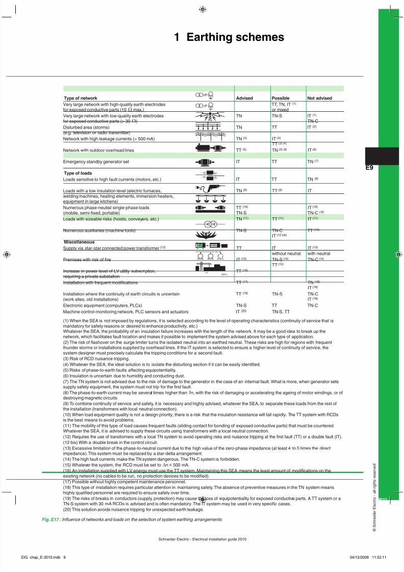
Fig. E17 : Inuence of networks and loads on the selection of system earthing arrangements
(1) When the SEA is not imposed by regulations, it is selected according to the level of operating characteristics (continuity of service that ismandatory for safety reasons or desired to enhance productivity, etc.)Whatever the SEA, the probability of an insulation failure increases with the length of the network. It may be a good idea to break up thenetwork, which facilitates fault location and makes it possible to implement the system advised above for each type of application.(2) The risk of ashover on the surge limiter turns the isolated neutral into an earthed neutral. These risks are high for regions with frequentthunder storms or installations supplied by overhead lines. If the IT system is selected to ensure a higher level of continuity of service, thesystem designer must precisely calculate the tripping conditions for a second fault.(3) Risk of RCD nuisance tripping.(4) Whatever the SEA, the ideal solution is to isolate the disturbing section if it can be easily identied.(5) Risks of phase-to-earth faults affecting equipotentiality.(6) Insulation is uncertain due to humidity and conducting dust.(7) The TN system is not advised due to the risk of damage to the generator in the case of an internal fault. What is more, when generator setssupply safety equipment, the system must not trip for the rst fault.(8) The phase-to-earth current may be several times higher than I n, with the risk of damaging or accelerating the ageing of motor windings, or ofdestroying magnetic circuits.(9) To combine continuity of service and safety, it is necessary and highly advised, whatever the SEA, to separate these loads from the rest ofthe installation (transformers with local neutral connection).(10) When load equipment quality is not a design priority, there is a risk that the insulation resistance will fall rapidly. The TT system with RCDsis the best means to avoid problems.(11) The mobility of this type of load causes frequent faults (sliding contact for bonding of exposed conductive parts) that must be countered.Whatever the SEA, it is advised to supply these circuits using transformers with a local neutral connection.(12) Requires the use of transformers with a local TN system to avoid operating risks and nuisance tripping at the rst fault (TT) or a double fault (IT).(12 bis) With a double break in the control circuit.(13) Excessive limitation of the phase-to-neutral current due to the high value of the zero-phase impedance (at least 4 to 5 times the directimpedance). This system must be replaced by a star-delta arrangement.(14) The high fault currents make the TN system dangerous. The TN-C system is forbidden.(15) Whatever the system, the RCD must be set to ∆n y 500 mA.(16) An installation supplied with LV energy must use the TT system. Maintaining this SEA means the least amount of modications on theexisting network (no cables to be run, no protection devices to be modied).(17) Possible without highly competent maintenance personnel.(18) This type of installation requires particular attention in maintaining safety. The absence of preventive measures in the TN system meanshighly qualied personnel are required to ensure safety over time.(19) The risks of breaks in conductors (supply, protection) may cause the loss of equipotentiality for exposed conductive parts. A TT system or aTN-S system with 30 mA RCDs is advised and is often mandatory. The IT system may be used in very specic cases.(20) This solution avoids nuisance tripping for unexpected earth leakage.
Type of network Advised Possible Not advisedVery large network with high-quality earth electrodes TT, TN, IT (1) for exposed conductive parts (10 Ω max.) or mixedVery large network with low-quality earth electrodes TN TN-S IT (1) for exposed conductive parts (> 30 Ω ) TN-CDisturbed area (storms) TN TT IT (2) (e.g. television or radio transmitter)Network with high leakage currents (> 500 mA) TN (4) IT (4)
TT (3) (4)
Network with outdoor overhead lines TT (5) TN (5) (6) IT (6)
Emergency standby generator set IT TT TN (7)
Type of loadsLoads sensitive to high fault currents (motors, etc.) IT TT TN (8)
Loads with a low insulation level (electric furnaces, TN (9) TT (9) ITwelding machines, heating elements, immersion heaters,equipment in large kitchens)Numerous phase-neutral single-phase loads TT (10) IT (10) (mobile, semi-xed, portable) TN-S TN-C (10) Loads with sizeable risks (hoists, conveyers, etc.) TN (11) TT (11) IT (11)
Numerous auxiliaries (machine tools) TN-S TN-C TT (12) IT (12 bis)
MiscellaneousSupply via star-star connected power transformer (13) TT IT IT (13)
without neutral with neutralPremises with risk of re IT (15) TN-S (15) TN-C (14)
TT (15) Increase in power level of LV utility subscription, TT (16) requiring a private substationInstallation with frequent modications TT (17) TN (18)
IT (18) Installation where the continuity of earth circuits is uncertain TT (19) TN-S TN-C
(work sites, old installations) IT(19)
Electronic equipment (computers, PLCs) TN-S TT TN-CMachine control-monitoring network, PLC sensors and actuators IT (20) TN-S, TT
MV/LVLV
1 Earthing schemes
EIG_chap_E-2010.indb 9 04/12/2009 11:52:11
8/6/2019 Chapter E - LV-Distribution
http://slidepdf.com/reader/full/chapter-e-lv-distribution 10/29
Schneider Electric - Electrical installation guide 2010
E - Distribution in low-voltage installations
E10
© S c h n e
i d e r
E l e c t r i c - a
l l r i g h t s r e s e r v e
d
1.5 Choice of earthing method - implementationAfter consulting applicable regulations, Figures E16 and E17 can be used as an aidin deciding on divisions and possible galvanic isolation of appropriate sections of aproposed installation.
Division of sourceThis technique concerns the use of several transformers instead of employing onehigh-rated unit. In this way, a load that is a source of network disturbances (largemotors, furnaces, etc.) can be supplied by its own transformer.The quality and continuity of supply to the whole installation are thereby improved.The cost of switchgear is reduced (short-circuit current level is lower).The cost-effectiveness of separate transformers must be determined on a case bycase basis.
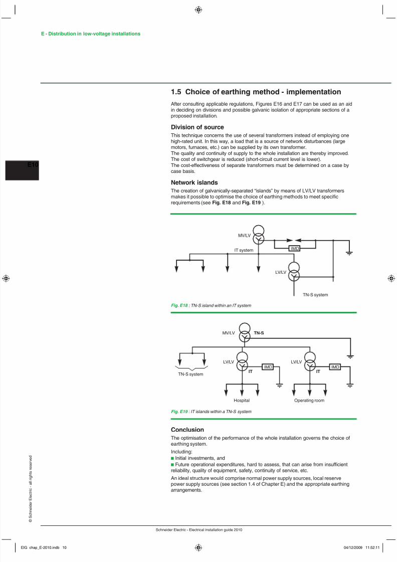
Network islandsThe creation of galvanically-separated “islands” by means of LV/LV transformers
makes it possible to optimise the choice of earthing methods to meet specicrequirements (see Fig. E18 and Fig. E19 ).
Fig. E18 : TN-S island within an IT system
Fig. E19 : IT islands within a TN-S system
IMDIT system
LV/LV
MV/LV
TN-S system
TN-S system
LV/LV
MV/LV TN-S
Operating room
LV/LV
IT IT
Hospital
IMD IMD
ConclusionThe optimisation of the performance of the whole installation governs the choice ofearthing system.
Including:b Initial investments, andb Future operational expenditures, hard to assess, that can arise from insufcientreliability, quality of equipment, safety, continuity of service, etc.
An ideal structure would comprise normal power supply sources, local reservepower supply sources (see section 1.4 of Chapter E) and the appropriate earthing
arrangements.
EIG_chap_E-2010.indb 10 04/12/2009 11:52:11
8/6/2019 Chapter E - LV-Distribution
http://slidepdf.com/reader/full/chapter-e-lv-distribution 11/29
Schneider Electric - Electrical installation guide 2010
E11
© S c h n e
i d e r
E l e c t r i c - a
l l r i g h t s r e s e r v e
d
1.6 Installation and measurements of earthelectrodesThe quality of an earth electrode (resistance as low as possible) depends essentiallyon two factors:b Installation methodb Type of soil
Installation methodsThree common types of installation will be discussed:
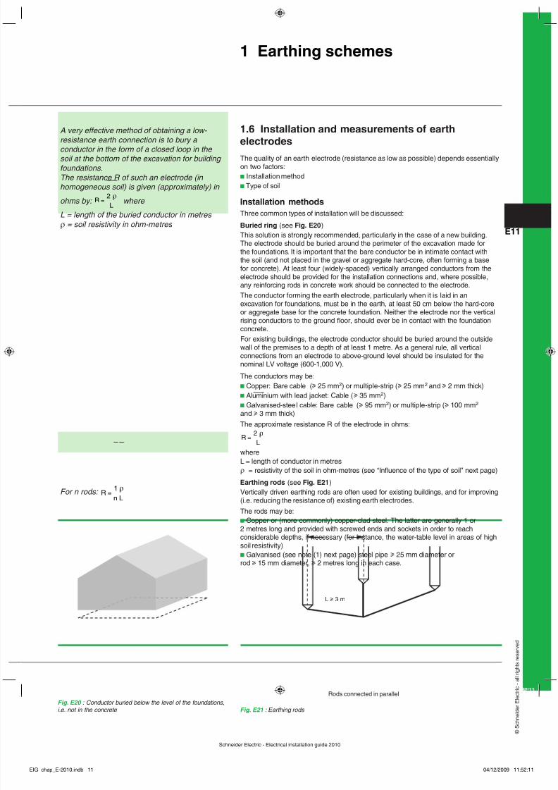
Buried ring (see Fig. E20 )This solution is strongly recommended, particularly in the case of a new building.The electrode should be buried around the perimeter of the excavation made forthe foundations. It is important that the bare conductor be in intimate contact withthe soil (and not placed in the gravel or aggregate hard-core, often forming a basefor concrete). At least four (widely-spaced) vertically arranged conductors from the
electrode should be provided for the installation connections and, where possible,any reinforcing rods in concrete work should be connected to the electrode.The conductor forming the earth electrode, particularly when it is laid in anexcavation for foundations, must be in the earth, at least 50 cm below the hard-coreor aggregate base for the concrete foundation. Neither the electrode nor the verticalrising conductors to the ground oor, should ever be in contact with the foundationconcrete.For existing buildings, the electrode conductor should be buried around the outsidewall of the premises to a depth of at least 1 metre. As a general rule, all verticalconnections from an electrode to above-ground level should be insulated for thenominal LV voltage (600-1,000 V).
The conductors may be:b Copper: Bare cable ( u 25 mm 2) or multiple-strip ( u 25 mm 2 and u 2 mm thick)b Aluminium with lead jacket: Cable ( u 35 mm 2)b Galvanised-steel cable: Bare cable ( u 95 mm 2) or multiple-strip ( u 100 mm 2
and u 3 mm thick)The approximate resistance R of the electrode in ohms:
RL
=
2 l
whereL = length of conductor in metresρ = resistivity of the soil in ohm-metres (see “Inuence of the type of soil” next page)
Earthing rods (see Fig. E21 )Vertically driven earthing rods are often used for existing buildings, and for improving(i.e. reducing the resistance of) existing earth electrodes.The rods may be:b Copper or (more commonly) copper-clad steel. The latter are generally 1 or2 metres long and provided with screwed ends and sockets in order to reachconsiderable depths, if necessary (for instance, the water-table level in areas of highsoil resistivity)b Galvanised (see note (1) next page) steel pipe u 25 mm diameter orrod u 15 mm diameter, u 2 metres long in each case.
A very effective method of obtaining a low- resistance earth connection is to bury a conductor in the form of a closed loop in the soil at the bottom of the excavation for building foundations.The resistance R of such an electrode (in homogeneous soil) is given (approximately) in
ohms by: RL
=
2 l where
L = length of the buried conductor in metres ρ = soil resistivity in ohm-metres
Fig. E20 : Conductor buried below the level of the foundations,i.e. not in the concrete
For n rods: Rn L
=
1 l
Fig. E21 : Earthing rods
Rods connected in parallel
L u 3 m
1 Earthing schemes
EIG_chap_E-2010.indb 11 04/12/2009 11:52:11

8/6/2019 Chapter E - LV-Distribution
http://slidepdf.com/reader/full/chapter-e-lv-distribution 12/29
Schneider Electric - Electrical installation guide 2010
E - Distribution in low-voltage installations
E12
© S c h n e
i d e r
E l e c t r i c - a
l l r i g h t s r e s e r v e
d
It is often necessary to use more than one rod, in which case the spacing between
them should exceed the depth to which they are driven, by a factor of 2 to 3.The total resistance (in homogeneous soil) is then equal to the resistance of one rod,divided by the number of rods in question. The approximate resistance R obtained is:
Rn L
=
1 l
if the distance separating the rods > 4L
whereL = the length of the rod in metresρ = resistivity of the soil in ohm-metres (see “Inuence of the type of soil” below)n = the number of rods
Vertical plates (see Fig. E22 )Rectangular plates, each side of which must be u 0.5 metres, are commonly used asearth electrodes, being buried in a vertical plane such that the centre of the plate isat least 1 metre below the surface of the soil.The plates may be:b Copper of 2 mm thicknessb Galvanised (1) steel of 3 mm thicknessThe resistance R in ohms is given (approximately), by:
RL
=
0.8 l
L = the perimeter of the plate in metresρ = resistivity of the soil in ohm-metres (see “Inuence of the type of soil” below)
Inuence of the type of soil
For a vertical plate electrode: RL
=
0.8 l
(1) Where galvanised conducting materials are used for earthelectrodes, sacricial cathodic protection anodes may benecessary to avoid rapid corrosion of the electrodes wherethe soil is aggressive. Specially prepared magnesium anodes(in a porous sack lled with a suitable “soil”) are available fordirect connection to the electrodes. In such circumstances, aspecialist should be consulted
Measurements on earth electrodes in similar soils are useful to determine the resistivity value to be applied for the design of an earth- electrode system
Fig. E22 : Vertical plate
2 mm thickness (Cu)
Fig. E23 : Resistivity ( Ωm) for different types of soil
Fig. E24 : Average resistivity ( Ωm) values for approximate earth-elect
Type of soil Average value of resistivityin Ωm
Fertile soil, compacted damp ll 50Arid soil, gravel, uncompacted non-uniform ll 500Stoney soil, bare, dry sand, ssured rocks 3,000
Type of soil Mean value of resistivityin Ωm
Swampy soil, bogs 1 - 30Silt alluvium 20 - 100Humus, leaf mould 10 - 150Peat, turf 5 - 100Soft clay 50Marl and compacted clay 100 - 200Jurassic marl 30 - 40Clayey sand 50 - 500Siliceous sand 200 - 300Stoney ground 1,500 - 3,000Grass-covered-stoney sub-soil 300 - 500Chalky soil 100 - 300Limestone 1,000 - 5,000Fissured limestone 500 - 1,000Schist, shale 50 - 300Mica schist 800Granite and sandstone 1,500 - 10,000Modied granite and sandstone 100 - 600
EIG_chap_E-2010.indb 12 04/12/2009 11:52:11
8/6/2019 Chapter E - LV-Distribution
http://slidepdf.com/reader/full/chapter-e-lv-distribution 13/29
Schneider Electric - Electrical installation guide 2010
E13
© S c h n e
i d e r
E l e c t r i c - a
l l r i g h t s r e s e r v e
d
Measurement and constancy of the resistance between an
earth electrode and the earthThe resistance of the electrode/earth interface rarely remains constantAmong the principal factors affecting this resistance are the following:b Humidity of the soilThe seasonal changes in the moisture content of the soil can be signicant at depthsof up to 2 meters.At a depth of 1 metre the resistivity and therefore the resistance can vary by a ratioof 1 to 3 between a wet winter and a dry summer in temperate regionsb FrostFrozen earth can increase the resistivity of the soil by several orders of magnitude.This is one reason for recommending the installation of deep electrodes, in particularin cold climatesb AgeingThe materials used for electrodes will generally deteriorate to some extent forvarious reasons, for example:v Chemical reactions (in acidic or alkaline soils)v Galvanic: due to stray DC currents in the earth, for example from electric railways,etc. or due to dissimilar metals forming primary cells. Different soils acting onsections of the same conductor can also form cathodic and anodic areas withconsequent loss of surface metal from the latter areas. Unfortunately, the mostfavourable conditions for low earth-electrode resistance (i.e. low soil resistivity) arealso those in which galvanic currents can most easily ow.b OxidationBrazed and welded joints and connections are the points most sensitive to oxidation.Thorough cleaning of a newly made joint or connection and wrapping with a suitablegreased-tape binding is a commonly used preventive measure.
Measurement of the earth-electrode resistanceThere must always be one or more removable links to isolate an earth electrode sothat it can be tested.There must always be removable links which allow the earth electrode to be isolated
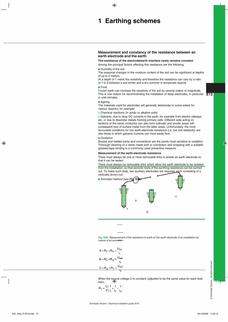
from the installation, so that periodic tests of the ear thing resistance can be carriedout. To make such tests, two auxiliary electrodes are required, each consisting of avertically driven rod.b Ammeter method (see Fig. E25 )
Fig. E25 : Measurement of the resistance to earth of the earth electrode of an installation by means of an ammeter
U
A
t2T
t1
A R RU
i
B R RU
i
C R RU
i
T tTt
t tt t
t Tt T
= + =
= + =
= + =
11
1
1 21 2
2
22
3
When the source voltage U is constant (adjusted to be the same value for each test)
then:R
U
i i iT = + <£¤²
¥¦2
1 1 1
1 3 2
1 Earthing schemes
EIG_chap_E-2010.indb 13 04/12/2009 11:52:12

8/6/2019 Chapter E - LV-Distribution
http://slidepdf.com/reader/full/chapter-e-lv-distribution 14/29
Schneider Electric - Electrical installation guide 2010
E - Distribution in low-voltage installations
E14
© S c h n e
i d e r
E l e c t r i c - a
l l r i g h t s r e s e r v e
d
1 Earthing schemes
In order to avoid errors due to stray earth currents (galvanic -DC- or leakage currents
from power and communication networks and so on) the test current should beAC, but at a different frequency to that of the power system or any of its harmonics.Instruments using hand-driven generators to make these measurements usuallyproduce an AC voltage at a frequency of between 85 Hz and 135 Hz.The distances between the electrodes are not critical and may be in differentdirections from the electrode being tested, according to site conditions. A number oftests at different spacings and directions are generally made to cross-check the testresults.b Use of a direct-reading earthing-resistance ohmmeterThese instruments use a hand-driven or electronic-type AC generator, togetherwith two auxiliary electrodes, the spacing of which must be such that the zone ofinuence of the electrode being tested should not overlap that of the test electrode (C). The test electrode (C) furthest from the electrode (X) under test, passes a currentthrough the earth and the electrode under test, while the second test electrode (P)picks up a voltage. This voltage, measured between (X) and (P), is due to the testcurrent and is a measure of the contact resistance (of the electrode under test) with
earth. It is clear that the distance (X) to (P) must be carefully chosen to give accurateresults. If the distance (X) to (C) is increased, however, the zones of resistance ofelectrodes (X) and (C) become more remote, one from the other, and the curve ofpotential (voltage) becomes more nearly horizontal about the point (O).In practical tests, therefore, the distance (X) to (C) is increased until readings takenwith electrode (P) at three different points, i.e. at (P) and at approximately 5 metreson either side of (P), give similar values. The distance (X) to (P) is generally about0.68 of the distance (X) to (C).
Fig. E26 : Measurement of the resistance to the mass of ear th of electrode (X) using an earth- electrode-testing ohmmeter.
X CP
O
X P
O
C
voltage-drop dueto the resistanceof electrode (X)
voltage-drop dueto the resistanceof electrode (C)
V
G
VG
VG
I
a) the principle of measurement is based on assumed homogeneous soil conditions. Where the
zones of inuence of electrodes C and X overlap, the location of test electrode P is difcult todetermine for satisfactory results.
b) showing the effect on the potential gradient when (X) and (C) are widely spaced. The locationof test electrode P is not critical and can be easily determined.
EIG_chap_E-2010.indb 14 04/12/2009 11:52:12
8/6/2019 Chapter E - LV-Distribution
http://slidepdf.com/reader/full/chapter-e-lv-distribution 15/29
Schneider Electric - Electrical installation guide 2010
E15
© S c h n e
i d e r
E l e c t r i c - a
l l r i g h t s r e s e r v e
d
E - Distribution in low-voltage installations 2 The installation system
2.1 Distribution switchboardsA distribution switchboard is the point at which an incoming-power supply dividesinto separate circuits, each of which is controlled and protected by the fuses orswitchgear of the switchboard. A distribution switchboard is divided into a numberof functional units, each comprising all the electrical and mechanical elementsthat contribute to the fullment of a given function. It represents a key link in thedependability chain.Consequently, the type of distribution switchboard must be perfectly adapted to itsapplication. Its design and construction must comply with applicable standards andworking practises.
The distribution switchboard enclosure provides dual protection:b Protection of switchgear, indicating instruments, relays, fusegear, etc. againstmechanical impacts, vibrations and other external inuences likely to interfere withoperational integrity (EMI, dust, moisture, vermin, etc.)b The protection of human life against the possibility of direct and indirect electricshock (see degree of protection IP and the IK index in section 3.3 of Chapter E).
Types of distribution switchboardsDistribution switchboards may differ according to the kind of application and thedesign principle adopted (notably in the arrangement of the busbars).
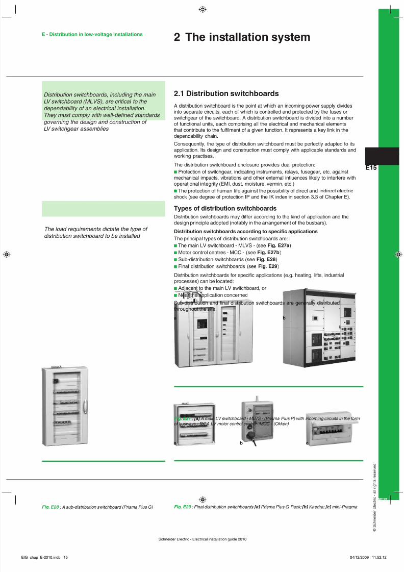
Distribution switchboards according to specic applicationsThe principal types of distribution switchboards are:b The main LV switchboard - MLVS - (see Fig. E27a )b Motor control centres - MCC - (see Fig. E27b )b Sub-distribution switchboards (see Fig. E28 )b Final distribution switchboards (see Fig. E29 )
Distribution switchboards for specic applications (e.g. heating, lifts, industrialprocesses) can be located:b Adjacent to the main LV switchboard, orb Near the application concernedSub-distribution and nal distribution switchboards are generally distributedthroughout the site.
Distribution switchboards, including the main LV switchboard (MLVS), are critical to the dependability of an electrical installation.They must comply with well-dened standards governing the design and construction of LV switchgear assemblies
The load requirements dictate the type of distribution switchboard to be installed
Fig. E27 : [a] A main LV switchboard - MLVS - (Prisma Plus P) with incoming circuits in the form of busways - [b] A LV motor control centre - MCC - (Okken)
Fig. E28 : A sub-distribution switchboard (Prisma Plus G) Fig. E29 : Final distribution switchboards [a] Prisma Plus G Pack; [b] Kaedra; [c] mini-Pragma
a b c
a b
EIG_chap_E-2010.indb 15 04/12/2009 11:52:12
8/6/2019 Chapter E - LV-Distribution
http://slidepdf.com/reader/full/chapter-e-lv-distribution 16/29
Schneider Electric - Electrical installation guide 2010
E - Distribution in low-voltage installations
E16
© S c h n e
i d e r
E l e c t r i c - a
l l r i g h t s r e s e r v e
d
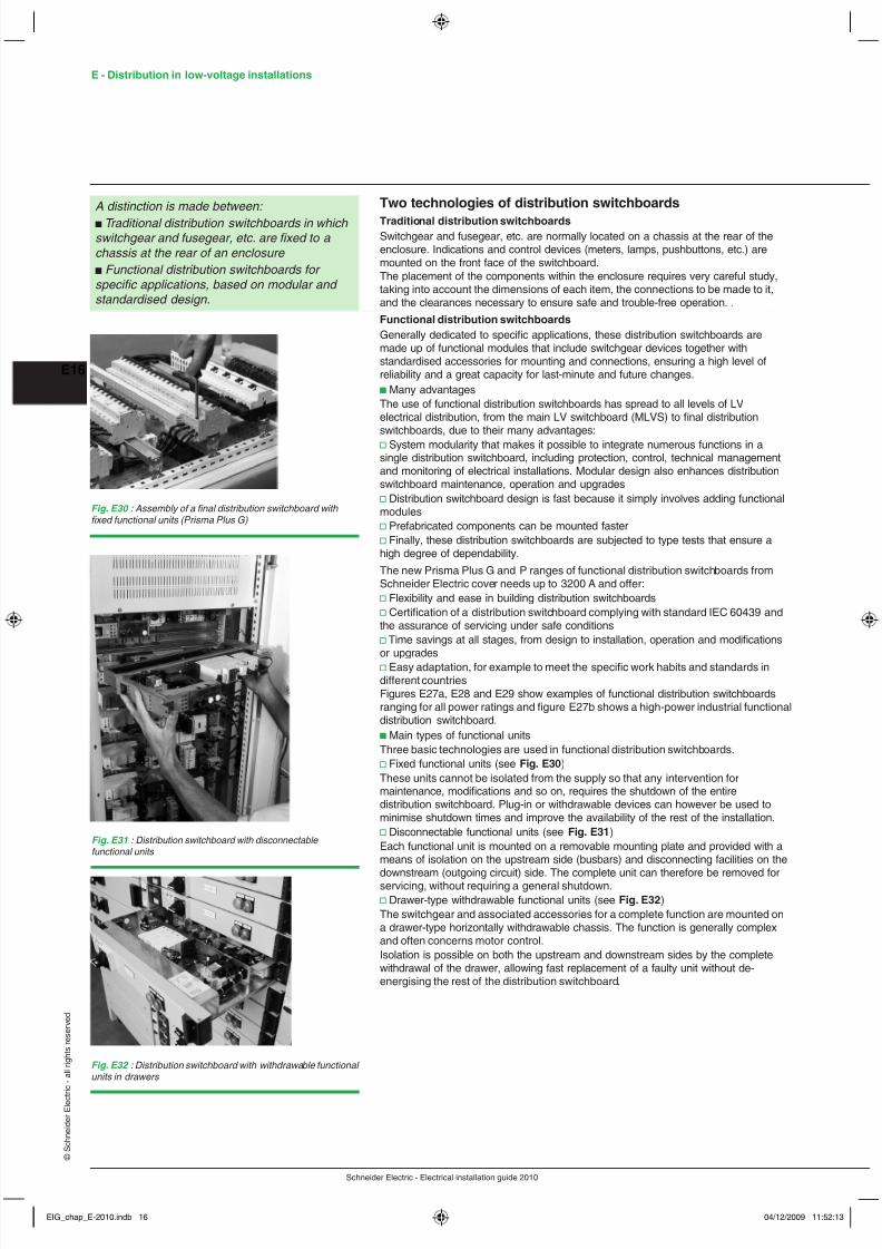
Two technologies of distribution switchboardsTraditional distribution switchboardsSwitchgear and fusegear, etc. are normally located on a chassis at the rear of theenclosure. Indications and control devices (meters, lamps, pushbuttons, etc.) aremounted on the front face of the switchboard.The placement of the components within the enclosure requires very careful study,taking into account the dimensions of each item, the connections to be made to it,and the clearances necessary to ensure safe and trouble-free operation. .Functional distribution switchboardsGenerally dedicated to specic applications, these distribution switchboards aremade up of functional modules that include switchgear devices together withstandardised accessories for mounting and connections, ensuring a high level ofreliability and a great capacity for last-minute and future changes.b Many advantagesThe use of functional distribution switchboards has spread to all levels of LVelectrical distribution, from the main LV switchboard (MLVS) to nal distributionswitchboards, due to their many advantages:v System modularity that makes it possible to integrate numerous functions in asingle distribution switchboard, including protection, control, technical managementand monitoring of electrical installations. Modular design also enhances distributionswitchboard maintenance, operation and upgradesv Distribution switchboard design is fast because it simply involves adding functionalmodulesv Prefabricated components can be mounted fasterv Finally, these distribution switchboards are subjected to type tests that ensure ahigh degree of dependability.The new Prisma Plus G and P ranges of functional distribution switchboards fromSchneider Electric cover needs up to 3200 A and offer:v Flexibility and ease in building distribution switchboardsv Certication of a distribution switchboard complying with standard IEC 60439 andthe assurance of servicing under safe conditionsv Time savings at all stages, from design to installation, operation and modications
or upgradesv Easy adaptation, for example to meet the specic work habits and standards indifferent countriesFigures E27a, E28 and E29 show examples of functional distribution switchboardsranging for all power ratings and gure E27b shows a high-power industrial functionaldistribution switchboard.b Main types of functional unitsThree basic technologies are used in functional distribution switchboards.v Fixed functional units (see Fig. E30 )These units cannot be isolated from the supply so that any intervention formaintenance, modications and so on, requires the shutdown of the entiredistribution switchboard. Plug-in or withdrawable devices can however be used tominimise shutdown times and improve the availability of the rest of the installation.v Disconnectable functional units (see Fig. E31 )Each functional unit is mounted on a removable mounting plate and provided with ameans of isolation on the upstream side (busbars) and disconnecting facilities on the
downstream (outgoing circuit) side. The complete unit can therefore be removed forservicing, without requiring a general shutdown.v Drawer-type withdrawable functional units (see Fig. E32 )The switchgear and associated accessories for a complete function are mounted ona drawer-type horizontally withdrawable chassis. The function is generally complexand often concerns motor control.Isolation is possible on both the upstream and downstream sides by the completewithdrawal of the drawer, allowing fast replacement of a faulty unit without de-energising the rest of the distribution switchboard.
A distinction is made between: b Traditional distribution switchboards in which switchgear and fusegear, etc. are xed to a chassis at the rear of an enclosure b Functional distribution switchboards for specic applications, based on modular and standardised design.
Fig. E30 : Assembly of a nal distribution switchboard with xed functional units (Prisma Plus G)
Fig. E31 : Distribution switchboard with disconnectable functional units
Fig. E32 : Distribution switchboard with withdrawable functional units in drawers
EIG_chap_E-2010.indb 16 04/12/2009 11:52:13

8/6/2019 Chapter E - LV-Distribution
http://slidepdf.com/reader/full/chapter-e-lv-distribution 17/29
Schneider Electric - Electrical installation guide 2010
E17
© S c h n e
i d e r
E l e c t r i c - a
l l r i g h t s r e s e r v e
d
StandardsDifferent standardsCertain types of distribution switchboards (in particular, functional distributionswitchboards) must comply with specic standards according to the application orenvironment involved.The reference international standard is IEC 60439-1 type-tested and partially type-tested assemblies
Standard IEC 60439-1b Categories of assembliesStandard IEC 60439-1 distinguishes between two categories of assemblies:v Type-tested LV switchgear and controlgear assemblies (TTA), which do not divergesignicantly from an established type or system for which conformity is ensured bythe type tests provided in the standardv Partially type-tested LV switchgear and controlgear assemblies (PTTA), which maycontain non-type-tested arrangements provided that the latter are derived from type-tested arrangements
When implemented in compliance with professional work standards andmanufacturer instructions by qualied personnel, they offer the same level of safetyand quality.b Functional unitsThe same standard denes functional units:v Part of an assembly comprising all the electrical and mechanical elements thatcontribute to the fullment of the same functionv The distribution switchboard includes an incoming functional unit and one or morefunctional units for outgoing circuits, depending on the operating requirements of theinstallationWhat is more, distribution switchboard technologies use functional units that may bexed, disconnectable or withdrawable (see section 3.1 of Chapter E).b Forms (see Fig. E33 )Separation of functional units within the assembly is provided by forms that arespecied for different types of operation.The various forms are numbered from 1 to 4 with variations labelled “a” or “b”. Each
step up (from 1 to 4) is cumulative, i.e. a form with a higher number includes thecharacteristics of forms with lower numbers. The standard distinguishes:v Form 1: No separationv Form 2: Separation of busbars from the functional unitsv Form 3: Separation of busbars from the functional units and separation of allfunctional units, one from another, except at their output terminalsv Form 4: As for Form 3, but including separation of the outgoing terminals of allfunctional units, one from anotherThe decision on which form to implement results from an agreement between themanufacturer and the user.The Prima Plus functional range offers solutions for forms 1, 2b, 3b, 4a, 4b.
Compliance with applicable standards is essential in order to ensure an adequate degree of dependability
Three elements of standard IEC 60439-1contribute signicantly to dependability: b Clear denition of functional units b Forms of separation between adjacent functional units in accordance with user requirements b Clearly dened routine tests and type tests
Fig. E33 : Representation of different forms of LV functional distribution switchboards
Form 1 Form 2a Form 2b Form 3a
BusbarSeparation
Form 3b Form 4a Form 4b
2 The installation system
EIG_chap_E-2010.indb 17 04/12/2009 11:52:13

8/6/2019 Chapter E - LV-Distribution
http://slidepdf.com/reader/full/chapter-e-lv-distribution 18/29
Schneider Electric - Electrical installation guide 2010
E - Distribution in low-voltage installations
E18
© S c h n e
i d e r
E l e c t r i c - a
l l r i g h t s r e s e r v e
d
b Type tests and routine tests
They ensure compliance of each distribution switchboard with the standard. Theavailability of test documents certied by independent organisations is a guaranteefor users.
Remote monitoring and control of the electrical installationRemote monitoring and control are no longer limited to large installations.These functions are increasingly used and provide considerable cost savings.The main potential advantages are:b Reductions in energy billsb Reductions in structural costs to maintain the installation in running orderb Better use of the investment, notably concerning optimisation of the installation lifecycleb Greater satisfaction for energy users (in a building or in process industries) due toimproved power availability and/or qualityThe above possibilities are all the more an option given the current deregulation ofthe electrical-energy sector.Modbus is increasingly used as the open standard for communication within thedistribution switchboard and between the distribution switchboard and customerpower monitoring and control applications. Modbus exists in two forms, twisted pair(RS 485) and Ethernet-TCP/IP (IEEE 802.3).The www.modbus.org site presents all bus specications and constantly updates thelist of products and companies using the open industrial standard.The use of web technologies has largely contributed to wider use by drasticallyreducing the cost of accessing these functions through the use of an interface that isnow universal (web pages) and a degree of openness and upgradeability that simplydid not exist just a few years ago.
2.2 Cables and busway trunking
Distribution by insulated conductors and cablesDenitionsb Conductor
A conductor comprises a single metallic core with or without an insulating envelope.
b Cable
A cable is made up of a number of conductors, electrically separated, but joinedmechanically, generally enclosed in a protective exible sheath.
b Cableway
The term cableway refers to conductors and/or cables together with the means ofsupport and protection, etc. for example : cable trays, ladders, ducts, trenches, andso on… are all “cableways”.
Conductor markingConductor identication must always respect the following three rules:b Rule 1The double colour green and yellow is strictly reserved for the PE and PENprotection conductors.b Rule 2v When a circuit comprises a neutral conductor, it must be light blue or marked “1” forcables with more than ve conductorsv When a circuit does not have a neutral conductor, the light blue conductor may beused as a phase conductor if it is part of a cable with more than one conductorb
Rule 3Phase conductors may be any colour except:v Green and yellowv Greenv Yellowv Light blue (see rule 2)
Total accessibility of electrical information and intelligent distribution switchboards are now a reality
Two types of distribution are possible: b By insulated wires and cables b By busbar trunking (busways)
EIG_chap_E-2010.indb 18 04/12/2009 11:52:13

8/6/2019 Chapter E - LV-Distribution
http://slidepdf.com/reader/full/chapter-e-lv-distribution 19/29
Schneider Electric - Electrical installation guide 2010
E19
© S c h n e
i d e r
E l e c t r i c - a
l l r i g h t s r e s e r v e
d
Conductors in a cable are identied either by their colour or by numbers (see Fig. E34 ).
Number of Circuit Fixed cablewaysconductors Insulated conductors Rigid and exible multi-in circuit conductor cables
Ph Ph Pn N PE Ph Ph Ph N PE1 Protection or earth G/Y2 Single-phase between phases b b BL LB
Single-phase between phase and neutral b LB BL LBSingle-phase between phase and neutral b G/Y BL G/Y+ protection conductor
3 Three-phase without neutral b b b BL B LB2 phases + neutral b b LB BL B LB2 phases + protection conductor b b G/Y BL LB G/YSingle-phase between phase and neutral b LB G/Y BL LB G/Y+ protection conductor
4 Three-phase with neutral b b b LB BL B BL LBThree-phase with neutral + protection conductor b b b G/Y BL B LB G/Y2 phases + neutral + protection conductor b b LB G/Y BL B LB G/YThree-phase with PEN conductor b b b G/Y BL B LB G/Y
5 Three-phase + neutral + protection conductor b b b LB G/Y BL B BL LB G/Y> 5 Protection conductor: G/Y - Other conductors: BL: with numbering
The number “1” is reserved for the neutral conductor if it exists
G/Y: Green and yellow BL: Black b : As indicated in rule 3 LB: Light blue B: Brown
Note : If the circuit includes a protection conductor and if the available cable does nothave a green and yellow conductor, the protection conductor may be:b A separate green and yellow conductorb The blue conductor if the circuit does not have a neutral conductorb A black conductor if the circuit has a neutral conductorIn the last two cases, the conductor used must be marked by green and yellowbands or markings at the ends and on all visible lengths of the conductor.Equipment power cords are marked similar to multi-conductor cables (see Fig. E35 ).
Distribution and installation methods (see Fig. E36 )Distribution takes place via cableways that carry single insulated conductors orcables and include a xing system and mechanical protection.
Fig. E34 : Conductor identication according to the type of circuit
Fig. E35 : Conductor identication on a circuit-breaker with a phase and a neutral
Black conductor
N
Light blue conductor Heating, etc.
Building utilities sub-distribution swichboard
Main LV switchboard(MLVS)
Final
distributionswichboard
Floor sub-distributionswichboard
Fig. E36 : Radial distribution using cables in a hotel
2 The installation system
EIG_chap_E-2010.indb 19 04/12/2009 11:52:13
8/6/2019 Chapter E - LV-Distribution
http://slidepdf.com/reader/full/chapter-e-lv-distribution 20/29
Schneider Electric - Electrical installation guide 2010
E - Distribution in low-voltage installations
E20
© S c h n e
i d e r
E l e c t r i c - a
l l r i g h t s r e s e r v e
d
Busbar trunking (busways)Busbar trunking is intended to distribute power (from 20 A to 5000 A) and lighting(in this application, the busbar trunking may play a dual role of supplying electricalpower and physically holding the lights).
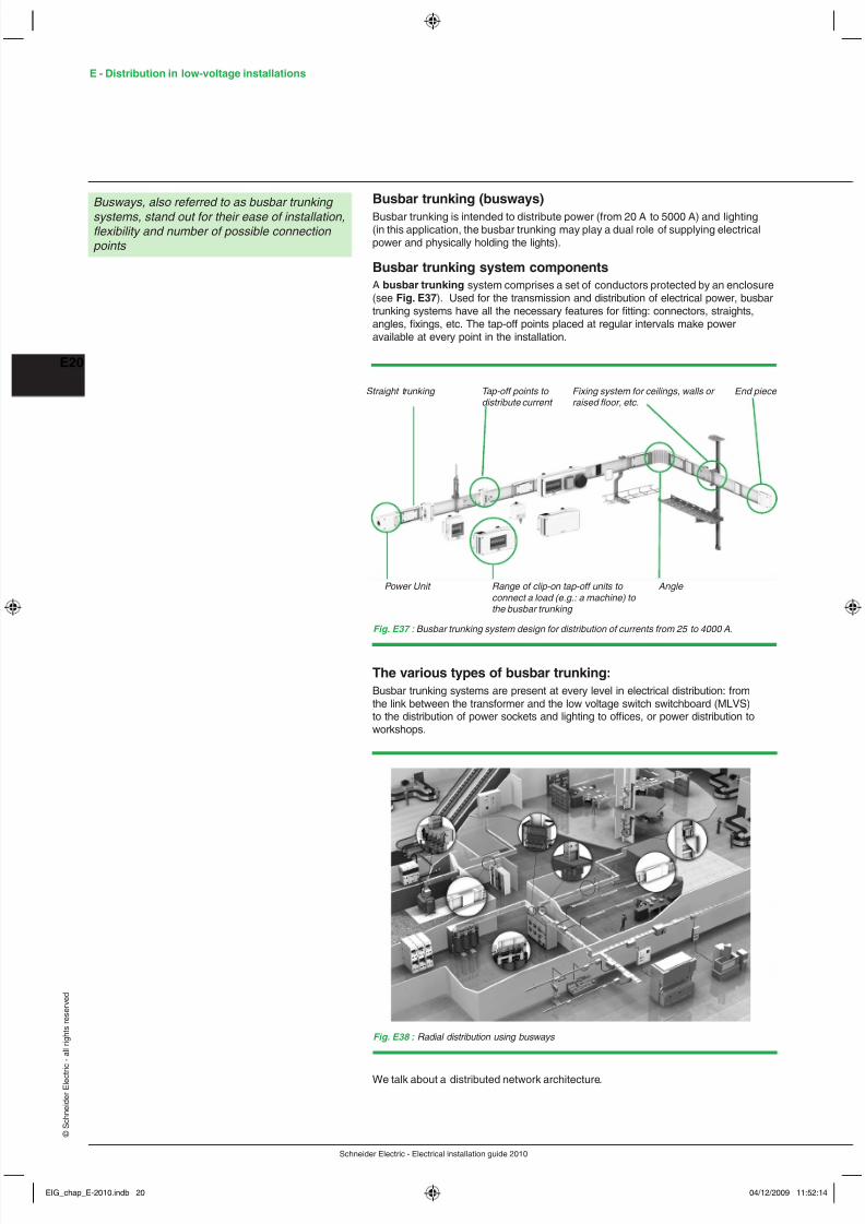
Busbar trunking system componentsA busbar trunking system comprises a set of conductors protected by an enclosure(see Fig. E37 ). Used for the transmission and distribution of electrical power, busbartrunking systems have all the necessary features for tting: connectors, straights,angles, xings, etc. The tap-off points placed at regular intervals make poweravailable at every point in the installation.
Busways, also referred to as busbar trunking systems, stand out for their ease of installation,exibility and number of possible connection points
The various types of busbar trunking:Busbar trunking systems are present at every level in electrical distribution: fromthe link between the transformer and the low voltage switch switchboard (MLVS)to the distribution of power sockets and lighting to ofces, or power distribution toworkshops.
Fig. E37 : Busbar trunking system design for distribution of currents from 25 to 4000 A.
Straight trunking Tap-off points to distribute current
Fixing system for ceilings, walls or raised oor, etc.
End piece
Power Unit Range of clip-on tap-off units to connect a load (e.g.: a machine) to the busbar trunking
Angle
Fig. E38 : Radial distribution using busways
We talk about a distributed network architecture.
EIG_chap_E-2010.indb 20 04/12/2009 11:52:14

8/6/2019 Chapter E - LV-Distribution
http://slidepdf.com/reader/full/chapter-e-lv-distribution 21/29
Schneider Electric - Electrical installation guide 2010
E21
© S c h n e
i d e r
E l e c t r i c - a
l l r i g h t s r e s e r v e
d
There are essentially three categories of busways.
b Transformer to MLVS busbar trunkingInstallation of the busway may be considered as permanent and will most likely neverbe modied. There are no tap-off points.Frequently used for short runs, it is almost always used for ratings above 1,600 / 2,000 A, i.e. when the use of parallel cables makes installation impossible. Buswaysare also used between the MLVS and downstream distribution switchboards.The characteristics of main-distribution busways authorize operational currents from1,000 to 5,000 A and short-circuit withstands up to 150 kA.b Sub-distribution busbar trunking with low or high tap-off densitiesDownstream of main-distribution busbar trunking , two types of applications must besupplied:v Mid-sized premises (industrial workshops with injection presses and metalworkmachines or large supermarkets with heavy loads). The short-circuit and currentlevels can be fairly high (respectively 20 to 70 kA and 100 to 1,000 A)v Small sites (workshops with machine-tools, textile factories with small machines,supermarkets with small loads). The short-circuit and current levels are lower(respectively 10 to 40 kA and 40 to 400 A)Sub-distribution using busbar trunking meets user needs in terms of:v Modications and upgrades given the high number of tap-off pointsv Dependability and continuity of service because tap-off units can be connectedunder energized conditions in complete safetyThe sub-distribution concept is also valid for vertical distribution in the form of 100 to5,000 A risers in tall buildings.b Lighting distribution busbar trunkingLighting circuits can be distributed using two types of busbar trunking according towhether the lighting xtures are suspended from the busbar trunking or not.v busbar trunking designed for the suspension of lighting xturesThese busways supply and support light xtures (industrial reectors, dischargelamps, etc.). They are used in industrial buildings, supermarkets, department storesand warehouses. The busbar trunkings are very rigid and are designed for one ortwo 25 A or 40 A circuits. They have tap-off outlets every 0.5 to 1 m.v busbar trunking not designed for the suspension of lighting xturesSimilar to prefabricated cable systems, these busways are used to supply all typesof lighting xtures secured to the building structure. They are used in commercialbuildings (ofces, shops, restaurants, hotels, etc.), especially in false ceilings. Thebusbar trunking is exible and designed for one 20 A circuit. It has tap-off outletsevery 1.2 m to 3 m.
Busbar trunking systems are suited to the requirements of a large number ofbuildings.b Industrial buildings: garages, workshops, farm buildings, logistic centers, etc.b Commercial areas: stores, shopping malls, supermarkets, hotels, etc.b Tertiary buildings: ofces, schools, hospitals, sports rooms, cruise liners, etc.
StandardsBusbar trunking systems must meet all rules stated in IEC 439-2.This denes the manufacturing arrangements to be complied with in the designof busbar trunking systems (e.g.: temperature rise characteristics, short-circuitwithstand, mechanical strength, etc.) as well as test methods to check them.Standard IEC 439-2 denes 13 compulsory type-tests on congurations or systemcomponents..By assembling the system components on the site according to the assemblyinstructions, the contractor benets from conformity with the standard.
The advantages of busbar trunking systems
Flexibilityb Easy to change conguration (on-site modication to change production lineconguration or extend production areas).b Reusing components (components are kept intact): when an installation is subjectto major modications, the busbar trunking is easy to dismantle and reuse.b Power availability throughout the installation (possibility of having a tap-off pointevery meter).b Wide choice of tap-off units.
2 The installation system
EIG_chap_E-2010.indb 21 04/12/2009 11:52:14
8/6/2019 Chapter E - LV-Distribution
http://slidepdf.com/reader/full/chapter-e-lv-distribution 22/29
Schneider Electric - Electrical installation guide 2010
E - Distribution in low-voltage installations
E22
© S c h n e
i d e r
E l e c t r i c - a
l l r i g h t s r e s e r v e
d
Simplicity
b Design can be carried out independently from the distribution and layout of currentconsumers.b Performances are independent of implementation: the use of cables requires a lotof derating coefcients.b Clear distribution layoutb Reduction of tting time: the trunking system allows tting times to be reduced byup to 50% compared with a traditional cable installation.b Manufacturer’s guarantee.b Controlled execution times: the trunking system concept guarantees that there areno unexpected surprises when tting. The tting time is clearly known in advanceand a quick solution can be provided to any problems on site with this adaptable andscalable equipment.b Easy to implement: modular components that are easy to handle, simple and quickto connect.
Dependabilityb Reliability guaranteed by being factory-builtb Fool-proof unitsb Sequential assembly of straight components and tap-off units making it impossibleto make any mistakes
Continuity of serviceb The large number of tap-off points makes it easy to supply power to any newcurrent consumer. Connecting and disconnecting is quick and can be carried out incomplete safety even when energized. These two operations (adding or modifying)take place without having to stop operations.b Quick and easy fault location since current consumers are near to the lineb Maintenance is non existent or greatly reduced
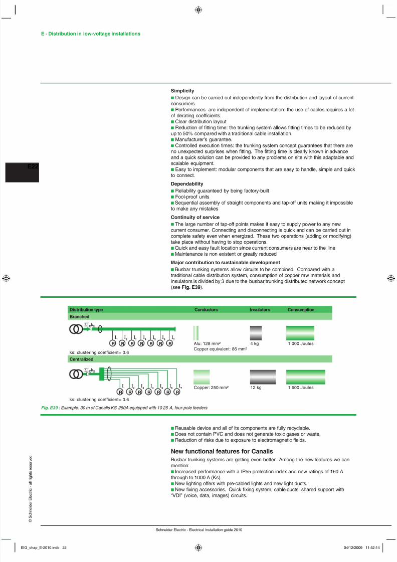
Major contribution to sustainable developmentb Busbar trunking systems allow circuits to be combined. Compared with atraditional cable distribution system, consumption of copper raw materials andinsulators is divided by 3 due to the busbar trunking distributed network concept(see Fig. E39 ).
b Reusable device and all of its components are fully recyclable.b Does not contain PVC and does not generate toxic gases or waste.b Reduction of risks due to exposure to electromagnetic elds.
New functional features for CanalisBusbar trunking systems are getting even better. Among the new features we canmention:b Increased performance with a IP55 protection index and new ratings of 160 Athrough to 1000 A (Ks).b New lighting offers with pre-cabled lights and new light ducts.b New xing accessories. Quick xing system, cable ducts, shared support with“VDI” (voice, data, images) circuits.
I1
I2
I3
I4
I5
I6
I7
I1
I2
I3
I4
I5
I6
I7
Distribution type Conductors Insulators Consumption
1 000 Joules4 kgAlu: 128 mm²
1 600 Joules12 kgCopper: 250 mm²
Copper equivalent: 86 mm²
Branched
ks: clustering coefficient= 0.6
ks: clustering coefficient= 0.6
Centralized
R R R R R R R
R R R R R R R
Σ I xks
Σ I xks
Fig. E39 : Example: 30 m of Canalis KS 250A equipped with 10 25 A, four-pole feeders
EIG_chap_E-2010.indb 22 04/12/2009 11:52:14

8/6/2019 Chapter E - LV-Distribution
http://slidepdf.com/reader/full/chapter-e-lv-distribution 23/29
Schneider Electric - Electrical installation guide 2010
E23
© S c h n e
i d e r
E l e c t r i c - a
l l r i g h t s r e s e r v e
d
Busbar trunking systems are perfectly integrated with the environment:
b white color to enhance the working environment, naturally integrated in a range ofelectrical distribution products.b conformity with European regulations on reducing hazardous materials (RoHS).
Examples of Canalis busbar trunking systems
Fig. E40 : Flexible busbar trunking not capable of supporting light ttings : Canalis KDP (20 A)
Fig. E41 : Rigid busbar trunking able to support light ttings : Canalis KBA or KBB (25 and 40 A)
Fig. E42 : Lighting duct : Canalis KBX (25 A)
Fig. E43 : A busway for medium power distribution : Canalis KN (40 up to 160 A)
2 The installation system
EIG_chap_E-2010.indb 23 04/12/2009 11:52:14
8/6/2019 Chapter E - LV-Distribution
http://slidepdf.com/reader/full/chapter-e-lv-distribution 24/29
Schneider Electric - Electrical installation guide 2010
E - Distribution in low-voltage installations
E24
© S c h n e
i d e r
E l e c t r i c - a
l l r i g h t s r e s e r v e
d
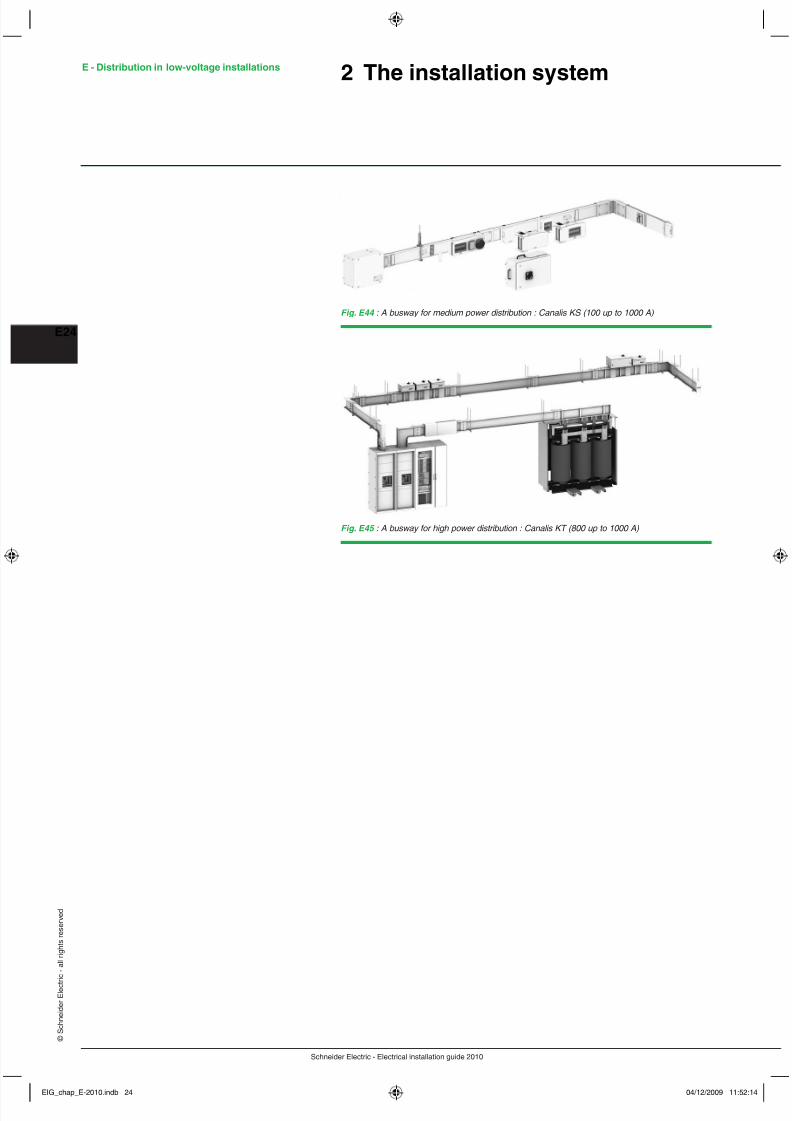
Fig. E44 : A busway for medium power distribution : Canalis KS (100 up to 1000 A)
Fig. E45 : A busway for high power distribution : Canalis KT (800 up to 1000 A)
2 The installation system
EIG_chap_E-2010.indb 24 04/12/2009 11:52:14
8/6/2019 Chapter E - LV-Distribution
http://slidepdf.com/reader/full/chapter-e-lv-distribution 25/29
Schneider Electric - Electrical installation guide 2010
E25
© S c h n e
i d e r
E l e c t r i c - a
l l r i g h t s r e s e r v e
d
3 External inuences(IEC 60364-5-51)
3.1 Denition and reference standardsEvery electrical installation occupies an environment that presents a variable degreeof risk:b For peopleb For the equipment constituting the installationConsequently, environmental conditions inuence the denition and choice ofappropriate installation equipment and the choice of protective measures for thesafety of persons.The environmental conditions are referred to collectively as “external inuences”.Many national standards concerned with external inuences include a classicationscheme which is based on, or which closely resembles, that of international standardIEC 60364-5-51.
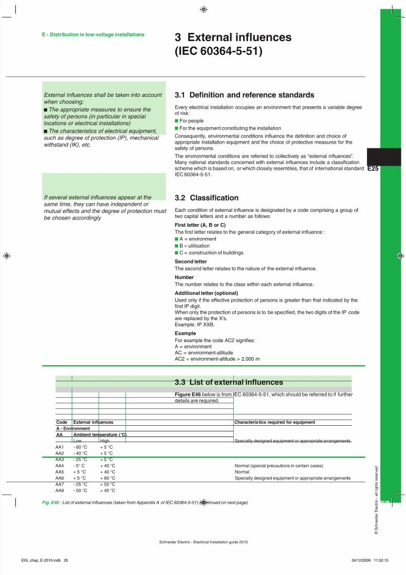
3.2 ClassicationEach condition of external inuence is designated by a code comprising a group oftwo capital letters and a number as follows:
First letter (A, B or C)The rst letter relates to the general category of external inuence :b A = environmentb B = utilisationb C = construction of buildings
Second letterThe second letter relates to the nature of the external inuence.
NumberThe number relates to the class within each external inuence.
Additional letter (optional)
Used only if the effective protection of persons is greater than that indicated by therst IP digit.When only the protection of persons is to be specied, the two digits of the IP codeare replaced by the X’s.Example: IP XXB.
ExampleFor example the code AC2 signies:A = environmentAC = environment-altitudeAC2 = environment-altitude > 2,000 m
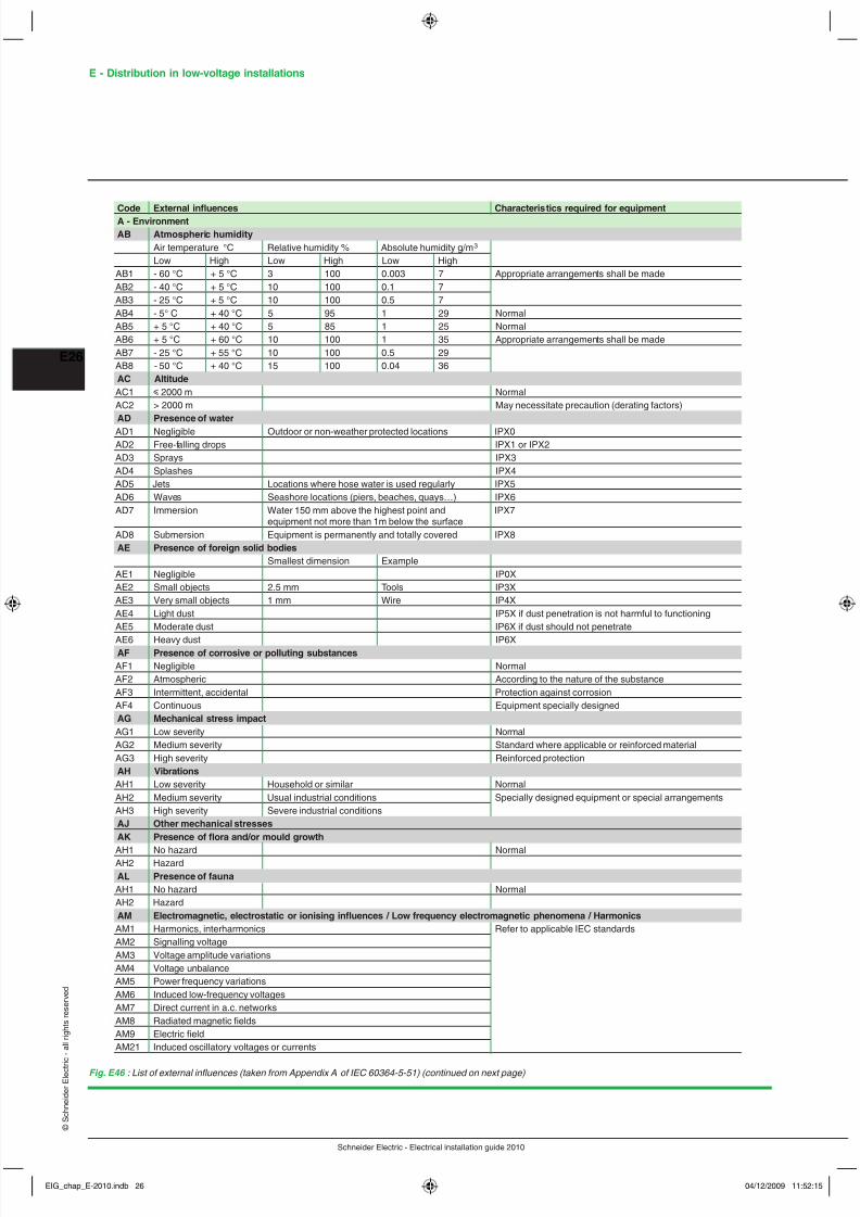
3.3 List of external inuencesFigure E46 below is from IEC 60364-5-51, which should be referred to if further
details are required.
External inuences shall be taken into account when choosing: b The appropriate measures to ensure the safety of persons (in particular in special locations or electrical installations) b The characteristics of electrical equipment,such as degree of protection (IP), mechanical withstand (IK), etc.
If several external inuences appear at the same time, they can have independent or mutual effects and the degree of protection must be chosen accordingly
Code External inuences Characteris tics required for equipmentA - EnvironmentAA Ambient temperature (°C)
Low High Specially designed equipment or appropriate arrangementsAA1 - 60 °C + 5 °CAA2 - 40 °C + 5 °CAA3 - 25 °C + 5 °CAA4 - 5° C + 40 °C Normal (special precautions in certain cases)AA5 + 5 °C + 40 °C NormalAA6 + 5 °C + 60 °C Specially designed equipment or appropriate arrangementsAA7 - 25 °C + 55 °CAA8 - 50 °C + 40 °C
Fig. E46 : List of external inuences (taken from Appendix A of IEC 60364-5-51) (continued on next page)
E - Distribution in low-voltage installations
EIG_chap_E-2010.indb 25 04/12/2009 11:52:15
8/6/2019 Chapter E - LV-Distribution
http://slidepdf.com/reader/full/chapter-e-lv-distribution 26/29
Schneider Electric - Electrical installation guide 2010
E - Distribution in low-voltage installations
E26
© S c h n e
i d e r
E l e c t r i c - a
l l r i g h t s r e s e r v e
d
Code External inuences Characteris tics required for equipmentA - EnvironmentAB Atmospheric humidity
Air temperature °C Relative humidity % Absolute humidity g/m 3 Low High Low High Low High
AB1 - 60 °C + 5 °C 3 100 0.003 7 Appropriate arrangements shall be madeAB2 - 40 °C + 5 °C 10 100 0.1 7AB3 - 25 °C + 5 °C 10 100 0.5 7AB4 - 5° C + 40 °C 5 95 1 29 NormalAB5 + 5 °C + 40 °C 5 85 1 25 NormalAB6 + 5 °C + 60 °C 10 100 1 35 Appropriate arrangements shall be madeAB7 - 25 °C + 55 °C 10 100 0.5 29AB8 - 50 °C + 40 °C 15 100 0.04 36AC AltitudeAC1 y 2000 m NormalAC2 > 2000 m May necessitate precaution (derating factors)AD Presence of waterAD1 Negligible Outdoor or non-weather protected locations IPX0AD2 Free-falling drops IPX1 or IPX2AD3 Sprays IPX3AD4 Splashes IPX4AD5 Jets Locations where hose water is used regularly IPX5AD6 Waves Seashore locations (piers, beaches, quays…) IPX6AD7 Immersion Water 150 mm above the highest point and IPX7
equipment not more than 1m below the surfaceAD8 Submersion Equipment is permanently and totally covered IPX8AE Presence of foreign solid bodies
Smallest dimension ExampleAE1 Negligible IP0XAE2 Small objects 2.5 mm Tools IP3XAE3 Very small objects 1 mm Wire IP4XAE4 Light dust IP5X if dust penetration is not harmful to functioningAE5 Moderate dust IP6X if dust should not penetrate
AE6 Heavy dust IP6XAF Presence of corrosive or polluting substancesAF1 Negligible NormalAF2 Atmospheric According to the nature of the substanceAF3 Intermittent, accidental Protection against corrosionAF4 Continuous Equipment specially designedAG Mechanical stress impactAG1 Low severity NormalAG2 Medium severity Standard where applicable or reinforced materialAG3 High severity Reinforced protectionAH VibrationsAH1 Low severity Household or similar NormalAH2 Medium severity Usual industrial conditions Specially designed equipment or special arrangementsAH3 High severity Severe industrial conditionsAJ Other mechanical stressesAK Presence of ora and/or mould growth
AH1 No hazard NormalAH2 HazardAL Presence of faunaAH1 No hazard NormalAH2 HazardAM Electromagnetic, electrostatic or ionising inuences / Low frequency electromagnetic phenomena / HarmonicsAM1 Harmonics, interharmonics Refer to applicable IEC standardsAM2 Signalling voltageAM3 Voltage amplitude variationsAM4 Voltage unbalanceAM5 Power frequency variationsAM6 Induced low-frequency voltagesAM7 Direct current in a.c. networksAM8 Radiated magnetic eldsAM9 Electric eldAM21 Induced oscillatory voltages or currents
Fig. E46 : List of external inuences (taken from Appendix A of IEC 60364-5-51) (continued on next page)
EIG_chap_E-2010.indb 26 04/12/2009 11:52:15
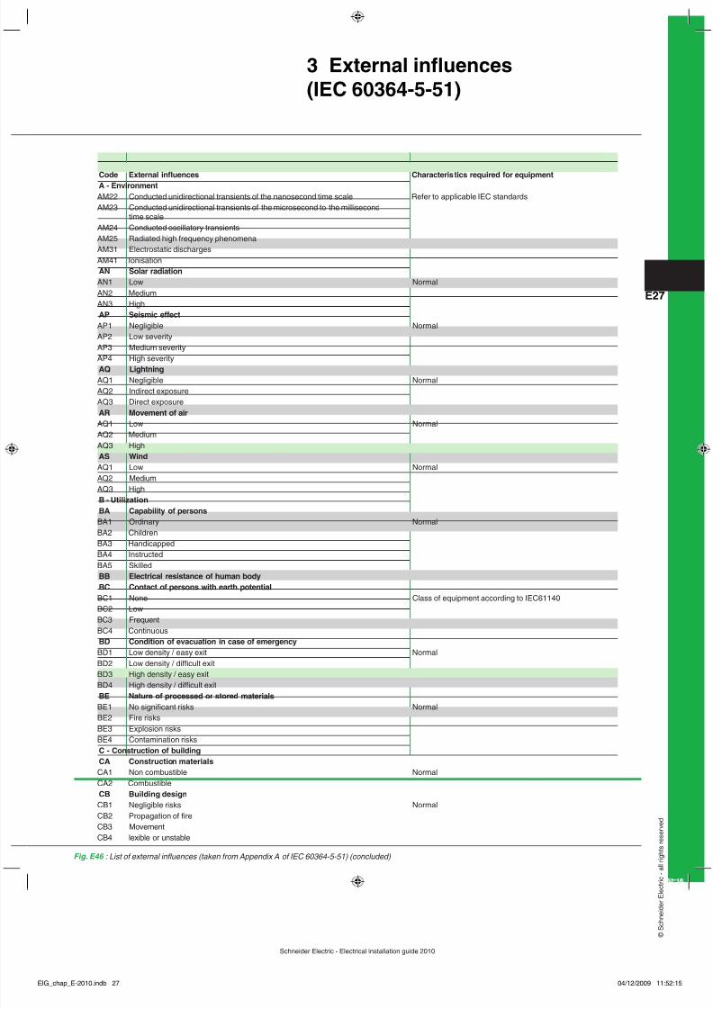
8/6/2019 Chapter E - LV-Distribution
http://slidepdf.com/reader/full/chapter-e-lv-distribution 27/29
Schneider Electric - Electrical installation guide 2010
E27
© S c h n e
i d e r
E l e c t r i c - a
l l r i g h t s r e s e r v e
d
Fig. E46 : List of external inuences (taken from Appendix A of IEC 60364-5-51) (concluded)
Code External inuences Characteris tics required for equipmentA - EnvironmentAM22 Conducted unidirectional transients of the nanosecond time scale Refer to applicable IEC standardsAM23 Conducted unidirectional transients of the microsecond to the millisecond
time scaleAM24 Conducted oscillatory transientsAM25 Radiated high frequency phenomenaAM31 Electrostatic dischargesAM41 IonisationAN Solar radiationAN1 Low NormalAN2 MediumAN3 HighAP Seismic effectAP1 Negligible NormalAP2 Low severityAP3 Medium severityAP4 High severityAQ LightningAQ1 Negligible NormalAQ2 Indirect exposureAQ3 Direct exposureAR Movement of airAQ1 Low NormalAQ2 MediumAQ3 HighAS WindAQ1 Low NormalAQ2 MediumAQ3 HighB - UtilizationBA Capability of personsBA1 Ordinary NormalBA2 ChildrenBA3 HandicappedBA4 InstructedBA5 SkilledBB Electrical resistance of human bodyBC Contact of persons with earth potentialBC1 None Class of equipment according to IEC61140BC2 LowBC3 FrequentBC4 ContinuousBD Condition of evacuation in case of emergencyBD1 Low density / easy exit NormalBD2 Low density / difcult exitBD3 High density / easy exitBD4 High density / difcult exitBE Nature of processed or stored materials
BE1 No signicant risks NormalBE2 Fire risksBE3 Explosion risksBE4 Contamination risksC - Construction of buildingCA Construction materialsCA1 Non combustible NormalCA2 CombustibleCB Building designCB1 Negligible risks NormalCB2 Propagation of reCB3 MovementCB4 lexible or unstable
3 External inuences(IEC 60364-5-51)
EIG_chap_E-2010.indb 27 04/12/2009 11:52:15

8/6/2019 Chapter E - LV-Distribution
http://slidepdf.com/reader/full/chapter-e-lv-distribution 28/29
Schneider Electric - Electrical installation guide 2010
E - Distribution in low-voltage installations
E28
© S c h n e
i d e r
E l e c t r i c - a
l l r i g h t s r e s e r v e
d
3.4 Protection provided for enclosed equipment:codes IP and IKIP code denition (see Fig. E47 )
The degree of protection provided by an enclosure is indicated in the IP code,recommended in IEC 60529.Protection is afforded against the following external inuences:b Penetration by solid bodiesb Protection of persons against access to live partsb Protection against the ingress of dustb Protection against the ingress of liquids
Note : the IP code applies to electrical equipment for voltages up to and including72.5 kV.
Elements of the IP Code and their meaningsA brief description of the IP Code elements is given in the following chart(see Fig. E48 ).
Fig. E47 : IP Code arrangement
IP 2 3 C H
Code letters(International Protection)
First characteristic numeral
(numerals 0 to 6, or letter X)Second characteristic numeral(numerals 0 to 6, or letter X)
Additional letter (optional)(letters A, B, C, D)
Supplementary letter (optional)(letters H, M, S, W)
Where a characteristic numeral is not required to be specified,it shall be replaced by the letter "X" ("XX" if both numeralsare omitted). Additional letters and/or supplementary lettersmay be omitted without replacement.
Code letters
Element Numeralsor letters
Meaning for the protectionof equipment
Meaning for theprotection of persons
Firstcharacteristicnumeral 0
123456
IP
Against ingress of solid foreignobjects
(non-protected)u 50 mm diameteru 12.5 mm diameteru 2.5 mm diameteru 1.0 mm diameterDust-protectedDust-tight
Against access tohazardous parts with
(non-protected)Back of handFingerToolWireWireWire
Additionalletter(optional) A
BCD
Against access tohazardous parts with
back of handFingerToolWire
Supplementaryletter(optional)
HMSW
Supplementary information specific to:High-voltage apparatusMotion during water testStationary during water testWeather conditions
Secondcharacteristicnumeral 0
12345678
Against ingress of water withharmful effects
(non-protected)Vertically drippingDripping (15° tilted)SprayingSplashingJettingPowerful jettingTemporary immersionContinuous immersion
Fig. E48 : Elements of the IP Code
EIG_chap_E-2010.indb 28 04/12/2009 11:52:15
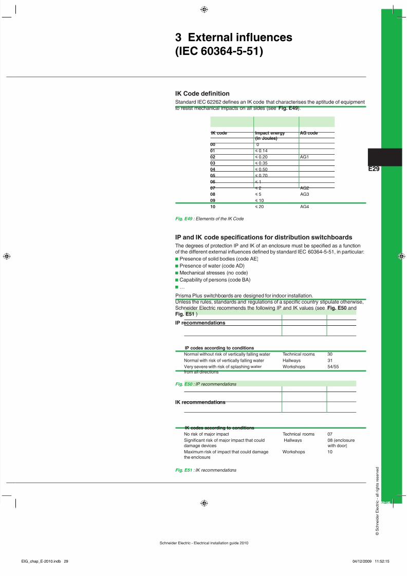
8/6/2019 Chapter E - LV-Distribution
http://slidepdf.com/reader/full/chapter-e-lv-distribution 29/29
E29
e i d e r
E l e c t r i c - a
l l r i g h t s r e s e r v e
d
3 External inuences(IEC 60364-5-51)
IK Code denitionStandard IEC 62262 denes an IK code that characterises the aptitude of equipmentto resist mechanical impacts on all sides (see Fig. E49 ).
Fig. E49 : Elements of the IK Code
IK code Impact energy AG code(in Joules)
00 001 y 0.1402 y 0.20 AG103 y 0.3504 y 0.5005 y 0.7006 y 107 y 2 AG208 y 5 AG3
09 y 1010 y 20 AG4
IP and IK code specications for distribution switchboardsThe degrees of protection IP and IK of an enclosure must be specied as a functionof the different external inuences dened by standard IEC 60364-5-51, in particular:b Presence of solid bodies (code AE)b Presence of water (code AD)b Mechanical stresses (no code)b Capability of persons (code BA)b …
Prisma Plus switchboards are designed for indoor installation.
Unless the rules, standards and regulations of a specic country stipulate otherwise,Schneider Electric recommends the following IP and IK values (see Fig. E50 andFig. E51 )
IP recommendations
Fig. E50 : IP recommendations
Fig. E51 : IK recommendations
IK recommendations
IP codes according to conditionsNormal without risk of vertically falling water Technical rooms 30Normal with risk of vertically falling water Hallways 31Very severe with risk of splashing water Workshops 54/55from all directions
IK codes according to conditionsNo risk of major impact Technical rooms 07Signicant risk of major impact that could Hallways 08 (enclosuredamage devices with door)Maximum risk of impact that could damage Workshops 10the enclosure