chapter history of chipsealing one in new zealand 1 history of chipsealing in new zealand 1.1 before...
TRANSCRIPT

C H A P T E RO N E
History of Chipsealingin New Zealand
Chap t e r 1 H i s t o r y o f Ch i p s e a l i n g i n New Z e a l a nd
1.1 Before Chipsealing_____________________________________________________________________________________________________________3
1.2 Chipsealing comes to New Zealand ____________________________________________________________________________________3
1.3 Principles and Philosophy of Chipsealing ______________________________________________________________________________4
1.4 Changes in Binder Materials _______________________________________________________________________________________________7
1.5 Changes in Aggregate Materials _________________________________________________________________________________________13
1.6 Changes in Equipment______________________________________________________________________________________________________14
1.7 Changes in Procedures_____________________________________________________________________________________________________19
1.8 References ______________________________________________________________________________________________________________________22
Previous page: Laying a first coat chipseal on a New Zealand state highway in the 1970s. From left is a9-ton 3-wheeled roller, a bitumen distributor and on the right a fan-tailed chip spreader on a shortwheel-based tip truck. Photo from NRB (1974)
1
3C h i p s e a l i n g i n N e w Z e a l a n d
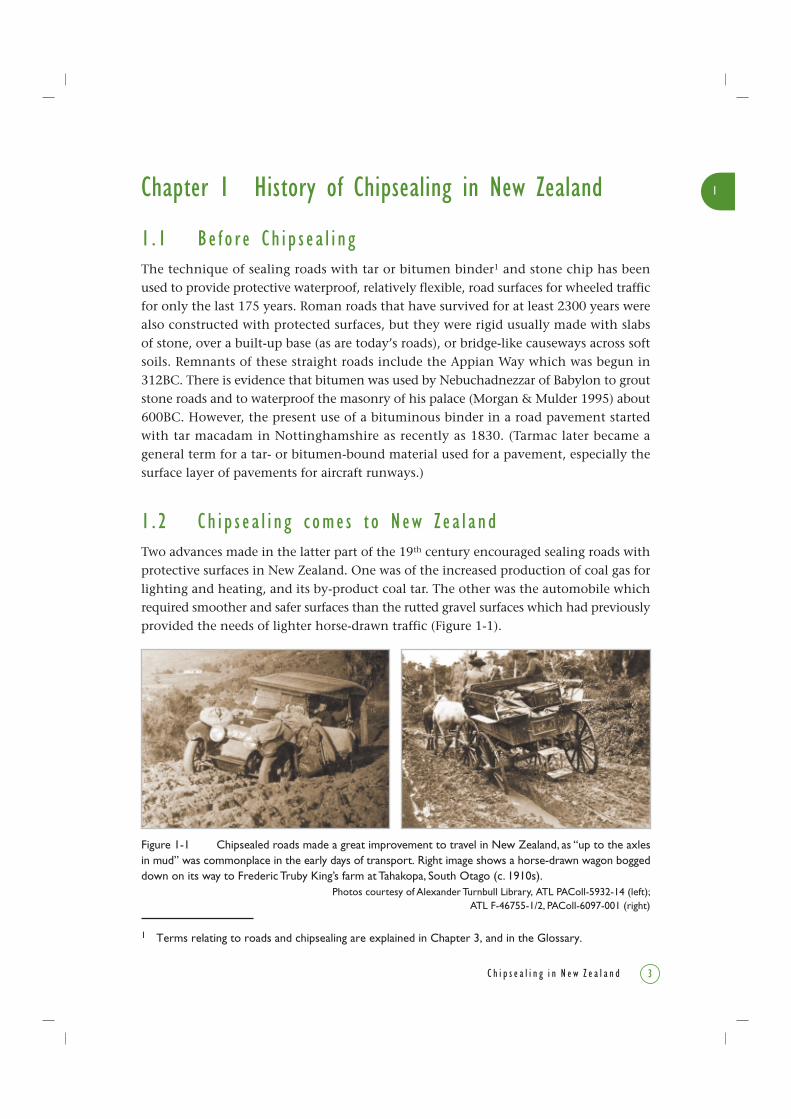
Figure 1-1 Chipsealed roads made a great improvement to travel in New Zealand, as “up to the axlesin mud” was commonplace in the early days of transport. Right image shows a horse-drawn wagon boggeddown on its way to Frederic Truby King’s farm at Tahakopa, South Otago (c. 1910s).
Photos courtesy of Alexander Turnbull Library, ATL PAColl-5932-14 (left);ATL F-46755-1/2, PAColl-6097-001 (right)
Chapter 1 History of Chipsealing in New Zealand
1 . 1 Be f o r e Ch i p s e a l i n gThe technique of sealing roads with tar or bitumen binder1 and stone chip has beenused to provide protective waterproof, relatively flexible, road surfaces for wheeled trafficfor only the last 175 years. Roman roads that have survived for at least 2300 years werealso constructed with protected surfaces, but they were rigid usually made with slabsof stone, over a built-up base (as are today’s roads), or bridge-like causeways across softsoils. Remnants of these straight roads include the Appian Way which was begun in312BC. There is evidence that bitumen was used by Nebuchadnezzar of Babylon to groutstone roads and to waterproof the masonry of his palace (Morgan & Mulder 1995) about600BC. However, the present use of a bituminous binder in a road pavement startedwith tar macadam in Nottinghamshire as recently as 1830. (Tarmac later became ageneral term for a tar- or bitumen-bound material used for a pavement, especially thesurface layer of pavements for aircraft runways.)
1 . 2 Ch i p s e a l i n g c ome s t o New Z e a l a ndTwo advances made in the latter part of the 19th century encouraged sealing roads withprotective surfaces in New Zealand. One was of the increased production of coal gas forlighting and heating, and its by-product coal tar. The other was the automobile whichrequired smoother and safer surfaces than the rutted gravel surfaces which had previouslyprovided the needs of lighter horse-drawn traffic (Figure 1-1).
1 Terms relating to roads and chipsealing are explained in Chapter 3, and in the Glossary.
1
4 C h i p s e a l i n g i n N e w Z e a l a n d
A contributing reason to the wide use of chipsealing in New Zealand in the early
20th century was its lower production costs. Chipseals could be constructed using simple
plant and some local materials. It was a process which could be applied over a conventional
water-bound macadam pavement (which then became the basecourse of stones of the
pavement), yet provided enough flexibility to resist cracking under normal service by
traffic. It was and remains simpler and cheaper, requiring much less energy than making
the bitumen-bound macadams used in the northern hemisphere for which the stone
chip (or aggregate) and the binder have to be heated together and for which specialist
mixing plant is required. As a result, the technique of chipsealing roads has been
developed to a high degree and consequently New Zealand’s roading engineers are
acknowledged to be among the world leaders in this field.
From about 1880 in New Zealand, tar from the local gasworks was sprayed over roads
or footpaths and covered with locally sourced chips to make a dust-proof and waterproof
surfacing. The technique was to hand-spray about a quarter of a gallon per square yard
(about 1.35 /m2) of binder over the compacted basecourse. This produced a film of
binder about 0.05 inches (1.35 mm) thick. It was covered with bigger than sand-sized
gravel or crushed chips, and the seal was compacted with a roller. Gradual refinement
in techniques evolved.
1 . 3 P r i n c i p l e s and Ph i l o s o phy o f Ch i p s e a l i n gDuring the early 1930s, development of the automobile and increase in traffic volumes
created a demand for improvement in the quality of road surfaces. About this time,
testing and experimenting with aggregates and bitumen were carried out in an effort
to be more quantitative, and less dependent on the skill of the on-site manager, overseer
or foreperson, and on their eye for best practice.
1830Tar macadam used on
Nottinghamshire roads
600BCNebuchadnezzar
uses bitumen
312BCAppian Way is built
Key:
BSM Bituminous Sealing ManualMHB Main Highways BoardMOW Ministry of WorksMWD Ministry of Works & DevelopmentNRB National Roads BoardPWD Public Works DepartmentRAMM Road Assessment & Maintenance
ManagementNZ State HighwayAuthorities
NZ Chipsealingevents
Overseas events
1800AD
1
5C h i p s e a l i n g i n N e w Z e a l a n d
A more scientific approach to the design of the chipseal road surface was needed. When
F.M. Hanson presented his paper Bituminous surface treatment of rural highways to the
Conference of the NZ Society of Civil Engineers, in 1935, he made the first steps to
quantify the chipseal concept.
Based on his methodical approach for this paper, chipsealing as we know it today was
established. The precept was that the rate of application of the binder should be designed
to rise 2/3rd up the height of the stone chips, to leave a non-skid, non-glare stone surface
to take the wear and stress imposed by traffic.
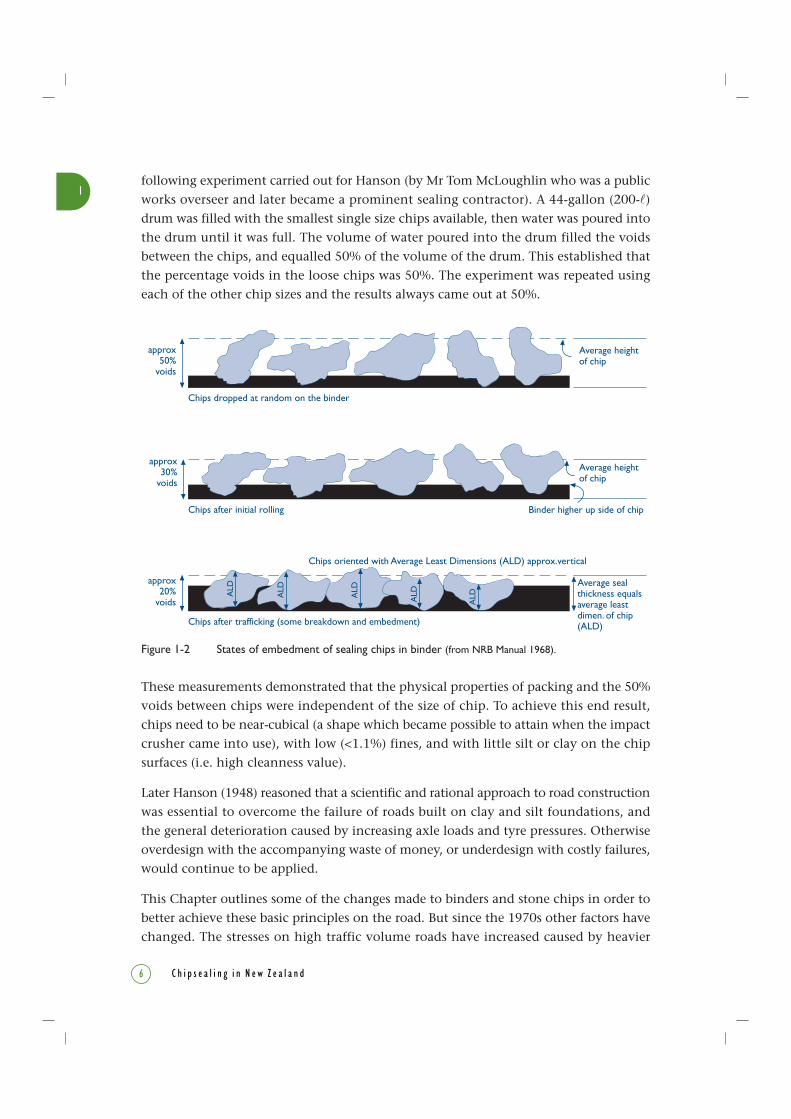
Hanson’s principles relating to the theory of surface sealing (Figure 1-2) were summarised
in the National Roads Board (NRB) 1968 Manual of sealing and paving practice, and are
quoted here:
1. When sufficient chips are placed on a seal binder to ultimately bed into a single layer
in shoulder to shoulder contact, the percentage of voids in the initially laid loose state
is approximately 50%. This is reduced to about 30% by construction rolling, and to
20% by traffic compaction.
2. The amount of binder required bears a definite relationship to the volume of voids
in the cover stone aggregate; the quantity should be such that between 65 and 70%
of the voids in the finally compacted layer of sealing chips are filled with binder.
3. The average depth of the layer of stone chips forming the cover coat, after construction
and traffic compaction is approximately equal to the average least dimension (ALD)
of the chips used.
Although the principles that Hanson promoted are still current, refinement to the values
of voids has been made as more information has been gathered.
The whole basis of Hanson’s theoretical approach relied on the concept that the percentage
of voids in the loose state as initially laid was 50%. This concept was verified by the
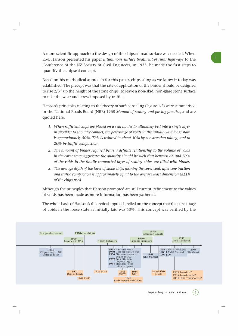
1880sChipsealing in NZ
using coal tar
1900Bitumen in USA
1910s Emulsions
1930s Polymers
1924 MHB
2005This book
1960sCationic Emulsions
1970sAdhesion Agents
1985 RAMM Developed1988 RAMM Manual1993 BSM
1995Shell Handbook
1901Dept of Roads
1909 PWD
1943MOW
1948PWD merged with MOW
1935 Hanson’s work1950 Coal tar phased out1956 Bitumen research
begins in NZ1959 Bulk bitumen
imports begin1964 Marsden Point
refinery opens
1954NRB
First production of:
1968NRB Manual
1989 Transit NZ1995 Transfund NZ2004 Land Transport NZ
late-1970sMWD
1
6 C h i p s e a l i n g i n N e w Z e a l a n d
Figure 1-2 States of embedment of sealing chips in binder (from NRB Manual 1968).
These measurements demonstrated that the physical properties of packing and the 50%
voids between chips were independent of the size of chip. To achieve this end result,
chips need to be near-cubical (a shape which became possible to attain when the impact
crusher came into use), with low (<1.1%) fines, and with little silt or clay on the chip
surfaces (i.e. high cleanness value).
Later Hanson (1948) reasoned that a scientific and rational approach to road construction
was essential to overcome the failure of roads built on clay and silt foundations, and
the general deterioration caused by increasing axle loads and tyre pressures. Otherwise
overdesign with the accompanying waste of money, or underdesign with costly failures,
would continue to be applied.
This Chapter outlines some of the changes made to binders and stone chips in order to
better achieve these basic principles on the road. But since the 1970s other factors have
changed. The stresses on high traffic volume roads have increased caused by heavier
approx30%
voids
Average heightof chip
Chips dropped at random on the binder
approx50%
voids
Average sealthickness equalsaverage leastdimen. of chip(ALD)
approx20%
voids
Chips after initial rolling Binder higher up side of chip
Chips oriented with Average Least Dimensions (ALD) approx.vertical
Chips after trafficking (some breakdown and embedment)
ALD
ALD
ALD
ALD
ALD
Average heightof chip
following experiment carried out for Hanson (by Mr Tom McLoughlin who was a public
works overseer and later became a prominent sealing contractor). A 44-gallon (200- )
drum was filled with the smallest single size chips available, then water was poured into
the drum until it was full. The volume of water poured into the drum filled the voids
between the chips, and equalled 50% of the volume of the drum. This established that
the percentage voids in the loose chips was 50%. The experiment was repeated using
each of the other chip sizes and the results always came out at 50%.
1
7C h i p s e a l i n g i n N e w Z e a l a n d
vehicles (up to 43 tonnes gross laden weight, or 42.3 tons), the introduction of power
steering and braking, single drive axles, higher engine power and higher speeds. These
began pushing the technology to its limit. The demands have led to the development and
use of more shear-resistant chipseal systems (e.g. modified binders, multicoat seals). The
research that continues today on developing relevant algorithms for modern bituminous-
surfacing seal design is described in subsequent chapters of this book. Where the demands
are too high for chipseals, other surfacing techniques such as hot mix asphalt have to be
employed, and only brief reference is made to these techniques in this book.
Sealed roads were originally confined to towns but the total length of chipsealed road
steadily increased each year until by 2004 the length of state highways under chipseal
recorded in Transit NZ’s annual statistics report was 10,837 km, with the last 20 km to
Cape Reinga still to be sealed. This is only 12% of the total length (including state
highways) of the road network in New Zealand, which now totals 92,760 km. The Road
Controlling Authorities (RCAs) who administer the other 81,923 km or 88% are the 74
Local Authorities (i.e. City Councils and District Councils).
1 . 4 Chang e s i n B i n d e r Ma t e r i a l sCoal tar
Coal tar is a by-product from local gasworks and was the earliest and only binder used
in New Zealand until about 1910, when bitumens for roading use first became available.
With about 65 gasworks around the country it was generally available. Most New Zealand
tar was undistilled and was hazardous to work with. Workers, such as the spray operator
on the hand spraybar, could suffer skin burns from the high sulphur content and other
chemicals in the tar, and it was known to be carcinogenic. Distilled tar that came mainly
from England was more benign and also had a longer life in the pavement. However
substantial processing was required to produce a tar having good road-making properties,
and many works did only minimal processing. Their tars were suitable for use as primers
which were exposed for only a short time before being covered by the next seal coat,
and the requirements were less stringent and far easier to meet.
This source was dwindling by the mid-1950s by which time only four or five gasworks
were producing roading tar, although imported English coal tar was used in Central
Otago as late as 1959 for first coat sealing on state highways.
Bitumen
Bitumen is the heavy residue obtained from refining crude oil. Roading grade bitumen
had been first produced in the United States around 1900, and it came into use in New
Zealand as a more durable and less temperature-sensitive material than coal tar about
1914, just before World War 1. The first bitumen to be applied to a pavement in New
Zealand was undertaken by Sir Russell Matthews in 1914 in New Plymouth. The bitumen
1
8 C h i p s e a l i n g i n N e w Z e a l a n d
had been imported in wooden stave barrels from the Standard Oil Company from
Pennsylvania, USA. Until the early 1930s, crude oil products (penetration grades used for
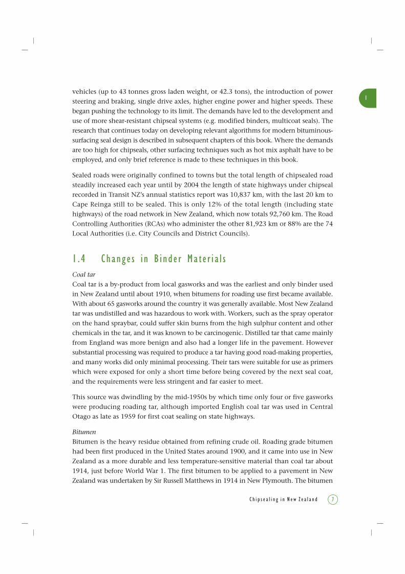
chipsealing, emulsions and hot mixes, and more fluid road oils) were imported mainly
from the United States. The barrel staves made a good fuel for the decanters or heaters(tar kettles) which supplied bitumen to the sprayers (Figure 1-3) and were horse-drawn(Figure 1-4). A rope extended along the side of the heater to the horse-hitching harnessso that the horse could be released if the bitumen caught fire. This escape mechanism wasused in the case of explosion or fire so if the horse bolted it did not drag the unit up thestreet leaving a trail of catastrophes for both workers and bystanders.
Figure 1-3 This bitumen heating kettle (left) being used in Taranaki was the way to heat bitumen inthe 1920s. The fire, stoked with staves from empty bitumen barrels, was in the firebox under the kettle.The firebox gases passed around all sides of the kettle. Photo courtesy of John Matthews, Technix Group Ltd
As if the task was not hazardous enough, the bitumen was pumped by a hand-operatedgear pump, and that was a very unpleasant occupation for the person standing alongsidethe uninsulated surfaces of the tar kettle.
Supplies of lighter penetration grade bitumens, road oils and some cutbacks came fromCalifornia and Mexico, and were transported in 44 gallon (200 ) steel drums (which laterfound an interesting end use, see box). They were the main sources until after World War 2,about 1945, after which sources widened to include the Middle East oilfields.
1
9C h i p s e a l i n g i n N e w Z e a l a n d
As road building activity increased, annual bitumen use doubled between 1950 and
1960 to about 60,000 tons (about 60,960 tonnes). It levelled out at about 100,000 tons
(about 101,600 tonnes) per year until 1980. To cope with this increase, and in anticipation
of refining oil in New Zealand, the first imports of bitumen in bulk tankers were in 1959
from Venezuela. In 1964, the New Zealand Refining Company’s plant at Marsden Point,
near Whangarei, opened and took over supply almost totally, with distribution to a total
of nine ports around New Zealand. To maintain consistency in meeting the fairly
demanding requirements set by Specification (see box) NRB M/1 (now TNZ M/1:1995)
and to be within the refinery’s capability, crude oil generally came from a single Middle
East oilfield which could be accessed by the main New Zealand oil companies. Its higher
price was a relatively small disadvantage compared to the high transport costs of
importing the bitumen.
Later containers were steel drums and, rather than waste them, at least one
contractor had a sideline business recycling them. He used equipment that peeled
the ends off the drums (similar to a can opener), opened up the cylindrical part
of the drum which was then passed through a flat roller, and finally through a
corrugated roller. The product, bitumen-coated corrugated sheets, proved very
popular for sheds and other buildings, particularly in the country.
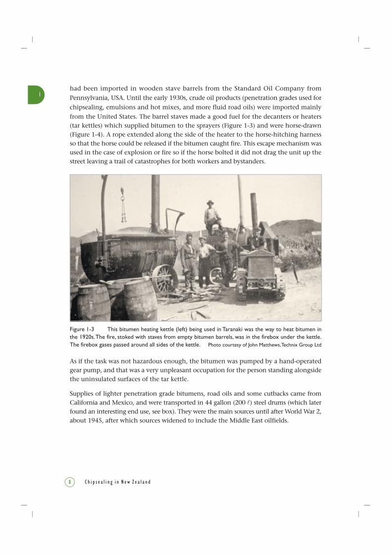
Figure 1-4 Draughthorse-drawn bitumen hand sprayer ready for sealing the main street of Opunake,Taranaki, in the 1920s. Photo courtesy of Feaver Collection, Puke Ariki Museum Archives, New Plymouth
1
10 C h i p s e a l i n g i n N e w Z e a l a n d
Extensive research into bitumen properties began at Dominion Laboratory (forerunner
of Chemistry Division, Department of Scientific & Industrial Research) in 1956, and
continues today mainly at Opus Central Laboratories, but also at the laboratories of
some of New Zealand’s roading contractor companies. Much of the information given
in Chapters 4, 8 and 9 is based on this New Zealand research.
Bulk bitumen created some logistical transport problems that had a major effect on the
bitumen contracting industry and road making generally. Initially the bitumen was
transported by ship to bulk storage facilities at the ports of Auckland, Wellington and
Lyttelton. Transport by road in the early 1960s was limited by law to 90 miles (145 km)
from the port facility. If bitumen had to be carried beyond that 90-mile limit, it had to
be transported by rail tankwagons that were purpose-built. The rail wagons were fitted
with flame tubes that could be fired by demountable burners for heating the bitumen.
However, purpose-built spray tankers were exempt from this 90-mile restriction, and
soon some contractors had fitted pumps and sprayer equipment to their bulk-bitumen
delivery tankers in order to circumvent these regulations.
Oil industry policy was to supply bitumen heated only to a pumpable viscosity (a
temperature which is too cold for spraying). In practice this meant that each independent
contractor had to have dedicated heating plant to raise the bitumen to spraying
temperature. This discouraged small contractors from becoming involved, causing
instability in the bitumen contracting industry over many years, and affecting the rate
of road building.
Another problem arising from importing crude oil for processing at the refinery was the
need to balance the barrel, i.e. for every barrel of crude oil refined there had to be a
market for each by-product (e.g. for kerosene, petrol, diesel, bitumen). This meant that
each oil company was required to balance the marketing of its products with the yield
from the crude oil imported.
Specifications and Notes contain best practice for the construction and
maintenance of roads, including specifications for materials, paving, surfacings,
road formation, equipment, traffic control, and quality assurance. In this book,
most of the specifications are dated to indicate the versions that are referred to.
Specifications referred to in contract and other works documents may not be
dated to indicate that the latest version available is the one that applies. Specifications
and Notes have been produced by the various government departments which
have been responsible for the nation’s roads over the last 105 years.

1
C h i p s e a l i n g i n N e w Z e a l a n d 11
Bitumen Emulsions
Bitumen emulsions were first used in New Zealand about 1910, and their use today is
detailed in Sections 8.3 and 11.4. Until the mid-1960s only one type of emulsion was
available for roading. It is called ‘anionic’ because the droplets of emulsion have negative
charges, and it was manufactured with 55% to 60% water content. This created an on-
road viscosity that is very much lower than that of conventional spraying-grade straight-
run or cutback bitumen. Thus application rates had to be kept quite low to avoid the
binder running into the side water channels before the chip was applied. Also the low
application rates meant that only small chip sizes could be used in single coat seals.
Foaming often occurred while blending the bitumen and water to make these emulsions.
By the mid-1960s new technology and chemicals had become available that allowed
production of the alternative ‘cationic’ type of bitumen emulsion (in which the dispersed
droplets of bitumen carry positive surface charges) at about the same cost as anionic
emulsion. Another point in their favour is that they have higher on-road viscosities
immediately after spraying. These advantages of the cationic type over anionic make
it the main type now used in New Zealand.
Rubber and Polymers
Natural rubber and synthetic polymer compounds were first trialled in the 1930s. They
were found to make the binder less susceptible to softening at high temperatures,
less brittle at low temperatures, and more ductile. These modified binders that are now
being used on more heavily trafficked routes to achieve a longer seal life are covered in
Sections 8.4 and 11.5 of this book.
Initially introduced in the mid-1960s, based on research by the Malaysian Natural Rubber
Bureau and others, rubber latex (i.e. natural rubber as an emulsion) or semi-vulcanised
crumb rubber were two more commonly used additives.
Totally synthetic polymers came into use in the early 1980s. Their formulation for easier
blending allows higher proportions to be added that give better performance properties
than are achieved with natural rubbers.
Precoating
Precoating sealing chips improves some adhesive properties of the binder and is covered
in Section 8.2.3. Initial precoating trials using imported petrochemical tar were carried
out about 1964, and trials with locally produced primer from coal tar followed shortly
afterward. In addition to promoting adhesion in wet conditions, tar primer precoating
was also very effective in countering effects of dust on chips as it penetrates through
to the chip surface.
1
12 C h i p s e a l i n g i n N e w Z e a l a n d
Precoating was originally carried out by spraying the primer onto the stockpile, and
then mixing the stockpile. This inefficient method of mixing has since been replaced
by the mobile precoating plant. Use of precoating decreased markedly in the mid-1970s
when chemicals (called adhesion agents) that improved adhesion of chips to the binder
came on the market.
Adhesion Agents
Adhesion agents improve the development of adhesion between the binder and the
damp chips by causing the binder to preferentially ‘wet’ the chip, as explained in
Chapter 8.2. Chip loss that occurs following rain on a new seal was a common problem
in the 1960s, and so the use of adhesion agents gained popularity.
Laboratory investigation of adhesion agents was followed by site trials north of Auckland
in 1956-57. The procedure came into general use in the 1970s, eventually replacing the
use of precoating. Their continued use has proven to be good insurance against chip
loss which more than outweighs their cost.
Priming
Priming is the application of a low viscosity coal tar or bitumen, and was widely used
from the 1930s to 1950s to improve the top surface of a complete ‘ready to seal’
basecourse. The less refined coal tars were used extensively as a priming treatment as
they penetrated the gravel basecourse, producing optimal conditions for the application
of the first seal coat.
Until the mid-1950s, aggregates used in basecourse construction were generally not
uniform in grading, and usually damp, dusty, or dirty with clay and silt. In such less
than ideal conditions, and before adhesion agents were available, primers applied as
prime coats were very successful as a means of binding and waterproofing the surface
of an unbound basecourse. After the prime coat had cured, the basecourse could then
accept a full chipseal consisting of a seal coat of high viscosity binder that could retain
chip of the chosen size.
Once tar was no longer produced, cutback bitumen containing around 50% kerosene
was used as a primer and, although it proved to be satisfactory, it did not have the same
penetrating capabilities of tar. It was also hazardous to use as it has high risks associated
with its very low flash point (about 49°C) and high flammability. Now the use of cutback
bitumen as a primer is discouraged mainly because of these hazards (which are described
in Chapters 2 and 3). Also improvements in the quality of basecourse materials and
construction techniques have resulted in cleaner and tighter surfaces on which to seal,
which means that prime coats are not needed.

1
13C h i p s e a l i n g i n N e w Z e a l a n d
1 . 5 Chang e s i n Agg r eg a t e Ma t e r i a l sIn the early days of chipsealing, it was quickly discovered that if graded sandy aggregateswere used for cover stone or chip, the binder tended to work its way to the surface.Observation showed that cover chip of a restricted size range produced a good job, andalso that angular stones tended to lock into place better than rounded gravel.
When the Main Highways Board (MHB) began issuing specifications in the late 1920s,consensus was that unweathered chip, free of sand, silt and clay, of a defined range ofsizes should be used. (The typical size was given as nearly all passing a 3/4 inch (20 mm)round-hole screen and nearly all retained on a 3/8 inch (10 mm) round-hole screen.)
Hanson’s 1935 recommendations placed considerable emphasis on the use of a singlelayer of uniform sized chips, even though he was recommending use of much largerchips than we now use 70 years later. Well crushed material was required and river-sourced material before crushing had to be larger than a 11/2 inch-diameter circular ring.Cleanness and durability were required of the chips (at source), with maximum wearnumerically limited by testing using the tumbling test (Duval Attrition test) or the ballmill test (Los Angeles Abrasion test).
Chip selection was by size (measured by average least dimension (ALD)), shape anduniformity. The surge of sealing work after World War 2 led to more formal categorisationof sealing chip sizes, using Grades A, B and C which had ALDs of 0.50 (12.7 mm), 0.40(10 mm), and 0.30 inches (7.5 mm) respectively. Specification limits added from timeto time through to 1964, to deal with perceived quality shortfalls, led to a worryingproportion of good quality batches of chips being rated as non-complying. Further, asdemand for sealing chips grew, use of clean alluvial-sourced aggregates (from whichmost soft materials have been removed by river action) had to be supplemented withquarry-sourced materials. As these retain less durable fractions (e.g. clays), this meantthat quantifying durability and weathering of these chips became necessary tests as well.Problems of stone polishing caused by increased traffic required Polished Stone Value(PSV) limits to be added to the specification.
In 1965, a complete review resulted in a changed specification format, very similar tothe present TNZ M/6:2004. It defined Grades 1 (coarsest), 2, 3, 4 (finest), the limits on% sand and clay fractions, and presence of broken faces for chips. As well, two finergrades (Grades 5 and 6) used for voidfilling and similar purposes were added. Thedevelopment and use of these grades is explained further in Section 8.5.
The 1970’s oil shortage affected the amount of bitumen available for sealing in NewZealand. It made the use of smaller chip more attractive as a surfacing, especially assmaller chip is considered to use bitumen more efficiently, although greater skill isrequired by the operator to use it successfully. Smaller chip also cuts down on road noiseand vehicle fuel consumption (by creating less rolling resistance).

1
C h i p s e a l i n g i n N e w Z e a l a n d14
1 . 6 Chang e s i n Equ i pmen tAdvances in engineering technology over the last 50 years have seen some notable
improvements and developments to overcome the hazards of the early equipment (see
also Chapter 10).
Sprayers
Early chipseal methodology compared to modern methods was quite primitive and
based more on experience than research. Before the introduction of spraybars, bitumen
was hand sprayed (Figure 1-5), and typical equipment used for hand spraying included:
• Spray lance for spraying direct from the drum;
• Suck-blow sprayer;
• Tankwagons (distributors) fitted with motor-driven pumps and hand-spraying
equipment.
Hand spraying became a highly developed skill and good operators needed to have the
rhythmic grace and style of a ballroom dancer. In addition they had to be able to vary
this rhythm to compensate for any variation in surface texture, and the tanker driver
moved the tanker along the road synchronised with the movements of the sprayer
operator. Without this synchrony of the driver and the sprayer operator, the quality of
the job could be seriously lowered.
Figure 1-5 Most early chipsealing was carried out to keep down dust in the summer and mud in winter.In the 1920s this spray operator in Opunake County was using a hand sprayer with a swinging boom thatkept the hose clear of the hot bitumen tank. Photo courtesy of John Matthews, Technix Group Ltd
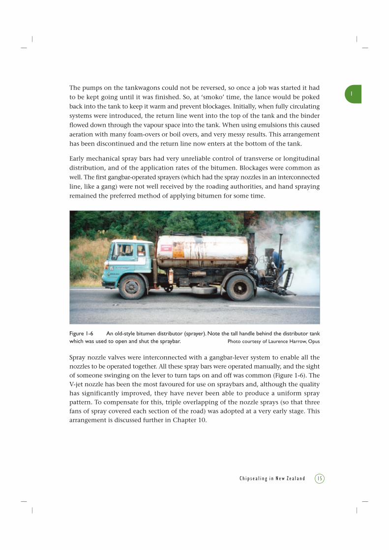
Figure 1-6 An old-style bitumen distributor (sprayer). Note the tall handle behind the distributor tankwhich was used to open and shut the spraybar. Photo courtesy of Laurence Harrow, Opus
1
15C h i p s e a l i n g i n N e w Z e a l a n d
The pumps on the tankwagons could not be reversed, so once a job was started it had
to be kept going until it was finished. So, at ‘smoko’ time, the lance would be poked
back into the tank to keep it warm and prevent blockages. Initially, when fully circulating
systems were introduced, the return line went into the top of the tank and the binder
flowed down through the vapour space into the tank. When using emulsions this caused
aeration with many foam-overs or boil overs, and very messy results. This arrangement
has been discontinued and the return line now enters at the bottom of the tank.
Early mechanical spray bars had very unreliable control of transverse or longitudinal
distribution, and of the application rates of the bitumen. Blockages were common as
well. The first gangbar-operated sprayers (which had the spray nozzles in an interconnected
line, like a gang) were not well received by the roading authorities, and hand spraying
remained the preferred method of applying bitumen for some time.
Spray nozzle valves were interconnected with a gangbar-lever system to enable all thenozzles to be operated together. All these spray bars were operated manually, and the sightof someone swinging on the lever to turn taps on and off was common (Figure 1-6). TheV-jet nozzle has been the most favoured for use on spraybars and, although the qualityhas significantly improved, they have never been able to produce a uniform spraypattern. To compensate for this, triple overlapping of the nozzle sprays (so that threefans of spray covered each section of the road) was adopted at a very early stage. Thisarrangement is discussed further in Chapter 10.

1
C h i p s e a l i n g i n N e w Z e a l a n d16
Dipping the tankThe task of dipping the tank had to be done to measure the volume of bitumen usedbefore and after a sealing job. It was also done regularly during a sequence of spray runsto determine the actual spray rate of bitumen that was being applied. It involvedclambering up to the top of the distributor tank and could be a hazardous job, especiallyin the poor light of a plant shed at the end of a long hard day’s work. There are talesof shortcuts like using a cigarette lighter to peer at the dipstick while holding it over anopened hatch (with the real possibility of an explosion, and not recommended in anyCodes of Practice)!
ThermostatsEarly thermostats used on tankers had wide temperature differentials and the differencebetween the cut-off and cut-in temperatures could be as high as 20°C. These had somerepercussions as in the following instance. To ensure the temperature would be rightfor a early morning start, one over-conscientious operator set the temperature 20°Chigher than the normal. When he arrived on the Monday morning, flames were lickingaround the top hatch of the tank.
Heating equipmentHeating equipment has undergone considerable changes since the tarpot days, butnonetheless can be lethal devices.
Flame tube heating – this is heating by direct firing into a burner tube located near thebottom of the tank. The quest for faster heating rates resulted in flame tubes beingequipped with burners that had a capacity greater than the rate at which the bitumencould transfer the heat throughout the tank. Flame-tube wall temperatures could reachdangerous levels, and the internal walls of the flame tube would be glowing red hot forsome considerable time after the heater was turned off. Spot heating of the tube wallswas another problem to watch for.
The main causes of tanker explosions and fires have been a consequence of these tubesbecoming exposed to the flammable vapours inside the tank, explained further inChapter 2.
Research work on flame-tube heating was initiated by the NZ PBCA2 in the mid-1990s,and maximum heating rates and temperatures (i.e. 350°C) for flame tube heaters wereestablished.
2 NZ PBCA (NZ Pavement & Bitumen Contractors’ Association) is now Roading New Zealand as from26/06/2004.

1
17C h i p s e a l i n g i n N e w Z e a l a n d
Heat transfer oil systems – these systems heat by circulating hot oil via a heating chamber,and then through a tube ‘nest’ immersed in the bitumen tank. Bulk storage installationscontinue to use this system but extra care is required if they are to be used in the blendingtanks used for cutback bitumen.
Electric elements – these were the preferred and safest option (and still are) for heatingbitumen and various types have been used. A low-voltage transformer supplies currentthrough elements comprising mild steel rods, such as reinforcing steel, mounted oninsulated supports located near the bottom of the tank. These are safe and reliableprovided that the heat rate of the rods is kept low.
Controlling sprayer road speedIn the early days of mechanical sprayers (Figure 1-7), another skill the driver neededwas to alter spray rates by altering road speed. The gearing systems of some trucks couldnot cope with the slow speeds needed for high application rates, and many clutches wereburnt out.
Road surfaces with varying textures called for additional skills of observation to achieveacceptable application rates. The overseer walked alongside the tanker observing theroad texture ahead of the sprayer and signalled the driver to slow or speed up as required.
Figure 1-7 A 1940s bitumen distributor and hand sprayer, vacuum-filled and pressure discharged, ondisplay at the property of John Matthews, Technix Group Ltd, New Plymouth.
Photo courtesy of John Matthews, Technix Group Ltd
1
C h i p s e a l i n g i n N e w Z e a l a n d18
Early calibration of sprayers and uniformity of transverse distribution were checked byplacing paint tins underneath each nozzle and measuring the amount collected over aselected time. A more sophisticated method was to run the sprayer over a set of 50 mm-wide absorbent pads to measure the variability in transverse distribution.
Fan-tail chip spreadersThese chip spreaders have fan-tailed shaped rear gates and were generally used on short-wheel-based trucks to allow the tray to be raised high enough in all situations (seeFrontispiece). As these trucks were operated in reverse, they were an occupational hazardfor the fan-tail operators who had to perform a number of dangerous tasks, e.g. walkingalongside the rear of the truck, sometimes on the driver’s blind side, and running in toput in dividing plates. Operators were likely to be injured if the driver of the reversingtruck could not see them.
Fan-tail spreaders were difficult to operate successfully and the driver had to be very skilful.Also they did not give uniform application, especially on corners. Windows or gaps in thesealing chip had to be spotted and covered by hand-spreading from the back of a truck.In addition to the spotting team, drag brooms were used as a means of redistributing theuneven chip layers. With the advent of roller spreaders in the mid-1960s, chip coverageimproved significantly. These days there is less need for drag brooming or spotting andthey are seldom used. Kinds of spreaders and rollers are covered in Chapter 10.
The Flaherty Chip Master spreader was imported from the United States in 1960 and,as this machine was driven forwards rather than reversed, both driver and operator wereable to see each other. It was safer, but as it was a single purpose machine it never gainedgeneral acceptance.
While purpose-built chip-spreading machines are used today, roller spreaders mountedon trucks are the predominant type.
Rollers
At first, 7 or 9 ton (7.11 or 9.14 tonnes) 3-wheel steel rollers were used (without ballastfor easy transport and to reduce crushing of the aggregate on the road). Over the years,rollers improved and new models were introduced, such as the 13-ton (13.2 tonnes)
rubber-tyred roller which required fewer passes. Now fewer passes are needed and the
chip is not crushed but kept at the design size required for the job.

1
19C h i p s e a l i n g i n N e w Z e a l a n d
1 . 7 Chang e s i n P r o c e du r e sAsset Maintenance
A problem with chipseal is that it is not permanent. Though relatively flexible, cracks
left untreated will let water in and increase the incidence of potholes and deformation.
Because wear and weathering require spot repairs and eventual resealing, a deliberate
maintenance regime and provision for resealing are needed in the longer term care of
a chipseal.
To keep track of the state of the roads and their needs for maintenance and resealing,
the database Road Assessment and Maintenance Management System or RAMM was
established in 1985. RAMM is an inventory of road assets and of their condition. Its
function is to use the inventory and condition to predict short-term treatment needs.
The RAMM Road Condition Rating Manual (known as the RAMM Rating Manual but now
out of print) was issued in 1988 by the then National Roads Board, and has been
administered by Transit New Zealand since 1989, and uses software supplied by CJN
Technologies (2004).
In 1994 the Minister of Transport, in consultation with the Minister of Finance, required
all local authorities to have in place a maintenance management system based on RAMM
no later than 30 June of that year. As a result, all Road Controlling Authorities (RCAs,
i.e. authorities responsible for roading within their jurisdictions) are now using RAMM.
From the mid-1990s, intelligent systems have been implemented in New Zealand that use
the RAMM inventory and condition information to predict long-term maintenance needs
when developing maintenance Forward Works Programmes (explained in Chapter 5).
dTIMS3 is the software now used for pavement deterioration modelling in New Zealand,
and its models are largely based on the World Bank HDM-III and HDM-4 models4. All
these systems are essential components of a Pavement Management System (PMS).
Bitumen Burns Card and Safety
Because bitumen burns require special treatment differing from that for burns caused by
other sources of heat, the yellow Bitumen Burns Card was developed by the roading
industry. It is to alert medical staff in rescue teams and hospitals to these special requirements
and to communicate directly with specialist Burns Units. It is illustrated in Chapter 2, in
which the importance of safety in the chipsealing industry is emphasised.
3 dTIMS – Deighton’s Total Infrastructure Management System.4 HDM-III – Highway Design and Maintenance Standards model, version III
HDM-4 – Highway Development and Management model, version 4
1
C h i p s e a l i n g i n N e w Z e a l a n d20
Training
Early training was in the field, on the job and by the boss, overseer or supervisor.
Generally it was minimal and learned by rote. Thus workers could become good operators
but did not necessarily understand what they were doing. When problems arose the
general rule was to get the boss onto them quickly. In addition technology was poor,
and crews worked in high temperatures and with flammable materials, so it was a dirty
hard dangerous job. High staff turnover was always a problem, meaning that training
was usually not adequate to cope with these hazards. For highly trained overseers and
staff however, a major source was the Ministry of Works.
Predecessors of Transit New Zealand
Since 1989, Transit New Zealand is the RCA responsible for the national State
Highway system. Its predecessors are various, and the brief family tree that follows
almost needs a genealogist to interpret (see also timeline on pages 4 & 5).
The Department of Roads was established in 1901, and then amalgamated with the
Public Works Department (PWD) in 1909, which had been in existence from 1870.
From 1924 the Main Highways Board (MHB) became responsible for state and
main highways, serviced by the PWD. In 1954 the MHB was replaced by the
National Roads Board (NRB). NRB had responsibility for state highways design,
construction and maintenance, and for the distribution of most central government
roading disbursements to RCAs. NRB was serviced by the Ministry of Works
(MOW) which had come into existence when the Ministry of Works Act was
passed in 1943. The PWD was merged with the MOW in 1948 and then ceased
to exist. Following some re-organisation in the late 1970s, the MOW was succeeded
by the Ministry of Works and Development (MWD).
The NRB and its Road Research Unit (RRU) continued until 1989 when the Transit
New Zealand Act was passed and Transit New Zealand came into existence.
Amendments to the Act were passed in 1991 and 1992, before a major amendment
in 1995 created Transfund (the funder of roads) and split it from Transit (the
provider of roads).
The latest change made to the family was in 2004, when Transfund and the Land
Transport Safety Authority were amalgamated to form the new Land Transport
New Zealand.
For a full history up to 1970, read By Design. A brief history of the Public Works
Department. Ministry of Works, 1870-1970 (Noonan 1975).

1
21C h i p s e a l i n g i n N e w Z e a l a n d
Today, training programmes leading to National Qualifications within the NZ
Qualifications Authority (NZQA) framework, such as NZ Certificate of Engineering, and
courses at the NZ Institute of Highway Technology (NZIHT) in New Plymouth, mean
more skilled staff can be trained and prepared to be career-oriented employees for
the industry.
Other highly qualified people, chemists and engineers can also find niches in chipseal
research. Research on the physical and chemical properties of chipseal components and
the chipsealing system ensures that producing a final chipseal surface is no longer an
art, but instead a controlled and consistent procedure that will deliver the desired results.
This book is about the various ways that those results can be obtained.
Hanson’s advocacy for scientific and rational research into roading is now a reality,
and this book aims to continue building on his vision.
1 . 8 R e f e r e n c e s
CJN Technologies. 2004. RAMM software. www.cjntech.co.nz
Hanson, F.M. 1935. Bituminous surface treatment of rural highways. Discussion on
bituminous surface treatment. The NZ Society of Civil Engineers Proceedings 1934-35, 21:
89-220.
Hanson, F.M. 1948. Relationship of metal depths and subgrade properties for modern
highway loads. Discussion. NZIE 1948 Proceedings XXXIV: 305-407.
Morgan, P., Mulder, A. 1995. The Shell Bitumen Industrial Handbook. Shell Bitumen,
Chertsey, Surrey, UK. 411pp.
National Roads Board (NRB). 1968. Manual of sealing and paving practice. Prepared for
Road Research Unit, National Roads Board, Wellington, New Zealand.
National Roads Board (NRB). 1974. Roads in New Zealand. NRB Information Leaflet
No. 2. 32pp.
National Roads Board (NRB). 1988. Road Assessment and Maintenance Management System
Road Condition Rating Manual.
Noonan, R.J. 1975. By Design. A brief history of the Public Works Department, Ministry of
Works, 1870-1970. AR Shearer, Government Printer, Wellington, New Zealand. 330pp.
NZ PBCA (NZ Pavement & Bitumen Contractors’ Association Inc.). 2000. The safe
handling of bituminous materials used in roading. Code of Practice BCA 9904. NZ PBCA
(now Roading New Zealand), PO Box 12-412, Wellington, New Zealand.
Transit New Zealand. 1995. Roading bitumens. TNZ M/1:1995 (previously NRB M/1).
Transit New Zealand. 2004. Specification for sealing chip. TNZ M/6:2004.
1
C h i p s e a l i n g i n N e w Z e a l a n d22