chapter nine interchanges - maine.gov · 9-1 december 2004 warrants chapter nine interchanges 9-1...
TRANSCRIPT

Volume I
- Highway Design Guide –
National Standards
December 2004
CHAPTER NINE
INTERCHANGES

9-i December 2004 INTERCHANGES
Chapter Nine TABLE OF CONTENTS Page 9-1 WARRANTS ................................................................................................................... 9-1 9-2 INTERCHANGE TYPES................................................................................................ 9-2
9-2.01 Three-Leg....................................................................................................... 9-2 9-2.02 Diamond......................................................................................................... 9-2 9-2.03 Cloverleafs ..................................................................................................... 9-5 9-2.04 Interchange Type Selection (Service Interchanges) ...................................... 9-6 9-2.05 Directional and Semi-Directional .................................................................. 9-8
9-3 FREEWAY/RAMP JUNCTIONS ................................................................................. 9-10
9-3.01 Exits ............................................................................................................. 9-10 9-3.02 Entrances...................................................................................................... 9-18
9-4 RAMP DESIGN............................................................................................................. 9-25
9-4.01 Design Speed ............................................................................................... 9-25 9-4.02 Cross Section ............................................................................................... 9-25 9-4.03 Horizontal Alignment .................................................................................. 9-26 9-4.04 Vertical Alignment ...................................................................................... 9-30 9-4.05 Roadside Safety ........................................................................................... 9-31
9-5 COLLECTOR - DISTRIBUTOR ROADS.................................................................... 9-32
9-1 December 2004 WARRANTS
Chapter Nine INTERCHANGES
9-1 WARRANTS An interchange is a system of interconnecting roadways in conjunction with one or more grade separations that provide for the movement of traffic between roadways on different levels. The following lists several general warrants for an interchange: 1. Design Designation. Once a controlled access facility has been designated on the major
road, an interchange may be warranted for a crossing road based on the anticipated demand for access to the minor road.
2. Traffic Volumes. An interchange may be warranted to accommodate the traffic volumes at
the selected level of service and the traffic distribution pattern of an at-grade intersection. 3. Road-User Benefits. An interchange may be warranted where the road user costs (e.g.,
travel time, accidents) are significantly reduced when compared to at-grade intersections. 4. Site Topography. The topography at some locations may allow an interchange at less cost
than an at-grade intersection. If an interchange is warranted for any of the listed reasons, interchange spacing is an additional consideration in the decision-making process. As a general rule, interchanges should be no closer than one mile apart in urban areas and two miles apart in rural areas. Closer interchange spacings may be acceptable if a special design can be implemented (e.g., collector-distributor roads) so that the freeway elements (e.g., weaving areas, freeway/ramp terminals) can operate at an acceptable level of service.

9-2 December 2004 INTERCHANGE TYPES 9-2 INTERCHANGE TYPES Each interchange must be designed to fit the individual site characteristics. The final design may be a minor or major modification of one of the basic types, or it may be a combination of two or more interchange types. In addition to interchange types, the following basic definitions apply to interchange designation: 1. Systems Interchanges. These are interchanges between two fully access-controlled
highways (freeways). 2. Service Interchanges. These are interchanges where one or both of the intersecting
highways is not a fully access-controlled facility. 9-2.01 Three-Leg Three-leg interchanges are also designated as T- or Y-interchanges. Figure 9-1 illustrates examples of three-leg interchanges with several methods of providing the turning movements. The trumpet type (A) provides three turning movements with direct or semi-direct ramps and one movement by a loop ramp. In general, the semi-direct ramp should favor the heavier left-turn movement and the loop the lighter volume. Where both left-turning movements are fairly heavy, the design in (C) should be used. A fully directional interchange (B) is appropriate when all turning volumes are heavy, or the intersection is between two access-controlled highways. 9-2.02 Diamond The diamond interchange is often the best choice where the intersecting road is not access controlled. Figure 9-2 illustrates a schematic of the diamond. Its advantages include: 1. Adequate sight distance can usually be provided, and the operational maneuvers are
normally uncomplicated. 2. Less right-of-way is required. 3. All exits from the mainline are made before reaching the structure. 4. Left-turning maneuvers require less travel distance

9-3 December 2004 INTERCHANGE TYPES
TYPICAL THREE-LEG INTERCHANGES
Figure 9-1

9-4 December 2004 INTERCHANGE TYPES
TYPICAL DIAMOND INTERCHANGE
Figure 9-2 5. The diamond interchange allows relatively easy modifications to provide greater ramp
capacity, if needed in the future.

9-5 December 2004 INTERCHANGE TYPES 6. Their common usage has resulted in a high degree of driver familiarity. The primary disadvantages of a diamond interchange are the potential operational problems with the two at-grade intersections at the minor road and the potential for wrong-way entry onto the ramps from the minor road. 9-2.03 Cloverleafs Cloverleaf interchanges are used at 4-leg intersections and employ loop ramps to accommodate left turn movements. Full cloverleaf interchanges are those with loops in all four quadrants; all others are partial cloverleafs. Where two access controlled and divided highways intersect, a full cloverleaf is the minimum type design that will suffice (Figure 9-3). However, these interchanges introduce several operational
FULL CLOVERLEAF INTERCHANGE
Figure 9-3 features such as the double exits and entrances from the mainline, the weaving between entering and exiting vehicles with the mainline traffic, and the lengthy travel time and distance for left-turning

9-6 December 2004 INTERCHANGE TYPES vehicles. Therefore, at high-volume freeway interchanges, a collector-distributor (C-D) road may be considered. See Section 9-5. Partial cloverleafs are appropriate where right-of-way restrictions preclude ramps in one or more quadrants. Figure 9-4 illustrates six examples of partial cloverleafs. In "A" and "B", both left-turn movements onto the major road are provided by loops, which is desirable. The other examples (C-F) illustrate two loops in opposite quadrants and loops in three quadrants. In these examples, the desirable feature is that no left-turn movements are made onto the major road. 9-2.04 Interchange Type Selection (Service Interchanges) At other than a freeway-to-freeway connection, the choice of interchange will be a full or partial cloverleaf or a diamond. The following should be considered when making the selection: 1. Cloverleafs require more right-of-way and are more expensive to construct than diamonds. 2. Full cloverleafs result in no 90-degree intersections, as do partial cloverleafs and diamonds. 3. Full cloverleafs and some partial cloverleaf arrangements result in weaving sections. 4. The loops in cloverleafs result in a greater travel distance for left-turning vehicles when
compared to diamonds. 5. All exit and entrance maneuvers at diamonds are executed before reaching the structure.
This is not true of cloverleafs, and the double exits may cause signing problems. 6. Ramps at diamond interchanges can be widened to increase capacity. Loop ramps,
regardless of width, almost always operate in a single line, therefore limiting capacity. 7. Pedestrian movements along cross streets are more difficult at cloverleaf interchanges. 8. Full cloverleafs are often considered more appropriate than diamonds when traffic
volumes are high. However, considering the general advantages of diamonds, the designer should investigate measures to increase the capacity of diamond interchanges such as preferential signal phasing and signal coordination on the minor road
PARTIAL CLOVERLEAF ARRANGEMENTS

9-7 December 2004 INTERCHANGE TYPES
Figure 9-4
9-2.05 Directional and Semi-Directional The following definitions apply to directional and semi-directional interchanges: 1. Directional Interchange. An interchange where one or more turning movements are
provided by direct connection. 2. Semi-Directional Interchange. An interchange where one or more left-turning movements
are provided by semi-direct connections, even if the minor left-turn movements are accommodated by loops, and where there are no directional ramps.
3. Fully Directional Interchange. An interchange where all turning movements are
accommodated by direct connections. The following definitions apply to directional and semi-directional ramps: 1. Direct Ramp Connection. A ramp that does not deviate greatly from the intended direction
of travel (as does a loop, for example). 2. Semi-Direct Ramp Connection. A ramp that is indirect in alignment yet more direct than
loops. Direct or semi-direct connections are used for heavy left-turn movements to reduce travel distance, increase speed and capacity, and eliminate weaving. These type connections allow an interchange to operate at a better level of service than is possible with loop ramps. Figure 9-5 illustrates three semi-directional and directional interchanges. Note that none of these designs has left-hand exits or entrances from the mainline, which is very desirable. Left-hand exits and entrances violate driver expectancy and should not be used, if practical. Directional or semi-directional interchanges are most often warranted in urban areas at freeway-to-freeway or freeway-to-arterial intersections. They require less right-of-way than cloverleaf interchanges. A fully directional interchange provides the highest possible capacity and level of service, but it is very costly to build because of the multiple-level structure required.

9-8 December 2004 INTERCHANGE TYPES
DIRECTIONAL INTERCHANGES

9-9 December 2004 INTERCHANGE TYPES
Figure 9-5
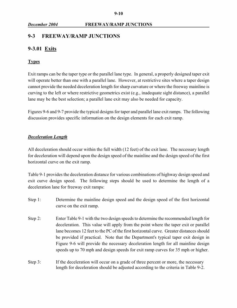
9-10 December 2004 FREEWAY/RAMP JUNCTIONS 9-3 FREEWAY/RAMP JUNCTIONS 9-3.01 Exits Types Exit ramps can be the taper type or the parallel lane type. In general, a properly designed taper exit will operate better than one with a parallel lane. However, at restrictive sites where a taper design cannot provide the needed deceleration length for sharp curvature or where the freeway mainline is curving to the left or where restrictive geometrics exist (e.g., inadequate sight distance), a parallel lane may be the best selection; a parallel lane exit may also be needed for capacity. Figures 9-6 and 9-7 provide the typical designs for taper and parallel lane exit ramps. The following discussion provides specific information on the design elements for each exit ramp. Deceleration Length All deceleration should occur within the full width (12 feet) of the exit lane. The necessary length for deceleration will depend upon the design speed of the mainline and the design speed of the first horizontal curve on the exit ramp. Table 9-1 provides the deceleration distance for various combinations of highway design speed and exit curve design speed. The following steps should be used to determine the length of a deceleration lane for freeway exit ramps: Step 1: Determine the mainline design speed and the design speed of the first horizontal
curve on the exit ramp. Step 2: Enter Table 9-1 with the two design speeds to determine the recommended length for
deceleration. This value will apply from the point where the taper exit or parallel lane becomes 12 feet to the PC of the first horizontal curve. Greater distances should be provided if practical. Note that the Department's typical taper exit design in Figure 9-6 will provide the necessary deceleration length for all mainline design speeds up to 70 mph and design speeds for exit ramp curves for 35 mph or higher.
Step 3: If the deceleration will occur on a grade of three percent or more, the necessary
length for deceleration should be adjusted according to the criteria in Table 9-2.

9-11 December 2004 FREEWAY/RAMP JUNCTIONS
TYPICAL TAPER EXIT RAMP
Figure 9-6
TY
PIC
AL
TA
PER
EX
IT R
AM
P
Figu
re 9
-6

9-12 December 2004 FREEWAY/RAMP JUNCTIONS
TYPICAL PARALLEL LANE EXIT RAMP
Figure 9-7
TY
PIC
AL
PA
RA
LL
EL
LA
NE
EX
IT R
AM
P
Figu
re 9
-7

9-13 December 2004 FREEWAY/RAMP JUNCTIONS
L = Deceleration Length (ft)
For Design Speed of First Horizontal Curve on Ramp (mph)
Major Highway
Design Speed (mph)
0
(Stop)
15
20
25
30
35
40
45
50
30
235
200
170
140
-
-
-
-
-
40
320
295
265
235
185
155
-
-
-
50
435
405
385
355
315
285
225
175
-
60
530
500
480
460
430
405
350
300
240
65
570
540
520
500
470
440
390
340
280
70
615
590
570
550
520
490
440
390
340
MINIMUM LENGTH FOR DECELERATION (Level Grade)
Table 9-1
Ratio of Deceleration Length on Grade to Length on Level
Direction of
Grade
< 3%
3% ≤ G < 5%
5% ≤ G < 7%
G ≥ 7%
Upgrade
1.0
0.9
0.8
0.7
Downgrade
1.0
1.2
1.35
1.5
Notes: 1. Table applies to all highway design speeds.
2. The "grade" in the table is the average grade over the distance used for measuring the length of the deceleration.
GRADE ADJUSTMENTS FOR DECELERATION
Table 9-2

9-14 December 2004 FREEWAY/RAMP JUNCTIONS Step 4: Where the first horizontal curve is compounded, determine the necessary distance
between the PC & PCC from Table 9-3. See Example 2.
Radius of Sharper Arc (R2) (ft)
Length of Adjoining Circular Arc (R1) (ft)*
100 150 200 250 300 400
> 500
60 70 90 120 140 180 200
* These criteria for R1 apply to a curve which precedes the "Radius of Arc (R2)" (R1 ≤ 2.0 R2). For a 3-centered curvature arrangement, the criteria also apply to the length of R2 which precedes R3 (R3 ≤ 2.0 R2).
LENGTHS OF COMPOUND CURVES (Freeway/Ramp Junctions) Table 9-3
* * * * * * * * * * Example 1 Given: Highway Mainline (Design Speed) - 70 mph
First Horizontal Curve on Ramp (Design Speed) - 40 mph Average Grade - 5% downgrade
Problem: Determine necessary length for deceleration. Solution: Table 9-1 yields a minimum deceleration length of 440 ft on the level. According to
Table 9-2, this should be increased by 1.35.

9-15 December 2004 FREEWAY/RAMP JUNCTIONS Therefore: L = (440) (1.35)
L = 594 ft
A 594-ft deceleration length should be provided from the point at which a taper exit becomes 12 feet or for the full width of the parallel lane to the PC of the first horizontal curve.
Example 2 Given: The first horizontal curve on an exit ramp is a 3-centered curvature arrangement with
the following radii:
R1 = 600 ft R2 = 300 ft R3 = 600 ft
Problem: Determine the minimum length of the arc R1 (from PC to PCC) to allow the vehicle
to decelerate from the design speed of R1 to the design speed of R2. Solution: Table 9-3 indicates that, if R2 = 300 ft, the preceding arc should be at least 140 ft to
allow safe deceleration. Therefore, the distance between the PC and PCC should be 140 ft or more. Note that, because R3 is flatter than R2, deceleration need not be considered in determining the length of arc from the PCC to PT. Figure 9-6 illustrates the 3-centered curvature arrangement.
* * * * * * * * * *
Sight Distance Decision sight distance should be available for drivers approaching an exit. This sight distance is particularly important for exit loops immediately beyond the structure. Vertical curvature or bridge piers can obstruct the exit points if not carefully designed. When measuring for adequate sight distance, the designer should use a 2.0-ft height of object and should use the gore nose as the point to where decision sight distance should be available. Section 4-1.02 discusses decision sight distance in more detail.
* * * * * * * * *

9-16 December 2004 FREEWAY/RAMP JUNCTIONS Example 3 Given: An exit loop is located just beyond a bridge which is on a crest vertical curve. The
algebraic difference (A) is 3% for the curve. The facility is a rural freeway with a design speed of 70 mph.
Problem: Determine the necessary length of the vertical curve to provide decision sight
distance (DSD) to the exit gore. Solution: Section 4-1.02 discusses DSD. Based on the DSD criteria and the given information,
the following elements will apply to the design of the crest vertical curve:
A = 3%
DSD = 1105 ft (direction change on a rural road at 70 mph)
Height of eye (h1) = 3.5 ft
Height of object (h2) = 2.0 ft
The equation for L for the crest vertical curve is:
Therefore, a crest vertical curve with a length of approximately 1700 ft should be provided.
* * * * * * * * * * Superelevation The superelevation at an exit ramp junction should be developed to properly transition the driver from the mainline to the curvature at the exit. The principles of superelevation for open highways,
)h2 + h2100()A(DSD = L 2
21
2
1697 = L
)(2)(2.0) + (2)(3.5)100()(3)(1105 = L 2
2

9-17 December 2004 FREEWAY/RAMP JUNCTIONS as discussed in Section 5-2.05, should be applied to the exit ramp junction design. The following specific superelevation criteria will apply: 1. Rate. emax =6.0%. For a given design speed and radius of curve, Table 5-6 will be used to
determine the superelevation rate for the first horizontal curve. 2. Transition Length. The minimum superelevation transition length from typical cross slope
(2.0%) to "e" will be 100 feet, regardless of the superelevation rate at the PC of the first horizontal curve. The 100-foot distance applies where the mainline is on a tangent or where the mainline is curving in the same direction as the ramp exit. Where the mainline is curving away from the ramp exit and is superelevated, a parallel deceleration lane should normally be used.
3. Distribution. Full superelevation should be reached at the first 50 foot station occurring a
minimum distance of 25 feet beyond the PC of the first horizontal curve. The beginning of the transition will occur at least 100 feet in advance of the station where full superelevation is reached.
Where compound curvature is used at the freeway/ramp exit, the design "e" (for the sharper curve) will be reached at the first 50-foot station occurring a minimum distance of 25 feet beyond the PCC.
4. Axis of Rotation. The axis of rotation will typically be about the line on the right edge of
travelway (i.e., the control edge profile line) of the exit ramp. The cross slope of the left and right shoulders will be adjusted during the superelevation transition such that the algebraic difference between the travelway slope and high-side shoulder slope will not exceed 8%.
Cross Slope Rollover The cross slope rollover is the algebraic difference between the slope of the through lane and the slope of the exit lane, when these two are adjacent to each other (i.e., before the gore begins). The maximum algebraic difference is 5 percent. Gore Area 1. Definition. The gore area is normally considered to be the paved triangular area between the
through lane and the exit lane, plus the graded area, which may extend a considerable distance downstream beyond the gore nose.

9-18 December 2004 FREEWAY/RAMP JUNCTIONS 2. Roadside Hazards. If practical, the area beyond the gore nose should be free of signs and
luminaire supports for approximately 300 feet beyond the gore nose. If supports must be present, they must be yielding or breakaway or shielded by guardrail or a crash cushion. (See Chapter Ten).
3. Cross Slope. The paved triangular gore area between the through lane and exit lane should
be safely traversable. If practical, this area should have a uniform slope at a rate which is intermediate between the slope of the through lane and the slope of the exit lane. However, if a drainage inlet is placed within the paved gore, this will not be practical and may, in fact, require two breaks in the cross slope. In this case, the break in pavement cross slope should not exceed 5 percent at any point.
9-3.02 Entrances Types Entrance ramps can be either the taper type or the parallel lane type. A taper entrance ramp requires that the entering vehicle accelerate to the merging speed while still on the ramp proper. The taper type entrance should normally be used at sites where: 1. merging volumes are relatively low (i.e., the volumes are well below the capacity of the
freeway/ramp junction (LOS B or better)); 2. the entering driver has considerable sight distance (preferably decision sight distance based
on the ramp design speed) to see upstream to sight the mainline traffic; and 3. sufficient distance is available for vehicular acceleration. If any of these criteria are not met, the designer should seriously consider the parallel lane type entrance ramp. Figures 9-8 and 9-9 present typical designs for taper and parallel lane entrance ramps. The following discussion provides specific information on the design elements for each ramp.

9-19 December 2004 FREEWAY/RAMP JUNCTIONS Acceleration Length Table 9-4 provides the acceleration distance for various combinations of entrance curve design speed and highway design speed. These lengths apply to the full width (12 feet) of the entrance lane; taper lengths are in addition to these values. The following steps should be used to determine the acceleration length for freeway entrance ramps: Step 1: Determine the mainline design speed and the design speed of the last horizontal curve on
the ramp. Step 2: Enter Table 9-4 with the two design speeds to determine the recommended length for
acceleration. This value will apply from the PT of the last horizontal curve to the end of where the acceleration lane is at least 12-feet wide.
Step 3: If the acceleration will occur on a grade of three percent or more, the necessary length
for acceleration should be adjusted according to the criteria in Table 9-5. Step 4: The values from Tables 9-4 and 9-5 provide sufficient distance for vehicular
acceleration; they may not safely allow a vehicle to merge into the mainline if traffic volumes are high. Where the mainline and ramp will carry traffic volumes approaching the design capacity of the freeway/ramp junction, the acceleration lane should be extended by 200 feet or more to provide a greater opportunity for merging.
Step 5: Where the last horizontal curve on the ramp is compounded, determine the necessary
distance between the PT and PCC from Table 9-3.
* * * * * * * * * * Example 4 Given: Highway Mainline Design Speed - 70 mph
Design Speed of Last Horizontal Curve - 40 mph Average Grade - 5% upgrade
TYPICAL TAPER ENTRANCE RAMP

9-20 December 2004 FREEWAY/RAMP JUNCTIONS
Figure 9-8

9-21 December 2004 FREEWAY/RAMP JUNCTIONS
TYPICAL PARALLEL LANE ENTRANCE RAMP
Figure 9-9
TY
PIC
AL
PA
RA
LL
EL
LA
NE
EN
TR
AN
CE
RA
MP
Fi
gure
9-9

9-22 December 2004 FREEWAY/RAMP JUNCTIONS
L = Acceleration Length (ft)
For Design Speed of Last Horizontal Curve on Ramp (mph)
Major Highway
Design Speed (mph)
0
(Stop)
15
20
25
30
35
40
45
50
30
180
140
-
-
-
-
-
-
-
40
360
300
160
210
120 -
-
-
-
50
720
660
610
550
450
350
130 -
-
60
1200
1140
1100
1020
910
800
550
420
180 70 1620 1560 1520 1420 1350 1230 1000 820 580
LENGTH FOR ACCELERATION (Level Grade)
Table 9-4
Problem: Determine necessary length for acceleration. Solution: Table 9-4 yields an acceleration length of 1000 ft on the level.
According to Table 9-5, this should be increased by 2.6.
Therefore: L = (1000) (2.6) L = 2600 ft
A 2600-ft acceleration length should be provided from the PT of the last horizontal curve to the end of where a 12-ft lane is provided.
* * * * * * * * * *
Sight Distance Decision sight distance should be provided for drivers on the mainline approaching an entrance terminal. They need sufficient distance to see the merging traffic so they can adjust their speed or change lanes to allow the merging traffic to enter the freeway. Likewise, drivers on the entrance ramp need to see a sufficient distance upstream from the entrance to locate gaps in the traffic stream for merging.

9-23 December 2004 FREEWAY/RAMP JUNCTIONS
Ratio of Acceleration Length on Grade to Acceleration Length on Level
Design Speed of Ramp Curve (mph)
Design Speed of Highway
(mph)
20
30
40
50
All Speeds
3% ≤ G ≤ 4% (Upgrade)
3% ≤ G ≤ 4% (Downgrade)
40
1.3
1.3
--
--
0.7
50
1.3
1.4
1.4
--
0.65
60
1.4
1.5
1.5
1.6
0.6
70
1.5
1.6
1.7
1.8
0.6
G > 4% (Upgrade)
G > 4% (Downgrade)
40
1.5
1.5
--
--
0.6
50
1.5
1.7
1.9
--
0.55
60
1.7
1.9
2.2
2.5
0.5
70
2.0
2.2
2.6
3.0
0.5
Notes: 1. No adjustment is needed on grades less than 3%.
2. The "grade" in the table is the average grade measured over the distance for which the acceleration length applies.
GRADE ADJUSTMENTS FOR ACCELERATION
Table 9-5

9-24 December 2004 FREEWAY/RAMP JUNCTIONS For application, drivers on the mainline should have decision sight distance available to the gore nose assuming a 0-foot height of object. Drivers on the ramp should have decision sight distance (based on the ramp design speed) available from the gore nose upstream assuming a 3.75-foot height of object. Section 4-1.02 discusses decision sight distance in more detail. Superelevation The ramp superelevation should be gradually transitioned to meet the normal cross slope of the mainline. The principles of superelevation for open highways, as discussed in Section 5-2.05, should be applied to the entrance design. The following criteria should be used: 1. Rate. emax = 6.0%. For a given design speed and radius of curve, Table 5-6 will be used to
determine the superelevation rate for the last horizontal curve on the ramp before the freeway/ramp junction.
2. Transition Length. The minimum superelevation transition length from "e" to the normal
cross slope of the through travel lane will be 100 feet. This distance applies where the mainline is on a tangent or where the mainline is curving in the same direction as the ramp entrance. Where the mainline is curving away from the ramp entrance and is superelevated, a parallel acceleration lane should normally be used.
3. Distribution. Full superelevation should end at the last 50-ft station occurring a minimum
distance of 25 feet before the PT of the last horizontal curve on the ramp. The end of the transition will occur at least 100 feet beyond the station where full superelevation ends.
Where compound curvature is used on the ramp before the freeway/ramp entrance, the design "e" (for the sharper curve) will end at the last 50-ft station occurring a minimum distance of 25 feet before the PCC at the last horizontal curve.
4. Axis of Rotation. The axis of rotation will typically be about the line on the right edge of
travelway (i.e., the control edge profile line) of the entrance ramp. The cross slope of the left and right shoulders will be adjusted during the superelevation transition such that the algebraic difference between the travelway slope and high-side shoulder slope will not exceed 8%.
Cross Slope Rollover The maximum algebraic difference between the slopes of the entrance lane and through lane is 5 percent, when these two lanes are adjacent to each other.

9-25 December 2004 RAMP DESIGN 9-4 RAMP DESIGN 9-4.01 Design Speed Table 9-6 provides the acceptable ranges of ramp design speed as compared to the design speed on the highway mainline. These design speeds apply to the ramp proper and not to the freeway/ramp junction. For exit ramps, the ramp proper begins 100 feet beyond the gore nose; for entrance ramps, the ramp proper ends 100 feet before the gore nose. If the two intersecting mainlines have different design speeds, the higher of the two should control. However, the ramp design speed may vary, the portion of the ramp nearer the lower-speed highway being designed for the lowest speed. In general, the higher range of design speeds should apply to directional ramps, such as at diamond and full directional interchanges. The low end of the range should apply to loop ramps and to ramps that terminate with stop control at the minor road intersection. The designer should note that loops with design speeds above 30 mph require extremely large areas and greatly increase the travel distance for vehicles. If a ramp will be terminated at an at-grade intersection with stop or signal control, the design speeds in the table will not apply to the ramp portion near the intersection.
Highway Design Speed (mph) 50 55 60 65 70
Ramp Design Speed (mph)
High Range
45
50
50
55
60
Low Range
25
25
30
30
35
RAMP DESIGN SPEEDS
Table 9-6 9-4.02 Cross Section 1. Width. Widths for one-lane ramps are typically 26 feet from pavement edge to pavement
edge. This includes a 14-foot travel lane and combined left and right shoulder widths of 12 feet. For pavement striping, this is normally distributed as a 4-foot left shoulder and an 8-foot right shoulder.
9-26 December 2004 RAMP DESIGN
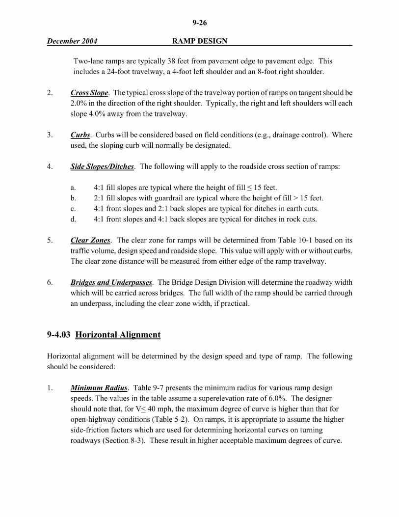
Two-lane ramps are typically 38 feet from pavement edge to pavement edge. This includes a 24-foot travelway, a 4-foot left shoulder and an 8-foot right shoulder.
2. Cross Slope. The typical cross slope of the travelway portion of ramps on tangent should be 2.0% in the direction of the right shoulder. Typically, the right and left shoulders will each slope 4.0% away from the travelway.
3. Curbs. Curbs will be considered based on field conditions (e.g., drainage control). Where
used, the sloping curb will normally be designated. 4. Side Slopes/Ditches. The following will apply to the roadside cross section of ramps:
a. 4:1 fill slopes are typical where the height of fill ≤ 15 feet. b. 2:1 fill slopes with guardrail are typical where the height of fill > 15 feet. c. 4:1 front slopes and 2:1 back slopes are typical for ditches in earth cuts. d. 4:1 front slopes and 4:1 back slopes are typical for ditches in rock cuts.
5. Clear Zones. The clear zone for ramps will be determined from Table 10-1 based on its
traffic volume, design speed and roadside slope. This value will apply with or without curbs. The clear zone distance will be measured from either edge of the ramp travelway.
6. Bridges and Underpasses. The Bridge Design Division will determine the roadway width
which will be carried across bridges. The full width of the ramp should be carried through an underpass, including the clear zone width, if practical.
9-4.03 Horizontal Alignment Horizontal alignment will be determined by the design speed and type of ramp. The following should be considered: 1. Minimum Radius. Table 9-7 presents the minimum radius for various ramp design
speeds. The values in the table assume a superelevation rate of 6.0%. The designer should note that, for V< 40 mph, the maximum degree of curve is higher than that for open-highway conditions (Table 5-2). On ramps, it is appropriate to assume the higher side-friction factors which are used for determining horizontal curves on turning roadways (Section 8-3). These result in higher acceptable maximum degrees of curve.

9-27 December 2004 RAMP DESIGN
Design Speed (mph)
Maximum Degree Of Curve
Minimum Radius (ft)
25 30 35 40 45 50 55 60
38°25°18°13°10°6°5°4°
15′ 00′ 30′ 15′ 30′ 45′ 15′ 15′
150 230 310 430 540 835 1065 1340
Note: e = 6.0%.
MINIMUM RADII ON RAMPS
Table 9-7
2. Compound Curves. When compound curves are used on the ramp proper, the radius of the flatter circular arc (R1) desirably will not be more than 50 percent greater than the radius of the sharper circular arc (R2). In other words, R1 is less than or equal to 1.5 R2. It is acceptable for R1 to be less than or equal to 2.0 R2.
For compound curves on ramps, the designer should also ensure that the length of successive circular arcs meet the criteria in Table 9-8. See Example 5.
Length of Adjoining Circular Arc (R1) (ft)*
Radius of Sharper
Arc (R2) (ft)
Minimum
Desirable
100 150 200 250 300 400 ≥500
40 50 60 80 100 120 140
60 70 90 120 140 180 200
* These criteria for R1 apply to a curve which precedes the "Radius of Arc (R2)" (R1 ≤ 2.0 R2). For a 3-
centered curvature arrangement, the criteria also apply to the length of R2 which precedes R3 (R3 ≤ 2.0 R2).
LENGTHS OF COMPOUND CURVES (Ramp Proper)
Table 9-8

9-28 December 2004 RAMP DESIGN 3. Stationing. The stationing on the ramp must be in the same direction as the stationing on the
highway mainline. 4. Superelevation. The following applies:
a. The maximum superelevation rate is 6.0%.
b. Table 9-9 presents the criteria for superelevation transition length for ramp curves.
c. For a one-lane ramp, all curves should have full superelevation from the first 50-foot station occurring a minimum distance of 25 feet after the PC to the last 50-foot station occurring a minimum distance of 25 feet before the PT. For a two-lane ramp, all curves should have full superelevation from the first 100-foot station occurring a minimum distance of 50 feet after the PC to the last 100-foot station occurring a minimum distance of 50 feet before the PT.
Length of Transition (LT)(ft)
Ramp Design Speed (mph)
Change in Cross Slope*
One-Lane Ramp (14-ft Travelway)
Two-Lane Ramp (24-ft Travelway)
V ≤ 40
4.0%
6.0%
8.0%
100 (minimum) 150 (desirable) 100 (minimum) 200 (desirable) 150 (minimum)
150 (desirable) 100 (minimum) 250 (desirable) 150 (minimum) 350 (desirable) 200 (minimum)
V > 40
All
250
400
* Change in cross slope is the algebraic difference between the normal cross slope of the travelway portion of the
ramp on the tangent and the cross slope of the travelway on the fully superelevated section. For example, if the normal cross slope is 2.0% and the ramp curve is superelevated at 4.0%, the change in cross slope is 6.0%.
SUPERELEVATION TRANSITION LENGTH (Ramps)
Table 9-9

9-29 December 2004 RAMP DESIGN
For compound curvature on the ramp proper, the design "e" (for the sharper curve) should be reached at the first 50-foot station occurring a minimum distance of 25 feet beyond the PCC.
d. Consecutive curves on ramps may provide deflections in opposite directions and,
therefore, are considered reverse curves. Desirably, the reverse curves will be designed with a 100-foot tangent section between the PT and PC. At a minimum, where the PT and PC are coincident (i.e., the tangent length is zero), the design will provide a level cross section.
e. The axis of rotation will typically be about a line on the right edge of travelway (i.e.,
the control edge profile line). This applies to curves in both the left and right directions and applies regardless of the pavement markings on the ramp. The cross slopes of the left and right shoulders will be adjusted during the superelevation transition such that the algebraic difference between the travelway slope and high-side shoulder slope will not exceed 8.0%.
f. The designer should not superelevate curves on ramps such that the design "e" is
maintained on the curve for a very short distance. As a general rule, the minimum distance for "e" should be 100-foot.
g. If the ramp will be terminated at an at-grade intersection with stop or signal control,
it is not appropriate to fully superelevate curves near the terminal. 5. Sight Distance. Section 5-2.06 describes how to determine the middle ordinate to provide
stopping sight distance at horizontal curves.
* * * * * * * * * * Example 5 Given: A horizontal curve on an exit ramp is a 3-centered curvature arrangement with the
following radii:
R1 = 500 ft R2 = 250 ft R3 = 500 ft

9-30 December 2004 RAMP DESIGN Problem: Determine the minimum length of the arc R1 (from PC to PCC) to safely allow the
vehicle to decelerate from the design speed of R1 to the design speed of R2. Solution: Table 9-8 indicates that, if R2 = 250 ft, the preceding arc should be at least 80 ft to allow
safe deceleration. Therefore, the distance between the PC & PCC should be 80 ft or more. Note that, because R3 is flatter than R2, deceleration need not be considered in determining the length of arc from the PCC to PT. Figure 9-6 illustrates a 3-centered curvature arrangement.
* * * * * * * * * *
9-4.04 Vertical Alignment Recommended values of limiting gradient are provided in Table 9-10, but for any one ramp the selected gradient is dependent upon a number of factors. These factors include the following: 1. The finished profile grade line is the right edge of the ramp travelway (i.e., the control edge). 2. The steepest gradients should be designed for the center part of the ramp. Landing areas or
storage platforms at at-grade intersections should be as flat as practical. 3. Downgrades on ramps should follow the same guidelines as upgrades. They may, however,
safely exceed these values by 2 percent, with 8 percent considered a recommended maximum.
4. Practical ramp gradients and lengths can be significantly impacted by the angle of
intersection between the two highways and the grade on the two mainlines.
Ramp Design Speed
(mph)
20
30
40
50
Maximum Grade (% Range)
6-8
5-7
4-6
3-5
Note: If practical, a maximum grade of 5% should be used.
RAMP GRADIENT GUIDELINES
Table 9-10

9-31 December 2004 RAMP DESIGN 5. The minimum longitudinal gradient will be as follows:
a. rural - 0.25% desirable; 0% minimum b. urban (uncurbed) - 0.25% desirable; 0% minimum c. urban (curbed) - 0.5% desirable; 0.25% minimum
Stopping sight distance based on the ramp design speed will be the minimum design for crest and sag vertical curves on ramps. See Table 9-11 for specific criteria. 9-4.05 Roadside Safety The criteria in Chapter Ten (e.g., clear zones, barrier warrants) will apply to the roadside safety design of interchange ramps. One special consideration is the warrants for a median barrier between adjacent on/off ramps, which will be determined on a case-by-case basis. This situation typically occurs at full and partial cloverleaf interchanges. At a minimum, raised islands will be used to separate traffic at these locations. Normally, sloping curbs will be used for the raised islands.
Ramp Design Speed (mph)
Stopping Sight
Distance (ft)
20 25 30 35 40 45 50 55 60
115 155 200 250 305 360 425 495 570
STOPPING SIGHT DISTANCE ON RAMPS
Table 9-11

9-32 December 2004 COLLECTOR-DISTRIBUTOR ROADS 9-5 COLLECTOR - DISTRIBUTOR ROADS Collector-distributor (C-D) roads are sometimes provided within an interchange to improve its operational characteristics. C-D roads will: 1. remove weaving maneuvers from the mainline, and 2. provide single exits and entrances from the mainline. C-D roads are most often warranted when traffic volumes are so high that the interchange without them cannot operate at an acceptable level of service, especially in weaving sections. They are particularly advantageous at full cloverleaf interchanges where the weaving between the ramp/mainline traffic can be very difficult. Figure 9-10 illustrates a schematic of a C-D within a full cloverleaf interchange. C-D roads may be one or two lanes, depending upon the traffic volumes and weaving conditions. The design speed should be the same as the mainline, but not more than 10 mph below the mainline. The separation between the C-D road and mainline should be as wide as practical, but not less than that required to provide the applicable shoulder widths and, if warranted, a longitudinal barrier between the two.
FULL CLOVERLEAF INTERCHANGE (With Collector-Distributor Road)
Figure 9-10