chapter · pdf filechapter no. title page no. ... 1.6 castigliano’s first theorem second...
TRANSCRIPT

ChapterNo.
Title PageNo.
1 ENERGY PRINCIPLES 1
1.1 Strain Energy 1
1.2 Proof Stress 1
1.3 Resilience 2
1.4 Proof Resilience 2
1.5 Modulus Of Resilience 2
1.6 Castigliano’s first theorem second Theorem. 3
1.7 Principle Of Virtual Work 13
1.8 Strain Energy Stored in a Rod of Length L and Axial RigidityAE To an Axial Force P
13
1.9 State the Various Methods for Computing the Joint Deflectionof a Perfect Frame
13
1.10 State the Deflection of the Joint Due To Linear Deformation 13
1.11 The Deflection of Joint Due to Temperature Variation 14
1.12 State the Deflection of a Joint Due to Lack of Fit 14
1.13 State the Difference Between Unit Load and Strain EnergyMethod in the Determination of Structures.
27
1.14 State the Assumptions Made in the Unit Load Method 27
2 INDETERMINATE BMEAS 29
2.1 Statically Indeterminate Beams 29
2.2 State the Degree Of Indeterminacy in Propped Cantilever 29
2.3 State the Degree Of Indeterminacy in A Fixed Beam 29
2.4 State the Degree Of Indeterminacy in The Given Beam 29
2.5 State the Degree Of Indeterminacy in The Given Beam 30
2.6 State the Methods Available for Analyzing StaticallyIndeterminate Structures
30
2.7 Write the Expression Fixed End Moments and Deflection for aFixed Beam Carrying Point Load at Centre
30
2.8 Write the Expression Fixed End Moments and Deflection for aFixed Beam Carrying Eccentric Point Load
30
2.9 Write the Expression Fixed End Moments for a Fixed Due ToSinking of Support
30
2.10 State the Theorem of Three Moments 34
2.11 Effect Of Settlement Of Supports In A Continuous Beam 35
3 COLUMNS 52
3.1 Columns 52
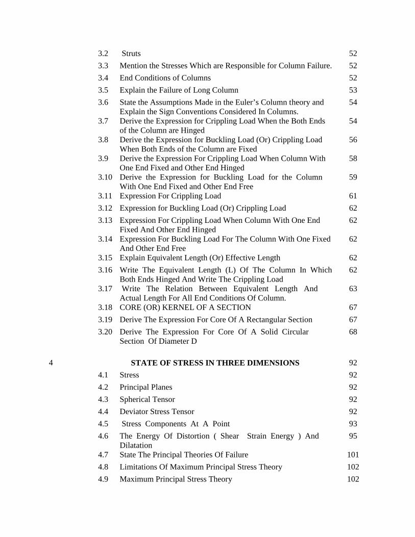
3.2 Struts 52
3.3 Mention the Stresses Which are Responsible for Column Failure. 52
3.4 End Conditions of Columns 52
3.5 Explain the Failure of Long Column 53
3.6 State the Assumptions Made in the Euler’s Column theory andExplain the Sign Conventions Considered In Columns.
54
3.7 Derive the Expression for Crippling Load When the Both Endsof the Column are Hinged
54
3.8 Derive the Expression for Buckling Load (Or) Crippling LoadWhen Both Ends of the Column are Fixed
56
3.9 Derive the Expression For Crippling Load When Column WithOne End Fixed and Other End Hinged
58
3.10 Derive the Expression for Buckling Load for the ColumnWith One End Fixed and Other End Free
59
3.11 Expression For Crippling Load 61
3.12 Expression for Buckling Load (Or) Crippling Load 62
3.13 Expression For Crippling Load When Column With One EndFixed And Other End Hinged
62
3.14 Expression For Buckling Load For The Column With One FixedAnd Other End Free
62
3.15 Explain Equivalent Length (Or) Effective Length 62
3.16 Write The Equivalent Length (L) Of The Column In WhichBoth Ends Hinged And Write The Crippling Load
62
3.17 Write The Relation Between Equivalent Length AndActual Length For All End Conditions Of Column.
63
3.18 CORE (OR) KERNEL OF A SECTION 67
3.19 Derive The Expression For Core Of A Rectangular Section 67
3.20 Derive The Expression For Core Of A Solid CircularSection Of Diameter D
68
4 STATE OF STRESS IN THREE DIMENSIONS 92
4.1 Stress 92
4.2 Principal Planes 92
4.3 Spherical Tensor 92
4.4 Deviator Stress Tensor 92
4.5 Stress Components At A Point 93
4.6 The Energy Of Distortion ( Shear Strain Energy ) AndDilatation
95
4.7 State The Principal Theories Of Failure 101
4.8 Limitations Of Maximum Principal Stress Theory 102
4.9 Maximum Principal Stress Theory 102

4.10 Maximum Shear Stress Theory 102
4.11 Limitations Of Maximum Shear Stress Theory 102
4.12 Shear Strain Energy Theory 102
4.13 Limitations Of Distortion Energy Theory 102
4.14 Maximum Principal Strain Theory 102
4.15 Limitations In Maximum Principal Strain Theory 102
4.16 Stress Tensor In Cartesian Components 102
4.17 Three Stress Invariants 103
4.18 Two Types Of Strain Energy 104
4.19 The Maximum Principal Stress 104
4.20 Explain The Maximum Shear Stress (Or) Stress DifferenceTheory
105
4.21 Explain The Shear Strain Energy Theory 106
4.22 Explain The Maximum Principal Strain Theory 107
4.23 Explain The Strain Energy Theory 109
4.24 Theories Of Failure 110
5 ADVANCED TOPICS IN BENDING OF BEAMS 119
5.1 Unsymmetrical Bending 119
5.2 State The Two Reasons For Unsymmetrical Bending 119
5.3 Shear Centre 119
5.4 Write The Shear Centre Equation For Channel Section 119
5.5 Write The Shear Centre Equation For Unsymmetrical I Section 120
5.6 Derive The Equation Of Shear Centre For Channel Section 120
5.7 Derive The Equation Of Shear Center For Unequa-Lsei Ction 121
5.8 Derive The Stresses In Curved Bars Us Ing Winkl–ErbachTheory
122
5.9 State The Parallel Axes And Principal Moment Of Inertia 135
5.10 Stress Concentration 135
5.11 Stress Concentration Factor 135
5.12 Fatigue Stress Concentration Factor 135
5.13 Shear Flow 135
5.14 Explain The Position Of Shear Centre In Various Sections 136
5.15 State The Principles Involved In Locating The Shear Centre 136
5.16 State The Stresses Due To Unsymmetrical Bending 136
5.17 Fatigue 136
5.18 Types Of Fatigue Stress 136

5.19 State The Reasons For Stress Concentration 137
5.20 Creep 137

CE6402 STRENGTH OF MATERIALS LT P C3 1 0 4
OBJECTIVES: To know the method of finding slope and deflection of beams and trusses using energy
theorems and to know the concept of analysing indeterminate beam. To estimate the load carrying capacity of columns, stresses due to unsymmetrical bending
and various theories for failure of material.
UNIT I ENERGY PRINCIPLES 9Strain energy and strain energy density – strain energy due to axial load, shear, flexure andtorsion – Castigliano‟s theorems – Maxwell‟s reciprocal theorems - Principle of virtual work –application of energy theorems for computing deflections in beams and trusses - Williot Mohr'sDiagram.
UNIT II INDETERMINATE BEAMS 9Concept of Analysis - Propped cantilever and fixed beams-fixed end moments and reactions –Theorem of three moments – analysis of continuous beams – shear force and bending momentdiagrams.
UNIT III COLUMNS AND CYLINDER 9Eulers theory of long columns – critical loads for prismatic columns with different end conditions;Rankine-Gordon formula for eccentrically loaded columns – Eccentrically loaded short columns –middle third rule – core section – Thick cylinders – Compound cylinders.
UNIT IV STATE OF STRESS IN THREE DIMENSIONS 9Determination of principal stresses and principal planes – Volumetric strain –Theories of failure –Principal stress - Principal strain – shear stress – Strain energy and distortion energy theories –application in analysis of stress, load carrying capacity.
UNIT V ADVANCED TOPICS IN BENDING OF BEAMS 9Unsymmetrical bending of beams of symmetrical and unsymmetrical sections – Shear Centre -curved beams –Winkler Bach formula.
TOTAL (L:45+T:15): 60 PERIODSOUTCOMES:
Students will have through knowledge in analysis of indeterminate beams and use ofenergy method for estimating the slope and deflections of beams and trusses.
They will be in a position to assess the behaviour of columns, beams and failure ofmaterials.
TEXT BOOKS:
1. Rajput R.K. "Strength of Materials (Mechanics of Solids)", S.Chand & company Ltd., NewDelhi, 2010.
2. Egor P Popov, “Engineering Mechanics of Solids”, 2nd edition, PHI Learning Pvt. Ltd., NewDelhi, 2012.
REFERENCES:
1. Kazimi S.M.A, “Solid Mechanics”, Tata McGraw-Hill Publishing Co., New Delhi, 2003.
2. William A .Nash, “Theory and Problems of Strength of Materials”, Schaum‟s OutlineSeries,Tata McGraw Hill Publishing company, 2007.
3. Punmia B.C."Theory of Structures" (SMTS) Vol 1&II, Laxmi Publishing Pvt Ltd, New Delhi2004.
4. Rattan.S.S., "Strength of Materials", Tata McGraw Hill Education Pvt. Ltd., New Delhi,2011.

CHAPTER - I
Strain energy and strain energy density- strain energy in traction, shear in flexure
and torsion- Castigliano’s theorem – Principle of virtual work – application of energy
theorems for computing deflections in beams and trusses – Maxwell’s reciprocal theorem.
Whenever a body is strained, the energy is absorbed in the body. The energy which is
absorbed in the body due to straining effect is known as strain energy. The strain energy stored in the
body is equal to the work done by the applied load in stretching the body.
The stress induced in an elastic body when it possesses maximum strain energy is termed as
its proof stress.
Derive the expression for strain energy in Linear Elastic Systems for the following cases. (i)
Axial loading (ii) Flexural Loading (moment (or) couple)
(i)Axial Loading
Let us consider a straight bar of Length L, having uniform cross- sectional area A. If an axial
load P is applied gradually, and if the bar undergoes a deformation ∆, the work done, stored
as strain energy (U) in the body, will be equal to average force (1/2 P) multiplied by the
deformation ∆.
Thus U = ½ P. ∆ But ∆ = PL / AE
U = ½ P. PL/AE = P2 L / 2AE ---------- (i)
If, however the bar has variable area of cross section, consider a small of length dx and area
of cross section Ax. The strain energy dU stored in this small element of length dx will be,
from equation (i)
P2 dx
dU = ---------
2Ax E
The total strain energy U can be obtained by integrating the above expression over the length
of the bar.
U = EA
dxP
x
L
2
2
0
ENERGY PRINCIPLES
1.2 PROOF STRESS
1.1 STRAIN ENERGY
CE 6402 STRENGTH OF MATERIALS
SCE 1 DEPARTMENT OF CIVIL ENGINEERING

M
1.5MODULUS OF RESILIENCE
1.4 PROOF RESILIENCE
(ii) Flexural Loading (Moment or couple )
Let us now consider a member of length L subjected to uniform bending moment M.
Consider an element of length dx and let di be the change in the slope of the element due to
applied moment M. If M is applied gradually, the strain energy stored in the small element will
be
dU = ½ Mdi
But
di d
------ = ----- (dy/dx) = d2y/d
2x = M/EI
dx dx
M
di = ------- dx
EI
Hence dU = ½ M (M/EI) dx
= (M2/2EI) dx
Integrating
U = L
EI
dx
0
2
2
The resilience is defined as the capacity of a strained body for doing work on the removal of
the straining force. The total strain energy stored in a body is commonly known as resilience.
The proof resilience is defined as the quantity of strain energy stored in a body when strained
up to elastic limit. The maximum strain energy stored in a body is known as proof resilience.
It is defined as the proof resilience of a material per unit volume.
Proof resilience
Modulus of resilience = -------------------
Volume of the body
Two methods for analyzing the statically indeterminate structures.
1.3 RESILIENCE
CE 6402 STRENGTH OF MATERIALS
SCE 2 DEPARTMENT OF CIVIL ENGINEERING

1.6 Castigliano’s first theorem second Theorem.
a. Displacement method (equilibrium method (or) stiffness coefficient
method
b.Force method (compatibility method (or) flexibility coefficient method)
First Theorem.
It states that the deflection caused by any external force is equal to the partial derivative of the
strain energy with respect to that force.
Second Theorem
It states that “If U is the total strain energy stored up in a frame work in equilibrium under an
external force; its magnitude is always a minimum.
Castigliano’s first theorem:
It states that the deflection caused by any external force is equal to the partial derivative
of the strain energy with respect to that force. A generalized statement of the theorem is as
follows:
“ If there is any elastic system in equilibrium under the action of a set of a forces
W1 , W2, W3 ………….Wn and corresponding displacements δ1 , δ2, δ3…………. δn and a set
of moments M1 , M2, M3………Mn and corresponding rotations Φ1 , Φ2, Φ3,…….. Φn , then
the partial derivative of the total strain energy U with respect to any one of the forces or
moments taken individually would yield its corresponding displacements in its direction of
actions.”
Expressed mathematically,
1
1
W
U ------------- (i)
1
1
M
U ------------- (ii)
Proof:
Consider an elastic body as show in fig subjected to loads W1, W2, W3 ………etc.
each applied independently. Let the body be supported at A, B etc. The reactions RA ,RB etc
do not work while the body deforms because the hinge reaction is fixed and cannot move
(and therefore the work done is zero) and the roller reaction is perpendicular to the
displacements of the roller. Assuming that the material follows the Hooke‟s law, the
displacements of the points of loading will be linear functions of the loads and the principles
of superposition will hold.
Let δ1, δ2, δ3……… etc be the deflections of points 1, 2, 3, etc in the direction of the
loads at these points. The total strain energy U is then given by
CE 6402 STRENGTH OF MATERIALS
SCE 3 DEPARTMENT OF CIVIL ENGINEERING

U = ½ (W1δ1 + W2 δ2 + ……….) --------- (iii)
Let the load W1 be increased by an amount dW1, after the loads have been applied. Due to
this, there will be small changes in the deformation of the body, and the strain energy will be
increased slightly by an amount dU. expressing this small increase as the rate of change of U
with respect to W1 times dW1, the new strain energy will be
U + 1
1
xdWW
U
--------- (iv)
On the assumption that the principle of superposition applies, the final strain energy does
not depend upon the order in which the forces are applied. Hence assuming that dW1 is
acting on the body, prior to the application of W1, W2, W3 ………etc, the deflections will be
infinitely small and the corresponding strain energy of the second order can be neglected.
Now when W1, W2, W3 ………etc, are applied (with dW1 still acting initially), the points 1,
2, 3 etc will move through δ1, δ2, δ3……… etc. in the direction of these forces and the strain
energy will be given as above. Due to the application of W1, rides through a distance δ1 and
produces the external work increment dU = dW1 . δ1. Hence the strain energy, when the loads
are applied is
U+dW1.δ1 ----------- (v)
Since the final strain energy is by equating (iv) & (v).
U+dW1.δ1= U + 1
1
xdWW
U
δ1=1W
U
Which proves the proportion. Similarly it can be proved that Φ1=1M
U
.
Deflection of beams by castigliano’s first theorem:
If a member carries an axial force the energies stored is given by
U = EA
dxP
x
L
2
2
0
In the above expression, P is the axial force in the member and is the function of external
load W1, W2,W3 etc. To compute the deflection δ1 in the direction of W1
δ1=1W
U
= dx
W
p
AE
PL
10
If the strain energy is due to bending and not due to axial load
U = EI
dxML
2
2
0
CE 6402 STRENGTH OF MATERIALS
SCE 4 DEPARTMENT OF CIVIL ENGINEERING

δ1=1W
U
=
EI
dx
W
MM
L
10
If no load is acting at the point where deflection is desired, fictitious load W is applied at the
point in the direction where the deflection is required. Then after differentiating but before
integrating the fictitious load is set to zero. This method is sometimes known as the fictitious
load method. If the rotation Φ1 is required in the direction of M1.
Φ1=1M
U
=
EI
dx
M
MM
L
10
Calculate the central deflection and the slope at ends of a simply supported beam carrying
a UDL w/ unit length over the whole span.
Solution:
a) Central deflection:
Since no point load is acting at the center where the deflection is required, apply the
fictitious load W, then the reaction at A and B will (WL/2 + W/2)↑ each.
δc=W
U
=
EI
dx
W
ML
0
Consider a section at a distance x from A.
Bending moment at x,
M=222
2wxx
WwL
2
x
x
M
dxxwx
xWwL
EI
l
c2222
2 22
0
Putting W=0,
dxxwx
xwL
EI
l
c222
2 22
0
= 2
0
43
1612
2
l
wxwLx
EI
CE 6402 STRENGTH OF MATERIALS
SCE 5 DEPARTMENT OF CIVIL ENGINEERING

State and prove the Castigliano’s second Theorem.
EI
wlc
4
384
5
b) Slope at ends
To obtain the slope at the end A, say apply a frictions moment A as shown in fig. The
reactions at A and B will be
l
mwl
2 and
l
mwl
2
Measuring x from b, we get
A =
l
MxEIm
u
0
1 Dx
M
Mx.
-------------------------------- 2
Where Mx is the moment at a point distant x from the origin (ie, B) is a function of M.
Mx =
l
mwl
2 x -
2
2Wx
inl
x
m
Mx
2
A = l
EI0
1
l
mwl
2 x -
2
2Wx X/2 Dx
Putting M=0
dxl
xWXx
wl
Eia
l
2
2
2
1
0
L
AL
wxwx
EI0
43
86
1
EI
wLA
24
3
Castigliano’s second theorem:
It states that the strain energy of a linearly elastic system that is initially unstrained will have
less strain energy stored in it when subjected to a total load system than it would have if it were
self-strained.
CE 6402 STRENGTH OF MATERIALS
SCE 6 DEPARTMENT OF CIVIL ENGINEERING

t
u
= 0
For example, if is small strain (or) displacement, within the elastic limit in the direction of
the redundant force T,
t
u
=
=0 when the redundant supports do not yield (or) when there is no initial lack of fit in the
redundant members.
Proof:
Consider a redundant frame as shown in fig.in which Fc is a redundant member of
geometrical length L.Let the actual length of the member Fc be (L- ), being the initial lack
of fit.F2 C represents thus the actual length (L- ) of the member. When it is fitted to the truss,
the member will have to be pulled such that F2 and F coincide.
According to Hooke‟s law
F2 F1 = Deformation = )()(
approxAE
TL
AE
lT
Where T is the force (tensile) induced in the member.
Hence FF1=FF2-F1 F2
=AE
TL ------------------------------------ ( i )
Let the member Fc be removed and consider a tensile force T applied at the corners F and C.
FF1 = relative deflection of F and C
= T
u
1 ------------------------------------------ ( ii )
According to castigliano‟s first theorem where U1 is the strain energy of the whole frame except
that of the member Fc.
Equating (i) and (ii) we get
T
u
1 = --
AE
TL
(or)
CE 6402 STRENGTH OF MATERIALS
SCE 7 DEPARTMENT OF CIVIL ENGINEERING
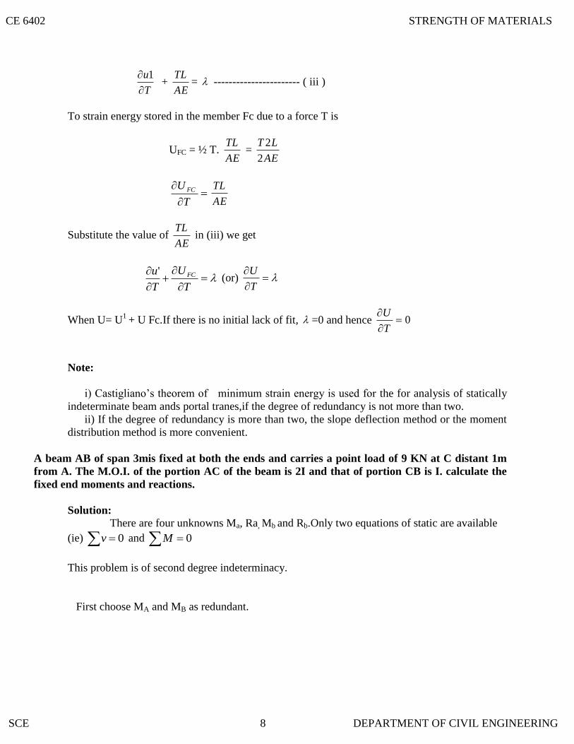
T
u
1 +
AE
TL= ----------------------- ( iii )
To strain energy stored in the member Fc due to a force T is
UFC = ½ T. AE
TL =
AE
LT
2
2
T
U FC
AE
TL
Substitute the value of AE
TL in (iii) we get
T
U
T
u FC' (or)
T
U
When U= U1
+ U Fc.If there is no initial lack of fit, =0 and hence 0
T
U
Note:
i) Castigliano‟s theorem of minimum strain energy is used for the for analysis of statically
indeterminate beam ands portal tranes,if the degree of redundancy is not more than two.
ii) If the degree of redundancy is more than two, the slope deflection method or the moment
distribution method is more convenient.
A beam AB of span 3mis fixed at both the ends and carries a point load of 9 KN at C distant 1m
from A. The M.O.I. of the portion AC of the beam is 2I and that of portion CB is I. calculate the
fixed end moments and reactions.
Solution:
There are four unknowns Ma, Ra, Mb and Rb.Only two equations of static are available
(ie) 0v and 0M
This problem is of second degree indeterminacy.
First choose MA and MB as redundant.
CE 6402 STRENGTH OF MATERIALS
SCE 8 DEPARTMENT OF CIVIL ENGINEERING

δA=
dxR
M
EI
Mx
R
UA
x
A
AB 0 -----------(1)
θA= dxM
M
EI
M
M
U
A
xx
B
AA
AB
0 -------------(2)
1) For portion AC:
Taking A as the origin
Mx = -MA + RA x
1;
A
x
A
x
M
Mx
R
M
IIOM 2.. Limits of x: 0 to 1m
Hence
dxEI
dxR
M
EI
M
A
x
C
A
x
1
0
AA
2
x xR M-
232
1
3
1
2
1
2
132
AA
AA
MR
EI
RM
EI
And
dx
EIdx
R
M
EI
M
A
x
C
A
x
1
0
AA
2
1 xR M-
22
1
2
11
2
12
AA
AA
RM
EI
RM
EI
For portion CB, Taking A as the origin we have
xM = )1(9 XXRM AA
1;
A
x
A
x
M
Mx
R
M
M.O.I = I Limits of x : 1 to 3 m
CE 6402 STRENGTH OF MATERIALS
SCE 9 DEPARTMENT OF CIVIL ENGINEERING

Hence
dxEI
dxR
M
EI
M
A
x
B
C
x
3
1
AA x1)-9(x- xR M-
=
42
3
264
1AA RM
EI
And
dx
EIdx
M
M
EI
M
A
x
B
C
x
3
1
AA 1-1)-9(x- xR M-
= 18421
AA RMEI
Subs these values in (1) & (2) we get
0
A
AB
R
U
042
3
264
1
23
1
AA
AA RMEI
MR
EI
2.08 – MA = 9.88 __________ (3)
0
A
AB
M
U
01842
1
212
1
AA
AA RMEI
RM
EI
MA – 1.7RA = -7.2 -------------- (4)
Solving (3) & (4)
MA = 4.8 KN – M (assumed direction is correct)
RA = 7.05 KN
CE 6402 STRENGTH OF MATERIALS
SCE 10 DEPARTMENT OF CIVIL ENGINEERING

To find MB, take moments at B, and apply the condition 0M there. Taking clockwise
moment as positive and anticlockwise moment as negative. Taking MB clockwise, we have
MB – MA =RA (3) – 9x2 = 0
MB – 4.8 + (7.05x 3) -18 = 0
MB = 1.65 KN – m (assumed direction is correct)
To find RB Apply 0V for the whole frame.
RB = 9 – RA = 9-7.05 = 1.95 KN
Using Castigliano’s First Theorem, determine the deflection and rotation of the
overhanging end A of the beam loaded.
Sol:
Rotation of A:
RB x L = -M
RB = -M/L
RB = M/L ( )
& RC = M/L ( )
B
C
x
x
x
x
B
A
A dxM
MM
EIdx
M
MM
EIM
U..
1.
1 ____________ (1)
For any point distant x from A, between A and B (i.e.) x = 0 to x = L/3
Mx = M ; and 1
M
M x ________ (2)
For any point distant x from C, between C and B (i.e.) x = 0 to x = L
Mx = (M/L) x ; and L
x
M
M x
________ (3)
Subs (2) & (3) in (1)
CE 6402 STRENGTH OF MATERIALS
SCE 11 DEPARTMENT OF CIVIL ENGINEERING

LL
A dxL
xx
L
M
EIdxM
EIM
U
0
3/
0
1).1(
1
EI
ML
EI
ML
33
)(
3
2clockwise
EI
ML
b) Deflection of A:
To find the deflection at A, apply a fictitious load W at A, in upward direction as
shown in fig.
)
3
4( WLMxLRB
L
WLMRB
1)
3
4(
L
WLMRB
1)
3
4(
L
WLMRC
1)
3
1(
dxW
MM
EIW
MM
EIW
U x
x
B
C
x
B
A
xA .11
For the portion AB, x = 0 at A and x = L/3 at B
Mx = M + Wx
xW
M x
For the portion CB, x = 0 at C and x = L at B
xL
WLMM x .1
8
1
3
x
W
M x
dxx
L
xWLM
EIxWxM
EI
LL
A
0
3/
03
.3
111
CE 6402 STRENGTH OF MATERIALS
SCE 12 DEPARTMENT OF CIVIL ENGINEERING

1.10 STATE THE DEFLECTION OF THE JOINT DUE TO LINEAR DEFORMATION
1.9 STATE THE VARIOUS METHODS FOR COMPUT
1.8 STRAIN ENERGY STORED IN A ROD OF LENGTH L AND AXIAL RIGIDITY AE TO
1.7 PRINCIPLE OF VIRTUAL WORK
Putting W = 0
dxL
Mx
EIdxMx
EI
LL
A
0
23/
03
11
LL
A
x
EI
Mx
EI
M0
33/
0
2
)3
(3
)2
(
EI
ML
EI
MLA
918
22
EI
MLA
6
2
It states that the workdone on a structure by external loads is equal to the internal energy
stored in a structure (Ue = Ui)
Work of external loads = work of internal loads
AN AXIAL FORCE P
Strain energy stored
P2 L
U= --------
2AE
ING THE JOINT DEFLECTION OF
A PERFECT FRAME
1. The Unit Load method
2. Deflection by Castigliano‟s First Theorem
3. Graphical method : Willot – Mohr Diagram
n
δv = Σ U x ∆
1
n
δH = Σ U‟ x ∆
1
CE 6402 STRENGTH OF MATERIALS
SCE 13 DEPARTMENT OF CIVIL ENGINEERING

1.12 STATE THE DEFLECTION OF A JOINT DUE TO LACK OF FIT
1.11 THE DEFLECTIO
PL
∆ = ---------
Ae
U= vertical deflection
U‟= horizontal deflection
N OF JOINT DUE TO TEMPERATURE VARIATION
n
δ = Σ U X A
1
= U1∆1 + U2 ∆2 + …………+ Un ∆n
If the change in length (∆) of certain member is zero, the product U.∆ for those members
will be substituted as zero in the above equation.
n
δ = Σ U ∆
1
= U1∆1 + U2 ∆2 + …………+ Un ∆n
If there is only one member having lack of fit ∆1, the deflection of a particular joint will be
equal to U1∆1.
Determine the vertical and horizontal displacements of the point C of the pin-jointed frame
shown in fig. The cross sectional area of AB is 100 sqmm and of AC and BC 150 mm2 each.
E= 2 x 10 5 N/mm
2. (By unit load method)
Sol:
The vertical and horizontal deflections of the joint C are given by
AE
LPu
AE
PuL
H
V
'
A) Stresses due to External Loading:
AC = m543 22
Reaction:
RA = -3/4
RB = 3/4
Sin θ = 3/5 = 0.6; Cos θ = 4/5 = 0.8
Resolving vertically at the joint C, we get
6 = PAC cos θ + PBC sin θ
Resolving horizontally at the joint C, we get
PAC cos θ = PBC sin θ; PAC = PBC
CE 6402 STRENGTH OF MATERIALS
SCE 14 DEPARTMENT OF CIVIL ENGINEERING
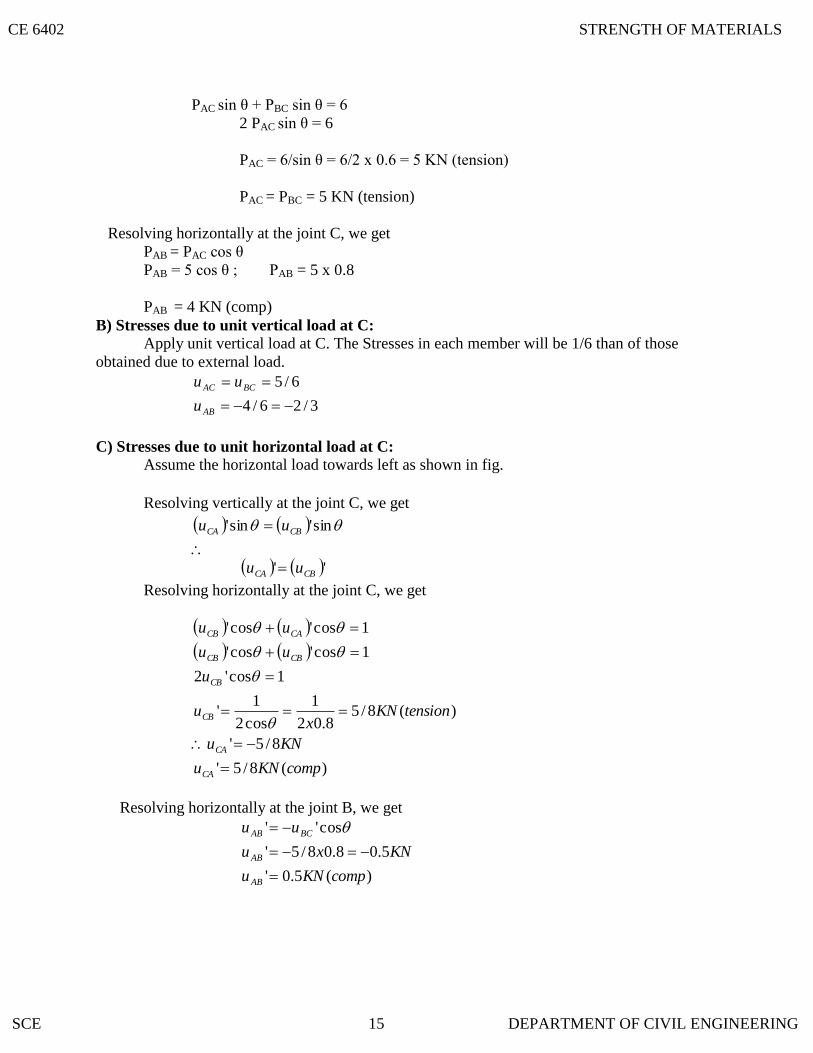
PAC sin θ + PBC sin θ = 6
2 PAC sin θ = 6
PAC = 6/sin θ = 6/2 x 0.6 = 5 KN (tension)
PAC = PBC = 5 KN (tension)
Resolving horizontally at the joint C, we get
PAB = PAC cos θ
PAB = 5 cos θ ; PAB = 5 x 0.8
PAB = 4 KN (comp)
B) Stresses due to unit vertical load at C:
Apply unit vertical load at C. The Stresses in each member will be 1/6 than of those
obtained due to external load.
3/26/4
6/5
AB
BCAC
u
uu
C) Stresses due to unit horizontal load at C:
Assume the horizontal load towards left as shown in fig.
Resolving vertically at the joint C, we get
sin'sin' CBCA uu
'' CBCA uu
Resolving horizontally at the joint C, we get
)(8/5'
8/5'
)(8/58.02
1
cos2
1'
1cos'2
1cos'cos'
1cos'cos'
compKNu
KNu
tensionKNx
u
u
uu
uu
CA
CA
CB
CB
CBCB
CACB
Resolving horizontally at the joint B, we get
)(5.0'
5.08.08/5'
cos''
compKNu
KNxu
uu
AB
AB
BCAB
CE 6402 STRENGTH OF MATERIALS
SCE 15 DEPARTMENT OF CIVIL ENGINEERING
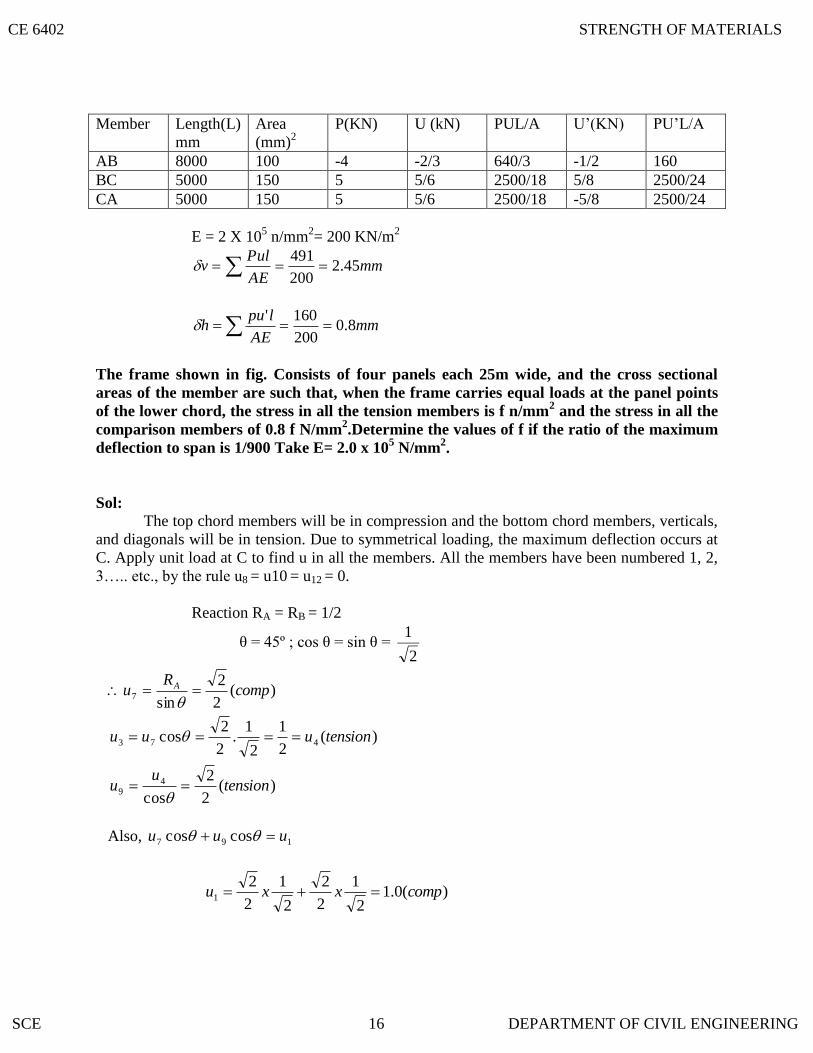
Member Length(L)
mm
Area
(mm)2
P(KN) U (kN) PUL/A U‟(KN) PU‟L/A
AB 8000 100 -4 -2/3 640/3 -1/2 160
BC 5000 150 5 5/6 2500/18 5/8 2500/24
CA 5000 150 5 5/6 2500/18 -5/8 2500/24
E = 2 X 10⁵ n/mm
2= 200 KN/m
2
v mm
AE
Pul45.2
200
491
mmAE
lpuh 8.0
200
160'
The frame shown in fig. Consists of four panels each 25m wide, and the cross sectional
areas of the member are such that, when the frame carries equal loads at the panel points
of the lower chord, the stress in all the tension members is f n/mm2 and the stress in all the
comparison members of 0.8 f N/mm2.Determine the values of f if the ratio of the maximum
deflection to span is 1/900 Take E= 2.0 x 10⁵ N/mm
2.
Sol:
The top chord members will be in compression and the bottom chord members, verticals,
and diagonals will be in tension. Due to symmetrical loading, the maximum deflection occurs at
C. Apply unit load at C to find u in all the members. All the members have been numbered 1, 2,
3….. etc., by the rule u8 = u10 = u12 = 0.
Reaction RA = RB = 1/2
θ = 45º ; cos θ = sin θ = 2
1
)(2
2
cos
)(2
1
2
1.
2
2cos
)(2
2
sin
49
473
7
tensionu
u
tensionuuu
compR
u A
Also, 197 coscos uuu
)(0.1
2
1
2
2
2
1
2
21 compxxu
CE 6402 STRENGTH OF MATERIALS
SCE 16 DEPARTMENT OF CIVIL ENGINEERING
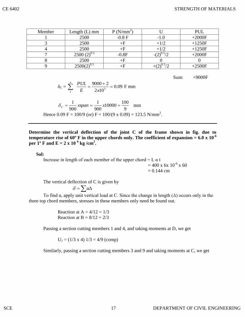
Member Length (L) mm P (N/mm2) U PUL
1 2500 -0.8 F -1.0 +2000F
3 2500 +F +1/2 +1250F
4 2500 +F +1/2 +1250F
7 2500 (2)0.5
-0.8F -(2)0.5
/2 +2000F
8 2500 +F 0 0
9 2500(2)0.5
+F +(2)0.5
/2 +2500F
Sum: +9000F
δC = 09.0102
290005
1
xE
PULn
F mm
9
10010000
900
1
900
1 xxspanC mm
Hence 0.09 F = 100/9 (or) F = 100/(9 x 0.09) = 123.5 N/mm2.
Determine the vertical deflection of the joint C of the frame shown in fig. due to
temperature rise of 60º F in the upper chords only. The coefficient of expansion = 6.0 x 10⁻⁶
per 1º F and E = 2 x 10 6 kg /cm
2.
Sol: Increase in length of each member of the upper chord = L α t
= 400 x 6x 10-6
x 60
= 0.144 cm
The vertical deflection of C is given by
u
To find u, apply unit vertical load at C. Since the change in length (∆) occurs only in the
three top chord members, stresses in these members only need be found out.
Reaction at A = 4/12 = 1/3
Reaction at B = 8/12 = 2/3
Passing a section cutting members 1 and 4, and taking moments at D, we get
U1 = (1/3 x 4) 1/3 = 4/9 (comp)
Similarly, passing a section cutting members 3 and 9 and taking moments at C, we get
CE 6402 STRENGTH OF MATERIALS
SCE 17 DEPARTMENT OF CIVIL ENGINEERING

Also
332211
12
3
)(9
4
)(9
8
3
14
3
2
uuu
compuu
compxu
C
cm
x
C
C
256.0
)144.0(9
8
9
4
9
4
Using the principle of least work, analyze the portal frame shown in Fig. Also plot the
B.M.D.
Sol:
The support is hinged. Since there are two equations at each supports. They are HA, VA, HD,
and VD. The available equilibrium equation is three. (i.e.) 0,0,0 VHM .
The structure is statically indeterminate to first degree. Let us treat the horizontal H ( ) at A
as redundant. The horizontal reaction at D will evidently be = (3-H) ( ). By taking moments at
D, we get
(VA x 3) + H (3-2) + (3 x 1) (2 – 1.5) – (6 x 2) = 0
VA = 3.5 – H/3
VD = 6 – VA = 2.5 + H/3
By the theorem of minimum strain energy,
0
0
H
U
H
U
H
U
H
U
H
U
DCCEBEAB
(1)For member AB: Taking A as the origin.
CE 6402 STRENGTH OF MATERIALS
SCE 18 DEPARTMENT OF CIVIL ENGINEERING

dxH
MM
EIH
U
xH
M
xHx
M
AB
3
0
2
1
.2
.1
12.1091
83
1
2
1
3
0
43
23
0
HEI
xHx
EI
dxxHxx
EI
(2) For the member BE:
Taking B as the origin.
dxH
MM
EIH
U
x
H
M
HxxHM
xH
xxHM
BE
1
0
1
33
35.35.43
35.35.1133
dxxHx
xHEI
3
33
5.35.431
1
0
dxHx
xxHxHxxHEI
9
67.15.15.105.1391 2
2
1
0
dxHx
xHxxHEI
9
67.12125.1391 2
2
1
0
CE 6402 STRENGTH OF MATERIALS
SCE 19 DEPARTMENT OF CIVIL ENGINEERING

1
0
3322
27389.065.139
1
HxxHxxxHx
EI
27389.065.139
1 2 HHH
EI
9.791
HEI
(3) For the member CE:
Taking C as the origin
2
0
3
1
35.226
)3
5.2(2)3(
H
MM
EIH
U
HxxHM
xH
xHM
CE
=
2
03
23
5.2261 xHx
xHEI
dxHx
xHxxHxxHEI
9
833.067.6267.654121 2
2
2
0
dxHx
xxHxxHEI
9
833.0234.1334121 2
2
2
0
= EI
1(10.96H - 15.78)
(4) For the member DC:
Taking D as the origin
xx
M
HxxxHM
33
dxH
MM
EIH
U DC
2
0
1
dxxHxxEI
31
2
0
dxHxxEI
22
2
0
31
CE 6402 STRENGTH OF MATERIALS
SCE 20 DEPARTMENT OF CIVIL ENGINEERING

dxHxx
EI
2
0
33
33
31
dx
Hxx
EI
2
0
33
3
1
= EI
1(2.67H -8)
Subs the values
0
H
U
1/EI (9-10.2) + (8.04H-7.9) + (10.96H-15.78) + (-8+2.67H) = 0
30.67H = 41.80
H = 1.36 KN
Hence
VA = 3.5 - H/3 = 3.5 - 1.36/3 = 3.05 KN
VD = 2.5 + H/3 = 2.5 + 1.36/3 = 2.95 KN
MA= MD =0
MB = (-1 x 32)/2 + (1.36 x 3) = -0.42 KN –m
MC = - (3-H) 2 = - (3-1.36)2 =-3.28KNm
Bending moment Diagram:
A simply supported beam of span 6m is subjected to a concentrated load of 45 KN at 2m
from the left support. Calculate the deflection under the load point. Take E = 200 x 106
KN/m2 and I = 14 x 10
-6 m
4.
Solution:
Taking moments about B.
VA x 6 – 45 x 4=0
VA x 6 -180 = 0
VA = 30 KN
VB = Total Load – VA = 15 KN
Virtual work equation:
EI
mMdxL
c 0
V
Apply unit vertical load at c instead of 45 KN
RA x 6-1 x 4 =0
RA = 2/3 KN
CE 6402 STRENGTH OF MATERIALS
SCE 21 DEPARTMENT OF CIVIL ENGINEERING

RB = Total load –RA = 1/3 KN
Virtual Moment:
Consider section between AC
M1 = 2/3 X1 [limit 0 to 2]
Section between CB
M2 = 2/3 X2-1 (X2-2 ) [limit 2 to 6 ]
Real Moment:
The internal moment due to given loading
M1= 30 x X1
M2 = 30 x X2 -45 (X2 -2)
6
2
222111
2
0
VEI
dxMm
EI
dxMmc
2
0
6
2
22222
2
1
2
0
6
2
2
222
1
11
90453023
220
1
2453023
230
3
2
dxxxxxxEI
dxEI
xxxx
dxEI
xx
2
0
222
6
2
2
1 901523
201
dxxx
xEI
2
0
222
2
2
6
2
2
1 18030305201
dxxxxxEI
6
2
2
3
2
3
2
3
0
1 1802
60
3
5
3
201
x
xxx
EI
=
216180263026
3
51
3
820 2233
EIEI
CE 6402 STRENGTH OF MATERIALS
SCE 22 DEPARTMENT OF CIVIL ENGINEERING

Define and prove the Maxwell’s reciprocal theorem.
mmormxxxEI
EI
1.57)(0571.0101410200
160160
72096067.34633.531
66
The deflection under the load = 57.1 mm
The Maxwell‟s reciprocal theorem stated as “ The work done by the first system loads
due to displacements caused by a second system of loads equals the work done by the second
system of loads due to displacements caused by the first system of loads”.
Maxwell‟s theorem of reciprocal deflections has the following three versions:
1. The deflection at A due to unit force at B is equal to deflection at B due to unit force
at A.
δAB = δBA
2. The slope at A due to unit couple at B is equal to the slope at B due to unit couple A
ΦAB = ΦBA
3. The slope at A due to unit load at B is equal to deflection at B due to unit couple.
'
' ABAB
Proof:
By unit load method,
EI
Mmdx
Where,
M= bending moment at any point x due to external load.
m= bending moment at any point x due to unit load applied at the point where
deflection is required.
Let mXA=bending moment at any point x due to unit load at A
Let mXB = bending moment at any point x due to unit load at B.
When unit load (external load) is applied at A,
CE 6402 STRENGTH OF MATERIALS
SCE 23 DEPARTMENT OF CIVIL ENGINEERING

M=mXA
To find deflection at B due to unit load at A, apply unit load at B.Then m= mXB
Hence,
dxEI
mm
EI
Mmdx XBXABA
. ____________ (i)
Similarly,
When unit load (external load) is applied at B, M=mXB
To find the deflection at A due to unit load at B, apply unit load at A.then m= mXA
dxEI
mmB
EI
Mmdx XAAB
. ____________ (ii)
Comparing (i) & (ii) we get
δAB = δBA
Using Castigliano’s theorem, determine the deflection of the free end of the cantilever beam
shown in the fig. Take EI = 4.9 MN/m2.
Solution:
Apply dummy load W at B. Since we have to determine the deflection of the free end.
Consider a section xx at a distance x from B. Then
2165.1*1*20130 xxxWxM x
dx
W
M
EI
M
dxxxxxxxWxdxxx
xxxxWxxdxWxEI
2
1
3
2
1
0
)2(16*)5.1(1*20)1(30*)2
1)(1(20)1(30**
1
CE 6402 STRENGTH OF MATERIALS
SCE 24 DEPARTMENT OF CIVIL ENGINEERING

3
2
23
23233
2
1
2342331
0
3
31675.0
320
2230
3
23
2
410
2330
3
3
3
1
xx
xxxxWx
xxxxxWxxW
EI
Putting W =0
5
3
191675.3
3
1920
2
5
3
1930
2
3
3
14
4
1510
2
3
3
730
1
EI
3
41658.2*20
6
2330
2
710
6
530
1
EI
mmorm
x
x
64.44)(446.0
33.216.5111583.525109.4
1016
3
A cantilever, 8m long, carrying a point loads 5 KN at the center and an udl of 2 KN/m for a
length 4m from the end B. If EI is the flexural rigidity of the cantilever find the reaction at
the prop. (NOV/DEC – 2004)
Solution:
To find Reaction at the prop, R (in KN)
Portion AC: ( origin at A )
EI
R
EI
R
EI
xR
EI
dxRxU
3
32
6
64
62
224
0
3224
0
1
Portion CB: ( origin at C )
Bending moment Mx = R (x+4) – 5x – 2x2/2
= R (x+4) – 5x –x2
EI
dxMU x
2
24
0
2
CE 6402 STRENGTH OF MATERIALS
SCE 25 DEPARTMENT OF CIVIL ENGINEERING

Total strain energy = U1 +U2
At the propped end 0
R
U
dxdR
dMx
EI
M
EI
R
R
U xx
4
03
64
= dxxxxxREIEI
R)4(54
1
3
64 22
4
0
dxxxxxxREIEI
R)4(454
1
3
64 224
0
dxxxxxxxREIEI
R)4()4(5168
1
3
64 2322
4
0
0
4
0
342
32
3
)3
4
4()2
3(5164
3
1
3
64
xxx
xxx
xR
EIEI
R
)
3
256
4
256()32
3
64(56464
3
64
3
64R
R
= 21.33 R + (149.33R – 266.67 – 149.33)
= 21.33 R + (149.33 R – 416)
21.33 R +149.33 R – 416 =0
R = 2.347 KN
A simply supported beam of span L is carrying a concentrated load W at the centre and a uniformly
distributed load of intensity of w per unit length. Show that Maxwell‟s reciprocal theorem holds good at
the centre of the beam.
Solution:
Let the load W is applied first and then the uniformly distributed load w.
Deflection due to load W at the centre of the beam is given by
EI
WlW
384
5 4
Hence work done by W due to w is given by:
CE 6402 STRENGTH OF MATERIALS
SCE 26 DEPARTMENT OF CIVIL ENGINEERING

STATE THE COMPARISON OF CASTIGLIANO’S FIRST THEOREM AND UNIT
1.14 STATE THE ASSUMPTIONS MADE IN THE UNIT LOAD METHO
1.13 STATE THE DIFFERENCE BETWEEN UNIT LOAD AND STRAIN ENERGY
EI
wlWxU BA
384
5 4
,
Deflection at a distance x from the left end due to W is given by
22 4348
xxlEI
WxW
Work done by w per unit length due to W,
dxxxlEI
WwxU
l
AB )43(48
2 22
2/
0
,
422
,222
3
24
lll
EI
WwU AB
168
3
24
44
,
ll
EI
WwU AB
EI
WwlU BA
4
,384
5
Hence proved.
METHOD IN THE DETERMINATION OF STRUCTURES.
In strain energy method, an imaginary load P is applied at the point where the deflection is
desired to be determined. P is equated to zero in the final step and the deflection is obtained.
In the Unit Load method, a unit load (instead of P) is applied at the point where the deflection
is desired.
D
2. The external and internal forces are in equilibrium
3. Supports are rigid and no movement is possible
4. The material is strained well within the elastic limit.
LOAD METHOD The deflection by the unit load method is given by
n PUL
CE 6402 STRENGTH OF MATERIALS
SCE 27 DEPARTMENT OF CIVIL ENGINEERING
STATE IN WHICH CASES, CASTIGLIANO’S THEOREM CAN BE USED
1.17 STATE THE TWO TYPES OF STRAIN ENERGIES
1.16 PERFECT FRAME
1.15 DEGREE OF REDUNDANCY
STATE MAXWELL’S RE
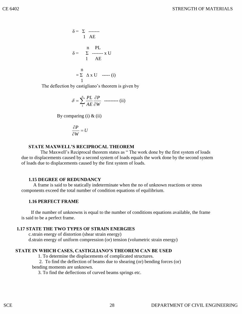
δ = Σ -------
1 AE
n PL
δ = Σ ------- x U
1 AE
n
= Σ ∆ x U ----- (i)
1
The deflection by castigliano‟s theorem is given by
n
W
P
AE
PL
1
--------- (ii)
By comparing (i) & (ii)
UW
P
CIPROCAL THEOREM
The Maxwell‟s Reciprocal theorem states as “ The work done by the first system of loads
due to displacements caused by a second system of loads equals the work done by the second system
of loads due to displacements caused by the first system of loads.
A frame is said to be statically indeterminate when the no of unknown reactions or stress
components exceed the total number of condition equations of equilibrium.
If the number of unknowns is equal to the number of conditions equations available, the frame
is said to be a perfect frame.
c. strain energy of distortion (shear strain energy)
d.strain energy of uniform compression (or) tension (volumetric strain energy)
1. To determine the displacements of complicated structures.
2. To find the deflection of beams due to shearing (or) bending forces (or)
bending moments are unknown.
3. To find the deflections of curved beams springs etc.
CE 6402 STRENGTH OF MATERIALS
SCE 28 DEPARTMENT OF CIVIL ENGINEERING

2.4 STATE THE DEGREE OF INDETERMINACY IN THE GIVEN BEAM
2.3 STATE THE
2.2 STATE THE DEGREE OF INDETERMINACY IN PROPPED CANTILEVER
CHAPTER- II
2.1 STATICALLY INDETERMINATE BEA
INDETERMINATE BEAMS
Propped Cantilever and fixed end moments and reactions for concentrated load (central, non
central), uniformly distributed load, triangular load (maximum at centre and maximum at end) –
Theorem of three moments – analysis of continuous beams – shear force and bending moment
diagrams for continuous beams (qualitative study only)
MS
If the numbers of reaction components are more than the conditions equations, the structure is
defined as statically indeterminate beams.
E = R – r
E = Degree of external redundancy
R = Total number of reaction components
r = Total number of condition equations available.
A continuous beam is a typical example of externally indeterminate structure.
For a general loading, the total reaction components (R) are equal to (3+2) =5,
While the total number of condition equations (r) are equal to 3. The beam is statically
indeterminate, externally to second degree. For vertical loading, the beam is statically
determinate to single degree.
E = R – r
= 5 – 3 = 2
DEGREE OF INDETERMINACY IN A FIXED BEAM
For a general system of loading, a fixed beam is statically indeterminate to third degree. For vertical
loading, a fixed beam is statically indeterminate to second degree.
E = R – r
For general system of loading:
R = 3 + 3 and r = 3
E = 6-3 = 3
For vertical loading:
R = 2+2 and r = 2
E = 4 – 2 = 2
The beam is statically indeterminate to third degree of general system of loading.
R = 3+1+1+1 = 6
E = R-r
= 6-3 = 3
CE 6402 STRENGTH OF MATERIALS
SCE 29 DEPARTMENT OF CIVIL ENGINEERING

2.9 WRITE THE EXPRESSION FIXED END MOMENTS FOR A FIXED DUE TO
2.8 WRITE THE EXPRESSION FIXED END MOMENTS AND DEFLECTION FOR A
2.7 WRITE THE EXPRESSION FIXED END MOMENTS AND DEFLECTION FOR A
2.6 STATE
2.5 STATE THE DEGREE OF INDETERMINACY IN THE GIVEN BEAM
The beam is statically determinate. The total numbers of condition equations are equal to 3+2 =
5. Since, there is a link at B. The two additional condition equations are at link.
E = R-r
= 2+1+2-5
= 5-5
E = 0
THE METHODS AVAILABLE FOR ANALYZING STATICALLY
INDETERMINATE STRUCTURES i. Compatibility method
ii. Equilibrium method
FIXED BEAM CARRYING POINT LOAD AT CENTRE
EI
WLy
WLMM BA
192
83
max
FIXED BEAM CARRYING ECCENTRIC POINT LOAD
)(3 3
33
max
2
2
2
2
loadtheunderEIL
bWay
L
bWaM
L
WabM
B
A
SINKING OF SUPPORT
2
6
L
EIMM BA
CE 6402 STRENGTH OF MATERIALS
SCE 30 DEPARTMENT OF CIVIL ENGINEERING

A fixed beam AB of length 6m carries point load of 160 kN and 120 kN at a distance of 2m and 4m
from the left end A. Find the fixed end moments and the reactions at the supports. Draw B.M and
S.F diagrams.
Solution:
Given: L = 6m
Load at C, WC = 160 kN
Load at D, WC = 120 kN
Distance AC = 2m
Distance AD =4m
First calculate the fixed end moments due to loads at C and D separately and then
add up the moments.
Fixed End Moments:
For the load at C, a=2m and b=4m
kNmxx
M
L
abWM
A
C
A
22.142)6(
)4(21602
2
1
2
2
1
kNmxx
M
L
baWM
B
C
B
11.71)6(
)4(21602
2
1
2
2
1
For the load at D, a = 4m and b = 2m
kNmxx
M
L
baWM
A
DA
33.53)6(
)4(21202
2
2
2
2
2
kNmxx
M
L
baWM
B
DB
66.106)6(
)4(21602
2
2
2
2
2
Total fixing moment at A,
MA = MA1 + MA2
= 142.22 + 53.33
MA = 195.55 kNm
Total fixing moment at B,
MB =MB1 + MB2
= 71.11 + 106.66
CE 6402 STRENGTH OF MATERIALS
SCE 31 DEPARTMENT OF CIVIL ENGINEERING

= 177.77 kN m
B.M diagram due to vertical loads:
Consider the beam AB as simply supported. Let RA* and RB
* are the reactions at
A and B due to simply supported beam. Taking moments about A, we get
kNR
xxxR
B
B
33.1336
800
412021606
*
*
RA*
= Total load - RB*=(160 +120) – 133.33 = 146.67 kN
B.M at A = 0
B.M at C = RA* x 2 = 146.67 x 2 = 293.34 kN m
B.M at D = 133.33 x 2 = 266.66 kN m
B.M at B= 0
S.F Diagram:
Let RA = Resultant reaction at A due to fixed end moments and vertical loads
RB = Resultant reaction at B
Equating the clockwise moments and anti-clockwise moments about A,
RB x 6 + MA = 160 x 2 + 120 x 4 + MB
RB= 130.37 kN
RA = total load – RB = 149.63 kN
S.F at A = RA = 149.63 kN
S.F at C = 149.63- 160 = -10.37 kN
S.F at D = -10.37 – 120 = -130.37 kN
S.F at B= 130.37 KN
A fixed beam AB of length 6m carries two point loads of 30 kN each at a distance of 2m
from the both ends. Determine the fixed end moments and draw the B.M diagram.
Sloution:
Given:
Length L = 6m
Point load at C = W1 = 30 kN
Point load at D = W2= 30 kN
Fixed end moments: MA = Fixing moment due to load at C + Fixing moment due to load at D
mkNxxxx
L
baW
L
baW
406
2430
6
42302
2
2
2
2
2
222
2
2
111
Since the beam is symmetrical, MA = MB = 40 kNm
CE 6402 STRENGTH OF MATERIALS
SCE 32 DEPARTMENT OF CIVIL ENGINEERING

B.M Diagram:
To draw the B.M diagram due to vertical loads, consider the beam AB as simply supported.
The reactions at A and B is equal to 30kN.
B.M at A and B = 0
B.M at C =30 x 2 = 60 kNm
B.M at D = 30 x 2 = 60 kNm
Find the fixing moments and support reactions of a fixed beam AB of length 6m, carrying a uniformly
distributed load of 4kN/m over the left half of the span.
Solution:
Macaulay‟s method can be used and directly the fixing moments and end reactions can be
calculated. This method is used where the areas of B.M diagrams cannot be determined conveniently.
For this method it is necessary that UDL should be extended up to B and then compensated for upward
UDL for length BC
The bending at any section at a distance x from A is given by,
EI22
2 xwxMxR
dx
ydAA +w*(x-3)
2
)3( x
=RAx – MA- (2
24x) +4(
2
)3 2x)
= RAx – MA- 2x2 +2(x-3)
2
Integrating, we get
EIdx
dy=RA
2
2x-MAx - 2
3
3x+C1 +
3
)3(2 3x -------(1)
When x=0, dx
dy=0.
Substituting this value in the above equation up to dotted line,
C1 = 0
Therefore equation (1) becomes
EIdx
dy=RA
2
2x-MAx - 2
3
3x +
3
)3(2 3x
Integrating we get
12
)3(2
12
2
26
4
2
423
xC
xxMxRyEI A
A
When x = 0 , y = 0
By substituting these boundary conditions upto the dotted line,
C2 = 0
6
)3(1
626
4423
xxxMxR
yEI AA ________(ii)
CE 6402 STRENGTH OF MATERIALS
SCE 33 DEPARTMENT OF CIVIL ENGINEERING
2.9 STATE THE
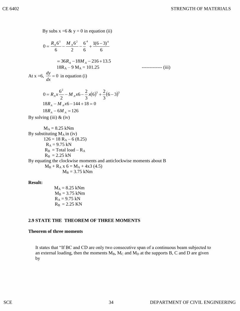
By subs x =6 & y = 0 in equation (ii)
6
)36(1
6
6
2
6
6
60
4423
AA MR
5.132161836 AA MR
18RA – 9 MA = 101.25 ------------- (iii)
At x =6, 0dx
dy in equation (i)
332
363
26
3
26
2
60 xxMxR AA
126618
018144618
AA
AA
MR
xMR
By solving (iii) & (iv)
MA = 8.25 kNm
By substituting MA in (iv)
126 = 18 RA – 6 (8.25)
RA = 9.75 kN
RB = Total load – RA
RB = 2.25 kN
By equating the clockwise moments and anticlockwise moments about B
MB + RA x 6 = MA + 4x3 (4.5)
MB = 3.75 kNm
Result:
MA = 8.25 kNm
MB = 3.75 kNm
RA = 9.75 kN
RB = 2.25 KN
THEOREM OF THREE MOMENTS
Theorem of three moments
It states that “If BC and CD are only two consecutive span of a continuous beam subjected to
an external loading, then the moments MB, MC and MD at the supports B, C and D are given
by
CE 6402 STRENGTH OF MATERIALS
SCE 34 DEPARTMENT OF CIVIL ENGINEERING

2.10 EXPLAIN THE EFFECT OF SETTLEMENT OF SUPPORTS IN A CONTINUOUS
2
_
22
1
1
_
12211
66.)(2
L
xa
L
xaLMLLMLM DCB
Where
MB = Bending Moment at B due to external loading
MC = Bending Moment at C due to external loading
MD = Bending Moment at D due to external loading
L1 = length of span AB
L2 = length of span BC
a1 = area of B.M.D due to vertical loads on span BC
a2 = area of B.M.D due to vertical loads on span CD
1
_
x = Distance of C.G of the B.M.D due to vertical loads on BC from B
2
_
x = Distance of C.G of the B.M.D due to vertical loads on CD from D.
What are the fixed end moments for a fixed beam of length ‘L’ subjected to a concentrated
load ‘w’ at a distance ‘a’ from left end?
Fixed End Moment:
2
2
2
2
L
WabM
L
WabM
B
A
BEAM
Due to the settlement of supports in a continuous beam, the bending stresses will alters
appreciably. The maximum bending moment in case of continuous beam is less when compare to the
simply supported beam.
ADVANTAGES OF CONTINUOUS BEAMS OVER SIMPLY SUPPORTED BEAMS (i)The maximum bending moment in case of a continuous beam is much less than in case of a
simply supported beam of same span carrying same loads.
(ii) In case of a continuous beam, the average B.M is lesser and hence lighter materials of
construction can be used it resist the bending moment.
A fixed beam of length 5m carries a uniformly distributed load of 9 kN/m run over the
entire span. If I = 4.5x10⁻⁴
m4 and E = 1x10
7 kN/m
2, find the fixing moments at the ends and
deflection at the centre.
CE 6402 STRENGTH OF MATERIALS
SCE 35 DEPARTMENT OF CIVIL ENGINEERING

Solution:
Given:
L = 5m
W = 9 kN/m2 , I = 4.5x10
-4 m
4 and E = 1x10
7 kN/m
2
(i) The fixed end moment for the beam carrying udl:
MA = MB = 12
2WL
= KNmx
75.1812
)5(9 2
(ii) The deflection at the centre due to udl:
mmxxxx
xy
EI
WLy
c
c
254.3105.4101384
)5(9
384
47
4
4
Deflection is in downward direction.
A fixed beam AB, 6m long is carrying a point load of 40 kN at its center. The M.O.I of the
beam is 78 x 106 mm
4 and value of E for beam material is 2.1x10
5 N/mm
2. Determine (i)
Fixed end moments at A and B.
Solution:
Fixed end moments:
8
WLMM BA
kNmx
MM BA 5.378
650
A fixed beam AB of length 3m is having M.O.I I = 3 x 106 mm
4 and value of E for beam
material is 2x10⁵ N/mm
2. The support B sinks down by 3mm. Determine (i) fixed end
moments at A and B.
Solution:
Given:
L = 3m = 3000mm
I = 3 x 106 mm
4
E = 2x10⁵ N/mm
2
= 3mm
CE 6402 STRENGTH OF MATERIALS
SCE 36 DEPARTMENT OF CIVIL ENGINEERING
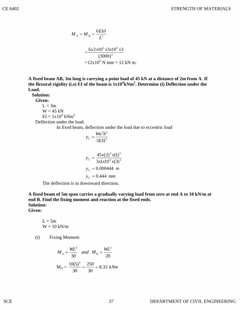
2
6
L
EIMM BA
=2
65
)3000(
31031026 xxxxx
=12x105 N mm = 12 kN m.
A fixed beam AB, 3m long is carrying a point load of 45 kN at a distance of 2m from A. If
the flexural rigidity (i.e) EI of the beam is 1x10⁴kNm
2. Determine (i) Deflection under the
Load.
Solution:
Given:
L = 3m
W = 45 kN
EI = 1x10⁴ kNm
2
Deflection under the load:
In fixed beam, deflection under the load due to eccentric load
3
33
3EIL
bWayC
mmy
my
xxx
xxy
C
C
C
444.0
000444.0
)3(1013
)1()2(4524
33
The deflection is in downward direction.
A fixed beam of 5m span carries a gradually varying load from zero at end A to 10 kN/m at
end B. Find the fixing moment and reaction at the fixed ends.
Solution:
Given:
L = 5m
W = 10 kN/m
(i) Fixing Moment:
2030
22 WLMand
WLM BA
MA = kNm33.830
250
30
)5(10 2
CE 6402 STRENGTH OF MATERIALS
SCE 37 DEPARTMENT OF CIVIL ENGINEERING

kNmMB 5.1220
250
20
)5(10 2
(ii) Reaction at support:
20
7
20
3 WLRand
WLR BA
kNR
kNR
B
A
5.1720
350
20
5*10*7
5.720
150
20
5*10*3
A continuous beam ABC covers two consecutive span AB and BC of lengths 4m and 6m,
carrying uniformly distributed loads of 6kN/m and 10kN/m respectively. If the ends A and
C are simply supported, find the support moments at A,B and C. draw also B.M.D and
S.F.D.
Solution:
Given Data:
Length AB, L1=4m.
Length BC, L2=6m
UDL on AB, w1=6kN/m
UDL on BC, w2=10kN/m
(i) Support Moments:
Since the ends A and C are simply supported, the support moments at A and C will be
zero.
By using cleyperon‟s equation of three moments, to find the support moments at B (ie)
MB.
MAL1 + 2MB(L1+L2) + MCL2 = 6
6
4
6 2211 xaxa
0 + 2MB(4+6) + 0 = 6
6
4
6 2211 xaxa
20MB = 2211
2
3xa
xa
The B.M.D on a simply supported beam is carrying UDL is a parabola having an attitude
of .8
2wL
CE 6402 STRENGTH OF MATERIALS
SCE 38 DEPARTMENT OF CIVIL ENGINEERING

Area of B.M.D = 3
2*L*h
= 3
2* Span *
8
2wL
The distance of C.G of this area from one end, = 2
span
. a1=Area of B.M.D due to UDL on AB,
= 3
2*4*
8
)4(6 2
=32
x1=2
1L
= 4/2
= 2 m.
a2= Area of B.M.D due to UDL on BC,
= 3
2*6*
8
)6(10 2
= 180m.
x2=L2 / 2
= 6 / 2
=3m
Substitute these values in equation(i).
We get,
20MB = )3*180(2
2*32*3
= 96+540
MB =31.8 kNm.
(ii) B.M.D
The B.M.D due to vertical loads (UDL) on span AB and span BC.
Span AB:
=8
2
11Lw
=8
4*6 2
=12kNm
Span BC: =8
2
22 Lw
CE 6402 STRENGTH OF MATERIALS
SCE 39 DEPARTMENT OF CIVIL ENGINEERING

=8
6*10 2
=45kNm
(iii) S.F.D:
To calculate Reactions,
For span AB, taking moments about B, we get
(RA*4)-(6*4*2) – MB=0
4RA – 48 = 31.8 (MB=31.8, -ve sign is due to hogging moment.
RA=4.05kN
Similarly,
For span BC, taking moment about B,
(Rc*6)-(6*10*3) – MB=0
6RC – 180=-31.8
RC=24.7kN.
RB=Total load on ABC –(RA+RB)
=(6*4*(10*6))-(4.05+24.7)
=55.25kN.
RESULT:
MA=MC=0
MB=31.8kNm
RA=4.05kN
RB=55.25kN
RC=24.7kN
A continuous beam ABCD of length 15m rests on four supports covering 3 equal spans and carries
a uniformly distributed load of 1.5 kN/m length .Calculate the moments and reactions at the
supports. Draw The S.F.D and B.M.D.
Solution:
Given:
Length AB = L1 = 5m
Length BC = L2 = 5m
Length CD = L3 = 5m
u.d.l w1 = w2 = w3 = 1.5 kN/m
Since the ends A and D are simply supported, the support moments at A and D will be Zero.
MA=0 and MD=0
For symmetry MB=0
(i)To calculate support moments:
To find the support moments at B and C, by using claperon‟s equations of three moments for
ABC and BCD.
CE 6402 STRENGTH OF MATERIALS
SCE 40 DEPARTMENT OF CIVIL ENGINEERING

For ABC,
MAL1+[2MB(L1+L2)]+MCL2=2
22
1
11 66
L
xa
L
xa
0+[2MB(5+5)]+[MC(5)]= 5
6
5
6 2211 xaxa
20MB+5MC= )(5
62211 xaxa --------------------------------------(i)
a1=Area of BMD due to UDL on AB when AB is considered as simply supported beam.
= **3
2AB Altitude of parabola (Altitude of parabola=
8
11Lw)
= 8
)5(*5.1*5*
3
2 2
=15.625
x1=L1/2
=5/2=2.5m
Due to symmetry
.a2=a1=15.625
x2=x1=2.5
subs these values in eqn(i)
20MB+5MC = )]5.2*625.15()5.2*625.15[(5
6
=93.75
Due to symmetry MB=MC
20MB+5MB=93.75
MB=3.75kNm.
MB=MC=3.75kNm.
(ii) To calculate BM due to vertical loads:
The BMD due to vertical loads(here UDL) on span AB, BC and CD (considering each span
as simply supported ) are shown by parabolas of altitude
kNmLw
6875.48
5.1*5.1
8
22
11 each.
(iii)To calculate support Reactions:
Let RA,RB,RC and RD are the support reactions at A,B,C and D.
Due to symmetry
RA=RD
RB=RC
For span AB, Taking moments about B,
We get
MB=(RA*5)-(1.5*5*2.5)
-3.75=(RA*5)-18.75
RA=3.0kN.
CE 6402 STRENGTH OF MATERIALS
SCE 41 DEPARTMENT OF CIVIL ENGINEERING

Due to symmetry
RA=RD=3.0kN
RB=RC
RA+RB+RC+RD=Total load on ABCD
3+RB+RB+3=1.5*15
RB=8.25kN
RC=8.25kN.
Result:
MA = MD = 0
MB=MC=3.75kNm.
RA=RD=3.0kN
RB=8.25kN
RC=8.25kN.
A continuous beam ABCD, simply supported at A,B, C and D is loaded as shown in fig.
Find the moments over the beam and draw B.M.D and S.F.D. (Nov/ Dec 2003)
Solution:
Given:
Length AB = L1 = 6m
Length BC = L2 = 5m
Length CD = L3 = 4m
Point load W1 = 9kN
Point load W2 = 8kN
u.d.l on CD, w = 3 kN/m
(i) B.M.D due to vertical loads taking each span as simply supported:
Consider beam AB, B.M at point load at E = kNmL
abW12
6
4*2*9
1
1
Similarly B.M at F = kNmL
abW6.9
6
3*2*82
2
B.M at the centre of a simply supported beam CD, carrying U.D.L
kNmwL
68
4*3
8
22
3
(ii) B.M.D due to support moments:
Since the beam is simply supported MA =MD = 0
By using Clapeyron’s Equation of Three Moments:
a) For spans AB and BC
CE 6402 STRENGTH OF MATERIALS
SCE 42 DEPARTMENT OF CIVIL ENGINEERING

MAL1 + 2MB(L1+L2) + MCL2 = 6
6
4
6 2211 xaxa
5
6
6
6)5()56(20 2211 xaxa
MM cB
22115
6522 xaxaMM CB ------------ (i)
a1x1 = ½*6*12*L+a/3 = ½*6*12*(6+2)/3 = 96
a2x2 = ½*5*9.6*L+b/3 = ½*5*9.6*(6+4)/3 = 64
Substitute the values in equation (i)
22MB + 5MC = 96+6/5*64
22MB + 5MC = 172.8 ------------ (ii)
b) For spans BC and CD
MBL2 + 2MC(L2+L3) + MDL3 = 3
33
2
22 66
L
xa
L
xa
MB*5 + 2MC(5+4) +0 = 4
6
5
6 3322 xaxa
4
6
5
6185 332 xaax
MM CB ----------- (iii)
a2x2 = ½ * 5 * 9.6 *(L+a)/3 =1/2 * 5 * 9.6 *(5+2)/3 = 56
a3x3 = 2/3 * 4*6*4/2 =32
Substitute these values in equation (iii)
4
32*6
5
56*6185 CB MM
2.115185 CB MM
By solving equations (ii) &(iv)
MB = 6.84 kNm and MC = 4.48 kNm
(iii) Support Reactions:
For the span AB, Taking moment about B,
MB = RA * 6 – 9*4
= 366 AR
RA = KN86.46
84.636
For the span CD, taking moments about C
)48.4(2
4434 CDC MRM
CE 6402 STRENGTH OF MATERIALS
SCE 43 DEPARTMENT OF CIVIL ENGINEERING

RD = 4.88KN
For ABC taking moment about C
Mc = 3*85*45956* BA RR
11*86.424815 BR
RB = 9.41 kN
RC = Total load on ABCD – (RA +RB+RD)
RC = (9+8+4*3) – (4.86+9.41+4.88)
RC = 9.85 kN
Result:
MA = MD = 0
MB = 6.84 kNm and MC = 4.48 kNm
RA = 4.86kN
RB = 9.41kN
RC = 9.85 kN
RD = 4.88KN
Using the theorem of three moments draw the shear force and bending moment diagrams
for the following continuous beam. (April / May 2003)
Solution:
Given:
Length AB, L1=4m.
Length BC, L2=3m.
Length CD, L3=4m.
UDL on AB, w=4 kN/m
Point load in BC, W1=4kN/m
Point load in CD, W1=6kN
(i) Bending Moment to Vertical Loads:
Consider beam AB, B.M=8
4*4
8
22
wL
=8kNm.
Similarly for beam BC,
B.M=3
1*2*6
2
1 L
abW
=4kNm
Similarly for beam CD,
CE 6402 STRENGTH OF MATERIALS
SCE 44 DEPARTMENT OF CIVIL ENGINEERING

B.M=4
3*1*8
3
2 L
abW
=6kNm
(ii) Bending Moment to support moments:
Let MA,MB,MC And MD be the support moments at A,B,C and D. Since the ends is
simply supported, MA =MD=0.
By using Clayperon‟s equation of three moments for span AB and
BC,
MAL1+[2MB(L1+L2) ]+ MCL2 =2
22
1
11 66
L
xa
L
xa
0+[2MB(4+3)] MC(3) =3
6
4
6 2211 xaxa
14MB+ 3MC = 1.5a1x1 + 2a2x2 ----------------------------(i)
a1x1= Moment of area BMD due to UDL
= )*(*2
*3
2AltitudeBase
Base
= )8*4(*2
4*
3
2
=42.33
a2x2= Moment of area BMD due to point load about point B
= )4*2(*3
2*2*
2
1
=5.33
Using these values in eqn (i),
14MB + 3MC =1.5(42.33) +(2*5.33)
14MB + 3MC =63.495+10.66 -------------------------(ii)
For span BC and CD,
MBL1+[2MC(L2+L3) ]+ MDL3 =3
33
2
22 66
L
xa
L
xa
MB(3)+[2MC(3+3) ]+ MDL3 =3
6
3
6 3322 xaxa
3MB+12MC = 2a2x2 + 2a3x3 ------------------------(iii)
a2x2= Moment of area BMD due to point load about point C
=(1/2)*2*4*3
1*2
CE 6402 STRENGTH OF MATERIALS
SCE 45 DEPARTMENT OF CIVIL ENGINEERING

=2.66
a3x3= Moment of area BMD due to point load about point D
= 3
3*2*6*1*
2
1
=6
Using these values in Eqn(iii),
3MB+ 12MC =2(2.66) + (2*6)
3MB + 12MC = 17.32 -------------------(iv)
Using eqn (ii) and (iii),
MB = 5.269 kN m
MC = 0.129 kN m
(iii) Support Reaction:
For span AB, taking moment about B
2*4*44* AB RM
-5.269 = RA *4 – 32
RA *4=26.731
RA = 6.68 kN
For span CD, taking moment about C
1*84* DC RM
-0.129 = RD *4-8
RD = 1.967 kN
Now taking moment about C for ABC
1*63*5*4*4)7( BAC RRM
63)20(47 BAC RRM
6380)68.6(7129.0 BR
RB = 13.037 kN
RC = Total load – (RA +RB + RC)
= 037.13967.168.6864*4
RC = 8.316 kN
Result:
MA = MD = 0
MB = 5.269 kN m
MC = 0.129 kN m
RA = 6.68 kN
RB = 13.037 kN
RC = 8.316 kN
RD = 1.967 kN
CE 6402 STRENGTH OF MATERIALS
SCE 46 DEPARTMENT OF CIVIL ENGINEERING
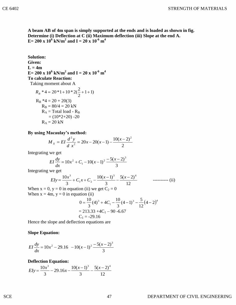
A beam AB of 4m span is simply supported at the ends and is loaded as shown in fig.
Determine (i) Deflection at C (ii) Maximum deflection (iii) Slope at the end A.
E= 200 x 106 kN/m
2 and I = 20 x 10
-6 m
4
Solution:
Given:
L = 4m
E= 200 x 106 kN/m
2 and I = 20 x 10
-6 m
4
To calculate Reaction:
Taking moment about A
)112
2(2*101*204* BR
RB *4 = 20 + 20(3)
RB = 80/4 = 20 kN
RA = Total load - RB
= (10*2+20) -20
RA = 20 kN
By using Macaulay’s method:
2
)2(10)1(2020
2
2
2
xxx
xd
ydEIM X
Integrating we get
3
)2(5)1(1010
32
1
2
xxCx
dx
dyEI
Integrating we get
12
)2(5
3
)1(10
3
10 43
21
3
xxCxC
xEIy ---------- (ii)
When x = 0, y = 0 in equation (ii) we get C2 = 0
When x = 4m, y = 0 in equation (ii)
43
1
3 2412
5)14(
3
104)4(
3
100 C
= 213.33 +4C1 – 90 -6.67
C1 = -29.16
Hence the slope and deflection equations are
Slope Equation:
3
)2(5)1(1016.2910
322
x
xxdx
dyEI
Deflection Equation:
12
)2(5
3
)1(1016.29
3
10 433
xxx
xEIy
CE 6402 STRENGTH OF MATERIALS
SCE 47 DEPARTMENT OF CIVIL ENGINEERING
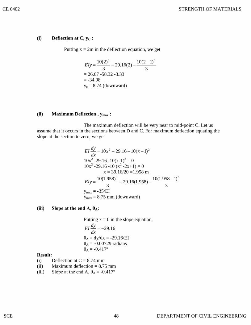
(i) Deflection at C, yC :
Putting x = 2m in the deflection equation, we get
3
)12(10)2(16.29
3
)2(10 33 EIy
= 26.67 -58.32 -3.33
= -34.98
yc = 8.74 (downward)
(ii) Maximum Deflection , ymax :
The maximum deflection will be very near to mid-point C. Let us
assume that it occurs in the sections between D and C. For maximum deflection equating the
slope at the section to zero, we get
22 )1(1016.2910 xx
dx
dyEI
10x2 -29.16 -10(x-1)
2 = 0
10x2 -29.16 -10 (x
2 -2x+1) = 0
x = 39.16/20 =1.958 m
3
)1958.1(10)958.1(16.29
3
)958.1(10 33 EIy
ymax = -35/EI
ymax = 8.75 mm (downward)
(iii) Slope at the end A, θA:
Putting x = 0 in the slope equation,
16.29dx
dyEI
θA = dy/dx = -29.16/EI
θA = -0.00729 radians
θA = -0.417º
Result:
(i) Deflection at C = 8.74 mm
(ii) Maximum deflection = 8.75 mm
(iii) Slope at the end A, θA = -0.417º
CE 6402 STRENGTH OF MATERIALS
SCE 48 DEPARTMENT OF CIVIL ENGINEERING

9. A continuous beam is shown in fig. Draw the BMD indicating salient points.
Solution:
Given:
Length L1 = 4m
Length L2 = 8m
Length L3 = 6m
Udl on BC w = 10 kN/m
Point load W1 = 40 kN
Point load W2 = 40 kN
(i) B.M due to vertical loads:
Consider beam AB, B.M = kNmL
abW30
4
1*3*40
1
1
For beam BC,
B.M = kNmwL
808
)8(10
8
22
For beam CD,
B.M = kNmLW
604
6*40
4
32
(ii) B.M due to support moments:
Let MA, MB, MC, MD be the support moments at A, B, C, D. Since
the end A and D are simply supported MA = MD = 0
By using Clapeyron‟s Equation of Three moments.
For Span AB and BC:
2
22
1
112211
66)(2
L
xa
L
xaLMLLMLM CBA
8
6
4
6)8()84(20 2211 xaxa
MM CB
2MB (12) +8 MC = -1.5a1x1 – 0.75 a2 x2
24 MB +8 MC = -1.5a1x1 – 0.75 a2 x2 ----------- (i)
a1x1 = Moment of area of B.M.D due to point load
= ½*4*30*2/3*3 = 120
a2x2 = Moment of area of B.M.D due to udl
= 2/3 (Base x Altitude) x Base/2
= 2/3 (8*80)*8/2 = 1706.67
CE 6402 STRENGTH OF MATERIALS
SCE 49 DEPARTMENT OF CIVIL ENGINEERING
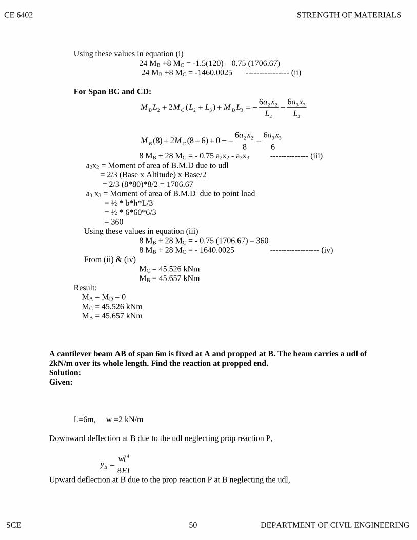
Using these values in equation (i)
24 MB +8 MC = -1.5(120) – 0.75 (1706.67)
24 MB +8 MC = -1460.0025 ---------------- (ii)
For Span BC and CD:
3
33
2
223322
66)(2
L
xa
L
xaLMLLMLM DCB
6
6
8
60)68(2)8( 3322 xaxa
MM CB
8 MB + 28 MC = - 0.75 a2x2 - a3x3 -------------- (iii)
a2x2 = Moment of area of B.M.D due to udl
= 2/3 (Base x Altitude) x Base/2
= 2/3 (8*80)*8/2 = 1706.67
a3 x3 = Moment of area of B.M.D due to point load
= ½ * b*h*L/3
= ½ * 6*60*6/3
= 360
Using these values in equation (iii)
8 MB + 28 MC = - 0.75 (1706.67) – 360
8 MB + 28 MC = - 1640.0025 ------------------ (iv)
From (ii) & (iv)
MC = 45.526 kNm
MB = 45.657 kNm
Result:
MA = MD = 0
MC = 45.526 kNm
MB = 45.657 kNm
A cantilever beam AB of span 6m is fixed at A and propped at B. The beam carries a udl of
2kN/m over its whole length. Find the reaction at propped end.
Solution:
Given:
L=6m, w =2 kN/m
Downward deflection at B due to the udl neglecting prop reaction P,
EI
wlyB
8
4
Upward deflection at B due to the prop reaction P at B neglecting the udl,
CE 6402 STRENGTH OF MATERIALS
SCE 50 DEPARTMENT OF CIVIL ENGINEERING

EI
PlyB
3
3
Upward deflection = Downward deflection
EI
Pl
3
3
EI
wl
8
4
P = 3WL/8 = 3*2*6/8 =4.5 Kn
CE 6402 STRENGTH OF MATERIALS
SCE 51 DEPARTMENT OF CIVIL ENGINEERING
ASSUMPTIONS MADE IN THE EULER’S COLUMN THEORY
3.3 MENTION TH
3.2 STRUTS
3.1 COLUMNS
CHAPTER - III
COLUMNS
Eccentrically loaded short columns – middle third rule – core section – columns of
unsymmetrical sections – (angle channel sections) – Euler‟s theory of long columns – critical
loads for prismatic columns with different end conditions; Rankine-Gordon formula for
eccentrically loaded columns – thick cylinders – compound cylinders.
If the member of the structure is vertical and both of its ends are fixed rigidly while
subjected to axial compressive load, the member is known as column.
Example: A vertical pillar between the roof and floor.
If the member of the structure is not vertical and one (or) both of its ends is Linged (or)
pin jointed, the bar is known as strut.
Example: Connecting rods, piston rods etc,
E STRESSES WHICH ARE RESPONSIBLE FOR COLUMN FAILURE.
i. Direct compressive stresses
ii. Buckling stresses
iii. Combined of direct compressive and buckling stresses.
1. The column is initially perfectly straight and the load is applied axially.
2. The cross-section of the column is uniform throughout its length.
3. The column material is perfectly elastic, homogeneous and isotropic and obeys
Hooke‟s law.
4. The self weight of column is negligible.
1. Both the ends of the column are linged (or pinned)
2. One end is fixed and the other end is free.
3. Both the ends of the column are fixed.
4. One end is fixed and the other is pinned.
3.4 END CONDITIONS OF COLUMNS
CE 6402 STRENGTH OF MATERIALS
SCE 52 DEPARTMENT OF CIVIL ENGINEERING

3.5 EXPLAIN THE FAILURE OF LONG COLUMN
Solution:
A long column of uniform cross-sectional area A and of length l, subjected to an axial
compressive load P, as shown in fig. A column is known as long column if the length of the
column in comparison to its lateral dimensions is very large. Such columns do not fail y
crushing alone, but also by bending (also known buckling)
The load, at which the column just buckles, is known as buckling load and it is less than
the crushing load is less than the crushing load for a long column.
Buckling load is also known as critical just (or) crippling load. The value of buckling
load for long columns are long columns is low whereas for short columns the value of buckling
load is high.
Let
l = length of the long column
p = Load (compressive) at which the column has jus
buckled.
A = Cross-sectional area of he column
e = Maximum bending of the column at the centre.
0 = Stress due to direct load A
P
b = Stress due to bending at the centre of the column
= Z
eP
Where
Z = Section modulus about the axis of bending.
The extreme stresses on the mid-section are given by
Maximum stress = 0 + b
Minimum stress = 0 - b
The column will fail when maximum stress (i.e) 0 + b is more the crushing stress fc.
In case of long column, the direct compressive stresses are negligible as compared to buckling
stresses. Hence very long columns are subjected to buckling stresses.
CE 6402 STRENGTH OF MATERIALS
SCE 53 DEPARTMENT OF CIVIL ENGINEERING

3.7 DERIVE THE EXPRESSION FOR CRIP
3.6 STATE THE ASSUMPTIONS MADE IN THE EULER’S COLUMN THEORY. AND
EXPLAIN THE SIGN CONVENTIONS CONSIDERED IN COLUMNS.
The following are the assumptions made in the Euler’s column theory:
1. The column is initially perfectly straight and the load is applied axially
2. The cross-section of the column is uniform throughout its length.
3. The column material is perfectly elastic, homogeneous and isotropic and
obeys Hooke‟s law.
4. The length of the column is very large as compared to its lateral
dimensions
5. The direct stress is very small as compared to the bending stress
6. The column will fail by buckling alone.
7. The self-weight of column is negligible.
The following are the sign conventions considered in columns:
1. A moment which will tend to bend the column with its convexity towards its
initial centre line is taken as positive.
2. A moment which will tend to bend the column with its concavity towards its
initial center line is taken as negative.
PLING LOAD WHEN THE BOTH ENDS OF
THE COLUMN ARE HINGED
Solution:
Consider a column AB of length L hinged at both its ends A and B carries an axial
crippling load at A.
Consider any section X-X at a distance of x from B.
Let the deflection at X-X is y.
The bending moment at X-X due to the load P, M = yP.
ykEI
Py
dx
yd 2
2
2
Where EI
pk 2
` 02
2
2
ykdx
yd
Solution of this differential equation is
CE 6402 STRENGTH OF MATERIALS
SCE 54 DEPARTMENT OF CIVIL ENGINEERING

3.8 DERIVE THE EXPRESSION FOR BUCKLING LOAD (OR) CRIPPLING LOAD WHEN
kxBkxAy sincos
EI
pxB
EI
pxAy sincos
By using Boundary conditions,
At B, x = 0, y = 0 A = 0
At A, x = l, y = 0
EI
plB sin0
0EI
pSinl
......3,2,,0 EI
pl
Now taking the lest significant value (i.e)
EI
pl ;
22
EI
pl
2
2
l
EIp
`The Euler‟s crippling load for long column with both ends hinged.
2
2
l
EIp
BOTH ENDS OF THE COLUMN ARE FIXED
Solution:
Consider a column AB of length l fixed at both the ends A and B and caries an axial
crippling load P at A due to which buckling occurs. Under the action of the load P the column
will deflect as shown in fig.
Consider any section X-X at a distance x from B.Let the deflection at X-X is y.
CE 6402 STRENGTH OF MATERIALS
SCE 55 DEPARTMENT OF CIVIL ENGINEERING

Due to fixity at the ends, let the moment at A or B is M.
Total moment at XX = M – P.y
Differential equation of the elastic curve is
PyMdx
ydEI
2
2
IE
M
EI
py
dx
yd
2
2
p
p
IE
M
EI
py
dx
yd
2
2
P
M
EI
P
EI
py
dx
yd
2
2
The general solution of the above differential equation is
P
MEIPxBEIPxAy /sin/cos (i)
Where A and B are the integration constant
At, N. x = 0 and y = 0
From (i)
p
MBA 010
p
MA
Differentiating the equation (i) with respect to x,
0./.
EI
PxCos
EI
PBEIPxSin
EI
PA
dx
dy
At the fixed end B, x = 0 and 0dx
dy
0EI
PB
CE 6402 STRENGTH OF MATERIALS
SCE 56 DEPARTMENT OF CIVIL ENGINEERING

Either B = 0 (or) 0EI
P
Since 0EI
P as p 0
B = 0
Subs p
MA and B = 0 in equation (i)
P
M
EI
Px
P
My
.cos
EI
Px
P
My ..cos1
Again at the fixed end A, x = l, y = 0
EIPlCosP
M/.10
........6,4,2,0/. EIPl
Now take the least significant value 2
2. EI
Pl
22 4.
EI
Pl
2
24
l
EIP
The crippling load for long column when both the ends of the column are fixed
2
24
L
EIP
CE 6402 STRENGTH OF MATERIALS
SCE 57 DEPARTMENT OF CIVIL ENGINEERING

3.9 DERIVE THE EXPRESSION FOR CRIPPLING LOAD WHEN COLUMN WITH ONE
END FIXED AND OTHER END HINGED
Solution:
Consider a column AB of length l fixed at B and hinged at A. It carries an axial crippling
load P at A for which the column just buckles.
As here the column AB is fixed at B, there will be some fixed end moment at B. Let it be
M. To balance this fixing moment M, a horizontal push H will be exerted at A.
Consider any section X-X at a distance x from the fixed end B. Let the deflection at xx is
y.
Bending moment at xx = H (l-x) - Py
Differential equation of the elastic curve is,
PyxlHdx
ydEI
2
2
EI
xly
EI
P
dx
yd
142
2
P
p
EI
xlHy
EI
P
dx
yd
2
2
EI
p
EI
xlHy
EI
P
dx
yd
2
2
The general solution of the above different equation is
P
xlH
EI
pxB
EI
pxAy
.sin.cos
Where A and B are the constants of integration. (i)
At B, x = 0, y = 0
From (i) P
HlA
P
H
EI
PB
CE 6402 STRENGTH OF MATERIALS
SCE 58 DEPARTMENT OF CIVIL ENGINEERING

3.10 DERIVE THE EXPRESSION FOR BUCKLING LOAD FOR THE COLUMN WITH
p
EI
P
HB
Again at the end A, x = l, y=0. substitute these values of x, y, A and B in equation (i)
EIPlSinP
EI
P
HEIPlCos
P
Hl/./.0
EIPlCosP
HlEIPlSin
p
EI
P
H/./..
lEIPlEIPl ././.tan
The value of lEIP ./tan in radians has to be such that its tangent is equal to itself. The
only angle whose tangent is equal to itself, is about 4.49 radians.
49.4./ lEIP
22 49.4lEI
P
22 2l
EI
P(approx)
2
22
l
EIP
The crippling load (or) buckling load for the column with one end fixed and one end hinged.
ONE END FIXED AND OTHER END FREE
Solution:
Consider a column AB of length l, fixed at B and free at A, carrying an axial rippling
load P at D de to which it just buckles. The deflected form of the column AB is shown in fig.
Let the new position of A is A1.
Let a be the deflection at the free end. Consider any section X-X at a distance x from B.
2
22
l
EIP
CE 6402 STRENGTH OF MATERIALS
SCE 59 DEPARTMENT OF CIVIL ENGINEERING

Let the deflection at xx is y.
Bending moment due to critical load P at xx,
yaPdx
ydEIM
2
2
pyPadx
ydEI
2
2
EI
pq
EI
py
dx
yd
2
2
The solution of the above differential equation is,
aEI
PxB
EI
PxAy
.sin.cos Where A and B are constants of integration.
At B, x = 0, y = 0
From (i), A = 0
Differentiating the equation (I w.r. to x
EI
PxCos
EI
PB
EI
PxSin
EI
PA
dx
dy..
At the fixed end B, x = 0 and 0dx
dy
EI
PB0
0EI
PAs 0 p
Substitute A = -a and B = 0 in equation (i) we get,
aEI
Pxay
.cos
EI
Pxay ..cos1 (ii)
CE 6402 STRENGTH OF MATERIALS
SCE 60 DEPARTMENT OF CIVIL ENGINEERING

3.11 WRITE THE
At the free end A, x = l, y = a, substitute these values in equation (ii)
EI
Paa ..1cos1
0..1cos
EI
P
2
5,
2
3,
21
EI
P
Now taking the least significant value,
2
1
EI
P
4
12
2
EI
P
2
2
4l
EIP
The crippling load for the columns with one end fixed and other end free.
EXPRESSION FOR CRIPP LING LOAD WHEN THE BOTH ENDS OTHE
COLUMN ARE HINGED
2
2
l
EIP
P = Crippling load
E = Young‟s Modulus
I = Moment of inertia
l = Length of column
2
2
4l
EIP
CE 6402 STRENGTH OF MATERIALS
SCE 61 DEPARTMENT OF CIVIL ENGINEERING

3.16 WRITE THE EQUIVALENT LENGTH (L) OF THE COLUMN IN WHICH BOTH
3.15 EXPLAIN EQUIVALENT LENGTH (OR) EFFECTIVE LENGTH
3.14 EXPRESSION FOR BUCKLING LOAD FOR THE COLUMN WITH ONE FIXED AND
3.13 EXPRESSION FOR CRIPPLING LOAD WHEN COLUMN WITH ONE END FIXED
3.12 EXPRESSION FOR BUCKLING LOAD (OR) CRIPPLING LOAD WHEN BOTH ENDS
OF THE COLUMN ARE FIXED
2
24
L
EIP
P = Crippling load
E = Young‟s Modulus
I = Moment of inertia
l = Length of column
AND OTHER END LINGED
2
22
l
EIP
P = Crippling load
E = Young‟s Modulus
I = Moment of inertia
l = Length of column
OTHER END FREE
2
2
4l
EIP
P = Crippling load
E = Young‟s Modulus
I = Moment of inertia
l = Length of column
If l is actual length of a column, then its equivalent length (or) effective length L may be
obtained by multiplying it with some constant factor C, which depends on the end fixation of the
column (ie) L = C x l.
ENDS HINGED AND WRITE THE CRIPPLING LOAD
Crippling Load 2
2
L
EIP
Equivalent length (L) = Actual length (l)
CE 6402 STRENGTH OF MATERIALS
SCE 62 DEPARTMENT OF CIVIL ENGINEERING

3.17 WRITE THE RELATION BETWEEN EQUIVALENT LENGTH AND ACTUAL
P = Crippling load
E = Young‟s Modulus
I = Moment of inertia
L= Length of column
LENGTH FOR ALL END CONDITIONS OF COLUMN.
Both ends linged L = l Constant = 1
Both ends fixed 2
lL Constant =
2
1
One end fixed and other
end hinged 2
lL Constant =
2
1
One end fixed and other
end free lL 2 Constant = 2
A mild steel tube 4m long, 3cm internal diameter and 4mm thick is used as a strut with
both ends hinged. Find the collapsing load, what will be the crippling load if
i. Both ends are built in?
ii. One end is built –in and one end is free?
Solution:
Given:
Actual length of the mild steel tube, l = 4m = 400 cm
Internal diameter of the tube, d = 3 cm
Thickness of the tube, t = 4mm = 0.4cm.
External diameter of the tube, D = d + 2t
= 3+2(0.4)
= 3.8 cm.
Assuming E for steel = 2 x 10⁶ Kg/cm
2
M.O.I of the column section,
44
64dDI
2438.3
64
I = 6.26 cm 4
CE 6402 STRENGTH OF MATERIALS
SCE 63 DEPARTMENT OF CIVIL ENGINEERING

i. Since the both ends of the tube are hinged, the effective length of the column when
both ends are hinged.
L = l = 400 cm
Euler‟s crippling load 2
2
L
EIPcr
2
62
400
26.6102
.30.772 KgPcr
The required collapsed load = 772.30 Kg.
ii. When both ends of the column are built –in ,
then effective length of the column,
cml
L 2002
400
2
Euler‟s crippling load,
2
2
L
EIPcr
2
62
200
26.6102
Pcr = 3089.19 Kg.
iii. When one end of the column is built in and the other end is free,
effective length of the column, L = 2l
= 2 x 400
= 800 cm
Euler‟s crippling load,
2
2
L
EIPcr
2
62
800
26.6102
Pcr = 193.07 Kg.
CE 6402 STRENGTH OF MATERIALS
SCE 64 DEPARTMENT OF CIVIL ENGINEERING
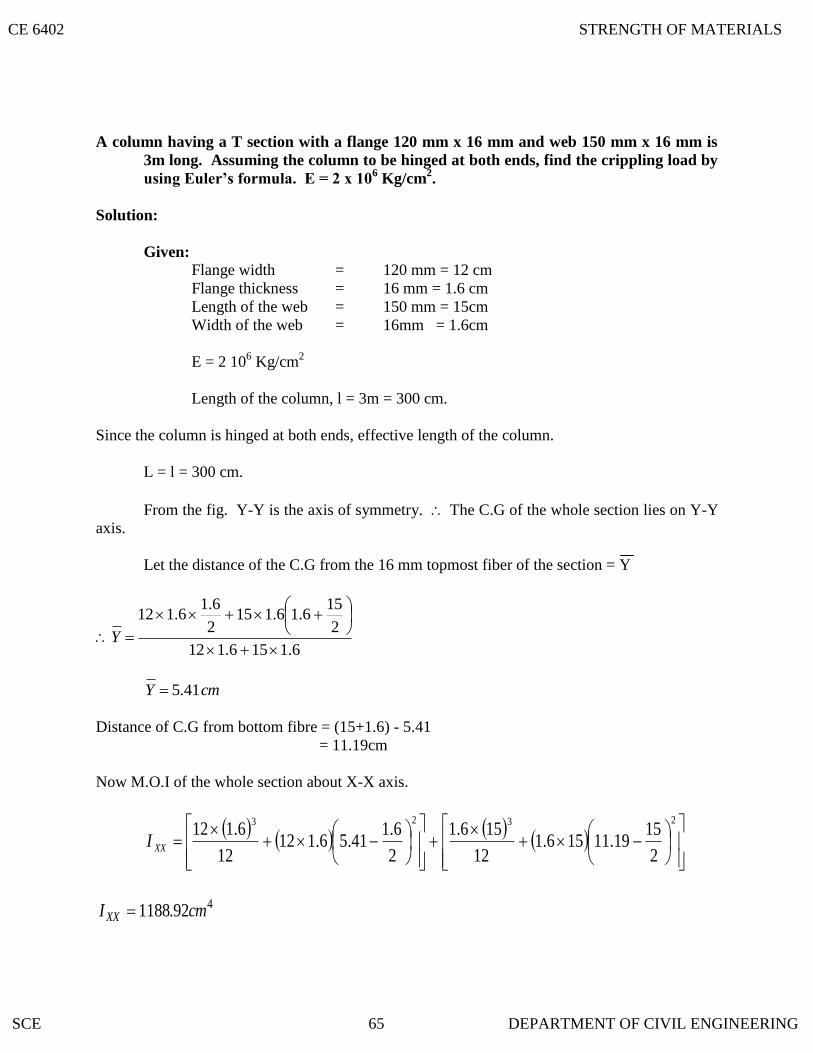
A column having a T section with a flange 120 mm x 16 mm and web 150 mm x 16 mm is
3m long. Assuming the column to be hinged at both ends, find the crippling load by
using Euler’s formula. E = 2 x 10⁶ Kg/cm
2.
Solution:
Given:
Flange width = 120 mm = 12 cm
Flange thickness = 16 mm = 1.6 cm
Length of the web = 150 mm = 15cm
Width of the web = 16mm = 1.6cm
E = 2 106 Kg/cm
2
Length of the column, l = 3m = 300 cm.
Since the column is hinged at both ends, effective length of the column.
L = l = 300 cm.
From the fig. Y-Y is the axis of symmetry. The C.G of the whole section lies on Y-Y
axis.
Let the distance of the C.G from the 16 mm topmost fiber of the section = Y
6.1156.112
2
156.16.115
2
6.16.112
Y
cmY 41.5
Distance of C.G from bottom fibre = (15+1.6) - 5.41
= 11.19cm
Now M.O.I of the whole section about X-X axis.
2323
2
1519.11156.1
12
156.1
2
6.141.56.112
12
6.112XXI
492.1188 cmIXX
CE 6402 STRENGTH OF MATERIALS
SCE 65 DEPARTMENT OF CIVIL ENGINEERING

M.I of the whole section about Y-Y axis
433
52.23512
10615
12
126.1cmI yy
4
min 52.235 cmI
Euler‟s Crippling load,
2
2
L
EIPcr
2
62
300
52.235102
; .32.51655 KgPcr
A steel bar of solid circular cross-section is 50 mm in diameter. The bar is pinned at both
ends and subjected to axial compression. If the limit of proportionality of the material is
210 MPa and E = 200 GPa, determine the m minimum length to which Euler’s
formula is valid. Also determine the value of Euler’s buckling load if the column has this
minimum length.
Solution:
Given,
Dia of solid circular cross-section, d = 50 mm
Stress at proportional limit, f = 210 Mpa
= 210 N/mm2
Young‟s Modulus, E = 200 GPa = 200 x 10 3 N/mm
2
Area of cross –section, 2249.196350
4mmA
Least moment of inertia of the column section,
4341079.6.350
64mmI
Least radius of gyration,
243
2 25.1565049.1963
1079.306mm
A
Ik
The bar is pinned at both ends,
Effective length, L = Actual length, l
CE 6402 STRENGTH OF MATERIALS
SCE 66 DEPARTMENT OF CIVIL ENGINEERING
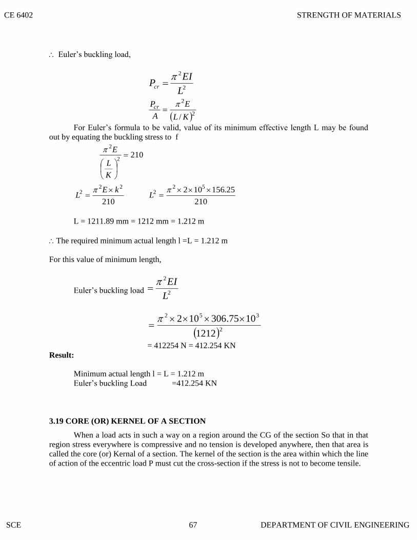
3.19 CORE (OR) KERNEL OF A SECTION
Euler‟s buckling load,
2
2
L
EIPcr
2
2
/ KL
E
A
Pcr
For Euler‟s formula to be valid, value of its minimum effective length L may be found
out by equating the buckling stress to f
210
2
2
K
L
E
210
222 kE
L
210
25.156102 522
L
L = 1211.89 mm = 1212 mm = 1.212 m
The required minimum actual length l =L = 1.212 m
For this value of minimum length,
Euler‟s buckling load 2
2
L
EI
2
352
1212
1075.306102
= 412254 N = 412.254 KN
Result:
Minimum actual length l = L = 1.212 m
Euler‟s buckling Load =412.254 KN
When a load acts in such a way on a region around the CG of the section So that in that
region stress everywhere is compressive and no tension is developed anywhere, then that area is
called the core (or) Kernal of a section. The kernel of the section is the area within which the line
of action of the eccentric load P must cut the cross-section if the stress is not to become tensile.
CE 6402 STRENGTH OF MATERIALS
SCE 67 DEPARTMENT OF CIVIL ENGINEERING

3.23 A STEEL COLUMN IS OF LENGTH 8M AND DIAMETER
3.21 DERIVE THE EXPRESSION FOR CORE OF A SOLID CIRCULAR SECTION OF
3.20 DERIVE THE EXPRESSION FOR CORE OF A RECTANGULAR SECTION
The limit of eccentricity of a rectangular section b x d on either side of XX axis (or) YY
axis is d/6 to avoid tension at the base core of the rectangular section.
Core of the rectangular section = Area of the shaded portion
632
12
db
18
bd
DIAMETER D
The limit of eccentricity on either side of both XX (or) YY axis = D/8 to avoid tension of
the base.
Core of the circular section = Area of the shaded portion
28/D
64
2D
600 MM WITH BOTH
ENDS HINGED. DETERMINE THE CRIPPLING LOAD BY EULER’S
FORMULA. Take 5101.2 E N/mm
2.
49441036.6600
6464mmdI
Since the column is hinged at the both ends,
Equivalent length L = l
2
2
L
EIPcr
2
952
8000
1036.6101.2
N81006.2
CE 6402 STRENGTH OF MATERIALS
SCE 68 DEPARTMENT OF CIVIL ENGINEERING

WRITE THE RANKINE’S FORMULA FOR E
3.25 WRITE THE RANKIN
STATE THE LIMITATIONS OF EULER’S FORMULA
3.24 SLENDERNESS RATIO
It is defined as the ratio of the effective length of the column (L) to the least radius of
gyration of its cross –section (K) (i.e) the ratio of K
L is known as slenderness ratio.
Slenderness ratio = K
L
a. Euler‟s formula is applicable when the slenderness ratio is greater than or equal to 80
b. Euler‟s formula is applicable only for long column
c. Euler‟s formula is thus unsuitable when the slenderness ratio is less than a certain
value.
E’S FORMULA FOR COLUMNS
2
1
K
L
AfP c
K = Least radius of gyration A
I
P = Crippling load
A = Area of the column
fc = Constant value depends upon the material.
= Rankine‟s constant E
fc
2
CCENTRIC COLUMN
2
211
k
L
k
ey
AfP
c
c
K = Least radius of gyration A
I
P = Crippling load
A = Area of the column
fc = Constant value depends upon the material.
CE 6402 STRENGTH OF MATERIALS
SCE 69 DEPARTMENT OF CIVIL ENGINEERING

= Rankine‟s constant E
fc
2
Explain Rankine’s Formula and Derive the Rankine’s formula for both short and long
column.
Solution:
Rankine’s Formula:
Euler‟s formula gives correct results only for long columns, which fail mainly due to
buckling. Whereas Rankine‟s devised an empirical formula base don practical experiments for
determining the crippling or critical load which is applicable to all columns irrespective of
whether they a short or long.
If P is the crippling load by Rankine‟s formula.
Pc is the crushing load of the column material
PE is the crippling load by Euler‟s formula.
Then the Empirical formula devised by Rankine known as Rankine‟s formula stand as:
Ee PPP
111
For a short column, if the effective length is small, the value of PE will be very high and
the value of EP
1 will be very small as compared to
CP
1and is negligible.
For the short column, (i.e) P = PC
Thus for the short column, value of crippling load by Rankine is more or less equal to the
value of crushing load:
For long column having higher effective length, the value of PE is small and EP
1will
be large enough in comparison to CP
1. So
CP
1 is ignored.
cPP
11
CE 6402 STRENGTH OF MATERIALS
SCE 70 DEPARTMENT OF CIVIL ENGINEERING

For the long column, CP
1
EP
1 (i.e) p PE
Thus for the long column the value of crippling load by Rankine is more or less equal to
the value of crippling load by Euler.
Ec PPP
111
Ec
cE
PP
PP
P
1
cE
Ec
PP
PPp
;
E
c
c
P
P
Pp
1
Substitute the value of Pc = fc A and 2
2
L
EIPE
in the above equation,
22 /1
LEI
Af
Afp
c
c
Where,
fc = Ultimate crushing stress of the column material.
A = Cross-sectional are of the column
L = Effective length of the column
I = Ak2
Where k = Least radius of gyration.
22
2
22 1/
1EAk
LAf
Af
LEI
Af
Afp
c
c
c
c
2
1
K
L
Afp c
where = Rankine‟s constant E
f c
2
CE 6402 STRENGTH OF MATERIALS
SCE 71 DEPARTMENT OF CIVIL ENGINEERING

P = 2
/1 kL
LoadCrushing
When Rankine‟s constant is not given then find
E
f c
2
The following table shows the value of fc and for different materials.
Material fc N/mm2
E
f c
2
Wrought iron 250 9000
1
Cast iron 550 1600
1
Mild steel 320 7500
1
Timber 50 750
1
A rolled steel joist ISMB 300 is to be used a column of 3 meters length with both ends fixed.
Find the safe axial load on the column. Take factor of safety 3, fc = 320 N/mm2
and7500
1 . Properties of the column section.
Area = 5626 mm2, IXX = 8.603 x 10
7 mm
4
Iyy =4.539 x 10
7 mm
4
Solution:
Given: Length of the column, l = 3m = 3000 mm
Factor of safety = 3
fc = 320 N/mm2,
7500
1
Area, A = 5626 mm2
IXX = 8.603 x 107 mm
4
Iyy =4.539 x 10
7 mm
4
The column is fixed at both the ends,
CE 6402 STRENGTH OF MATERIALS
SCE 72 DEPARTMENT OF CIVIL ENGINEERING

Effective length, mml
L 15002
3000
2
Since Iyy is less then Ixx, The column section,
47
min 10539.4 mmIII yy
Least radius of gyration of the column section,
mmA
IK 82.89
5626
10539.4 7
Crippling load as given by Rakine‟s formula,
22
82.89
1500
7500
11
5626320
1
K
L
Afp c
cr
Pcr = 1343522.38 N
Allowing factor of safety 3,
Safe load = safetyofFactor
LoadCrippling
N79.4478403
38.1343522
Result:
i. Crippling Load (Pcr) = 1343522.38 N
ii. Safe load =447840.79N
A built up column consisting of rolled steel beam ISWB 300 with two plates 200 mm x 10
mm connected at the top and bottom flanges. Calculate the safe load the column
carry, if the length is 3m and both ends are fixed. Take factor of safety 3 fc = 320
N/mm2 and
7500
1
Take properties of joist: A = 6133 mm2
IXX = 9821.6 x 104 mm
4 ; Iyy = 990.1 x 10
4 mm
4
CE 6402 STRENGTH OF MATERIALS
SCE 73 DEPARTMENT OF CIVIL ENGINEERING

Solution:
Given:
Length of the built up column, l = 3m = 3000 mm
Factor of safety = 3
fc =320 N/mm2
7500
1
Sectional area of the built up column,
2101331020026133 mmA
Moment of inertia of the built up column section abut xx axis,
23
4 1551020012
102002106.9821XXI
= 1.94 x 108 mm
4
Moment of inertia of the built up column section abut YY axis,
12
200102101.990
34
YYI
= 0.23 x 108 mm
4
Since Iyy is less than Ixx , The column will tend to buckle about Y-Y axis.
Least moment of inertia of the column section,
48
min 1023.0 mmIII YY
The column is fixed at both ends.
Effective length,
mml
L 15002
3000
2
Least radius of gyration o the column section,
mmA
JK 64.47
10133
1023.0 8
CE 6402 STRENGTH OF MATERIALS
SCE 74 DEPARTMENT OF CIVIL ENGINEERING

Crippling load as given by Rankine‟s formula,
22
64.47
1500
7500
11
10133320
1
K
L
Afp c
cr
= 2864023.3 N
Safe load = N43.9546743
3.2864023
Result:
i. Crippling load = 2864023.3 N
ii. Safe load = 954674.43 N
Derive Rankine’s and Euler formula for long columns under long columns under Eccentric
Loading?
i. Rankine’s formula:
Consider a short column subjected to an eccentric load P with an eccentricity e form the
axis.
Maximum stress = Direct Stress + Bending stress
Z
M
A
Pf c
y
IZ
2
..
Ak
yep
A
P c 2AkI
A
Ik
where
A = Sectional are of the column
Z = Sectional modulus of the column
yc = Distance of extreme fibre from N.A
k = Least radius of gyration.
Crippling load
Factor of safety
CE 6402 STRENGTH OF MATERIALS
SCE 75 DEPARTMENT OF CIVIL ENGINEERING

21
k
ey
A
Pf c
c
Where
21
k
ey c
is the reduction factor for eccentricity of loading.
For long column, loaded with axial loading, the crippling load,
2
1
K
L
AfP c
Where
2
1K
L is the reduction factor for buckling of long column.
Hence for a long column loaded with eccentric loading, the safe load,
ii. Euler‟s formula
Maximum stress n the column = Direct stress + Bending stress
Z
lEIPeP
A
P 2/sec
Hence, the maximum stress induced in the column having both ends hinged and an
eccentricity of e is
2/sec
lEIP
Z
Pe
A
P
Eccentric load,
21
k
ey
AfP
c
c
2
211
K
L
K
ey
AfP
c
c
CE 6402 STRENGTH OF MATERIALS
SCE 76 DEPARTMENT OF CIVIL ENGINEERING

The maximum stress induced in the column with other end conditions are determined by
changing the length in terms of effective length.
A column of circular section has 150 mm dia and 3m length. Both ends of the column are
fixed. The column carries a load of 100 KN at an eccentricity of 15 mm from the
geometrical axis of the column. Find the maximum compressive stress in the
column section. Find also the maximum permissible eccentricity to avoid tension in
the column section. E = 1 x 10⁵ N/mm
2
Solution:
Given,
Diameter of the column, D = 150 mm
Actual length of the column, l = 3m = 3000 mm
Load on the column, P = 100 KN = 1000 x 103 N
E = 1 x 10⁵ N/mm
2
Eccentricity, e = 15 mm
Area of the column section 4
2DA
2150
4
= 17671 mm2
Moment of inertia of the column section N.A.,
44 1506464
DI
= 24.85 x 106 mm
4
Section modulus,
2/D
I
y
IZ
= 3
6
331339
2
150
1085.24mm
Both the ends of the column 2 are fixed.
Effective length of the column, mml
L 15002
3000
2
Now, the angle
CE 6402 STRENGTH OF MATERIALS
SCE 77 DEPARTMENT OF CIVIL ENGINEERING

State the assumptions and derive Lame’s Theory?
2
1500
1085.24101
10100
2/
65
3
LEIP
= 0.1504 rad = 8.61 o
Maximum compressive stress,
2/sec
LEIP
Z
eP
A
P
331339
61.8sec1510100
17671
10100 33 o
= 10.22 N/mm2
To avoid tension we know,
Z
M
A
P
Z
ep
A
P o61.8.sec
331339
61.8.sec10100
17671
10100 33 oe
e = 18.50 mm
Result:
i. Maximum compressive stress = 10.22 N/mm2
ii. Maximum eccentricity = 18.50 mm
1. The assumptions involved in Lame’s Theory.
i. The material of the shell is homogenous and isotropic
ii. Plane sections normal to the longitudinal axis of the cylinder remain plane
after the application of internal pressure.
iii. All the fibres of the material expand (or) contract independently without being
constrained by their adjacent fibres.
2 Derivation of Lame’s Theory
Consider a thick cylinder
CE 6402 STRENGTH OF MATERIALS
SCE 78 DEPARTMENT OF CIVIL ENGINEERING

Let
rc = Inner radius of the cylinder
r0 = Outer radius of the cylinder
Pi = Internal radial pressure
Po = External radial pressure
L = Length of the cylinder
f2 = Longitudinal stress.
Lame‟s Equation:
axx pf 2
axx
bP
2
aax
bf x 2
2
ax
bf x
2
where
fx = hoop stress induced in the ring.
px = Internal radial pressure in the fig.
Px + dPx = External radial pressure in the ring.
The values of the two constants a and to b are found out using the following boundary
conditions:
i. Since the internal radial pressure is Pi,
At x = ri, Px = Pi
ii. Since the external radial pressure is P0
,
At x = r0, Px = P0
CE 6402 STRENGTH OF MATERIALS
SCE 79 DEPARTMENT OF CIVIL ENGINEERING

STATE THE ASSUMPTIONS INVOLVED IN LAME’S THEORY
3.27 MIDDLE THIRD RULE
3.26 THICK CYLINDER
If the ratio of thickness of the internal diameter of a cylindrical or spherical shell exceeds
1/20, it is termed as a thick shell.
The hoop stress developed in a thick shell varies from a maximum value at the inner
circumference to a minimum value at the outer circumference.
Thickness > 1/20
j. The material of the shell is Homogeneous and isotropic.
ii. Plane section normal to the longitudinal axis of the cylinder remains plane after
the application of internal pressure.
iii. All the fibers of the material expand (or) contact independently without being
constrained by there adjacent fibers.
In rectangular sections, the eccentricity „e‟ must be less than or equal to b/6. Hence the
greatest eccentricity of the load is b/6 form the axis Y-Y and with respect to axis X –X1 the
eccentricity does not exceed d/6. Hence the load may be applied with in the middle third of the
base (or) Middle d/3.
A thick steel cylinder having an internal diameter of 100 mm an external diameter of 200
mm is subjected to an internal pressure of 55 M pa and an external pressure of 7
Mpa. Find the maximum hoop stress.
Solution:
Given,
Inner radius of the cylinder, mmri 502
100
Outer radius of the cylinder, mmro 1002
200
Internal pressure, Pi = 55 Mpa
External pressure, P0 = 7 Mpa
In the hoop stress and radial stress in the cylinder at a distance of x from the centre is fx
and px respectively, using Lame‟s equations,
ax
bf x
2 (i)
ax
bPx
2 (ii)
CE 6402 STRENGTH OF MATERIALS
SCE 80 DEPARTMENT OF CIVIL ENGINEERING

where a and b are constants,
Now by equation, at x = 50 mm, Px = 55 MPa (Boundary condition)
Using these boundary condition in equation (ii)
ax
bPx
2
ab
2
5055 (iii)
Then x = 100 mm, px = 7 Mpa
Using these boundary condition is equation (ii)
ab
2100
7 (iv)
Solving (iii) & (iv)
7100/2
ab
5550/2
ab
(- ) (+)
10000
3b = - 48
Substitute a & b in equation (i)
9160000
2
xf x
The value of fx is maximum when x is minimum
Thus fx is maximum for x = ri = 50 mm
Maximum hoop stress
950
1600002
= 73 Mpa (tensile)
Result:
b = 160000
a = 9
CE 6402 STRENGTH OF MATERIALS
SCE 81 DEPARTMENT OF CIVIL ENGINEERING

Maximum hoop stress = 73 MPa (tensile)
A cast iron pipe has 200 mm internal diameter and 50 mm metal thickness. It carries water
under a pressure of 5 N/mm2. Find the maximum and minimum intensities of
circumferential stress. Also sketch the distribution of circumferential stress and
radial stress across the section.
Solution:
Given:
Internal diameter, di = 200 mm
Wall thickness, t = 50 mm
Internal pressure, Pi = 5 N/mm2
External pressure, P0 = 0.
Internal radius mmdi
ri 1002
200
2
External radius mmtrr i 150501000
Let fx and Px be the circumferential stress and radial stress at a distance of x from the centre of
the pipe respectively.
Using Lame‟s equations,
ax
bf x
2 (i)
ax
bp x
2 (ii)
where, a & b are arbitrary constants.
Now at x = 100 mm, Px = 5 N/mm2
At x = 150 mm, Px = 0
Using boundary condition is (ii)
ab
2
1005 (ii)
ab
2
1500 (iv)
By solving (iii) & (iv) a = 4 ; b = 90000
CE 6402 STRENGTH OF MATERIALS
SCE 82 DEPARTMENT OF CIVIL ENGINEERING

,490000
2
xf x ,4
900002
x
Px
Putting x = 100 mm, maxi circumferential stress.
tensilemmNf x
2
2/134
100
90000
Putting x = 150 mm, mini circumferential stress.
tensilemmNf x
2
2/84
150
90000
Explain the stresses in compound thick cylinders.
Solution: Consider a compound thick cylinder as shown in fig.
Let,
r1 = Inner radius of the compound cylinder
r2 = Radius at the junction of the two cylinders
r3 = Outer radius of the compound cylinder
When one cylinder is shrunk over the other, thinner cylinder is under compression and
the outer cylinder is under tension. Due to fluid pressure inside the cylinder, hoop stress will
develop. The resultant hoop stress in the compound stress is that algebraic sum of the hoop
stress due to initial shrinkage and that due to fluid pressure.
a. Stresses due to initial shrinkage:
Applying Lame‟s Equations for the outer cylinder,
12
1 ax
bPx
12
1 ax
bf x
At x = r3, Px = 0 and at x = r2, px = p
Applying Lame‟s Equations for the inner cylinder
CE 6402 STRENGTH OF MATERIALS
SCE 83 DEPARTMENT OF CIVIL ENGINEERING

22
2 ax
bPx
22
2 ax
bf x
At x = r2, Px = p and at x = r3, px = 0
b. Stresses due to Internal fluid pressure.
To find the stress in the compound cylinder due to internal fluid pressure alone, the inner
and outer cylinders will be considered together as one thick shell. Now applying Lame‟s
Equation,
Ax
BPx
2
Ax
Bf x
2
At x = r1, Px = pf ( Pf being the internal fluid pressure)
At x = r3, px = 0
The resultant hoop stress is the algebraic sum of the hoop stress due to shrinking and due
internal fluid pressure.
A compound cylinder is composed of a tube of 250 mm internal diameter at 25 mm wall
thickness. It is shrunk on to a tube of 200 mm internal diameter. The radial
pressure at the junction is 8 N/mm2.
Find the variation of hoop stress across the
wall of the compound cylinder, if it is under an internal fluid pressure of 60 N/mm2
Solution:
Given: Internal diameter of the outer tube, d1 = 250 mm
Wall thickness of the outer tuber , t = 25 mm
Internal diameter of the inner tube , d2 = 200 mm
Radial pressure at the junction P = 8 N/mm2
Internal fluid pressure within the cylinder Pf = 60 N/mm2
External radius of the compound cylinder,
2
212
tdr
CE 6402 STRENGTH OF MATERIALS
SCE 84 DEPARTMENT OF CIVIL ENGINEERING

mm1502522502
1
Internal radius of the compound cylinder,
mmd
r 1002
200
2
21
Radius at the junction, mmd
r 1252
250
2
11
Let the radial stress and hoop stress at a distance of x from the centre of the cylinder be
px and fx respectively.
i. Hoop stresses due to shrinking of the outer and inner cylinders before fluid
pressure is admitted.
a. Four outer cylinder:
Applying Lame‟s Equation
12
1 ax
bPx (i)
12
1 ax
bf x (ii)
Where a1 and b1 are arbitrary constants for the outer cylinder.
Now at x = 150 mm, Px = 0
X = 125 mm, Px = 8 N/mm2
12
1
150a
bo (iii)
12
1
1258 a
b (iv)
Solving equation (iii) & (iv) a1 = 18 ; b1 = 409091
18409091
2
xf x (v)
Putting x = 150 mm in the above equation stress at the outer surface,
2
2/3618
150
409091mmNf x (tensile)
Again putting x = 125 mm in equation (v), stress at junction,
CE 6402 STRENGTH OF MATERIALS
SCE 85 DEPARTMENT OF CIVIL ENGINEERING

2
2/4418
125
409091mmNf x (tensile)
b). For inner cylinder: Applying Lame‟s Equation with usual Notations.
22
2 ax
bPx (iv)
22
2 ax
bf x (v)
Now at x = 125 mm, Px = 8 N/mm2
x =100 mm, Px = 0
22
2
1258 a
b (vi)
22
2
100a
bo (vii)
By solving (vi) & (vii) a2 = -22
b2 = -222222
2
2/2.4422
100
222222mmNf x
(comp)
2
2/2.3622
125
222222mmNf x
(comp)
iii. Hoop stresses due to internal fluid pressure alone for the compound cylinder:
In this case, the two tubes will be taken as a single thick cylinder. Applying Lame‟s
equations with usual notations.
Ax
BPx
2 (viii)
Ax
Bf x
2 (ix)
At x = 150 mm, Px = 0
CE 6402 STRENGTH OF MATERIALS
SCE 86 DEPARTMENT OF CIVIL ENGINEERING

x = 100 mm, Px = pf = 60 N/mm2
From Equation (viii)
AB
O 2
150 (x)
AB
2
10060 (xi)
By solving (x) & (xi)
A = 133, B = 3 x 10⁶
1331032
6
x
f x
Putting x = 150 mm, hoop stress at the outer surface
2
2
6
/266133150
103mmNf x
(Tensile)
Again putting x = 125 mm, hoop stress at the junction
TensilemmNf x2
2
6
/325133125
103
Putting x = 100 mm, hoop stress at the inner surface
TensilemmNf x2
2
6
/433133100
103
iii. Resultant hoop stress (shrinkage +Fluid pressure):
a. Outer cylinder
Resultant hoop stress at the outer surface = 36 + 266
= 302 N/ mm2 (Tensile)
Resultant hoop stress at the junction = 44 + 325 = 369 N/mm2 (tensile)
b. Inner cylinder;
Resultant hoop stress at the inner face = - 44.2 + 433
CE 6402 STRENGTH OF MATERIALS
SCE 87 DEPARTMENT OF CIVIL ENGINEERING

= 388.8 N/mm2 (Tensile)
Resultant hoop stress at the junction = - 36.2 + 325
= 288.8 N/mm2
(Tensile)
A column with alone end hinged and the other end fixed has a length of 5m and a hollow
circular cross section of outer diameter 100 mm and wall thickness 10 mm. If E = 1.60
x 105 N/mm
2 and crushing strength
2
0 /350 mmN , Find the load that the column may
carry with a factor of safety of 2.5 according to Euler theory and Rankine – Gordon
theory. If the column is hinged on both ends, find the safe load according to the two
theories. (April/May 2003)
Solution:
Given: L = 5 m = 5000 mm
Outer diameter D = 100 mm
Inner diameter d = D-2t = 100 – 2 (10) = 80 mm
Thickness = 10 mm
I = 1.60 x 10⁵ N/mm
2
2
0 /350 mmN
f = 2.5
i. Calculation of load by Euler’s Theory:
Column with one end fixed and other end hinged.
2
22
L
EIP
mm
lL 60.3536
2
5000
2
2
52
06.3536
1060.114.32 IP
44
64dDI
44 8010064
4096000010000000064
I = 28.96 x 105 mm
4
CE 6402 STRENGTH OF MATERIALS
SCE 88 DEPARTMENT OF CIVIL ENGINEERING

14.12503716
1096.281060.114.32 552
P
p = 73.074 x 10³ N
ii. Calculation of load by Rankine-Gordon Theory:
Rankine‟s Constant 7500
1a (assume the column material is mild steel.)
2
1
K
La
Afp c
K = lest radius of Gyration
01.322826
1096.28 5
A
I
22 801004
A
6400100004
fc = c
= 2826 mm2
2
01.32
06.3536
7500
11
26.28350
P
036.122031033.1
9891004
P
NP 41094.60
iii. Both ends are hinged
Euler‟s theory
2
2
L
EIP
L = l
2
552
5000
1096.281060.114.3
CE 6402 STRENGTH OF MATERIALS
SCE 89 DEPARTMENT OF CIVIL ENGINEERING
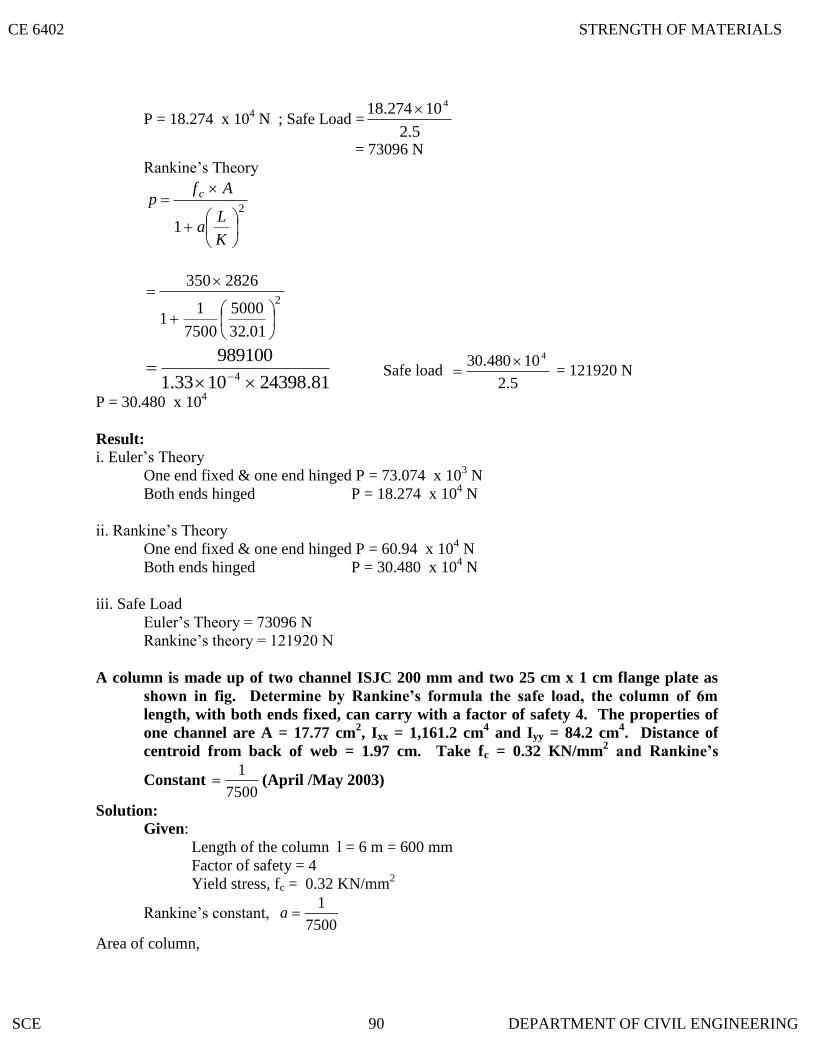
P = 18.274 x 10⁴ N ; Safe Load =
5.2
10274.18 4
= 73096 N
Rankine‟s Theory
2
1
K
La
Afp c
2
01.32
5000
7500
11
2826350
81.243981033.1
9891004
Safe load
5.2
10480.30 4 = 121920 N
P = 30.480 x 10⁴
Result: i. Euler‟s Theory
One end fixed & one end hinged P = 73.074 x 10³ N
Both ends hinged P = 18.274 x 10⁴ N
ii. Rankine‟s Theory
One end fixed & one end hinged P = 60.94 x 10⁴ N
Both ends hinged P = 30.480 x 10⁴ N
iii. Safe Load
Euler‟s Theory = 73096 N
Rankine‟s theory = 121920 N
A column is made up of two channel ISJC 200 mm and two 25 cm x 1 cm flange plate as
shown in fig. Determine by Rankine’s formula the safe load, the column of 6m
length, with both ends fixed, can carry with a factor of safety 4. The properties of
one channel are A = 17.77 cm2, Ixx = 1,161.2 cm
4 and Iyy = 84.2 cm
4. Distance of
centroid from back of web = 1.97 cm. Take fc = 0.32 KN/mm2 and Rankine’s
Constant 7500
1 (April /May 2003)
Solution: Given:
Length of the column l = 6 m = 600 mm
Factor of safety = 4
Yield stress, fc = 0.32 KN/mm2
Rankine‟s constant, 7500
1a
Area of column,
CE 6402 STRENGTH OF MATERIALS
SCE 90 DEPARTMENT OF CIVIL ENGINEERING
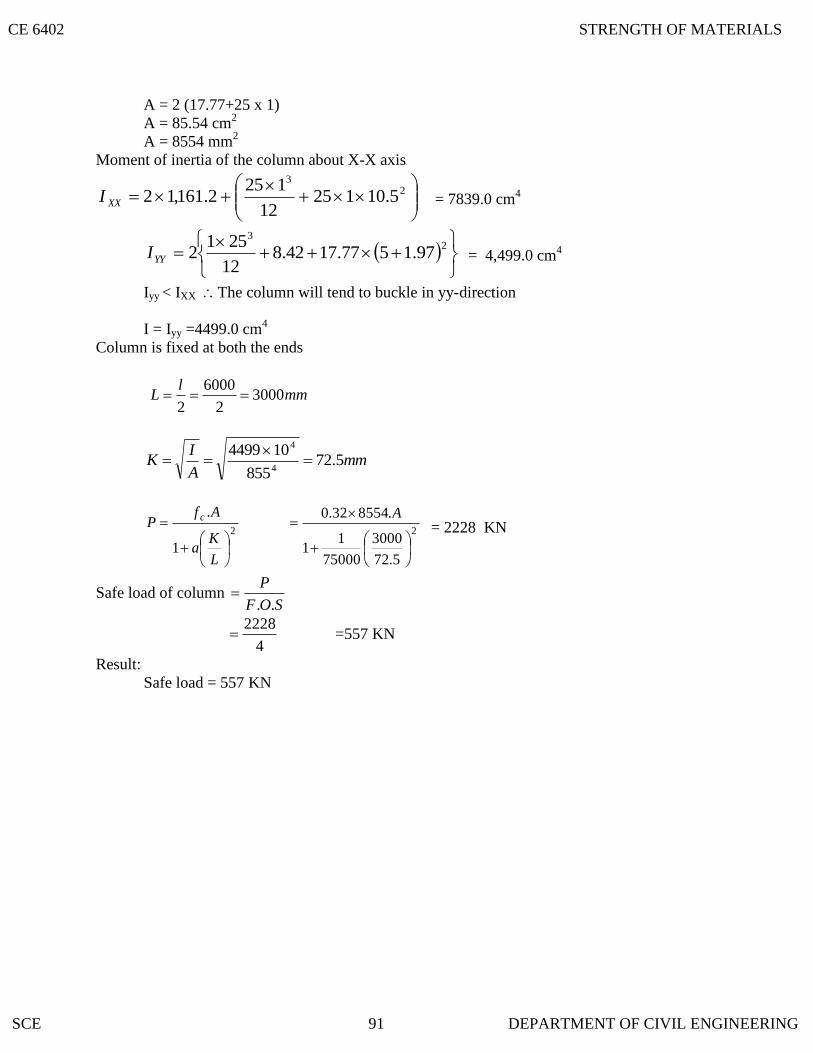
A = 2 (17.77+25 x 1)
A = 85.54 cm2
A = 8554 mm2
Moment of inertia of the column about X-X axis
2
3
5.1012512
1252.161,12XXI = 7839.0 cm
4
2
3
97.1577.1742.812
2512YYI = 4,499.0 cm
4
Iyy < IXX The column will tend to buckle in yy-direction
I = Iyy =4499.0 cm4
Column is fixed at both the ends
mml
L 30002
6000
2
mmA
IK 5.72
855
1044994
4
2
1
.
L
Ka
AfP c
2
5.72
3000
75000
11
.855432.0
A = 2228 KN
Safe load of column SOF
P
..
4
2228 =557 KN
Result:
Safe load = 557 KN
CE 6402 STRENGTH OF MATERIALS
SCE 91 DEPARTMENT OF CIVIL ENGINEERING

4.4 DEVIATOR STRESS TENSOR
4.3 SPHERICAL TENSOR
4.2 PRINCIPAL PLANES
4.1 STRESS
CHAPTER- IV
STATE OF STRESS IN THREE DIMENSIONS
Spherical and deviatory components of stress tensor- determination of principal of
principal stresses and principal planes – volumetric strain- dilation and distortion – Theories of
failure – principal stress dilatation. Principal strain – shear stress - strain energy and distortion
energy theories - application in analysis of stress. Load carrying capacity and design of members
– interaction problems and interaction curves – residual stresses.
When a certain system of external forces act on a body then the body offers resistance to
these forces. This internal resistance offered by the body per unit area is called the stress
induced in the body.
The plane in which the shear stress is zero is called principal planes. The plane which is
independent of shear stress is known as principal plane.
0
0
m
iiij
0
0
m
m
0
0
It is also known as hydrostatic stress tensor
zyxm 3
1
m is the mean stress.
xz
xy
mx
ij
1
yz
my
xy
l
l
mz
yz
xz
CE 6402 STRENGTH OF MATERIALS
SCE 92 DEPARTMENT OF CIVIL ENGINEERING

4.5 THE STRESS COMPONENTS AT A POINT ARE GIVEN BY THE FOLLOWING
ARRAY
6
5
10
10
8
5
6
10
6
Mpa
Calculate the principal stress and principal planes.
Solution:
The principal stresses are the roots of the cubic equation
0322
13 III (1)
where,
zyxI 1
222
2 zxzyyxxzzyyxI
xzyzxyxyzxzyyzxzyxI 22223
are three stress invariants
The stress tensor
zx
yx
x
ij
.
zy
y
xy
z
yz
xz
By comparing stress tensor and the given away,
zyxI 1
= 10 + 8 +6 =24
xzyzxyxzzyyxI 2222
= (10 x 8) + (8 x 6) + (6 x 10) - (5)2 – (10)
2 – (6)
2
=80 + 48 + 60 - 25 – 100 -36
=27
xzyzxyxyzxzyyzxzyxI 22223
= 10 x 8 x 6 -10 (10)2 -8 (6 )
2 - 6 (5)
2 + 2(5) (10) (6)
CE 6402 STRENGTH OF MATERIALS
SCE 93 DEPARTMENT OF CIVIL ENGINEERING
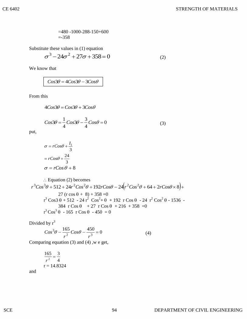
=480 -1000-288-150+600
=-358
Substitute these values in (1) equation
03582724 23 (2)
We know that
From this
CosCosCos 3334
04
33
4
13 CosCosCos (3)
put,
3
1IrCos
3
24 rCos
8 rCos
Equation (2) becomes
82642419224512 222233 rCosCosrrCosCosrCosr
27 (r cos + 8) + 358 =0
r3 Cos3 + 512 - 24 r
2 Cos
2+
+ 192 r Cos - 24 r
2 Cos
2 - 1536 -
384 r Cos + 27 r Cos + 216 + 358 =0
r3
Cos3 - 165 r Cos - 450 = 0
Divided by r3
0450165
32
3 r
Cosr
Cos (4)
Comparing equation (3) and (4) ,w e get,
4
31652
r
r = 14.8324
and
CosCosCos 3343
CE 6402 STRENGTH OF MATERIALS
SCE 94 DEPARTMENT OF CIVIL ENGINEERING

4.6 OBTAIN THE PRINCIPAL STRESSES AND THE RELATED DIRECTION COSINES
4
34503
Cos
r
3
8324.14
44503
Cos
Cos 3 = 0.551618
1 = 18.84o
2 = 1 + 120
2 = 138.84o
3 = 2 +120
3 = 258.84o
1 = r Cos 1 + 8
= 14.8324 Cos (18.84o) + 8
1 = 22.04 MPa
= 14.8324 Cos 138. 84o + 8
= - 3.17 MPa
3 = r cos 3 + 8
= 14.8324 Cos 258. 84o + 8
= 5.13 MPa
Result:
1 = 18.84 o 1 = 22.04 MPa
2 = 138.84 o 2 = -3.17 MPa
3 = 258.84 o 3 = 5.13 MPa
FOR THE FOLLOWING STATE OF STRESS
6
4
.3
5
2
4
MPa
1
5
6
Solution:
CE 6402 STRENGTH OF MATERIALS
SCE 95 DEPARTMENT OF CIVIL ENGINEERING

The principal stresses are the roots of the cubic equation.
0322
13 III (1)
zyxI 1
= 3 + 2 + 1 = 6
xzyzxzyyx yxI 222
2
= (3 x 2 ) + (2 x 1) + (1 x 3) - (4)2 - (5)
2 - (6)
2
= 11 – 16 - 25 - 36
I2 = -66
xzyzxyxyzxzyyzxzyxI 22223
=(3 x 2 x 1) - 3(5)2 - 2(6)
2 - 1 (4)
3 + 2 (4 x 6 x 5)
= 6 - 75 - 72 - 16 + 240
I3 = 83
Substitute these values in equation (1)
083666 23 (2)
We know that
CosCosCos 3334
CosCosCos4
33
4
13
CosCosCos4
33
4
13 (3)
Put 3
1IrCos
2 rCos
Equation (2) becomes
083666 23
083266262333
rCosrCosrCos
2232233 643238 CosrrCosCosrCosr
CosCosCos 3343
CE 6402 STRENGTH OF MATERIALS
SCE 96 DEPARTMENT OF CIVIL ENGINEERING

083132cos6624cos24 rr
0179662733 rCosrCosCosr
01793933 rCosCosr
Divided by r3
017939
32
3 r
Cosr
Cos (4)
By comparing (3) and (4)
4
1392
r
r2 = 156
r = 12.48
and 4
31793
Cos
r
716 = Cos 3 x (12.48 )3
765.1943
7163 Cos
Cos 3 = 0.3683573
3 = 68.38565
1 = 22.79o
2 = 1 + 120
2 = 142.79
3 = 2 +120
3 = 262.79
2cos 11 r
= 12.48 Cos (22.790) + 2
MPa506.131
222 rCos
= 12.48 Cos (142.79) + 2
CE 6402 STRENGTH OF MATERIALS
SCE 97 DEPARTMENT OF CIVIL ENGINEERING

MPa939.72
23 3 rCos
= 12.48 Cos (262.79) + 2
= 0.433680 MPa
Result:
1 = 22. 79o 1 = 13.506 MPa
2 = 142. 79o 2 = -7.939 MPa
3 = 262. 79o 3 = 0.433680 MPa
THE STATE OF STRESS AT A POINT IS GIVEN BY
10
6
.20
8
10
6
MPa
7
8
10
Determine the principal stresses and principal direction.
Solution:
The cubic equation
032
2
1
3 III (1)
zyxI 1
= 20 + 10 + 7 = 37
222
2 zxyzxyxzzyyxI
=(20 x 10) + (10 x 7) + (7) x 20 + (36) + (64) + (100)
=200 + 70 + 140 + 26 + 64 + 100
I2=610
zxyzxyxyzxzyyzxzyxI 2222
3
=(20 x 10 x 7) - 20 (64) - 10 (100) - 7 (36) + 2 (6) (8) (10)
=1400 - 1280 - 1000 – 252 + 960
=1308
Substitute these values in equation (1)
CE 6402 STRENGTH OF MATERIALS
SCE 98 DEPARTMENT OF CIVIL ENGINEERING
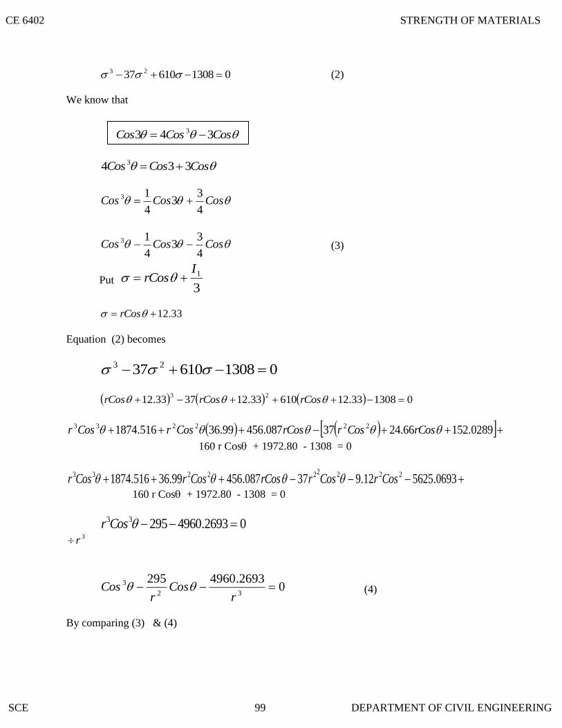
0130861037 23 (2)
We know that
CosCosCos 334 3
CosCosCos4
33
4
13
CosCosCos4
33
4
13 (3)
Put 3
1IrCos
33.12 rCos
Equation (2) becomes
0130861037 23
0130833.1261033.123733.1223
rCosrCosrCos
0289.15266.2437087.45699.36516.1874 222233 rCosCosrrCosCosrCosr
160 r Cos + 1972.80 - 1308 = 0
0693.562512.937087.45699.36516.1874 222222233 CosrCosrrCosCosrCosr
160 r Cos + 1972.80 - 1308 = 0
02693.496029533 Cosr 3r
02693.496029532
3 r
Cosr
Cos (4)
By comparing (3) & (4)
CosCosCos 343 3
CE 6402 STRENGTH OF MATERIALS
SCE 99 DEPARTMENT OF CIVIL ENGINEERING

2
295
4
1
r
r2 = 1180
r = 34.35
and
3
2693.4960
4
3
r
Cos
331.40534
2693.4960
4
3
Cos
3 = 60.6930
1 = 20.231o
2 = 1 + 120
2 = 140 .23 o
3 = 26.231 o
33.1211 rCos
= 34.35 Cos (140.23o) + 12.33
MPa530.441
33.1222 rCos
= 34.35 Cos (140.231o) + 12.33
MPa217.142
33.1233 rCos
= 34.35 Cos (260.231o) + 12.33
5016.63
Result:
1 = 20.231o
3 = 260.231o
2 = - 14.217 MPa
2 = 140.23o
1 = 44.530 MPa
3 = 6.5016 MPa
CE 6402 STRENGTH OF MATERIALS
SCE 100 DEPARTMENT OF CIVIL ENGINEERING

4.9 EXPLAIN THE ENERGY OF DISTORTION ( SHEAR STRAIN ENERGY ) AND
DILATATION
The strain energy can be split up on the following two strain energies.
i. Strain energy of distortion (shear strain energy)
ii. Strain energy of Dilatation (Strain energy of uniform compression (or)) tension
(or) volumetric strain energy )
Let e1 e2 an d e3 be the principal strain in the directions of principal stresses 1, 2 and
3.
Then
3211
1
Ee
1322
1
Ee
2133
1
Ee
Adding the above equation we get,
321321321 21
E
eee
21321
E
But e1 + e2 + e3 = e v (Volumetric strain)
321
21
Eev
If 0,0321 ve . This means that if sum of the three principal stress is
zero there is no volumetric change, but only the distortion occurs.
From the above discussion,
1. When the sum of three principal stresses is zero, there is no volumetric change
but only the distortion occurs.
CE 6402 STRENGTH OF MATERIALS
SCE 101 DEPARTMENT OF CIVIL ENGINEERING

4.13 MAXIMUM SHEAR STRESS THEORY
4.12 MAXIMUM PRINCIPAL STRESS THEORY
4.11 LIMITATIONS OF MAXIMUM PRINCIPAL STRESS THEORY
4.10 STATE THE PRINCIPAL THEORIES OF FAILURE
2. When the three principal stresses are equal to one another there is no distortion
but only volumetric change occurs.
Note:
In the above six theories,
et , ec = Tensile stress at the elastic limit in simple tension and
compression;
1, 2, 3 = Principal stresses in any complex system
(such that e1 > e2 > e3 )
It may be assumed that the loading is gradual (or) static (and there is no cyclic (or)
impact load.)
1. Maximum principal stress theory
2. Maximum shear stress (or) stress difference theory
3. Strain energy theory
4. Shear strain energy theory
5. Maximum principal strain theory
6. Mohr‟s Theory
1. On a mild steel specimen when spiel tension test is carried out sliding occurs
approximately 45o to the axis of the specimen; this shows that the failure in this case is
due to maximum shear stress rather than the direct tensile stress.
2. It has been found that a material which is even though weak in simple compression yet
can sustain hydrostatic pressure for in excess of the elastic limit in simple compression.
According to this theory failure will occur when the maximum principle tensile stress
(1) in the complex system reaches the value of the maximum stress at the elastic limit (et) in
the simple tension.
This theory implies that failure will occur when the maximum shear stress maximum
in the complex system reaches the value of the maximum shear stress in simple tension at elastic
limit (i.e)
CE 6402 STRENGTH OF MATERIALS
SCE 102 DEPARTMENT OF CIVIL ENGINEERING

4.19 STRESS TENSOR IN CARTESIAN COMPONENTS
4.18 LIMITATIONS IN MAXIMUM PRINCIPAL STRAIN THEORY
4.17 MAXIMUM PRINCIPAL
4.16 LIMITATIONS OF DISTORTION
4.15 SHEAR STRAIN ENERGY THEORY
4.14 LIMITATIONS OF MAXIMUM SHEAR STRESS THEORY
22
31
max
etl
(or) et 31
i. The theory does not give accurate results for the state of stress of pure shear in which
the maximum amount of shear is developed (i.e) Torsion test.
ii. The theory does not give us close results as found by experiments on ductile
materials. However, it gives safe results.
This theory is also called “ Distortion energy Theory” or “Von Mises - Henky Theory.”
According to this theory the elastic failure occurs where the shear strain energy per unit
volume in the stressed material reaches a value equal to the shear strain energy per unit volume
at the elastic limit point in the simple tension test.
ENERGY THEORY
1. The theory does to agree the experiment results for the material for which at is
quite different etc.
2. This theory is regarded as one to which conform most of the ductile material under
the action of various types of loading.
STRAIN THEORY
The theory states that the failure of a material occurs when the principal tensile strain in
the material reaches the strain at the elastic limit in simple tension (or) when the min minimum
principal strain (ie ) maximum principal compressive strain reaches the elastic limit in simple
compression.
i. The theory overestimates the behaviour of ductile materials.
ii. The theory does no fit well with the experimental results except for brittle
materials for biaxial tension.
xz
xy
x
ij
.'
yz
y
xy
z
yz
xz
CE 6402 STRENGTH OF MATERIALS
SCE 103 DEPARTMENT OF CIVIL ENGINEERING
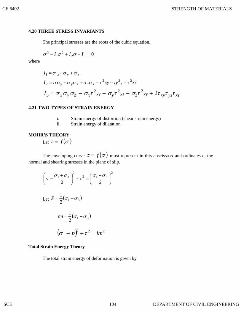
MOHR’S THEORY
4.21 TWO TYPES OF STRAIN ENERGY
4.20 THREE STRESS INVARIANTS
The principal stresses are the roots of the cubic equation,
032
2
1
3 III
where
zyxI 1
xzyxyI zzxzyy222
2
xzyzxyxyzxzyxyxZyxI 22223
i. Strain energy of distortion (shear strain energy)
ii. Strain energy of dilatation.
Let f
The enveloping curve f must represent in this abscissa and ordinates e, the
normal and shearing stresses in the plane of slip.
2
312
2
31
22
Let 312
1 P
312
1 m
222lmp
Total Strain Energy Theory
The total strain energy of deformation is given by
CE 6402 STRENGTH OF MATERIALS
SCE 104 DEPARTMENT OF CIVIL ENGINEERING

4.23 THE MAXIMUM PRINCIPAL STRESS THEORY IS CONTRADICTED IN THE
EXPLAIN THE MAXIMUM PRINCIPAL STRESS THEORY: ( RANKINE’S THEORY)
133221
2
3
2
2
2
1 22
1 v
EU
and strain energy in simple tension is
E
U2
20
This is the simplest and the oldest theory of failure
According to this theory failure will occur when the maximum principle tensile
stress (1) in the complex system reaches the value of the maximum stress at the
elastic limit (et) in the simple tension (or) the minimum principal stress (that is, the
maximum principal compressive stress), reaches the elastic limit stress () in
simple compression.
(ie.) 1 = et (in simple tension)
ac 3 (In simple compression)
3 Means numerical value of 3
If the maximum principal stress is the design criterion, the maximum principal stress
must not exceed the working for the material. Hence,
1
This theory disregards the effect of other principal stresses and of the shearing stresses
on other plane through the element. For brittle materials which do not fail by yielding
but fail by brittle fracture, the maximum principal stress theory is considered to be
reasonably satisfactory.
This theory appears to be approximately correct for ordinary cast – irons and brittle
metals.
FOLLOWING CASES:
1. On a mild steel specimen when simple tension test is carried out sliding occurs
approximately 45o to the axis of the specimen; this shows that the failure in the
case is due to maximum shear stress rather than the direct tensile stress.
CE 6402 STRENGTH OF MATERIALS
SCE 105 DEPARTMENT OF CIVIL ENGINEERING

4.25 EXPLAIN THE SHEAR STRAIN ENERGY THEORY
4.24 EXPLAIN THE
2. It has been found that a material which is even though weak in simple
compression yet can sustain hydrostatic pressure for in excess of the elastic limit
in simple compression.
MAXIMUM SHEAR STRESS (OR) STRESS DIFFERENCE THEORY
This theory is also called Guesti‟s (or) Tresca‟s theory.
This theory implies that failure will occur when the maximum shear stress
maximum in the complex system reaches the value of the maximum shear
stress in simple tension at the elastic limit i.e.
22
31
max
et
in simple tension.
(or) et 31
In actual design et in the above equation is replaced by the safe stress.
This theory gives good correlation with results of experiments on ductile materials.
In the case of two dimensional tensile stress and then the maximum stress
difference calculated to equate it to et.
Limitations of this theory:
i. The theory does not give accurate results for the state of stress of pure shear in
which the maximum amount of shear is developed (ie) Torsion test.
ii. The theory is not applicable in the case where the state of stress consists of
triaxial tensile stresses of nearly equal magnitude reducing, the shearing stress to
a small magnitude, so that failure would be by brittle facture rather than by
yielding.
iii. The theory does not give as close results as found by experiments on ductile
materials. However, it gives safe results.
This theory is also called “Distortion Energy Theory”: (or) “Von Mises – Henky
Theory”
According to this theory the elastic failure occurs where the shear strain energy per
unit volume in the stressed material reaches a value equal to the shear strain
energy per unit volume at the elastic limit point in the simple tension test.
Shear strain energy due to the principal stresses 1, 2, and 3 per unit volume of the
stress material.
CE 6402 STRENGTH OF MATERIALS
SCE 106 DEPARTMENT OF CIVIL ENGINEERING

4.26 EXPLAIN THE MAXIMUM PRINCIPAL STRAIN THEORY
2
13
2
32
2
2112
1
CU S
But for the simple tension test at the elastic limit point where there is only one principal
stress (ie) et we have the shear strain energy per unit volume which is given by
2221 0000
12
1tates
CU
Equating the two energies, we get
0
0
3
2
1
et
22
13
2
32
2
21 2 et
The above theory has been found to give best results for ductile material for which ecet
approximately.
Limitations of Distortion energy theory:
1. Te theory does to agree with the experimental results for the material for which et is
quite different from ec.
2. The theory gives 0et for hydrostatic pressure (or) tension, which means that the
material will never fail under any hydrostatic pressure (or) tension. When three equal
tensions are applied in three principal directions, brittle facture occurs and as such
maximum principal stress will give reliable results in this case.
3. This theory is regarded as one to which conform most of the ductile material under
the action of various types of loading.
This theory associated with St Venent
The theory states that the failure of a material occurs when the principal tensile
strain in the material reaches the strain at the elastic limit in simple tension (or)
when the minimum principal strain (ie) maximum principal compressive strain
reaches the elastic limit in simple compression.
Principal strain in the direction of principal stress 1,
CE 6402 STRENGTH OF MATERIALS
SCE 107 DEPARTMENT OF CIVIL ENGINEERING

3211
11
mEe
Principal strain in the direction of the principal stress 3,
2133
11
mEe
The conditions to cause failure according to eh maximum principal strain theory are:
E
e et1 (e1 must be +Ve)
and
E
e ec3 (e3 must be -Ve)
EmE
et
321
11
EmE
et
213
11
etm
311
1
ecm
313
1
To prevent failure:
etm
321
1
cem
213
1
At the point of elastic failure:
etm
321
1
and cem
213
1
For design purposes,
tm
213
1
cm
213
1
(where, t and c are the safe stresses)
Limitations:
CE 6402 STRENGTH OF MATERIALS
SCE 108 DEPARTMENT OF CIVIL ENGINEERING

EXPLAIN MOHR’S THEORY
4.27 EXPLAIN THE STRAIN ENERGY THEORY
i. The theory overestimates the behavior of ductile materials.
ii. Te theory does not fit well with the experimental results except for brittle materials for
biaxial tension.
The total stain energy of deformation is given by
133221
2
3
2
2
2
1 22
1 v
EU
and the strain energy under simple tension is
E
U e
2
2
Hence for the material to yield,
133221
2
3
2
2
2
1 2 v
The total elastic energy stored in a material before it reaches the plastic state can have no
significance as a limiting condition, since under high hydrostatic pressure, large amount of strain
energy ma be stored without causing either fracture (or) permanent deformation.
A material may fail either through plastic slip (or) by fracture when either the shearing
stress in the planes of slip has increased.
Let f
The enveloping curve f must represent in their abscissa and ordinates , the
normal and shearing stresses in the plane of slip. Now
2
312
2
31
22
Let 312
1 P
312
1 m
then
222mp
This equation represents the family of major principal stress circles in parameter form.
The equation of this envelope is obtained by partially differentiating with respect to P
CE 6402 STRENGTH OF MATERIALS
SCE 109 DEPARTMENT OF CIVIL ENGINEERING

222mP
2222 2 mPp
dp
dp m
m
.
dp
d mm
2
1.
This is to equation of Mohr‟s envelope of the major
principal stress in parameter form.
IN A STEEL MEMBER, AT A POINT THE MAJOR PRINCIPAL STRESS IS 180
MN/M2 AND THE MINOR PRINCIPAL STRESSES IS COMPRESSIVE. IF THE
TENSILE YIELD POINT OF THE STEEL IS 225 MN/M2, FIND THE VALUE OF
THE MINOR PRINCIPAL STRESS AT WHICH YIELDING WILL
COMMENCE, ACCORDING TO EACH OF THE FOLLOWING CRITERIA OF
FAILURE.
i. Maximum shearing stress
ii. Maximum total strain energy
iii. Maximum shear strain energy
Take Poisson’s ratio = 0.26
Solution:
Major principal stress, 2
1 /180 mMN
Yield point stress 2
2 /225 mMN
26.01
m
To calculate minor principal stress (2)
(i) Maximum shearing stress criterion
e 12
= 180 - 225
2 = - 45 MN/m2
2 = 45 MN/m
2 (comp)
ii. Maximum total strain energy criterion:
e 21
CE 6402 STRENGTH OF MATERIALS
SCE 110 DEPARTMENT OF CIVIL ENGINEERING
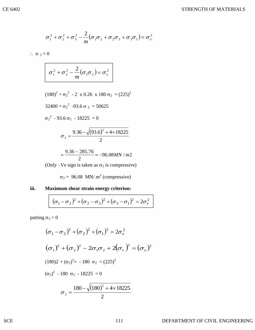
2
133221
2
3
2
2
2
1
2e
m
3 = 0
(180)2 + 2
2 - 2 x 0.26 x 180 2 = (225)
2
32400 + 2
2 -93.6 2 = 50625
22 - 93.6 2 - 18225 = 0
2
1822546.9336.92
2
2/08.962
76.28536.9mMN
(Only –Ve sign is taken as 2 is compressive)
2 = 96.08 MN/ m2 (compressive)
iii. Maximum shear strain energy criterion:
putting 3 = 0
221
22
221 2 e
22
121
2
2
2
1 22 e
(180)2 + (2)2+ - 180 2 = (225)
2
(2)2 - 180 2 - 18225 = 0
2
1822541801802
2
2
21
2
2
2
1
2e
m
2213
232
221 2 e
CE 6402 STRENGTH OF MATERIALS
SCE 111 DEPARTMENT OF CIVIL ENGINEERING

2
2 /25.722
5.324180mMN
2 = 72.25 MN/m2 (Compressive)
IN A MATERIAL THE PRINCIPAL STRESSES ARE 60 MN/M2, 48 MN/M
2 AND - 36
MN/M2. CALCULATE
i. TOTAL STRAIN ENERGY
ii. VOLUMETRIC STRAIN ENERGY
iii. SHEAR STRAIN ENERGY
iv. FACTOR OF SAFETY ON THE TOTAL STRAIN ENERGY
CRITERIA IF THE MATERIAL YIELDS AT 120 MN/M2.
TAKE E = 200 GN/M2+ AND 1/M = 0.3
Solution: Given Data:
Principal stresses:
1 = + 60 MN/m2
2 = + 48 MN/m
2
3 = - 36 MN/m
2
Yield stress, e = 120 MN /m2
E = 200 GN/m2, 1/m = 0.3
i. Total strain energy per unit volume:
133221
2
3
2
2
2
1
2
2
1
mEU
60364848603.02364860102002
10 222
9
12
U
2160172828806.01296230436005.2U
U = 19.51 KNm/m3
ii. Volumetric strain energy per unit volume:
CE 6402 STRENGTH OF MATERIALS
SCE 112 DEPARTMENT OF CIVIL ENGINEERING

3
9
12210
102002
3.02110364860
3
1
ve
e v = 1.728 KN/m3
iii. shear strain energy per unit volume
Where,
2/923.763.012
200
112
mGN
m
EC
222
9
12
60363648486010923.7612
101
se
31092167056144083.1 se
3/78.17 mKNmes
iv. Factor of safety (F.O.S)
Strain energy per unit volume under uniaxial loading is
33
9
262
/3610102002
10120
2mKNm
E
e
F.O.S 845.151.19
36
IN A MATERIAL THE PRINCIPAL STRESSES ARE 50 N/MM2, 40 N/MM
2 AND - 30
N/MM2, CALCULATE:
i. TOTAL STRAIN ENERGY
ii. VOLUMETRIC STRAIN ENERGY
E
mev
2
/21
3
1 2
321
213
232
221
12
1
ces
CE 6402 STRENGTH OF MATERIALS
SCE 113 DEPARTMENT OF CIVIL ENGINEERING

iii. SHEAR STRAIN ENERGY AND
iv. FACTOR OF SAFETY ON THE TOTAL STRAIN ENERGY
CRITERION IF THE MATERIAL YIELD AT 100 N/MM2.
TAKE E = 200 X 103 N/MM
2 AND POISSION RATIO = 0 .28
Solution:
Given,
Principal stresses:
2
1 /50 mmN
2
2 /40 mmN
2
3 /30 mmN
Yield stress, 2/100 mmNe
i. Total strain energy per unit volume:
133221
2
3
2
2
2
1
2
2
1
mEU
5030304040503.02304050102002
1 222
3
1500120020006.09001600250010400
13
7006.0500010400
13
542010400
13
U = 13.55 KNm/m3
ii)Volumetric strain energy per unit volume:
E
mev
2
/21
3
1 2221
CE 6402 STRENGTH OF MATERIALS
SCE 114 DEPARTMENT OF CIVIL ENGINEERING

3
2
102002
3.021304050
3
1
ve
3
2
10400
4.060
3
1
310
001.03600
3
1ve
ev = 1.2 K N m / m3
iii. Shear strain energy
2
13
2
32
2
2112
1
Ces
where
233
/10923.763.012
10200
/112mmN
m
EC
222
3503030404050
10923.7612
1
se
6400490010010076.923
13
se
3/35.12 mKNnes
iv. Factor of safety (F.O.S)
Strain energy per unit volume under uniaxial loading is
3
3
22
/254102002
100
2mKNm
E
e
845.155.13
25.. SOF
CE 6402 STRENGTH OF MATERIALS
SCE 115 DEPARTMENT OF CIVIL ENGINEERING

IN A MATERIAL THE PRINCIPAL STRESSES ARE 50 N/MM2, 40 N/MM
2 AND - 30
N/MM2, CALCULATE:
v. TOTAL STRAIN ENERGY
vi. VOLUMETRIC STRAIN ENERGY
vii. SHEAR STRAIN ENERGY AND
viii. FACTOR OF SAFETY ON THE TOTAL STRAIN ENERGY
CRITERION IF THE MATERIAL YIELD AT 100 N/MM2.
TAKE E = 200 X 103 N/MM
2 AND POISSION RATIO = 0 .28
Solution:
Given,
Principal stresses:
2
1 /50 mmN
2
2 /40 mmN
2
3 /30 mmN
Yield stress, 2/100 mmNe
i. Total strain energy per unit volume:
133221
2
3
2
2
2
1
2
2
1
mEU
5030304040503.02304050102002
1 222
3
1500120020006.09001600250010400
13
7006.0500010400
13
542010400
13
U = 13.55 KNm/m3
CE 6402 STRENGTH OF MATERIALS
SCE 116 DEPARTMENT OF CIVIL ENGINEERING

ii)Volumetric strain energy per unit volume:
E
mev
2
/21
3
1 2221
3
2
102002
3.021304050
3
1
ve
3
2
10400
4.060
3
1
310
001.03600
3
1ve
ev = 1.2 K N m / m3
iii. Shear strain energy
2
13
2
32
2
2112
1
Ces
where
233
/10923.763.012
10200
/112mmN
m
EC
222
3503030404050
10923.7612
1
se
6400490010010076.923
13
se
3/35.12 mKNnes
iv. Factor of safety (F.O.S)
Strain energy per unit volume under uniaxial loading is
3
3
22
/254102002
100
2mKNm
E
e
CE 6402 STRENGTH OF MATERIALS
SCE 117 DEPARTMENT OF CIVIL ENGINEERING

4.30 THEORIES OF FAILURE
4.29 SHEAR STRAIN ENERGY PER UNIT VOLUME
845.155.13
25.. SOF
2
132
322
2112
1
Cs
where
m
EC
112
The principal theories are:
1. Maximum principal stress theory
2. Maximum shear stress (or) stress difference theory
3. Strain energy theory
4. Shear strain energy theory
5. Maximum principal strain theory
CE 6402 STRENGTH OF MATERIALS
SCE 118 DEPARTMENT OF CIVIL ENGINEERING
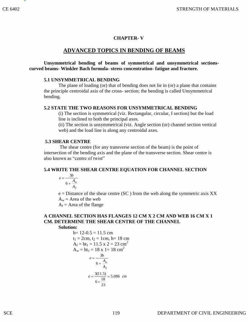
A CHANNEL SECTION HAS FLANGES 12 CM X 2 CM AND WEB 16 CM X 1
5.4 WRITE THE SHEAR CENTRE EQUATION FOR CHANNEL SECTION
5.3 SHEAR CENTRE
5.2 STATE THE TWO REASONS FOR UNSYMMETRICAL BENDING
5.1 UNSYMMETRICAL BENDING
CHAPTER- V
ADVANCED TOPICS IN BENDING OF BEAMS
Unsymmetrical bending of beams of symmetrical and unsymmetrical sections-
curved beams- Winkler Bach formula- stress concentration- fatigue and fracture.
The plane of loading (or) that of bending does not lie in (or) a plane that contains
the principle centroidal axis of the cross- section; the bending is called Unsymmetrical
bending.
(i) The section is symmetrical (viz. Rectangular, circular, I section) but the load
line is inclined to both the principal axes.
(ii) The section is unsymmetrical (viz. Angle section (or) channel section vertical
web) and the load line is along any centroidal axes.
The shear centre (for any transverse section of the beam) is the point of
intersection of the bending axis and the plane of the transverse section. Shear centre is
also known as “centre of twist”
f
w
A
A
be
6
3
e = Distance of the shear centre (SC ) from the web along the symmetric axis XX
Aw = Area of the web
Af = Area of the flange
CM. DETERMINE THE SHEAR CENTRE OF THE CHANNEL
Solution:
b= 12-0.5 = 11.5 cm
t1 = 2cm, t2 = 1cm, h= 18 cm
Af = bt1 = 11.5 x 2 = 23 cm2
Aw = ht2 = 18 x 1= 18 cm2
f
w
A
A
be
6
3
cme 086.5
23
186
)5.11(3
CE 6402 STRENGTH OF MATERIALS
SCE 119 DEPARTMENT OF CIVIL ENGINEERING

5.6 DERIVE THE EQUATION OF SHEAR CENTRE FOR CHANNEL SECTION
5.5 WRITE THE SHEAR CENTRE EQUATION FOR UNSYMMETRICAL I SECTION
xxI
bbhte
4
)( 212
21
e = Distance of the shear centre (SC) from the web along the symmetric axis XX
t1 = thickness of the flange
h = height of the web
b1 = width of the flange in right portion.
b2 = width of the flange in left portion.
Ixx = M.O.I of the section about XX axis.
A channel section (flanges: b x t1 ; Web h x t2) with XX as the horizontal symmetric
axis.
Let S = Applied shear force. (Vertical downward X)
(Then S is the shear force in the web in the upward direction)
S1 = Shear force in the top flange (there will be equal and opposite shear force
in the bottom flange as shown.)
Now, shear stress () in the flange at a distance of x from the right hand edge (of the top
flange)
tI
ySA
xa
2
.1
hxtyA (where t = t1 , thickness of flange)
xx
xh
xx I
Sh
tI
xSt
22.
.
.
1
1
Shear force is elementary area
dztddxtd AA 11 ..
Total shear force in top flange
dxt
b
..
0
1 (where b = breadth of the flange)
b
xx
b
xx
xdxI
shtdxt
I
hSS
0
11
0
12
.;2
(or) 4
.2
11
b
I
ShtS
xx
Let e = Distance of the shear centre (sc) from taking moments of shear forces about the
centre O of the web,We get
CE 6402 STRENGTH OF MATERIALS
SCE 120 DEPARTMENT OF CIVIL ENGINEERING

5.7 DERIVE THE EQUATION OF
hSeS .. 1
xxxx I
bhtSh
b
I
Sht
4
..
4.
221
21
xxI
thbe
4
122
(1)
Now, 122
.12
23
2
2
1
31 hth
tbtb
Ixx
122
.
6
32
21
31 hthtbbt
122
32
21 hthbt
(neglecting the term 3
3
1bt, being negligible in comparison to other
terms)(or) 12
2
12bbtht
hI xx
Substitute the value of Ixx in equation (1) we get,
12
12
122
122
6
3
6
12
4 htht
tb
bthth
thbe
Let bt1 = Af (area of the flange)
ht2 = A (area of the web)
Then
f
wfw
f
A
A
b
AA
bAe
6
3
6
3
i.e
SHEAR CENTER FOR UNEQUAL I-SECTION
Solution:
An unequal I – section which is symmetrical about XX axis.
f
w
A
A
be
6
3
CE 6402 STRENGTH OF MATERIALS
SCE 121 DEPARTMENT OF CIVIL ENGINEERING

5.8 DERIVE THE STRESSES IN CURVED BARS US
Shear stress in any layer,
It
ySA
where I = IXX =
12122
3
121
31
21
hxtbb
tbb
Shear force S1 :
2
... 11
hxtyAdxtdA
S1 =
1
0
11
1
2
..b
XX
dxxth
tI
txSdA
= 1
0
12
..b
XX
dxth
I
xS =
XX
b
XX I
bShtx
I
Sht
422
211
0
21
1
Similarly the shear force (S2) in the other part of the flange,
S2 =XXI
bSht
4
221
Taking moments of the shear forces about the centre of the web O, we get
S2. h = S1. h + S .e (S3 = S for equilibrium)
(where, e = distance of shear centre from the centre of the web)
or, (S2 – S1) h = S.e
eSI
bbtSh
XX
.4
)( 21
221
2
ING WINKLER – BACH THEORY
The simple bending formula, however, is not applicable for deeply curved beams where
the neutral and centroidal axes do not coincide. To deal with such cases Winkler – Bach Theory
is used.
A bar ABCD initially; in its unstrained state. Let AB‟CD‟ be the strained position of the
bar.
xxI
bbhte
4
21
22
21
CE 6402 STRENGTH OF MATERIALS
SCE 122 DEPARTMENT OF CIVIL ENGINEERING
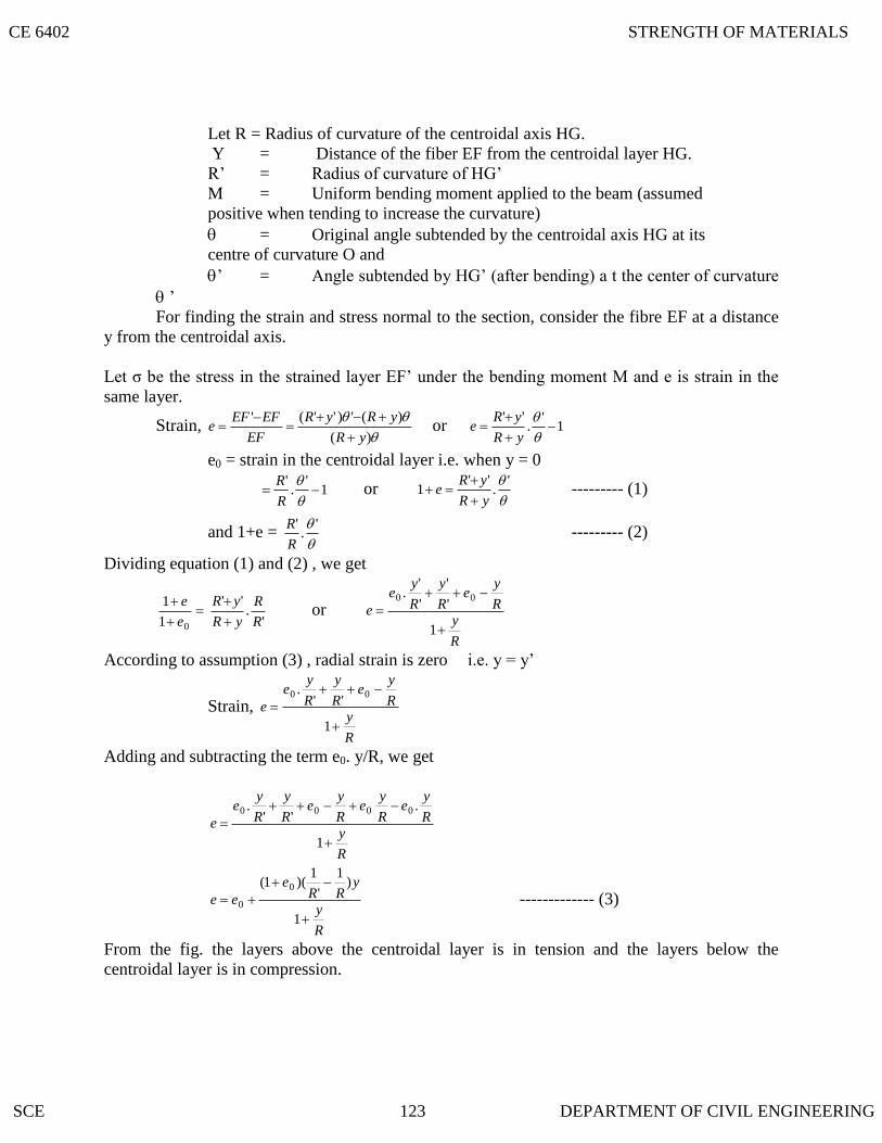
Let R = Radius of curvature of the centroidal axis HG.
Y = Distance of the fiber EF from the centroidal layer HG.
R‟ = Radius of curvature of HG‟
M = Uniform bending moment applied to the beam (assumed
positive when tending to increase the curvature)
= Original angle subtended by the centroidal axis HG at its
centre of curvature O and
‟ = Angle subtended by HG‟ (after bending) a t the center of curvature
‟
For finding the strain and stress normal to the section, consider the fibre EF at a distance
y from the centroidal axis.
Let σ be the stress in the strained layer EF‟ under the bending moment M and e is strain in the
same layer.
Strain,
)(
)(')''('
yR
yRyR
EF
EFEFe
or 1
'.
''
yR
yRe
e0 = strain in the centroidal layer i.e. when y = 0
1'
.'
R
R or
'.
''1
yR
yRe
--------- (1)
and 1+e =
'.
'
R
R --------- (2)
Dividing equation (1) and (2) , we get
01
1
e
e
'.
''
R
R
yR
yR
or
R
y
R
ye
R
y
R
ye
e
1
'
'
'
'. 00
According to assumption (3) , radial strain is zero i.e. y = y‟
Strain,
R
y
R
ye
R
y
R
ye
e
1
''. 00
Adding and subtracting the term e0. y/R, we get
R
y
R
ye
R
ye
R
ye
R
y
R
ye
e
1
.''
. 0000
R
y
yRR
e
ee
1
)1
'
1)(1( 0
0 ------------- (3)
From the fig. the layers above the centroidal layer is in tension and the layers below the
centroidal layer is in compression.
CE 6402 STRENGTH OF MATERIALS
SCE 123 DEPARTMENT OF CIVIL ENGINEERING

Stress , σ = Ee = )
1
)1
'
1)(1(
(0
0
R
y
yRR
e
eE
___________ (4)
Total force on the section, F = dA.
Considering a small strip of elementary area dA, at a distance of y from the centroidal layer HG,
we have
dA
R
y
yRR
e
EdAeEF
1
)1
'
1)(1(
.0
0
dA
R
y
y
RReEdAeEF
1
)1
,
1(1. 00
dA
R
y
y
RReEAeEF
1
)1
,
1(1. 00 ____________ (5)
where A = cross section of the bar
The total resisting moment is given given by
dA
R
y
yRR
e
EydAeEdAyM
1
)1
'
1)(1(
...
20
0
dA
R
y
y
RReEeEM
1
)1
,
1(10.
2
00 (since )0ydA
M = E (1+e0)
dA
R
y
y
RR1
1
'
12
Let
22
1
AhdA
R
y
y
Where h2
= a constant for the cross section of the bar
M = E (1+e0)21
'
1Ah
RR
----------- (6)
Now,
dAyR
yydA
yR
RydA
R
y
y 2
..
1
= dA
yR
yydA .
2
dA
R
y
y
1
dA
R
y
y
R.
1
10
2
= 21Ah
R ---------- (7)
Hence equation (5) becomes
F = Ee0 .A – E (1+e0 )R
Ah
RR
21
'
1
Since transverse plane sections remain plane during bending
F = 0
0 = Ee0 .A – E (1+e0 )R
Ah
RR
21
'
1
CE 6402 STRENGTH OF MATERIALS
SCE 124 DEPARTMENT OF CIVIL ENGINEERING

E e0 .A = E (1+e0 )R
Ah
RR
21
'
1
e0 = (1+e0 )R
Ah
RR
21
'
1
(or)
2
0
h
Re(1+e0 )
RR
1
'
1
Substituting the value of 2
0
h
Re(1+e0 )
RR
1
'
1 in the equation (6)
M = E 2
2
0 Ahh
Re = e0 EAR
Or EAR
Me 0 substituting the value of e0 in equation (4)
2
0*
1
*h
Re
R
y
yE
AR
M
(or) EAR
M
h
R
R
y
yE
AR
M**
1
*2
2
1*
1
*h
R
y
Ry
AR
M
AR
M
yR
y
h
R
AR
M2
2
1 (Tensile)
yR
y
h
R
AR
M2
2
1 (Compressive)
The curved member shown in fig. has a solid circular cross –section 0.01 m in diameter.
If the maximum tensile and compressive stresses in the member are not to exceed 150
MPa and 200 MPa. Determine the value of load P that can safely be carried by the
member.
Solution:
Given,
d = 0.10 m; R = 0.10 m; G = 150 MPa = 150 MN / m2 (tensile )
2 = 200 MPa = 200 MN / m2 (Compressive)
Load P:
Refer to the fig . Area of cross section,
2322
10854.710.044
md
A
Bending moment, m = P (0.15 + 0.10) =0.25 P
CE 6402 STRENGTH OF MATERIALS
SCE 125 DEPARTMENT OF CIVIL ENGINEERING

2
422
10.0
10.0.
128
1
16
dh = 7.031 x 10
-4 m
2
Direct stress, compA
pd
Bending stress at point 1 due to M:
yR
y
h
R
AR
Mb 2
2
1 1 (tensile)
Total stress at point 1,
11 bd
yR
y
h
R
AR
M
A
P2
2
1150 (tensile)
05.010.0
05.0
10031.7
10.01
10.010854.7
25.0
10854.7150
4
2
33
PP
= -127.32 P + 318.31 P x 5. 74
= 1699.78 P
KNP 25.8878.1699
10150 3
(i)
Bending stress at point 2 due to M:
1
2
2
2yR
y
h
R
AR
Mb (comp)
Total stress at point 2,
22 bd
1200
2
2
yR
y
h
R
AR
M
A
P
1
05.010.0
05.0
10031.7
10.0
10.010854.7
25.0
10854.7 4
2
33
PP
=127.32 P + 318. 31 P x 13.22
= 4335.38 P
MNP38.4335
200
KNP 13.4638.4335
10200 3
(ii)
By comparing (i) & (ii) the safe load P will be lesser of two values
CE 6402 STRENGTH OF MATERIALS
SCE 126 DEPARTMENT OF CIVIL ENGINEERING
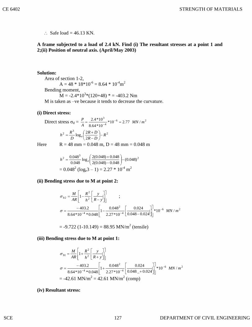
Safe load = 46.13 KN.
A frame subjected to a load of 2.4 kN. Find (i) The resultant stresses at a point 1 and
2;(ii) Position of neutral axis. (April/May 2003)
Solution:
Area of section 1-2,
A = 48 * 18*10-6
= 8.64 * 10-4
m2
Bending moment,
M = -2.4*103*(120+48) * = -403.2 Nm
M is taken as –ve because it tends to decrease the curvature.
(i) Direct stress:
Direct stress σd = 26
4
3
/77.210*10*64.8
10*4.2mMN
A
P
23
2
2
2log R
DR
DR
D
Rh e
Here R = 48 mm = 0.048 m, D = 48 mm = 0.048 m
23
2 )048.0(048.0)048.0(2
048.0)048.0(2log
048.0
048.0
eh
= 0.0482 (loge3 – 1) = 2.27 * 10
-4 m
2
(ii) Bending stress due to M at point 2:
yR
y
h
R
AR
Mb 2
2
2 1 ;
26
4
2
4/10*
024.0048.0
024.0
10*27.2
048.01
048.0*10*64.8
2.403mMN
= -9.722 (1-10.149) = 88.95 MN/m2 (tensile)
(iii) Bending stress due to M at point 1:
yR
y
h
R
AR
Mb 2
2
1 1
26
4
2
4/10*
024.0_048.0
024.0
10*27.2
048.01
048.0*10*64.8
2.403mMN
= -42.61 MN/m2 = 42.61 MN/m
2 (comp)
(iv) Resultant stress:
CE 6402 STRENGTH OF MATERIALS
SCE 127 DEPARTMENT OF CIVIL ENGINEERING

Resultant stress at point 2,
σ2 = σd + σb2 = 2.77 + 88.95 = 91.72 MN/m2 (tensile)
Resultant stress at point 1,
σ1 = σd + σb1 = 2.77 -42.61 = 39.84 MN/m2 (comp)
(v) Position of the neutral axis:
42
4
22
2
10*27.2048.0
10*27.2*048.0y
hR
Rhy
= -0.00435 m = - 4.35 mm
Hence, neutral axis is at a radius of 4.35 mm
A ring carrying a load of 30 kN. Calculate the stresses at 1 and 2.
Solution:
Area of cross-section = 2222 01131.01.113124
mcmcmx
Bending moment M = 30*103 * (13.5*10-2
)Nm = 4050 Nm
h2
= ......*128
1
16 2
42
R
dd
Here d = 12 cm, R = 7.5 +6 = 13.5 cm
h2
=2
42
5.13
12*
128
1
16
12 = 9.89 cm
2 = 9.89*10
-4 m
2
Direct Stress σd = 263
/65.210*01131.0
10*30mMN
A
P
Bending stress at point 1 due to M,
yR
y
h
R
AR
Mb 2
2
1 1
6
4
2
1 10*06.0135.0
06.0
10*89.9
135.01
135.0*01131.0
4050
b 2.65*6.6
7 = 17.675 MN/m2 (tensile)
Bending stress at point 2 due to M,
yR
y
h
R
AR
Mb 2
2
2 1
6
4
2
1 10*06.0135.0
06.0
10*89.9
135.01
135.0*01131.0
4050
b 2.65*13.
74 = 36.41 MN/m2 (comp)
CE 6402 STRENGTH OF MATERIALS
SCE 128 DEPARTMENT OF CIVIL ENGINEERING

Hence σ1 = σd + σb1 = -2.65 + 17.675
= 15.05 MN /m2 (tensile)
and σ2 = σd + σb2 = -2.65 – 36.41
= 39.06 MN/m2 (comp)
A curved bar is formed of a tube of 120 mm outside diameter and 7.5 mm thickness. The
centre line of this is a circular arc of radius 225 mm. The bending moment of 3 kNm
tending to increase curvature of the bar is applied. Calculate the maximum tensile and
compressive stresses set up in the bar.
Solution:
Outside diameter of the tube, d2 = 120 mm = 0.12 m
Thickness of the tube = 7.5 mm
Inside diameter of the tube, d1 = 120-2*7.5 = 105 mm = 0.105m
Area of cross-section,
222 00265.015.012.04
mA
Bending moment M = 3 kNm
Area of inner circle,
221 00866.0105.0
4mA
Area of outer circle,
222 01131.012.0
4mA
For circular section,
h2
= ......*128
1
16 2
42
R
dd
For inner circle,
h2
= ......*128
1
16 2
41
21
R
dd
h2
= 4
2
42
10*08.7225.0
105.0*
128
1
16
105.0
For outer circle,
h2
= ......*128
1
16 2
42
22
R
dd; h
2= 4
2
42
10*32.9225.0
12.0*
128
1
16
12.0
211
222
2 hAhAAh
0.00265 h2 = 0.01131*9.32*10
-4 – 0.00866*7.078*10
-4
h2 = 0.00166 m
2, and R
2/h
2 = 0.225
2/0.00166 = 30.49
Maximum stress at A,
yR
y
h
R
AR
MA 2
2
1 (where, y = 60 mm = 0.06 m)
CE 6402 STRENGTH OF MATERIALS
SCE 129 DEPARTMENT OF CIVIL ENGINEERING

263
/10*06.0225.0
06.049.301
225.0*00265.0
10*3mMNA
σA = 37.32 MN/m2 (tensile)
Maximum stress at B,
yR
y
h
R
AR
MB 2
2
1
263
/10*06.0225.0
06.049.301
225.0*00265.0
10*3mMNB
σB = 50.75 MN/m2
(comp)
A CURVED BEAM HAS A T-SECTION. THE INNER RADIUS IS 300 MM. WHAT IS
THE ECCENTRICITY OF THE SECTION?
Solution:
Area of T-section, = b1t1 + b2t2
= 60*20 + 80*20 = 2800 mm2
To find c.g of T- section, taking moments about the edge LL, we get
21
2211
AA
xAxAx
)20*80()20*60(
)10*20*80)(20*80()202
60)(20*60(
x =27.14 mm
Now R1 = 300 mm; R2 = 320 mm; R= 327.14 mm; R3 = 380 mm
Using the Relation:
2
2
31
1
22
32 log.log. R
R
Rt
R
Rb
A
Rh ee
23
2 )14.327()320
380(log*20)
300
320(log*80
2800
)14.327(
eeh
= 12503.8(5.16+3.44) – 107020.6 = 512.08
y = )(56.108.512)14.327(
08.512*14.327222
2
mm
hR
Rh
where y = e (eccentricity) = distance of the neutral axis from the centroidal axis.
Negative sign indicates that neutral axis is locates below the centroidal axis.
CE 6402 STRENGTH OF MATERIALS
SCE 130 DEPARTMENT OF CIVIL ENGINEERING
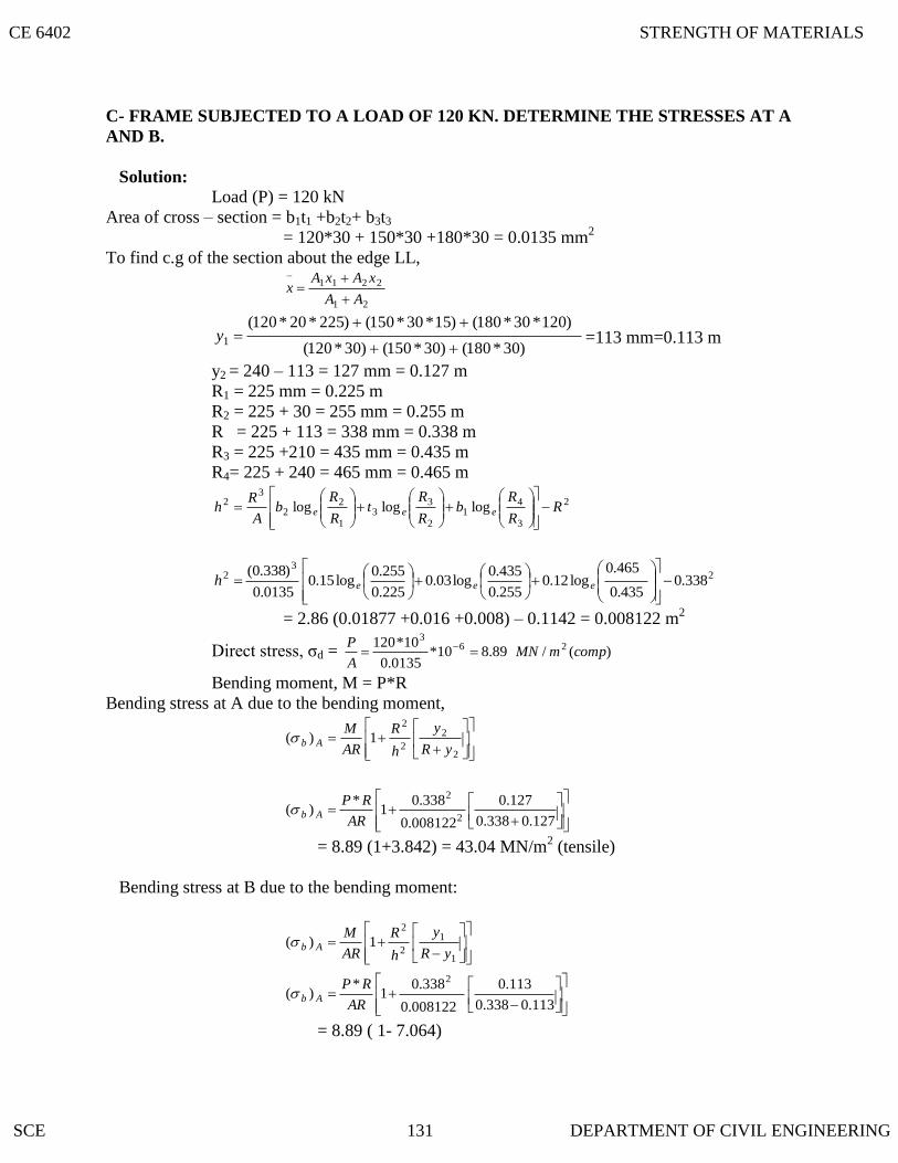
C- FRAME SUBJECTED TO A LOAD OF 120 KN. DETERMINE THE STRESSES AT A
AND B.
Solution:
Load (P) = 120 kN
Area of cross – section = b1t1 +b2t2+ b3t3
= 120*30 + 150*30 +180*30 = 0.0135 mm2
To find c.g of the section about the edge LL,
21
2211
AA
xAxAx
)30*180()30*150()30*120(
)120*30*180()15*30*150()225*20*120(1
y =113 mm=0.113 m
y2 = 240 – 113 = 127 mm = 0.127 m
R1 = 225 mm = 0.225 m
R2 = 225 + 30 = 255 mm = 0.255 m
R = 225 + 113 = 338 mm = 0.338 m
R3 = 225 +210 = 435 mm = 0.435 m
R4= 225 + 240 = 465 mm = 0.465 m
2
3
41
2
33
1
22
32 logloglog R
R
Rb
R
Rt
R
Rb
A
Rh eee
23
2 338.0435.0
465.0log12.0
255.0
435.0log03.0
225.0
255.0log15.0
0135.0
)338.0(
eeeh
= 2.86 (0.01877 +0.016 +0.008) – 0.1142 = 0.008122 m2
Direct stress, σd = )(/89.810*0135.0
10*120 263
compmMNA
P
Bending moment, M = P*R
Bending stress at A due to the bending moment,
2
2
2
2
1)(yR
y
h
R
AR
MAb
127.0338.0
127.0
008122.0
338.01
*)(
2
2
AR
RPAb
= 8.89 (1+3.842) = 43.04 MN/m2 (tensile)
Bending stress at B due to the bending moment:
1
1
2
2
1)(yR
y
h
R
AR
MAb
113.0338.0
113.0
008122.0
338.01
*)(
2
AR
RPAb
= 8.89 ( 1- 7.064)
CE 6402 STRENGTH OF MATERIALS
SCE 131 DEPARTMENT OF CIVIL ENGINEERING
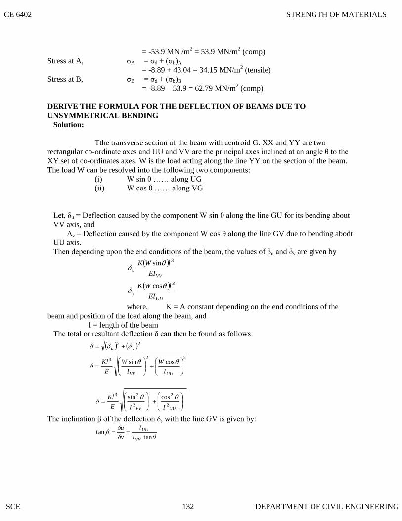
= -53.9 MN /m2 = 53.9 MN/m
2 (comp)
Stress at A, σA = σd + (σb)A
= -8.89 + 43.04 = 34.15 MN/m2 (tensile)
Stress at B, σB = σd + (σb)B
= -8.89 – 53.9 = 62.79 MN/m2 (comp)
DERIVE THE FORMULA FOR THE DEFLECTION OF BEAMS DUE TO
UNSYMMETRICAL BENDING
Solution:
Tthe transverse section of the beam with centroid G. XX and YY are two
rectangular co-ordinate axes and UU and VV are the principal axes inclined at an angle θ to the
XY set of co-ordinates axes. W is the load acting along the line YY on the section of the beam.
The load W can be resolved into the following two components:
(i) W sin θ …… along UG
(ii) W cos θ …… along VG
Let, δu = Deflection caused by the component W sin θ along the line GU for its bending about
VV axis, and
Δv = Deflection caused by the component W cos θ along the line GV due to bending abodt
UU axis.
Then depending upon the end conditions of the beam, the values of δu and δv are given by
VVu
EI
lWK 3sin
UUv
EI
lWK 3cos
where, K = A constant depending on the end conditions of the
beam and position of the load along the beam, and
l = length of the beam
The total or resultant deflection δ can then be found as follows:
22vu
223 cossin
UUVV I
W
I
W
E
Kl
UUVV IIE
Kl2
2
2
23 cossin
The inclination β of the deflection δ, with the line GV is given by:
tantan
VV
UU
I
I
v
u
CE 6402 STRENGTH OF MATERIALS
SCE 132 DEPARTMENT OF CIVIL ENGINEERING
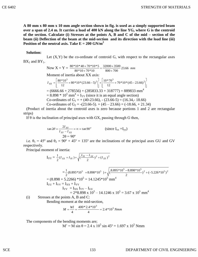
A 80 mm x 80 mm x 10 mm angle section shown in fig. is used as a simply supported beam
over a span of 2.4 m. It carries a load of 400 kN along the line YG, where G is the centroid
of the section. Calculate (i) Stresses at the points A, B and C of the mid – section of the
beam (ii) Deflection of the beam at the mid-section and its direction with the load line (iii)
Position of the neutral axis. Take E = 200 GN/m2
Solution: Let (X,Y) be the co-ordinate of centroid G, with respect to the rectangular axes
BX1 and BY1.
Now X = Y = mm66.23700800
350032000
10*7010*80
5*10*7040*10*80
Moment of inertia about XX axis:
2
32
3
)66.2345(*10*7012
70*10)566.23(*10*80
12
10*80XXI
= (6666.66 + 278556) + (285833.33 + 318777) = 889833 mm4
= 8.898 * 105 mm
4 = IYY (since it is an equal angle section)
Co-ordinates of G1 = + (40-23.66), - (23.66-5) = (16.34,- 18.66)
Co-ordinates of G2 = -(23.66-5). + (45 – 23.66) = (-18.66, + 21.34)
(Product of inertia about the centroid axes is zero because portions 1 and 2 are rectangular
strips)
If θ is the inclination of principal axes with GX, passing through G then,
90tan2
2tan
XXXY
XY
II
I (since Ixx =Iyy)
2θ = 90º
i.e. θ1 = 45º and θ2 = 90º + 45º = 135º are the inclinations of the principal axes GU and GV
respectively.
Principal moment of inertia:
IUU = 22 )()2
()(2
1XY
XXYYYYXX I
IIII
= 25255
55 )10*226.5()2
10*898.810*895.8()10*898.810*895.8(
2
1
= (8.898 + 5.2266) *105 = 14.1245*10
5 mm
4
IUU + IVV = IXX + IYY
IVV = IXX IYY – IUU
= 2*8.898 x 105 – 14.1246 x 10
5 = 3.67 x 10
5 mm
4
(i) Stresses at the points A, B and C:
Bending moment at the mid-section,
Nmm
WlM 5
3
10*4.24
10*4.2*400
4
The components of the bending moments are;
M‟ = M sin θ = 2.4 x 10⁵ sin 45º = 1.697 x 10
5 Nmm
CE 6402 STRENGTH OF MATERIALS
SCE 133 DEPARTMENT OF CIVIL ENGINEERING

M‟‟ = M cos θ = 2.4 x 10⁵ cos 45º = 1.697 x 10
5 Nmm
u,v co-ordinates:
Point A: x = -23.66, y = 80-23.66 = 56.34 mm
u = x cos θ + y sin θ
= -23.66 x cos 45º + 56.34 x sin 45º = 23.1 mm
v = y cosθ + x sin θ
= 56.34 cos 45º - (-23.66 x sin 45º) = 56.56 mm
Point B:
x = -23.66, y = -23.66
u = x cos θ + y sin θ
= -23.66 x cos 45º + (-23.66 x sin 45º ) = - 33.45 mm
v = y cosθ + x sin θ
= -23.66 cos 45º - (-23.66 x sin 45º) = 0
Point C ; x = 80 – 23.66 = 56.34, y = -23.66
u = x cos θ + y sin θ
= 56.34 cos 45º -23.66 x sin 45º = 23.1 mm
v = y cosθ + x sin θ
= -23.66 cos 45º - 56.34 sin 45º) =- 56.56 mm
UUVV
AI
vM
I
uM "'
2
5
5
5
5
/47.17101246.14
)56.56(10*697.1
1067.3
)1.23(10*697.1mmN
xxA
2
55
5
/47.15101246.14
0
1067.3
)45.33(10*697.1mmN
xxB
2
55
5
/788.3101246.14
56.56
1067.3
)1.23(10*697.1mmN
xxB
(ii) Deflection of the beam, δ:
The deflection δ is given by:
UUVV IIE
KWl2
2
2
23 cossin
where K = 1/48 for a beam with simply supported ends and carrying a point load
at the centre.
Load , W = 400 N
Length l = 2.4 m
E = 200 x 103 N/mm
2
IUU = 14.1246 x 105 mm
4
IVV = 3.67 x 105 mm
4
Substituting the values, we get
CE 6402 STRENGTH OF MATERIALS
SCE 134 DEPARTMENT OF CIVIL ENGINEERING

5.13 FATIGUE STRESS CONCENTRATION FACTOR
5.12 STRESS
5.11 STRESS CONCENTRATION
5.10 STATE THE PARALLEL AXES AND PRINCIPAL MOMENT OF INERTIA
STATE THE ASSUMPTIONS MADE IN WINKLER’S BACH THEORY
25
2
25
233
)101246.14(
45cos
)1067.3(
45sin)104.2(400
48
1
xxE
xx
δ = 1.1466 mm
The deflection δ will be inclined at an angle β clockwise with the kine GV, given by
848.345tan1067.3
101246.14tantan
5
5
x
x
I
I
VV
UU
β = 75.43º - 45º = 30.43º clockwise with the load line GY‟.
(iii) Position of the neutral axis:
The neutral axis will be at 90º - 30.43º = 59.57º anti-clockwise with the load line,
because the neutral axis is perpendicular to the line of deflection.
(1) Plane sections (transverse) remain plane during bending.
(2) The material obeys Hooke‟s law (limit state of proportionality is not
exceeded)
(3) Radial strain is negligible.
(4) The fibres are free to expand (or) contract without any constraining effect
from the adjacent fibres.
If the two axes about which the product of inertia is found, are such , that the
product of inertia becomes zero, the two axes are then called the principle axes. The
moment of inertia about a principal axes is called the principal moment of inertia.
The term stress gradient is used to indicate the rate of increase of stress as a stress
raiser is approached. These localized stresses are called stress concentration.
– CONCENTRATION FACTOR
It is defined as the ratio of the maximum stress to the nominal stress.
nom
tK
max
max = maximum stress
nom = nominal stress
The fatigue stress – concentration factor (Kf ) is defined as the ratio of flange limit
of unnotched specimen to the fatigue limit of notched specimen under axial (or) bending
loads. )1(1 tf KqK
Value of q ranges from zero to one.
CE 6402 STRENGTH OF MATERIALS
SCE 135 DEPARTMENT OF CIVIL ENGINEERING

5.18 FATIGUE
5.17 STATE THE STRESSES DUE TO UNSYMMETRICAL BENDING
5.16 STATE THE PRINCIPLES INVOLVED IN LOCATING THE SHEAR CENTRE
5.15 EXPLAIN THE POSITION OF SHEAR CENTRE IN VARIOUS SECTIONS
5.14 SHEAR FLOW
Shear flow is defined as the ratio of horizontal shear force H over length of the
beam x. Shear flow is acting along the longitudinal surface located at discharge y1.Shear
flow is defined by q.
z
zy
I
QV
x
Hq
H = horizontal shear force
(i) In case of a beam having two axes of symmetry, the shear centre coincides with the
centroid.
(ii) In case of sections having one axis of symmetry, the shear centre does not
coincide with the centroid but lies on the axis of symmetry.
The principle involved in locating the shear centre for a cross – section of a beam
is that the loads acting on the beam must lie in a plane which contains the resultant shear
force on each cross-section of the beam as computed from the shearing stresses.
DETERMINE THE POSITION OF SHEAR CENTRE OF THE SECTION OF
THE BEAM
Solution:
t1 = 4 cm, b1 = 6 cm, b2 = 8 cm
h1 = 30 – 4 = 26 cm
xxI
bbhte
4
)( 212
21
Ixx = 43
33
2085212
222)13(414
12
4142 cm
xx
x
cmx
e 9077.020852(4
)68(264 22
VVUUb
I
u
I
vM
sincos
σb = bending stress in the curved bar
M = moment due to the load applied
IUU = Principal moment of inertia in the principal axes UU
IVV = Principal moment of inertia in the principal axes VV
Fatigue is defined as the failure of a material under varying loads, well below the
ultimate static load, after a finite number of cycles of loading and unloading.
CE 6402 STRENGTH OF MATERIALS
SCE 136 DEPARTMENT OF CIVIL ENGINEERING

5.20 STATE THE REASONS FOR STRESS
5.21 CREEP
5.19 TYPES OF FATIGUE STRESS
(i) Direct stress
(ii) Plane bending
(iii) Rotating bending
(iv) Torsion
(v) Combined stresses
(a) Fluctuating or alternating stress
(b) Reversed stress.
- CONCENTRATION
When a large stress gradient occurs in a small, localized area of a structure, the
high stress is referred to as a stress concentration. The reasons for stress concentration are
(i) discontinuities in continuum (ii) contact forces.
Creep can be defined as the slow and progressive deformation of a material with
time under a constant stress.
CE 6402 STRENGTH OF MATERIALS
SCE 137 DEPARTMENT OF CIVIL ENGINEERING

138
UNIT : I
When an elastic body is under the action of external forces the body deforms and workis done by these forces. If a strained, perfectly elastic body is allowed to recover slowly to itsunstrained state. It is capable of giving back all the work done by these external forces. This workdone in straining such a body may be regarded as energy stored in a body and is called strain energyor resilience.
2. Define: Proof Resilience.The maximum energy stored in the body within the elastic limit is called Proof Resilience.
3. Write the formula to calculate the strain energy due to axial loads ( tension).
U = ∫ P ² dx limit 0 to L2AE
Where,P = Applied tensile load.L = Length of the member
A = Area of the memberE = Young’s modulus.
4. Write the formula to calculate the strain energy due to bending.
U = ∫ M ² dx limit 0 to L2EI
Where,M = Bending moment due to applied loads.E = Young’s modulusI = Moment of inertia
5. Write the formula to calculate the strain energy due to torsion
U = ∫ T ² dx limit 0 to L2GJ
Where, T = Applied TorsionG = Shear modulus or Modulus of rigidityJ = Polar moment of inertia
6.Write the formula to calculate the strain energy due to pure shear
U =K ∫ V ² dx limit 0 to L2GA
Where, V= Shear loadG = Shear modulus or Modulus of rigidityA = Area of cross section.K = Constant depends upon shape of cross section.
1.Define: Strain Energy
SCE Dept of Civil
CE 2602 Strength of Materials

SCE 139 Dept of Civil
7. Write down the formula to calculate the strain energy due to pure shear, if shear stress is given.
U = τ ² V2G
Where, τ = Shear StressG = Shear modulus or Modulus of rigidityV = Volume of the material.
8. Write down the formula to calculate the strain energy , if the moment value is given
U = M ² L2EI
Where, M = Bending momentL = Length of the beamE = Young’s modulusI = Moment of inertia
9. Write down the formula to calculate the strain energy , if the torsion moment value is given.
U = T ²L2GJ
Where, T = Applied TorsionL = Length of the beam
G = Shear modulus or Modulus of rigidityJ = Polar moment of inertia
10. Write down the formula to calculate the strain energy, if the applied tension load is given.
U = P²L2AE
Where,P = Applied tensile load.L = Length of the member
A = Area of the memberE = Young’s modulus.
11. Write the Castigliano’s first theorem.In any beam or truss subjected to any load system, the deflection at any point is given
by the partial differential coefficient of the total strain energy stored with respect to force acting at apoint.
δ = Ә UӘ P
Where,δ = DeflectionU= Strain Energy storedP = Load
12. What are uses of Castigliano’s first theorem?
CE 2602 Strength of Materials

4
1. To determine the deflection of complicated structure.2. To determine the deflection of curved beams springs.
13. Define: Maxwell Reciprocal Theorem.In any beam or truss the deflection at any point ‘A’ due to a load ‘W’ at any other point
‘C’ is the same as the deflection at ‘C’ due to the same load ‘W’ applied at ‘A’.W W
δ A δ C
δ A = δ C
14. Define: Unit load method.The external load is removed and the unit load is applied at the point, where the
deflection or rotation is to found.
15. Give the procedure for unit load method.1. Find the forces P1, P2, ……. in all the members due to external loads.2. Remove the external loads and apply the unit vertical point load at the joint if the
vertical deflection is required and find the stress.3. Apply the equation for vertical and horizontal deflection.
16. Compare the unit load method and Castigliano’s first theoremIn the unit load method, one has to analyze the frame twice to find the load and
deflection. While in the latter method, only one analysis is needed.
17. Find the strain energy per unit volume, the shear stress for a material is given as 50 N/mm ².Take G= 80000 N/mm ².
U= τ ² per unit volume2G
= 50 ² / (2 x 80000)= 0.015625 N/mm ². per unit volume.
18. Find the strain energy per unit volume, the tensile stress for a material is given as 150 N/mm ².Take E = 2 x10 N/mm ².
U= f ² per unit volume2E
= (150) ² / (2 x (2x10 ² )= 0.05625 N/mm ². per unit volume.
19.Define : Modulus of resilience.The proof resilience of a body per unit volume. (ie) The maximum energy stored in the
body within the elastic limit per unit volume.
20. Define : Trussed Beam.
140140 SCE Dept of Civil
CE 2602 Strength of Materials
140

A beam strengthened by providing ties and struts is known as Trussed Beams.
21. Deflection of beams
Type of beam Deflection = wl3 / 3EI
= wl3 / 48EI
= wa2b2 / 3EIl
= 5wl4 / 384EI
= wl4 / 8EI
= wr3
l/2 l/2
l
a b
l
l
SCE Dept of Civil
CE 2602 Strength of Materials

UNIT : II
1. Explain with examples the statically indeterminate structures.If the forces on the members of a structure cannot be determined by using conditions of
equilibrium (∑Fx =0, ∑Fy = 0, ∑M = 0 ), it is called statically indeterminate structures.Example: Fixed beam, continuous beam.
2. Differentiate the statically determinate structures and statically indeterminate structures?
Sl.No statically determinate structures statically indeterminate structures1. Conditions of equilibrium are sufficient
to analyze the structureConditions of equilibrium are insufficient toanalyze the structure
2. Bending moment and shear force isindependent of material and crosssectional area.
Bending moment and shear force is dependentof material and independent of cross sectionalarea.
3. No stresses are caused due totemperature change and lack of fit.
Stresses are caused due to temperature changeand lack of fit.
3. Define: Continuous beam.A Continuous beam is one, which is supported on more than two supports. For usual
loading on the beam hogging ( - ive ) moments causing convexity upwards at the supports andsagging ( + ve ) moments causing concavity upwards occur at mid span.
4. What are the advantages of Continuous beam over simply supported beam?1. The maximum bending moment in case of continuous beam is much less than in case
of simply supported beam of same span carrying same loads.2. In case of continuous beam, the average bending moment is lesser and hence lighter
materials of construction can be used to resist the bending moment.
5. Write down the general form of Clapeyron’s three moment equations for the continuous beam.
A l1 B l2 C
M a l 1 + 2 M b (l1 + l2)+ M c l2 = - ( 6A1 x 1 + 6 A 2 x2 )where, l 1 l 2
Ma = Hogging bending moment at AMb = Hogging bending moment at BMc = Hogging bending moment at C
l1 = length of span between supports A,Bl2 = length of span between supports B, C
SCE Dept of Civil
CE 2602 Strength of Materials

x1 = CG of bending moment diagram from support Ax2 = CG of bending moment diagram from support CA1 = Area of bending moment diagram between supports A,BA2 = Area of bending moment diagram between supports B, C
6. Write down the Clapeyron’s three moment equations for the continuous beam with sinking at thesupports.
A l1 B l2 C
M a l 1 + 2 M b (l1 + l2)+ M c l2 = - ( 6A1 x 1 + 6 A 2 x2 ) + 6EI ( δ I + δ 2 )where, l 1 l 2 , l 1 l 2
Ma = Hogging bending moment at AMb = Hogging bending moment at BMc = Hogging bending moment at C
l1 = length of span between supports A,Bl2 = length of span between supports B, C
x1 = CG of bending moment diagram from support Ax2 = CG of bending moment diagram from support CA1 = Area of bending moment diagram between supports A,BA2 = Area of bending moment diagram between supports B, Cδ I = Sinking at support A with compare to sinking at support Bδ 2 = Sinking at support C with compare to sinking at support B
7. Write down the Clapeyron’s three moment equations for the fixed beam
A Bl
M a + 2 M b = ( 6A x )where, l 2
Ma = Hogging bending moment at AMb = Hogging bending moment at B
l = length of span between supports A,Bx = CG of bending moment diagram from support A
A = Area of bending moment diagram between supports A,B
8. Write down the Clapeyron’s three moment equations for the continuous beam carrying UDL onboth the spans.
A l1 B l2 C
M a l 1 + 2 M b l2 + M c l2 = ( 6A1 x 1 + 6 A 2 x2 ) = w 1 l 13 + w 2 l 2
3
where, l 1 l 2 4 4
SCE Dept of Civil
CE 2602 Strength of Materials

Ma = Hogging bending moment at AMb = Hogging bending moment at BMc = Hogging bending moment at C
l1 = length of span between supports A,Bl2 = length of span between supports B, C
9. Give the values of ( 6A 1 x 1 / l 1 ), ( 6A 2 x 2 / l 2 ) values for different type of loading.
Type of loading 6A 1 x 1 / l 1 6A 2 x 2 / l 2
UDL for entire span wl 3 / 4 wl 3 / 4
Central point loading (3/8) Wl 2 (3/8) Wl 2
Uneven point loading (wa / l ) /( l 2 – a 2 ) ( wb / l ) /( l 2 – b 2 )
10. Give the procedure for analyzing the continuous beams with fixed ends using three momentequations?
The three moment equations, for the fixed end of the beam, can be modified byimagining a span of length l 0 and moment of inertia, beyond the support the and applying thetheorem of three moments as usual.
11. Define Flexural Rigidity of Beams.The product of young’s modulus (E) and moment of inertia (I) is called Flexural
Rigidity (EI) of Beams. The unit is N mm 2.
12. What is a fixed beam?A beam whose both ends are fixed is known as a fixed beam. Fixed beam is also called as
built-in or encaster beam. Incase of fixed beam both its ends are rigidly fixed and the slope anddeflection at the fixed ends are zero.
13. What are the advantages of fixed beams?(i) For the same loading, the maximum deflection of a fixed beam is less than that of a
simply supported beam.(ii) For the same loading, the fixed beam is subjected to lesser maximum bending
moment.(iii) The slope at both ends of a fixed beam is zero.(iv) The beam is more stable and stronger.
14. What are the disadvantages of a fixed beam?(i) Large stresses are set up by temperature changes.(ii) Special care has to be taken in aligning supports accurately at the same lavel.(iii) Large stresses are set if a little sinking of one support takes place.(iv) Frequent fluctuations in loadingrender the degree of fixity at the ends very uncertain.
15. Write the formula for deflection of a fixed beam with point load at centre.
SCE Dept of Civil
CE 2602 Strength of Materials

= - wl3
192 EIThis defection is ¼ times the deflection of a simply supported beam.
16. Write the formula for deflection of a fixed beam with uniformly distributed load..
= - wl4
384 EIThis defection is 5 times the deflection of a simply supported beam.
17. Write the formula for deflection of a fixed beam with eccentric point load..
= - wa3b3
3 EI l3
18. What are the fixed end moments for a fixed beam with the given loading conditions.
Type of loading MAB MBA
-wl / 8 wl / 8
-wab2/ l2 wab2/ l2
-wl2 / 12 wl2 / 12
-wa2 (6l2 – 8la + 3a2)12 l2
-wa2 (4l-3a)12 l2
-wl2 / 30 -wl2 / 30
-5 wl2
96-5 wl2
96
M / 4 M / 4
SCE Dept of Civil
CE 2602 Strength of Materials

Mb (3a – l)l2
Ma (3b – l)l2
UNIT : III
1.Define: Column and strut.A column is a long vertical slender bar or vertical member, subjected to an axial
compressive load and fixed rigidly at both ends.A strut is a slender bar or a member in any position other than vertical, subjected to a
compressive load and fixed rigidly or hinged or pin jointed at one or both the ends.
2. What are the types of column failure?1. Crushing failure:
The column will reach a stage, when it will be subjected to the ultimate crushingstress, beyond this the column will fail by crushing The load corresponding to the crushing stress iscalled crushing load. This type of failure occurs in short column.
2. Buckling failure:This kind of failure is due to lateral deflection of the column. The load at which
the column just buckles is called buckling load or crippling load or critical load. This type of failureoccurs in long column.
3. What is slenderness ratio ( buckling factor)? What is its relevance in column?It is the ratio of effective length of column to the least radius of gyration of the cross
sectional ends of the column.Slenderness ratio = l eff / rl eff = effective length of columnr = least radius of gyration
Slenderness ratio is used to differentiate the type of column. Strength of the columndepends upon the slenderness ratio, it is increased the compressive strength of the column decreaseas the tendency to buckle is increased.
4. What are the factors affect the strength column?1.Slenderness ratio
Strength of the column depends upon the slenderness ratio, it is increased thecompressive strength of the column decrease as the tendency to buckle is increased.
2. End conditions: Strength of the column depends upon the end conditions also.
5. Differentiate short and long columnShort column Long column
1. It is subjected to direct compressive stressesonly.2. Failure occurs purely due to crushing only.
3. Slenderness ratio is less than 80
It is subjected to buckling stress only.
Failure occurs purely due to bucking only.
Slenderness ratio is more than 120.
SCE Dept of Civil
CE 2602 Strength of Materials

4.It’s length to least lateral dimension is lessthan 8. ( L / D ‹ 8 )
It’s length to least lateral dimension is morethan 30. ( L / D › 30 )
6. What are the assumptions followed in Euler’s equation?1. The material of the column is homogeneous, isotropic and elastic.2. The section of the column is uniform throughout.
3. The column is initially straight and load axially.4. The effect of the direct axial stress is neglected.5. The column fails by buckling only.
7. What are the limitations of the Euler’s formula?1. It is not valid for mild steel column. The slenderness ratio of mild steel column is
less than 80.2. It does not take the direct stress. But in excess of load it can withstand under direct
compression only.
8. Write the Euler’s formula for different end conditions.
1. Both ends fixed.PE = л 2 EI
( 0.5L)2
2. Both ends hingedPE = л 2 EI
(L)2
3. One end fixed ,other end hinged.PE = л 2 EI
( 0.7L)2
4. One end fixed, other end free.PE = л 2 EI
( 2L)2
L = Length of the column
9. Define: Equivalent length of the column.The distance between adjacent points of inflection is called equivalent length of the
column. A point of inflection is found at every column end, that is free to rotate and every pointwhere there is a change of the axis. ie, there is no moment in the inflection points. (Or)
The equivalent length of the given column with given end conditions, is the length of anequivalent column of the same material and cross section with hinged ends , and having the value ofthe crippling load equal to that of the given column.
10. What are the uses of south well plot? (column curve).The relation between the buckling load and slenderness ratio of various column is
known as south well plot.
SCE Dept of Civil
CE 2602 Strength of Materials

The south well plot is clearly shows the decreases in buckling load increases inslenderness ratio.
It gives the exact value of slenderness ratio of column subjected to a particular amountof buckling load.
11. Give Rakine’s formula and its advantages.P R = f C A
(1+ a (l eff / r)2 )
where, P R = Rakine’s critical loadf C = yield stressA = cross sectional areaa = Rakine’s constant
l eff = effective lengthr = radius of gyration
In case of short column or strut, Euler’s load will be very large. Therefore, Euler’sformula is not valid for short column. To avoid this limitation, Rankine’s formula is designed. TheRankine’s formula is applicable for both long and short column.
12. Write Euler’s formula for maximum stress for a initially bent column?
σ max = P /A + ( M max / Z )
= P/ A + P a( 1- ( P / PE ))Z
Where, P = axial loadA = cross section areaPE = Euler’s load
a = constantZ = section modulus
13. Write Euler’s formula for maximum stress for a eccentrically loaded column?
σ max = P /A + ( M max / Z)
= P/ A + P e Sec (l eff / 2 ) √ (P/EI)(1- (P / PE ) ) Z
Where, P = axial loadA = cross section areaPE = Euler’s loade = eccentricityZ = section modulus
EI = flexural rigidity
14. What is beam column? Give examples.Column having transverse load in addition to the axial compressive load are termed as
beam column.Eg : Engine shaft, Wing of an aircraft.
SCE Dept of Civil
CE 2602 Strength of Materials

15. Define buckling factor and buckling load.Buckling factor : It is the ratio between the equivalent length of the column to the minimum
radius of gyration.Buckling load : The maximum limiting load at which the column tends to have lateral
displacement or tends to buckle is called buckling or crippling load. The buckling takes place aboutthe axis having minimum radius of gyration, or least moment of inertia.
16. Define safe load.It is the load to which a column is actually subjected to and is well below the buckling load.
It is obtained by dividing the buckling load by a suitable factor of safety (F.O.S).Safe load = Buckling load
Factor of safety
17. Write the general expressions for the maximum bending moment, if the deflection curveequation is given.
BM = - EI ( d 2y / dx 2 )
18. Define thick cylinders.Thick cylinders are the cylindrical vessels, containing fluid under pressure and whose wall
thickness is not small. (t d/20)
19. State the assumptions made in Lame’s theory.i) The material is homogeneous and isotropic.ii) Plane sections perpendicular to the longitudinal axis of the cylinder remain
plane after the application of internal pressure.iii) The material is stressed within the elastic limit.iv) All the fibres of the material are to expand or contract independently without
being constrained by the adjacent fibres.
20. Write Lame’s equation to find out stesses in a thick cylinder.Radial stress = r = b - a
r2
Circumferential or hoop stress = c = b + ar2
21. State the variation of hoop stress in a thick cylinder.The hoop stress is maximum at the inner circumference and minimum at the outer
circumference of a thick cylinder.
22. How can you reduce hoop stress in a thick cylinder.The hoop stress in thick cylinders are reduced by shrinking one cylinder over another
cylinder.
SCE Dept of Civil
CE 2602 Strength of Materials

UNIT : IV
1. What are the types of failures?1. Brittle failure:
Failure of a material represents direct separation of particles from each other,accompanied by considerable deformation.
2. Ductile failure:Slipping of particles accompanied, by considerable plastic deformations.
2.List out different theories of failure1. Maximum Principal Stress Theory. ( Rakine’s theory)2. Maximum Principal Strain Theory. ( St. Venant’s theory)3. Maximum Shear Stress Theory. ( Tresca’s theory or Guest’s theory )4. Maximum Shear Strain Theory. (Von –Mises- Hencky theory or Distortion energy theory)5. Maximum Strain Energy Theory. (Beltrami Theory or Haigh’s theory)
3. Define: Maximum Principal Stress Theory. (Rakine’s theory)According to this theory, the failure of the material is assumed to take place when the
value of the maximum Principal Stress (σ 1) reaches a value to that of the elastic limit stress( f y) ofthe material. σ 1 = f y.
4. Define: Maximum Principal Strain Theory. ( St. Venant’s theory)According to this theory, the failure of the material is assumed to take place when the
value of the maximum Principal Stain (e 1) reaches a value to that of the elastic limit strain( f y / E)of the material.
e 1 = f y / E
In 3D, e 1 = 1/E[ σ 1 – (1/m)( σ 2 + σ 3) ] = f y / E → [ σ 1 – (1/m)( σ 2 + σ 3) ] = f y
In 2D, σ 3 = 0 → e 1 = 1/E[ σ 1 – (1/m)( σ 2 ) ] = f y / E → [ σ 1 – (1/m)( σ 2 ) ] = f y
5. Define : Maximum Shear Stress Theory. ( Tresca’s theory)According to this theory, the failure of the material is assumed to take place when the
maximum shear stress equal determined from the simple tensile test.
In 3D, ( σ 1 - σ 3) / 2 = f y /2 → ( σ 1 - σ 3) = f y
In 2D, ( σ 1 - σ 2) / 2 = f y /2 → σ 1 = f y
6. Define : Maximum Shear Strain Theory (Von –Mises- Hencky theory or Distortion energytheory)
SCE Dept of Civil
CE 2602 Strength of Materials
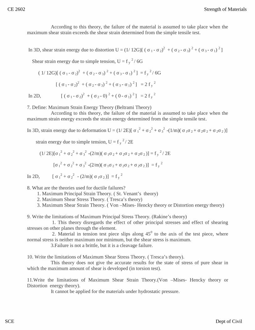
According to this theory, the failure of the material is assumed to take place when themaximum shear strain exceeds the shear strain determined from the simple tensile test.
In 3D, shear strain energy due to distortion U = (1/ 12G)[ ( σ 1 - σ 2)2 + ( σ 2 - σ 3)
2 + ( σ 3 - σ 1)2 ]
Shear strain energy due to simple tension, U = f y2 / 6G
( 1/ 12G)[ ( σ 1 - σ 2)2 + ( σ 2 - σ 3)
2 + ( σ 3 - σ 1)2 ] = f y
2 / 6G
[ ( σ 1 - σ 2)2 + ( σ 2 - σ 3)
2 + ( σ 3 - σ 1)2 ] = 2 f y
2
In 2D, [ ( σ 1 - σ 2)2 + ( σ 2 - 0) 2 + ( 0 - σ 1)
2 ] = 2 f y2
7. Define: Maximum Strain Energy Theory (Beltrami Theory)According to this theory, the failure of the material is assumed to take place when the
maximum strain energy exceeds the strain energy determined from the simple tensile test.
In 3D, strain energy due to deformation U = (1/ 2E)[ σ 12 + σ 2
2 + σ 32 -(1/m)( σ 1σ 2 + σ 2σ 2 + σ 2σ 2 )]
strain energy due to simple tension, U = f y2 / 2E
(1/ 2E)[σ 12 + σ 2
2 + σ 32 -(2/m)( σ 1σ 2 + σ 2σ 2 + σ 2σ 2 )] = f y
2 / 2E
[σ 12 + σ 2
2 + σ 32 -(2/m)( σ 1σ 2 + σ 2σ 2 + σ 2σ 2 )] = f y
2
In 2D, [ σ 12 + σ 2
2 - (2/m)( σ 1σ 2 )] = f y2
8. What are the theories used for ductile failures?1. Maximum Principal Strain Theory. ( St. Venant’s theory)2. Maximum Shear Stress Theory. ( Tresca’s theory)3. Maximum Shear Strain Theory. ( Von –Mises- Hencky theory or Distortion energy theory)
9. Write the limitations of Maximum Principal Stress Theory. (Rakine’s theory)1. This theory disregards the effect of other principal stresses and effect of shearing
stresses on other planes through the element.2. Material in tension test piece slips along 450 to the axis of the test piece, where
normal stress is neither maximum nor minimum, but the shear stress is maximum.3.Failure is not a brittle, but it is a cleavage failure.
10. Write the limitations of Maximum Shear Stress Theory. ( Tresca’s theory).This theory does not give the accurate results for the state of stress of pure shear in
which the maximum amount of shear is developed (in torsion test).
11.Write the limitations of Maximum Shear Strain Theory.(Von –Mises- Hencky theory orDistortion energy theory).
It cannot be applied for the materials under hydrostatic pressure.
SCE Dept of Civil
CE 2602 Strength of Materials

12. Write the limitations of Maximum Strain Energy Theory. ( Beltrami Theory).This theory does not apply to brittle materials for which elastic limit in tension and in
compression are quite different.
13. Write the failure theories and its relationship between tension and shear.
1. Maximum Principal Stress Theory. ( Rakine’s theory) ζ y = f y
2.Maximum Principal Strain Theory. ( St. Venant’s theory) ζ y = 0.8 f y
3. Maximum Shear Stress Theory. ( Tresca’s theory) ζ y =0.5 f y
4.Maximum Shear Strain Theory ( Von– Mises - Hencky theory or Distortion energy theory)ζ y= 0.577 f y
5. Maximum Strain Energy Theory. ( Beltrami Theory) ζ y= 0.817f y .
14. Write the volumetric strain per unit volume.f y
2 / 2E
20. Define : Octahedral StressesA plane, which is equally inclined to the three axes of reference, is called octahedral
plane. The normal and shearing stress acting on this plane are called octahedral stresses.
τ oct = 1/ 3 √ ( σ 1 - σ 2)2 + ( σ 2 - σ 3)
2 + ( σ 3 - σ 1)2
21. Define: Plasticity ellipse.The graphical surface of a Maximum Shear Strain Theory (Von –Mises- Hencky theory
or Distortion energy theory) is a straight circular cylinder. The equation in 2D is
σ 12 - σ 1σ 2 + σ 2
2 = f y2 which is called the Plasticity ellipse
SCE Dept of Civil
CE 2602 Strength of Materials

UNIT : V
1. What are the assumptions made in the analysis of curved bars?1.Plane sections remain plane during bending.2.The material obeys Hooke’s law.3.Radial strain is negligible.4.The fibres are free to expand or contract without any constraining effect from the
adjacent fibres.
2. Write the formula for stress using Winkler-Bach theory? = M 1 + R2 y
R x A h2 R + y
where = Bendind stress (i.e., b )M = Bending moment with which the bar is subjectedR = Radius of curvature of curved bar or it is the distance of axis of curvature from
centroidal axis.A = Area of cross-sectionh2 = is a constant for a cross-section
= 1 y2dAA 1 + y
R
3. Define unsymmetrical bending.If the plane of loading or that of bending, does not lie in (or parallel to) a plane that
contains the principal centroidal axisof the cross-section, the bending is called unsymmetricalbending.
4. What are the reasons for unsymmetrical bending?1.The section is symmetrical but the load line is inclined to both the principal axes.2.The section itself is unsymmetrical and the load line is along the centroidal axis.
5. How will you calculate the stress due to unsymmetrical bending?
=Iuu
vMv
Ivv
uMu ..
where u = x cos + y sin v = y cos - x sin
6. How will you calculate the distance of neutral axis from centroidal axis.
SCE Dept of Civil
CE 2602 Strength of Materials

y0 = - R x h2
R + h2
-ve sign shows that neutral axis is below the centroidal axis.
7. How will you calculate the angle of inclination of neutral axis with respect to principal axis? = tan-1 IUU tan
IVV
8. Write the formula for deflection of a beam causing unsymmetrical bending.
= KWl3 sin2 + cos2E I2
vv I2uu
Where K = a constant depending upon the end conditions of the beam and the position ofthe load along the beam
l = length of the beam = angle of inclination of load W with respect to VV principal axis
9. How will you calculate the resultant stress in a curved bar subjected to direct stress andbending stress.
r = o + b
where o = Direct stress = P/Ab = Bending stress
10. How eill you calculate the resultant stress in a chain link.r = o + b
where o = Direct stress = P x sin 2A
b = Bending stress
11. What is shear centre or angle of twist?The shear centre for any transverse section of the beam is the point of intersection of
the bending axis and the plane of the transverse section.
12. Who postulated the theory of curved beam?Winkler-Bach postulated the theory of curved beam.
13. What is the shape of distribution of bending stress in a curved beam?The distribution of bending stress is hyperbolic in a curved beam.
14. Where does the neutral axis lie in a curved beam?The neutral axis does not coincide with the geometric axis.
15. What is the nature of stress in the inside section of a crane hook?Tensile stress
16. Where does the maximum stress in a ring under tension occur?The maximum stress in a ring under tension occurs along the line of action of load.
17. What is the most suitable section for a crane?
SCE Dept of Civil
CE 2602 Strength of Materials

Trapezoidal section.
18. What is pure bending of a beam?When the loads pass through the bending axis of a beam, then there shall be pure
bending of the beam.
19. How will you determine the product of inertia.The product of inertia is determined with respect to a set of axes which are perpendicular toeach other.The product of inertia is obtained by multiplying each elementary area dA by its co-ordinates x and y and integrated over the area A.
IXY = xy dA
20. Define principal moment of inertia.The perpendicular axis about which the product of inertia is zero are called
“principal axes” and the moments of inertia with respect to these axes are called as principalmoments of inertia.
The maximum moment of inertia is known as Major principal moment of inertia andthe minimum moment of inertia is known as Minor principal moment of inertia.
SCE Dept of Civil
CE 2602 Strength of Materials
PART – B
1. Calculate the strain energy stored in a cantilever beam of 4m span, carrying a point load 10KN at free end. Take EI = 25000 KNm2.
2. State and prove Maxwell’s reciprocal theorem.3. State and prove Castigliano’s theorem.4. ii) Find the deflection at the mid span of a simply supported beam carrying an uniformly
distributed load of 2KN/m over the entire span using principle of virtual work. Take span =5m; EI = 20000 KNm2.
5. A plane truss is shown in Fig. Find the horizontal deflection of joint B by virtual workmethod.
Area of cross section = 20000mm2 (comp. members)Area of cross section = 10000mm2 (tension members)E = 200 KN/mm2
6. A continuous beam is shown in Fig. Draw the BMD and SFD indicating salient points.
7. For the fixed beam shown in Fig. Draw BMD and SFD.
8.Using Euler’s theory, find the buckling load for fixed-free column9.Using Euler’s theory, find the buckling load for fixed-fixed column
SCE Dept of Civil
CE 2602 Strength of Materials

10.Using Euler’s theory, find the buckling load for hinged-hinged column11.Using Euler’s theory, find the buckling load for fixed-hinged column .12.Find the ratio of buckling strength of a solid column to that of a hollow column of the same
material and having the same cross sectional area. The internal diameter of the hollow column ishalf of its external diameter. Both the columns are hinged and the same length.
13..Determine the principal stresses and principal directions for the following 3D- stress field.9 6 3
[ ] = 6 5 23 2 4
14. In a two dimensional stress system, the direct stresses on two mutually perpendicular planes areand 120 N/mm2. In addition these planes carry a shear stress of 40 N/mm2. Find the value of atwhich the shear stain energy is least. If failure occurs at this value of the shear strain energy,estimate the elastic limut of the material in simple tension.
Take the factor of safety on elastic limit as 3.15. Find the centroidal principal moments of inertia of a equal angle section 80mm x 80mm x 10mm.
16.A curved bar of rectangular cross section 60mm wide x 75mm deep in the plane of bendinginitially unstressed, is subjected to a bending moment of 2.25 KNm which tends to straighten thebar. The mean radius of curvature is 150mm. Find: (i) position of neutral axis (ii) the greatestbending stress.17. A bolt is under an axial thrust of 9.6 KN together with a tranverse force of 4.8 KN. Calculate thediameter of the bolt according to failure theories.18. The inside and outside diameters of a cast iron cylinder are 240mm and 150mm resp. If theultimate strength of cast iron is 180 MN/m2, find the internal pressure which could cause ruptureaccording to failure theories.19. Calculate the safe compressive load on a hollow cast iron column (one end fixed and other endhinged) of 150mm external diameter, 100mm internal diameter and 10mm length. Use Euler’sformula with a factor of safety of 5 and E = 95 GN/m2.20. Calculate the thickness of a metal necessary for a cylindrical shall of internal diameter 160mmto withstand an internal pressure of 25 MN/m2, if maximum tensile stress is 125 MN/m2.
SCE Dept of Civil
CE 2602 Strength of Materials


Reg. No. :
B.E./B.Tech. DEGREE EXAMINATION, APRIL/MAY 2010
Fourth Semester
Civil Engineering
CE2252 — STRENGTH OF MATERIALS
(Regulation 2008)
Time: Three hours Maximum: 100 Marks
Answer ALL Questions
PART A — (10 × 2 = 20 Marks)
1. A beam of span 4 m is cantilever and subjected to a concentrated load 10 kN at
free end. Find the total strain energy stored. Take the Flexural rigidity is EI.
2. Write down Maxwell’s reciprocal theorem.
3. A fixed beam of span ‘L’ is subjected to UDL throughout w/m. What is end
moments and moment at the centre?
4. Draw BMD for a propped cantilever beam span ‘L’ subjected to UDL
throughout w/m.
5. Define core of a section and draw the same for a circular section.
6. Write Rankine’s equation for column.
7. Define principal plane and principal stress.
8. State the principal stress theory of failure.
9. What is ‘fatigue strength’ and ‘endurance ratio’ in a fatigue testing of material?
10. Write the Winkler-Bach formula for a curved beam.
Question Paper Code: E3047
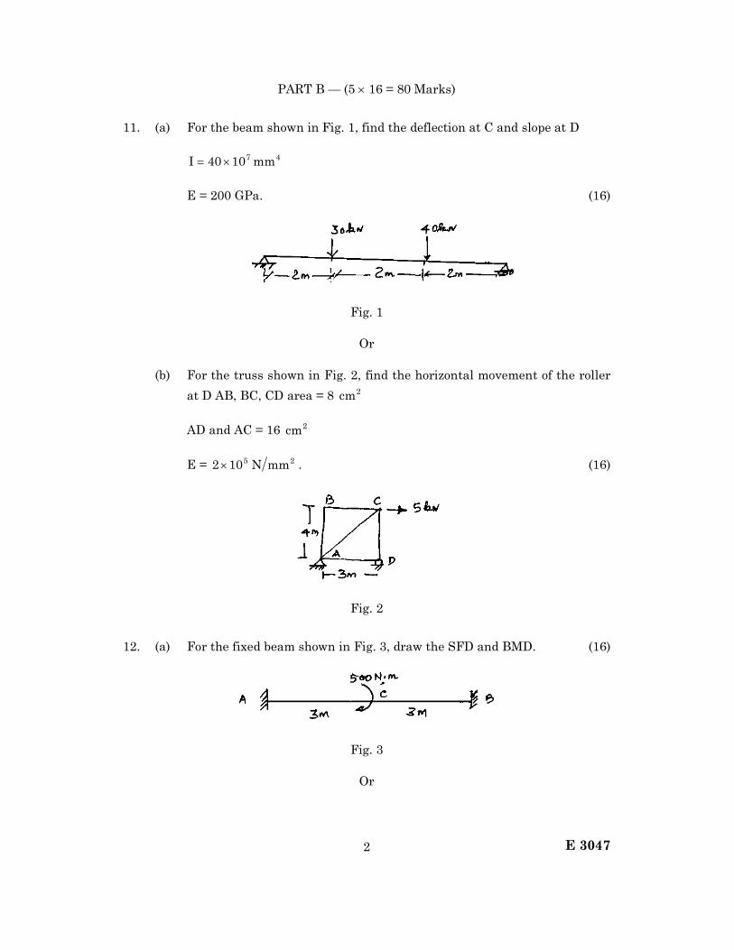
E 3047 2
PART B — (5 × 16 = 80 Marks)
11. (a) For the beam shown in Fig. 1, find the deflection at C and slope at D
47mm1040I ×=
E = 200 GPa. (16)
Fig. 1
Or
(b) For the truss shown in Fig. 2, find the horizontal movement of the roller
at D AB, BC, CD area = 8 2cm
AD and AC = 16 2cm
E = 5102 × 2mmN . (16)
Fig. 2
12. (a) For the fixed beam shown in Fig. 3, draw the SFD and BMD. (16)
Fig. 3
Or

E 3047 3
(b) For the continuous beam shown in Fig. 4, draw SFD and BMD all the
supports are at same level. (16)
Fig. 4
13. (a) (i) Derive the Euler’s equation for column with two ends fixed. (8)
(ii) A circular bar of uniform section is loaded with a tensile load of
500 kN. The line of action of the load is off the axis of the bar by
10 mm. Determine the diameter of the rod, if permissible stress of
the material of the rod is 140 2mmN . (8)
Or
(b) Find the greatest length of a mild steel rod of 30 mm × 30 mm which can
be used as a compressive member with one end fixed and the other end
hinged. It carries a working load of 40 kN. Factor of safety = 4,
α = 75001 and 300C =σ 2mmN . Compare the result with
Euler. E = 5102 × 2mmN . (16)
14. (a) (i) Briefly explain spherical and deviatory components of stress tensor.
(6)
(ii) Explain the importance of theories of failure. (4)
(iii) For the state of stress shown in Fig. 5, find the principal plane and
principal stress. (6)
Fig. 5
Or
(b) A circular shaft has to take a bending moment of 9000 N.m and torque
6750 N.m. The stress at elastic limit of the material is 610207 × 2mN
both in tension and compression. E = 610207 × KPa and µ = 0.25.
Determine the diameter of the shaft, using octahedral shear stress theory
and the maximum shear stress theory. Factor of safety : 2. (16)
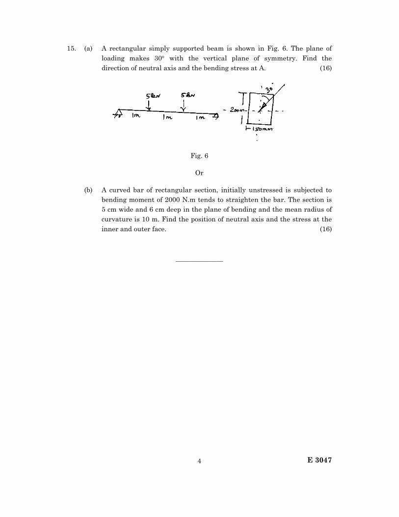
E 3047 4
15. (a) A rectangular simply supported beam is shown in Fig. 6. The plane of
loading makes 30° with the vertical plane of symmetry. Find the
direction of neutral axis and the bending stress at A. (16)
Fig. 6
Or
(b) A curved bar of rectangular section, initially unstressed is subjected to
bending moment of 2000 N.m tends to straighten the bar. The section is
5 cm wide and 6 cm deep in the plane of bending and the mean radius of
curvature is 10 m. Find the position of neutral axis and the stress at the
inner and outer face. (16)
———————

I
I
I
Reg. No. :
M 0454
B.E./B.Tech. DEGREE EXAMINATION, NOVEMBER/DECEMBER 201r
FOURTH SEMESTER
CN'IL ENGINEERING
CET255 STRENGTH OI MATERIAI"S - [
. (REGIII,ATION 2OO?)
Time : Three hours Maximum : 100 marks
Anlwer ALL queotions.
. PART A - (10 x 2 = 20 marks)
l. State Maxwell's leciprccal theore&.
2. What is fleant by Btrain enelgy?
3. How will you find th€ reactioa at the plop of a cantilewr bean propped at thefree end?
4. State the advaltages of a frted bean ovel simply supported beam?
5- What is neent by equivalent length of s columrl?
6. Sketch the core of a circular section of diameter 'd',
7. Name the important theories offailures.
. 8. Define the term voludetric etlain.
9. Write down the expreeeion for Wiol<ler'Bach foroula.
10. Defiie endurance limit.
PARTB-(5 x 16 = 80 marks)
ll. U8ing Caetigliano's tbeoreo, dete.mine the Elope and d€flection at theoverhanging enl4 C of a sirnply suppoded beaE AB of span 'U with a ovelharg
IBc oflensth ! iubiect to a clockwise moloent ofM at the &ee end C.-3
Or

14.
12. A tension bar 5 m long is made up of two parts. 3 m of its length has a crosssectional area of 1000 mm2 while the remaining 2 m has a cross aectional areaof 2000 mm2. An axial load of 100 kN is gradually applied. Find the total strainenergy stored in the bar and cornpare this value with that.obtained in a
uniform bar of same length and hsving the same volume under the same load.TakeE=200kN/mmr.
13. Draw the shear folce and bending moment diagtam for a ffxed beam AB ofspan 6m carrying a urrifoimly distributed load of 6 kN/m over the left half o{the spa[.
Or
A continuous beam ABC of uniform section has the span AB = BC = 6 m. It ishxed at A and simply supported at C. TTre beam is carrying a uniformlydistdbuted load of 6 kN/m throughout the span AB and a concentrated load of20 kN at the mid span of BC. Analyee the beam by the theorem of tbreemoments and draw the shear force and bending moment diagram.
A hollow circular short column of 250 mm exte
20. A central horizontal section of a hook is a symmetrical trapezium 60 mln deep.the inner width being 60 mm and the outer \I/iatfl SO rn_.--p"ii_ot"" tfr"extreme intensitie€ of stress when the hool carries a load of B0 Urt iir" f""aline passing 40 mrn from the inside eclge of the .u"ti"n ^"a-tiu'"".,i"" otcurvaturc being in the load line. ,Also plot the stress ai"t.it"tio"-^".o".. tfl"
secl ion.

R€g, No, !
G 0287
B.E./B.Tech. DEGREE EXAMINATION, NOVEMBER/DECEMBER 2010
TIIIRD SEMESTER
CTVIL ENGINEEMNG
CE12O2 STRENGTII OF MATSRIAI,S _ I
(REGUI,ATION 2OO7)
Time : Tbree hours Maximum : 100 narks
Answer ALL queatione
PARTA-(10 x 2 = 20 marl<e)
1. Defire tho teres Poi6soa'8 ratio and Bulk Modulug'
2. Writ€ the expreBsion foa fiading strain energr ilue to shear'
3. Sketch the beniling domeat ilisgtam for a simply eupported beam subjecteil to
a uniforaly distributeil load S'over the entire spa!'
4. What is tbe relationship between intotrsity of loading a.n, d doflection at a:ry
point of a beala?
6. What i8 a bead ofudform etreagt'h?
6. What i6 the maxieuo deOoction in a cantilver beam of spao 'l subjecto'l to a
udforoly itistributeil load over the entire epaa?
?. How will you obtain Polar moment ofilertia ofa hollow circular sbaft?
8. Writ€ the foruula for ffndiog deflection of a doao coiled helical apriag'
9. Difietgutiate deteroiaate ald hdetor8inato trur!g3'
10. Wh€u methoil of rectionr is preferred for truss analysis?
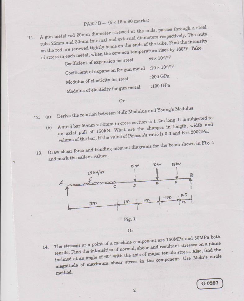
PARTB-(5x16=80matks)
11. A gun metal rod 20mm diameter screwe'l at tho u"d"' pu"":-1fl:yh o
" :*;r*';:qti"l+ng#*t**;;5*r*#of streas ia each metal' when tr
Co€Eciedt of erpaaBioa for stael :6 x 10⁶/"F
Coe6cielt of exparrsiolfor guometal :10 x 104/"F
Modulua of elasticity for ateel :200 GPa
Modulus of elasticity for gua aetal :100 GPa
Or
(a) Derive tbe telatioa betweea Bulk Mo<lulue and Young'e Modulue'
J r*s:rr* lffi"*:i"l"i*[**: r#.f'$#volume of the bar' if the value o
Dranv ghear force arld betrdirrg monent diagEarne for the bearn ehowo. ia Fig' 1
arril roark t}.e salieot valueg'13.
tgp ItL,)
Fig l
Or
FJ#,#f{f -+"j":""":{H:fi,{#ift ffi :nethod.
14.

16.
15, Three beame have the sarrle length, tle Barne a]lowable stress anil ths sane
beDding momeDt. Tte crosg section of the beame are a equare of siclee 'a', a
rectaagle of width $', dept.L twica the widt'h 'b' and a qircle of diameter 'd''
Determins the retios ofweighta of the circulgr and the rectslgular beams wit'h
respect to tho square b€am'
t7.
Or
A simply supportad b€am of span 9n ie subject€d to a poird lo''l of 25kN at 6m
ffom the left end. Take I = 62 I 1S oma aad E as 200GPa Detersire the
do0ection uoder tho loaal poiDt by coajugat€ beam mothocl'
A solid alunriniura sha.ft 1m long and of somm diamet€r is to be replaced by a
hollow ehafi of the esme length aad same outside dismetar, so t'hat the hollow
ehaft could carry the same torque aad haa t'he same aagle of twist' What must
be the inaer diameter of the hollow shaft. Tal<e modulur of igiclity for
alqminiurn ae 28GPa a:rd that for steel as 85GPa'
Or
A! open coil helical epriag made up of 10mo diaueter wiro and of meaa
diamet€r 100lor! hae 12 coils, 6ngle of helix being 16"' Deter4ins the axtul
deflection anil the iltenaitiea ofbeuding and eheal eheesee under ar axial load
of ,$0N. Take C as 80GPa and n as 200GPa'
Determiae the forces in the various members oftlrc tiu6s showl in Fig'2'
FiS. 2.
Or
18.
19.
-l

20. Det€rmile the forceg ia the varioug m€llbere ofth€ truse shown in Fig,3
h,
l--- 'z]4----+--D*+-
FiC. 3

Reg. No. :
B.E./B.Tech. DEGREE EXAMINATION, NOVEMBER/DECEMBER 2011.
Fourth Semester
Civil Engineering
CE 2252 — STRENGTH OF MATERIALS
(Regulation 2008)
Time : Three hours Maximum : 100 marks
Answer ALL questions.
PART A — (10 × 2 = 20 marks)
1. State Castigliano’s first theorem.
2. Calculate the strain energy stored in the beam shown in fig. 1. EI constant.
Fig. 1
3. For the fixed beam shown in fig. 2 what is the fixed end moment at A and B.
Fig. 2
4. For the propped cantilever shown in fig. 3 draw the BMD (qualitative).
Fig. 3
5. State any two assumptions made in the derivation of Euler’s formula for long columns.
Question Paper Code : 55241
W
L
W
P A a b
L
W
L/2 L/2 421 4
21 4
21
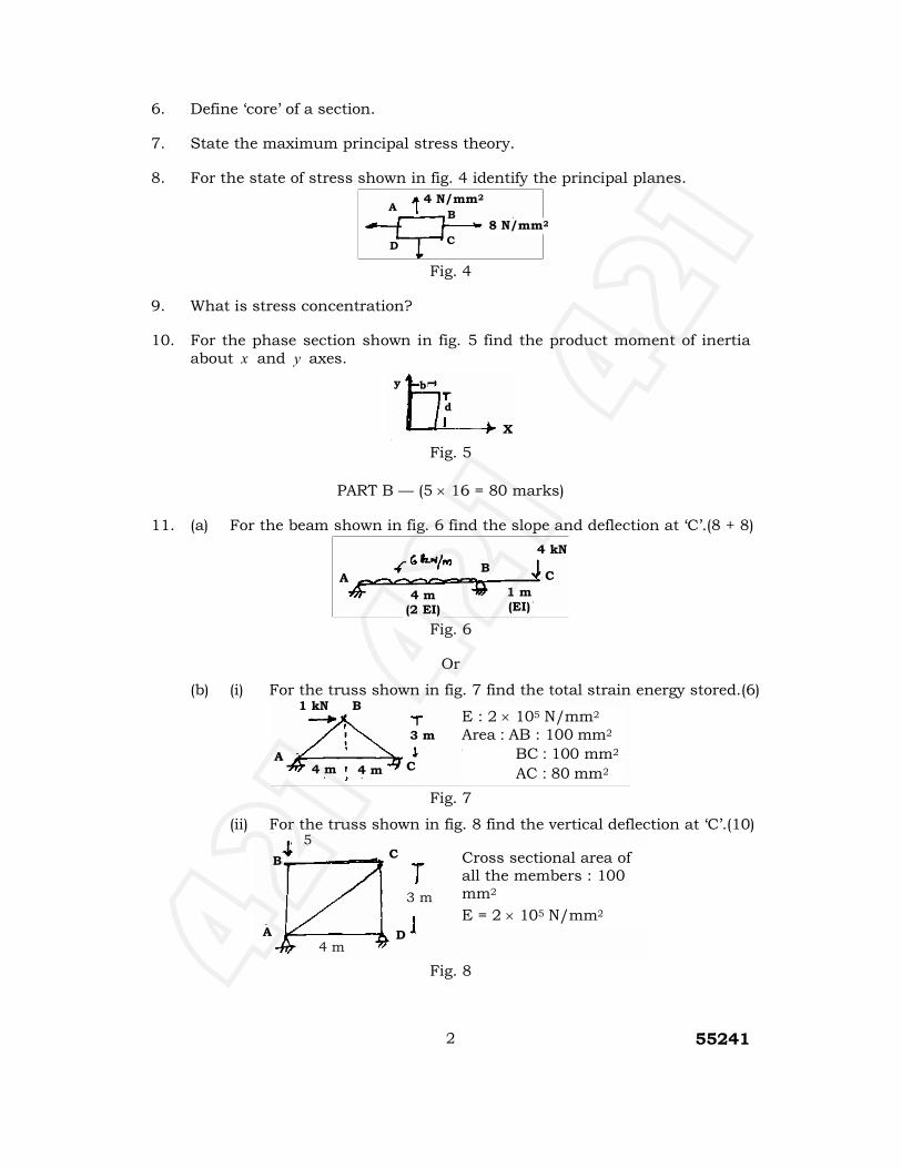
55241 2
6. Define ‘core’ of a section.
7. State the maximum principal stress theory.
8. For the state of stress shown in fig. 4 identify the principal planes.
Fig. 4
9. What is stress concentration?
10. For the phase section shown in fig. 5 find the product moment of inertia about x and y axes.
Fig. 5
PART B — (5 × 16 = 80 marks)
11. (a) For the beam shown in fig. 6 find the slope and deflection at ‘C’.(8 + 8)
Fig. 6
Or
(b) (i) For the truss shown in fig. 7 find the total strain energy stored.(6)
Fig. 7
(ii) For the truss shown in fig. 8 find the vertical deflection at ‘C’.(10)
Fig. 8
8 N/mm2
4 N/mm2
B
C D
A
X
d
y b
4 kN
1 m (EI)
A B
C
4 m (2 EI)
C
3 m
B 1 kN
4 m 4 m A
E : 2 × 10⁵ N/mm2
Area : AB : 100 mm2
BC : 100 mm2
AC : 80 mm2
4 m
Cross sectional area of all the members : 100 mm2
E = 2 × 10⁵ N/mm2
A
C
D
3 m
5 kN B
421 4
21 4
21
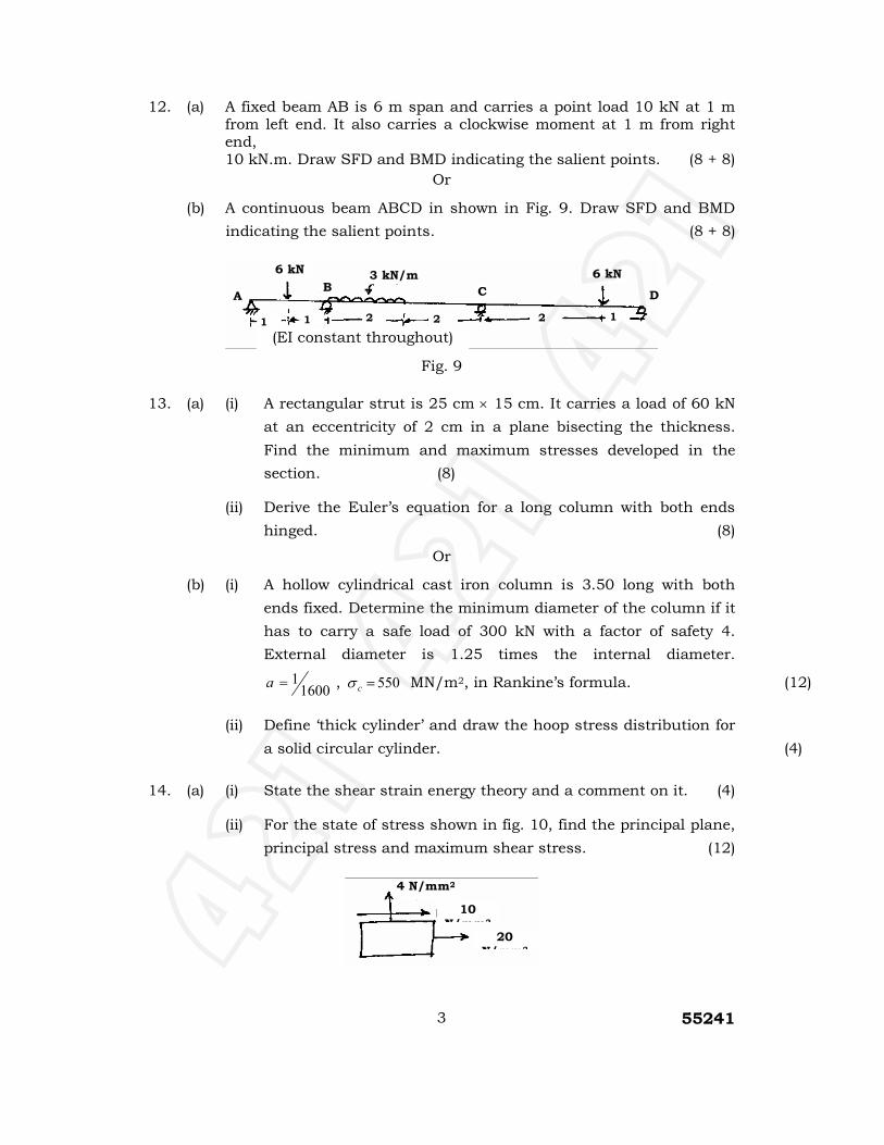
55241 3
12. (a) A fixed beam AB is 6 m span and carries a point load 10 kN at 1 m from left end. It also carries a clockwise moment at 1 m from right end, 10 kN.m. Draw SFD and BMD indicating the salient points. (8 + 8)
Or
(b) A continuous beam ABCD in shown in Fig. 9. Draw SFD and BMD
indicating the salient points. (8 + 8)
Fig. 9
13. (a) (i) A rectangular strut is 25 cm × 15 cm. It carries a load of 60 kN
at an eccentricity of 2 cm in a plane bisecting the thickness.
Find the minimum and maximum stresses developed in the
section. (8)
(ii) Derive the Euler’s equation for a long column with both ends
hinged. (8)
Or
(b) (i) A hollow cylindrical cast iron column is 3.50 long with both
ends fixed. Determine the minimum diameter of the column if it
has to carry a safe load of 300 kN with a factor of safety 4.
External diameter is 1.25 times the internal diameter.
16001=a , 550=cσ MN/m2, in Rankine’s formula. (12)
(ii) Define ‘thick cylinder’ and draw the hoop stress distribution for
a solid circular cylinder. (4)
14. (a) (i) State the shear strain energy theory and a comment on it. (4)
(ii) For the state of stress shown in fig. 10, find the principal plane,
principal stress and maximum shear stress. (12)
(EI constant throughout)
3 kN/m
D
1 m
2 m
2 m
2 m
1 1
6 kN 6 kN C B
A
20 N/mm2
10 N/mm2
4 N/mm2
421 4
21 4
21

55241 4
Fig. 10
Or
(b) In a material the principal stresses are 50 N/mm2, 40 N/mm2 and
–30 N/mm2. Calculate the total strain energy, volumetric strain
energy, shear strain energy and factor of safety on the total strain
energy criterion if the material yields at 100 N/mm2. (4 × 4 = 16)
15. (a) Fig. 11 shows a frame subjected to a load of 3.4 kN find the resultant stress at A and B. (16)
Fig. 11
Or
(b) A beam of T-section (flange : 100 × 20 mm, web: 150 mm × 10 mm) in 3 m in length and simply supported at ends (Fig. 12). It carries a load of
2.2 kN inclined 20° to the vertical and passing through the centroid of the section. Calculate the maximum tensile stress and maximum compressive stress. Also find the position of the neutral axis.(7 + 7 + 2)
Fig. 12
48 mm
3.4 kN
3.4 kN
120 mm
A
18 mm
(Beam loaded centrally, Load not shown)
Y
2.2 kN
46.40 mm
X X
Y
3 m
421 4
21 4
21

55241 5
————––––——
421 4
21 4
21

