chapter xi cost analysis of multiple funicular shell...
TRANSCRIPT
CHAPTER XI
COST ANALYSIS OF MULTIPLE FUNICULAR SHELL AND CONVENTIONAL
REINFORCED CEMENT CONCRETE FOUNDATIONS
11.1 Comparison of Costs between Multiple Funicular Shell
Footings and Conventional Reinforced Concrete Footings
11.1.1 Necessity of the study
The structural efficiency alone may not
result in the new foundation methods being adopted by
engineers. Ease of construction and reduced cost only will
enable the conventional type to be replaced by a new one.
Therefore, a study was undertaken to determine the relative
costs of multiple funicular shell footing and conventional
plain reinforced concrete footing at the usual ranges of
allowable bearing capacity. Since the dimensions of the
funicular shell footings consisting of 4 shells were fixed
in this study, the conventional footings of same dimensions
out the relative costs. For
4.1t/m 2 (40kH/m 2 ) to 9.2t/m 2
were considered for working
various soil pressures from
(90kn/m 2 ) the dimensions and reinforcements for the
connecting beams and edge beams of the multiple funicular
shell footings and thickness and reinforcements for th~
plain footing were worked out for arriving at their costs as
given in Tables 11.land 11.2
147

11.1.2 Design details
11.1.2.1 Multiple funicular shell footing
The central connecting beams were designed as
cantilevers acted upon by a uniform soil reaction acting on
the triangular areas ABC, and EFG and on the rectangle
EABF. The edge beams of the footings were designed as
cantilevered from the ends of the central connecting beams,
the design bending moments being that due to the uniform
soil reaction acting on the area DEC (Fig.8.1). The
structural designs were carried out as per 1.5.456-1978.
The grade of concrete used for design is 1'115
and HYSD steel
bars (grade Fe 415). The width of the connecting beams was
30cm and that of the beams along the edges, 15cm. A cover
of 6cm was provided at the bottom of all the beams. The
connecting
portion, and
beams were of constant depth for the central
then of sloping section to be compatible with
the top of the edge beams at their ends. The columns of
the structure Ivere assumed to have a cross section of 30cm
x 30cm and to start at the junction between the central
connecting beams. The edge beams vie r e sloping from the
junction bet I-lee n them and the connecting beams to the
corners of the unit, the slope being 1 : 10. The details of
the dimensions of the beams and the reinforcements \>/ere as
given in To~le 11.1.
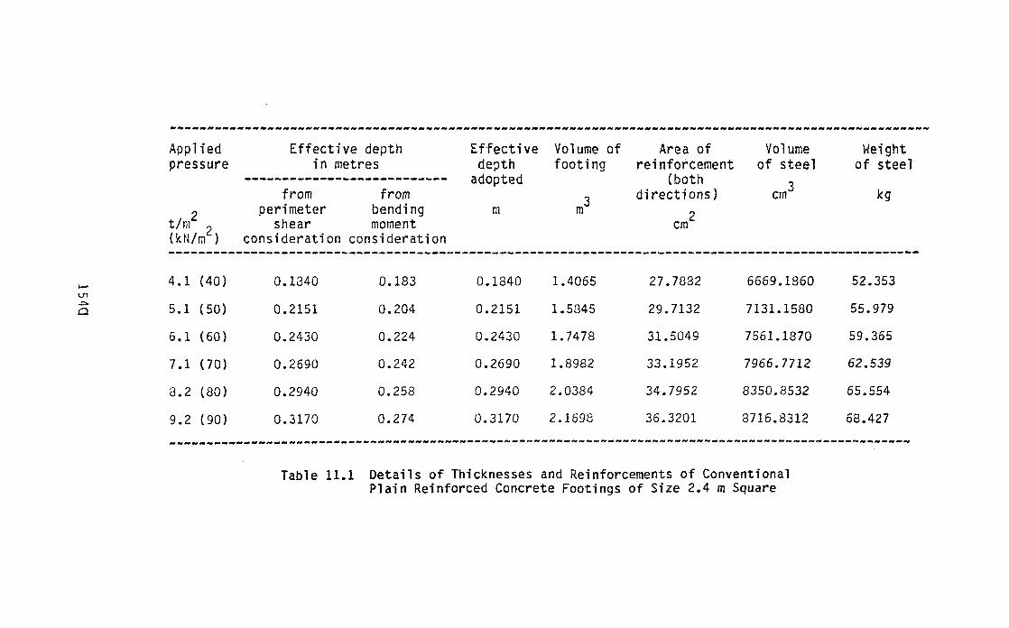
11.1.2.2 Plain reinforced concrete footing
The design of the plain concrete footings were
also done as per I.S.456-1978.
148
The concrete of grade 1,1 15
and HYSD bars (grade Fe 415) were adopted for design
purposes. The design dimensions of the footings have been
obtai ned based on considerations of flexural and perimeter
shear failure. A cover of 6cm 'rIa s given at the bottom of
tile footings. The details of the footings and the
reinforcements for the various a11 O~I ab 1 e pressures on the
soil "/ere as given in Table 11. 2.
11.1.3 Cost estimates
For the connecting beams and the edge beams of
multiple funicular shell footings, shuttering work of mild
steel sheets of suitable thicknesses can be fabricated and
used wi th great economy and ease. Since the shuttering can
be used a number of t i [,leS for a 1 arge housing complex, the
cost per unit of footing \'i i 11 be reduced to a minimum. The
heigl1t of the shuttering can be uniform, commensurate 'vI i th
the total depth of the connecting beams of the most heavily
loaded footing of the proposed structre. Thus, the form
work of the same dimensions can be used for all the
footings.
For the plain footings, no shuttering work is
required.
The cost of MIS grade concrete prepared, placed in
position, compacted, and cured properly was worked out to be
Rs 633/m 3 and that of lkg of HYSD bars (grade Fe 415) bent
and tied as per designs in place as Rs 7.12 as per Kerala
Stat e Pub 1 i c \10 r ks De par men t rat e s as 0 n 1. 10 • 1986 \'Ii t h
all 0'11 a11 ce for can veyan ceo f mat eria1 s for 20 kill. The serat e s
149
were taken for arriving at the total cost of multiple
funicular shell footings and plain footings.
11.1.4 Comparsion of costs and savings in materials between
the two types of footings
The details of the costs of and the quantities for
plain footings and mUltiple funicular shell footings were as
given in Table 11.3. The savings in the quantity of
concrete required for the latter progressively increased
2from 34 to 49% for contact pressures varying from 4.1t/m to29.2t/m. There iJere savings in the quantity of steel for
multiple funicular shell footing for low pressures. But the
requirments of steel for the foundations with larger contact
pressures iJere higher than that for the conventional
footings. However, as far as the costs were concerned,
the rei sal Vi ay s areduct ion inc 0 s t s for the she 11 f 0 0 tin gs
over the plain reinforced concrete footings at the
corresponding contact pressures. It was observed that the
maxmimum savings in cost of 23% was obtained for the shell
2footing for a contact pressure of 5.1t/m •
11.2 Comparison of Costs between Multiple Funicular Shell
Rafts and Conventional Reinforced Concrete Raft
The functions of the multiple funicular shell raft
and the conventional reinforced concrete raft are the same.
Suitably connected funicular shells replace the slab of the
latter. For comparison of costs between the two t;pes of
rafts, tile structural designs \'Jere carried out as per 1.S
456- 1978, assuming uniform contact pressures acting on
150
them. grade of concrete used for designs is M and15HYSD bars (grade Fe 415) as tension and shear
reinforcements. The esimates of costs of the rafts for
various pressures have been made based on the Kerala State
Public Works Department rates as on 1.10.1986.
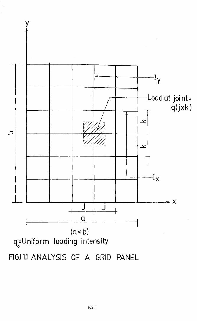
11.2.1 Design of multiple funicular shell rafts
For the design of the connecting beams of the
raft, the design moments and shear forces were determined
using the theory of Salvadori (1967) for a rectangular grid.
With reference to fig.11.1
k = q{j.k) . . (11.l)
Taking the first term of the Furier Series
expansion for uniform contact pressure qo'
16 rrx 7r.yq = -;2- qo Sin---- Sin---- • • (11.2)
a b
Assuming the follo\'Jing solution of equation 11.1
1\x 7\yz =
aSin
b
equation 11.1 is solved to give
Za1
-------------------------a 4 k I
1 + (---) (---) ( __l_)b j I x
151
• • (1 1.4)

ilzMx = -Eel x -~;~- =
7rx 7\Yq a2k 5in---- 5in---o a b
-----------------------~a 4 k I
1 + (--_) ( ) ( __ l_)b j Ix
•• (11.5)
16 ~Q~~ cos-~~- sin-~~-
;"3 a 4 k I a b1 + (---) (---) ( __ l_)
b j I x
•• (11.6)
---izN = -E Iy c y ox 2
= 16 ~Q~~~ cos-~~--47r b 4 k I a
1 + (---) (---) (--~-)a j Iy
• •
lfY5in----
b
(11.7)
03 Z 16 ~Q~~ cos-~:- ITYVy = -Eel y ~y-3 = -3 5in----
o 7f b 4 j Ix a b1 + (---) (---) (----)
a k Iy
• • (1 1.8)
For multiple funicular shell rafts consisting of 4
shells (Fig 11.2) the maximum bending moments and shear.
forces acting on the connecting beams were calcutated for
uniform contact pressures from 4.1tlm2 to 9.2tlm 2 using a
computer programme from equations 11.5 and 11.6. Here,
j=k I =1 =1 since the raft panels were squares. The, x y
design bending moments and shear forces obtained were as
given in Table 11.4. The cover adopted for all the beams
was 6cms at bottom, 2cm each on sides and at top. Two, 8mm
152

di aIi1 e t er HYSDba r s \', ere
each connecting beam.
legged stirrups of 6mm
provided as stirrup holders for
iIi i ni mu111 she ar rei nfor cem en t s oftW0
diameter HYSD bars at 19.5cm
intervals were provided for each connecting beam. The
details of dimensions of the beams and the reinforcements
were as given in Table 11.5.
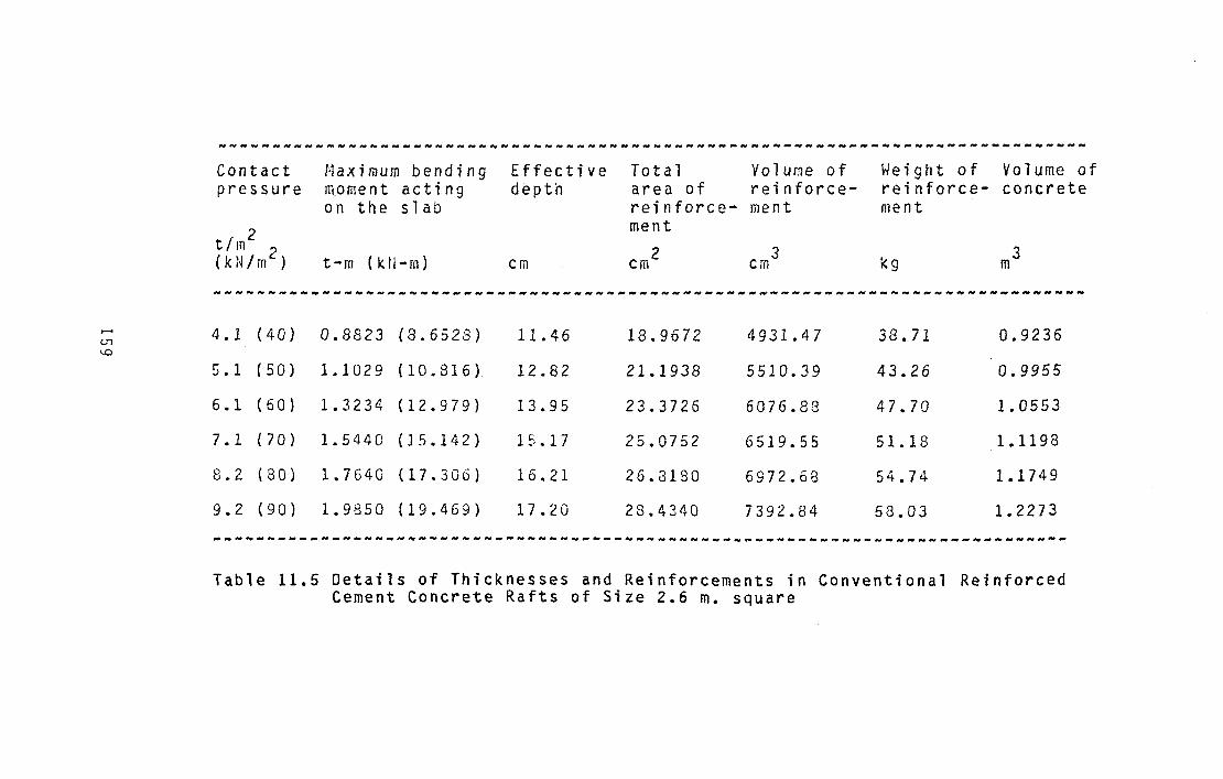
11.2.2 Design of conventional reinforced concrete rafts
The raft slabs were designed for maximum bending
moments of 0.032 q o12 where qo' is the corresponding uniform
contact pressure and 1, the span. A cover of 6CM was given
for the raft slabs at their bottom. The same area of
reinforcements was provided in both the directions in the
slab. The details of dimensions and reinforcements of the
rafts were as given in Table 11.6.
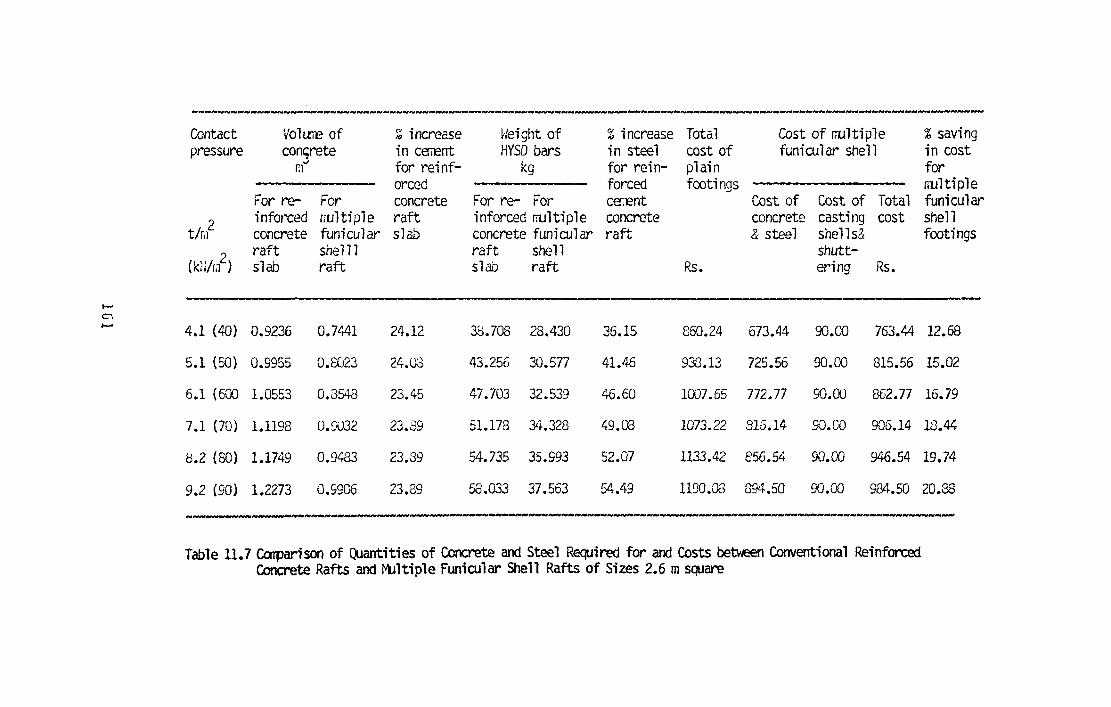
11.2.3 Estimation of costs
For the purposes of estimation, the actual areas
of tensile reinforcements obtained as per design were taken
into account. The cost of the four funicular shells and the
connecting ~eams were compared with the cost of the slab
portion of the conventional reinforced concrete raft that
was replaced by the former. The details of comparison of
costs were as given in Table 11.7.
11.2.4 Comparison of cost and of materials used for the
shell rafts and the conventional reinforced concrete
rafts
In th the increase in contact pressures from
4.1t/m 2 to 9.2 t/m 2 , the percentage savings in cost of the
153

mUltiple funicular sllell raft also increased progressively
from 12.68 to 20.88 (Table 11.7). The percentage savings in
concrete were around 24 and in steel reinforcement varied
between 36 and 55 for the above range of contact pressures.
Therefore, as in the case of footings the adoption of
multiple funicular shell rafts can result in considerable
savings in cost and in the conservation of scarce
construction materials like cement and steel.
154
NN ___ N_NN ___ N _____________________ • ___________ N _________ N ___________________N_~______________________
Applied Effective depth Effective Volume of Area of Volume Weightpressure in metres depth footing reinforcement of steel of steel
--------------------------- adopted (bothfrom from 3 directions) cm3 kg
t/m2 perimeter bending m m 2shear moment em(ktllri) consideration consideration----------------------------------------------------------------------------------------------------
I-'4.1 (40) 0.1340 0.183 0.1840 1.4065 27.7882 6669.1860 52.353
U'1
+>- 5.1 (50) 0.2151 0.204 0.2151 1.5845 29.7132 7131.1580 55.979Cl
6.1 (60) 0.2430 0.224 0.2430 1.7478 31.5049 7561.1870 59.365
7.1 (70) 0.2690 0.242 0.2690 1.8982 33.1952 7966.7712 62.539
8.2 (80) 0.2940 0.258 0.2940 2.0384 34.7952 8350.8532 65.554
9.2 (90) 0.3170 0.274 0.3170 2.1698 36.3201 8716.8312 68.427______________________________________________________ ______________________________________ N _
Table 11.1 Details of Thicknesses and Reinforcements of ConventionalPlain Reinforced Concrete Footings of Size 2.4 m Square

_________ H ~ N _
Central connecting beams of the footing
......(.rrlJl
Contactpressure
2tim(kN/m 2 )
4.1 (40)
5.1 (50)
6.1 (60)
7.1 (70)
8.2 (80)
9. 2 ('90)
Bendingmomentat thejunction
kNm
37.485
46.856
56.223
65.599
74.970
84.340
Effectivedepth ofbeam
cm
43.57
48.72
53.37
57.65
61. 62
65.36
t·1a inreinforcementin beam
2em
8.312
9.292
10.179
10.994
11.754
12.468
Area ofstirrupholders
cm 2
2.0
2.0
2.0
2.0
2.0
2.0
Totalvolumeofreinforcement
crn 3
2475
2710
2923
3119
3301
3472
Volumeofstirrups
3cm
518
858
1354
1747
2357
2758
Volumeofconcrete
m3
0.5265
0.5796
0.6270
0.6717
0.7126
0.7512
----------------------------------------------------------------------------------Table 11.2 Details of Dimensions and Reinforcements of Connecting Beams and Edge
Beams of Multiple Funicular Shell Footings of Size 2.4 m square
Contd .••

Contactpres·sure
4.1 (40) 6.0506 24.76
5.1 (50) 7.5633 27.68
6.1 (60) 9.0763 30.32
7.1 (70) 10.5890 32.75
8.2 (80) 12.1020 35.02
9.2 (90) 13.6140 37.14
Edge beams of. the footing
2.2624 2092.10 445.60 2537.70 0.4282
0.8768
0.9533
Totalvolume ofconcreterequiredfor connecting beams &edge beams
3m
1.0552
1.1378
1.2118
1.2818
53.49
40.77
46.62
kg
59.32
66.65
72.20
Total'deight ofsteel forcon:'~cting
beams andedge beams
3m
Totalvolumeofconcrete
Totalvolumeofsteel
3em
Volumeofstirrups
em3
Volumeof mainreinforcementandstirrupholders
Area ofstirrupholders
em2
2.2G24 1815.90 385.00 2200.90 0.3503
2.2624 1961.00 409.70 2370.70 0.3737
2.2624 2212.70 478.60 2691.30 0.4661
2.2624 2323.98 509.14 2833.12 0.4992
2.2624 2429.80 538.18 2967.98 0.5306
Hainreinforcementin beams
2em
4.722
5.280
5.784
6.248
7.083
6.676
kNm em
Bending Effectivemoment depth of
beam
2tim 2
(klUm ).....{Jl
0-,
----------------------------------------------------------------------------------------------------------------Table 11.2 Details of Dimensions and Reinforcements of Connecting Beams and Edge Beams of
Funicular Shell Footings of Size 2.4 m square

.......V-,-.....I
-------- -------------------------------- ---------------------------------_N_______
-------------------------------------- -------Volure of concrete, m3 Height of HYSD steel bars, kg Total cost of funicular shell footing
Total PercentageContact For For Percentage For For Percentage cost of Cost of Cost of Total cost savings inpressure plain funi cu1ar increase plain funicular increase or plain concrete casting cost for
footings shell of vdlurre footings shell decrease in footings and shells and fil.1ltiple
2 footings of concrete steel for steel shuttering funiculart/r'l 2 for plain plain shell
(kN/m ) footings footings Rs Rs Rs Rs footings
4.1(40) 1.4065 1.0506 33.88 52.353 40.77 28.41 1263 955 90 1045 20.86
5.1(50) 1.5045 1.1270 40.53 55.979 46.62 20.07 1401 1045 90 1135 23.44
6.1(60) 1.7478 1.2260 42.56 59.390 53.49 11.03 1529 1157 90 1247 22.61
7.1(70) 1.8982 1.3116 44.70 62.539 59.32 5.43 1647 1253 90 1343 22.63
8.2(30) 2.0384 1.3356 47.11 65.554 66.65 -1.64 1757 1352 90 1442 21.84
9.2(90) 2.1697 1.4557 49.04 68.427 72.20 -5.22 1360 1436 90 1526 21.39
------------------------------------------ --------------------------------- --------- --------------------------------- __ 'v ...____
Table 11.3 Garparison of QJantities of Concrete and Steel and Costs for Conventional Reinforced Concrete Footings andt'ultiple Funicular Shell Footings of Size 2.4 msqJare

Contactpressure
t / m2
"2(kN/m )
4.1 (40)
5.1 (50)
6.1 (60)
7.1 (70)
8.2 (80)
9.2 (90)
t-iaximumbending momentat the centre
of beam
t m (k i~ m)
2.939 (28.823)
3.673 (36.029)
4.408 (43.230)
5.140 (50.440)
5.880 (57.640)
6.613 (64.852)
t·iax i mumshear force
at the supports
t (k to
3.553 (34.840)
4.440 (43.551)
5.328 (52.260)
6.220 (6.217)
7.100 (69.680)
7.990 (78.392)
Table 11.4 Bending Moments and Shear Force for theDesign of the Connecting Beams of the MultipleFunicular Shell Rafts of size 2.6 m Square.
158
___ W~ _________ ~ _____ H ____ ~ ___ ~ _____________________ ~ __ ________ ~ _________________
Contact t-ia:dmum bending Effective Total Volume of Weight of Volume ofpressure moment acting depth area of reinforce- reinforce- concrete
on the slab reinforce- ment ment
2 menttIm 2 3 3(kN/m 2) t-m (kll-m) em kgem em m_______ N ~ ~ _
...... 4.1 (40) 0.8823 (8.6528) 11. 46 18.9672 4931.47 38.71 0.9236tn<.0
5. 1 ( 50) 1.1029 (10.816) 12.82 21.1938 5510.39 43.26 0.9955
6.1 (60) 1.3234 (12.979) 13.95 23.3726 6076.88 47.70 1.0553
7.1 (70) 1.5440 (J5.142) 15.17 25.0752 6519.55 51.18 1.1198
8.2 (80) 1.7640 (17.306) 16.21 26.3180 6972.68 54.74 1.1749
9.2 (90) 1.9850 (19.469) 17.20 28.4340 7392.84 58.03 1.2273
---~----------------~---------------------------------------------------.------
Table 11.5 Details of Thicknesses and Reinforcements in Conventional ReinforcedCement Concrete Rafts of Size 2.6 m. square

___~_N__ ~ ~ ~ N __ N N _
Contactpressure
2tim 2(kN/m }
Maximum bending Depth ofmoment connecting
bea~s
t-m (k~-m} cm
j'lai nreinf.inbeams
2em
Area of Total Volumestirrup of main reinf.holders & stirrup
holders2 3em e~
Volume Totalof weightstirrups of
steel
cm3kg
Total volumeof concretefor connecting beams
3rnI-'
0'c
4.1 (40) 2.939 (28.8231) 38.21
5.1 (50) 3.674 (36.0289) 42.72
6.1 (60) 4.409 (43.2347) 46.79
7.1 (70) 5.130 (50.4405) 50.55
8.2 (30) 5.878 (57.6463) 54.04
9.2 (90) 6.613 (64.8520) 57.32
7.288 2
3.149 2
8.928 2
9.640 2
10.310 2
10.930 2
2414.38
2638.70
2841.18
3026.66
3199.72
3362.16
726.20 24.66 0.5703
775.85 26.80 0.6285
823.24 28.77 0.6810
865.75 30.56 0.7294
905.23 32.22 0.7745
942.33 33.79 0.8168___________ N ~ -- _
Table 11.6 Details of Connecting Beams for Multiple Funicular Shell Rafts of Size 2.6 m. square
____N _________~________________________________________________________________________________________________________
Contact Voltr.'E of % increase l':eight of %increase Total Cost of multiple %savingpressure con~rete in caa::nt HYSD bars in steel cost of funicular shell in cost
r:1'" for reinf- kg for rein- plain forarced forced footings nllltiple
For re- For concrete For re- For CEriEnt Cost of Cost of Total funicular
2 infol"Ced wltiple raft inforced multiple concrete concrete casting cost shellt/Iil concrete funicular slab concrete funicular raft .& steel shells& footings
(kl~/rihraft shelll raft shell shutt-slab raft slab raft Rs • ering Rs.
......c.I-' 4.1 (40) 0.9236 0.7441 24.12 38.708 28.430 36.15 860.24 673.44 90.00 763.44 12.68
5.1 (50) 0.9955 0.8023 24.08 43.256 30.577 41.46 933.13 725.56 90.00 815.56 15.02
6.1 (600 1.0553 0.8548 23.45 47.703 32.539 46.60 1007.65 772.77 90.00 862.77 16.79
7.1 (70) 1.1198 0.S'.Q32 23.89 51.178 34.328 49.08 1073.22 816.14- 9O.W ~'16.14 18.44
8.2 (80) 1.1749 0.9483 23.89 54.735 35.993 52.07 1133.42 856.54 90.00 946.54 19.74
9.2 (90) 1.2273 0.9906 23.89 58.033 37.563 54.49 1190.08 894.50 90.00 984.50 20.38
---- ..._-----,.,. ......---".---~---_ • _ 111_____________ III"
... _.. "._...--------------------------------
Table 11.7 Cooparison of Quantities of Concrete and Steel Required for and Costs bebo.een Conventional ReinforcedConcrete Rafts and r1Jltiple Funicular Shell Rafts of Sizes 2.6 msquare
y
x
joint:q(jxk)
~. Iy
Load at/~
I-
W ~
,j'/
~t/~~01~
- I-
Ix
• .~ J , J 1_
a
..0
(0< b)q:Uniform loading intensity
o
FIG.11.1 ANALYSIS OF A GRrO PANEL
162a

.. .... '....
Connecting beams 30cm wide
, 'F~'nic'ul~r' ~h~ils' .', .._ELEVATIQtL .
2.6m
Connecting bea ms
Ec..qN r. - -- ---
Raft beams------,
L.:: _ _ _ _ _
--~
IIIIIIIIII
L.-..-,..~__....J._--l I__ _________ -4
Funicular shell 110cmxl10cm sizePLAN
FIG.11.2 TYPICAL SETUP OF A MULTIPLE FUNICULARSHELL RAFT 2·6mx2·6mWITH FOUR SHELLS
162 b