characterisation of hydraulic oils by shear stability and
TRANSCRIPT

Tribology in industry, Volume 30, No. 3&4, 2008. 48
M. RIPA, C. SPANU, S. CIORTAN
Characterisation of Hydraulic Oils by Shear Stability and Extreme Pressure Tests
The paper presents shear stability and extreme pressure test results in order to characterise hydraulic oils. This comparative study is used for establish the way that the mechanical solicitations during service life of the oils affect the viscosity modification and thus the quality of oils’ performance. Keywords: hydraulic oils, shear stability, four ball tribotester
1. INTRODUCTION One of the basic characteristic of oils is the viscosity decreasing rate during service life. Knowing that the viscosity is influenced mainly by temperature variations, the most important goal is to obtain oils with as constant as is possible viscosity index overall functioning thermal domain. In that purpose some polymeric materials are used, as oil additives [1]. The main problem encountered in polymer added oils is the loss of viscosity due to long polymeric chains fracture during the oil life cycle [2]. The establishing of the viscosity loss in such cases is compulsive for a long oils’ service life. Anti-wear and extreme pressure are also important properties of oils. These properties became very important when oil is used in transmissions. The tests could be made on the four ball tribotester. The four ball machine was proposed for the first time by Boerlage [3] in order to determine some lubricant properties. Due to its design simplicity and to a relatively simple geometry of this, it is widely used in research and industrial laboratories [4-10].
The tests were performed in the Technical Fluid Testing Laboratory – LubriTEST (University “Dunarea de Jos” of Galati, Romania) on two hydraulic oils: HLP 46 and HLP 68 made in Romania, by the company X-Oil, Ploiesti, in respect of the norm ST OG 64/2007 (quality specifications). The choice of these oils was based on the fact that they can be used both as hydraulic oils and as power transmission ones. 2. SHEAR STABILITY TESTING METHODS The viscosity loss during the oil service life can be calculated as a ratio between the viscosity values before and after a period of service time. The ratio result is known as "shearing stability" and can be used in order to compare the oils performances, knowing that a lower ratio indicate a higher shearing stability. Several standards establish the testing and measuring methods of oils' shearing stability. The testing methods assume that an oil sample is subjected to accelerated stressing working regime and the measured viscosity index is compared with the same property of un-stressed sample. Different stressing methods are used, based on mechanical systems (several consecutive passes through a diesel engine injector: D6278, EN ISO 20844 [11]; shearing in a four ball machine cup:
RE
SE
AR
CH
Minodora Ripa, Constantin Spanu and Sorin Ciortan UNIVERSITY “DUNAREA DE JOS” OF GALATI, 800008 Galati, ROMANIA
Tribology in industry, Volume 30, No. 3&4, 2008. 49
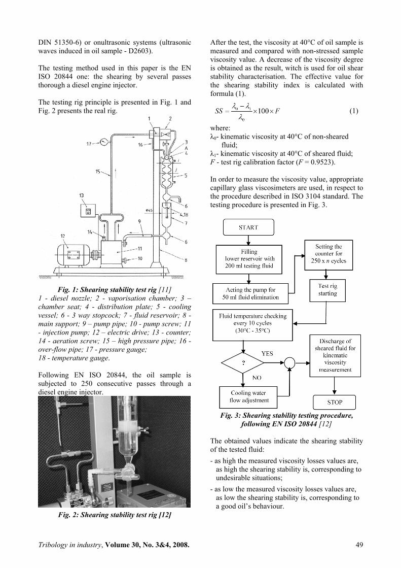
DIN 51350-6) or onultrasonic systems (ultrasonic waves induced in oil sample - D2603). The testing method used in this paper is the EN ISO 20844 one: the shearing by several passes thorough a diesel engine injector. The testing rig principle is presented in Fig. 1 and Fig. 2 presents the real rig.
Fig. 1: Shearing stability test rig [11]
1 - diesel nozzle; 2 - vaporisation chamber; 3 – chamber seat; 4 - distribution plate; 5 - cooling vessel; 6 - 3 way stopcock; 7 - fluid reservoir; 8 - main support; 9 – pump pipe; 10 - pump screw; 11 - injection pump; 12 – electric drive; 13 - counter; 14 - aeration screw; 15 – high pressure pipe; 16 - over-flow pipe; 17 - pressure gauge; 18 - temperature gauge. Following EN ISO 20844, the oil sample is subjected to 250 consecutive passes through a diesel engine injector.
Fig. 2: Shearing stability test rig [12]
After the test, the viscosity at 40°C of oil sample is measured and compared with non-stressed sample viscosity value. A decrease of the viscosity degree is obtained as the result, witch is used for oil shear stability characterisation. The effective value for the shearing stability index is calculated with formula (1).
(1)
where: λ0- kinematic viscosity at 40°C of non-sheared fluid; λ1- kinematic viscosity at 40°C of sheared fluid; F - test rig calibration factor (F = 0.9523). In order to measure the viscosity value, appropriate capillary glass viscosimeters are used, in respect to the procedure described in ISO 3104 standard. The testing procedure is presented in Fig. 3.
Fig. 3: Shearing stability testing procedure,
following EN ISO 20844 [12] The obtained values indicate the shearing stability of the tested fluid: - as high the measured viscosity losses values are,
as high the shearing stability is, corresponding to undesirable situations;
- as low the measured viscosity losses values are, as low the shearing stability is, corresponding to a good oil’s behaviour.

Tribology in industry, Volume 30, No. 3&4, 2008. 50
3. FOUR BALL TESTING METHOD Onto the four ball tribotester a sliding motion take place among a mobile ball and three fixed ones. Generally the loading of the ball system is obtained with a lever that has the middle point fixed. The parameters that could be measured are: the friction torque that acts on the fixed balls, generated by the movement of the mobile ball above them. The rotation speed is specified by standards that used this tribotester. The load could be constant or progressively applied, in a discontinuous or continuous way [13, 14], the load magnitude depending on the measuring purpose and method. The sliding motion between balls conducts to a shearing onto lubricant. The four ball machine is used to evaluating the antiwear and extreme pressure properties of lubricants. The procedures for the determination of these properties are described by some standards as: ASTM D2783, ASTM D4172, ISO 20623:2003, EN ISO 20623:2003 [15], STAS 8618_ 79 (Romanian standard), DIN 51350, JSA JIS K 2519, GOST 9490-75, IP 239. 3.1. APPARATUS - EN ISO 20623 The standards regulates procedures for the measurement of the extreme-pressure (EP) and anti-wear properties of lubricating oils and fluids by means of the four ball machine. The standard SR EN ISO 20623:2004 is the Romanian adoption by the endorsement method of the standard EN ISO 20623:2003 [15]. The components of mechanical design of the testing area as required by this standard are shown in Fig. 4 and the four ball tribotester is presented in Fig. 5. The load is applied through counter-weighted lever arm using a series of masses, specially designed. The test balls are lime polished, chrome alloyed steel balls of 12.000±0.0005 mm diameter, conforming the requirements of ISO 683-17:1999, type 1. It is recommended that the balls shall be specially supplied for the four ball testing device. For the measuring of the wear scar diameters on the fixed balls, the microscope is equipped with a calibrated measuring scale capable of measuring with an accuracy of ±0.01 mm. According to the type and optical axis of the microscope, the measurement of the scar diameters may be done
either removing or without removing the balls from the cup. For the control of the duration of the test is used an electronic timer, capable of reading to the nearest 0.2 s. Optionally, a friction recording device (consisting of a spring with one end anchored and with the other end attached, by a wire, to the calibrated arm on the cup assembly) could be used. The test conditions are: rotational speed: 1450÷1500 [rpm]; duration: 10 ±0.2 [s] or 60±0.5 [s]; load: 6…800 [kgf].
Fig. 4: Four ball machine - mechanical design of
the testing area 1 ball chuck holder; 2 ball chuck; 3 cam for removing ball chuck; 4 ball pot assembly; 5 ball pot mounting disc; 6 trust bearing; 7 cross head; 8 brass shims; 9 rubber disc; 10 step bearing; 11 counter-weighted lever arm; 12 fulcrum; 13 step bearing; 14 pressure pin. [15]
Fig. 5: The four ball machine [16]

Tribology in industry, Volume 30, No. 3&4, 2008. 51
3.2. GENERAL PROCEDURE - EN ISO 20623 According to the standard [15]:
- sampling in respect to the procedure described in ISO 3170;
- before testing, the machine must run unloaded for a minimum of 15 minutes;
- all necessary parts of the machine must be cleaned with appropriate solvent and dried; before each test, balls must be cleaned with an appropriate cleaning solvent and dried;
- the three fixed balls are putted into the cup and secured in position;
- the lubricant oil sample volume must be sufficient to cover the balls to a depth of at least 3 mm (8 ml to 10 ml);
- a clean ball must be fitted into the upper ball chuck;
- the load between balls are settled using appropriate masses;
- the timer is settled according to the lubricant and the purpose of the test;
- the main motor and the friction recorder, if required, are started.
After the testing time elapsed, for the measuring of the wear scar diameter, the balls are removed and washed again with cleaning solvent and dried. For a new test, all the above procedure must be repeated using four new balls and a fresh test lubricant. 4. EXPERIMENTAL RESULTS 4.1. TESTED OILS For experimental measurements where used two hydraulic oils, in two viscosity ranges (Tab. 1). These oils are recommended for high pressure hydraulic systems and for power transmission systems operating at high speeds and loads. Table 1: Tested oils specifications
Oil Viscosity at 40°C [cSt]
Viscosity at 100°C [cSt]
HLP-46 46.6 6.9 HLP-68 64.94 8.64
These working conditions are a powerful stress source for the polymeric additives in the oil, leading to long chains breaking and thus to the viscosity value decrease. 4.2. SHEARING STABILITY TESTS In order to establish shear stability parameter values for the selected oils, the kinematic viscosity at 40°C of several samples were measured. The same samples were subjected to accelerated shearing procedure, following the EN ISO 20844 requirements and the procedure presented in Fig. 3. Measuring the viscosity of stressed oil samples and using formula (1), the shearing stability was calculated (Tab. 2). Table 2: Shearing stability index
Oil Viscosity at 40°C
[cSt] Shearing stability
Initial Final HLP-46 47.4 39.2 15.1 HLP-68 66.2 56.8 13.5
In Tab. 2 one could observe that the HLP-68 oil provide a higher shearing stability, meaning that during life cycle the viscosity loss is less than in the HLP-46 oil case. It is obvious that during the life cycle the viscosity index of the oils is decreasing. As is specified in EN ISO 20844, there is no direct quantitative link between the shearing viscosity index and the behaviour of the oil in service but it can be a good indicator for the modification of the oil’s quality during time and thus, for maintenance planning . In order to use the shearing viscosity parameter value for predicting total service life of the oil, the evolution of the viscosity was represented in plot with viscosity index - number of passes axes. With this goal, several intermediate viscosity measurements were performed, at equal number of passes, before the last one at 250 passes, as the ISO 20844 requirements. Using dedicated software the acquired data was processed, obtaining as a result the viscosity variation plot for the tested oil, during the shearing test.

Tribology in industry, Volume 30, No. 3&4, 2008. 52
Assuming that the service conditions are constant during oil’s life cycle, viscosity measurements results obtained on the oil samples extracted from the working volume can be used for remaining oil’s life time prediction. In Fig. 6 - 7 are presented the plots obtained for HLP-46 and, respectively, HLP-68 oils.
Fig. 6: Viscosity variation for HLP-46 oil
Analysing Fig. 6 - 7 some particularities for the oils service behaviour could be praised. For both oils, a non-linear decrease of viscosity during the test is observed. The decrease is more rapid in the first period of the test, having a stabilized slope during the second part of the test. This can be explained by a specific shape of the polymeric chains that allow maintaining a minimum length even after shearing. The degradation rate is decreasing during the test period, the oil ensuring a minimum viscosity value.
Fig. 7: Viscosity variation for HLP-68 oil
From the shear stability point of view, the index presented in Tab. 2 is totally according with the experimental observations on the viscosity evolution, the values reflecting the capacity of oils to face the service requirements. The HLP-46 oil presents higher values for the shearing stability index, indicating a higher degradation rate. The HLP-68 oil presents lower values of shearing stability index, indicating a lower degradation rate.
The difference between degradation rates of the two oils could be explain by the higher content of polymeric additives in HLP-68 oil case. 4.3. FOUR BALL TESTS After a wear test, the three wear scars on the fixed balls are roughly circular. According to standard [15] for each wear scar two diameters are measured: one along the friction direction and the other perpendicularly on the first, six diameters corresponding to the three fixed balls. The average values of these is provided in the tables below. The experimental results obtained for the HLP 68 oil are shown in Tab.3 and Fig.8 Table 3: Experimental results for the HLP 68 oil
Loads [N] 160 240
Time [min.] 60 90 60 90 Average wear scar diameters
[mm] 0,290 0,332 0,358 0,362
Fig. 8 Wear scare diameters for the HLP 68 oil
The experimental results obtained for the HLP 46 oil is shown in Tab. 4 and Fig. 9. Table 4: Experimental results for the HLP 46 oil
Loads [N] 160 240
Time [min.] 60 90 60 90 Average wear scar diameters
[mm] 0,327 0,370 0,342 0,359

Tribology in industry, Volume 30, No. 3&4, 2008. 53
Fig. 9 Wear scar diameters for the HLP 46 oil
A comparison between the wear scar diameters for the two oils is done in Fig. 10 and 11.
Fig. 10 The comparison of the wear scare
diameters for 160 [N]
Fig. 11 The comparison of the wear scare
diameters for 240 [N] 5. DISCUTIONS AND CONCLUSIONS The paper presents the results of a comparative study developed on two hydraulic oils regarding the influence of the shearing on their functioning performances. As test method, the EN ISO 20844 and EN ISO 20623 are used.
The results of shearing tests show that the shear stability, as oil's characteristic, can be linked to the behaviour in the working conditions of the lubricants. The shear stability index value can be use to optimize the oils selection, taking into account different requirements regarding oil's performance and service lifetime. The four ball tests show that the increasing of the testing time leads to the growing of wear scar diameters, for both tested oils. For the same oil and the same test time, the increase of the contact load has a small influence on wear scar diameter (4 - 12%, Fig. 10 and Fig. 11). The small difference between the values of the forces could be an explanation. The influence of the two oils characteristics on wear scar diameter can not be determined, the results being contradictory. A possible cause can be the small differences between them. As general conclusion it could be noticed that:
1. The shearing phenomenon (caused by long chain molecules of additives braking) is occuring in both tests;
2. Results of subjecting the oils to the both tests condition show the same kind of oils’ degradation in time. This observation leads to the idea that these tests can be used (one, other or both) for characterisation of oils’ behaviour during service life-time;
3. Based on different amount of time and hand-work needed by the presented tests and that the shearing stability test don’t give some direct indications about the oil’s characteristics in service, one could conclude that the four ball test is more efficient.
ACKNOWLEDGMENTS This research was supported by National Authority for Scientific Research (ANCS), Ministry of Education and Research, Romania, under Grant CEEX M4 - C2 – 452 "Adoption and Implementation of Test Methods for Lubricants Conformity Assessments - CELUBE".

Tribology in industry, Volume 30, No. 3&4, 2008. 54
REFERENCES
[1] Abdel-Azim, A. et al., "Polymeric Additives for Improving the Flow Properties and Viscosity Index of Lubricating Oils", J. of Polymer Research, 8 (2001), 2, 111-118.
[2] Yavuz Yorulmaz, "Alkylated Polymers as Lube Oil Additives", J. of Mat. Science, 18 (1983), 6, 1638- 1634.
[3] Boerlage, G.D., Four-Ball Testing Apparatus for Extreme Pressure Lubricants. Engineering, Vol 1. CXXXVI, No. 3522 (1933) 46.
[4] Jayadasa, N.H. et al., “Tribological evaluation of coconut oil as angle environment-friendly lubricant”, Trib. Int., 40 (2007) 350–354.
[5] Rastogi, R.B. et al., “Application of molybdenum complexes of 1-aryl-2,5-dithiohydrazodicarbonamides as extreme pressure lubricant additives”, Wear 252 (2002) 686–692.
[6] Huang, W. et al., “Tribological performance and action mechanism of S-[2-(acetamido) thiazol-1-yl] dialkyl dithiocarbamate as additive in rapeseed oil”, Wear 256 (2004) 1106–1113.
[7] Xiangqiong, Z. et al., “Tribological study of trioctylthiotriazine derivative as lubricating oil additive”, Wear 258 (2005) 800–805.
[8] Jiang, G. et al., “A study on fullerene–acrylamide copolymer nanoball—a new type of water-based lubrication additive”, Wear 258 (2005) 1625–1629.
[9] Huang, H.D. et al., “An investigation on tribological properties of graphite nanosheets as oil additive”, Wear 261 (2006) 140–144.
[10] Hernandez Battez, A. et al, “The tribological behaviour of ZnO nanoparticles as an additive to PAO6”, Wear 261 (2006) 256–263.
[11] EN ISO 20844:2004 Petroleum and related products - Determination of the shear stability of polymer- containing oils using a diesel injector nozzle.
[12] Ciortan, S., Rîpă, M., Chiculiţă, S., “Influence of shear stability on oils behaviour”, ROTRIB’07 - The 10-th Intern. Conf. on Tribology, Bucharest, Romania, 2007, paper RO-086 on CD.
[13] Troyer, D.D., “The Sequential Four Ball Test”, Practicing Oil Analysis Magazine. November (1999), online http://www.practicingoilanalysis.com/ article_detail.asp?articleid=35&related bookgroup=OilAnalysis (2.03.2007).
[14] Perez, J. et al., “Sequential Four-Ball Study of Some Lubricating Oils”, Lubric. Eng. Sept. (1999) 28-30.
[15] EN ISO 20623:2003 Petroleum and related products - Determination of the extreme-pressure and anti-wear properties of fluids — Four ball method (European conditions) (20623:2003).
[16] Spânu, C., Rîpă, M., Ştefănescu, I., “Comparative study of the testing methods using four ball machine”, Intern. Conf. “ECOTRIB 2007”, June 12–15, 2007, Ljubljana, Slovenia, .