characteristics pendant control stations double insulated ... · 3 pendant control stations 6...
TRANSCRIPT
2
Pendant control stations 6 Double insulated, type XAC AFor control circuits
Characteristics 6
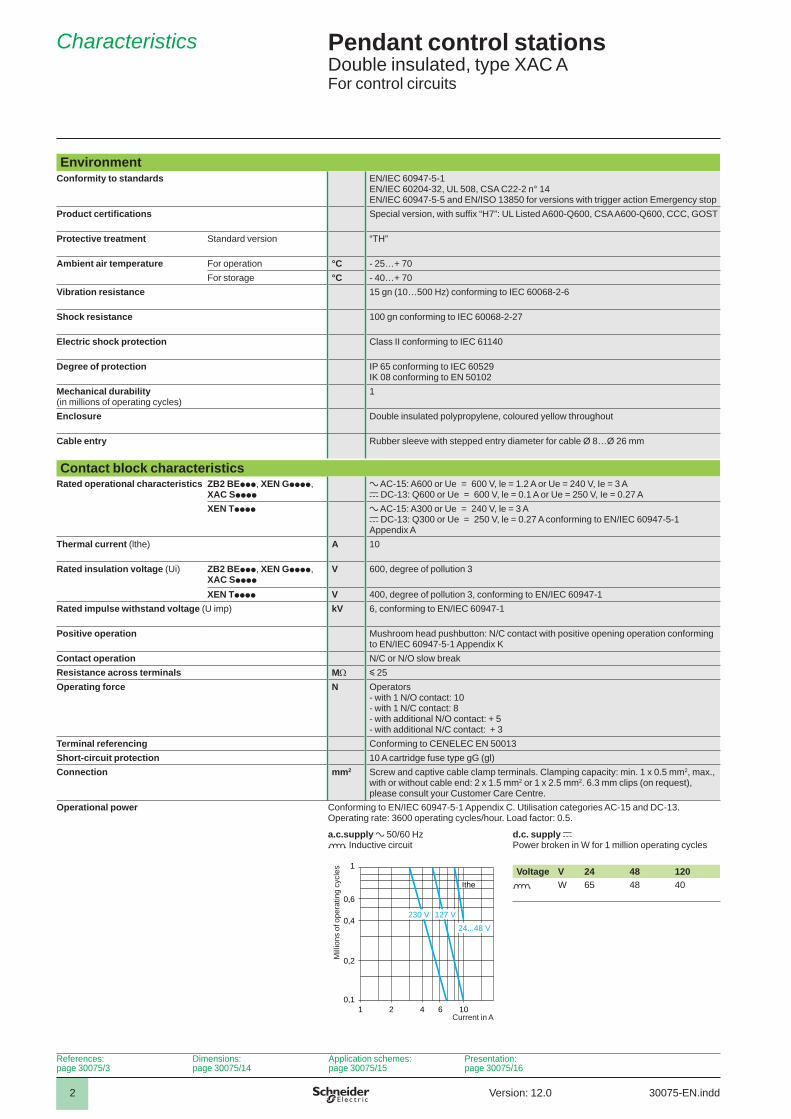
EnvironmentConformity to standards EN/IEC 60947-5-1
EN/IEC 60204-32, UL 508, CSA C22-2 n° 14EN/IEC 60947-5-5 and EN/ISO 13850 for versions with trigger action Emergency stop
Product certifi cations Special version, with suffi x “H7”: UL Listed A600-Q600, CSA A600-Q600, CCC, GOST
Protective treatment Standard version “TH”
Ambient air temperature For operation °C - 25…+ 70For storage °C - 40…+ 70
Vibration resistance 15 gn (10…500 Hz) conforming to IEC 60068-2-6
Shock resistance 100 gn conforming to IEC 60068-2-27
Electric shock protection Class II conforming to IEC 61140
Degree of protection IP 65 conforming to IEC 60529IK 08 conforming to EN 50102
Mechanical durability(in millions of operating cycles)
1
Enclosure Double insulated polypropylene, coloured yellow throughout
Cable entry Rubber sleeve with stepped entry diameter for cable Ø 8…Ø 26 mm
Contact block characteristicsRated operational characteristics ZB2 BEppp, XEN Gpppp,
XAC Spppp a AC-15: A600 or Ue = 600 V, le = 1.2 A or Ue = 240 V, Ie = 3 Ac DC-13: Q600 or Ue = 600 V, le = 0.1 A or Ue = 250 V, Ie = 0.27 A
XEN Tpppp a AC-15: A300 or Ue = 240 V, le = 3 Ac DC-13: Q300 or Ue = 250 V, le = 0.27 A conforming to EN/IEC 60947-5-1 Appendix A
Thermal current (lthe) A 10
Rated insulation voltage (Ui) ZB2 BEppp, XEN Gpppp, XAC Spppp
V 600, degree of pollution 3
XEN Tpppp V 400, degree of pollution 3, conforming to EN/IEC 60947-1Rated impulse withstand voltage (U imp) kV 6, conforming to EN/IEC 60947-1
Positive operation Mushroom head pushbutton: N/C contact with positive opening operation conforming to EN/IEC 60947-5-1 Appendix K
Contact operation N/C or N/O slow breakResistance across terminals M y 25Operating force N Operators
- with 1 N/O contact: 10- with 1 N/C contact: 8- with additional N/O contact: + 5- with additional N/C contact: + 3
Terminal referencing Conforming to CENELEC EN 50013Short-circuit protection 10 A cartridge fuse type gG (gl)Connection mm2 Screw and captive cable clamp terminals. Clamping capacity: min. 1 x 0.5 mm2, max.,
with or without cable end: 2 x 1.5 mm2 or 1 x 2.5 mm2. 6.3 mm clips (on request), please consult your Customer Care Centre.
Operational power Conforming to EN/IEC 60947-5-1 Appendix C. Utilisation categories AC-15 and DC-13.Operating rate: 3600 operating cycles/hour. Load factor: 0.5.
a.c.supply a 50/60 Hzo Inductive circuit
d.c. supply c Power broken in W for 1 million operating cycles
Voltage V 24 48 120o W 65 48 40
1 2 4 6 100,1
0,2
0,4
0,6
1
230 V 127 V
24...48 V
Ithe
Mill
ions
of o
pera
ting
cycl
es
Current in A
References:page 30075/3
Dimensions:page 30075/14
Application schemes:page 30075/15
Presentation:page 30075/16
30075-EN.inddVersion: 12.0

3
Pendant control stations 6 Double insulated, type XAC AFor control circuitsComplete stations “ready for use”
References 6
For control of single-speed motorsFunctions Number of
operatorsContact block(s) and scheme Reference Weight
kgPer direction For Emergency stop2 mechanically interlocked
1 N/OZB2 BE101
– XAC A271 0.475
1 N/C + 1 N/OZB2 BE102+ZB2 BE101
– XAC A281 0.500
2 mechanically interlocked+ 1 trigger action latching Emergency stop Ø 30 mm operator ZA2 BS834 (1)
1 N/OZB2 BE101
1 N/CZB2 BE102
XAC A2714 (1) 0.575
1 N/C + 1 N/OZB2 BE102+ZB2 BE101
1 N/CZB2 BE102
XAC A2814 (1) 0.600
1 N/OZB2 BE101
1 N/C + N/C+ N/C XEN T1192
XAC A27141 (1) 0.615
1 N/C + 1 N/OZB2 BE102+ZB2 BE101
1 N/C + N/C+ N/C XEN T1192
XAC A28141 (1) 0.635
(1) Trigger action mechanically latching Emergency stop pushbuttons conform to standards EN/IEC 60204-32, EN/ISO 13850, Machinery directive 98/37/EC and standard EN/IEC 60947-5-5.
1112
2122
3132
1314
1112
XAC A27141XAC A28141
DF5
6552
4
1112
2122
3132
1314
1112
1314
1112XAC A2714
XAC A2814
DF5
6552
4
1112
1314
1314
1112XAC A271
XAC A281
DF5
6552
3
1314
30075-EN.indd Version: 12.0
44
Pendant control stations 6 Double insulated, type XAC AFor control circuitsComplete stations “ready for use”
References (continued) 6
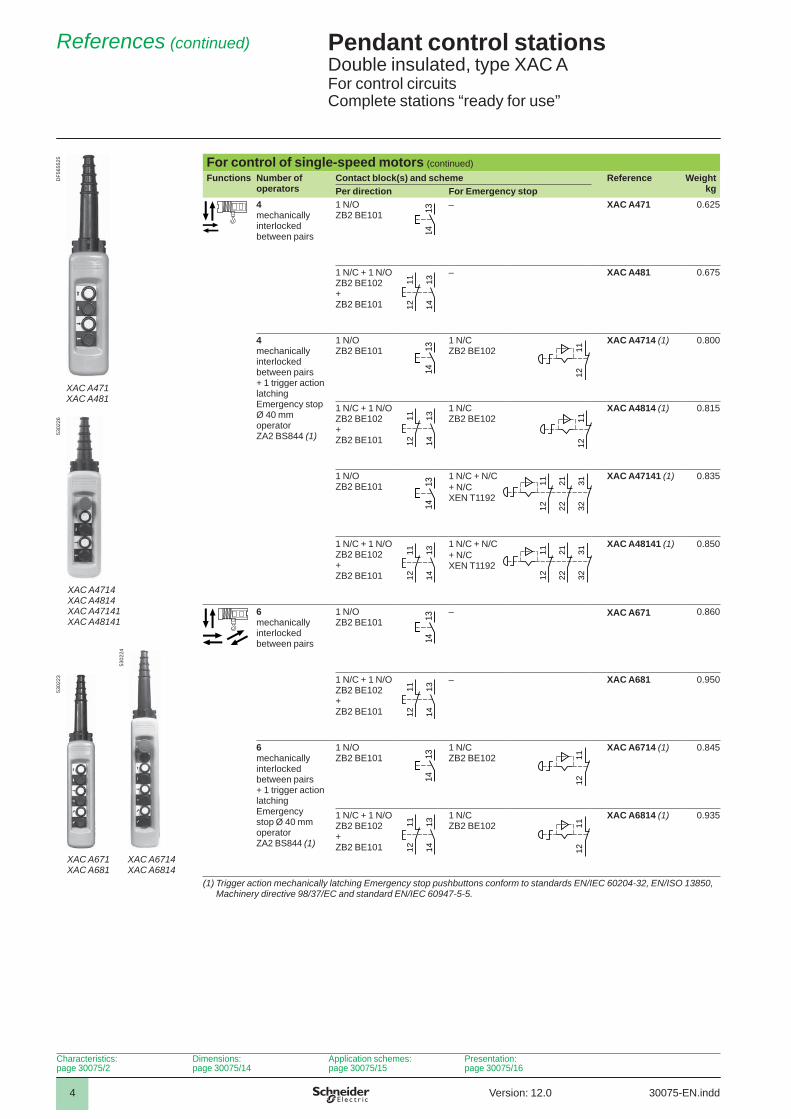
For control of single-speed motors (continued)Functions Number of
operatorsContact block(s) and scheme Reference Weight
kgPer direction For Emergency stop4 mechanically interlocked between pairs
1 N/OZB2 BE101
– XAC A471 0.625
1 N/C + 1 N/OZB2 BE102+ZB2 BE101
– XAC A481 0.675
4 mechanically interlocked between pairs + 1 trigger action latching Emergency stop Ø 40 mm operator ZA2 BS844 (1)
1 N/O ZB2 BE101
1 N/CZB2 BE102
XAC A4714 (1) 0.800
1 N/C + 1 N/OZB2 BE102+ZB2 BE101
1 N/CZB2 BE102
XAC A4814 (1) 0.815
1 N/O ZB2 BE101
1 N/C + N/C+ N/C XEN T1192
XAC A47141 (1) 0.835
1 N/C + 1 N/O ZB2 BE102+ ZB2 BE101
1 N/C + N/C+ N/C XEN T1192
XAC A48141 (1) 0.850
6mechanically interlocked between pairs
1 N/O ZB2 BE101
– XAC A671 0.860
1 N/C + 1 N/O ZB2 BE102+ ZB2 BE101
– XAC A681 0.950
6 mechanically interlocked between pairs+ 1 trigger action latching Emergency stop Ø 40 mm operator ZA2 BS844 (1)
1 N/O ZB2 BE101
1 N/CZB2 BE102
XAC A6714 (1) 0.845
1 N/C + 1 N/OZB2 BE102+ZB2 BE101
1 N/CZB2 BE102
XAC A6814 (1) 0.935
(1) Trigger action mechanically latching Emergency stop pushbuttons conform to standards EN/IEC 60204-32, EN/ISO 13850, Machinery directive 98/37/EC and standard EN/IEC 60947-5-5.
1112
1314
1112
1112
1314
1314
1112
XAC A671XAC A681
5302
23
XAC A6714XAC A6814
5302
24
1314
1112
2122
3132
1314
1112
1112
2122
3132
1314
1112
1314
1112
XAC A4714XAC A4814XAC A47141XAC A48141
5302
26
1112
1314
1314
1112
XAC A471XAC A481
DF5
6552
5
1314
Characteristics:page 30075/2
Dimensions:page 30075/14
Application schemes:page 30075/15
Presentation:page 30075/16
30075-EN.inddVersion: 12.0
55
Pendant control stations 6 Double insulated, type XAC AFor control circuitsComplete stations “ready for use”
References (continued) 6
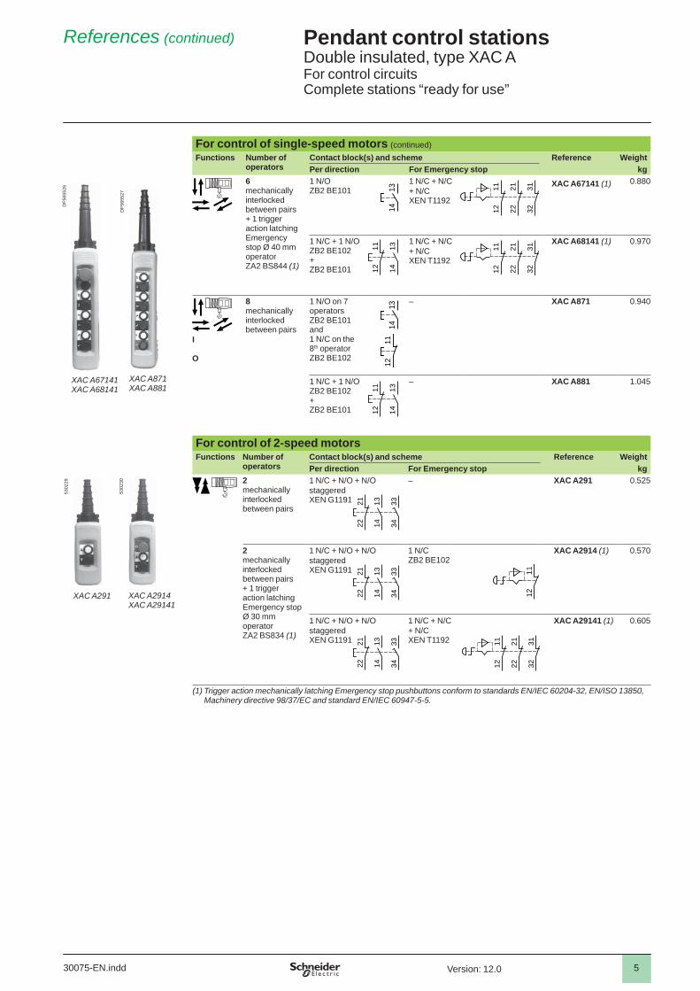
For control of single-speed motors (continued)Functions Number of
operatorsContact block(s) and scheme Reference WeightPer direction For Emergency stop kg
6 mechanically interlocked between pairs+ 1 trigger action latching Emergency stop Ø 40 mm operator ZA2 BS844 (1)
1 N/OZB2 BE101
1 N/C + N/C+ N/C XEN T1192
XAC A67141 (1) 0.880
1 N/C + 1 N/OZB2 BE102+ZB2 BE101
1 N/C + N/C+ N/C XEN T1192
XAC A68141 (1) 0.970
I
O
8mechanically interlocked between pairs
1 N/O on 7 operators ZB2 BE101 and1 N/C on the 8th operator ZB2 BE102
– XAC A871 0.940
1 N/C + 1 N/OZB2 BE102+ZB2 BE101
– XAC A881 1.045
For control of 2-speed motors Functions Number of
operatorsContact block(s) and scheme Reference WeightPer direction For Emergency stop kg
2mechanically interlocked between pairs
1 N/C + N/O + N/Ostaggered XEN G1191
– XAC A291 0.525
2 mechanically interlocked between pairs + 1 trigger action latching Emergency stop Ø 30 mm operator ZA2 BS834 (1)
1 N/C + N/O + N/Ostaggered XEN G1191
1 N/CZB2 BE102
XAC A2914 (1) 0.570
1 N/C + N/O + N/Ostaggered XEN G1191
1 N/C + N/C+ N/C XEN T1192
XAC A29141 (1) 0.605
(1) Trigger action mechanically latching Emergency stop pushbuttons conform to standards EN/IEC 60204-32, EN/ISO 13850, Machinery directive 98/37/EC and standard EN/IEC 60947-5-5.
1112
2122
3132
1314
2 122
3334
XAC A2914XAC A29141
5302
30
1112
1314
2 122
3334XAC A291
5302
29
1314
2 122
3334
1314
1112
XAC A871XAC A881
DF5
6552
7
1314
1112
1112
2122
3132
1314
1112
XAC A67141XAC A68141
DF5
6552
6 1112
2122
3132
1314
30075-EN.indd Version: 12.0
6
Pendant control stations 6 Double insulated, type XAC AFor control circuitsComplete stations “ready for use”
References (continued) 6
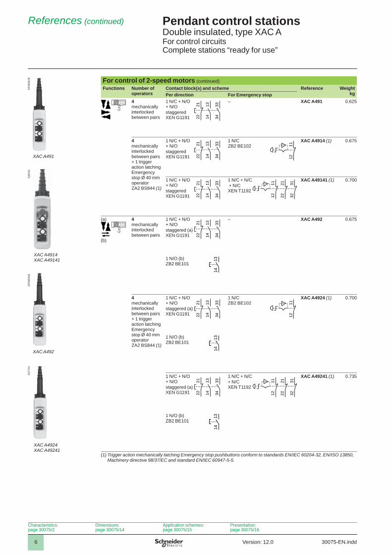
For control of 2-speed motors (continued)Functions Number of
operatorsContact block(s) and scheme Reference Weight
kgPer direction For Emergency stop4mechanically interlocked between pairs
1 N/C + N/O+ N/Ostaggered XEN G1191
– XAC A491 0.625
4 mechanically interlocked between pairs+ 1 trigger action latching Emergency stop Ø 40 mm operator ZA2 BS844 (1)
1 N/C + N/O + N/Ostaggered XEN G1191
1 N/CZB2 BE102
XAC A4914 (1) 0.675
1 N/C + N/O + N/Ostaggered XEN G1191
1 N/C + N/C + N/C XEN T1192
XAC A49141 (1) 0.700
(a)
(b)
4mechanically interlocked between pairs
1 N/C + N/O + N/Ostaggered (a) XEN G1191
– XAC A492 0.675
1 N/O (b)ZB2 BE101
4 mechanically interlocked between pairs + 1 trigger action latching Emergency stop Ø 40 mm operator ZA2 BS844 (1)
1 N/C + N/O + N/Ostaggered (a) XEN G1191
1 N/CZB2 BE102
XAC A4924 (1) 0.700
1 N/O (b)ZB2 BE101
1 N/C + N/O + N/Ostaggered (a) XEN G1191
1 N/C + N/C+ N/C XEN T1192
XAC A49241 (1) 0.735
1 N/O (b)ZB2 BE101
(1) Trigger action mechanically latching Emergency stop pushbuttons conform to standards EN/IEC 60204-32, EN/ISO 13850, Machinery directive 98/37/EC and standard EN/IEC 60947-5-5.
1314
1112
2122
3132
1314
2 122
3334
1314
XAC A4924XAC A49241
5377
43
1112
1314
2 122
3334
1314
XAC A492
DF5
6552
8
1314
2 122
3334
1112
2122
3132
1314
2 122
3334
XAC A4914XAC A49141
5302
31
1112
1314
2 122
3334XAC A491
DF5
6552
8
1314
2 122
3334
Characteristics:page 30075/2
Dimensions:page 30075/14
Application schemes:page 30075/15
Presentation:page 30075/16
30075-EN.inddVersion: 12.0
7
Pendant control stations 6 Double insulated, type XAC AFor control circuitsEmpty enclosures
References 6
Empty enclosuresDescription Number of
cut-outsReference Weight
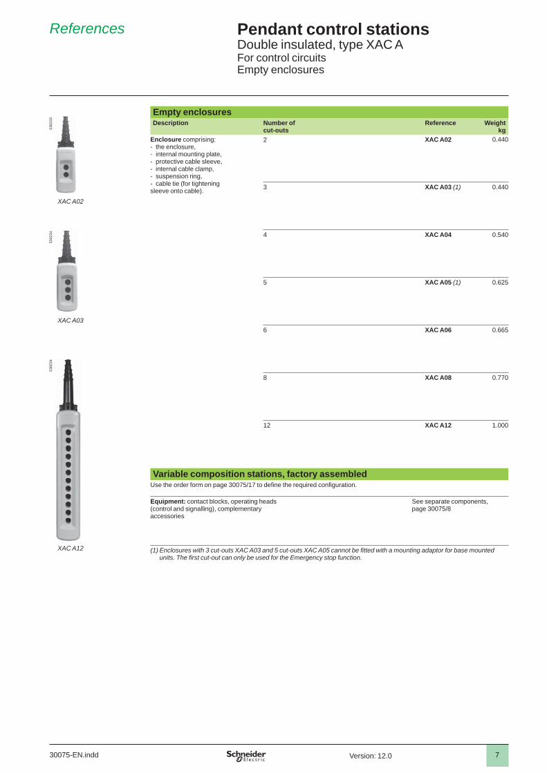
kgEnclosure comprising:- the enclosure, - internal mounting plate, - protective cable sleeve, - internal cable clamp, - suspension ring, - cable tie (for tightening sleeve onto cable).
2 XAC A02 0.440
3 XAC A03 (1) 0.440
4 XAC A04 0.540
5 XAC A05 (1) 0.625
6 XAC A06 0.665
8 XAC A08 0.770
12 XAC A12 1.000
Variable composition stations, factory assembledUse the order form on page 30075/17 to defi ne the required confi guration.
Equipment: contact blocks, operating heads (control and signalling), complementary accessories
See separate components,page 30075/8
(1) Enclosures with 3 cut-outs XAC A03 and 5 cut-outs XAC A05 cannot be fi tted with a mounting adaptor for base mounted units. The fi rst cut-out can only be used for the Emergency stop function.
XAC A12
5302
34
XAC A03
5302
34
XAC A02
5302
33
30075-EN.indd Version: 12.0
8
Pendant control stations 6 Double insulated, type XAC AFor control circuitsSeparate components and spare parts
References 6
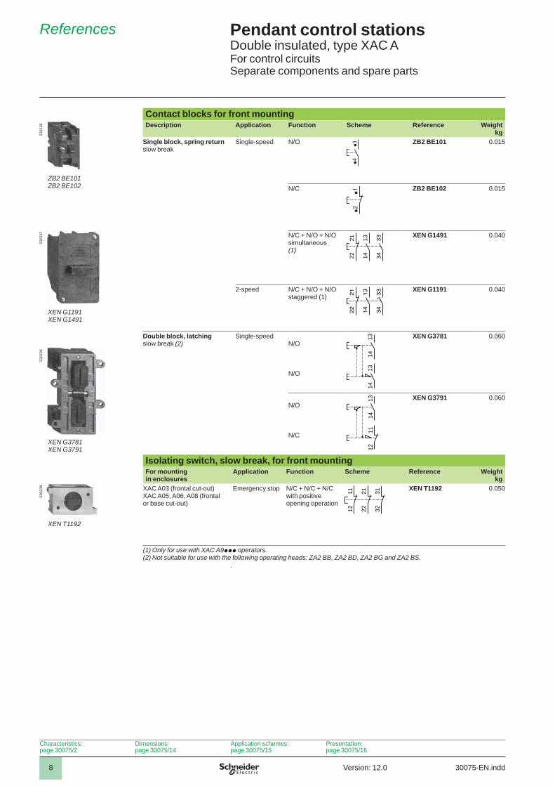
Contact blocks for front mountingDescription Application Function Scheme Reference Weight
kgSingle block, spring return slow break
Single-speed N/O p3
p4
ZB2 BE101 0.015
N/C ZB2 BE102 0.015
N/C + N/O + N/O simultaneous (1)
XEN G1491 0.040
2-speed N/C + N/O + N/O staggered (1)
XEN G1191 0.040
Double block, latching slow break (2)
Single-speedN/O
N/O
XEN G3781 0.060
N/O
N/C
XEN G3791 0.060
Isolating switch, slow break, for front mountingFor mounting in enclosures
Application Function Scheme Reference Weightkg
XAC A03 (frontal cut-out)XAC A05, A06, A08 (frontal or base cut-out)
Emergency stop N/C + N/C + N/C with positive opening operation
XEN T1192 0.050
(1) Only for use with XAC A9ppp operators.(2) Not suitable for use with the following operating heads: ZA2 BB, ZA2 BD, ZA2 BG and ZA2 BS.
.
XEN T1192
5302
39
1112
2122
3132
1314
1112
XEN G3781XEN G3791
5302
36
1314
1314
XEN G1191XEN G1491
5302
37
13
14
33
34
21
22
13
14
33
34
21
22
p2p1
ZB2 BE101ZB2 BE102
5302
38
Characteristics:page 30075/2
Dimensions:page 30075/14
Application schemes:page 30075/15
Presentation:page 30075/16
30075-EN.inddVersion: 12.0
9
Pendant control stations 6 Double insulated, type XAC AFor control circuitsSeparate components and spare parts
References (continued) 6
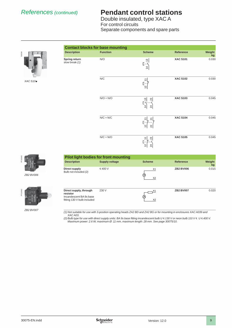
Contact blocks for base mountingDescription Function Scheme Reference Weight
kgSpring returnslow break (1)
N/O XAC S101 0.030
N/C XAC S102 0.030
N/O + N/O XAC S103 0.045
N/C + N/C XAC S104 0.045
N/C + N/O XAC S105 0.045
Pilot light bodies for front mountingDescription Supply voltage Scheme Reference Weight
kgDirect supplyBulb not included (2)
y 400 V ZB2 BV006 0.015
Direct supply, through resistorIncandescent BA 9s base fi tting 130 V bulb included
230 V ZB2 BV007 0.020
(1) Not suitable for use with 3-position operating heads ZA2 BD and ZA2 BG or for mounting in enclosures XAC A039 and XAC A03.
(2) Bulb type for use with direct supply units: BA 9s base fi tting incandescent bulb U y 130 V or neon bulb 110 V y U y 400 V. Maximum power: 2.6 W, maximum Ø: 11 mm, maximum length: 28 mm. See page 30075/10 .
ZB2 BV007
PF1
1046
2
X1
X2
ZB2 BV006
PF1
1046
1
X1
X2
1112
2324
1112
2122
2324
1314
1112
XAC S10p
5302
40
1314
30075-EN.indd Version: 12.0
10
Pendant control stations 6 Double insulated, type XAC AFor control circuitsSeparate components and spare parts
References (continued) 6
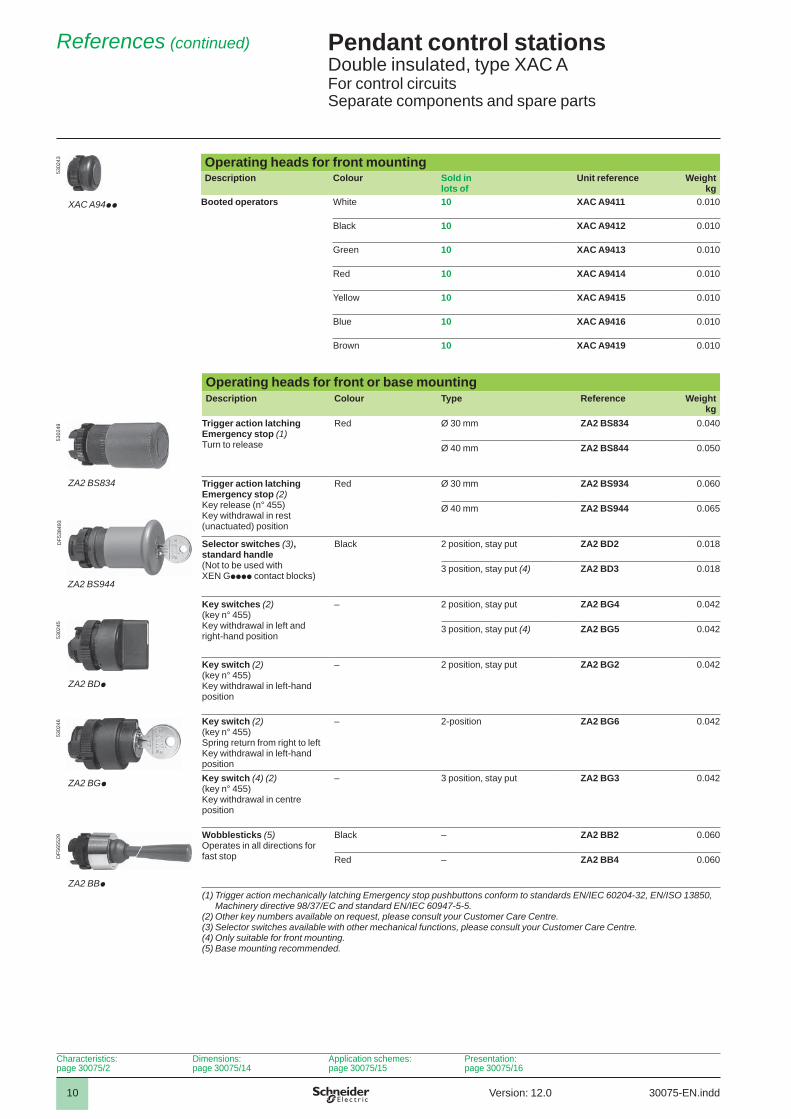
Operating heads for front mountingDescription Colour Sold in
lots ofUnit reference Weight
kgBooted operators White 10 XAC A9411 0.010
Black 10 XAC A9412 0.010
Green 10 XAC A9413 0.010
Red 10 XAC A9414 0.010
Yellow 10 XAC A9415 0.010
Blue 10 XAC A9416 0.010
Brown 10 XAC A9419 0.010
Operating heads for front or base mountingDescription Colour Type Reference Weight
kgTrigger action latching Emergency stop (1) Turn to release
Red Ø 30 mm ZA2 BS834 0.040
Ø 40 mm ZA2 BS844 0.050
Trigger action latching Emergency stop (2)Key release (n° 455) Key withdrawal in rest (unactuated) position
Red Ø 30 mm ZA2 BS934 0.060
Ø 40 mm ZA2 BS944 0.065
Selector switches (3), standard handle(Not to be used with XEN Gpppp contact blocks)
Black 2 position, stay put ZA2 BD2 0.018
3 position, stay put (4) ZA2 BD3 0.018
Key switches (2)(key n° 455)Key withdrawal in left and right-hand position
– 2 position, stay put ZA2 BG4 0.042
3 position, stay put (4) ZA2 BG5 0.042
Key switch (2)(key n° 455)Key withdrawal in left-hand position
– 2 position, stay put ZA2 BG2 0.042
Key switch (2)(key n° 455)Spring return from right to leftKey withdrawal in left-hand position
– 2-position ZA2 BG6 0.042
Key switch (4) (2)(key n° 455)Key withdrawal in centre position
– 3 position, stay put ZA2 BG3 0.042
Wobblesticks (5) Operates in all directions for fast stop
Black – ZA2 BB2 0.060
Red – ZA2 BB4 0.060
(1) Trigger action mechanically latching Emergency stop pushbuttons conform to standards EN/IEC 60204-32, EN/ISO 13850, Machinery directive 98/37/EC and standard EN/IEC 60947-5-5.
(2) Other key numbers available on request, please consult your Customer Care Centre.(3) Selector switches available with other mechanical functions, please consult your Customer Care Centre.(4) Only suitable for front mounting.(5) Base mounting recommended.
ZA2 BBp
DF5
6552
9
ZA2 BGp
5302
46
ZA2 BDp
5302
45
ZA2 BS944
DF5
3849
3
ZA2 BS834
5302
49
XAC A94pp
5302
43
Characteristics:page 30075/2
Dimensions:page 30075/14
Application schemes:page 30075/15
Presentation:page 30075/16
30075-EN.inddVersion: 12.0
11
Pendant control stations 6 Double insulated, type XAC AFor control circuitsSeparate components and spare parts
References (continued) 6
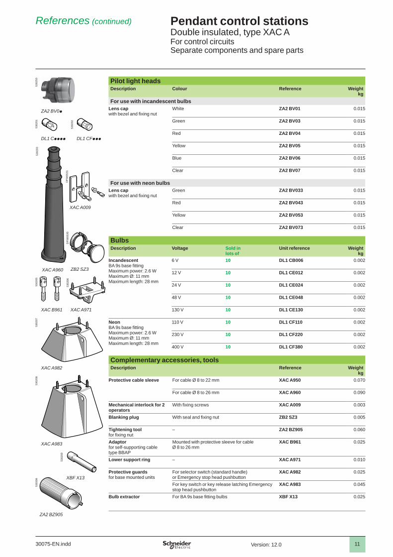
Pilot light headsDescription Colour Reference Weight
kgFor use with incandescent bulbs
Lens cap with bezel and fi xing nut
White ZA2 BV01 0.015
Green ZA2 BV03 0.015
Red ZA2 BV04 0.015
Yellow ZA2 BV05 0.015
Blue ZA2 BV06 0.015
Clear ZA2 BV07 0.015
For use with neon bulbsLens cap with bezel and fi xing nut
Green ZA2 BV033 0.015
Red ZA2 BV043 0.015
Yellow ZA2 BV053 0.015
Clear ZA2 BV073 0.015
Bulbs Description Voltage Sold in
lots ofUnit reference Weight
kgIncandescentBA 9s base fi ttingMaximum power: 2.6 WMaximum Ø: 11 mmMaximum length: 28 mm
6 V 10 DL1 CB006 0.002
12 V 10 DL1 CE012 0.002
24 V 10 DL1 CE024 0.002
48 V 10 DL1 CE048 0.002
130 V 10 DL1 CE130 0.002
NeonBA 9s base fi ttingMaximum power: 2.6 WMaximum Ø: 11 mmMaximum length: 28 mm
110 V 10 DL1 CF110 0.002
230 V 10 DL1 CF220 0.002
400 V 10 DL1 CF380 0.002
Complementary accessories, toolsDescription Reference Weight
kgProtective cable sleeve For cable Ø 8 to 22 mm XAC A950 0.070
For cable Ø 8 to 26 mm XAC A960 0.090
Mechanical interlock for 2 operators
With fi xing screws XAC A009 0.003
Blanking plug With seal and fi xing nut ZB2 SZ3 0.005
Tightening tool for fi xing nut
– ZA2 BZ905 0.060
Adaptor for self-supporting cabletype BBAP
Mounted with protective sleeve for cable Ø 8 to 26 mm
XAC B961 0.025
Lower support ring – XAC A971 0.010
Protective guards for base mounted units
For selector switch (standard handle)or Emergency stop head pushbutton
XAC A982 0.025
For key switch or key release latching Emergency stop head pushbutton
XAC A983 0.045
Bulb extractor For BA 9s base fi tting bulbs XBF X13 0.025
XBF X13
5302
00
XAC A983
5302
08
XAC A982
5302
07
XAC B961
5302
05
XAC A971
5302
06
5303
06
ZA2 BZ905
XAC A960
5302
03
XAC A009
ZB2 SZ3
DF5
6553
1D
F565
530
DL1 Cpppp
5302
01
DL1 CFppp
5302
02
ZA2 BV0p
5302
50
30075-EN.indd Version: 12.0
12
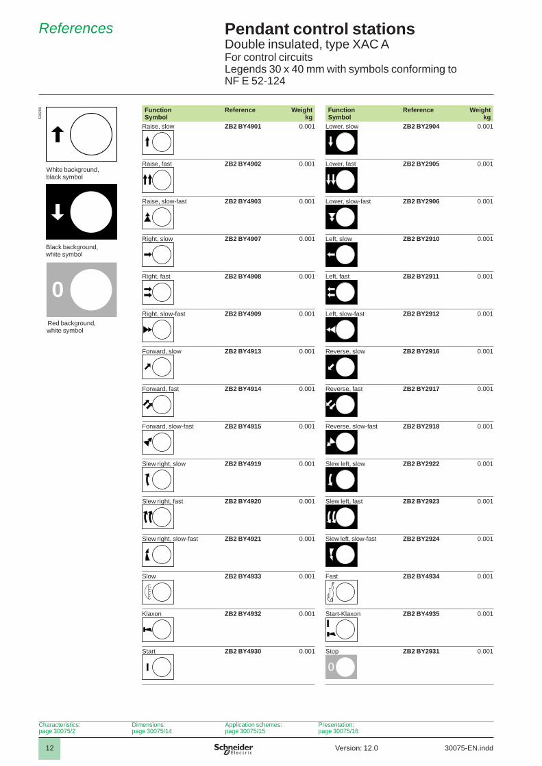
Pendant control stations 6 Double insulated, type XAC AFor control circuitsLegends 30 x 40 mm with symbols conforming toNF E 52-124
References 6
Function Symbol
Reference Weightkg
Function Symbol
Reference Weightkg
Raise, slow ZB2 BY4901 0.001 Lower, slow ZB2 BY2904 0.001
Raise, fast ZB2 BY4902 0.001 Lower, fast ZB2 BY2905 0.001
Raise, slow-fast ZB2 BY4903 0.001 Lower, slow-fast ZB2 BY2906 0.001
Right, slow ZB2 BY4907 0.001 Left, slow ZB2 BY2910 0.001
Right, fast ZB2 BY4908 0.001 Left, fast ZB2 BY2911 0.001
Right, slow-fast ZB2 BY4909 0.001 Left, slow-fast ZB2 BY2912 0.001
Forward, slow ZB2 BY4913 0.001 Reverse, slow ZB2 BY2916 0.001
Forward, fast ZB2 BY4914 0.001 Reverse, fast ZB2 BY2917 0.001
Forward, slow-fast ZB2 BY4915 0.001 Reverse, slow-fast ZB2 BY2918 0.001
Slew right, slow ZB2 BY4919 0.001 Slew left, slow ZB2 BY2922 0.001
Slew right, fast ZB2 BY4920 0.001 Slew left, fast ZB2 BY2923 0.001
Slew right, slow-fast ZB2 BY4921 0.001 Slew left, slow-fast ZB2 BY2924 0.001
Slow ZB2 BY4933 0.001 Fast ZB2 BY4934 0.001
Klaxon ZB2 BY4932 0.001 Start-Klaxon ZB2 BY4935 0.001
Start ZB2 BY4930 0.001 Stop ZB2 BY2931 0.001
0
0
White background, black symbol
5302
09
Black background, white symbol
Red background, white symbol
Characteristics:page 30075/2
Dimensions:page 30075/14
Application schemes:page 30075/15
Presentation:page 30075/16
30075-EN.inddVersion: 12.0
13
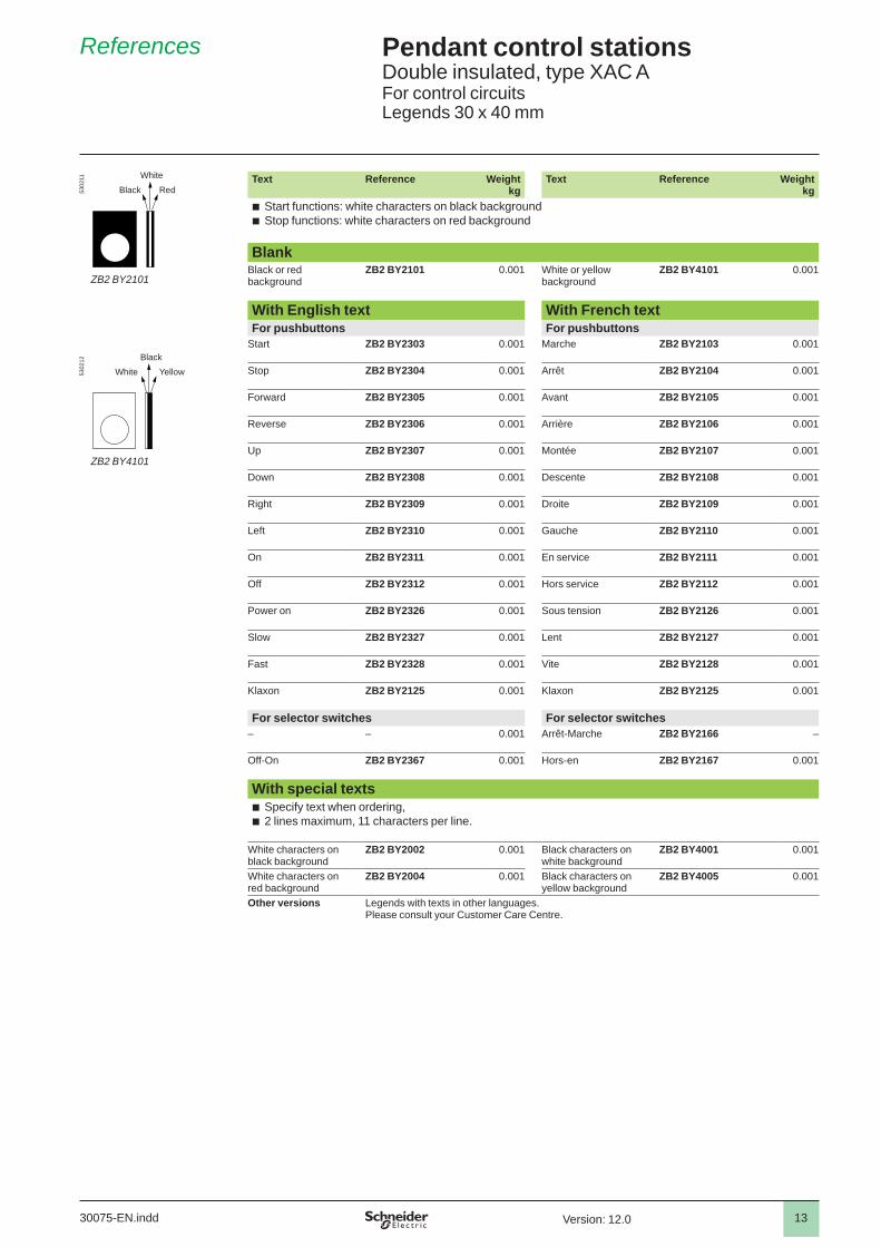
Pendant control stations 6 Double insulated, type XAC AFor control circuitsLegends 30 x 40 mm
References 6
Text Reference Weightkg
Text Reference Weightkg
b Start functions: white characters on black background b Stop functions: white characters on red background
BlankBlack or red background
ZB2 BY2101 0.001 White or yellow background
ZB2 BY4101 0.001
With English text With French textFor pushbuttons For pushbuttons
Start ZB2 BY2303 0.001 Marche ZB2 BY2103 0.001
Stop ZB2 BY2304 0.001 Arrêt ZB2 BY2104 0.001
Forward ZB2 BY2305 0.001 Avant ZB2 BY2105 0.001
Reverse ZB2 BY2306 0.001 Arrière ZB2 BY2106 0.001
Up ZB2 BY2307 0.001 Montée ZB2 BY2107 0.001
Down ZB2 BY2308 0.001 Descente ZB2 BY2108 0.001
Right ZB2 BY2309 0.001 Droite ZB2 BY2109 0.001
Left ZB2 BY2310 0.001 Gauche ZB2 BY2110 0.001
On ZB2 BY2311 0.001 En service ZB2 BY2111 0.001
Off ZB2 BY2312 0.001 Hors service ZB2 BY2112 0.001
Power on ZB2 BY2326 0.001 Sous tension ZB2 BY2126 0.001
Slow ZB2 BY2327 0.001 Lent ZB2 BY2127 0.001
Fast ZB2 BY2328 0.001 Vite ZB2 BY2128 0.001
Klaxon ZB2 BY2125 0.001 Klaxon ZB2 BY2125 0.001
For selector switches For selector switches– – 0.001 Arrêt-Marche ZB2 BY2166 –
Off-On ZB2 BY2367 0.001 Hors-en ZB2 BY2167 0.001
With special texts b Specify text when ordering, b 2 lines maximum, 11 characters per line.
White characters on black background
ZB2 BY2002 0.001 Black characters on white background
ZB2 BY4001 0.001
White characters on red background
ZB2 BY2004 0.001 Black characters on yellow background
ZB2 BY4005 0.001
Other versions Legends with texts in other languages.Please consult your Customer Care Centre.
5302
12
ZB2 BY4101
YellowBlack
White
5302
11
ZB2 BY2101
RedWhite
Black
30075-EN.indd Version: 12.0

14
Pendant control stations 6 Double insulated, type XAC AFor control circuits
Dimensions 6
DimensionsXAC A pendant stations for control circuits
internal Ø
Number of operators 2 3 4 5 6 8 12b 314 314 440 440 500 560 680b1 190 190 250 250 310 370 490c 80 80 80 80 80 80 92(1) For 2 and 3-way XAC A stations.(2) For 4 to 8-way XAC A stations.(3) With trigger action Emergency stop head operator.
Protective guardsXAC A982 XAC A983
80
57
80
33
Characteristics:page 30075/2
Dimensions:page 30075/14
Application schemes:page 30075/15
Presentation:page 30075/16
30075-EN.inddVersion: 12.0

15
Pendant control stations 6 Double insulated, type XAC AFor control circuits
Application schemes 6
Application schemes (typical examples)For control of single-speed reversing motor For control of 2-speed reversing motorContact blocks ZB2 BE101 + ZB2 BE102 2 contact blocks XEN G1191
KM: high speed contactor34
3334
13 33
14
2122
1314
2122
A1
A2
– KM2
A1
A2
– KM
– S1
A1
A2
– KM1
– S2 – S1
– S2
1314
1112
1314
1112
A1
A2
– KM2
– S1
A1
A2
– KM1
– S2
30075-EN.indd Version: 12.0
16
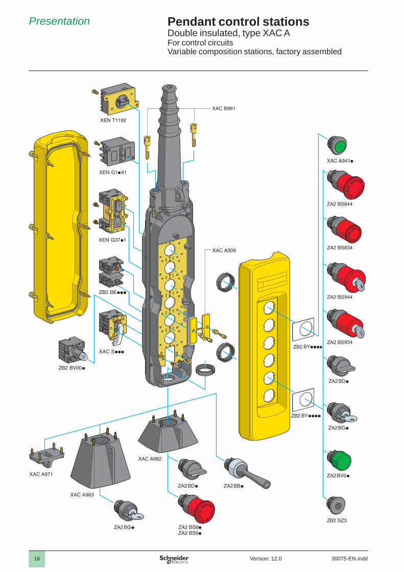
Pendant control stations 6 Double insulated, type XAC AFor control circuitsVariable composition stations, factory assembled
Presentation 6
30075-EN.inddVersion: 12.0

17
Pendant control stations 6 Double insulated, type XAC AFor control circuitsVariable composition stations, factory assembled
A
Order form (specimen suitable for photocopying) 6
Customer Schneider Electric IndustriesCompany Order N° Delivery date Sales offi ce - Subsidiary Co. Order N°
Enter the order with XAC A09 referenceUnit reference of empty enclosure, see page 30075/7 Number of identical stations Enclosure price (1)
XAC
Legendssee page 30075/12
Contact blocks or pilot light bodiessee page 30075/8
Operating heads or pilot light heads or blanking plugsee page 30075/10
Reference Unit price Reference Unit price Reference Unit price Total price1
2
3
4
5
6
7
8
9
10
11
12
Unit mounted in base of enclosure (if required) (Except when using XAC A03 and XAC A05)13
Complementary accessories, see page 30075/11 (cross the appropriate box or boxes)Description Reference Unit price
14 Adaptor for self-supporting cable type BBAP for use with cable entry sleeve Ø 8 to 26 mm
XAC B961
15 Lower support ring XAC A971
16 Protective guard for selector switch (std. handle) or Emergency stop head pushbutton, mounted in base
XAC A982
17 Protective guard for key switch or key release Emergency stop head pushbutton, mounted in base
XAC A983
Mechanical interlocking (2)Reference Quantity Unit price
XAC A009Factory assembly: Number of heads or blanking
plugs to be fi ttedAdditional cost XAC 9VA for fi tting of 1 head or 1 blanking plug
X
Total price of assembled pendant station
(1) Obtain the empty enclosure price.(2) Connect with a line the 2 ways which require mechanical interlocking.Examples: combinations possible Combinations not possible
1
2
3
4
5
11
2
3
4
5
2
3
4
5
17
16
15
13
14
1
2
3
4
5
6
7
8
9
10
12
11
30075-EN.indd Version: 12.0