characterization of high-harmonic emission from zno up to ...of+high... · high average power...
TRANSCRIPT

Characterization of high-harmonic emissionfrom ZnO up to 11 eV pumped with a Cr:ZnShigh-repetition-rate sourceGIULIO VAMPA,1,* SERGEY VASILYEV,2 HANZHE LIU,1 MIKE MIROV,2 PHILIP H. BUCKSBAUM,1
AND DAVID A. REIS1
1Stanford PULSE Institute, SLAC National Accelerator Laboratory, Menlo Park, California 94025, USA2IPG Photonics—Southeast Technology Center, Birmingham, Alabama 35211, USA*Corresponding author: [email protected]
Received 26 October 2018; revised 28 November 2018; accepted 30 November 2018; posted 30 November 2018 (Doc. ID 349143);published 4 January 2019
We report the measurement of high-order harmonics froma ZnO crystal with photon energies up to 11 eV generatedby a high-repetition-rate femtosecond Cr:ZnS laser operat-ing in the mid-infrared at 2–3 μm, delivering few-cyclepulses with multi-watt average power and multi-megawattpeak power. High-focus intensity is achieved in a single passthrough the crystal without a buildup cavity or nano-structued pattern for field enhancement. We measure inexcess of 108 high-harmonic photons/second. © 2019Optical Society of America
https://doi.org/10.1364/OL.44.000259
High\-repetition-rate femtosecond (fs) lasers at photon energies of∼10 eV and beyond are currently in high demand for applica-tions such as time-resolved photoemission [1–3], frequency-combvacuum-ultraviolet (VUV) spectroscopy [4,5], as well as time-resolved spectroscopy with chemical and elemental specificity.
The prime method to reach this spectral range is by high-order harmonic generation (HHG) driven by ultrafast infraredlasers. The high peak intensity required to generate high har-monics in noble gases, which exceeds 1014 W∕cm2, can beachieved at megahertz (MHz) repetition rates if either (i) thegas is placed inside an oscillator cavity [6] or (ii) the oscillatoroutput is coupled to an external buildup cavity that is phase-locked to the oscillator [7,8]. Coherent addition of successivepulses in the train then leads to the required field enhancement;however, the need for stable phase-locked operation of the cav-ity renders these experiments extremely challenging. Additionallimitations imposed by the dispersion of the ionized gas haveonly been circumvented recently [9]. Intense development ofhigh average power MHz-rate sources has recently enabledextra-cavity high-harmonic generation with a thin-disk oscilla-tor [10], and fs fiber lasers have also been used up to 0.6 MHz[11]. Low harmonics have also been obtained at 10 MHz [12].
An alternative to these schemes has emerged following thedemonstration of high-harmonic generation in solids [13],which have generated photon energies of 20–30 eV with
focused intensities that are 10–100 times lower than compa-rable HHG in gases [14–16]. At these reduced intensities,HHG at MHz rates becomes feasible. In an initial demonstra-tion, a conventional Ti:sapphire oscillator with a repetition rateof 75 MHz has been converted to up to 20 eV harmonics in asingle pass through sapphire nanocones coated with Au film[17]. A 100-fold enhancement of the peak intensity was ob-tained at the apex of a tapered cone by means of the metalliccoating. More recently, the output of a fs Tm-doped fiber laserhas been converted to harmonics up to 4.6 eV in a single passthrough Si and ZnO crystals without field enhancement [18].The authors concluded that a six-fold increase of the peakintensity would have been sufficient to reach 10 eV in ZnO.
Here, we generate high-order harmonics up to 11 eV pho-ton energies in a single pass through a ZnO crystal without fieldenhancement (Fig. 1). The source is a mid-infrared (MIR) fshigh-repetition-rate master oscillator power amplifier (MOPA)
6.9 8.0 9.0 10.1 11.1
High Harmonic photon energy (eV)
0
0.5
1
1.5
2
2.5
3
3.5
Pho
tons
/s p
ast t
he s
lit
106x
13 15 17 19 21
High Harmonic order
Fig. 1. High-harmonic spectrum generated by our high-repetition-rate Cr2�:ZnS laser system. The high-harmonic spectrum covers thespectral range between ∼6 and ∼12 eV. The yellow spectrum isobtained with a Pt-coated grating.
Letter Vol. 44, No. 2 / 15 January 2019 / Optics Letters 259
0146-9592/19/020259-04 Journal © 2019 Optical Society of America
based on a Cr2�:ZnS gain medium, which delivers three-cyclepulses at a central wavelength of 2.34 μm and a pulse energyof 79 nJ.
The paper is organized as follows. First, we present the capa-bilities of the laser system employed in this study. Second, wedetail the experimental setup for the high-harmonic measure-ments and report the measured photon flux. Finally, we drawthe conclusions.
A MIR fs laser source is arranged as a full-repetition-rateMOPA. It is purpose-built for high-harmonic generation andoptimized for short pulse duration. The schematic of the sourceis illustrated in Fig. 2 with the output parameters in Fig. 3.The design of the generic scheme is described in Ref. [19].
The plane-parallel cut, AR-coated gain elements are opticallypumped by off-the-shelf cw Er-doped fiber lasers (EDFLs)and cooled with room-temperature water. Both the master os-cillator and the amplifier are based on polycrystalline Cr2�:ZnSproduced in-house. The Cr2�:ZnS oscillator delivers 1.1 Waverage power at 76.4 MHz pulse repetition frequency (f R)[20] over a bandwidth of 320 nm [14 THz, FWHM, Fig. 3(a)].The estimated transform-limited pulse duration is τ�S� ≈ 19 fs,assuming the time-bandwidth product is 0.32. The averagepower for the amplified MIR fs pulses exceeds 6 W, which cor-responds to 26% single-pass conversion of low-cost cw EDFLradiation. Nonlinear χ�3� interactions in the amplifier’s gainelement [21] result in spectral broadening of the amplifiedpulses to about 450 nm [23 THz, FWHM, Fig. 3(a)]. A signifi-cant fraction of theMIRoutput is converted to second harmonicvia the random quasi-phase-matching (RQPM) process in thepolycrystalline gain element. We measure second-harmonicgeneration (SHG) power in excess of 0.4W. More details aboutthe spectral broadening of fs seed pulses in the amplifier’s gainelement are provided in Fig. 27 of Ref. [19].
Few-cycle MIR pulses acquire significant temporal broaden-ing and chirp during their propagation through a 3.2 mmyttrium aluminum garnet (YAG) substrate of the oscillator’soutput coupler (OC) and the 9-mm-thick Cr2�:ZnS gainelement of the amplifier. For instance, presumed τ�S� ≈ 19 fsoutput of the oscillator is broadened to about τ�AC� � 80 fsby the OC with group delay dispersion (GDD) ≈ − 480 fs2
[Fig. 3(b)]. The Cr2�:ZnS gain element has higher dispersionwith the opposite sign (GDD ≈� 1120 fs2). We use a pair ofdispersive mirrors (M*, GDD ≈ − 280 fs2) for coarse dispersioncontrol, and one 4-mm-thick YAG Brewster plate with negativeGDD (−492 fs2) for fine-tuning of the output pulses. As aresult, we measure τ�AC� � 29 fs pulse duration at the outputof the “cold” amplifier (i.e., with its pump turned off ), asshown in Fig. 3(c). Nonlinear spectral broadening inside the“hot” amplifier results in further reduction of the pulse dura-tion to 26 fs [see Fig. 3(d)]. Thus, we obtain three-cycle pulsesat 2.4 μm central wavelength with 79 nJ energy and 2.7 MWpeak power at f R � 76.4 MHz.
Measured durations of the re-compressed pulses exceed thelimits τ�S� that can be derived from their spectra, assumingsech2 profiles. This discrepancy is mostly due to significant un-compensated third-order dispersion. The limited dispersioncontrol (over one third of an octave [20,21]) of the availabledielectric coatings in the MIR range between 2 and 3 μm cur-rently limit our Cr2�:ZnS oscillators and amplifiers. Recentprogress in the technology of MIR coatings will allow us toachieve two-cycle and even sub-two-cycle pulses in the nearfuture. Furthermore, the average power is limited by thermal-optical effects in the gain elements [19]. The recent advent ofthe spinning ring Cr2�-based lasers and amplifiers has allowedus to mitigate the thermal roll-off and achieve 140 W averagepower in the cw regime [22] and 27 W power in a 60 fs (eight-cycle) regime [23].
The setup employed to generate high-order harmonics isdescribed below. The output beam of the MOPA is expandedby a telescope composed of a concave mirror (f � 200 mm,Au) and a plano-convex lens (CaF2, f � 250 mm, AR coated)and is focused inside a vacuum chamber with a Au-coated 90°off-axis parabola with a nominal f ∕# � 1.2. The focused beam
9 mm Cr:ZnScw EDFL
18 W
cw EDFL7 W
LM*
M*
DM
DM
Cr:ZnS MO1.1 W, 29 fs
6 W, 26 fsBP
SHG
ResidualPump
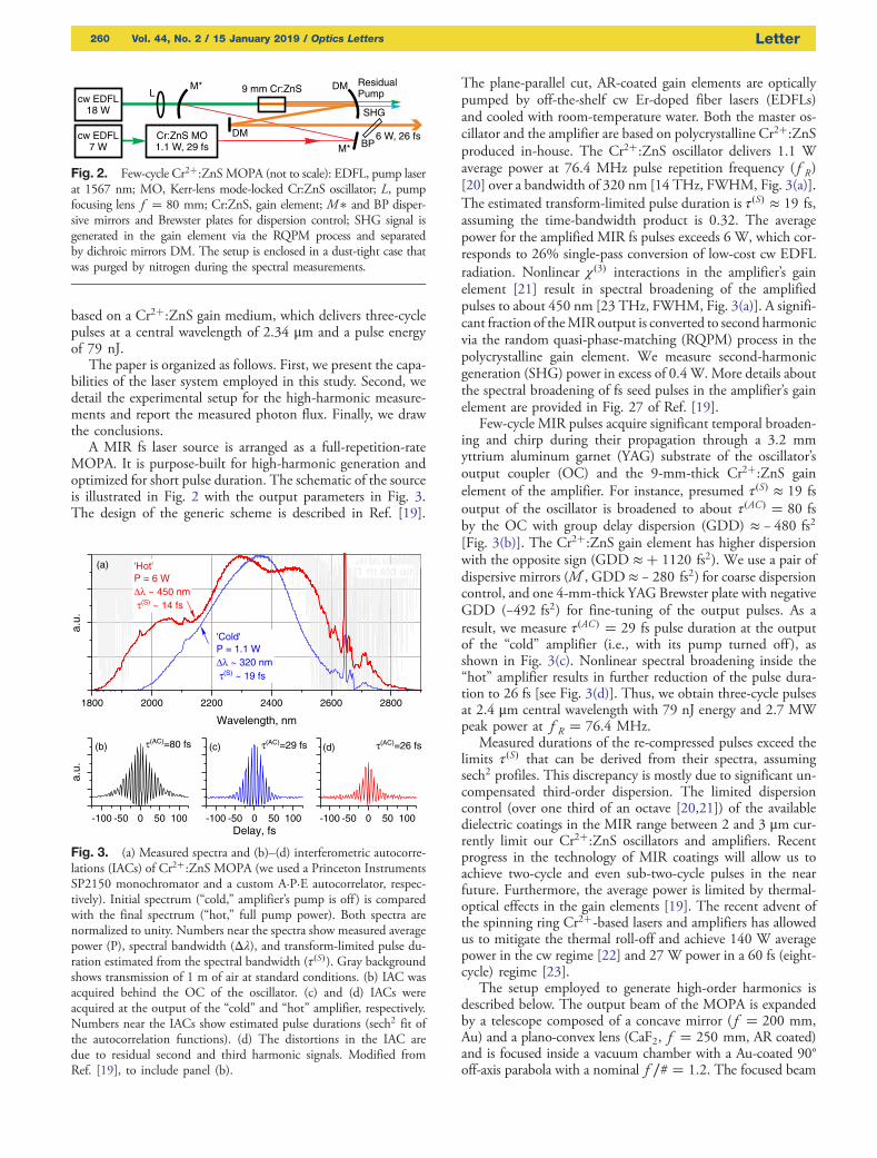
Fig. 2. Few-cycle Cr2�:ZnSMOPA (not to scale): EDFL, pump laserat 1567 nm; MO, Kerr-lens mode-locked Cr:ZnS oscillator; L, pumpfocusing lens f � 80 mm; Cr:ZnS, gain element; M� and BP disper-sive mirrors and Brewster plates for dispersion control; SHG signal isgenerated in the gain element via the RQPM process and separatedby dichroic mirrors DM. The setup is enclosed in a dust-tight case thatwas purged by nitrogen during the spectral measurements.
1800 2000 2200 2400 2600 2800
'Cold'P = 1.1 W Δλ ~ 320 nm τ(S) ~ 19 fs
'Hot'P = 6 W Δλ ~ 450 nm τ(S) ~ 14 fs
(a)
a.u.
Wavelength, nm
1 m std air
-100 -50 0 50 100
a.u.
(b) τ(AC)=80 fs
-100 -50 0 50 100
τ(AC)=29 fs(c)
Delay, fs-100 -50 0 50 100
τ(AC)=26 fs(d)
Fig. 3. (a) Measured spectra and (b)–(d) interferometric autocorre-lations (IACs) of Cr2�:ZnS MOPA (we used a Princeton InstrumentsSP2150 monochromator and a custom A·P·E autocorrelator, respec-tively). Initial spectrum (“cold,” amplifier’s pump is off ) is comparedwith the final spectrum (“hot,” full pump power). Both spectra arenormalized to unity. Numbers near the spectra show measured averagepower (P), spectral bandwidth (Δλ), and transform-limited pulse du-ration estimated from the spectral bandwidth (τ�S�). Gray backgroundshows transmission of 1 m of air at standard conditions. (b) IAC wasacquired behind the OC of the oscillator. (c) and (d) IACs wereacquired at the output of the “cold” and “hot” amplifier, respectively.Numbers near the IACs show estimated pulse durations (sech2 fit ofthe autocorrelation functions). (d) The distortions in the IAC aredue to residual second and third harmonic signals. Modified fromRef. [19], to include panel (b).
260 Vol. 44, No. 2 / 15 January 2019 / Optics Letters Letter
passes through a 0.5-mm-thick ZnO single crystal �112̄0� cut.The generated high-harmonic beam is spatially and spectrallyanalyzed by a VUV spectrometer (McPherson 234) equippedwith interchangeable aberration-corrected concave diffractiongratings. An Al-coated grating with 1200 l/mm is suitable forphoton energies below 10 eV, while a Pt-coated grating with2400 l/mm is used for higher photon energies. The diffractedbeam is recorded with a Si CCD (Andor, model DO-420-BN). To reduce absorption of the ultraviolet radiation, thechambers are kept at a base pressure of ∼1 × 10⁻² mbar.
To generate high-order harmonics, the focus is positionedtowards the exit surface of the crystal, and the laser power istuned to 2.55 W (∼50% of the nominal power) to avoidmaterial damage. The high-harmonic flux is maximized with(i) optimal compression of the pulses in the crystal and (ii) op-timal focusing by tuning the separation between the telescope’smirror and lens. This latter procedure minimizes the f ∕# whilepreserving the power transmitted by the optics. The pulse du-ration is optimized by replacing the 4-mm-thick YAG plate(GDD � −492 fs2) with a 4-mm-thick CaF2 plate, bringingthe total GDD of the setup to −522 fs2 (�6%). The peak in-tensity in vacuum is calculated from the measured input power,the shortest pulse duration of the laser system [26 fs, Fig. 3(d)],and the focus size (w0 � 6.7 μm1∕e2 radius). The focus waist ismeasured with an objective lens [Mitutoyo Plan APONIR infin-ity corrected, NA � 0.42] and a piezo-electric line array(Pyreos), and the finite resolution of the objective (1.7 μm)is deconvoluted. The estimated peak intensity in vacuum is∼1 × 10¹² W∕cm2. Although incubation at MHz repetitionrates may cause thermal melting once the optical breakdownthreshold is exceeded [24], the reason for ZnO damage has notbeen investigated here and is generally not well understood yet.
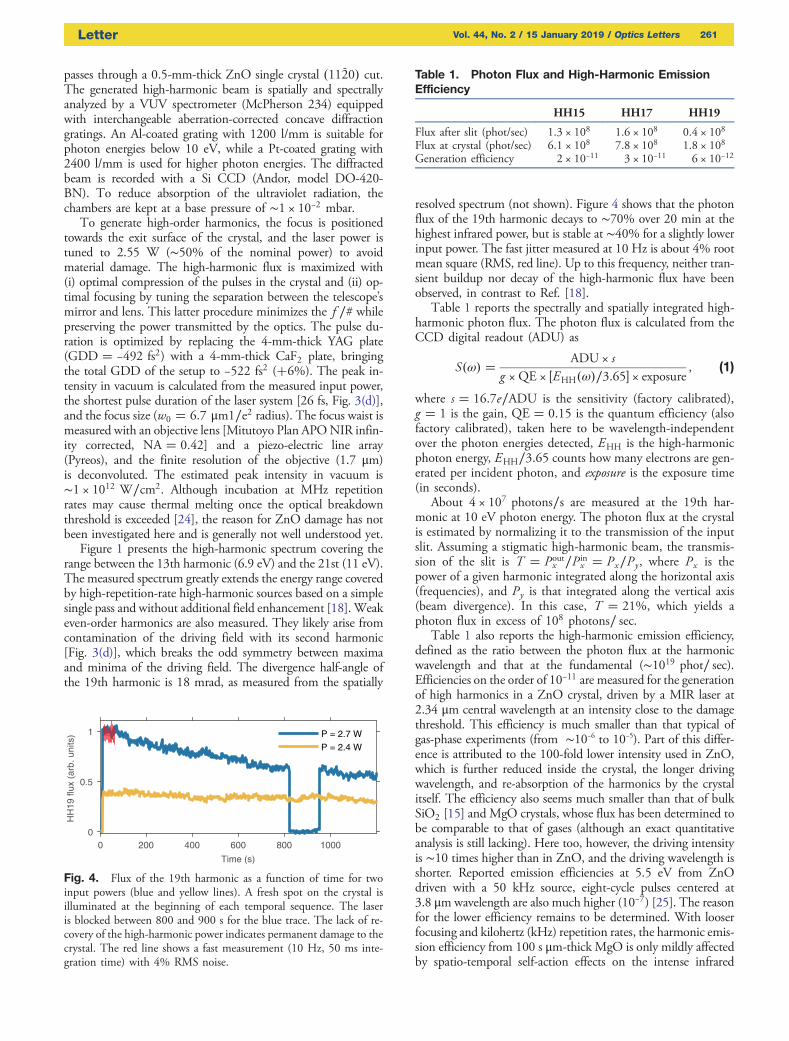
Figure 1 presents the high-harmonic spectrum covering therange between the 13th harmonic (6.9 eV) and the 21st (11 eV).The measured spectrum greatly extends the energy range coveredby high-repetition-rate high-harmonic sources based on a simplesingle pass and without additional field enhancement [18].Weakeven-order harmonics are also measured. They likely arise fromcontamination of the driving field with its second harmonic[Fig. 3(d)], which breaks the odd symmetry between maximaand minima of the driving field. The divergence half-angle ofthe 19th harmonic is 18 mrad, as measured from the spatially
resolved spectrum (not shown). Figure 4 shows that the photonflux of the 19th harmonic decays to ∼70% over 20 min at thehighest infrared power, but is stable at ∼40% for a slightly lowerinput power. The fast jitter measured at 10 Hz is about 4% rootmean square (RMS, red line). Up to this frequency, neither tran-sient buildup nor decay of the high-harmonic flux have beenobserved, in contrast to Ref. [18].
Table 1 reports the spectrally and spatially integrated high-harmonic photon flux. The photon flux is calculated from theCCD digital readout (ADU) as
S�ω� � ADU × sg ×QE × �EHH�ω�∕3.65� × exposure
, (1)
where s � 16.7e∕ADU is the sensitivity (factory calibrated),g � 1 is the gain, QE � 0.15 is the quantum efficiency (alsofactory calibrated), taken here to be wavelength-independentover the photon energies detected, EHH is the high-harmonicphoton energy, EHH∕3.65 counts how many electrons are gen-erated per incident photon, and exposure is the exposure time(in seconds).
About 4 × 10⁷ photons∕s are measured at the 19th har-monic at 10 eV photon energy. The photon flux at the crystalis estimated by normalizing it to the transmission of the inputslit. Assuming a stigmatic high-harmonic beam, the transmis-sion of the slit is T � Pout
x ∕P inx � Px∕Py, where Px is the
power of a given harmonic integrated along the horizontal axis(frequencies), and Py is that integrated along the vertical axis(beam divergence). In this case, T � 21%, which yields aphoton flux in excess of 108 photons∕ sec.
Table 1 also reports the high-harmonic emission efficiency,defined as the ratio between the photon flux at the harmonicwavelength and that at the fundamental (∼1019 phot∕ sec).Efficiencies on the order of 10−11 are measured for the generationof high harmonics in a ZnO crystal, driven by a MIR laser at2.34 μm central wavelength at an intensity close to the damagethreshold. This efficiency is much smaller than that typical ofgas-phase experiments (from ∼10−6 to 10−5). Part of this differ-ence is attributed to the 100-fold lower intensity used in ZnO,which is further reduced inside the crystal, the longer drivingwavelength, and re-absorption of the harmonics by the crystalitself. The efficiency also seems much smaller than that of bulkSiO2 [15] and MgO crystals, whose flux has been determined tobe comparable to that of gases (although an exact quantitativeanalysis is still lacking). Here too, however, the driving intensityis ∼10 times higher than in ZnO, and the driving wavelength isshorter. Reported emission efficiencies at 5.5 eV from ZnOdriven with a 50 kHz source, eight-cycle pulses centered at3.8 μmwavelength are also much higher (10−7) [25]. The reasonfor the lower efficiency remains to be determined. With looserfocusing and kilohertz (kHz) repetition rates, the harmonic emis-sion efficiency from 100 s μm-thick MgO is only mildly affectedby spatio-temporal self-action effects on the intense infrared
0 200 400 600 800 1000
Time (s)
0
0.5
1
HH
19 fl
ux (
arb.
uni
ts) P = 2.7 W
P = 2.4 W
Fig. 4. Flux of the 19th harmonic as a function of time for twoinput powers (blue and yellow lines). A fresh spot on the crystal isilluminated at the beginning of each temporal sequence. The laseris blocked between 800 and 900 s for the blue trace. The lack of re-covery of the high-harmonic power indicates permanent damage to thecrystal. The red line shows a fast measurement (10 Hz, 50 ms inte-gration time) with 4% RMS noise.
Table 1. Photon Flux and High-Harmonic EmissionEfficiency
HH15 HH17 HH19
Flux after slit (phot/sec) 1.3 × 10⁸ 1.6 × 10⁸ 0.4 × 10⁸Flux at crystal (phot/sec) 6.1 × 10⁸ 7.8 × 10⁸ 1.8 × 10⁸Generation efficiency 2 × 10⁻¹¹ 3 × 10⁻¹¹ 6 × 10⁻¹²
Letter Vol. 44, No. 2 / 15 January 2019 / Optics Letters 261
driver [26]. By analogy, crystal thickness in this experimentshould not significantly affect the emission efficiency. Further-more, in our experience, tight focusing towards the exit surfacehelps mitigate propagation effects.
In conclusion, we have demonstrated solid-state HHG intothe VUV at 76 MHz repetition rate using a Cr2�:ZnSMOPA.The long MIR wavelength is suitable for the excitation of lowto wide bandgap materials with high field strength, withoutincurring deleterious few-photon absorption and the ensuingdecrease of the damage threshold. The relatively high pulse en-ergy enables the conversion of MIR light to short-wavelengthradiation in a simple single pass through the crystal, withoutfield enhancement provided by nanopatterned surfaces orbuildup cavities. Moreover, we have characterized the high-harmonic photon flux from a ZnO crystal to be ∼108 photons/sec/harmonic and extracted a conversion efficiency of about10−11 per harmonic, which is orders of magnitude lower thantypical gas-phase experiments. Our measurements are a testbedfor theoretical work aimed at a quantitative analysis of ioniza-tion rates and high-harmonic emission efficiency in solids. Ourdemonstration of high-repetition-rate high harmonics eases theinvestigation of strong-field phenomena in nanoscale and low-dimensional solids, where the detected photon flux is limited bythe small emission volume.
Progress in thermal dissipation and in MIR dispersivedielectric coatings [27] promise to reach intensities beyondthe 10 TW∕cm2 level, thereby enabling excitation of widerbandgap materials such as MgO and SiO2, where generationof 20–30 eV high harmonics has been demonstrated only withlow-repetition-rate amplified laser systems. We foresee thatCr2�-doped high-power lasers will become the workhorse ofstrong-field science in solids in the near future, taking the stagethat once belonged to Ti:sapphire amplified systems.
Finally, the high high-harmonic photon energy is useful forfrequency-comb spectroscopy with greater precision thancurrently possible. For applications to comb spectroscopy,we calculate that the photon flux in each tooth of the combis ≳ 700 photons∕ sec ∕tooth at the 17th harmonic.
Funding. W. M. Keck Foundation.
Acknowledgment. This work is supported by the W. M.Keck Foundation and Stanford University. The authors thankthe Stanford Photonic Research Center and IPG Photonics forequipment gifts and R. Coffee for equipment loans.
REFERENCES
1. A. K. Mills, S. Zhdanovich, F. Boschini, M. Na, M. Schneider, P.Dosanjh, D. Wong, G. Levy, A. Damascelli, and D. J. Jones, inCLEO: Science and Innovations (Optical Society of America, 2017),p. STu1I–2.
2. C. Corder, P. Zhao, X. Li, M. D. Kershis, M. G. White, and T. K. Allison,Proc. SPIE 10519, 105190B (2018).
3. P. Miotti, F. Cilento, R. Cucini, A. De Luisa, A. Fondacaro, F.Frassetto, D. Kopi, D. Payne, A. Sterzi, T. Pincelli, G. Panaccione,F. Parmigiani, G. Rossi, and L. Poletto, in Compact EUV & X-rayLight Sources (Optical Society of America, 2018), p. EW2B–5.
4. R. T. Zinkstok, S. Witte, W. Ubachs, W. Hogervorst, and K. S. Eikema,Phys. Rev. A 73, 061801 (2006).
5. A. Cingöz, D. C. Yost, T. K. Allison, A. Ruehl, M. E. Fermann, I. Hartl,and J. Ye, Nature 482, 68 (2012).
6. F. Labaye, M. Gaponenko, V. J. Wittwer, A. Diebold, C. Paradis, N.Modsching, L. Merceron, F. Emaury, I. J. Graumann, C. R. Phillips,C. J. Saraceno, C. Kränkel, U. Keller, and T. Südmeyer, Opt. Lett.42, 5170 (2017).
7. I. Pupeza, S. Holzberger, T. Eidam, H. Carstens, D. Esser, J.Weitenberg, P. Rußbüldt, J. Rauschenberger, J. Limpert, T. Udem,A. Tünnermann, T. W. Hänsch, A. Apolonski, F. Krausz, and E.Fill, Nat. Photonics 7, 608 (2013).
8. A. K. Mills, T. Hammond, M. H. Lam, and D. J. Jones, J. Phys. B 45,142001 (2012).
9. G. Porat, C. M. Heyl, S. B. Schoun, C. Benko, N. Dörre, K. L. Corwin,and J. Ye, Nat. Photonics 12, 387 (2018).
10. F. Emaury, A. Diebold, C. J. Saraceno, and U. Keller, Optica 2, 980(2015).
11. S. Hädrich, A. Klenke, J. Rothhardt, M. Krebs, A. Hoffmann, O. Pronin,V. Pervak, J. Limpert, and A. Tünnermann, Nat. Photonics 8, 779(2014).
12. P. Storz, J. Tauch, M. Wunram, A. Leitenstorfer, and D. Brida, LaserPhoton. Rev. 11, 1700062 (2017).
13. S. Ghimire, A. D. DiChiara, E. Sistrunk, P. Agostini, L. F. DiMauro, andD. A. Reis, Nat. Phys. 7, 138 (2011).
14. Y. S. You, D. A. Reis, and S. Ghimire, Nat. Phys. 13, 345 (2017).15. T. T. Luu, M. Garg, S. Y. Kruchinin, A. Moulet, M. T. Hassan, and E.
Goulielmakis, Nature 521, 498 (2015).16. G. Ndabashimiye, S. Ghimire, M. Wu, D. A. Browne, K. J. Schafer,
M. B. Gaarde, and D. A. Reis, Nature 534, 520 (2016).17. S. Han, H. Kim, Y. W. Kim, Y.-J. Kim, S. Kim, I.-Y. Park, and S.-W.
Kim, Nat. Commun. 7, 13105 (2016).18. K. F. Lee, X. Ding, T. Hammond, M. Fermann, G. Vampa, and P.
Corkum, Opt. Lett. 42, 1113 (2017).19. S. B. Mirov, I. S. Moskalev, S. Vasilyev, V. Smolski, V. V. Fedorov, D.
Martyshkin, J. Peppers, M. Mirov, A. Dergachev, and V. Gapontsev,IEEE J. Sel. Top. Quantum Electron. 24, 1 (2018).
20. S. Vasilyev, I. Moskalev, M. Mirov, S. Mirov, and V. Gapontsev, Opt.Lett. 40, 5054 (2015).
21. S. Vasilyev, I. Moskalev, M. Mirov, V. Smolski, S. Mirov, and V.Gapontsev, Opt. Mater. Express 7, 2636 (2017).
22. I. Moskalev, S. Mirov, M. Mirov, S. Vasilyev, V. Smolski, A.Zakrevskiy, and V. Gapontsev, Opt. Express 24, 21090 (2016).
23. S. Vasilyev, I. Moskalev, V. Smolski, J. Peppers, M. Mirov, S. Mirov,and V. Gapontsev, Adv. Solid State Lasers Conference (2018),p. AW3A.1.
24. C. B. Schaffer, J. F. Garca, and E. Mazur, Appl. Phys. A 76, 351(2003).
25. S. Gholam-Mirzaei, J. Beetar, and M. Chini, Appl. Phys. Lett. 110,061101 (2017).
26. G. Vampa, Y. You, H. Liu, S. Ghimire, and D. Reis, Opt. Express 26,12210 (2018).
27. V. Pervak, T. Amotchkina, Q. Wang, O. Pronin, K. Mak, and M.Trubetskov, Adv. Solid State Lasers Conference (2018), p. AW3A.2.
262 Vol. 44, No. 2 / 15 January 2019 / Optics Letters Letter