characterization of laminar flame using high speed camera
TRANSCRIPT

Characterization of laminar flame using high speed cameraand spectrometer
MANASA RAM KOTAL , SOMNATH DE* , SOUMYADEEP DAS and SWARNENDU SEN
Department of Mechanical Engineering, Jadavpur University, Kolkata 700032, India
e-mail: [email protected]
MS received 15 April 2018; revised 11 January 2019; accepted 18 March 2019
Abstract. In order to improve flame stabilization in small scale combustors, there have been many research
works going on non-premixed as well as on premixed flame. The present experimental study characterizes
colour and shape of the premixed and non-premixed flames through a laminar co-flow burner. Various flame
behaviors are observed and their stabilization limits are investigated at different fuel–air ratios. The spectro-
scopic approach becomes suitable method for the measurement of chemiluminescensce for both premixed and
diffusion flames. Thus, we can predict the behavior of a combustion process. We observe also the intensity
variation of chemiluminescence species, OH*, CH*, and C2* for different fuel-air flow combinations. Apart
from that, we have an analysis of colour variance of the premixed flame for different flame locations.
Keywords. Non-premixed flame; premixed flame; co-flow laminar burner; Reynolds number;
chemiluminescence.
1. Introduction
Most of the combustion industries are facing some new
challenges in order to increase the efficiency, reliability and
flexibility of combustion equipment. To meet those
demands we have to focus for better concepts and improved
designs. Now a days, new burner optimization and super-
vision of various types of combustion flames, used in dif-
ferent combustion industries, play a vital role to minimize
the difficulties, raised in the industry. These concepts are
one of the key technological objectives, which are recog-
nized in surveys and roadmaps proposed for different
combustion applications [1]. However, permanent opti-
mization of combustors is currently very limited. Laminar
co-flow burner is one of the most useful combustors in
these aspects. The simple design with a basic tube-in-tube
configuration and minimum maintenance requirement
offers a fundamental study on the laminar flames.
The observation and control of most practical burners are
based on the fossil fuel, apart from the works, which have
been carried out on the basis of analysis of flue gases [2].
This system has taken into consideration to achieve the
desired excess air or to check the levels of undesirable
emissions (e.g., CO, NOx, particulates). To keep the
emission level within the permissible range, modern
research has adopted the low NOx combustion, which
includes lean premixed combustion [3, 4]. On the other
hand, diffusion flame is being pursued conventionally in
existing gas turbine engines due to their inherent
stable characteristics and reliable performance. Premixed
and non-premixed laminar flame studies have been carried
out employing a wide range of fuels and with even fuel
blends [5].
However, most of the experimental works on the fun-
damental understanding of the combustion behavior of
gaseous and liquid fuels have been carried out in laminar
flame burners. Both laminar premixed and non-premixed
flames have applications in several heating appliances,
burners, ovens and many other commercial and industrial
devices. Apart from this, most of the practical combustion
systems such as gas turbine engines, rocket combustors, etc.
employ non-premixed combustion to maintain better flame
stability, safety, and wide operating range as compared to
premixed combustion. In the case of non-premixed flame, it
is quite stable over a wide range of operating parameters.
However, it produces soot, nitrogen dioxide, and carbon
monoxide and results in less combustion efficiency in few
cases. The main reason to use a laminar flame for research
works is to avoid the complications introduced by turbulent
fluctuations which require time-resolved measurements for
their characterization. On the other side, laminar flames
permit line-of-sight diagnostic methods and offer high
potential for application and development of advanced laser
This paper is a revised and expanded version of an article presented in
‘‘First International Conference on Mechanical Engineering’’ held at
‘Jadavpur University’, Kolkata, India during January 4–6, 2018
(INCOM-2018).
*For correspondence
Sådhanå (2020) 45:230 � Indian Academy of Sciences
https://doi.org/10.1007/s12046-020-01465-4Sadhana(0123456789().,-volV)FT3](0123456789().,-volV)

measurement techniques. Miller and Maahs [6] have been
referred to as one of the pioneers to work on laminar non-
premixed flames at high pressures. They have calculated
NOx and temperatures in a co-flow burner.
The gradual depletion of fossil fuels and the growing
concern about the reduction of pollutant emissions, espe-
cially of CO2, due to its participation in the greenhouse
effect, have promoted the use of new fuels, such as those
produced in the gasification of solid fuels (coal, biomass,
residues) or from other non-conventional sources, such as,
industrial byproducts (e.g., refinery gas) or biogas produced
by anaerobic digestion processes. On the other hand, the
environmental problems caused by vehicle exhaust emis-
sions become more problematic. Fuel economy standards
become more stringent. Thus, an alternative fuel engine
technology is needed to cope with the new requirements
and regulations. LPG is one of the best alternatives because
it can be liquefied in a low-pressure range of 0.7–0.8 MPa
at atmospheric temperature [7]. Mostly it is nontoxic,
noncorrosive, and free of tetra-ethyl lead, and it has a
higher-octane rating. LPG fuel also has a higher heating
value compared with other fuels [8]. Several studies were
reported on LPG–air premixed and diffusion flames. A
study on the flammability limits of the LPG–air mixture
was done experimentally by Mishra and Rehman [9]. Fuel
property of LPG for transportation was reported by
Demirbas [10].
To analyze, and describe the behavior of an LPG–air
mixed flame, measurement of chemiluminescence plays a
crucial role as it is non-intrusive and directly proportional
to the heat release rate [11]. Chemiluminescence is
nothing but the light emitted by the flame. To complete
one global reaction, several intermediate reactions and
several numbers of intermediate species are involved.
The reactive radicals or excited radicals having unpaired
electrons emit light when they come down to the lower
energy state. For the measurement of chemiluminescence,
we need a sensor which can collect the analog signal
from the flame and also digitalize the signal to predict
the behavior of a combustion process. The close rela-
tionship between combustion control and sensors is
clearly implicit in the review by Docquier and Candel
[12]. Conventional instruments are customarily used to
measure global variables, such as input flow rates and
flue gas composition (e.g., O2, CO, NOx, SO2), but they
afford a very limited description of the process taking
place inside the combustion chamber. Therefore, the
development of such flame monitoring techniques suit-
able for practical applications appears as an important
prerequisite for the design of ambitious supervision and
control strategies of combustion equipment. The general
concept of a flame monitoring technique actually includes
diverse applications (in terms of the characteristics of the
combustion equipment and monitoring objectives) and
can be based on various types of sensors as well as on
widely different approaches for the interpretation and use
of sensorial information. The importance of sensors in
flame monitoring process to improve the capabilities and
reliability of combustion control strategies has been dis-
cussed in a number of previous works [13–15].
The chemiluminescent species involved in the premixed
and diffusion flames are basically OH* (wavelength around
308 nm), CH* (wavelength around 431 nm), C2* (wave-
length lies in the swan band, 436 nm to 563 nm) and CO2*
(basically in the infrared region, 2800 nm to 4400 nm).
Various numerical and experimental studies are conducted
on chemiluminescence based heat release rate prediction of
flames. Samaniego et al [16] predicted the heat release rate
over the entire domain using CO2* emitted chemilumi-
nescence in vortex induced, methane–air and propane–air
premixed turbulent flames. Hardalupas et al [17] showed
that CO2* could be a good predictor of heat release rate
instead of C2* in natural gas-air premixed flames. Numer-
ically they found that C2* and CO2* might not be the best
indicator of heat release rate of a flame under a wide range
of conditions. They also found that OH* and CH* radicals
were good indicators of heat release rate of flame. The
relationships observed between chemiluminescence inten-
sities and flame properties can be exploited to perform
different combustion diagnostics [18]. In particular, cali-
bration curves relating the selected chemiluminescence
parameters with equivalence ratios could be used to
develop on-line flame stoichiometry sensors. Different
methods of chemiluminescence measurement have been
tested using simple photo sensors such as photomultiplier
tubes, photodiodes or spectrometers [19–24] or CCD
cameras [25] and tomographic techniques [26] in earlier
combustion studies.
The main goal of our study is to visualize the
dynamics of both premixed and non-premixed flames at
different LPG–air ratios using a co-flow burner. Apart
from that, a detail radical (OH*, CH*, C2*) analysis is
done at different flow conditions (Re). Also, a discussion
is made on the changes in flame colour using a spec-
trometer [18] as it can capture the wavelength band of
the visible range. The rest of the paper is organized as
follows. A description of the experimental set-up and
procedure is provided in section 2. The results are dis-
cussed in section 3. Finally, the major findings are
summarized in section 4.
2. Experimental set-up
2.1 Premixed configuration
The main part of the setup is laminar co-flow burner which
has an inner tube enclosed by an outer tube (figures 1 and
2). In this configuration, we observe the flame colour and
behavior of the premixed flame at different air fuel ratios.
The delivery pipe of the LPG cylinder is connected to the
inlet section of the mass flow controller (Alborg MFC CH4,
230 Page 2 of 11 Sådhanå (2020) 45:230

0–10 LPM, calibrated for LPG), by which we control and
regulate the flow of LPG (liquefied petroleum gas, 60%
butane and 40% propane, by volume). On the other hand,
air comes from a compressor and enters into the mixing
chamber after being metered by the air mass flow controller
(Alborg MFC for air, range: 0–50 LPM). Finally, fuel-air
mixture from the mixing chamber goes to the burner
through an inner tube (figure 1).
2.2 Non-premixed configuration
In this section, we use another arrangement similar to the
premixed configuration except the air path. Similar to ear-
lier, LPG comes from the LPG cylinder and flow rate is
metered by a mass flow controller. Then, it passes through
the inner core of the co-flow burner. On the other hand, air
comes from a compressor and enters into the annular sec-
tion of the co-flow burner after being metered by a mass
flow controller. The mixing chamber is not used here.
In this configuration, we want to see the variation of the
behavior of the diffusion flame. In this study, it is planned
to follow the variation of the flow process in which (a) fuel
pipe is connected to the inner tube of the burner and air is
connected to the outer tube of the burner, (b) fuel is con-
nected to the outer tube and air is connected to the inner
tube of the burner. Another observation, we have taken into
consideration in the study that is a spectrograph by which
we want to see the variety of colour intensity as well as for
radical analysis.
2.3 Process to capture chemiluminescenceand flame colour
Spectrometry is the study of interactions between the
chemical reactions and measurements of radiation intensity
of the excited molecules. It is a quantitative measurement
of the reflection or transmission properties of a material as a
function of wavelength. The study deals with visible light,
near-ultra violet, and near-infrared regions. In this work, an
Ava spec 2048 fiber optic spectrometer (signal/
noise = 200:1, 16-bit AD converter, range 200–1100 nm),
which is based on the Czerny-Turner design with
2048-pixel CCD Detector Array, is used. The Ava spec
2048 (USB2) runs on USB power and data of the signal is
stored in a file after being processed through Avaspec
software based programme (Avantes).
Spectroscopy is a general methodology that can be
adapted in many ways to extract the information we need
(energies of electronic, vibrational states, rotational states,
structure and symmetry of molecules, dynamic informa-
tion). It allows us to better understand electromagnetic
radiation like light. The basic thing in this method is to
Figure 1. The schematic of a premixed burner is shown. In such configuration, air–fuel mixture is sent through the inner tube as pointed
out in the figure. The same setup is used for the non-premixed flame where fuel enters through the inner tube and air is sent through the
annular section. The annular co-flow region contains a honeycomb to provide a uniform exit velocity profile.
Sådhanå (2020) 45:230 Page 3 of 11 230

capture the signal in terms of intensity of different colours
at different wavelengths emitted by the flame. Also, a
digital camera (Nikon J5) is used to capture the behavior of
the flame.
3. Results and discussion
3.1 Dynamics of the flame
3.1a Premixed flame: The movie clips of the flames are
grabbed by a digital camera for the duration of 15–20 s and
are split into 2-D image frames using our in-house code.
Each snapshot of the flame indicates the complex behavior
of the combustion. The experiments have been performed
with LPG as fuel in the co-flowing streams issued from the
burner. Figure 3 shows the different combustion situations
at various flow conditions (indicated by Reynolds number).
A typical double flame structures have been analyzed from
the images (figures 3ii–iv). In this study, we change both
fuel and air flow rates in order to get a flow matrix.
At Re 1200, we identify a soot regime where the flow
contains high flow rate of fuel as well as air. An important
observation is captured at Re 1100 (figure 3ii). An inner rich
premixed flame,which is shorter in length, is surrounded by a
partially premixed flame. The soot is noticed at the tip of the
inner flame.We observe the influence of yellow colour due to
the soot formation. Amajor portion of incoming unburnt fuel
is burned close to the tip of the inner tube. The rest of the
unburnt fuel gets mixed with the surrounding air, which
results in formation of a bluish partially premixed flame.
Partially premixed flames are different classes of the flame
which have widespread practical applications (e.g., in gas
turbines, internal combustion engines). At low Re
(Re = 975, where air flow rate is 10 LPM and fuel flow rate
is 1 LPM), double flame structure becomes more prominent.
Due to the richness in fuel, the maximum luminosity exists at
the tip of the inner tube.
3.1b Non-premixed flame: In the first case (figure 4i), air
and LPG flow rates are kept at 25 LPM and 0.25 LPM,
respectively. We observe a stable laminar flame, but the
equivalence ratio is quite less as it is a lean mixture. Now if
we increase the value of the fuel flow rate, we see that Re
increases and also equivalence ratio increases. Also, the
structure of the laminar flame deforms (figures 4ii–iv). At
LPG 1.0 LPM and air 25 LPM, we see that equivalence
ratio goes above the stoichiometric ratio. From there, with
increasing fuel rate Re crosses the value of 2000, which is
not desirable for that experiment as we want to study
laminar flame. The colour of the flame is seen as typical
yellow (like candle flame).
3.1c Non-Premixed flame (inversed): In most of the cases,
inner tube and outer annular section of the co-flow burner
Figure 2. Schematic of the co-flow burner and the locations of spectrometer kept for capturing the intensity of different excited species.
230 Page 4 of 11 Sådhanå (2020) 45:230

Figure 3. Snapshots of premixed flame at different flow conditions: (i) Re = 1200, (ii) Re = 1100, (iii) Re = 1009, and (iv)
Re = 975.
Figure 4. Typical snapshots of non-premixed flame at different flow conditions: (i) Re = 1772, (ii) Re = 1806, (iii) Re = 1840, and
(iv) Re = 1874.
Table 1. Formation routes of excited radicals and characteristic wavelengths.
Radical Reactions Wavelength (nm)
OH* R1: CH ? O2 � CO ? OH*
R2: H ? O ? M � OH* ? M
R3: O(H) ? OH ? H � H2O ? OH*
282.9, 308.9
CH* R4: C2H ? O2 � CO2 ? CH*
R5: C2H ? O � CO ? CH*
387.1, 431.4
C2* R6: CH2 ? C � C2* ? H2 515.8, 516
CO2* R7: CO ? O ? M � CO2* ? M Continuous spectrum in visible range (350–600)
Sådhanå (2020) 45:230 Page 5 of 11 230

(shown in figure 1) are used for the fuel and air inlets,
respectively [27]. Also, we have noticed that the fuel–air
mixture is sent through both the inner and annular section at
different equivalence ranges [28]. But, probably the inverse
type configuration is the new addition through this study. In
this configuration, we make the flow in inverse order in
which air enters in the inner tube and fuel passes through
the annular section. For each of the four conditions (fig-
ure 5), we want to see the variation in dynamics of the
flame. As the fuel comes out from the outer tube, flame is
formed at the air-fuel interaction points, observed along the
circumferential of outer tube diameter. At the fuel flow rate
of 1.0 LPM and air flow rate of 20 LPM, we see an hour-
glass-like structure flame (figure 5i). At the second condi-
tion (figure 5ii), equivalence ratio reaches a maximum and
the structure and colour are almost same as previous except
the upper part of the flame is short in height in comparison
with the previous one. At the third condition (figure 5iii)
with 1.0 LPG flow rate and 25 LPM air flow rate, we don’t
see any significant change in colour. Apart from the
structure, we cannot observe too much colour variation.
Now, Let us turn our attention to the analysis of heat release
rate oscillations through the variation of excited molecules
and flame colour using spectroscopy study.
3.2 Colour and radical analysis of premixed flameusing spectrometer
In this work, we compare the significance of the different
radicals specially (OH*, CH*, C2*) for different positions
of the spectrometer (shown in figure 2) at different
Reynolds number.
Chemiluminescence occurs in the UV and VIS ranges
whereas, at typical flame temperatures, thermal radiation by
solid bodies and gases is found in VIS–IR and IR, respec-
tively. The magnitude and spectrum at these three regimes
(UV, VIS and IR) depend on the characteristics of a flame
and, therefore, any of them might serve as a basis to
develop flame monitoring techniques. The main chemilu-
minescence emitters in hydrocarbon flames are OH*, CH*,
C2* and CO2*. Their formation reactions are detailed in
table 1. It should be noted that, although the reactions listed
in table 1 are generally accepted as the main routes,
research is still in progress to determine the detailed
mechanisms.
OH* emits ultraviolet radiation and its formation is
ascribed mainly to reaction (R1) in hydrocarbon flames,
whereas (R2) and (R3) are relevant for hydrogen flames.
CH* and C2* emissions are blue and green, respectively,
and CO2* is characterized by a continuous emission.
Table 1 indicates that excited radicals are formed in reac-
tions involving intermediate combustion species, whose
concentration in the flame exceed by the order of magni-
tude of their equilibrium value.
Before entering into the main discussion, we should
specify about the locations of the spectrometer used in
this study. In figure 2, position 1 of the spectrometer is
located at the tip of the laminar co-flow burner. Position
2 is 25 mm above from that point. Position 3 is located
at 53 mm from the tip. Positions 4 and 5 are placed at
75 mm and 108 mm above from the initial position (tip).
Figure 5. Digital image of non-premixed (inversed configuration) flame at different flow conditions: (i) Re = 1772, (ii) Re = 1806,
(iii) Re = 1840, and (iv) Re = 1874.
230 Page 6 of 11 Sådhanå (2020) 45:230
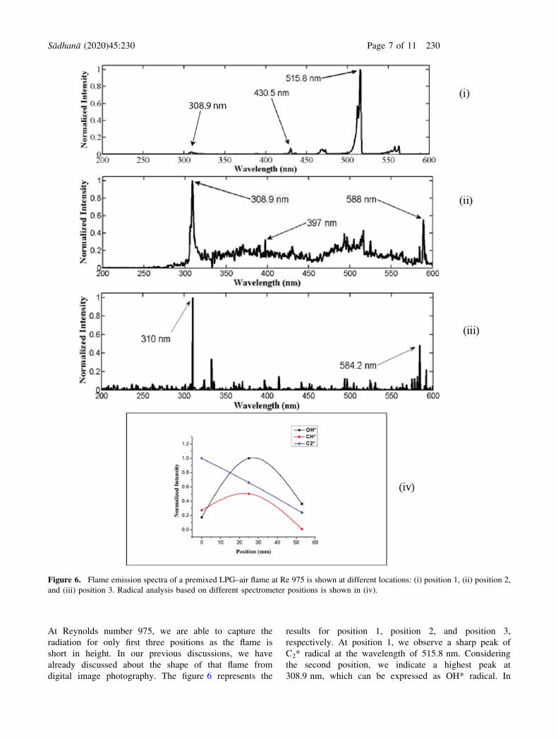
At Reynolds number 975, we are able to capture the
radiation for only first three positions as the flame is
short in height. In our previous discussions, we have
already discussed about the shape of that flame from
digital image photography. The figure 6 represents the
results for position 1, position 2, and position 3,
respectively. At position 1, we observe a sharp peak of
C2* radical at the wavelength of 515.8 nm. Considering
the second position, we indicate a highest peak at
308.9 nm, which can be expressed as OH* radical. In
Figure 6. Flame emission spectra of a premixed LPG–air flame at Re 975 is shown at different locations: (i) position 1, (ii) position 2,
and (iii) position 3. Radical analysis based on different spectrometer positions is shown in (iv).
Sådhanå (2020) 45:230 Page 7 of 11 230

Figure 7. Flame emission spectra of a premixed LPG–air flame at Re 1100 for (i) position 1, (ii) position 2, (iii) position 3, and (iv)
position 4. Radical analysis based on different spectrometer positions is elucidated in (v).
230 Page 8 of 11 Sådhanå (2020) 45:230
case of third position of the spectrometer, there is also
OH*, observed in dominating nature at 310 nm. So, in
our case, at Reynolds number around 975, there is a
maximum influence of OH* in the uppermost part of that
premixed flame while the lowermost part of the flame
has a great influence of C2*. The variation in the
intensity of the primary radicals, OH*, CH* and C2*
with respect to the location of the spectrometer is sum-
marized in figures 6iv. If we visualize that figure, we can
observe that there is a sharp peak of OH* present in the
positions 2 and 3, which is dominating the spectrum
regime of flame.
In the spectrum of the flame based on Reynolds
number 1100, we find the sharp peaks at 335, 360, 504,
524 and 584 nm at position 1 (figure 7i). At position 2,
OH* (corresponds to 308.9 nm) shows a peak. Another
peak at C2* region (515.8 nm) is observed (figure 7 ii).
We observe that the inner rich premixed flame shows
bluish green colour (figure 3ii). The existence of both
CH* (430.2 nm, responsible for blue colour) and C2*
(responsible for green colour) at position 2 corroborates
this observation. From the position 4 to position 5 (fig-
ure 7v), C2* dominates over other. However, there is a
prominent co-existence of OH* and C2* up to position 3
although we observe the dominance of C2* beyond
position 3. At position 4 and 5, due to the presence of
the soot (yellowish colour at the tip of the inner flame,
shown in figure 3 for Re 1100), we observe a prominent
spectral band from 500 nm to 650 nm (a part of this
band is shown in figure 7iv).
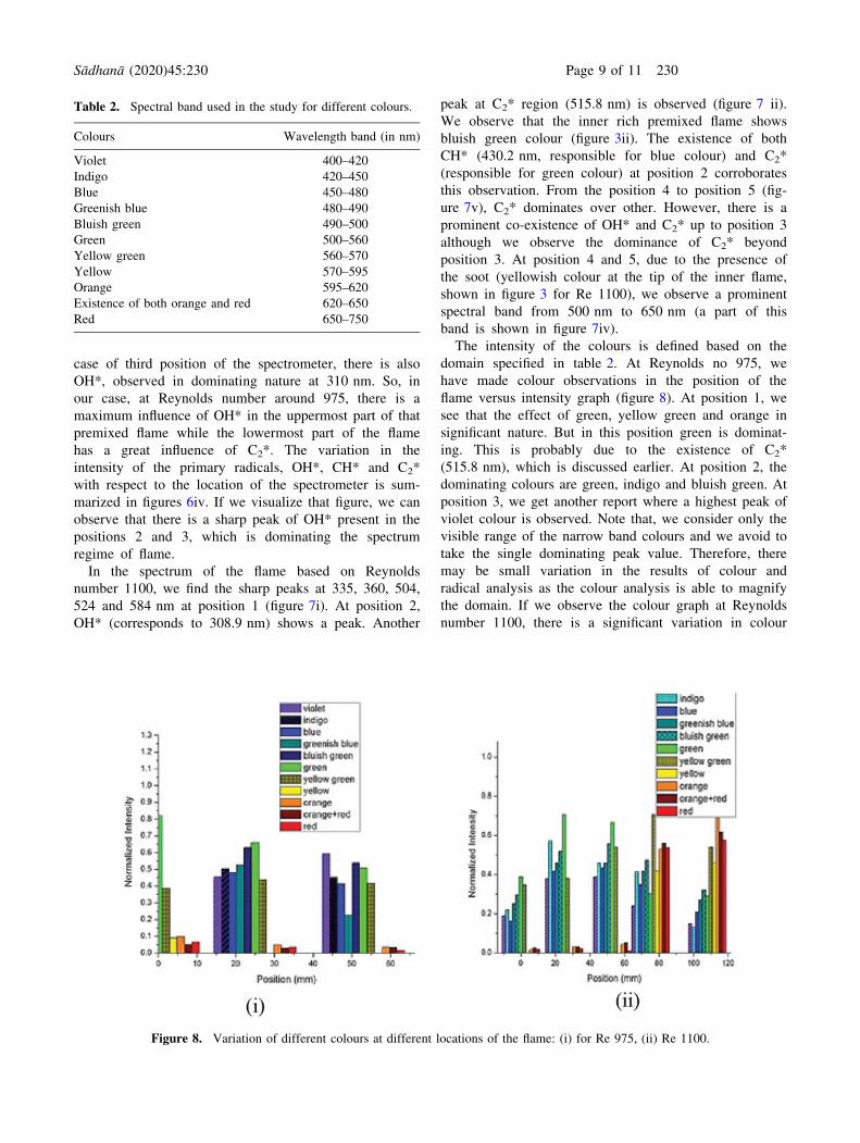
The intensity of the colours is defined based on the
domain specified in table 2. At Reynolds no 975, we
have made colour observations in the position of the
flame versus intensity graph (figure 8). At position 1, we
see that the effect of green, yellow green and orange in
significant nature. But in this position green is dominat-
ing. This is probably due to the existence of C2*
(515.8 nm), which is discussed earlier. At position 2, the
dominating colours are green, indigo and bluish green. At
position 3, we get another report where a highest peak of
violet colour is observed. Note that, we consider only the
visible range of the narrow band colours and we avoid to
take the single dominating peak value. Therefore, there
may be small variation in the results of colour and
radical analysis as the colour analysis is able to magnify
the domain. If we observe the colour graph at Reynolds
number 1100, there is a significant variation in colour
Table 2. Spectral band used in the study for different colours.
Colours Wavelength band (in nm)
Violet 400–420
Indigo 420–450
Blue 450–480
Greenish blue 480–490
Bluish green 490–500
Green 500–560
Yellow green 560–570
Yellow 570–595
Orange 595–620
Existence of both orange and red 620–650
Red 650–750
Figure 8. Variation of different colours at different locations of the flame: (i) for Re 975, (ii) Re 1100.
Sådhanå (2020) 45:230 Page 9 of 11 230

amplitudes of the flame. In position 1, blue and yellow
green are in dominating nature. In our study, from the
initial position to position 3, we see intensity of the
flame colours, which we have shown in position 1, is
gradually increased. But in 4 and 5 positions, red, orange
and yellow colours are observed. The yellow as well as
the reddish colour appear due to soot formation at the
highest position of that flame.
4. Conclusion
The visualization of a flame image, taken from high speed
camera, gives some useful meaning in order to differentiate
the flame colour structure and the behavior through naked
eyes. Apart from this, spectroscopic analysis using spec-
trometer gives another advantage compared to flame
imaging analysis. Spectrometer provides the different col-
ours, radicals (OH*, CH*, C2*) analysis of a wide range.
Through this study, we can summarize:
• At Re 975 to 1100, we find a ‘‘double flame
structure’’ in our premixed configuration of the co-
flow burner. Therefore, we concentrate on that region
using spectrometer. The co-existence of CH* and
C2* makes the bluish green colour of the inner rich
premixed flame.
• At lowReynoldsnumber (incaseofpremixedflame), at the
bottom segment of the flame (position 1, close to tip of the
inner tube), green colour dominates. On the other hand,
using radical analysis we find that there is an influence of
C2* at that position of the flame. The intensity of C2*
decreases and the intensity ofOH* increaseswith theflame
height.
• At high Reynolds number, due to the soot formation
yellow colour of the flame progressively increases
found from both radical and colour analysis.
• As we consider narrow region for different visible
colours, a colour based detail study is possible to
predict the behavior of a combustion process. This type
of flame monitoring analysis may be very helpful in the
fundamental study of different combustors.
Acknowledgement
This paper is a revised and expanded version of an article
entitled, ‘‘EXPERIMENTAL STUDY ON LPG–AIR
MIXED FLAME IN LAMINAR CO-FLOW BURNER’’,
Paper No., ‘‘57’’ presented in ‘‘First International Confer-
ence on Mechanical Engineering’’ held at ‘Jadavpur
University’, Kolkata, India during January 4–6, 2018.
NomenclatureRe Reynolds number
References
[1] Richards G A, McMillian M M, Gemmen R S, Rogers W A
and Cully S R 2001 Issues for low-emission, fuel-flexible
power systems. Progr. EnergyCombust. Sci. 27(2): 141–169[2] Martins C A, Pimenta A P, Carvalho Jr J A, Ferreira M A
and Caldeira-Pires A A 2005 CH and C2 radical character-
ization in natural gas turbulent diffusion flames. Mech. Sci.Eng. 27(2): 110–118
[3] De S, Bhattacharya A, Mondal S, Mukhopadhyay A and Sen
S 2018 Investigation of flame behavior and dynamics prior to
lean blowout in a combustor with varying mixedness of
reactants for the early detection of lean blowout. Int. J. SprayCombust. Dyn. 1756827718812519
[4] Gangopadhyay T, De S, Biswas A, Saha A, Mukhopadhyay
A and Sen S 2016 Recurrence Analysis of Dynamics of
Premixed and Partially Premixed Flames near Lean Blowout.
In: Conference on Nonlinear Systems and Dynamics IISERKolkata. 16: 18
[5] Gore J P and Zhan N J 1996 NOx emission and major
species concentrations in partially premixed laminar
methane/air coflow jet flames. Combust. Flame 105(3):
414–427
[6] Miller I M and Maahs H G 1977 High-pressure flame system
for pollution studies with results for methane–air diffusion
flames
[7] Lee K and Ryu J 2005 An experimental study of the flame
propagation and combustion characteristics of LPG fuel.
Fuel 84(9): 1116–1127[8] Sato Y 2000 Research Trend in Power System using
Alternative Fuels. IWPS2000. 27–30[9] Mishra D P and Rahman A 2003 An experimental study of
flammability limits of LPG/air mixtures. Fuel 82(7):
863–866
[10] Demirbas A 2002 Fuel properties of hydrogen, liquefied
petroleum gas (LPG) and compressed natural gas (CNG) for
transportation. Energy Sources 24(7): 601–610[11] Hossain A andNakamura Y 2014 A numerical study on the
ability to predict the heat release rate using CH* chemilu-
minescence in non-sooting counterflow diffusion flames.
Combustion and flame 161(1): 162–72
[12] Docquier N and Candel S 2002 Combustion control and
sensors: a review. Progr. Energy Combust. Sci. 28(2):
107–150
[13] Arias L, Torres S, Sbarbaro D and Farias O 2008 Photodi-
ode-based sensor for flame sensing and combustion-process
monitoring. Appl. Opt. 47(29): 5541–5549[14] Ballester J and Garcıa-Armingol T 2010 Diagnostic tech-
niques for the monitoring and control of practical flames.
Progr. Energy Combust. Sci. 36(4): 375–411
[15] Candel S 2002 Combustion dynamics and control: progress
and challenges. Proc. Combust. Inst. 29(1): 1–28[16] Samaniego J M and Mantel T 1999 Fundamental mecha-
nisms in premixed turbulent flame propagation via flame–
vortex interactions: Part I: Experiment. Combust. Flame118(4): 537–556
[17] Hardalupas Y and Orain M 2004 Local measurements of the
time-dependent heat release rate and equivalence ratio using
chemiluminescent emission from a flame. Combust. Flame139(3): 188–207
230 Page 10 of 11 Sådhanå (2020) 45:230

[18] De S, Sarkar S, Munshi J, Bhattacharya A, Mukhopadhyay A
and Sen S 2017 An experimental study on extinction and
stability of counter flow non-premixed flames. In: 25th
National Conference on Internal Combustion Engines andCombustion (NCICEC2017)
[19] Ballester J, Sanz A, Hernandez R and Smolarz A 2005
Detection and Analysis of Emitted Radiation for Advanced
Monitoring and Control of Combustors In: PhotonicsApplications in Industry and Research IV. 5948: 59482H
[20] Cheng T S, Wu C Y, Li Y H and Chao Y C 2006 Chemilumi-
nescence measurements of local equivalence ratio in a partially
premixed flame. Combust. Sci. Technol. 178: 1821–1841[21] Nori V N and Seitzman J M 2007 Chemiluminescence
measurements and modeling in Syngas, methane and Jet-A
fueled combustors. In: 45th AIAA Aerospace SciencesMeeting and Exhibit. 466
[22] Nori V N and Seitzman J M 2009 CH* chemiluminescence
modeling for combustion diagnostics. Proc. Combust. Inst.32(1): 895–903
[23] Docquier N, Lacas F and Candel S 2002 Closed-loop
equivalence ratio control of premixed combustors using
spectrally resolved chemiluminescence measurements. Proc.Combust. Inst. 29(1): 139–145
[24] Muruganandam T M, Kim B H, Morrell M R, Nori V N,
Patel M, Roming B W and Seitzman J M 2005 Optical
equivalence ratio sensors for gas turbine combustors. Proc.Combust. Inst. 30(1): 1601–1609
[25] Huang H W, Zhang Y 2011 Digital colour image processing-
based measurement of premixed CH4 ? air and C2H4 ? air
flame chemiluminescence. Fuel 90(1): 48–53[26] Krabicka J, Lu G and Yan Y 2011 Profiling and character-
ization of flame radicals by combining spectroscopic imag-
ing and neural network techniques. IEEE Trans. Instrum.Meas. 60(5): 1854–1860
[27] Wang Y, Makwana A, Iyer S, Linevsky M, Santoro R J,
Litzinger T A and O’Connor J 2018 Effect of fuel
composition on soot and aromatic species distributions in
laminar, co-flow flames. Part 1. Non-premixed fuel. Com-bust. Flame 189: 443–455
[28] Sahu K B, Kundu A, Ganguly R and Datta A 2009 Effects of
fuel type and equivalence ratios on the flickering of triple
flames. Combust. Flame 56(2): 484–493
Sådhanå (2020) 45:230 Page 11 of 11 230