characterization of thermally activated dislocation mechanisms using transient tests
TRANSCRIPT
Materials Science and Engineering A322 (2002) 118–125
Characterization of thermally activated dislocation mechanismsusing transient tests
J.L. Martin a,*, B. Lo Piccolo a, T. Kruml a, J. Bonneville b
a Departement de Physique, Ecole Polytechnique Federale, 1015- Lausanne, Switzerlandb Laboratoire de Physique Metallurgique, Uni�ersite de Poitiers, SP2MI, B.P. 179, F-86960- Futuroscope Cedex, France
Abstract
Two methods of repeated transient tests, namely relaxation and creep, are shown to be ideal techniques for the characterizationof plastic deformation processes. They yield similar information about a microscopic activation volume, which is the signature ofthe operating dislocation mobility mechanism. Microstructural parameters are also obtained, the values of which are different increep and stress relaxation. They characterize work-hardening during the transient and dislocation exhaustion rates respectively.The equations describing the transients and the assumptions involved are presented. Experimental results on Ni3Al polycrystalsillustrate the possibilities of both tests and support the above assumptions. In particular, crystals which work-harden exhibit highdislocation exhaustion-rates, as shown by comparison of Ni3Al with TiAl, Ge and Cu. The respective contributions to thestrain-rate of the mobile dislocation densities and velocities can also be estimated. © 2002 Elsevier Science B.V. All rightsreserved.
Keywords: Transient tests; Activation volume; Dislocation exhaustion; Mobile dislocations densities
www.elsevier.com/locate/msea
1. Introduction
Plastic deformation results from dislocation emissionat sources and their motion to locations in the crystalwhere they are held up or disappear. This can occur (i)by interaction with other dislocations or (ii) by escapeat the crystal surfaces or annihilation with dislocationsof opposite sign.
The Orowan equation expresses the plastic strain-rate�� p as proportional to the mobile dislocation density, �m,and their average velocity �,
�� p=��m�b (1)
where b is the Burgers vector and � a geometriccoefficient.
A constant strain-rate test neither allows a determi-nation of how many dislocations are moving in thesolid and at which velocity, nor yields informationabout dislocation multiplication and storage. However,transient mechanical tests can answer these questions.
Transient tests can be performed as follows: amonotonous deformation test at a given strain-rate andtemperature is interrupted at a selected stress and thespecimen is allowed to relax (or creep). The idea ofperforming a transient test is not new. In a stressrelaxation test (see a review by Dotsenko [1]), the totalstrain is kept constant and the stress is recorded as afunction of time. In a transient creep experiment, thestress is kept constant and the variation in strain ismeasured as a function of time. The deformationparameters can then be measured which are not directlyaccessible during monotonous loading. Provided thetransient is not too long, the corresponding dislocationmechanisms are not too different from those operatingat constant strain-rate and therefore useful informationcan be gained about them.
With the aim of separating the respective contribu-tions to the plastic strain-rate of mobile dislocationdensities and velocities, repeated transient mechanicaltests are being employed. They include repeated relax-ation tests and repeated creep experiments. The princi-ples of such transients are exposed together with theinterpretation of the materials behaviour and the re-lated assumptions. Recent results on Ni3Al polycrystals
* Corresponding author. Tel.: +41-21-6933371; fax: +41-21-6934470.
E-mail address: [email protected] (J.L. Martin).
0921-5093/02/$ - see front matter © 2002 Elsevier Science B.V. All rights reserved.PII: S0 9 21 -5093 (01 )01124 -8
J.L. Martin et al. / Materials Science and Engineering A322 (2002) 118–125 119
are presented to illustrate the possibilities of thesetechniques. In particular, the type of information whichcan be gained on �m and � will be shown, and thevalidity of our interpretation assessed.
2. Single transient tests
The phenomenological description of single tran-sients is first recalled, to introduce relations necessaryfor the description of repeated transients. Logarithmictransients are considered, i.e., stress (or strain) is alogarithmic function of time. This is usually the case atlow enough temperature, although a non-logarithmicbehaviour has been observed occasionally (see, for ex-ample, Bonneville et al. [2] in Ni3(Al, Ta) over a limitedtemperature range). As a rule, resolved shear-stressesand strains, � and �, respectively, will be considered.However, the relations below can apply to normalstresses and strains (respectively � and �) as well. Thesubscripts or superscripts r and c refer respectively tostress relaxation and creep conditions. A complete de-scription of relaxation tests can be found in [3] and ofcreep tests in [4].
For logarithmic stress relaxations [5], the stress de-creases by an amount �� as a function of time taccording to relation (2a):
��= − (kT/Vr) ln(1+ t/cr) (2a)
while for creep the plastic strain is:
��p= (kT/MVc) ln(1+ t/cc) (2b)
where M is the elastic modulus of the specimen ma-chine assembly, Vr and Vc have the dimension of avolume, cr and cc are time constants, k is the Boltzmannconstant and T the absolute temperature. A fit ofEquations (2) to the transient curve yields Vr and cr forstress relaxation, Vc and cc for creep. The time deriva-tive of (2) provides the plastic strain-rate for stressrelaxation and creep respectively:
�� p= (kT/MVr)[1/(cr+ t)] (3a)
�� p= (kT/MVc)[1/(cc+ t)] (3b)
Relation (3a) is obtained by considering the equationof the specimen-machine assembly: �=�/M+�p and itstime derivative under relaxation conditions: �� p= −�� .There are two ways of interpreting Eq. (2): either usingHart’s equation as suggested by Saada et al. [6] or inthe framework of thermally activated deformation asconsidered below.
Some assumptions are made for short transient tests:(i) the resolved shear stress � can be decomposed intoan internal stress, ��, and an effective stress, �*, i.e.�=��+�* [7], which yields for stress relaxation condi-tions: ���=K r��p. The specimen–machine assembly
equation under the same conditions gives ��p= −��/M, whence:
��*= (1+K r/M)�� (4a)
For creep:
−��*=���=K c��p (4b)
where �X (X=�*, ��, � or �p) is the variation ofparameter X during the transient, K r and K c are work-hardening coefficients. (ii) The dislocation velocity � isthermally activated:
�=d exp (−�G/kT) (5)
where �G is the activation energy of the mobilitymechanism, the vibration frequency of the averagedislocation segment and d the distance over which thissegment moves after a successful activation event. Theactivation volume V of the dislocation velocity isdefined as:
V= −��G/��*
V is obviously different from Vr and Vc in relations(2), and, therefore, cannot be determined via a singletransient experiment. During the short transient, pro-vided the change in effective stress ��* is small enoughand the pre-exponential factor in Eq. (5) is constant,the corresponding change in activation energy is−��*V. Under these conditions, the dislocation veloc-ity is:
�=�o exp(V��*/kT) (6)
after considering Eqs. (4a), (4b) and (5) and �o beingthe velocity at the onset of the transient (i.e. when��*=0). (iii) The mobile dislocation density is as-sumed to be a power function of the velocity, assuggested by a few experiments (see, for example [3]):
�m/�mo= (�/�o)� (7)
�mo being the mobile density at the onset of the tran-sient. The importance of variation of the mobile dislo-cation density during a stress relaxation test has beenemphasized long ago [8].
The exponent has different values r and c forrelaxation and creep, respectively. Comparing the ex-perimental strain-rate (3) and the value obtained via theOrowan relation (1) and using (6) and (7) yield:
(kT/MVr) [1/(cr+ t)]
=� �o�mo b exp[+ (V/kT)(1+r) (1+K r/M) �� ]
(kT/MVc) [1/(cc+ t)]
=� �o �mo b exp[− (V/kT) (1+c) K c��p]
for stress relaxation and creep, respectively.The above equation for stress relaxation can be
transformed by computing �� via relation (2a) andexpressing � �o �mo b using (1) and (3a) at t=0. Thisyields a relation between Vr and V :
J.L. Martin et al. / Materials Science and Engineering A322 (2002) 118–125120
Vr=�rV with �r= (1+r) (1+Kr/M). (8a)
The above equation for creep can be transformedsimilarly: ��p is expressed via relation (2b):
Vc=��cV with ��c= (1+c) (K c/M) (8b)
Vr and Vc are obtained from single transient experi-ments [relations (2)], while repeated transients are nec-essary to obtain V, as shown below. If Vr and V areknown, relation (8a) shows that information can begained about the structural parameters r and Kr. Thesame remark holds in creep for c and Kc.
3. Repeated transients
The technique of repeated stress relaxations althoughproposed long ago [9] has not been used extensively(see, for example, [10,11]). A new procedure has beendefined [12] in which the first stress relaxation starts atstress �M over a time interval ��, with a correspondingstress decrease ��1. The specimen is reloaded again upto �M, then allowed to relax by an amount ��2 during��, etc. (see a schematical representation of the test in[12]). At low enough temperatures, and for positivework-hardening coefficients, the following features areobserved: (i) ��j decreases as j, the relaxation number inthe series, increases. (ii) when the successive relaxationsare analyzed in terms of relation (2a), Vr is constantwhile the time constant cr,j depends on j.
The slowing down of the stress relaxations with j isdue to hardening which reduces �* despite a constantstress �M at the onset of each relaxation in a series. Thishardening is the result of dislocation exhaustion along atransient, so that the mobile dislocation density at thestart of each new relaxation step is lower as j increases.
Three methods are available to determine the volumeV. For various parameters below, the subscripts i and fwill be used, which refer to the onset and the end of arelaxation test in the series, respectively. The quasi-elas-tic reloading conditions ensure that no structuralchanges take place, i.e. �m and �� are the same at theend of relaxation No. j and at the onset of relaxationNo. ( j+1). Consequently, relations (1) and (6) yield:
�� i, j+1/�� f,j=�i, j+1/�f, j=exp(−V��j/kT). (9)
Relation (9) provides a first method of determiningV, by measuring the �� values as proportional to theslope of the relaxation curves. A second method con-sists in combining (2) and (9). This yields:
V= (kT/��j) ln(cr, j+�t
cr, j+1
) (10)
In this case, V is computed from the fitted parame-ters of (2a) for two successive relaxations in the series.
The comparison between successive stress relaxationscan be further developed, thus introducing a 3rdmethod based on the estimation of �r [relation (8a)]. Toexpress �r as a function of experimental data, the ratio�� i, j+1/�� i,j is computed following two different ways. Inthe first one, the strain-rates are compared at the onsetand the end of test No. j, using (3a) for t=0 andt=�t, respectively. This yields
�� ij/�� fj= (cr,j+�t)/cr,j=exp(− �rV��j/kT)��where relation (2a) has been used for test No. j, ��j
corresponding to �t. Combining this expression with(9) gives:
�� i, j+1/�� i,j=exp[(�r−1)V��j/kT] (11)
which provides a recurrent relation between �� in and �� i1(for a series of n relaxations)
�� i,n/�� i,1=exp[(�r−1)V �n−1
1
(��j/kT)]
The ratio �� i,n/�� i,1 can be replaced by cr,1/cr,n accordingto (3a) in which Vr is replaced by �rV, which yields:
�� i,n/�� i,1= [exp[(−�rV��n/kT)−1]
/[exp(−�rV��l/kT)−1].
Eliminating �� i, n/�� i, 1 between the two preceding relationsgives:
�r−1=1− (kT/(Vr �
n−1
1
��j))
ln[(exp(−Vr��n/kT)−1)
/(exp(−Vr��1/kT)−1)]. (12)
Relation (12) allows one to determine �r as a func-tion of experimental data such as Vr measured alongthe 1st relaxation and the ��j’s. Then V is obtained via(8a).
Depending on materials and deformation conditions,one of the three methods is used to determine V.However, the 3rd method is preferred since Vr and the��j’s are easily and safely measured.
A creep experiment, similar to the repeated stressrelaxation test, was proposed [13] and applied success-fully to � TiAl polycrystals at 300 K [14]. However,because of very low creep strains, it could not be usedin Cu or Ni3Al single crystals. Therefore, the repeatedcreep test is now performed along the following proce-dure (see Fig. 1): as the constant strain-rate test isinterrupted, the specimen is allowed to creep during �t(total creep strain ��1). It is then quasi-elasticallyreloaded by a small amount ��, then allowed to creepduring �t, under stress �M+�� (strain ��2), etc. Theinterpretation of the specimen behaviour is very close tothe one used above for successive stress relaxations.Similarly, three methods are available to determine V.In the present case, a relation equivalent to (9) is:

J.L. Martin et al. / Materials Science and Engineering A322 (2002) 118–125 121
�� i,j+1/�� f,j=�i, j+1/�f, j=exp (V��/kT)
=exp (VM��/kT) (13)
where �� is the strain increment during reloading whichcorresponds to ��. Relation (13) indicates in particularthat the above strain-rate or velocity ratios are indepen-dent of j, if the dislocation mobility mechanism [i.e. Vin relation (5)] is the same. Relation (13) provides a firstmethod of determining V, by measuring the �� values asthe slope of the creep curves, and deducing �� from ��.A second method provides a relation equivalent to (10):
V= (kT/��) ln�cc, j+�t
cc, j+1
.Vc,j
Vc, j+1
�. (14)
In this case, V is computed from the fitted parame-ters of (2) along two successive creep tests in the series(usually the 1st and 2nd ones). The comparison be-tween two successive creep tests can be pursued toestimate ��c [relation (8b)]. As above, the ratio �� i, j+1 /�� i,j is computed, using two different procedures, whichyields
�� i, j+1/�� i,j=exp((MVc,j/kT) (��/��c,j−��j))
which is equivalent to (11).The second way of computing the above strain-rate
ratio consists in using (3b):
�� i,j+1/�� i,j=Vc, j . cc, j/(Vc, j+1 . cc, j+1)
The ratio of the time constants is calculated byconsidering relation (2b) for t=�t for tests No. j andj+1 respectively:
�� i, j+1/�� ij= (Vc,j/Vc,j+1) [exp(MVc,j+1��j+1/kT) −1]
/[exp(MVc,j��j/kT)−1]
By eliminating �� i, j+1/�� i,j between this last relationand the first one, an expression is obtained whichcontains ��c, j and various parameters such as the Vc’sand the �� ’s, measured along two successive tests re-spectively No. j and j+1. Although this expression iscomplicated, the Vc’s and the �� ’s are determinedrather safely, so that this latter method has been usedmost of the time. ��c,j being known as well as Vc,j, V iscomputed with relation (8b).
4. Experimental
Compression testing is performed on a RMC 100Schenck machine under a He or Ar atmosphere. Aradiant heating furnace allows experiments betweenroom temperature and 1273 K. The temperature stabil-ity achieved during a mechanical test is �0.1 K. Thecross-section of the compression samples is of 3.5×3.5mm2 with a 7 mm length. Results of the technique ofrepeated creep transients are reported for Ni3Al poly-crystals and compared with those of successive stressrelaxations. More details can be found in [15]. Activa-tion volumes are expressed in units of b3, b being theBurgers vector of a superpartial dislocation in this L12
structure. In this case, the above conditions (logarith-mic transient tests, with a constant V) are fullfilled [15].
5. Results and discussion
The transition between monotonic and transient testsis first studied to verify the consistency of the abovedescription of the transients. A continuity of the plas-tic-strain rates, at the end of the monotonic test and atthe onset of the transient is expected, as suggested by
Fig. 1. Schematical representation of a repeated creep test.
Fig. 2. Stress–strain curve with a strain-rate jump (s.r.j.) in the circledregion. Ni74Al26 polycrystals. 300 K. Stress relaxations are performedalong the curve. �� p and �� po are respectively the plastic strain-rates justbefore and at the onset of relaxation.
J.L. Martin et al. / Materials Science and Engineering A322 (2002) 118–125122
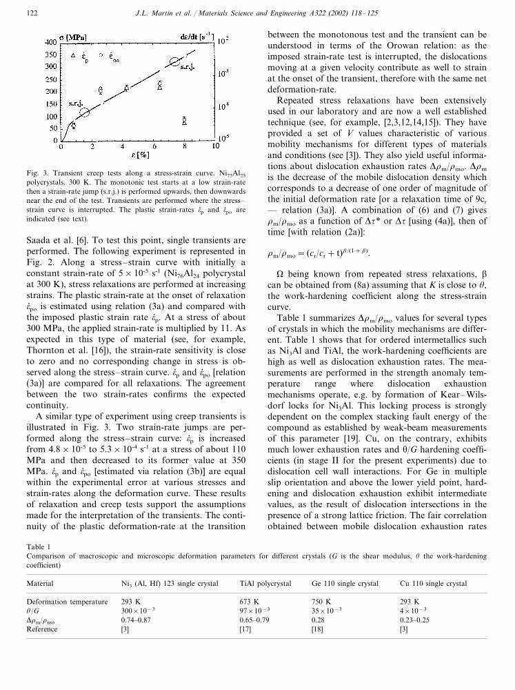
Fig. 3. Transient creep tests along a stress-strain curve. Ni75Al25
polycrystals. 300 K. The monotonic test starts at a low strain-ratethen a strain-rate jump (s.r.j.) is performed upwards, then downwardsnear the end of the test. Transients are performed where the stress–strain curve is interrupted. The plastic strain-rates �� p and �� po areindicated (see text).
between the monotonous test and the transient can beunderstood in terms of the Orowan relation: as theimposed strain-rate test is interrupted, the dislocationsmoving at a given velocity contribute as well to strainat the onset of the transient, therefore with the same netdeformation-rate.
Repeated stress relaxations have been extensivelyused in our laboratory and are now a well establishedtechnique (see, for example, [2,3,12,14,15]). They haveprovided a set of V values characteristic of variousmobility mechanisms for different types of materialsand conditions (see [3]). They also yield useful informa-tions about dislocation exhaustion rates ��m/�mo. ��m
is the decrease of the mobile dislocation density whichcorresponds to a decrease of one order of magnitude ofthe initial deformation rate [or a relaxation time of 9cr
— relation (3a)]. A combination of (6) and (7) gives�m/�mo as a function of ��* or �� [using (4a)], then oftime [with relation (2a)]:
�m/�mo= (cr/cr+ t)/(1+).
� being known from repeated stress relaxations, �can be obtained from (8a) assuming that K is close to �,the work-hardening coefficient along the stress-straincurve.
Table 1 summarizes ��m/�mo values for several typesof crystals in which the mobility mechanisms are differ-ent. Table 1 shows that for ordered intermetallics suchas Ni3Al and TiAl, the work-hardening coefficients arehigh as well as dislocation exhaustion rates. The mea-surements are performed in the strength anomaly tem-perature range where dislocation exhaustionmechanisms operate, e.g. by formation of Kear–Wils-dorf locks for Ni3Al. This locking process is stronglydependent on the complex stacking fault energy of thecompound as established by weak-beam measurementsof this parameter [19]. Cu, on the contrary, exhibitsmuch lower exhaustion rates and �/G hardening coeffi-cients (in stage II for the present experiments) due todislocation cell wall interactions. For Ge in multipleslip orientation and above the lower yield point, hard-ening and dislocation exhaustion exhibit intermediatevalues, as the result of dislocation intersections in thepresence of a strong lattice friction. The fair correlationobtained between mobile dislocation exhaustion rates
Saada et al. [6]. To test this point, single transients areperformed. The following experiment is represented inFig. 2. Along a stress–strain curve with initially aconstant strain-rate of 5×10⁻⁵ s-1 (Ni76Al24 polycrystalat 300 K), stress relaxations are performed at increasingstrains. The plastic strain-rate at the onset of relaxation�� po is estimated using relation (3a) and compared withthe imposed plastic strain rate �� p. At a stress of about300 MPa, the applied strain-rate is multiplied by 11. Asexpected in this type of material (see, for example,Thornton et al. [16]), the strain-rate sensitivity is closeto zero and no corresponding change in stress is ob-served along the stress–strain curve. �� p and �� po [relation(3a)] are compared for all relaxations. The agreementbetween the two strain-rates confirms the expectedcontinuity.
A similar type of experiment using creep transients isillustrated in Fig. 3. Two strain-rate jumps are per-formed along the stress–strain curve: �� p is increasedfrom 4.8×10⁻⁵ to 5.3×10⁻⁴ s-1 at a stress of about 110MPa and then decreased to its former value at 350MPa. �� p and �� po [estimated via relation (3b)] are equalwithin the experimental error at various stresses andstrain-rates along the deformation curve. These resultsof relaxation and creep tests support the assumptionsmade for the interpretation of the transients. The conti-nuity of the plastic deformation-rate at the transition
Table 1Comparison of macroscopic and microscopic deformation parameters for different crystals (G is the shear modulus, � the work-hardeningcoefficient)
Ni3 (Al, Hf) 123 single crystal TiAl polycrystal Ge 110 single crystal Cu 110 single crystalMaterial
293 KDeformation temperature 673 K 293 K750 K300×10−3�/G 4×10−335×10−397×10−3
0.74–0.87 0.65–0.79��m/�mo 0.28 0.23–0.25[3]Reference [17] [18] [3]
J.L. Martin et al. / Materials Science and Engineering A322 (2002) 118–125 123
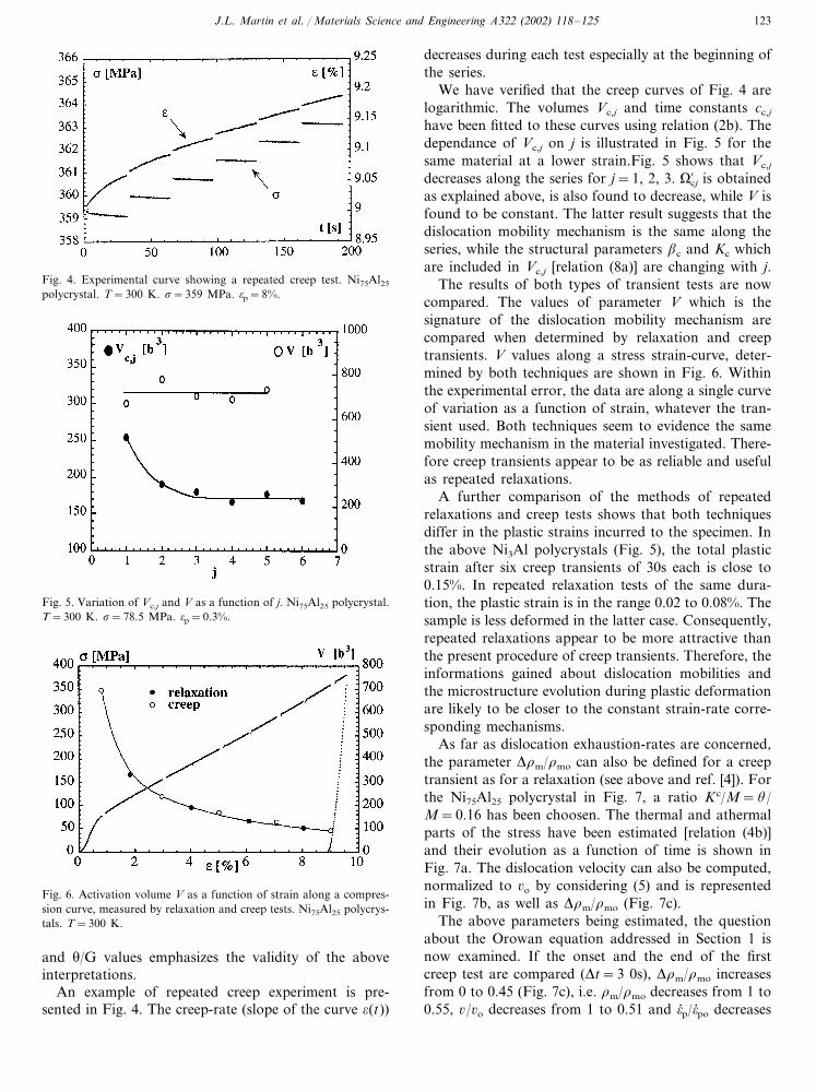
Fig. 4. Experimental curve showing a repeated creep test. Ni75Al25
polycrystal. T=300 K. �=359 MPa. �p=8%.
decreases during each test especially at the beginning ofthe series.
We have verified that the creep curves of Fig. 4 arelogarithmic. The volumes Vc,j and time constants cc,j
have been fitted to these curves using relation (2b). Thedependance of Vc,j on j is illustrated in Fig. 5 for thesame material at a lower strain.Fig. 5 shows that Vc,j
decreases along the series for j=1, 2, 3. ��cj is obtainedas explained above, is also found to decrease, while V isfound to be constant. The latter result suggests that thedislocation mobility mechanism is the same along theseries, while the structural parameters c and Kc whichare included in Vc,j [relation (8a)] are changing with j.
The results of both types of transient tests are nowcompared. The values of parameter V which is thesignature of the dislocation mobility mechanism arecompared when determined by relaxation and creeptransients. V values along a stress strain-curve, deter-mined by both techniques are shown in Fig. 6. Withinthe experimental error, the data are along a single curveof variation as a function of strain, whatever the tran-sient used. Both techniques seem to evidence the samemobility mechanism in the material investigated. There-fore creep transients appear to be as reliable and usefulas repeated relaxations.
A further comparison of the methods of repeatedrelaxations and creep tests shows that both techniquesdiffer in the plastic strains incurred to the specimen. Inthe above Ni3Al polycrystals (Fig. 5), the total plasticstrain after six creep transients of 30s each is close to0.15%. In repeated relaxation tests of the same dura-tion, the plastic strain is in the range 0.02 to 0.08%. Thesample is less deformed in the latter case. Consequently,repeated relaxations appear to be more attractive thanthe present procedure of creep transients. Therefore, theinformations gained about dislocation mobilities andthe microstructure evolution during plastic deformationare likely to be closer to the constant strain-rate corre-sponding mechanisms.
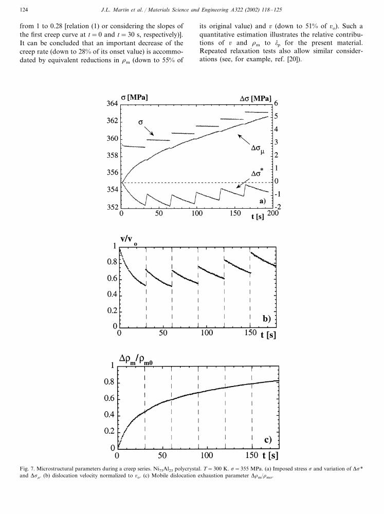
As far as dislocation exhaustion-rates are concerned,the parameter ��m/�mo can also be defined for a creeptransient as for a relaxation (see above and ref. [4]). Forthe Ni75Al25 polycrystal in Fig. 7, a ratio K c/M=�/M=0.16 has been choosen. The thermal and athermalparts of the stress have been estimated [relation (4b)]and their evolution as a function of time is shown inFig. 7a. The dislocation velocity can also be computed,normalized to �o by considering (5) and is representedin Fig. 7b, as well as ��m/�mo (Fig. 7c).
The above parameters being estimated, the questionabout the Orowan equation addressed in Section 1 isnow examined. If the onset and the end of the firstcreep test are compared (�t=3 0s), ��m/�mo increasesfrom 0 to 0.45 (Fig. 7c), i.e. �m/�mo decreases from 1 to0.55, �/�o decreases from 1 to 0.51 and �� p/�� po decreases
Fig. 5. Variation of Vc,j and V as a function of j. Ni75Al25 polycrystal.T=300 K. �=78.5 MPa. �p=0.3%.
Fig. 6. Activation volume V as a function of strain along a compres-sion curve, measured by relaxation and creep tests. Ni75Al25 polycrys-tals. T=300 K.
and �/G values emphasizes the validity of the aboveinterpretations.
An example of repeated creep experiment is pre-sented in Fig. 4. The creep-rate (slope of the curve �(t))
J.L. Martin et al. / Materials Science and Engineering A322 (2002) 118–125124
from 1 to 0.28 [relation (1) or considering the slopes ofthe first creep curve at t=0 and t=30 s, respectively)].It can be concluded that an important decrease of thecreep rate (down to 28% of its onset value) is accommo-dated by equivalent reductions in �m (down to 55% of
its original value) and � (down to 51% of �o). Such aquantitative estimation illustrates the relative contribu-tions of � and �m to �� p for the present material.Repeated relaxation tests also allow similar consider-ations (see, for example, ref. [20]).
Fig. 7. Microstructural parameters during a creep series. Ni75Al25 polycrystal. T=300 K. �=355 MPa. (a) Imposed stress � and variation of ��*and ���. (b) dislocation velocity normalized to �o. (c) Mobile dislocation exhaustion parameter ��m/�mo.
J.L. Martin et al. / Materials Science and Engineering A322 (2002) 118–125 125
6. Conclusions
The crystal response to successive relaxation testsand repeated creep transients has been presented inthe case of Ni3Al compounds. The equations describ-ing the deformation rates during the transients havebeen briefly described. It has been shown that bothtechniques yield comparable V values, this activationvolume being characteristic of dislocation mobilitywhich is therefore the same for both tests. It is differ-ent from the apparent volume Vr measured through asingle stress relaxation test. Vr expresses the wholeresponse of the crystal to a change in stress or strain-rate. It is related to the strain-rate sensitivity of thematerial. Useful information can also be obtainedabout structural parameters and K. describes thecoupling of the mobile dislocation density to theirvelocity and K the work-hardening coefficient duringthe transient. K and exhibit values which are differ-ent in creep and relaxation. A mobile dislocation ex-haustion parameter can be defined and estimated, andfound to depend on values. When different types ofcrystals and deformation conditions are compared,materials with a high work-hardening coefficient ex-hibit a high dislocation exhaustion during plastic de-formation. These transient tests also provide someinformation about the respective contribution of dis-location velocities and mobile densities to the plasticstrain-rate.
Acknowledgements
The authors are grateful to Dr A. Orlova and Pro-fessor G. Saada for positive suggestions during thisresearch. They acknowledge the financial support ofFonds National Suisse de la Recherche Scientifique.
They thank M. Bettinger for preparing themanuscript.
References
[1] V.I. Dotsenko, Phys. Stat. Sol. (b) 93 (1979) 11.[2] J. Bonneville, J.L. Martin, in: L.A. Johnson, D.P. Pope, J.O.
Stiegler (Eds.), Mat. Res. Soc. Symp. Proc. — High TemperatureOrdered Intermetallic Alloys IV, vol. 213, Materials ResearchSociety, Pittsburgh, PA, 1991, p. 629.
[3] J.L. Martin, B. Matterstock, P. Spatig, J. Bonneville, in: J.B.Bilde-Sørensen, J.V. Cartensen, N. Hansen, D. Juul Jensen, T.Leffers, W. Pantleon, O.B. Pedersen, G. Winther (Eds.), Proceed-ings of the 20th Risø Int. Symp. on Mater. Sc, Risø Nat. Lab,Roskilde, 1999, p. 103.
[4] B. Lo-Piccolo, J.L. Martin, J. Bonneville, in: S. Yue, E. Essadigi(Eds.), J.J. Jonas Symp. On Thermomechanical Processing ofSteel, Metallurgical Soc. of the Canadian Inst. of Mining, Metal-lurgy and Petroleum, Montreal, 2000, p. 183.
[5] F. Guiu, P.L. Pratt, Phys. Stat. Sol. 6 (1964) 111.[6] G. Saada, J. Bonneville, P. Spatig, Mater. Sc. Eng. A 234-236
(1997) 263.[7] A. Seeger, J. Diehl, S. Mader, H. Rebstock, Philos. Mag. 2 (1957)
323.[8] R.W. Rhode, T.V. Nordstrom, Scripta Metall. 7 (1973) 317.[9] G. Sargent, G. Jones, H. Conrad, Scripta Metall. 3 (1969) 481.
[10] L.P. Kubin, Phil. Mag. 30 (1974) 705.[11] P. Francois, D. Melot, J.M. Lefebvre, B. Escaig, J. Mater. Sci. 27
(1992) 2173.[12] P. Spatig, J. Bonneville, J.L. Martin, Mater. Sci. Eng. A 167
(1993) 73.[13] A. Orlova, J. Bonneville, P. Spatig, Mater. Sci. Eng. A191 (1995)
85.[14] J. Bonneville, B. Viguier, P. Spatig, Scripta Mater. 36 (1997) 275.[15] B. Lo Piccolo, Ph.D thesis 2044, Ecole Polytechnique Federale de
Lausanne, 1999.[16] P.H. Thornton, R.G. Davies, T.L. Johnston, Metall. Trans. 1
(1970) 207.[17] B. Viguier, J. Bonneville, J.L. Martin, Acta Mater. 44 (1996)
4403.[18] C. Charbonnier, Ph.D. research, to be published.[19] T. Kruml, J.L. Martin, J. Bonneville, Philos. Mag. A 80 (2000)
1545.[20] J.L. Martin, B. Lo Piccolo, J. Bonneville, Intermetallics 8 (2000)
1013.