characterizing the behavior of inconel clad a387 steel in ... · predict fatigue and fracture...
TRANSCRIPT
Characterizing the Behavior of Inconel Clad A387 Steel in High-Pressure High-
Temperature, Corrosive Environment
Bureau of Safety and Environmental Enforcement (BSEE)
Contract No. E15PC00010
Material Models for Fatigue and Fracture Properties of Inconel 625 Cladding – Final
Report
Prepared by
Michael L. Tims, Concurrent Technologies Corporation, 814-269-2515, [email protected] Ramgopal Thodla, DNV GL, 614-787-3268, [email protected]
Daniel B. George, Concurrent Technologies Corporation, 814-269-6426, [email protected] Juan J. Valencia, Concurrent Technologies Corporation, 814-269-2552, [email protected]
Brandon Gerst, DNV GL, 614-761-1214, [email protected]
Report Date
April 30, 2018
Submitted by
Concurrent Technologies Corporation (CTC) 100 CTC Drive
Johnstown, PA 15904

i
EXECUTIVE SUMMARY
The environment in which deep-water oil and gas exploration and extraction occurs is often both high pressure (15,000 psi or more) and high temperature (350 °F or higher) (HPHT). These conditions are often exacerbated by highly corrosive sour (or sweet) gas (with high concentrations of H2S and CO2) and high concentrations of chloride (Cl−). Components made of high-strength ferrous alloys are susceptible to hydrogen embrittlement and stress corrosion cracking under these conditions. To combat this problem, the industry uses corrosion-resistant alloys (including nickel-based Inconel1 alloys) weld cladded to the surfaces of ferrous components that come into contact with HPHT sour-gas conditions. While providing resistance to these conditions, the impact to fatigue and fracture of these cladding materials has not been well documented in the open literature. Therefore, the Bureau of Safety and Environmental Enforcement (BSEE) awarded a contract to Concurrent Technologies Corporation (CTC) to generate fatigue and fracture data for a common cladding used in deep-water oil and gas exploration and extraction equipment. Using specialized test equipment, DNV GL, a teammate on the effort, measured the following properties for the Inconel 625 cladding: fracture toughness, fatigue crack growth rate (FCGR) and cyclic fatigue under HPHT sour-gas conditions. Specifically, this team evaluated Inconel 625 cladding, which was welded to an ASTM A387 Grade 22, Class 2 steel substrate plate. As the clad test plate required two clad passes to achieve the minimum 0.25-inch clad thickness, and due to differences in dilution from the substrate plate in each of the clad layers, fracture toughness and FCGR were measured separately for both clad layers. Supporting the above-mentioned tests, slow-strain-rate (SSR) tensile, engineering stress-strain and bent-beam stress corrosion cracking (SCC) tests were also completed. This report summarizes the resulting properties from this assessment. In addition, mathematical models defining fatigue and FCGR were determined under three conditions: 1) best fit to measured data, 2) 97.5% confidence (i.e., statistical bound containing 97.5% of the population values based upon the experimental data) and 3) 99% confidence.
Salient conclusions from the work include the following.
The data and mathematical material models/equations provided in this report are a good start towards having a broad collection of publically available fatigue and fracture data for use by designers, failure analysts and regulatory bodies within the oil and gas exploration and extraction industry for clad components subjected to HPHT sour-gas conditions.
Fatigue and fracture differences were noted between the inner and outer layers of the two-layer weld cladding evaluated in the present project. Treating each clad layer as a “separate” material in fatigue and fracture assessments is justified.
No observable cracking or pitting was observed in any of the SCC specimens, which were subjected to the HPHT sour-gas environment for 30 days. A total of nine SCC specimens were tested: three replicates each tested at 95%, 110% and 120% of apparent yield load.
Slow strain rate tensile tests performed in the HPHT sour-gas environment did not show any evidence of environmentally assisted cracking. The fracture surface exhibited a ductile failure mode.
Fracture toughness tests performed in air and sour-gas environments in both the upper (low iron dilution) and lower (high iron dilution) Inconel 625 clad layers indicated the fracture toughness of
1 Inconel is a registered trademark of Special Metals Corporation, Huntington, WV.

ii
both clad layers is high. The fracture surfaces exhibited ductile features, suggesting that neither clad layers were susceptible to environmentally assisted fracture. The specimen from the lower clad layer (i.e., the one with greater dilution from the steel substrate) generally had higher initiation fracture toughness (threshold value of J > 240 N/mm, where J is fracture toughness) than did the specimens from the upper clad layer (threshold value of J ~190 N/mm). Plane-strain plastic-elastic fracture toughness (JIc, defined as the J value at a crack mouth opening displacement of 0.2 mm) averaged 257 N/mm for the upper clad layer; the singular JIc value for the lower clad layer was 344 N/mm.
FCGR frequency scan tests on both the upper (low iron [Fe] dilution) and lower (high Fe dilution) Inconel 625 clad layers did not exhibit a strong frequency dependence between 1 Hz and 3 mHz. However, between 1 mHz and 0.1 mHz, FCGR increased by about 100×. Although this suggests that chemical attack occurs at the crack tip, thereby making the material more susceptible to crack growth over time, effects of static growth rate, especially at the lowest test frequencies, may also have played a role in the increased FCGR at low test frequencies. During frequency scans, the lower layer (i.e., the one more highly diluted with substrate material) was found to have a higher FCGR by about an order of magnitude (i.e., 10×) over the upper layer. When the material was tested in the Paris law2 region, the FCGR of the lower layer was about twice that of the upper layer. These results suggest any crack that starts from the exterior of a cladded component may accelerate its growth rate once the outer clad layer has been completely penetrated and the crack grows into the lower clad layer.
To achieve failure within a few hundred to a few thousand cycles, cyclic fatigue specimens must be notched with a stress concentration factor of about 4.0 and subjected to nominal stresses that exceed yield. (For the Inconel 625 cladding evaluated here, the measured 0.2% offset yield strength at 350 °F was 65.9 ksi.) Fatigue failures occurred between 4000 to 10,000 cycles in the peak cyclic stress range of 60 to 88 ksi. The log-log relationship between the number of cycles to failure and peak cyclic stress followed a linear relationship with minimal scatter around the best-fit curve, which included peak cyclic stresses both below and above the Inconel 625 cladding yield strength.
While the HPHT sour-gas environment may lead to greater scatter (~5%) in tensile elongation, reduction of area and time to failure during slow-strain-rate testing, the mean values of these tensile properties were not significantly altered (< 1%) from values measured in air at 350 °F.
The cost of testing under HPHT sour-gas conditions limits the number of specimens that can be tested under a specified budget. In addition, the time to complete a single test under these conditions may take up to 8 weeks, which can place challenges on project scheduling. Fatigue testing under HPHT sour-gas conditions should begin as early as possible when testing any new material in future testing campaigns.
Fatigue and fatigue crack growth rate data can be fit to an exponential equation to mathematically define the associated behavior. Both a power law model and Walker equations are provided for FCGR. Due to the limited data (and the cost of generating the data), more sophisticated mathematical models, such as the NASGRO crack propagation model, could not be developed.
Methods for predicting lower/upper one-sided statistical bounds for these curves can be applied to predict fatigue and fracture behavior of Inconel 625 clad onto ASTM A387 Grade 22, Class 2 steel substrate under statistical confidence limits of 97.5% and 99%.
2 The Paris law region of a FCGR curve is the linear region of the log-log curve of crack growth rate versus the range of the stress intensity factor.

iii
Additive manufacturing methods were useful for providing material to the top of cladding without impairing its original microstructure/mechanical properties and enable physical completion of fracture and FCGR specimens.
The following recommendations are offered based upon the work.
Given the typical variability of weld cladding properties, additional testing is recommended to supplement those discussed here. Specimens from additional Inconel-625-clad test plates and additional clad vendors would help to further define the variability that could be expected among potential clad vendors and the normal variability expected from the weld cladding process itself.
Similarly, while cyclic fatigue testing was completed at a single stress ratio (R = 0.13), completing additional cyclic fatigue tests at other stress ratios (and possibly with other than sinusoidal stress versus time cycles) would provide the industry with additional valuable data.
Since other cladding alloys are either being used or are being considered for use by the oil and gas exploration and extraction industry, complementing the present work by assessing the fatigue and fracture behavior of these other materials would also benefit the industry.
To determine low-cycle stress-based fatigue curves for common cladding materials, the test should start with nominal peak cyclic stresses just above and just below the yield strength of the cladding.
The measured values and the mathematical models are useful for numerical simulations of fatigue and fracture. Specifically, designers can use the information to estimate the lifetime of components. Accident investigators can use the information to determine critical issues that led to failures. Regulatory bodies can use the information to evaluate the value of designs proposed for use in HPHT sour-gas conditions. The mathematical models were also summarized in a database, which is designed as a repository for the data generated in the current project as well as any data offered by the industry or developed in future efforts. Armed with these data, designers can use the information to estimate the lifetime of components. Accident investigators can use the information to determine critical issues that led to failures. Regulatory bodies can use the information to assess the value of designs proposed for use in HPHT sour-gas conditions.

iv
TABLE OF CONTENTS
EXECUTIVE SUMMARY .................................................................................................................... i
LIST OF TABLES ................................................................................................................................. v
LIST OF FIGURES ............................................................................................................................... v
LIST OF ACRONYMS, ABBREVIATIONS AND SYMBOLS...................................................... vii
1.0 INTRODUCTION...................................................................................................................... 1
2.0 PROJECT PARTICIPANTS .................................................................................................... 4
3.0 PRE-TESTED METALLURGICAL ANALYSIS .................................................................. 4
4.0 SUMMARY OF FATIGUE AND FRACTURE TESTING ................................................... 9
4.1 Engineering Stress-Strain Tensile Testing ............................................................................. 10 4.2 Slow-Strain-Rate Tensile Testing .......................................................................................... 11 4.3 Bent-Beam Stress Corrosion Cracking (SCC) Testing .......................................................... 12 4.4 Fracture Toughness ................................................................................................................ 13 4.5 Fatigue Testing....................................................................................................................... 17 4.6 Fatigue Crack Growth Rate (FCGR) ..................................................................................... 20
5.0 SPECIMEN PREPARATION ................................................................................................ 22
6.0 SUMMARY AND DISCUSSION OF RESULTS ................................................................. 24
6.1 Engineering Stress-Strain Tensile Testing ............................................................................. 24 6.2 Slow-Strain-Rate Tensile Testing .......................................................................................... 24 6.3 Bent Beam Stress Corrosion Cracking (SCC) Testing .......................................................... 27
6.4 Fracture Toughness Testing ................................................................................................... 29 6.5 Fatigue Testing....................................................................................................................... 32 6.6 Fatigue Crack Growth Rate (FCGR) Testing ........................................................................ 36
Paris Law FCGR Material Models ................................................................................................................................. 40 Walker Equation FCGR Material Model ....................................................................................................................... 41 Other Forms of FCGR Material Models ........................................................................................................................ 42
7.0 FATIGUE AND FRACTURE DATABASE .......................................................................... 43
8.0 CONCLUSIONS ...................................................................................................................... 43
9.0 RECOMMENDATIONS ......................................................................................................... 44
10.0 REFERENCES ......................................................................................................................... 45
APPENDIX A: RECOMMENDED TEST OUTLINE FOR MEASUREMENT OF FATIGUE
AND FRACTURE DATA UNDER HPHT SOUR-GAS CONDITIONS ....................................... 47

v
LIST OF TABLES
Page
Table 1: Chemistry and Strength of Substrate Materials ........................................................................ 2
Table 2: Chemical Composition of Inconel 625 [1] ............................................................................... 2
Table 3: Completed Mechanical Property Tests ..................................................................................... 3
Table 4: Sour Test Environment/Corrosion Specifications .................................................................... 4
Table 5: Physical Experimental Environmental Conditions ................................................................... 4
Table 6: Test Details for SSR Tensile Tests ......................................................................................... 11
Table 7: Details of Fracture Toughness Testing ................................................................................... 17
Table 8: Fatigue Test Plan .................................................................................................................... 20
Table 9: Details of Fatigue Crack Growth Rate Testing....................................................................... 21
Table 10: Fracture Toughness Results in HPHT Sour-Gas Environment ............................................ 30
Table 11: Fatigue Test Results .............................................................................................................. 33
Table 12: FCGR Results for the Lower Clad Layer ............................................................................. 38
Table 13: FCGR Results for the Upper Clad Layer .............................................................................. 39
LIST OF FIGURES
Page Figure 1: Cladded test plate used in current investigation ...................................................................... 2
Figure 2: Typical LOM microstructure at interface of clad layers ......................................................... 6
Figure 3: Typical SEM microstructure of the lower clad layer .............................................................. 6
Figure 4: Typical SEM microstructure of the upper clad layer .............................................................. 7
Figure 5: SEM-EDS elemental maps in the clad layers .......................................................................... 8
Figure 6: Iron dilution in the Inconel 625 cladding ................................................................................ 9
Figure 7: Illustration of test specimen orientations as extracted from clad plate ................................. 10
Figure 8: Engineering stress-strain specimen geometry ....................................................................... 10
Figure 9: Drawing of slow-strain-rate test specimen ............................................................................ 11
Figure 10: SSR curves for Inconel 625 cladding at room temperature ................................................. 12
Figure 11: SSR curves for Inconel 625 cladding at 350 °F .................................................................. 12
Figure 12: Four-point bent-beam SCC test specimen ........................................................................... 13
Figure 13: Fracture toughness and FCGR test specimens .................................................................... 14

vi
Figure 14: LOM macro and microstructures of the welded wrought Inconel 625 to the cladded steel plate using GMAW .............................................................................................................. 14
Figure 15: LOM macro and microstructures of the AM Inconel 625 added to the cladded steel plate 15
Figure 16: Fracture toughness test specimen drawing .......................................................................... 15
Figure 17: Macrostructural appearance of the clad layer weld beads ................................................... 16
Figure 18: Schematic representation of notch locations for FT and FCGR specimens ........................ 16
Figure 19: Drawing of axial fatigue test specimens.............................................................................. 18
Figure 20: Fatigue specimen notch resulting in a notch stress concentration factor of 4.0 [17] .......... 19
Figure 21: Drawing of compact tension FCGR specimen .................................................................... 21
Figure 22: LOM and SEM microstructures surrounding cladding-additive metal interface ................ 23
Figure 23: LOM microstructure of the upper clad layer before the deposition of the AM alloy ......... 23
Figure 24: Engineering stress-strain curve of Inconel 625 cladding at 350 °F ..................................... 24
Figure 25: Macrograph of tensile specimens tested at room temperature in sour-gas environment .... 25
Figure 26: Macrograph of tensile specimens tested at room temperature in air environment .............. 25
Figure 27: Macrograph of tensile specimens tested at 350 °F in sour-gas environment ...................... 26
Figure 28: Typical room-temperature microstructure of fracture surface in sour-gas environment .... 26
Figure 29: Typical 350 °F microstructure of fracture surface in sour-gas environment ...................... 26
Figure 30: Determination of displacements imparted to three sets of SCC specimens ........................ 27
Figure 31: Macrographs of specimens from four-point SCC bend tests for Inconel 625 cladding subjected to HPHT sour-gas conditions for 30 days ............................................................ 28
Figure 32: Exterior view of tensile surface from SCC four-point bend specimens for Inconel 625 cladding subjected to HPHT sour-gas conditions for 30 days ............................................. 29
Figure 33: Fracture toughness results ................................................................................................... 30
Figure 34: SEM image of fracture surface of upper clad layer fracture surface................................... 31
Figure 35: SEM image of fracture surface of lower clad layer fracture surface................................... 31
Figure 36: Curve fit to fatigue test results using pristine data for Inconel 625 cladding under HPHT sour-gas conditions .............................................................................................................. 34
Figure 37: Curve fit to fatigue test results using all data for Inconel 625 cladding under HPHT sour-gas conditions....................................................................................................................... 35
Figure 38: FCGR frequency scans of Inconel 625 cladding under HPHT sour-gas conditions ........... 37
Figure 39: Summary of FCGR for the lower clad layer under HPHT sour-gas conditions .................. 40
Figure 40: Summary of FCGR for the upper clad layer under HPHT sour-gas conditions .................. 40

vii
LIST OF ACRONYMS, ABBREVIATIONS AND SYMBOLS
Item Definition
a Crack Length Al Aluminum AM Additive Manufacturing ANSI American National Standards Institute API American Petroleum Institute
ASTM ASTM International (formerly known as American Society of Testing and Materials)
AYL Apparent Yield Load A387 ASTM A387 Grade 22, Class 2 a/W Crack Length to Specimen Width Ratio B Specimen Thickness b Linear Curve Fit Parameter (Intercept) BSEE Bureau of Safety and Environmental Enforcement C Carbon C Coefficient in Walker Equation Cl− Chloride CMOD Crack-Mouth Opening Displacement Co Cobalt CO2 Carbon Dioxide Cp Coefficient in Paris Law Cr Chromium CRA Corrosion Resistant Alloy CTC Concurrent Technologies Corporation C(T) Compact Tension da/dN Instantaneous Crack Growth Rate per Cycle da/dN|lower da/dN in the Lower Clad Layer
da/dN|lower,97.5% One-Sided Statistical Estimate of the Upper Value of the da/dN Population at 97.5% Confidence for the Lower Clad Layer
da/dN|lower,99% One-Sided Statistical Estimate of the Upper Value of the da/dN Population at 99% Confidence for the Lower Clad Layer
da/dN|upper da/dN in the Upper Clad Layer
da/dN|upper,97.5% One-Sided Statistical Estimate of the Upper Value of the da/dN Population at 97.5% Confidence for the Upper Clad Layer
da/dN|upper,99% One-Sided Statistical Estimate of the Upper Value of the da/dN Population at 99% Confidence for the Upper Clad Layer
DCPD Direct Current Potential Drop Dia Diameter DMM Digital Multimeter DNV DNV GL EDM Electrical Discharge Machining EDS Energy Dispersion Spectroscopy EL Elongation Env Environment, i.e., HPHT sour-gas conditions

viii
etc. Et Cetera, And So on e.g. Exempli gratia; for example f Frequency FAT Fatigue Test FCGR Fatigue Crack Growth Rate FE Finite Element Fe Iron FT Fracture Toughness GMAW Gas Metal Arc Welding h Hour Hi-Tech Hi-Tech Weld Overlay Group, LLC HPHT High Pressure High Temperature hr Hour Hz Hertz H2S Hydrogen Sulfide ID Identification in Inch Inc. Incorporated ISO The International Organization for Standardization i.e. Id Est; That Is J Fracture Toughness JIc Plastic-Elastic Fracture Toughness JMaxLoad Value of J at Maximum Load Jq Provisional Estimate for JIc Jth Threshold Fracture Toughness J0.2 mm Value of J at 0.2 mm CMOD J1.0 mm Value of J at 1.0 mm CMOD K Stress Intensity Factor K Thousands Kmax Maximum Stress Intensity Factor Kmin Minimum Stress Intensity Factor ksi Thousands of Pounds per Square Inch Kt Stress Concentration Factor l Liter LLC Limited Liability Company log Logarithm – Base 10 LOM Light Optical Microscopy m Linear Curve Fit Parameter (Slope) Max Maximum mg Milligram mHz Millihertz Min Minimum min Minute mm Millimeter MMPDS Metallic Materials Properties Development and Standardization Mn Manganese

ix
MO Missouri Mo Molybdenum MPa Millions of Pascals Msi Millions of Pounds per Square Inch N Newton N Number of Cycles N No, Specimen was Not Notched n Number of Samples
NACE NACE International (formerly known as the National Association of Corrosion Engineers)
Nb Niobium NC North Carolina Nf Number of Cycles to Failure
Nf,P% One-Sided Statistical Estimate for Number of Cycles to Failure at the Lower Bound of the Population with P% Confidence
Nf,97.5% One-Sided Statistical Estimate for Number of Cycles to Failure at the Lower Bound of the Population with 97.5% Confidence
Nf,99% One-Sided Statistical Estimate for Number of Cycles to Failure at the Lower Bound of the Population with 99% Confidence
Ni Nickel NJ New Jersey No. Number N/A Not Applicable OH Ohio P Phosphorus p First Exponential Term in Walker Equation PA Pennsylvania pCO2 Partial Pressure of CO2 PH Precipitation Hardened pH Potential Hydrogen pH2S Partial Pressure of H2S psi Pounds per Square Inch psia Pounds per Square Inch – Absolute PTFE Polytetrafluoroethylene q Second Exponential Term in Walker Equation R Radius R Crack Growth Resistance R Stress Ratio Ra Roughness Average of a Surface RA Reduction of Area Rmax Maximum Stress Ratio RT Room Temperature R.A. Reduction of Area S Peak Cyclic Stress S Sulphur s Second

x
ŝ Root Mean Square Error SCC Stress Corrosion Cracking sec Second SEM Scanning Electron Microscopy Si Silicon SQRT Square Root SSR Slow-Strain Rate t Student-t Value Ta Tantalum Ti Titanium TX Texas U.S. United States UNC Unified National Course Threads USA United States of America UTS Ultimate Tensile Strength W Specimen Width wt% Weight Percent WV West Virginia w/ With Y Yes, Specimen was Notched YS Yield Strength z Exponential Term in Paris Law °C Degrees Celsius °F Degrees Fahrenheit % Percent ″ Inch a Change in Crack Length K Change in Stress Intensity Factor max Maximum Stress during Cyclic Fatigue Testing min Minimum Stress during Cyclic Fatigue Testing in Microinch m Micron Approximately Less Than ≥ Greater Than or Equal to × Multiplied by ± Plus or Minus

1
1.0 INTRODUCTION
The environment in which deep-water oil and gas exploration and extraction occurs is often both high pressure (15,000 psi or more) and high temperature (350 °F or higher) (HPHT). These conditions are often exacerbated by highly corrosive sour (or sweet) gas (with high concentrations of H2S and CO2) and high concentrations of chloride (Cl−). Components made of high-strength ferrous alloys are susceptible to hydrogen embrittlement and stress corrosion cracking under these conditions. To combat this problem, the industry uses corrosion-resistant alloys (including nickel-based Inconel3 alloys) weld cladded to the surfaces of ferrous components that come into contact with HPHT sour-gas conditions. While providing resistance to these conditions, the impact to fatigue and fracture of these cladding materials has not been well documented in the open literature. Therefore, the Bureau of Safety and Environmental Enforcement (BSEE) awarded a contract to Concurrent Technologies Corporation (CTC) to generate fatigue and fracture data for a common cladding used in deep-water oil and gas exploration and extraction equipment.
The objective of the current work was to experimentally measure the following fatigue and fracture properties of nickel-based Inconel® 625 [1], which has been cladded to steel alloy ASTM International (ASTM) A387 Grade 22, Class 2 (A387) [2]4:
Stress corrosion cracking Fracture toughness Cyclic fatigue Fatigue crack growth rate.
In addition, fatigue and fracture material models (i.e., mathematical equations) suitable for numerical simulations were also desired. Such material models are often required for accurate hand calculations or numerical simulations of equipment to predict response during fatigue or fracture events.
Many failures in the oil and gas exploration and extraction industry occur at a relatively low number of fatigue cycles (several hundreds to a few thousands). In addition, the industry, when asked by the authors, indicated a greater interest in using fatigue data under stress conditions since a majority of components are designed based on stress rather than stain-based fatigue response [3]. Therefore, the present project focused on stress-based fatigue rather than strain-based fatigue measures even at the desired low-cycle count.
In the present work, Inconel 625 cladding was added to a 1-1/4-inch-thick ASTM A387 plate. The required minimum cladding thickness was 0.25 inch. To achieve the needed clad thickness, two separate clad layers were required. In this case, the application direction for both clad layers was identical. Figure 1 illustrates the clad plate from which specimens were taken. With the different level of dilution in each of the two clad layers, CTC, with concurrence from BSEE, agreed to treat each of the two layers as separate materials. Therefore, separate material properties were measured when specimen geometries permitted separate property measurements in each of the clad layers. After application of the cladding, the plate was heat treated to relieve
3 Inconel is a registered trademark of Special Metals Corporation, Huntington, WV. 4 This combination of materials is often used in the oil and gas exploration and extraction industry.

2
stress. The selected heat treatment is also commonly used for deep-water Inconel-625-cladded-steel exploration and extraction equipment.
Figure 1: Cladded test plate used in current investigation
The chemical composition and strength of the substrate plate are listed in Table 1, while the chemical composition of Inconel 625 is shown in Table 2. However, during application of a cladding, dilution of the substrate material into the cladding occurs due to melting of the top surface of the substrate, which mixes with the melted cladding materials prior to solidification. Dilution of the iron, and to a significantly lesser extent for other elements in the steel substrate, is highest in the first clad layer to be added. The amount of dilution in each additional clad layer is successively reduced. Since the fatigue and fracture of a metallic material is dependent upon its alloy composition, each of the first several clad layers may have different fatigue and fracture properties. Therefore, as much as the test sample geometries allow, separate properties were measured for each of the clad layers.
Table 1: Chemistry and Strength of Substrate Materials
High-
Strength
Steel
Alloy C Mn P S Si Cr Mo
Yield
Strength
(MPa)
Ultimate
Tensile
Strength
(MPa)
Elongation
(%)
Reduction
of Area
(%)
ASTM A387
0.05–0.15
0.30–0.60
0.025 Max
0.025 Max
0.50 Max
2.00–2.50
0.90–1.10 310 Min 515–690 18 Min 40 Min
ASTM A387
plate in present
analysis*
0.15 0.52 0.009 0.005 0.20 2.26 0.94 560 690 22.0 72.0
*Properties from plate certification. C = carbon; Mn = manganese; P = phosphorus; S = sulfur; Si = silicon; Cr = chromium; Mo = molybdenum; MPa = megapascal; Max = maximum; Min = minimum
Table 2: Chemical Composition of Inconel 625 [1]
Element Ni Cr Fe Mo Nb + Ta C Mn Si P S Al Ti Co
Weight percent
58.0 Min
20.0–23.0
5.0 Max
8.0–10.0
3.15–4.15
0.10 Max
0.50 Max
0.50 Max
0.015 Max
0.015 Max
0.40 Max
0.40 Max
1.0 Max
Nb = niobium; Ta = tantalum; Al = aluminum; Co = cobalt

3
The following properties were measured: stress-strain at a slow strain rate, cyclic fatigue, fracture toughness (FT), stress corrosion cracking (SCC) and fatigue crack growth rate (FCGR). To support these measurements, engineering stress-strain of the cladding was also measured in air at 350 °F. Several of the specimens were required to calibrate the equipment and/or to establish the test range used to measure many of the properties. Given their preexisting facility and experience in completing similar tests under the desired test environment, all HPHT sour-gas testing was completed at DNV GL (DNV) in Dublin, OH.
Table 3 shows the type and number of tests completed to determine the desired properties. The totals include calibration tests as well as tests from which fatigue and fracture data were measured. Table 3 also shows the ASTM standards associated with each of these property measurements.
Table 3: Completed Mechanical Property Tests
Mechanical
Property
ASTM
Method Rationale
Number of Test
Specimens Comments
Engineering Stress-Strain E21 [4]
Determine yield and ultimate tensile stresses
1 Required to determine stress levels for cyclic fatigue and other testing
Cyclic Fatigue E466 [5]
Generate S-Nf curves to evaluate fatigue performance
20
Establish complete specimen failure by cyclic fatigue; S = peak cyclic stress; Nf = number of cycles to failure
Fracture Toughness
E1820 [6]
Determine JIc fracture toughness values
7 Establishes dynamic fracture behavior; JIc = plastic-elastic fracture toughness
Fatigue Crack Growth Rate
E647 [7] Determine crack growth rates 10
Establishes crack growth rate resulting from loading on material with a given flaw
Slow Strain Rate Tensile G129 [8]
Evaluate the effects of HPHT sour-gas environment relative to testing in air
6 in target HPHT sour-gas
environment; 4 in air
Qualitatively measure rate of attack on cladding subjected to HPHT sour-gas environment
Stress Corrosion Cracking
G39 [9]
Qualitatively evaluate the effects of environment on crack propensity
9 Three replicates of each of three apparent yield load levels
Table 4 highlights several test conditions required by the American National Standards Institute (ANSI) and NACE International (NACE, formerly known as the National Association of Corrosion Engineers) standards related to testing in HPHT sour-gas environments. With the acknowledgement of BSEE, testing at HPHT conditions was completed under Level VI conditions as defined in ANSI/NACE MR0175/ISO 15156 [10]; the test conditions are

4
highlighted in Table 5. At DNV’s recommendation and with BSEE’s agreement, the potential hydrogen (pH) of the sour gas condition was 4–5; therefore, the aim pH was 4.5.
Table 4: Sour Test Environment/Corrosion Specifications
ANSI/NACE Method Title
ANSI/NACE MR0175/ISO 15156
Petroleum and Natural Gas Industries-Materials for Use in H2S Containing Environments in Oil and Gas Production; Part 1 General Principles for Selection of Cracking-Resistant Materials
ANSI/NACE TM0284 [11]
Evaluation of Pipeline and Pressure Vessel Steels for Resistance to Hydrogen-Induced Cracking
ANSI/NACE TM0177 [12]
Laboratory Testing of Metals for Resistance to Sulfide Stress Cracking and Stress Corrosion Cracking in H2S Environments
Rationale for use of test methods: these methods are used in conjunction with the standard ASTM test methods as guidelines for testing in a sour-gas (H2S) environment under HPHT conditions.
Table 5: Physical Experimental Environmental Conditions
Condition Value
Temperature (°F/°C) 350/177 Pressure (psi/bar) 1150/78 Hydrogen Sulfide, H2S (partial pressure, psi) 500 Chloride, Cl− (mg/l [minimum]) 150,000 Carbon Dioxide, CO2 (partial pressure, psi) 500 pH 4–5
2.0 PROJECT PARTICIPANTS
The project was funded and overseen by BSEE, who offered excellent technical direction and accountability. Based upon an open solicitation, DNV of Dublin, OH was selected as the test vendor to complete tests under HPHT sour-gas conditions. CTC machined the test specimens. DNV and CTC completed selected metallurgical analyses. CTC completed development of material models and a database of results.
3.0 PRE-TESTED METALLURGICAL ANALYSIS
CTC completed several metallurgical analyses of pre-tested Inconel 625 clad on the ASTM A387 steel substrate. Metallographic prepared samples taken from the cladded steel were analyzed using light optical microscopy (LOM) and scanning electron microscopy coupled with energy dispersion spectroscopy (SEM-EDS). SEM-EDS microscopy was primarily used to evaluate the effects of iron dilution throughout the Inconel 625 clad layers. These analyses demonstrated the following (as shown in Figures 2 through 4).
A good bond existed between the cladding and the steel substrate. Epitaxial crystal growth of the weld layers was observed. Neither coarse porosity, inclusions, nor cracks were observed in the Inconel 625
cladding.

5
Relatively coarse and directionally aligned primary dendrites5 were observed at the steel/overlay weld and overlay/overlay welds interfaces.
Most of the dendritic microstructure away from the interface had small secondary arm spacing.
The microstructural characteristics of the outer clad layer were found to be very similar to that of the inner clad layer: primary coarse dendritic columnar crystals that grew from the interface of preexisting material and much finer dendrites above the coarser ones.
Microsegregation was more pronounced at the coarser dendrites; the interdendritic segregation was presumably very fine delta and Laves phases common to nickel-based alloys [13].
Iron dilution fades as the distance from the steel interface increases; presumably iron is carried away from the interface by convection currents produced by the welding process. Figure 5(a) shows an example of the composition map of iron in the cladded layers.
The elemental map (Figure 5(b)) shows high concentration of niobium (Nb) and molybdenum (Mo) at the interface with the steel substrate, which indicates there is more microsegregation towards this region of the weld; this also indicates the presence of Laves phases is more prominent in this region of the weld; chromium (Cr) is uniformly distributed in the microstructure.
The iron content, as determined by SEM-EDS elemental iron analysis, decreases from approximately 26 weight percent (wt%) at the steel interface to approximately 8.5 wt%, at approximately 2500 microns (0.0985 inch) into the first weld layer (see Figure 6). The iron (Fe) content practically remains constant into the second layer, but decreases towards the interface with the additively manufactured material. The additively manufactured material layer is discussed below.
5 Dendrites are tree-like crystals that grow in solidifying metallic structures and typically result in anisotropic properties in the solidified mass.

6
Figure 2: Typical LOM microstructure at interface of clad layers
Figure 3: Typical SEM microstructure of the lower clad layer

7
Figure 4: Typical SEM microstructure of the upper clad layer

8
(a) Iron distribution
(b) Niobium, molybdenum and chromium distributions
Figure 5: SEM-EDS elemental maps in the clad layers

9
Figure 6: Iron dilution in the Inconel 625 cladding
4.0 SUMMARY OF FATIGUE AND FRACTURE TESTING
As also defined in the project interim report [14] the following section outlines the test methods and results. Specimens were extracted from the clad plate as illustrated in Figure 7.

10
Figure 7: Illustration of test specimen orientations as extracted from clad plate
4.1 Engineering Stress-Strain Tensile Testing
Stress levels used in many of the subsequent fatigue and fracture tests relied on measured yield strength (YS) and ultimate tensile strength (UTS) at 350 °F. Accordingly, one specimen conforming to ASTM E21 [4], and depicted in Figure 8, was tested in air. The specimen was taken so that its axis was perpendicular to the direction of individual clad passes as noted in Figure 7. This orientation ensured the specimens included the mixed microstructure associated with several weld beads. This orientation is typically the weakest direction in a weldment, including weld cladding. For these specimens, material in the gage length was a mixture of both upper and lower clad layers. The center gage area consisted of clad material, while substrate material was permitted in the threaded section, if needed to achieve a complete specimen.
Figure 8: Engineering stress-strain specimen geometry

11
4.2 Slow-Strain-Rate Tensile Testing
SCC susceptibility performance of the material was evaluated using two methodologies: slow-strain-rate tensile testing and bent-beam SCC, as described below. The SCC susceptibility performance of the material was evaluated in accordance with ASTM G129 [8]. Slow-strain-rate (SSR) tensile testing is a standard material test method in which specimens are subjected to elongation at a constant engineering strain rate of 4×10⁻⁶/sec. The load was varied to maintain the constant engineering strain rate. This test qualitatively gauges the effects of local environmental conditions on SCC behavior, material fracture susceptibility or SCC susceptibility. Standard tensile type specimens per ASTM G129 (round 0.150-inch diameter, 1.0-inch gage length, see Figure 9) were utilized for testing and sectioned from the cladded plate as illustrated in Figure 7. Specimens only included clad metal. The gage length of the specimens included material from both clad layers. Testing was performed at both ambient conditions and the temperature, pressure and environment defined in Table 5. The change in tensile properties between in-air and tests under HPHT sour-gas environment was used to qualitatively determine environmental effects. Table 6 shows the test conditions under which slow-strain rate tests were completed, while Figures 10 and 11 summarize the SSR results at room temperature and 350 °F, respectively. In this case, the SSR tensile response for both air and HPHT sour-gas conditions were similar indicating the cladding tensile response was not significantly impacted by the presence of the HPHT sour-gas environment.
Figure 9: Drawing of slow-strain-rate test specimen
Table 6: Test Details for SSR Tensile Tests
Test Conditions
Number of
Specimens
Air environment; room temperature 2 Air environment; 350 °F 2 Sour-gas environment; room temperature; high pressure 3 Sour-gas environment; 350 °F; high pressure 3

12
Figure 10: SSR curves for Inconel 625 cladding at room temperature
Figure 11: SSR curves for Inconel 625 cladding at 350 °F
4.3 Bent-Beam Stress Corrosion Cracking (SCC) Testing
Additionally, a semi-qualitative evaluation of the cladding’s ability to resist SCC was evaluated using a bent-beam test specimen as illustrated in Figure 12. The SCC susceptibility performance of the material was evaluated in accordance with ASTM G39 [9]. Specimens were ground to a

13
surface roughness not exceeding 30 in Ra. Standard four-point, all-clad metal bend specimens, 2 inches × 0.400 inch × 0.125 inch were tested concurrently using stress values based on the slow-strain-rate test results discussed above. Stress levels were based on a percentage of the apparent yield load during bending in the test clamp. All SCC tests were completed in HPHT sour-gas conditions defined in Table 5. The peak load applied to the specimens was 95%, 110% or 120% of apparent yield load. Three replicates were tested under each of the applied load values; specimens were held for 30 days in the HPHT environment.
Figure 12: Four-point bent-beam SCC test specimen
4.4 Fracture Toughness
The fracture toughness (FT) performance of the material was evaluated in accordance with ASTM E1820 [6]. Fracture toughness describes the ability of a material containing a crack to continue to absorb and dissipate energy by crack growth, but resist fracture. In this case, the plastic-elastic fracture toughness, denoted by JIc, was measured and represents the energy required to grow a thin crack. Fracture toughness is a quantitative way of conveying a material’s resistance to fracture when a crack is present. If a material has high fracture toughness, it will probably undergo ductile fracture. Standard compact tension specimens, C(T) [specimen thickness, B = 0.5 inch; specimen width, W = 1.0 inch], were utilized for testing. Test specimens were sectioned from the cladded plate as illustrated in Figures 7 and 13. Typically, the specimens for fracture toughness are removed from the parent material such that the entire specimen is of the parent material. However, two factors did not allow single-material specimens to be used for testing of the cladding. First, the two-layer cladding, where the fracture toughness was measured, was only 0.25 inch thick. The crack, illustrated at the base of the machined notch in Figure 12, must remain in the desired clad layer to test material in that layer. Steel from the substrate was needed to complete the physical test specimens below the substrate. Secondly, no material was initially available to complete the physical test specimens above the crack, i.e., the portion of the specimen that includes the pin loading holes used to apply the load. Initially, in order to complete the upper portion of test specimens, wrought Inconel 625 was welded to the cladded layer using gas metal arc welding (GMAW). However, the heat generated by the weld process produced a profound change in the microstructure and chemical distribution of the cladded layers (Figure 14). Therefore, this approach was discarded from further consideration as a method for the pin-loading-hole region of FT specimens. Instead, Inconel 625 was added to the top of the cladding by additive manufacturing (AM) using an SLM 280HL laser-powder bed fusion AM machine at CTC. Using this AM approach provided a very shallow

14
melting effect on the surface of the clad layer with practically no change in the microstructure of nearby cladded Inconel 625 material. This is shown in Figure 15. After adding the material, the resulting multi-material specimen was machined to dimensions consistent with ASTM E1820 as depicted in Figure 16. During testing in the HPHT sour-gas environment, the steel substrate was protected from reacting with the environment using a proprietary method developed by DNV.
Figure 13: Fracture toughness and FCGR test specimens
Figure 14: LOM macro and microstructures of the welded wrought Inconel 625 to the
cladded steel plate using GMAW

15
Figure 15: LOM macro and microstructures of the AM Inconel 625 added to the cladded
steel plate
Figure 16: Fracture toughness test specimen drawing
The weakest material was assumed to lie at the boundaries between the individual clad passes. Therefore, specimens were machined, ground and slightly macro-etched to reveal the boundaries of the clad passes as shown in Figure 17. This allowed the machinist to accurately align the

16
specimen notches with the edge of a clad pass as illustrated in Figure 18. Fracture toughness testing was performed either at 350 °F in air (to calibrate the test method) or at the temperature, pressure and environment defined in Table 5. Table 7 lists the final test conditions tested.
Figure 17: Macrostructural appearance of the clad layer weld beads
Figure 18: Schematic representation of notch locations for FT and FCGR specimens

17
Table 7: Details of Fracture Toughness Testing
Test Method
Notch Location
(Layer)
K-Rate*
(N·mm−3/2
/sec)
Number
of Tests Notes
DCPD (Calibration) Lower N/A 1 350 °F in air DCPD (Calibration) Upper N/A 1 350 °F in air Slow Rising Displacement Upper 0.085 1 HPHT sour-gas Slow Rising Displacement Upper 0.016 1 HPHT sour-gas Slow Rising Displacement Upper 0.0037 1 HPHT sour-gas Slow Rising Displacement Lower 0.005 1 HPHT sour-gas Slow Rising Displacement Upper 0.005 1 HPHT sour-gas DCPD = direct current potential drop *Values were selected after completion of first round of slow-rising displacement tests. K-rate values were the highest value (among 0.085, 0.016 and 0.0037 N·mm−3/2/sec) leading to consistent behavior with lower K-rate values. Notch locations for the last two slow-rising displacement tests were used to supplement those from the first set of three slow-rising displacement tests. They were tested at the layer having the lowest fracture toughness from the initial slow-rising displacement tests. K-rate is the time rate of change of applying the stress intensity factor.
In order to characterize the entire J-R curve (i.e., the curve of crack growth resistance, R, relative to J, the material’s fracture toughness) it was important to be able to measure the crack length in-situ using direct current potential drop (DCPD). However, in order to accurately characterize the crack length using this method in a multilayer system as illustrated in Figure 13, it was essential that a calibration curve be developed prior to making fracture toughness measurements. The calibration curve was developed using two tests in-air at 350 °F, one in each of the clad layers to develop a co-relation between the potential drop signals and the crack length (a). The pre-cracks for these calibration tests were located at a crack length to specimen width ratio (a/W) of 0.5,6 which was similar to the a/W value of 0.5 proposed for the environmental tests.
Fatigue and fracture toughness measurements were performed on servo electric frames, and the crack growth was measured using the DCPD technique. A constant current of 4.0 amps was applied across the crack mouth and the voltage drop across the crack mouth was measured using a high resolution digital multimeter (DMM). Platinum wires of 40-mil diameter were used for voltage and current probes. The platinum wires were heat shrunk in polytetrafluoroethylene (PTFE) to prevent contact with the cell and the solution. The spot weld locations of the probes on the samples were protected with a coating from Epoxy Systems™ Product 641 to prevent corrosion around the probes. The measured voltage drop was converted into crack length using the Johnson equation [15]. The crack mouth opening displacement (CMOD) measurements were performed using a load line correction.
4.5 Fatigue Testing
Fatigue is defined as the weakening of a material caused by cyclically applying stress, typically below the yield strength of the test material. However, to achieve the desired number of cycles to failure, several fatigue tests were completed with a peak cyclic stress above the yield strength, but below the UTS, of the cladding.
6 The a/W ratio for fracture toughness specimens is independent of the value used or required for fatigue crack growth rate testing discussed below.

18
The fatigue performance of the cladded material was characterized by S-Nf (S = peak cyclic stress; Nf = number of cycles to failure) fatigue curves. In high-cycle fatigue conditions, material performance is commonly characterized by an S-Nf curve. Given the desire of BSEE to include low-cycle fatigue (of the order of several hundred to a few thousand cycles), and with the overwhelming stress-based fatigue design criterion used by the oil and gas industry (as opposed to a strain-related design criterion) [3], all fatigue testing was completed in stress-controlled conditions. Therefore, significant scatter in the fatigue data was anticipated for the cladding, which is a welded material. Much of the anticipated scatter is due to the mixed microstructures common to welded material and discussed in Section 3.0 Pre-Tested Metallurgical Analysis.
Sinusoidal stress loading was applied during fatigue testing. Testing was performed in accordance with ASTM E466 [5] using an axially loaded test specimen in stress control at a test frequency (f) not greater than 0.3 Hz.7 Standard axial fatigue coupons (round 0.150-inch diameter, 1.0-inch gage length, see Figure 19) were utilized for testing and were excised from the cladded plate as illustrated in Figure 7.
Figure 19: Drawing of axial fatigue test specimens
Testing was performed at the temperature, pressure and environment defined in Table 5. Cyclic loading was completed at a stress ratio (R, minimum stress [min] divided by the maximum stress [max]) of 0.13. A single stress ratio was selected due to the limited number of fatigue specimens tested and the wide scatter expected in the results.8 As a result of achieving significantly greater numbers of cycles to failure in early fatigue tests, the subsequent specimens were notched via machining in a lathe. The associated stress concentration factor (Kt) for this notch design was originally 3.0, but to increase the local stress concentration and thereby further reduce the number of cycles to failure, it was changed to a geometry yielding a Kt value of 4.0 for the remaining specimens. Figure 20 shows the dimensions of the notch, which was centered along the length of the gage area as noted in Figure 19. Therefore, for any nominal stress (defined as 7 The maximum frequency of 0.3 Hz is a specified condition defined in American Petroleum Institute (API) 17TR8 [16]. 8 More measurements under a given stress ratio increases the reliability of the resulting data trends and the associated mathematical material models.

19
the tensile load divided by the cross-sectional area of the specimen at the base of the notch) greater than 25% of yield strength, the material at the base of the notch was stressed beyond the yield point of the pre-tested material.
Figure 20: Fatigue specimen notch resulting in a notch stress concentration factor of 4.0
[17]
The actual stress levels of the specimens in the HPHT sour-gas environment evolved as the fatigue data were being generated. This evolution was aided through low-cost (relative to testing in HPHT sour-gas conditions) testing in air at 2 Hz. From those early in-air fatigue tests, it became apparent that notched specimens were required to meet the desired cycle count of several hundreds to a few thousands. To achieve the desired cycle count, it became apparent that nominal stresses approaching yield strength (YS) of the Inconel 625 cladding were needed. These first several specimens tested at HPHT sour-gas conditions, however, did not fail until after several tens of thousands or even several hundred thousand cycles. Therefore, the peak cyclic stress for subsequent specimens was increased. Eventually, fatigue tests were conducted with peak stresses above YS, which is not unprecedented for Inconel 625 [18, 19]. The peak stress condition applied during successive fatigue tests continued to increase until the total number of desired fatigue tests was completed. The resulting test conditions shown in Table 8 were thereby established.

20
Table 8: Fatigue Test Plan
Environment
Temperature
(˚F)
Specimen
ID Notched R
σmax
(ksi)
f
(Hz)
Air 350 FAT-30 Y 0.13 60 2 Air 350 FAT-9 N 0.13 60 2 Air 350 FAT-32 N/Y 0.13 60 2 Air 350 FAT-35 Y 0.13 60 2 Air 350 FAT-13 Y 0.13 52 2 Air 350 FAT-16 Y 0.13 63.7 2 Air 350 FAT-3 Y 0.30 60 2 Air 350 FAT-33 Y 0.30 60 2 Air 350 FAT-31 Y 0.75 60 2
Sour-Gas 350 FAT-7 Y 0.13 52 0.3 Sour-Gas 350 FAT-7 Y 0.13 72 0.3 Sour-Gas 350 FAT-11 Y 0.13 60 0.3 Sour-Gas 350 FAT-8 Y 0.13 60 0.1 Sour-Gas 350 FAT-10 Y 0.13 60 0.1 Sour-Gas 350 FAT-2 Y 0.13 63.7 0.3 Sour-Gas 350 FAT-15 Y 0.13 63.7 0.3 Sour-Gas 350 FAT-15 Y 0.13 68 0.3 Sour-Gas 350 FAT-14 Y 0.13 70 0.3 Sour-Gas 350 FAT-36 Y 0.13 75 0.3 Sour-Gas 350 FAT-17 Y 0.13 85 0.3 Sour-Gas 350 FAT-4 Y 0.13 85 0.3 Sour-Gas 350 FAT-34 Y 0.13 88 0.3
Specimens FAT-7 and FAT-15 were initially tested at the lower of the two listed stress conditions without failure after a large number of cycles. The stress level was then increased and fatigue testing was continued. Y = yes; N = no
4.6 Fatigue Crack Growth Rate (FCGR)
The FCGR performance of the material was evaluated in accordance with ASTM E647 [7]. FCGR testing, also known as da/dN testing, is a method of evaluating the ability of a material to grow a crack and then quantifying the rate of the crack growth, where a = crack length, N = number of cycles and da/dN = the instantaneous crack growth rate. Unlike fatigue testing where the specimens are initially crack free, FCGR evaluates the safety and reliability of materials by subjecting the specimen to repeated loading and unloading in the presence of a preexisting crack. The FCGR test reports the resistance to stabilized crack extension under cyclic loading. The Paris law9 region was examined in this evaluation. Standard compact tension, C(T), [B = 0.5 inch; W = 1.75 inches] specimens – see Figure 21 – were utilized for testing and sectioned from the cladded plate as illustrated in Figure 7. Test details are defined in Table 9. Calibration
9 The Paris law region of a FCGR curve is the linear region of the log-log curve of crack growth rate versus the range of the stress intensity factor.

21
testing was completed in air while the bulk of testing was completed in the HPHT sour-gas environment defined in Table 5.
Figure 21: Drawing of compact tension FCGR specimen
Table 9: Details of Fatigue Crack Growth Rate Testing
Test Type
Notch Location
(Layer) K (ksi·in1/2
)
Frequency
(Hz)
Number
of Tests
DCPD (Calibration)* Lower Over range Over range 1 DCPD (Calibration)* Upper Over range Over range 1 Frequency Scan (Calibration)** Lower Aim: 15–18 0.001–1.0 1 Frequency Scan (Calibration)** Upper Aim: 15–18 0.001–1.0 1 Paris Curves** Lower*** Increasing K 0.1 3 Paris Curves** Upper*** Increasing K 0.1 3 Paris Curves** Lower Increasing K 0.1 1 DCPD = direct current potential drop *Testing was completed in air at 350 °F. **Specimens were tested under HPHT sour-gas conditions. ***One of each of these specimens yielded no useful data since no crack growth was observed under the tested conditions. K is the change in stress intensity factor.
The FCGR behavior of nickel-based alloys in sour-gas environments was thought to be a strong function of the frequency at which the tests are performed. Therefore, several tests were performed at a constant K and varying frequency. The purpose of these tests was to characterize the frequency response of the material/environment combination. It was expected that with decreasing frequency, the FCGR (i.e., the rate of crack extension per cycle) would increase because of the increased per cycle exposure time creating a potentially thicker passive film and subsequent dissolution of the fresh metal, which can enhance the FCGR. It was proposed to perform this test at a high R-ratio of about 0.7 and an intermediate K in the range of about 15–18 ksi•in1/2.
In order to characterize the FCGR behavior it was important to measure the crack length in-situ using DCPD. In order to accurately characterize the crack length using this method in a multilayer system as illustrated in Figure 13, a calibration curve was developed using two tests (one for each of the two clad layers) in-air at 350 °F to develop a co-relation between the

22
potential drop signals and the crack length. The pre-cracks for these calibration tests were located at an a/W value of 0.35, which was similar to the a/W value of approximately 0.23 proposed for the environmental tests.
5.0 SPECIMEN PREPARATION
Dilution of iron from the substrate steel plate into the cladding is significant enough to alter the fatigue and fracture properties of the cladding from those of its reported pure-clad-alloy values [20]. This effect is related to the amount of dilution, which changes within each layer of a multi-layer cladding. Actual dilution effects for material used in the current project were measured by SEM coupled with energy dispersion spectroscopy (SEM-EDS). A plot of iron content through the thickness of the clad layers is presented in Figure 6.
A 48-inch × 20-inch × 1-1/4-inch plate of steel alloy ASTM A387, Grade 22, Class 2 was procured from Wingate Alloys, Inc. (steel plate manufactured by ArcelorMittal USA) for use in preparing specimens. Inconel 625 cladding was then applied by Hi-Tech Weld Overlay Group, LLC (Hi-Tech) of Lee’s Summit, MO – an experienced cladding producer for the oil and gas industry. Two clad layers were required to achieve the minimum desired clad-layer thickness of 0.25 inch. After application of the cladding, the plate was stress relieved by Solar Atmospheres, Inc. in Hermitage, PA as follows: heat to 1075 °F ± 25 °F at a heating ramp up rate of 100 °F per hour; hold at temperature for 4 hours; and cool at a rate equivalent to air cool to below 400 °F, resulting in a mean cooling rate of 3.5 °F per minute.
Test specimens for SSR tensile, bent-beam SCC and fatigue testing were extracted with their axes aligned perpendicular to the application direction of individual clad weld beads (see Figure 7). This direction was selected since it crosses multiple weld beads and is therefore likely the weakest direction. Test specimens were taken so the test region included 100% clad material. Individual SSR tensile, bent-beam SCC and fatigue test specimens included material from both clad layers. Therefore, the measured SSR tensile, bent-beam SCC and fatigue properties were a composite of the two clad layers.
Test specimens for FCGR and FT were oriented as illustrated in Figures 7 and 13 so the cracks would grow from the top of a given clad layer downward towards the steel substrate. Test specimens were also oriented so their crack faces would be parallel to the bead application direction as illustrated in Figure 7. FCGR and FT test specimens required additional material be present above the cladding. This additional material was needed for the pin-loading holes (see Figure 13) used to apply the load to the specimen during testing. Initially, using minimal heat input, CTC attempted to fusion weld wrought Inconel 625 extensions onto the top of a cladded test piece whose top surface was machined flat in preparation for fusion welding. However, upon metallurgical examination, the test piece was found to have a significantly different microstructure (Figure 14) (and thereby likely also differing mechanical properties) than the unaltered cladding (Figure 2). To alleviate the undesirable heat-related impact to the cladding, CTC successfully added the needed material via metal additive manufacturing (AM) on the machined top surface of the cladding – see illustration of finished specimen in Figure 13. The resulting clad microstructure on the test specimen was not changed below a thin layer (< 200 microns = 0.008 inch) at the clad/AM material interface – see Figure 22, which shows the microstructure at the interface of the AM and clad layer. Figure 23 shows the microstructure of the upper clad layer before depositing the AM alloy. Notice that, the original dendritic

23
microstructure below the clad material showed no discernable effects from the AM deposit. It should be also notice from Figure 22 that very shallow (~100–150-µm [0.004–0.006-inch] deep) pools of liquid were formed during the AM process and there is practically no heat affected zone or disturbance of the dendritic pattern of the overlay weld layer.
Figure 22: LOM and SEM microstructures surrounding cladding-additive metal interface
Figure 23: LOM microstructure of the upper clad layer before the deposition of the AM
alloy
FCGR and FT measurements were made on material at least 0.050 inch below this interface; therefore, the addition of metal by AM was noted as a significant success as it allowed testing of metallurgically unaltered clad material in the desired test orientation. After chemical etching (to reveal locations of individual weld beads), notch locations were determined. Notches were located at the root of neighboring weld beads as illustrated in Figure 18. Overall test specimen dimensions were obtained by machining (i.e., milling). The front and back faces of the

24
specimens were then ground smooth and flat to reduce surface roughness on the potentially notch-sensitive Inconel 625 cladding to avoid any stress concentration effects from the earlier machining operations. The notch and pin-loading holes were then machined via wire electrical discharge machining (EDM). Finally, the FT specimens were side grooved to the standard 10% of specimen thickness (B) and pre-cracked according to ASTM Standard E1820 [6]. The grooves helped to keep the crack straight during testing, thus improving the likelihood of achieving a valid JIc value instead of just a Jq (provisional estimate for JIc) value.
6.0 SUMMARY AND DISCUSSION OF RESULTS
6.1 Engineering Stress-Strain Tensile Testing
To serve as a needed reference for the HPHT testing to be completed for other properties, a tensile specimen was tested in air at 350 °F. The specimen was strained at constant rate of 0.005/min to 6–7% strain and then continued at 0.05/min to failure. This resulted in a 0.2% offset yield strength of 65.9 ksi and an ultimate tensile strength of 105.6 ksi as noted in Figure 24. These data were used as the basis for many of the mechanical property test limits selected in the fatigue and fracture testing described below.
Figure 24: Engineering stress-strain curve of Inconel 625 cladding at 350 °F
6.2 Slow-Strain-Rate Tensile Testing
Typically SSR tests are performed according to NACE TM0298 [21], which involves performing tests at a strain rate of 4×10⁻⁶/sec, which was the rate used in the present SSR tests. Specimens were taken to failure in tension. The resulting stress-strain curves are summarized in Figures 10 and 11. The material yielded at approximately 80 ksi and 70 ksi at room temperature and 350 °F, respectively. Ultimate tensile strength was approximately 118 ksi and 105 ksi at room temperature and 350 °F, respectively. Higher elongations were consistent with lower flow stress values. Elongation was reduced from a strain of approximately 45% at room temperature to about 40% at 350 °F. Little scatter (< 1% around the mean of the test results) was observed for the in-air tests. However, some scatter in tensile properties (~5% around the mean of the test results) was observed in the HPHT sour-gas results. For each of the two sets of curves (i.e., room temperature and 350 °F), the sour-gas environment did not appear to significantly impact

25
the mean tensile properties of the Inconel 625 cladding. However, the sour-gas environment appeared to have increased the scatter in the resulting measurements.
Macrographs of selected tensile tests are shown in Figures 25 through 27. Other than the obvious failure location, no evidence of additional cracking was observed on the surface of these specimens. SEM images for both a room-temperature and a 350 °F specimen are shown in Figures 28 and 29, respectively. The fracture surfaces showed no evidence of any secondary cracking; the fracture surfaces exhibited evidence of ductile fracture with no evidence of brittle fracture. The samples showed an extensive orange-peel-like effect due to the crystallographic texture of clad alloy, which is induced by the significant plasticity consistent with the high strain-to-failure values.
(a) SSR-8 (b) SSR-10 (c) SSR-11
Figure 25: Macrograph of tensile specimens tested at room temperature in sour-gas
environment
(a) SSR-1 (b) SSR-2
Figure 26: Macrograph of tensile specimens tested at room temperature in air
environment

26
(a) SSR-6 (b) SSR-7 (c) SSR-9
Figure 27: Macrograph of tensile specimens tested at 350 °F in sour-gas environment
(a) Low-magnification image (b) High-magnification image
Figure 28: Typical room-temperature microstructure of fracture surface in sour-gas
environment
(a) Low-magnification image (b) High-magnification image
Figure 29: Typical 350 °F microstructure of fracture surface in sour-gas environment

27
6.3 Bent Beam Stress Corrosion Cracking (SCC) Testing
The specimen loading condition was first determined by plotting the load versus displacement curve for a typical specimen. From this curve, which is analogous to a stress-strain curve, one can determine the displacement to put on the test specimens to achieve the desired stress condition. As seen in Figure 30, the specimen was in elastic stress until 1040 pounds was exerted by the test frame as determined by an offset from the initially parallel line representing elastic behavior. The offset line is parallel to the elastic portion of the curve and intersects the displacement axis at the displacement where the load-displacement curve deviates from linear elastic behavior. From this yield load, the displacements at 95%, 110% and 120% of apparent yield load (AYL) were determined. Three replicates were tested under each of these conditions; specimens were held for 30 days in the HPHT environment. As noted in Figures 31 and 32, none of the specimens showed signs of cracking or pitting, indicating minimal attack by the HPHT sour-gas environment.
Figure 30: Determination of displacements imparted to three sets of SCC specimens

28
(a) Specimen tested at (b) Specimen tested at (c) Specimen tested at
95% of AYL 110% of AYL 120% of AYL
Figure 31: Macrographs of specimens from four-point SCC bend tests for Inconel 625
cladding subjected to HPHT sour-gas conditions for 30 days

29
Figure 32: Exterior view of tensile surface from SCC four-point bend specimens for
Inconel 625 cladding subjected to HPHT sour-gas conditions for 30 days
6.4 Fracture Toughness Testing
Fracture toughness specimens were tested under the HPHT sour-gas conditions defined in Table 5. For fracture toughness, three specimens were tested from the upper clad layer while only one

30
specimen was tested from the lower clad layer. The three specimens from the upper clad layer were tested at varying K (stress intensity factor) rates to establish a K-rate value for subsequent fracture toughness testing. The resulting J values are listed in Table 10. Several values are shown, corresponding to various positions on the J versus a (change in crack length) curves shown in Figure 33. There did not appear to be a significant sensitivity to K-rate. The initiation toughness of the lower layer is slightly higher with a threshold value (Jth) of 247 N/mm. Plane-strain plastic-elastic fracture toughness (JIc, defined as the J value at a crack mouth opening displacement of 0.2 mm10) averaged 257 N/mm for the upper clad layer; the singular JIc value for the lower layer was 344 N/mm. The R-curve of the lower layer exhibits a much shallower slope compared to the upper layer, suggesting slightly higher susceptibility to crack propagation. One fracture toughness specimen failed to provide meaningful data, while the final two fracture toughness specimens were used to generate the calibration curves for subsequent tests.
Table 10: Fracture Toughness Results in HPHT Sour-Gas Environment
Specimen
ID
Notch
Location
K-rate
(N/mm−3/2
•sec)
Jth
(N/mm)
J0.2 mm
(N/mm)
J1.0 mm
(N/mm)
JMaxLoad
(N/mm)
Fracture Toughness Measure
--- --- Threshold
Value at 0.2 mm
CMOD
Value at 1.0 mm
CMOD
Value at Maximum
Load
FT-6 Upper 0.085 168.8 192.8 275.8 -- FT-7 Upper 0.016 234.9 325.4 642.0 474.3
FT-8P Upper 0.0037 160.7 253.8 604.7 300.7 FT-9 Lower 0.005 247 344 576 380
(a) Crack-mouth opening displacement (CMOD) (b) J-R curve
Figure 33: Fracture toughness results
10 A number of validity criteria must also be met for JIc. These criteria are discussed in Reference 6. All criteria were met for the fracture toughness measurements reported in this investigation.
0.0 0.5 1.0 1.5 2.0 2.5 3.0
0
5000
10000
15000
20000
25000
Lo
ad
(N
)
CMOD (mm)
Theoritical Compliance
Load-CMOD No Notch JCT
FT-6 Top Layer, Krate=0.085 Nmm-3/2
/s
FT-8PTop Layer, Krate=0.0037 Nmm-3/2
/s
FT-7 Top Layer, Krate=0.016 Nmm-3/2
/s
FT-9 Bottom Layer, Krate=0.005 Nmm-3/2
/s
Load vs. CMOD 625 Cladding
350F
pH2S
= 500psia
pCO2
= 500psia
NaCl = 150K ppm
pH = 4.5

31
With no evidence of load drops in the upper layer, ductile tearing in this clad layer is likely occurring. Figure 34 shows an SEM image of the fracture surface of Specimen FT-6, a specimen tested in the upper clad layer. Figure 35 shows similar information for Specimen FT-9, which was tested in the lower clad layer. No sign of intergranular or transgranular cracking was observed; however, ductile voids can be seen as the crack front advanced from the fatigue pre-crack. This suggests that the clad layers are not susceptible to environmentally assisted cracking under the tested conditions. The above results compliment the results from the SSR and 4-point bend SCC testing, which indicated that there was no measurable susceptibility to environmentally assisted cracking under the tested conditions. Testing at high levels of plastic deformation both in the unnotched (SSR and 4-bend SCC at applied stress greater than yield strength) as well as notched condition (fracture toughness) suggests that under the test conditions, clad Inconel 625 appears to be very resistant to SCC. Higher threshold values on the lower layer could be a result of a slightly higher YS closer to the fusion line. The lower layer J-R curve (see Figure 33(b)) is significantly “flat” as the crack tip advanced towards the fusion line.
Figure 34: SEM image of fracture surface of upper clad layer fracture surface
Figure 35: SEM image of fracture surface of lower clad layer fracture surface

32
6.5 Fatigue Testing
Table 11 summarizes the results of fatigue testing. Early in the execution of the fatigue tests smooth-walled fatigue test specimens (FAT-9 and FAT-32) were evaluated in air – see Table 11. Neither of these specimens failed within the desired number of load cycles (several hundreds to several thousands). Specimen FAT-32 along with two other specimens (FAT-30 and FAT-35) were then modified by machining a notch at the mid-length of the test region (as noted in Figure 15) to a notch sensitivity of 3.0 by machining a notch having a root radius of 0.005 inch. As with the earlier tests, none of these fatigue specimens failed within the desired number of cycles. Other specimens were then machined with a notch having a 0.0034-inch root radius and tested. (CTC considered machining a notch root radius less than 0.0034 inch too risky as minor machining errors consistent with machining variability would lead to undesirable variations in the test results.) In addition, the peak cyclic stress was also increased in an attempt to achieve the desired number of cycles to failure. While none of the specimens tested in air met the desired number of cycles to failure (see Table 11), the test team agreed to use the findings of the in-air tests and apply them to testing in HPHT sour-gas conditions. The early testing was completed on specimens with the peak cyclic stress below the yield strength of the Inconel 625 cladding. Failure within the desired number of cycles was not achieved. Subsequent tests were completed at increasingly higher values of peak cyclic stress. Eventually, the peak cyclic stress during testing exceeded the yield strength of the Inconel 625 cladding. As the peak cyclic stress was increased to 88 ksi (the maximum peak cyclic stress tested, which was 134% of yield strength), the desired number of cycles to failure (Nf) was achieved, as noted in the results of Specimen FAT-34 in Table 11. When pristine data11 are plotted on a log-log scale, the trend looks well behaved – see Figure 36. Three curves are shown here: 1) the best-fit linear relationship (labeled Nf), 2) the best-fit, lower-bound linear relationship using one-sided statistics with 97.5% confidence (labeled Nf,97.5%) and 3) the best-fit, lower-bound linear relationship using one-sided statistics with 99% confidence (labeled Nf,99%). Using a method defined in Reference 22, the linear relationships using the best fit and the one-sided statistics were defined.
11 Pristine data are those from HPHT sour-gas test environment that 1) progressed to failure using only one peak cyclic stress value and one R value, 2) experienced no anomalies during testing and 3) were tested at a frequency of 0.3 Hz.

33
Table 11: Fatigue Test Results
Environment
Temperature
(˚F)
Specimen
ID Notched R
σmax
(ksi)
f
(Hz)
Nf
(Actual) Failure
Air 350 FAT-30 Y 0.13 60 2 580,129 Y Air 350 FAT-9 N 0.13 60 2 25,206 N Air 350 FAT-32 N/Y 0.13 60 2 488,715* Y Air 350 FAT-35 Y 0.13 60 2 2,163,834 N Air 350 FAT-13 Y 0.13 52 2 145,526 Y Air 350 FAT-16 Y 0.13 63.7 2 249,025 Y Air 350 FAT-3 Y 0.30 60 2 2,334,719 N Air 350 FAT-33 Y 0.30 60 2 80,267 Y Air 350 FAT-31 Y 0.75 60 2 10,460,808 N
Sour-Gas 350 FAT-7 Y 0.13 52 0.3 1,629,040 N Sour-Gas 350 FAT-7 Y 0.13 72 0.3 25,523 Y Sour-Gas 350 FAT-11 Y 0.13 60 0.3 101,060 N Sour-Gas 350 FAT-8 Y 0.13 60 0.1 162,138 Y Sour-Gas 350 FAT-10 Y 0.13 60 0.1 32,461 Y Sour-Gas 350 FAT-2 Y 0.13 63.7 0.3 50,836 Y Sour-Gas 350 FAT-15 Y 0.13 63.7 0.3 1,425,360 N Sour-Gas 350 FAT-15 Y 0.13 68 0.3 27,312 Y Sour-Gas 350 FAT-14 Y 0.13 70 0.3 18,600 Y Sour-Gas 350 FAT-36 Y 0.13 75 0.3 132,927 N Sour-Gas 350 FAT-17 Y 0.13 85 0.3 16,332 Y Sour-Gas 350 FAT-4 Y 0.13 85 0.3 11,445 Y Sour-Gas 350 FAT-34 Y 0.13 88 0.3 4,852 Y Specimens FAT-7 and FAT-15 were initially tested at the lower of the two stress conditions without failure after a large number of cycles. The stress level was then increased and fatigue testing was restarted. *Only the number of cycles to failure after notching is shown for Specimen FAT-32.

34
Figure 36: Curve fit to fatigue test results using pristine data for Inconel 625 cladding
under HPHT sour-gas conditions
As other HPHT sour-gas fatigue data are also plotted, they align very well with the trend of the pristine data. These added data points can be seen in Figure 37, where the red dots represent two specimens (FAT-7 and FAT-15) that were “uploaded” and the green stars represent fatigue tests completed at a frequency of 0.1 Hz. Uploading is when a specimen tested at a certain peak cyclic stress level that has not yet failed is restarted at a higher peak cyclic stress level. This was done to Specimens FAT-7 and FAT-15 as a result of observing no signs of imminent fatigue failure at the initially applied stress values after more than 1,000,000 cycles. Rather than continuing to test under conditions that far exceeded the desired number of cycles to failure, completing the testing at a higher peak cyclic stress provided some insight on the fatigue results from increased peak cyclic stress. Only the number of cycles at the higher stress level is shown for these specimens in Figure 35. The linear relationships shown in Figure 37 are identical to those in Figure 36; in other words, the statistical curves were not altered, but are included in Figure 37 for reference.

35
Figure 37: Curve fit to fatigue test results using all data for Inconel 625 cladding under
HPHT sour-gas conditions
Using the pristine data from Table 11 one can determine the material constants for an exponential fit. A method recommended by Schneider and Maddox [22] was used to characterize cyclic fatigue in the present project. Using this method, one can find the best fit to the data by first computing the least-square linear curve fit to the log-log (i.e., logarithm – base 10) fatigue data (Nf in number of cycles to failure and S in ksi):
Equation 1: log(Nf) = b + m log(S),
where, b and m are the linear curve fit parameters. Afterwards, taking the antilogarithm of both sides of this expression and making a minor rearrangement yields the best fit curve to the data as follows, where b = 13.92 and m = −5.15, and the S term is moved to the left side of Equation 1.
Equation 2: NfS5.15
= 8.33 × 10¹³
The statistical analysis software JMP [23] was used to determine this best fit equation, which has three degrees of freedom given the five pristine data points available and the two curve fit parameters that were determined. In addition, JMP computed the root mean square error of log(Nf) as 0.2119 (for three degrees of freedom). To determine the one-sided statistical fit to the fatigue data, Schneider and Maddox maintained the same slope to the log-log curve and compute a new intercept for the one-sided statistical curves. Since only one parameter is being determined (i.e., the intercept), these one-sided statistical equations have four degrees of freedom. The Student-t values for one-sided statistical confidence intervals of 97.5% and 99% and for four degrees of freedom are 2.776 and 3.747 [24], respectively. Following the method of Schneider and Maddox, the equations representing the one-sided statistical confidence intervals can be computed as:

36
Equation 3: log(Nf,P%) = [b + m log(S)] – tŝ SQRT(1 + 1/n),
where, t is the Student-t value, ŝ is the root mean square error, n is the number of samples and SQRT is the square root of the expression that follows. The resulting lower-bound mathematical models (i.e., mathematical equations) for fatigue are therefore:
Equation 4: Nf,97.5%S5.15
= 2.30 × 10¹³
Equation 5: Nf,99%S5.15
= 1.47 × 10¹³.
These final two equations, which are plotted in both Figures 36 and 37, can be used to conservatively estimate the life of cyclic fatigue for Inconel 625 clad onto an ASTM A387 steel substrate at 97.5% and 99% statistical confidence intervals, respectively, for a stress ratio of 0.13. Fatigue life for other stress ratios would lead to different values on the right-hand side of Equations 2, 4 and 5; however, the exponent on S is likely not dramatically impacted by the stress ratio. Additional testing is required to accurately determine values for other fatigue stress ratios.
6.6 Fatigue Crack Growth Rate (FCGR) Testing
After completing the calibration testing, frequency scans were taken for specimens in both the upper and lower clad layers. Fatigue crack growth rate frequency scan tests were performed at a constant ΔK of 25 ksi•in1/2 and Kmax of 42.5 ksi•in1/2 on both the upper and lower layers of the Inconel 625 cladding. Results of these frequency scans are summarized in Figure 38, which shows an increase in FCGR as the test frequency decreases. This may be due to selective attack on the cladding by the HPHT sour-gas environment. However, at the very lowest scan frequencies (i.e., those approaching 0.0001 Hz), static crack growth and/or increased HPHT exposure may be contributing significantly to the crack growth rate. Note also that the crack growth appears to be higher (by an order of magnitude) on the lower clad layer, i.e., the more diluted layer. This suggests that crack growth may significantly accelerate in fielded equipment once an exterior crack has penetrated through the outer clad layer into the lower, more highly diluted clad layer. While testing at low frequencies is desirable to more closely mimic the conditions experienced during oil and gas exploration and extraction, testing at frequencies approaching 0.0001 Hz is not practical as this represents one cycle for every 10,000 seconds or one cycle every 2.8 hours. Therefore, the majority of FCGR tests were completed at a test frequency of 0.001 Hz.

37
Figure 38: FCGR frequency scans of Inconel 625 cladding under HPHT sour-gas
conditions
Of the FCGR tests completed, only one in the lower layer and two in the upper layer provided valid results, which are shown in Tables 12 and 13, respectively. Values in Table 12 were developed with a constant Kmax and variable K (change in stress intensity factor). For these data K and R are not independent. Values in Table 13, the upper clad layer results, had two useful FCGR data sets. The first, from Specimen FCGR-8P, used a constant R value of 0.4 and the maximum and minimum stress intensity factors, Kmax and Kmin, respectively, were varied. The second group, from Specimen FCGR-11 was developed with a constant Kmax and variable K. Values of K and R from FCGR-11 are not independent. Data in both Tables 12 and 13 can be used in lookup table methods to predict FCGR behavior under similar fatigue behavior in Inconel 625 clad onto ASTM A387 Grade 22, Class 2 steel substrate. In addition, these data can be used to define mathematical material models for the cladding, as discussed below.

38
Table 12: FCGR Results for the Lower Clad Layer
K (N•mm−3/2
) da/dN (mm/cycle) a (mm) R
Crack growth rate Change in
crack length Ratio of Kmin to Kmax
Specimen FCGR-9 – tested at constant Kmax of 1470 N•mm−3/2 1279.3 0.00101 0.5591 0.130 1267.5 0.00226 0.1328 0.138 1250.5 0.00233 0.06833 0.150 1234.3 0.00241 0.04191 0.160
1219.4* 0.00829 0.1930 0.171 1219.4* 0.01371 0.02870 0.171 1194.0 0.00140 0.03175 0.188 1176.9 0.00100 0.03302 0.200 1158.8 8.00E-04 0.05080 0.212 1139.5 7.50E-04 0.06274 0.225 1119.0 7.00E-04 0.03556 0.239 1097.3 6.00E-04 0.03353 0.254 1074.2 5.84E-04 0.03378 0.269 1049.7 5.20E-04 0.03429 0.286 1023.7 4.30E-04 0.03454 0.304 996.1 4.00E-04 0.03478 0.323 966.7 3.00E-04 0.03505 0.343 935.6 2.70E-04 0.03353 0.364 709.3 2.00E-05 0.03404 0.518 605.5 3.00E-05 0.03327 0.588
*These values far exceed the trend of the other data.
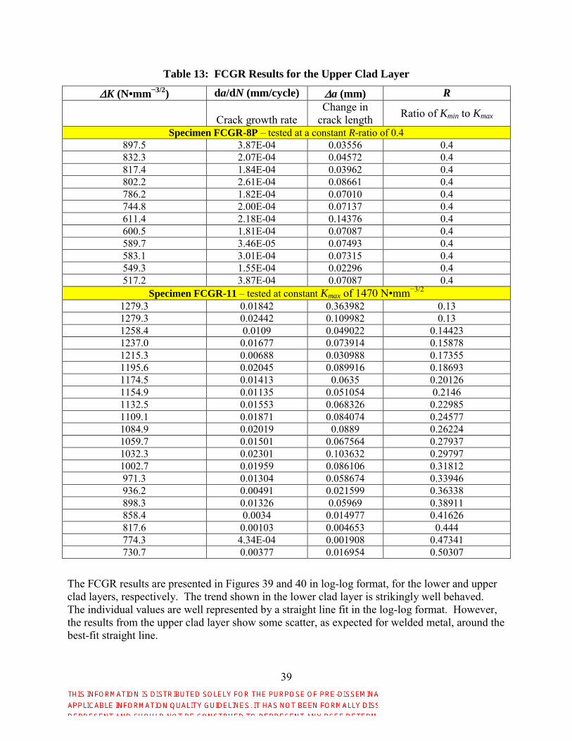
39
Table 13: FCGR Results for the Upper Clad Layer
K (N•mm−3/2
) da/dN (mm/cycle) a (mm) R
Crack growth rate Change in
crack length Ratio of Kmin to Kmax
Specimen FCGR-8P – tested at a constant R-ratio of 0.4 897.5 3.87E-04 0.03556 0.4 832.3 2.07E-04 0.04572 0.4 817.4 1.84E-04 0.03962 0.4 802.2 2.61E-04 0.08661 0.4 786.2 1.82E-04 0.07010 0.4 744.8 2.00E-04 0.07137 0.4 611.4 2.18E-04 0.14376 0.4 600.5 1.81E-04 0.07087 0.4 589.7 3.46E-05 0.07493 0.4 583.1 3.01E-04 0.07315 0.4 549.3 1.55E-04 0.02296 0.4 517.2 3.87E-04 0.07087 0.4
Specimen FCGR-11 – tested at constant Kmax of 1470 N•mm−3/2 1279.3 0.01842 0.363982 0.13 1279.3 0.02442 0.109982 0.13 1258.4 0.0109 0.049022 0.14423 1237.0 0.01677 0.073914 0.15878 1215.3 0.00688 0.030988 0.17355 1195.6 0.02045 0.089916 0.18693 1174.5 0.01413 0.0635 0.20126 1154.9 0.01135 0.051054 0.2146 1132.5 0.01553 0.068326 0.22985 1109.1 0.01871 0.084074 0.24577 1084.9 0.02019 0.0889 0.26224 1059.7 0.01501 0.067564 0.27937 1032.3 0.02301 0.103632 0.29797 1002.7 0.01959 0.086106 0.31812 971.3 0.01304 0.058674 0.33946 936.2 0.00491 0.021599 0.36338 898.3 0.01326 0.05969 0.38911 858.4 0.0034 0.014977 0.41626 817.6 0.00103 0.004653 0.444 774.3 4.34E-04 0.001908 0.47341 730.7 0.00377 0.016954 0.50307
The FCGR results are presented in Figures 39 and 40 in log-log format, for the lower and upper clad layers, respectively. The trend shown in the lower clad layer is strikingly well behaved. The individual values are well represented by a straight line fit in the log-log format. However, the results from the upper clad layer show some scatter, as expected for welded metal, around the best-fit straight line.

40
Figure 39: Summary of FCGR for the lower clad layer under HPHT sour-gas conditions
Figure 40: Summary of FCGR for the upper clad layer under HPHT sour-gas conditions
Paris Law FCGR Material Models
The simplest mathematical model for FCGR is the Paris law, which defines the crack growth rate (da/dN) with an exponential relationship to the change in stress intensity factor (K), as follows:
Equation 6: da/dN = CpKz
where, Cp and z are curve fitting constants, which are material dependent.
As with the fatigue data discussed above, values for Cp and z can be determined by a best-fit linear equation to the log-log form of the da/dN versus K values. For the lower clad layer,

41
whose data are shown in Table 12, the following best-fit equation was determined with da/dN in mm/cycle and K in N•mm−3/2.
Equation 7: da/dN|lower = 3.74 × 10⁻²³K
6.34
The measured values at K = 1219.4 N•mm−3/2 were omitted from the above curve fit since they were far removed from the trends observed otherwise. Relying on the method proposed by Schneider and Maddox [22], one can also compute the one-sided statistical behavior of the FCGR for the lower clad layer; however, here intercepts higher than the best fit are needed to define the population of cracks that grow no faster than the statistically estimated values. For the 18 data samples, JMP computed the root mean square error of da/dN as 0.152578 for 16 degrees of freedom, which is equivalent to 0.148022 for 17 degrees of freedom. The Student-t values are 2.110 and 2.567 at 97.5% confidence and 99% confidence, respectively. The one-sided FCGR statistical curves for 97.5% and 99% are as follows.
Equation 8: da/dN|lower,97.5% = 7.83 × 10⁻²³K
6.34
Equation 9: da/dN|lower,99% = 9.19 × 10⁻²³K
6.34
In similar fashion, using the data in Table 13, one can compute the coefficients of the Paris law for the upper clad layer. Again defining the best fit to the log(da/dN) versus log(K) yields the following material model for the upper clad layer.
Equation 10: da/dN|upper = 9.04 × 10⁻²³K
6.58
For the 33 data samples, JMP computed the root mean square error of da/dN as 0.491986 for 31 degrees of freedom, which is equivalent to 0.484238 for 32 degrees of freedom. The Student-t values are 2.038 and 2.450 at 97.5% confidence and 99% confidence, respectively. The upper confidence limit curves can be determined as follows.
Equation 11: da/dN|upper,97.5% = 9.08 × 10⁻²²K
6.58
Equation 12: da/dN|upper,99% = 1.45 × 10⁻²¹K
6.58
where, K is in N•mm−3/2 and da/dN is in mm/cycle.
Walker Equation FCGR Material Model
The basic form of the Walker equation is:
Equation 13: da/dN = C[K(1 – R)p – 1
]q
where, C, p and q are material-dependent values to be fit to experimental data.
To determine the material-dependent constants (C, p and q), da/dN versus K must be available at multiple values of R. This condition was not met for either of the clad layers. Therefore to develop the Walker equation for the cladding, an alternative approach was employed as discussed here. James [25] offers temperature-dependent values for the variable p in Equation 13 for Inconel 718.12 These values were determined by extracting data from several sources
12 Weld-overlay Inconel 625 on steel produces dilution of iron with concentrations varying from about 26 wt% at the steel interface to approximately 8.5 wt%, at approximately 2500 µm (0.0985″) into the thickness of the first weld layer (see Figure 6). This iron dilution in the Inconel 625 weld overlay indicates that the first weld metal layer should have average iron content closer to that of Inconel 718 alloy (17 wt% Fe). The only alloying element

42
available in previously published papers. The p values reported between −78 °C and 538 °C are between 0.5 and 0.75. Based upon the data provided by James at 350 °F, a p value of 0.670 was assumed for the iron-diluted Inconel 625 in the present work. Reported values of p for other materials – including aluminum alloys and a few steel alloys – are also between 0.5 and 0.75 [26]. Although Equations 7 through 12 can be used with confidence for Inconel 625 clad onto ASTM A387 Grade 22, Class 2 steel substrates, use of 0.670 for the p value of Inconel cladding in the Walker equation will allow a first approximation to the Walker equation for the cladding. The resulting expression fitting the form of Equation 13 for the lower clad layer is as follows with da/dN in mm/cycle and K in N•mm−3/2.
Equation 14: da/dN|lower = 4.87 × 10⁻³³
[K(1 – R)−0.330
]9.46
For the 18 data samples, JMP computed the root mean square error of da/dN as 0.152849 for 16 degrees of freedom, which is equivalent to 0.148285 for 17 degrees of freedom. The Student-t values are 2.110 and 2.567 at 97.5% confidence and 99% confidence, respectively. The upper-bound statistical equations are as follows for the Walker equation defining the FCGR of the lower clad layer.
Equation 15: da/dN|lower,97.5% = 1.02 × 10⁻³²
[K(1 – R)−0.330
]9.46
Equation 16: da/dN|lower,99% = 1.20 × 10⁻³²
[K(1 – R)−0.330
]9.46
For the upper layer the best curve fit with an assumed value of p = 0.670 is as follows.
Equation 17: da/dN|upper = 2.48 × 10⁻²⁶
[K(1 – R)−0.330
]7.63
For the 31 data samples, JMP computed the root mean square error of da/dN as 0.509087 for 31 degrees of freedom, which is equivalent to 0.501069 for 32 degrees of freedom. The Student-t values are 2.038 and 2.450 at 97.5% confidence and 99% confidence, respectively. The upper bound statistical equations are as follows for the Walker equation defining the FCGR of the upper clad layer.
Equation 18: da/dN|upper,97.5% = 2.70 × 10⁻²⁵
[K(1 – R)−0.330
]7.63
Equation 19: da/dN|upper,99% = 4.37 × 10⁻²⁵
[K(1 – R)−0.330
]7.63
Other Forms of FCGR Material Models
The NASGRO equation [26], another commonly used equation to characterize FCGR, could not be determined due to the limited results available from the current test data. Additional FCGR data at varying, controlled R values to supplement those defined above are needed to determine the NASGRO equations for the clad Inconel 625.
exceptions are the approximately 6 wt% higher molybdenum in the Inconel 625 alloy than in the Inconel 718 alloy and the absence of cobalt in the Inconel 625 alloy. Inconel 718 has up to 1 wt% cobalt. Both molybdenum and cobalt are solid solution strengthen elements. Therefore, it is reasonable to assume that the iron diluted in the Inconel 625 weld layer should have roughly similar mechanical properties to those of Inconel 718 cast or weld metal.

43
7.0 FATIGUE AND FRACTURE DATABASE
To aid in the organization of current and future fatigue and fracture data of clad materials, a database has been created and is attached as a separate Microsoft® Access® database file to this report. Future fatigue and fracture data from additional tests on the current material as well as for other clad/substrate materials may be entered into the database for future use and reference.
8.0 CONCLUSIONS
Based upon the findings, the following conclusions are offered.
1. The data and mathematical material models/equations provided in this report are a good start towards having a broad collection of publically available fatigue and fracture data for use by designers, failure analysts and regulatory bodies within the oil and gas exploration and extraction industry for clad components subjected to HPHT sour-gas conditions.
2. No observable cracking or pitting was observed in any of the SCC specimens (three replicates each were tested at 95%, 110% or 120% of apparent yield load), which were subjected to the HPHT sour-gas environment for 30 days.
3. Fatigue and fracture differences were noted between the inner and outer layers of the two-layer weld cladding evaluated in the present project. The differences can be attributed to the iron (Fe) dilution that primarily occurred in the inner layer. Treating each clad layer as a “separate” material in fatigue and fracture assessments is justified.
4. Slow strain rate tensile tests performed in the HPHT sour-gas environment did not show any evidence of environmentally assisted cracking. The fracture surface exhibited a ductile failure mode with no measureable evidence of attack by the Inconel 625 cladding from the HPHT sour-gas environment.
5. Fracture toughness tests performed in air and sour-gas environments in both the upper (low Fe dilution) and lower (high Fe dilution) Inconel 625 clad layers indicated the fracture toughness of both clad layers is high (threshold value of J > 240 N/mm in the lower clad layer and J ~ 190 N/mm in the upper clad layer, where J is fracture toughness). Plane-strain plastic-elastic fracture toughness (JIc, defined as the J value at a crack mouth opening displacement of 0.2 mm) averaged 257 N/mm for the upper clad layer; the singular JIc value for the lower clad layer was 344 N/mm. The fracture surfaces exhibited ductile features, suggesting that neither clad layers were susceptible to environmentally assisted fracture.
6. FCGR frequency scan tests on both the upper (low Fe dilution) and lower (high Fe dilution) Inconel 625 clad layers did not exhibit a strong frequency dependence between 1 Hz and 3 mHz. However, between 1 mHz and 0.1 mHz, FCGR increased by about 100×. Although this suggests that chemical attack occurs at the crack tip, thereby making the material more susceptible to crack growth over time, effects of static growth rate, especially at the lowest test frequencies, may also have played a role in the increased FCGR at low test frequencies. During frequency scans, the lower layer (i.e., the one more highly diluted with substrate material) was found to have a higher FCGR by about an order of magnitude (i.e., 10×) over the upper layer. When the material was tested in the Paris law region, the FCGR of the lower layer was about twice that of the upper layer. These results suggest any crack that starts from the exterior of a cladded component may

44
accelerate its growth rate once the outer clad layer has been completely penetrated and the crack grows into the lower clad layer.
7. To achieve failure within a few hundred to a few thousand cycles, cyclic fatigue specimens must be notched with a stress concentration factor of about 4.0 and subjected to nominal stresses that exceed yield. (For the Inconel 625 cladding evaluated here, the measured 0.2% offset yield strength at 350 °F was 65.9 ksi.) Preliminary fatigue tests on smooth bar tests resulted in runouts, after which additional fatigue tests were performed on notched specimens. Fatigue failures occurred between 4000 to 10,000 cycles in the peak cyclic stress range of 60 to 88 ksi. The log-log relationship between the number of cycles to failure and peak cyclic stress followed a linear relationship with minimal scatter around the best-fit curve, which included peak cyclic stresses both below and above the Inconel 625 cladding yield strength.
8. While the HPHT sour-gas environment may lead to greater scatter (~5%) in tensile elongation, reduction of area and time to failure during slow-strain-rate testing, the mean values of these tensile properties were not significantly altered (~1%) from values measured in air at 350 °F.
9. Additive manufacturing methods were useful for providing material to the top of cladding without impairing its original microstructure/mechanical properties and enable physical completion of fracture and FCGR specimens.
10. The cost of testing under HPHT sour-gas conditions limits the number of specimens that can be tested under a specified budget. In addition, the time to complete a single test under these conditions may take up to 8 weeks, which can place challenges on project scheduling. Fatigue testing under HPHT sour-gas conditions should begin as early as possible when testing any new material in future testing campaigns.
11. Fatigue and fatigue crack growth rate data can be fit to an exponential equation to mathematically define the associated behavior. Both a power law model and Walker equations are provided for FCGR. Due to the limited data (and the cost of generating the data), more sophisticated mathematical models, such as the NASGRO crack propagation model, could not be developed.
9.0 RECOMMENDATIONS
1. Supplement the current FCGR data with additional tests to enrich the present data set. If such measurements are made, especially if completed at a variety of independent K and R values, one can determine more robust mathematical relationships for FCGR including determination of the coefficients for the NASGRO equation.
2. Additional testing of material made by other clad vendors (and from multiple iterations of cladded materials from any given vendor) would provide information on the expected variability in fatigue and fracture behavior of cladding during oil and gas exploration and extraction. Future efforts should consider a test summary as defined in Appendix A.
3. Similarly, while cyclic fatigue testing was completed at a single stress ratio (R = 0.13), completing additional cyclic fatigue tests at other stress ratios (and possibly with other than sinusoidal stress versus time cycles) would provide the industry with additional valuable data.
4. Since other cladding alloys are either being used or are being considered for use by the oil and gas exploration and extraction industry, complementing the present work by
45
assessing the fatigue and fracture behavior of these other materials would also benefit the industry.
5. To determine low-cycle stress-based fatigue curves for common cladding materials, the test should start with nominal peak cyclic stresses just above and just below the yield strength of the cladding.
10.0 REFERENCES
1. INCONEL® alloy 625, Special Metals brochure, http://www.specialmetals.com/.
2. ASTM A387/A387M-17a, “Standard Specification for Pressure Vessel Plates, Alloy Steel, Chromium-Molybdenum,” ASTM International, West Conshohocken, PA, https://www.astm.org/.
3. Steven Shademan, BP, email to Michael L. Tims, CTC, 21 March 2016.
4. ASTM Standard E21, “Standard Test Methods for Elevated Temperature Tension Tests of Metallic Materials,” ASTM International, West Conshohocken, PA, https://www.astm.org/.
5. ASTM Standard E466-15, “Standard Practice for Conducting Force Controlled Constant Amplitude Axial Fatigue Tests of Metallic Materials,” ASTM International, West Conshohocken, PA, https://www.astm.org/.
6. ASTM Standard E1820, “Standard Test Method for Measurement of Fracture Toughness,” ASTM International, West Conshohocken, PA, https://www.astm.org/.
7. ASTM Standard E647, “Standard Test Method for Measurement of Fatigue Crack Growth Rates,” ASTM International, West Conshohocken, PA, https://www.astm.org/.
8. ASTM Standard G129, “Standard Practice for Slow Strain Rate Testing to Evaluate the Susceptibility of Metallic Materials to Environmentally Assisted Cracking,” ASTM International, West Conshohocken, PA, https://www.astm.org/.
9. ASTM Standard G39, “Standard Practice for Preparation and Use of Bent-Beam Stress-Corrosion Test Specimens,” ASTM International, West Conshohocken, PA, https://www.astm.org/.
10. International Standard ANSI/NACE MR0175/ISO 15156, “Petroleum and Natural Gas Industries – Materials for Use in H2S-Containing Environments in Oil and Gas Production,” NACE International, Houston, TX, https://www.nace.org/home.aspx, 2011.
11. ANSI/NACE TM0284, “Evaluation of Pipeline and Pressure Vessel Steels for Resistance to Hydrogen-Induced Cracking,” NACE International, Houston, TX, https://www.nace.org/home.aspx.
12. ANSI/NACE Standard TM0177, “Laboratory Testing of Metals for Resistance to Sulfide Stress Cracking and Stress Corrosion Cracking in H2S Environments,” NACE International, Houston, TX, https://www.nace.org/home.aspx.
13. S. Floreen, G. E. Fuchs and W. J. Yang, “The Metallurgy of Alloy 625,” Superalloys 718, 625, 706 and Various Derivatives, TMS Society, (1994), pp.13–37.

46
14. M. L. Tims, R. Thodla, M. A. Phillippi, J. J. Valencia and D. B. George, “Fatigue and Fracture Properties of Inconel 625 Cladding under High-Pressure High-Temperature Sour-Gas Conditions: Revision 1,” report from Concurrent Technologies Corporation to the Bureau of Safety and Environmental Enforcement, 30 April 2018.
15. ASTM Standard E1457-15, “Standard Test Method for Measurement of Creep Crack Growth Times in Metals,” ASTM International, West Conshohocken, PA, www.astm.org.
16. API Technical Report 17TR8, “High-Pressure High-Temperature Design Guidelines,” First Edition, American Petroleum Institute, www.api.org, product number G17TR81, February 2015.
17. Walter D. Pilkey, Peterson’s Stress Concentration Factors, Second Edition, John Wiley and Sons, Inc., 1997, page 100.
18. W. Werchniak and E. J. Czyryca, “High Cycle Fatigue Properties of Cast Alloy 625 and Alloy 625 Thick Weld Overlay for Propulsion Shaft Seal Sleeve Applications,” David W. Taylor Naval Ship Research and Development Center, Naval Sea Systems Command, Washington, D.C., Report No. DTNSRDC-SME-89-24, January 1990.
19. “Metallic Materials Properties Development and Standardization (MMPDS),” MMPDS-08, Battelle Memorial Institute, 1 April 2013, p. 6-44.
20. American Petroleum Institute Committee API-17TR8, discussion during meetings in 2016.
21. NACE Standard TM0298, “Evaluating the Compatibility of FRP Pipe and Tubulars with Oilfield Environments,” NACE International, Houston, TX, http://www.nace.org.
22. C. R. A. Schneider and S. J. Maddox, “Best Practices Guide on Statistical Analysis of Fatigue Data,” Document IIW-XIII-WG1-114-03, International Institute of Welding, February 2003.
23. JMP statistical analysis software, SAS Institute, Inc., Cary, NC, https://www.sas.com/en_us/home.html.
24. W. Mendenhall and R. L. Scheaffer, Mathematical Statistics with Applications, Wadsworth Publishing Company, Inc., Belmont, CA, 1973.
25. Lee A. James, “Fatigue Crack Propagation in Alloy 718: A Review,” Superalloy 718 – Metallurgy and Applications, Ed. E. A. Loria, The Minerals, Metals & Materials Society, 1989, pp. 499–515.
26. R. G. Forman, V. Shivakumar, J. W. Cardinal, L. C. Williams and P. C. McKeighan, “Fatigue Crack Growth Database for Damage Tolerance Analysis,” U.S. Department of Transportation, Report No. DOT/FAA/AR-05/15, August 2005.

47
APPENDIX A: RECOMMENDED TEST OUTLINE FOR
MEASUREMENT OF FATIGUE AND FRACTURE DATA UNDER HPHT
SOUR-GAS CONDITIONS
1. Three sets of three replicate stress corrosion cracking test specimens tested under high-pressure, high-temperature (HPHT) sour-gas conditions is relatively inexpensive and can serve as a go/no-go evaluation for potential clad materials, application techniques or for vendor pre-qualification.
2. Slow-strain rate testing is likewise a useful tool for qualitatively determining the impact of attack on cladding. A strategy is recommended to test at least two replicate specimens in each combination of temperature (room temperature and the desired elevated temperature) and environment (in air and in HPHT sour-gas).
3. Stress-strain testing in air at the desired elevated temperature is useful for establishing peak cyclic stresses to specify during fatigue testing. At least one such test should be completed.
4. Complete initial set of fatigue tests in air at a wide range of peak cyclic stresses, including stresses above the yield strength (but below the ultimate tensile strength) of the cladding. Complete additional tests at stress levels in the vicinity of the stress causing in-air tests to fail at approximately the desired number of cycles to failure. At that point, complete fatigue tests in HPHT sour-gas conditions under peak cyclic stresses at the low end of the in-air specimens found to be within the desired number of cycles to failure. Although three (or five) replicates are commonly recommended for general fatigue testing, the test team should judge the value of this approach (relative to budget and project period of performance) versus other fatigue considerations, including stress ratio, use of machined notches, desired load frequency and the form of the cyclic load (sinusoidal versus other cyclic loading shapes).
5. Complete fatigue crack growth rate tests by varying K at a given R value. Complete at least three sets of these tests, each at a different R value. Doing so will enable development of robust and broadly applicable fatigue crack growth rate mathematical models.
6. After determining the desired K-rate for testing, complete a minimum of two (and preferably three) fracture toughness tests for each clad layer at the desired K-rate.