chemistry - ari armaturenin.ari-armaturen.com/fileadmin/user_upload/ari-in/files/chemistry.pdf ·...
TRANSCRIPT
ChemistryChemistry is the study of matter and the changes that take place inside that matter. Our matter here issteam and the boiler. Wet steam, steam and air, feed water and air, combustion - these are some of thetopics here.
Quality of steam
Dry steam
Steam and air don't mix
Clean, clean steam
Feed water quality
Heating feedwater
Deaeration
Chemical dosing of feedwater
TDS control
Combustion
Quality of steam
Steam may be at the correct pressure and temperature, but the quality of steam is very important as well. Good quality steam must be dry. Dry steam is steam which has a very high dryness fraction, ie almost no moisture. Unfortunately, in most steam systems we are faced with wet steam. Wet steam is steam containing a degree of water. It can reduce plant productivity and product quality, and can cause damage to most items of plant and equipment. It can cause erosion and affect heat transfer processes.
What is the ideal steam quality?
• Steam must not be wet, but with as high a dryness fraction as possible.• There should be no air present in steam.• Steam should not contain any dirt.
Only then do we deliver it to our process.
Dry steam
Dryness fraction achieved from a typical shell boiler where the heat is supplied only to the water and where the steam remains in contact with the water surface, typically contains around 5% water by mass. If the water content of the steam is 5% by mass, then the steam is said to be 95% dry and has a dryness fraction of 0.95. This is because bubbles of steam break through the water surface and they cause turbulence and splashing. Therefore the steam space contains a mixture of water droplets and steam. This kind of steam is called wet steam.
(c) ARI Steamline 2014 Page 8.1 Chemistry
The actual enthalpy of evaporation of wet steam therefore is only 95% of the one in the steam table. So, wetsteam has lower usable heat energy than dry saturated steam. Also, the specific volume of water is much lower than steam. Therefore, the total specific volume of steam will also reduce by the same factor.
Causes of wet steam
• The boiler itself generates saturated steam which is inherently wet. Most shell type steam boilers produce steam with a dryness fraction of between 95 and 98%.
• Priming and carryover beacause of foaming and scale within the boiler shell increase wetness still further.
• Steam condenses on the way from the boiler to the process as there is always a certain degree of heat loss from the distribution pipe. The condensed water molecules will eventually gravitate towards the bottom of the pipe forming a film of water. Steam flowing over this water can raise ripples that can build up into waves. The tips of the waves tend to break off, throwing droplets of condensate into the steam flow.
Problems caused by wet steam
• Water – a heat barrier. Water doesnt allow the heat in the steam to cross over to the process, ie themedium to be heated. You can see the temperature drop because of the layer of moisture in the steam pipe. This hampers not just plant productivity by increasing the cost of fuel, but also product quality.
• Waterhammer. Failure of valves and flowmeters due to rapid wear or waterhammer.
• Corrosion and Wiredrawing. Water droplets increase the amount of corrosion. Water droplets travelling at high steam velocities will erode valve seats and fittings, a condition known as wiredrawing.
• Erratic operation of control valves and flowmeters beacause of the above.
• Scaling. Pure steam cannot carry any impurities, but water can. These impurities only increase scaling of pipework and heating surfaces.
Understanding Water hammer
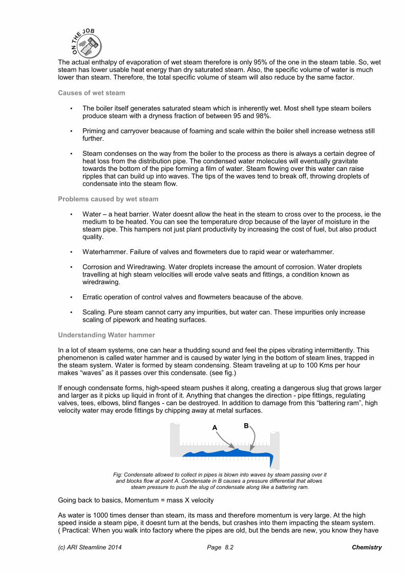
In a lot of steam systems, one can hear a thudding sound and feel the pipes vibrating intermittently. This phenomenon is called water hammer and is caused by water lying in the bottom of steam lines, trapped in the steam system. Water is formed by steam condensing. Steam traveling at up to 100 Kms per hour makes “waves” as it passes over this condensate. (see fig.)
If enough condensate forms, high-speed steam pushes it along, creating a dangerous slug that grows largerand larger as it picks up liquid in front of it. Anything that changes the direction - pipe fittings, regulating valves, tees, elbows, blind flanges - can be destroyed. In addition to damage from this “battering ram”, high velocity water may erode fittings by chipping away at metal surfaces.
Fig: Condensate allowed to collect in pipes is blown into waves by steam passing over itand blocks flow at point A. Condensate in B causes a pressure differential that allows
steam pressure to push the slug of condensate along like a battering ram.
Going back to basics, Momentum = mass X velocity
As water is 1000 times denser than steam, its mass and therefore momentum is very large. At the high speed inside a steam pipe, it doesnt turn at the bends, but crashes into them impacting the steam system. ( Practical: When you walk into factory where the pipes are old, but the bends are new, you know they have
(c) ARI Steamline 2014 Page 8.2 Chemistry
A B

problems with moisture and water in their system).
If its not removed by moisture separators or drained by traps, it can cause a lot of damage to the steam system.
Moisture SeparatorHow do you know a plant needs a moisture separator? When a plant experiences reduced heat exchanger efficiency, erosion at pipe directional changes, erosion to in-line equipment and water hammer, the installation of a separator is a must. All are possible indicators that the presence of entrained condensate particles and the accumulation of condensate exists in the flow of steam.
Moisture separators remove the moisture that remains suspended in the steam flow, which cannot be removed by either drainage or steam trapping. The separator is designed to work in-line and removes approximately 95 - 98% of the entrained condensate particles.
Water drops have more mass and therefore more inertia than steam. (Water hammer is caused because ofthis same reason, as, at bends the steam passes easily, but the water slug crahes into the bend causing damage.)
In the ARI Steamline plate type moisture separator we take advantage of this inertia difference between water and steam. The Msep contains intercepting plates in its body. The steam + water mix has to change direction a number of times to go through.
Fig: Inside a Moisture separator
What happens? First, the separator has a larger cross-section than the pipe. As the steam, with the entrained condensate particles, enters the chamber of the separator it suddenly and momentarily looses some of its velocity due to the sudden enlargement of the separator chamber. Some drops just fall to the bottom of the separator as condensate. The mass of most condensate particles propels them forward into the impingement baffles. These drops have too much inertia and mass to change direction when they hit theplates, so they just collect on them or the outer perimeter wall of the separator chamber and collect at a low point in the separator. The dry steam flows around the intercepting plates and comes out on the other side.
The MSep is fitted with a suitable steam trap module from the bottom to ensure the efficient removal of condensate, without the loss of live steam.
There are other types of separators in use like the cyclonic and coalescence types of separator, but the plate-type has an acceptable efficiency for steam velocities which are typically in the range of 10 m/s to 30 m/s.
Steam and air don't mix
Effect of Air on Steam TemperatureWhen air and other gases enter the steam system, they consume part of the volume that steam would otherwise occupy. The temperature of the air/steam mixture falls below that of pure steam. There are tablesavailable that show the various temperature reductions caused by air at various percentages and pressures.Effect of Air On Heat TransferThe normal flow of steam towards the heat exchanger surface carries air and other gases with it. The steam
(c) ARI Steamline 2014 Page 8.3 Chemistry

velocity pushes the gases to the walls of the heat exchangers, where they may block heat transfer. This compounds the condensate drainage problem, because these gases must be removed along with the condensate.
Since they do not condense and drain by gravity, these non-condensible gases set up a barrier between the steam and the heat exchanger surface. The excellent insulating properties of air reduce heat transfer. In fact ,under certain conditions as little as ½ of 1% by volume of air in steam can reduce heat transfer efficiency by 50 % as seen in the figure below.
Fig. Steam condensing in a heat transfer unit moves air to the side of the heat transfer area.Here, the air collects or "plates out" to form effective insulation.
When non-condensible gases (primarily air) continue to accumulate and are not removed, they may gradually fill the heat exchanger with gases stop the flow of steam altogether. The unit is then “air bound”.
An air film 1mm thick has the same resistance to heat transfer as water 1" thick or iron 4.3" thick.. As a film it acts as an insulator, in solution with steam it deprives the steam of its full heating potential. In other words,air will assume a part of the total volume or pressure that is available. This is explained by Daltons Law of Partial Pressures.
Daltons Law of Partial PressuresIn gas mixtures, each gas assumes a part of the total volume or pressure. This is referred to as partial pressure. The partial pressure of each gas is dependent upon its proportion of the total mixture.If we were to have a total steam line pressure of 5 kg/cm2 g consisting of 80% steam and 20% air the effective steam pressure would be:
0.80x 5 = 4.0 kg/cm2 g
And the effective air pressure would be: 0.20x 5 = 1.0 kg/cm2 g
As a result the steam would effectively be 4 kg/cm2g steam in a 5 kg/cm2g line. In checking a thermometer in the line at that location we would find the temperature to be 151.2° C for the 4 kg/cm2g steam and not 158.2° C for the 5 kg/cm2g steam we would expect to find. That is a 7°C difference between the two pressures. In addition there will also be a change in kcal's.(Although the 4 kg/cm2g steam has more enthalpy of latent heat per weight than does the 5 kg/cm2g steam it has less by volume. Latent heat of evaporation at the 5 kg/cm2g is 498.3 kcal/kg while for 4 kg/cm2g is 509.5 kcal/kg. It shows a difference of 11.2 kcal/kg.)
Steam chamber 100% steamTotal pressure 5 kg/cm2g
Steam pressure 5 kg/cm2gSteam temperature 158.2 °C
Steam chamber 80% steam & 20% airTotal pressure 5 kg/cm2g
Steam pressure 4 kg/cm2gAir pressure 1 kg/cm2g
Steam temperature 151.2 °CFig: Chamber containing air and steam delivers only the heat of the
partial pressure of the steam, not total pressure.
In effect the air has displaced a portion of the enthalpy needed, by displacing a portion of the steam. In order to make the distribution system as efficient as possible it becomes necessary to remove any air beforeit can effect heat transfer by filming or becoming mixed with the steam.
(c) ARI Steamline 2014 Page 8.4 Chemistry
A B

CorrosionBecause boiler systems are constructed primarily of carbon steel and the heat transfer medium is water, thepotential for corrosion is high. Iron is carried into the boiler in various forms of chemical composition and physical state. Most of the iron found in the boiler enters as iron oxide or hydroxide. Any soluble iron in the feed water is converted to the insoluble hydroxide when exposed to the high alkalinity and temperature in the boiler.
These iron compounds are divided roughly into two types, red iron oxide (Fe2O3) and black magnetic oxide (Fe3O4). The red oxide (hematite) is formed under oxidizing conditions that exist, for example, in the condensate system or in a boiler that is out of service. The black oxides (magnetite) are formed under reducing conditions that typically exist in an operating boiler.
The deposition of these metallic oxides in the boiler is frequently more troublesome than the actual damage caused by the corrosion. Deposition is not only harmful in itself, but it offers an opening for further corrosion mechanisms as well.
Contaminant products in the feed water cycle up and concentrate in the boiler. As a result, deposition takes place on internal surfaces, particularly in high heat transfer areas, where it can be least tolerated. Metallic deposits act as insulators, which can cause local overheating and failure. Deposits can also restrict boiler water circulation. Reduced circulation can contribute to overheating, film boiling and accelerated deposition.
Localized attack on metal can result in a forced shutdown. The prevention of a forced shutdown is the true aim of corrosion control.
Clean, clean steam
StrainersThey are used to provide clean steam to the process. Strainers are installed in the steam pipes to ensure that no dirt gets through with the steam. Often, pipeline debris such as dirt, metal burrs from welding, scale, rust and other solids find their way into the steam pipes leading to more maintainance hassles and plant shutdowns. Strainers are an important pipeline accessory that literally 'strains out' these solids in flowing liquids or gases, and protects steam equipment. Every important equipment like a PRV or trap has to have a strainer fitted upstream, ie just before it.There is a fine mesh provided in the strainer which effectively filters out solids from the system. During routine maintenance strainers must be cleaned regularly otherwise unclean steam will go through and damage the plant pipework and fittings. It may contaminate the product as well.
ARI Steamline makes two strainers. The CRPS and trap modules have the Y-strainers and the PRS has a 'bucket' strainer.
Y-type Strainers. These strainers are manufactured in-house for the CRPS and the Trap modules. These are standard strainers and can be used for steam, any other gas, or even liquids. The body is a cylindrical pipe and has a mesh pocket attached to it which contains the strainer mesh (80microns). This filters out all the solids. It can handle pressures upto 10 kg/cm2g and is available in line sizes upto 2". Generally used for condensate or small steam lines.
As the Y-type strainers are more compact than the pot strainers, the surface area of the mesh available for straining is less and therefore, the dirt accumalates faster. This means more frequent cleaning. This is only a problem during commissioning when the plant is new and a lot of welding grit is present in the pipes.
Installation of Y-type strainers.
• For Steam : Horizontal mounting with drain pocket in the horizontal plane prevents water collection, which prevents carryover.
• For Liquids : For eg. in our CRPS systems, the strainer is mounted with the mesh pocket facing vertically down. If this is not done, the water may draw back the dirt upstream if the flow reduces.
(c) ARI Steamline 2014 Page 8.5 Chemistry
Steam / gas
LiquidDownward
flow

• If you install the strainer with the mesh pocket pointing up, all the debris will fall into the pipe!!
Bucket strainers.The ARI Steamline pot strainer has a bucket type structure. This is a vertical cylinder. It's chamber is larger than a typical Y-type strainer. The straining area is therefore much larger and can go without cleaning longer. This also reduces the pressure drop across the pot strainer as the flow is not hampered by that much debris. The bucket strainer can be used on bigger dia pipes. Strainers may have accumalated debris in the bottom of the bucket, which is removed via the drain plug.
Bucket strainers have to be installed in a horizontal position only.
(c) ARI Steamline 2014 Page 8.6 Chemistry
Wronginstallation

Feed water quality
Feed water purity requirements can vary widely. A low pressure firetube boiler can usually tolerate a high level of water hardness, with proper chemical treatment, while virtually all impurities must be removed from the feedwater of most modern high pressure water-tube boilers. Most plants use one or more of the following processes.
• Clarification• Filtration• Softening• Dealkalization• Demineralization• Deaeration• Heating
What is ideal feedwater like? Ideally feedwater should conform to the following:
• We must supply boiler feedwater at not less than 75 - 85°C. • We must remove dissolved gases, ie, de-aerate feedwater. Dissolved gases like oxygen lead to
corrosion inside the boiler.• Feedwater needs chemical treatment to avoid excessive foaming and scaling in the boiler. This can
result in other problems like carryover, priming, dirty and wet steam which hamper efficiency and cause untold damage to the boiler.
Heating feedwater
Cold make-up water and returned Condensate usually mix in the feedtank. Conventionally, both make-up water and condensate are fed to the feedtank above the water surface.
We heat feedwater because of three reasons.
• Cold feed will result in thermal shock to the boiler. When we feed at optimum temperatures the life of boiler is also prolonged
• When feedwater is at the highest temperature for injection to the boiler, the boiler efficiency increases drastically. Return of condensate further boosts η.
• All water sources have a certain amount of dissolved gases mixed in them at ambient temperature. Cold water absorbs free oxygen and other gases. As the condensate heats the make-up water, the temperature of the make-up water rises. At high temperatures undesirable gases have minimum solubility and are liberated when heated.
DeaerationAir is always present during equipment start-up and in the boiler feed-water. The most common source of corrosion in boiler systems is dissolved gas: oxygen, carbon dioxide and ammonia. Of these, oxygen is the most aggressive. The importance of eliminating oxygen as a source of pitting and iron deposition cannot be over-emphasized. Even small concentrations of this gas can cause serious corrosion problems.
Pic: Corrosion caused by dissolved gases
(c) ARI Steamline 2014 Page 8.7 Chemistry

Makeup water introduces appreciable amounts of oxygen into the system. Oxygen can also enter the feed water system from the condensate return system. Possible return line sources are direct air-leakage on the suction side of pumps, systems under vacuum, the breathing action of closed condensate receiving tanks, open condensate receiving tanks and leakage of nondeaerated water used for condensate pump seal and/or quench water. With all of these sources, good housekeeping is an essential part of the preventive program.
One of the most serious aspects of oxygen corrosion is that it occurs as pitting. This type of corrosion can produce failures even though only a relatively small amount of metal has been lost and the overall corrosion rate is relatively low. The degree of oxygen attack depends on the concentration of dissolved oxygen, the pH and the temperature of the water.
The influence of temperature on the corrosivity of dissolved oxygen is particularly important in closed heaters and economizers where the water temperature increases rapidly. Elevated temperature in itself does not cause corrosion. Small concentrations of oxygen at elevated temperatures do cause severe problems. This temperature rise provides the driving force that accelerates the reaction so that even small quantities of dissolved oxygen can cause serious corrosion.
It is essential to remove the dissolved gases – "deaerate" – before it can be released in the boiler or the feedtank, to prevent corrosion of the tank, the boiler and the steam system.
The feedwater used in generating steam will, of course, contain oxygen. It can also contain bicarbonate and carbonate alkalinities which, when broken down due to high temperatures, will produce C02. These two gases, O2 and CO2, alone or combined, when disolved in condensate are very corrosive. The oxygen causes oxygen pitting while the carbon dioxide, in solution with the condensate, forms carbonic acid. When combined, the oxygen accelerates the corrosive effects of the acid.
Deaerating the feedwater removes almost all of these gases. In general, as the feedwater enters the deaerator low pressure steam, typically 0.35 kg/cm2 g, is used to break up the water into a spray continuing across the spray carrying off the gases.
All modern boilers have some form of deaeration arrangement. The removal of this oxygen can be done by three ways – thermal, mechanical and chemical.
• In chemical removal of oxygen, an oxygen scavenger like Sodium Sulphite is dosed to the feedtank,which absorbs the oxygen. However, this is detrimental because the addition of any chemical to the boiler water increases its TDS (explained later in this section), again causing problems.
• In mechanical de-aeration, water is stirred or sprayed, causing removal of oxygen from the feed water.
• Thermal de-aeration uses the property of water shown in the graph below. As is seen, the amount of dissolved oxygen in water is proportional to its temperature. So if we can heat the make-up water before it enters the feedtank, it will liberate the oxygen, thus preventing corrosion of the tank. Further, if the system used to preheat the make-up is made of Stainless Steel, corrosion will be negligible.
Pic: Graph showing what happens to dissolved oxygen in water as temperature is raised
(c) ARI Steamline 2014 Page 8.8 Chemistry

What is the job of a deaerator?
• Deaerators remove oxygen, carbon dioxide and other noncondensable gases from feed water. Oxygen and carbon dioxide are very harmful to boiler systems. Deaerators are designed to remove dissolved gases from boiler feedwater. They are effective and oxygen can be reduced to trace levels, about 0.005 ppm.
• Along with temperature control systems, an effective deaeration system can heat the incoming cold makeup water and mix it with available return condensate.
Fig. Cutaway of a pressurized deaerator tank with live steam sparging
ARI Steamline Deaerators – how do they work?
On larger boiler plants, pressurised de-aerators like the one shown above are installed. Live steam is used to bring feed water temp above 100ºC to “drive off” the oxygen content. This action is normally enhanced by the steam “scrubbing” the feedwater. The make-up water enters the deaerator and is broken into a spray or mist, and scrubbed with steam to force out the dissolved gases. At the elevated temperature the solubility ofoxygen is extremely low. Steam and other non-condensibles flow upwards into the vent condensing section where the steam is condensed. Freed oxygen and other gases are vented to the atmosphere through the vent outlet. However, these are pressure vessels and are therefore expensive.
This type of deaerator usually consists of a heating and a deaerating section. The storage section of these units typically have a residual deaerated feedwater storage tank often designed to hold about 10 mins of rated capacity of boiler fedwater.
Pic: Pressurized ARI Steamline deaerator at a Pharma plant
(c) ARI Steamline 2014 Page 8.9 Chemistry

Accordingly, the Deaerator Head was developed – a compromise for fitting to any feedtank to drive off asmuch oxygen as possible at atmospheric pressure. The ARI Steamline De-aerator Head uses acombination of thermal de-aeration and mechanical de-aeration. It has three restrictions to the flow – anozzle in the make-up line, a baffle plate between the mixing head and the immersion tube, and a sparger inthe immersion tube. Therefore it ensures that the oxygen in the make-up water is driven off by using theheat in the condensate which it is mixed with, and all the dissolved gases are released in the De-aeratorHead before it enters the feed tank and the boiler. These are vented out by the automatic Air Vent on top ofthe De-aerator Head.
Pic: An ARI Steamline Flash condensing Deaerator Head has an all SS assemblyand is fitted to the top of the feedtank with inlets for condensate, make-up water and flash steam.
In addition, sometimes Flash Steam is generated from high pressure Condensate. This flash steam will escape to the atmosphere and the heat will be lost. A third inlet is sometimes provided in a De-aerator Headto mix flash steam with make-up water, thus condensing the flash steam and saving its heat. This type of unit is called the Flash Condensing De-aerator Head.
Deaerators are typically elevated in boiler rooms to help create head pressure on pumps located lower. Thisallows hotter water to be pumped without vapor locking should some steam get into the pump.
Chemical dosing of feedwaterThe basic contaminants are reduced to a minimum, consistent with boiler design and operation parameters.That is - calcium and magnesium hardness, migratory iron, migratory copper, colloidal silica, etc.
Ion exchange systemsIon exchange systems range from light commercial water softeners and filters to specially designed industrial equipment. Also known as deionizations (DI) systems. These systems are considered high-end where the highest quality of water treatment is needed, such as with steam turbines.
Reverse Osmosis (RO)Reverse Osmosis systems are available for tap water, brackish water or seawater. These systems are considered high-end where the highest quality of water treatment is needed, such as with steam turbines.
(c) ARI Steamline 2014 Page 8.10 Chemistry

TDS control
Water that is fit for human consumption is not necessarily fit for a boiler. This is because water can have many dissolved solids that lead to " hardening " of water. These cause scaling which in turn leads to '' hot spots" in the boiler which lead to corrosion.
Boiler feed water contains dissolved solids, both from raw water and water treatment chemicals. As steam israised from a boiler, the level of concentration of Total Dissolved Solids (TDS) in the boiler water increases.
The maximum allowable TDS is 3500 ppm for any boiler. This seems very small. How can such a small value affect the working of such a large body of water inside the boiler?
The salt truck storySuppose the TDS in a boiler is 200 ppm (Parts Per Million). This gives us a percentage value of
200 / 1,000,000 X 100 = 0.002 %
This salt does not evaporate. So, over time the TDS valves keep rising. 0.002% is seeming such a small number, but look what happens inside the boiler.
We assume a 10 ton boiler working 3 shifts ( 24 hours) for 30 days. The feed water has 200 ppm TDS.
We will have 14.4 kgs of salt in 30 days. So, in a few months we will have a small truck-load of salt in the boiler!
Lets see if the TDS can be reduced in a water softening plant.
Water softening and TDSTotal Dissolved solids (TDS) is the sum of both Hard and Soft salts.
A water softener basically uses chemicals to remove (precipitate) the hand salts and substitutes it with a soft salt. It does this by a reaction called base exchange softening.
Ca SO4 + Na OH --------Na 2 SO4 + Ca OH
Soft salt + Hard salt precipitate
Before softening,
Hard salts + Soft salts = TDS10 + 90 = 100
After softening,
Hard salts + Soft salts = TDS2 + 98 = 100
So, unfortunately, while a water softening plant reduces the “hardness” (i.e. the presence of scale forming salts), it does not reduce the TDS of the feed water. In practice we may in fact, find a slight rise in TDS as brine (NaOH) gets added to precipitate the hard salts. So, in a boiler the foaming and carryover problems remain as the TDS has not decreased. The only issue we have dealt with is reduced the scaling because the hard salts are precipitated.
Even if we use RO water, the Boiler water TDS keeps rising, albeit slowly. Normally, plants periodically drain10-15% of the boiler water and this is called blowdown.
High TDS, big problems
Foaming & CarryoverPure water does not foam when it boils. However, as the amount of impurities rise, a foam layer is formed atthe steam separation surface. The amount of foaming is directly proportional to the TDS level in the boiler.
Foaming (or “priming”) causes carryover of water, or wet contaminated steam, which may be carried over into the steam system and depending on the conditions at the steam water interface, can even cause surges of water into the steam system. The products of carryover would be deposited on heat transfer surfaces and ancillary equipment, reducing steam system efficiency and plant productivity. This is what causes fouling of heat exchangers, malfunctioning of control valves and steam traps etc.
(c) ARI Steamline 2014 Page 8.11 Chemistry

Pic: Scaling caused by foaming leads to material failure
Formation of foam at the separation layer is a matter of great concern for any boiler operator. Level controls in a boiler recognize liquids and gas. But, they start malfunctioning when confronted with foam in the boiler. We know that the water must never drop below the fire tube level. If the water level is falling, but the foam prevents a level control from sensing low level water the feed pumps do not switch on and a potentially dangerous situation could develop.
Fig: Foaming and carryover in a boiler
Scale DepositionIf the TDS is too high, scale will deposit on the boiler tubes and furnace (water side), all the heat transfer surfaces. This has the effect of reducing heat transfer with its subsequent effect on fuel consumption. Whenscaling goes up exponentially, as seen in the graph, tube failure can occur.
Scaling is not linear ,it is exponential
Scale
Time
Pic: Graph showing scale deposition with time
Scale only 1mm thick on the water side could increase fuel consumption by 5 to 8%.(Source: PCRA Handbook No. 3 - Efficient Generation of Steam)
(c) ARI Steamline 2014 Page 8.12 Chemistry
NOTE

Tube surfaces underneath the scale may become overheated leading to tube damage or tube failure. High TDS levels in a boiler also shows up in the steam system -valves get while deposits strainers need to be cleaned very often, etc.
In order to prevent these problems, the TDS needs to be controlled within a certain specified maximum limit.The chart below shows the recommended water characteristics for shell boilers in accordance with IS: 10392-1982 and BS: 2486-1964, for pressures up to 25 bar g:
The Dissolved solids, PPM (parts per million) is 3500. This is the Set point of TDS that no boiler should be allowed to across because of scale, foam and carryover problems. This set point can be measured by a conductivity meter dipped in a sample of boiler water. (Conductivity is directly proportional to TDS levels.)
BlowdownAll steam boilers need to be "blown down" to control their TDS level. The main purpose of blowdown is to maintain the solids content of the boiler water within prescribed limits. This would be under normal steamingconditions. However, in the event contamination is introduced in the boiler, high continuous and manual blowdown rates are used to reduce the contamination as quickly as possible. Because each boiler and plantoperation is different, maximum levels should be determined on an individual basis.
Bottom BlowdownConventionally, this is done through a manual slide valve. By definition, bottom blowdown is intermittent and designed to remove sludge or sediment from the bottom of the boiler where it settles. The frequency of bottom blowdown is a function of experience and plant operation. Bottom blowdown can be accomplished manually or electronically using automatic blowdown controllers. The control is a large (usually 25 to 50 mm)key operated valve. This valve might normally be opened for a period of about 1 - 2 minutes, once a shift.
Disadvantages• A large quantity of hot, saturated water is drained and the same amount of relatively cold make-up water
is added. This leads to thermal shock in the boiler.• As we now have to provide more heat to bring this extra water to 100ºC, we are decreasing the overfall
efficiency of the boiler
The formula for amount of blowdown required is
Where,F = Feedwater TDS in ppmB = Boiler water set point in ppmS = Steam generation in kg/hr.
Continuous BlowdownFrequently used in conjunction with manual blowdown, continuous blowdown constantly removes concentrated water from the boiler.
Continuous blowdown allows for better control over boiler water solids. In addition, it can remove significant levels of suspended solids. Another advantage is that the continuous blowdown can be passed through heatrecovery equipment.
How much blowdown is enough?Too little, and your TDS could rise above limits specified for your boiler, giving rise to foaming, scaling and wet steam. Too much, and you're draining water that you've paid to heat.
(c) ARI Steamline 2014 Page 8.13 Chemistry
Blowdown (in kgs) = F
B - FX S

The need for Automatic Blowdown Controller (ABCO)Blowdown of the boiler can keep TDS within the required limits. Blowdown is achieved either by manual or automatic methods. In the manual method, blowdown is achieved by opening a large bore valve at the bottom of the drum (or on the side of the drum in case of continuous blowdown). However, this practice can be highly wasteful. As the period of blowdown is not related with either boiler steam load or feedwater purity,the TDS level in manual methods can vary greatly, causing an average TDS level much lower than the allowable limit, and leading to excess blowdown.
On the other hand, an automatic blowdown control system, based on TDS measurement and subsequent corrective action, can maintain a TDS level much closer to the set point, resulting in considerable fuel savings.
Fig: Blowdown quantity is reduced with an automatic system
As seen in the graphs above, the automatic control of TDS results in an average TDS level much closer to the set point. This means that the actual quantity of blowdown over a period of time gets reduced compared to the manual method.
Blowdown water is water that has been heated to the saturation temperature of the boiler, so it contains a lotof heat. At a boiler pressure of 10.5 Kg/cm2 g, each kg of blowdown water contains almost 190 kcal of heat energy. If an automatic boiler controller can reduce the blowdown of a 10 TPH boiler from 6% to 3%, i.e. a saving of 3%, the blowdown quantity would reduce by 300 Kg/hr, or 7200 kg/day. This would mean a saving of 1368000 kcal/day. This would mean a fuel saving of approximately 180 litres of oil, if the boiler was fired with furnace oil. The cost benefit of preventing corrosion in the boiler and the steam system, though it cannot be quantified exactly, would be in addition.
(c) ARI Steamline 2014 Page 8.14 Chemistry

Combustion
Combustion is a process of oxidation in which combusinble products such as fuel is burned in the presence of oxygen. Combustion liberates heat and by products such as ash.
BurnerFor liquid or gaseous fuels, we use a Burner. A burner sends heat into the boiler tubes and it is set tomaintain the correct pressure in the boiler. If the boiler pressure falls because of growing steam demand,the burner switches on to produce more steam from the boiler. As long as the amount of steam beingproduced in the boiler is as great as that leaving the boiler, the boiler will remain pressurised. This maintainscorrect pressure. If correct pressure is maintained, correct temperature is also maintained as they areinterlinked.
Proper atomised fuel gives better combusion efficiencies. Modulating control gives optimum fuel handling.Also provision of appropriate excess air for combusion gives good results.
In case of gaseous fuels, minimum excess air is required and there is no extra cost incurred in handling thisfuel as there are no by products formed. It's a clean fuel.
Fire grateIn case of solid fuels, there is no burner required. Fuel is supplied over a grate which is fire pulverised, and excess air is supplied to acheive better combusion efficiencies. Ash handling is main problem incase of solid fuels.
Boiler TurndownTurndown tells us the amount of control we have over the fuel.
• In a simple on-off control, the boiler either fires x amount of fuel or is switched off.
• A boiler turndown of 1.2 means we can fire less fuel on more fuel. A 1:2 turndown means a 2 step control is possible.
• 1:4 turndown looks something like this. It has 4 step control. Modern boilers can also provide a stepless control from 25-100%.
As fuel load increase or decreases, the amount of fuel fired into the boiler should proportionately be increased or decreased. But when modulation is not possible, (as in a simple on-off control) , the boiler burns less fuel at low loads and the rest of the unburnt fuel is blown out through the stack.
(c) ARI Steamline 2014 Page 8.15 Chemistry
ONOFF
OFF100%
50%
OFF
75%25%
50%
100%

Excess Air The boiler furnace has a punker plate (similar to our home gas burners ) through which a pressurized mixture of liquid fuel and air is sprayed. This atomizes the fuel and a proper mixing of fuel with air takes place. This ensures the highest combustion efficiency. Solid fuels too are crushed or broken down (there is always a coal crusher at power plants) to increase the combination efficiency.
Perfect combustion is attained when the flue gas analysis shows no carbon monoxide or oxygen. This means that every available fuel molecule and every available oxygen molecule came into contact with each other.
Ideally, the Combustion Equation (stoichiometric air) should look something like this:
Cn Hn + O2 ------> CO2 + H2O + Heat Fuel Air
The O in the left side of the equation is the exact amount of air required to burn a given amount of fuel, also called stoichiometric air quantity. Given complete mixing, a precise amount of air (stoichiometric) is requiredto completely react with a given quantity of fuel.
Practically though, such perfect mixing is not possible, even with the most advanced burner and the amount of air needed is in excess of this, to achieve complete combustion of fuel. Therefore we provide "excess air".
In practice, if only stoichiometric amount of air is provided, then the combustion looks something like this:
Cn Hn + O2 ------> CO2 + H2O + CO + HeatFuel Stoich. Air (unburnt fuel)
As seen above, CO (unburnt fuel) is present in the flue gas as the stoichiometric air quantity is insufficient toensure complete combustion.
Therefore, additional or “excess air” must be supplied for complete combustion to occur. The presence of excess air means that more air is available for combustion than is actually required. Hence the real world combustion equation, looks like this:
Cn Hn + S2 + N + O2 ------> CO2 + H2O + Heat + O2 + SOx + NOx Fuel Excess Air Undesirable by-products
There is no CO component anymore. For efficiency reasons, “excess air” is always provided to assure that all fuel is burned inside the boiler. Excess air from 20-30% is normally used.
In addition, air has other components besides O2, and fuel may have impurities like sulphur. However, the excess air passing through the boiler is heated by the fuel, and vented out of the chimney. So,the more the excess air, the lower the boiler efficiency. We also have to carefully control this excess air quantity as we risk blowing out unburnt fuel. Hence, excess air must be optimized such that it is just enough to burn all the fuel while not removing too much heat, i.e., decrease stack heat losses and increase combustion efficiency.
Large, unnecessary amounts of excess air can occur because of:♦ Burner/control system imperfections♦ Variations in boiler room temperature, pressure, and relative humidity♦ Need for burner maintenance♦ Changes in fuel composition
In modern history, excess air is controlled using a feedback system in which a sensor (generally O2) is usedto provide feedback on flue gas constituents and controls the amount of combustion air provided to the boiler. This is called Trim Control, or Combustion Control.
Tuning and keeping a boiler running well is not an easy task but we must ensure that it runs efficiently, or else the losses can really add up over time.
(c) ARI Steamline 2014 Page 8.16 Chemistry