chevron final investigation report 2015-01-28
DESCRIPTION
Chevron Final Investigation Report 2015-01-28TRANSCRIPT
U.S. CHEMICAL SAFETY AND HAZARD INVESTIGATION BOARD
FINAL INVESTIGATION REPORT
REPORT NO. 2012-03-I-CA JANUARY 2015
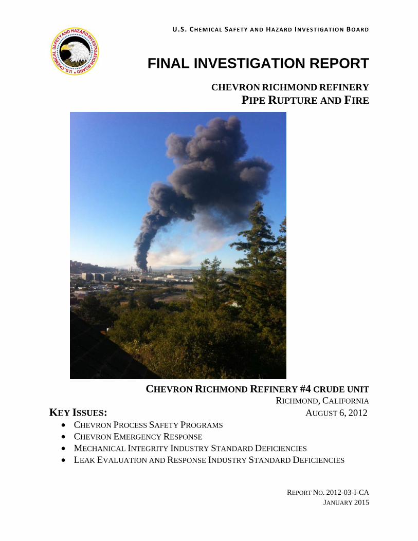
CHEVRON RICHMOND REFINERY
PIPE RUPTURE AND FIRE
CHEVRON RICHMOND REFINERY #4 CRUDE UNIT RICHMOND, CALIFORNIA
KEY ISSUES: AUGUST 6, 2012 CHEVRON PROCESS SAFETY PROGRAMS CHEVRON EMERGENCY RESPONSE MECHANICAL INTEGRITY INDUSTRY STANDARD DEFICIENCIES LEAK EVALUATION AND RESPONSE INDUSTRY STANDARD DEFICIENCIES

Chevron Richmond Refinery Investigation Report January 2015
ii U.S. CHEMICAL SAFETY AND HAZARD INVESTIGATION BOARD
[This page intentionally left blank.]

Chevron Richmond Refinery Investigation Report January 2015
iii U.S. CHEMICAL SAFETY AND HAZARD INVESTIGATION BOARD
Table of Contents
1.0 Executive Summary ......................................................................................................................... 1
1.1 Incident Summary .............................................................................................................................. 1
1.2 Chevron Interim Report ..................................................................................................................... 2
1.3 Chevron Regulatory Report .............................................................................................................. 4
1.4 Chevron Final Investigation Report ................................................................................................... 5
1.4.1 Technical Findings .................................................................................................................... 5
1.4.2 Organizational Findings ............................................................................................................ 7
1.4.3 Emergency Response Findings ............................................................................................... 12
1.4.4 Safety Culture Findings .......................................................................................................... 13
1.4.5 Industry Codes and Standards Findings .................................................................................. 14
1.4.6 Regulatory Findings ................................................................................................................ 14
1.5 Recommendations ............................................................................................................................ 15
2.0 Richmond Refinery Process Description ..................................................................................... 17
2.1 Chevron Background ....................................................................................................................... 17
2.2 Richmond Refinery .......................................................................................................................... 17
2.3 #4 Crude Unit ................................................................................................................................... 18
2.4 4-Sidecut Line .................................................................................................................................. 19
3.0 The Incident .................................................................................................................................... 22
3.1 Leak Discovery ................................................................................................................................ 22
3.2 Leak Response ................................................................................................................................. 25
3.3 Consequences ................................................................................................................................... 29
4.0 Technical Analysis ......................................................................................................................... 34
4.1 Sulfidation Corrosion ....................................................................................................................... 34
4.2 Sulfidation Corrosion Inspection Techniques .................................................................................. 41
4.3 Silicon Characterization Techniques ............................................................................................... 43
4.4 Inherently Safer Design ................................................................................................................... 45
5.0 Incident Analysis ............................................................................................................................ 48
5.1 Organizational Analysis ................................................................................................................... 50
5.1.1 Chevron Energy Technology Company .................................................................................. 53
5.1.1.1 ETC Sulfidation Failure Prevention Guidance ................................................................... 54
5.1.1.2 Chevron ETC Conclusions .................................................................................................. 56
5.1.2 Chevron Turnaround Management ......................................................................................... 58

Chevron Richmond Refinery Investigation Report January 2015
iv U.S. CHEMICAL SAFETY AND HAZARD INVESTIGATION BOARD
5.1.2.1 2007 Crude Unit Turnaround .............................................................................................. 59
5.1.2.1.1 Recommendations Regarding 4-Sidecut Line for 2007 Turnaround .......................... 60
5.1.2.2 2011 Crude Unit Turnaround .............................................................................................. 64
5.1.2.2.1 Recommendations Regarding 4-Sidecut Line for 2011 Turnaround .......................... 65
5.1.2.3 Chevron Richmond Refinery Turnaround-Planning Conclusions ...................................... 66
5.1.3 Chevron Unit Reliability Improvement Process ..................................................................... 68
5.1.4 Chevron Fixed Equipment Reliability Business Improvement Network ................................ 71
5.1.5 Chevron Minimum Pipe Thickness Program .......................................................................... 74
5.1.6 Chevron Process Safety Indicators Program ........................................................................... 78
5.1.7 Stop Work Authority ............................................................................................................... 79
5.1.8 Chevron Organizational Conclusions ..................................................................................... 83
5.2 Industry Sulfidation Corrosion Guidance ........................................................................................ 85
5.2.1 API RP 939-C: Guidelines for Avoiding Sulfidation (Sulfidic) Corrosion Failures in Oil Refineries ....................................................................................................................................... 85
5.2.2 API RP 571: Damage Mechanisms Affecting Fixed Equipment in the Refining Industry ..... 89
5.2.3 API 570: Piping Inspection Code: In-Service Inspection, Rating, Repair, and Alteration of Piping Systems ........................................................................................................................ 90
5.2.4 API RP 578: Material Verification Program for New and Existing Alloy Piping Systems .... 91
5.2.5 API RP 574: Inspection Practices for Piping System Components ........................................ 91
5.3 Chevron Emergency Response to Process Leaks ............................................................................. 92
5.3.1 Area Control and Hazardous Area Assessment ...................................................................... 92
5.3.2 Miscommunication regarding 4-sidecut properties ................................................................. 93
5.3.3 Leak Mitigation and Discovery Attempts Worsened Leak ..................................................... 94
5.3.4 Chevron’s New Leak Response Protocol ................................................................................ 97
5.3.5 Leak Response Conclusions .................................................................................................. 100
5.4 Industry Leak Response Guidance ................................................................................................. 100
5.4.1 API RP 574: Inspection Practices for Piping System Components ...................................... 100
5.4.2 API RP 2001: Fire Protection in Refineries ......................................................................... 101
5.4.3 API 570: Piping Inspection Code: In-Service Inspection, Rating, Repair, and Alteration of Piping Systems ...................................................................................................................... 103
5.4.4 ASME PCC-2-2011: Repair of Pressure Equipment and Piping .......................................... 103
5.4.5 Industry Leak Response Guidance Conclusions ................................................................... 104
5.5 Chevron Richmond Refinery Safety Culture ................................................................................. 104
5.5.1 Normalization of Deviance ................................................................................................... 105

Chevron Richmond Refinery Investigation Report January 2015
v U.S. CHEMICAL SAFETY AND HAZARD INVESTIGATION BOARD
5.5.2 Chevron Richmond Refinery Safety Culture Surveys .......................................................... 106
5.5.2.1 Stop Work Authority Safety Culture Survey Responses .................................................. 107
5.5.2.2 Mechanical Integrity Safety Culture Survey Responses ................................................... 108
5.5.2.3 Process Safety Analysis Safety Culture Survey Responses .............................................. 109
5.5.2.4 Regulator Overview of Safety Culture Survey Action Items ............................................ 110
6.0 Recommendations ........................................................................................................................ 112
6.1 American Petroleum Institute ........................................................................................................ 112
6.2 American Society of Mechanical Engineers .................................................................................. 115
6.3 Chevron USA ................................................................................................................................. 115
6.4 Board of Supervisors, Contra Costa County, California ................................................................ 116
6.5 Mayor and City Council, City of Richmond, California ................................................................ 116
Appendix A—Chevron Leak Response Protocol Developed Post-incident ............................................. 117
Appendix B—Contra Costa County Community Warning System .......................................................... 120
Appendix C—Usage of Clamps at Chevron Richmond Refinery ............................................................ 121

Chevron Richmond Refinery Investigation Report January 2015
vi U.S. CHEMICAL SAFETY AND HAZARD INVESTIGATION BOARD
List of Figures
Figure 1. To-scale schematic of 4-sidecut piping identifying key wall thickness values. ....................... 11 Figure 2. Aerial view of the Chevron Richmond Refinery. ..................................................................... 18 Figure 3. Schematic of C-1100 Crude Unit atmospheric column and upstream process equipment. ...... 20 Figure 4. 4-sidecut line configuration and rupture location. .................................................................... 21 Figure 5. Photo of rupture on 4-sidecut 52-inch component. .................................................................. 22 Figure 6. CSB animation depicting operator identifying the leaking 4-sidecut pipe. .............................. 23 Figure 7. Photo taken of the leaking 4-sidecut pipe on August 6, 2012, at the Chevron Richmond
Refinery ..................................................................................................................................... 24 Figure 8. Timeline of events on August 6, 2012. ...................................................................................... 25 Figure 9. Example leak repair clamp for piping. It is installed over the leak location to prevent process
fluid leakage to the atmosphere. ............................................................................................... 26 Figure 10. CSB animation of contractors erecting scaffolding beneath the leak location. ........................ 27 Figure 11. CSB animation of firefighters attempting to remove the 4-sidecut insulation, the resulting fire,
and fire extinguishing. ............................................................................................................... 28 Figure 12. CSB animation of firefighters who dropped to their hands and knees to escape the vapor
cloud. ......................................................................................................................................... 29 Figure 13. CSB animation of firefighter who was inside the fire engine when the light gas oil ignited. .. 31 Figure 14. Photo of the burned remains of the fire truck that was consumed by the fire. .......................... 32 Figure 15. Initial vapor cloud formation (white cloud) and subsequent ignition (black smoke) as seen from
a pier in San Francisco, California. ........................................................................................... 33 Figure 16. Vapor cloud and ignition seen from Marin County. ................................................................. 34 Figure 17. Graph of sulfidation corrosion rates with respect to silicon content in carbon steel ................. 36 Figure 18. Locations of metallurgical samples taken from 8-inch 4-sidecut piping post-incident. ........... 38 Figure 19. Locations of metallurgical samples taken from 12-inch 4-sidecut piping post-incident. ......... 39 Figure 20. 4-sidecut piping sample (E-017-8) analyzed by Anamet Labs showing the relative thickness of
low silicon piping on the left and the high silicon piping on the right. ..................................... 40 Figure 21. CML placement on 8-inch 4-sidecut piping. ............................................................................. 42 Figure 22. Modified McConomy Curves from API RP 939-C. .................................................................. 45 Figure 23. Hierarchy of controls ................................................................................................................. 46 Figure 24. Acci-Map of August 6, 2012, Chevron Refinery Fire. .............................................................. 49 Figure 25. Organizational decision-making schematic showing attempts to have carbon steel 4-sidecut
piping 100 percent component inspected or replaced with a higher chromium steel alloy ...... 50 Figure 26. Key events at the Richmond refinery between 2002 and 2012. ............................................... 51 Figure 27. Chevron Corporation refinery process safety programs. .......................................................... 52 Figure 28. Chevron Energy Technology Company (ETC) organizational roles ........................................ 54 Figure 29. Presentation slide of ETC training course that guided refinery staff to perform 100 percent
component inspection on high-temperature lines susceptible to sulfidation corrosion. ............ 55 Figure 30. Presentation slide of ETC training course that guided refinery staff on ways to reduce risk
from sulfidation corrosion. ........................................................................................................ 56 Figure 31. Work list criteria requirements specified in the Framing Document used during Chevron’s
2007 Crude Unit turnaround. .................................................................................................... 60

Chevron Richmond Refinery Investigation Report January 2015
vii U.S. CHEMICAL SAFETY AND HAZARD INVESTIGATION BOARD
Figure 32. Sample Inspection Database report analyzed by unit inspectors when determining piping remaining life and when making piping replacement recommendations .................................. 61
Figure 33. Crude column schematic indicating the piping downstream of the 4-sidecut pumps that was replaced during the 2007 Crude Unit turnaround ..................................................................... 63
Figure 34. Work list criteria requirements specified in the Framing Document used during Chevron’s 2011 Crude Unit turnaround. .................................................................................................... 64
Figure 35. Presentation slide showing corporate reliability leader’s findings that the Richmond Refinery was not complying with the ETC Sulfidation Failure Prevention Initiative. ............................ 73
Figure 36. To-scale schematic of 4-sidecut piping original wall thickness (0.322-inch), Minimum Alert Thickness (0.13-inch), and Minimal Required Thickness (0.11-inch) using API RP 574 default values. ....................................................................................................................................... 75
Figure 37. Text from Chevron design engineer indicating structural minimum thickness (t(min)) calculation results for small sections of suction piping upstream of the 4-sidecut pumps. ...... 76
Figure 38. Photo from API RP 939-C of a low-silicon pup piece that ruptured at a BP refinery .............. 86 Figure 39. Schematic from API RP 939-C of the piping shown in Figure 38. .......................................... 87 Figure 40. Photo of undamaged (top) and burned during incident (bottom) pike pole used in early
attempts to remove 4-sidecut insulation. ................................................................................... 95 Figure 41. Photo showing that tip of fire pole matches apparent puncture location in failed 52-inch
component of 4-sidecut piping. ................................................................................................. 96 Figure 42. Ideal communication flow to Incident Commander during refinery process fluid leak incident. .................................................................................................................................................................... 98 Figure 43. Chevron’s new Leak Response Protocol, developed post-incident .......................................... 99

Chevron Richmond Refinery Investigation Report January 2015
viii U.S. CHEMICAL SAFETY AND HAZARD INVESTIGATION BOARD
List of Tables
Table 1. Silicon characterization technique. .............................................................................................. 43 Table 2. Total number of employees surveyed and job functions of respondents in 2008 and 2010
Chevron Richmond Refinery staff safety culture surveys. ......................................................... 106 Table 3. Chevron Richmond Refinery 2008 Safety Culture Survey responses to question of “Stopping
Unsafe Work” by operators and mechanics ............................................................................... 107 Table 4. Chevron Richmond Refinery 2008 and 2010 Safety Culture Survey responses to question of
“Stopping Unsafe Work” by managers and engineers ............................................................... 108 Table 5. Chevron Richmond Refinery 2008 and 2010 Safety Culture Survey responses to question of
“How do people feel about stopping unsafe work?” by operators and mechanics ..................... 108 Table 6. Chevron Richmond Refinery 2008 and 2010 Safety Culture Survey responses to the question:
“How do we take care of equipment?” ....................................................................................... 109 Table 7. Chevron Richmond Refinery 2008 and 2010 Safety Culture Survey responses to the question
“Process Safety Issues Are…” .................................................................................................. 109

Chevron Richmond Refinery Investigation Report January 2015
ix U.S. CHEMICAL SAFETY AND HAZARD INVESTIGATION BOARD
Acronyms and Abbreviations
⁰C degrees Celsius
⁰F degrees Fahrenheit
ABU Area Business Unit
A/C Additional Considerations
AcciMap Accident Map
API American Petroleum Institute
API 570 Piping Inspection Code: In-Service Inspection, Rating, Repair, and Alteration of Piping Systems
API RP 2001 Fire Protection in Refineries
API RP 571 Damage Mechanisms Affecting Fixed Equipment in the Refining Industry
API RP 574 Inspection Practices for Piping System Components
API RP 578 Material Verification Program for New and Existing Alloy Piping Systems
API RP 754 Process Safety Performance Indicators for the Refining and Petrochemical Industries
API RP 939-C Guidelines for Avoiding Sulfidation (Sulfidic) Corrosion Failures in Oil Refineries
API RP API Recommended Practice
ASME American Society of Mechanical Engineers
ASME PCC-2-2011 Repair of Pressure Equipment and Piping
ASTM American Society for Testing and Materials
bpd barrels per day
C/A Corrective Actions
CML Condition Monitoring Location
Cr Chromium
CS Carbon Steel
CSB U.S. Chemical Safety and Hazard Investigation Board
CWS Community Warning System
DRB Decision Review Board
ETC Chevron Energy Technology Company
FER BIN Fixed Equipment Reliability Business Improvement Network
IMPACT Initiative for Managing Pacesetter Turnarounds
ISO Industrial Safety Ordinance
Mo Molybdenum

Chevron Richmond Refinery Investigation Report January 2015
x U.S. CHEMICAL SAFETY AND HAZARD INVESTIGATION BOARD
MOC Management of Change
NFPA National Fire Protection Association
NFPA 471 Recommended Practice for Responding to Hazardous Materials Incidents
OERI Operational Excellence and Reliability Intelligence
PHA Process Hazard Analysis
PMI Positive Material Identification
PPE Personal Protective Equipment
psig pounds per square inch gauge
PSM Process Safety Management
RAGAGEP Recognized and Generally Accepted Good Engineering Practices
RISO Richmond Industrial Safety Ordinance
RLOP Richmond Lube Oil Project
RT Radiographic Testing
S/D Shutdown
Si Silicon
SIP shelter-in-place
SIS Safety Instrumented Systems
SME Subject Matter Expert
STL Shift Team Leader
SWA Stop Work Authority
T-min minimum thickness
TML Thickness Measurement Location or Thickness Monitoring Location
TOP Triangle of Prevention
URB Unit Reliability Brief
URIP Unit Reliability Improvement Process
UT Ultrasonic Testing

Chevron Richmond Refinery Investigation Report January 2015
1 U.S. CHEMICAL SAFETY AND HAZARD INVESTIGATION BOARD
1.0 Executive Summary
1.1 Incident Summary
On August 6, 2012, the Chevron U.S.A. Inc. Refinery in Richmond, California (“the Chevron Richmond Refinery”) experienced a catastrophic pipe rupture in the #4 Crude Unit. The incident occurred from piping referred to as the “4-sidecut” stream, one of several process streams exiting the refinery’s C-1100 Crude Unit Atmospheric Column.1 The pipe rupture occurred on a 52-inch long component2 of the 4-sidecut 8-inch line (the 52-inch component). At the time of the incident, light gas oil3 was flowing through the 8-inch line at a rate of approximately 10,800 barrels per day (bpd).4
The ruptured pipe released flammable, high temperature light gas oil, which then partially vaporized into a large, opaque vapor cloud that engulfed 19 Chevron U.S.A. Inc. (Chevron) employees.5 At 6:33 p.m., approximately two minutes following the release, the released process fluid ignited.6 Eighteen of the employees safely escaped from the vapor cloud just before ignition; one employee, a Chevron refinery firefighter, was inside a fire engine that was caught within the fireball when the process fluid ignited. Because he was wearing full-body fire-fighting protective equipment, he was able to make his way through the flames to safety. Six Chevron employees suffered minor injuries during the incident and subsequent emergency response efforts.
The release, ignition, and subsequent burning of the hydrocarbon process fluid resulted in a large plume of vapor, particulates, and black smoke, which traveled across the surrounding area. This chain of events resulted in a Community Warning System (CWS) Level 3 alert,7 and a shelter-in-place8 advisory (SIP) was issued at 6:38 p.m.9 for the cities of Richmond, San Pablo, and North Richmond. It was lifted later
1 The atmospheric column separates crude oil feed into different streams through distillation. These streams are further processed in other units in the refinery. The location of the 4-sidecut, light gas oil stream was shown in Figure 4 (page 12) of the Interim Investigation Report Chevron Richmond Refinery Fire. See http://www.csb.gov/assets/1/19/Chevron_Interim_Report_Final_2013-04-17.pdf (accessed January 21, 2015).
2 “Component” refers to a portion of piping between welds. It includes straight run piping and pipe fittings. 3 Light gas oil is a component of crude oil with a boiling point range between 401°F and 653°F. 4 This quantity is the equivalent of 315 gallons per minute (gpm). A barrel is equivalent to 42 gallons. 5 This number is based on statements made to the CSB by each of the 19 employees caught in the vapor cloud. 6 Surveillance footage was provided by Chevron. Chevron clarified to the CSB that the video time stamp is
approximately 5 minutes out of sync. The video is available at http://www.csb.gov/videoroom/detail.aspx?VID=69 (accessed February 8, 2013).
7 A Community Warning System Level 3 alert indicates that a facility within Contra Costa County has had a release that has offsite impact and is categorized by any of the following conditions:
1. Off-site impact that may cause eye, skin, nose and/or respiratory irritation to the general population. 2. Fire, explosion, heat, or smoke with an off-site impact. Example: On a process unit/storage tank where
mutual aid is requested to mitigate the event and the fire will last longer than 15 minutes. 3. Hazardous material or fire incident where the Incident Commander or unified command, through
consultation with the Contra Costa Health Services Hazardous Material Incident Response Team, requests that sirens should be sounded.
See http://cchealth.org/hazmat/pdf/incident_notification_policy.pdf (accessed April 9, 2013). 8 Contra Costa County considers a shelter-in-place to include going inside a home or nearest building, closing doors and windows, and turning off heating, ventilation, and air conditioning. See http://cchealth.org/emergencies/shelter-in-place.php (accessed February 6, 2013).
9 Chevron U.S.A. Inc. "30 Day Follow-Up Notification Report," September 5, 2012.

Chevron Richmond Refinery Investigation Report January 2015
2 U.S. CHEMICAL SAFETY AND HAZARD INVESTIGATION BOARD
that night, at 11:12 p.m., after the fire was fully under control. In the weeks following the incident, approximately 15,000 people from the surrounding communities sought medical treatment at nearby medical facilities for ailments including breathing problems, chest pain, shortness of breath, sore throat, and headaches. Approximately 20 of these people were admitted to local hospitals as inpatients for treatment.10
1.2 Chevron Interim Report
The U.S. Chemical Safety Board (CSB) released its first report on the Chevron incident in April 2013 (“the Interim Report”), which highlighted technical findings and safety system deficiencies. The report issued recommendations to Chevron; the city of Richmond, California; Contra Costa County, California; the State of California; the California Air Quality Management Divisions; the California Environmental Protection Agency; and the U.S. Environmental Protection Agency, summarized below. As of January 2015, these groups have made progress in implementing the recommendations, summarized below, to improve the regulatory requirements for petroleum refineries in California.
________________________________________________________________
Chevron U.S.A (Urgent)
At all Chevron U.S. refineries and as part of the Process Hazard Analysis cycle, engage a diverse team of qualified personnel to perform a documented damage mechanism hazard review that identifies potential process damage mechanisms and consequences of failure and ensures safeguards are in place to control hazards presented by those damage mechanisms. Include in this review applicable industry best practices, Chevron Energy Technology Company findings and recommendations, and inherently safer systems to the greatest extent feasible. Report leading and lagging process safety indicators at all California Chevron U.S.A. refineries to the applicable regulatory agencies.
________________________________________________________________
Mayor and City Council, City of Richmond, California; Board of Supervisors, Contra Costa County, California; California State Legislature, Governor of California
Require that Process Hazard Analyses include documentation of the recognized methodologies, rationale and conclusions used to claim that safeguards intended to control hazards will be effective. Require the documented use of inherently safer systems analysis and the hierarchy of controls to the greatest extent feasible in establishing safeguards for identified process hazards. The goal shall be to drive the risk of major accidents to As Low As Reasonably Practicable (ALARP). ________________________________________________________________
California State Legislature, Governor of California
Require California petroleum refineries to engage a diverse team of qualified personnel to perform a documented damage mechanism hazard review as part of the Process Hazard Analysis cycle that identifies potential process damage mechanisms and consequences of failure and ensures safeguards are
10 Based on information provided to the CSB by local hospitals.

Chevron Richmond Refinery Investigation Report January 2015
3 U.S. CHEMICAL SAFETY AND HAZARD INVESTIGATION BOARD
in place to control hazards presented by those damage mechanisms. Require the analysis and incorporation of applicable industry best practices and inherently safety systems to the greatest extent feasible into this review.
For all California oil refineries, identify and require the reporting of leading and lagging process safety indicators, such as the action item completion status of recommendations from damage mechanism hazard reviews, to state and local regulatory agencies that have chemical release prevention authority.
Establish a multi-agency process safety regulatory program for all California oil refineries to improve the public accountability, transparency, and performance of chemical accident prevention and mechanical integrity programs. ________________________________________________________________
The U.S. Environmental Protection Agency
Jointly plan and conduct inspections with Cal/OSHA [California Division of Occupational Safety and Health], California EPA and other state and local regulatory agencies with chemical accident prevention responsibilities to monitor the effective implementation of the damage mechanism hazard review process. ________________________________________________________________
The Board of Supervisors, Contra Costa County, California; The Mayor and City Council, City of Richmond, California; The California Air Quality Management Divisions; The U.S. Environmental Protection Agency; and The California Environmental Protection Agency
Participate in the joint regulatory program to monitor the effective implementation of the damage mechanism hazard review process with Cal/OSHA and the U.S. Environmental Protection Agency. ________________________________________________________________

Chevron Richmond Refinery Investigation Report January 2015
4 U.S. CHEMICAL SAFETY AND HAZARD INVESTIGATION BOARD
1.3 Chevron Regulatory Report
The CSB released its second finalized investigation report on the August 6, 2012, Chevron incident in October 2014 (the “Chevron Regulatory Report”). The report examines California process safety regulatory gaps and enforcement issues which contributed to the August 6th incident. The Chevron Regulatory Report also evaluates whether a rigorous goal-setting regulatory approach requiring employers to demonstrate that they have driven major accident risk to as low as reasonably practicable (ALARP) could be a more effective, prevention-focused regulatory system to reduce major accidents in California petroleum refineries. The Chevron Regulatory Report made the following recommendations: ________________________________________________________________
California State Legislature, Governor of California
Enhance and restructure California’s process safety management (PSM) regulations for petroleum refineries by including the goal-setting attributes identified in this report for petroleum refineries in the state of California. ________________________________________________________________
Mayor and City Council, City of Richmond, California
Implement or cause to be implemented a compensation system to ensure regulator capability in process safety oversight and policy development in Richmond, California.
________________________________________
Board of Supervisors Contra Costa County, California
Implement a compensation system to ensure regulator capability in process safety oversight and policy development in Contra Costa County, California.
________________________________________

Chevron Richmond Refinery Investigation Report January 2015
5 U.S. CHEMICAL SAFETY AND HAZARD INVESTIGATION BOARD
1.4 Chevron Final Investigation Report
The following Chevron Final Investigation Report addresses additional investigation findings not covered in the two previous reports, including analysis of (1) the Chevron organization, emergency response, and safety culture; (2) industry leak response standards; and (3) mechanical integrity industry standards. This report supplements the information already published in the Interim Report and Regulatory Report. This is the third and final report the CSB is publishing on this incident.
1.4.1 Technical Findings
This report highlights the following technical findings. (An in-depth discussion appears in the Chevron Interim Report.)
1. The rupture of the 4-sidecut piping resulted from the 52-inch component being extremely thin due to a damage mechanism11 known as sulfidation corrosion. Sulfidation corrosion, also known as sulfidic corrosion,12 is a damage mechanism that causes thinning in iron-containing materials, such as steel, due to the reaction between sulfur compounds and iron at temperatures ranging from 450°F to 1,000°F.13 This damage mechanism causes pipe walls to gradually thin over time. (See Section 4.1.)
2. Sulfidation corrosion is common in crude oil distillation,14 where naturally occurring sulfur and sulfur compounds found in crude oil feed, such as hydrogen sulfide,15 react with steel piping and equipment. Process variables that affect corrosion rates include the total sulfur content of the oil, the sulfur species present, the flow conditions, and the system temperature. Virtually all crude oil feeds contain sulfur compounds; as a result, sulfidation corrosion is a damage mechanism present at every refinery that processes crude oil. Sulfidation corrosion can cause thinning to the point of pipe failure when not properly monitored and controlled. (See Section 4.1.)
3. The Chevron Richmond Refinery 4-sidecut piping was constructed of carbon steel, which corrodes at a much faster rate from sulfidation than other typical alternative materials of construction, such as higher chromium-containing steels. In addition to its inherently faster rate of sulfidation corrosion when compared with higher chromium steels, carbon steel also experiences significant variation in corrosion rates due to possible variances in silicon content, a component used in the steel manufacturing process. Carbon steel piping containing silicon
11 Piping damage mechanisms are any type of deterioration encountered in the refining and chemical process
industry that can result in flaws/defects that can affect the integrity of piping (e.g., corrosion, cracking, erosion, dents, and other mechanical, physical or chemical impacts). See API 570: Piping Inspection Code: In-Service Inspection, Rating, Repair, and Alteration of Piping Systems. 3rd ed., Section 3.1.1.5, November 2009.
12 API RP 939-C: Guidelines for Avoiding Sulfidation (Sulfidic) Corrosion Failures in Oil Refineries. 1st ed., Section 3.1.6, May 2009.
13 Ibid., Section 1. 14 Distillation separates mixtures into broad categories of its components by heating the mixture in a distillation
column where different products boil off and are recovered at different temperatures. See http://www.eia.gov/todayinenergy/detail.cfm?id=6970 (accessed April 4, 2013).
15 Hydrogen sulfide is the most aggressive sulfur compound that causes sulfidation corrosion.

Chevron Richmond Refinery Investigation Report January 2015
6 U.S. CHEMICAL SAFETY AND HAZARD INVESTIGATION BOARD
content less than 0.10 weight percent can corrode at accelerated rates,16 up to 16 times faster than carbon steel piping containing higher percentages of silicon. (See Section 4.1.)
4. Carbon steel piping components in refineries throughout the U.S. are susceptible to highly variable sulfidation corrosion rates. Carbon steel piping is manufactured to meet certain specifications, including American Society for Testing and Materials (ASTM) A53B,17 ASTM A106,18 and American Petroleum Institute (API) 5L.19 ASTM A53B and API 5L do not contain minimum silicon content requirements for carbon steel piping,20 while ASTM A106 requires the piping to be manufactured with a minimum silicon content of 0.10 weight percent. As a result, manufacturers have used different levels of silicon in the carbon steel pipe manufacturing process. Thus, sulfidation corrosion rates could vary depending on the manufacturing specification for silicon content in the carbon steel installed in refinery processes. In the mid-1980s, pipe manufacturers began to simultaneously comply with all three specifications, so most carbon steel piping purchased since then for refinery operations likely has a minimum of 0.10 weight percent silicon content. However, over 95 percent of the 144 refineries in the U.S., including the Chevron Richmond Refinery, were built before 1985. Therefore, the original carbon steel piping components in these refineries likely contain varying percentages of silicon, so they may experience highly variable sulfidation corrosion rates. (See Section 4.1.)
5. The Chevron Richmond Refinery 4-sidecut piping circuit containing the 52-inch component that failed was constructed of ASTM A53B carbon steel, which had no minimum specification for silicon content. Post-incident testing of samples of the 4-sidecut piping from the Chevron Richmond Refinery identified silicon content ranging from 0.01 weight percent to 0.2 weight percent. Of 12 samples taken from the 8-inch and the adjacent 12-inch 4-sidecut line, six had a silicon concentration of less than 0.10 weight percent. The 52-inch pipe component that ruptured on the day of the incident had a silicon content of only 0.01 weight percent. The elbow component directly upstream of the 52-inch component that failed had a silicon concentration of 0.16 weight percent, showing considerably less thinning. (See Section 4.1.)
6. Determining silicon content in existing carbon steel piping and equipment in the field is a difficult undertaking. Every component must be inspected to properly characterize the silicon content in each component of a piping circuit. This is known as 100 percent component inspection. Two techniques are used to inspect a component in an existing carbon steel piping circuit with unknown chemical composition for low silicon content and resulting variable corrosion rates: (1) performing laboratory-based chemical analysis of the carbon steel (a “destructive test,” meaning it requires removal of a sample of the steel), or (2) performing pipe
16 API RP 939-C: Guidelines for Avoiding Sulfidation (Sulfidic) Corrosion Failures in Oil Refineries. 1st ed.,
Section 6.2.3.2, May 2009. 17 ASTM Standard A53/A53M-12: Standard Specification for Pipe, Steel, Black and Hot-Dipped, Zinc-Coated,
Welded and Seamless. 2012. 18 ASTM Standard A106/A106M–1:Standard Specification for Seamless Carbon Steel Pipe for High-Temperature
Service. 2011. 19 API Specification 5L: Specification for Line Pipe. 45th ed., December 2012. 20. ASTM Standard A53/A53M-12: Standard Specification for Pipe, Steel, Black and Hot-Dipped, Zinc-Coated,
Welded and Seamless. 2012.

Chevron Richmond Refinery Investigation Report January 2015
7 U.S. CHEMICAL SAFETY AND HAZARD INVESTIGATION BOARD
wall thickness measurements. Measuring pipe wall thickness of every component is useful as a means to ascertain silicon content only if the piping circuit has been exposed to sulfidation corrosion for a long enough time period so that variances in corrosion rate caused by differences in silicon content may be detected. Steel alloys containing at least 9 weight percent chromium are more resistant to sulfidation corrosion than carbon steel and do not present the hazard of extreme variations in corrosion rates in components within the same piping circuit due to slight differences in chemical composition.21 Thus, alloys with higher chromium content are an inherently safer choice in high-temperature sulfidation corrosion environments.22 (See Section 4.2 and Section 4.4.)
7. Effectively implementing inherently safer design provides an opportunity for preventing major chemical incidents. The August 6, 2012, incident at Chevron and other incidents23 throughout the refining industry highlight the difficulty in preventing failure caused by sulfidation corrosion in low-silicon carbon steel piping solely through inspection, a procedural safeguard that is low on the hierarchy of controls. Using inherently safer design concepts to eliminate the hazard of variation in corrosion rate in carbon steel piping due to hard-to-determine silicon content will prevent future similar failures in refineries. (See Section 4.4.)
1.4.2 Organizational Findings
8. Chevron did not effectively implement internal recommendations to help prevent pipe failures due to sulfidation corrosion. In the 10 years prior to the incident, a small number of Chevron personnel with knowledge and understanding of sulfidation corrosion recommended on several occasions either a one-time inspection of every component within the 4-sidecut piping circuit—known as 100 percent component inspection—or an upgrade of the material of construction of the 4-sidecut piping. The recommendations were not implemented effectively, and the 52-inch component remained in service until it failed on August 6, 2012. (See Section 5.1.)
9. Chevron failed to perform internally recommended 100 percent component inspections. An independent corporate entity within Chevron, the Chevron Energy Technology Company (ETC), provides technology solutions and technical expertise for Chevron operations worldwide. Chevron ETC metallurgists released within Chevron a formal report dated September 30, 2009 (nearly 3 years before the incident), titled Updated Inspection Strategies for Preventing Sulfidation Corrosion Failures in Chevron Refineries (ETC Sulfidation Failure Prevention Initiative). The initiative specifically recommends that inspectors perform 100 percent component inspection on high-temperature carbon steel piping susceptible to sulfidation corrosion. The initiative defines a priority ranking system to help focus the inspection
21 The protective scale, FeCr2S4, begins to be the dominant scale formed in steels containing a chromium content of
five weight percent. The 5Cr steel alloy can be manufactured to contain anywhere from 4 percent to 6 percent chromium. Thus, “the sulfidation corrosion rate can vary dramatically in 5Cr steels even in the same operating environment.” See Niccolls, E. H., J. M. Stankiewicz, J. E. McLaughlin, and K. Yamamoto. "High Temperature Sulfidation Corrosion in Refining." 17th International Corrosion Congress. Las Vegas: NACE International, 2008.
22 Steels with higher chromium content are inherently safer than carbon steel with respect to sulfidation corrosion. However, analysis is still required to ensure that the best material of construction is selected.
23 API RP 939-C: Guidelines for Avoiding Sulfidation (Sulfidic) Corrosion Failures in Oil Refineries. 1st ed., May 2009.
Chevron Richmond Refinery Investigation Report January 2015
8 U.S. CHEMICAL SAFETY AND HAZARD INVESTIGATION BOARD
implementation efforts. The process conditions of the 4-sidecut stream placed it in the highest priority for 100 percent component inspection. However, the 4-sidecut piping was not 100 percent component inspected prior to the August 2012 incident. (See Section 5.1.1.)
10. The CSB found that the Richmond refinery’s turnaround planning group rejected the recommendations to 100 percent component inspect or replace the portion of the 4-sidecut piping that ultimately failed24. The turnaround work scope and approval process is guided by predetermined criteria in what Chevron calls a “Framing Document.” Turnaround work requests are approved or denied by the turnaround planning group based on the document criteria. The Framing Document sets the criteria for work items that can be automatically accepted as turnaround work items during the planned turnaround. Less urgent items and those that may be performed on the run (while the unit is operating) or during the next turnaround are not included by default in the turnaround work scope. Inspection data for the 4-sidecut piping, where measurements were historically taken on high-silicon fittings,25 indicated the 4-sidecut piping could safely operate through 2016. Therefore, recommendations to replace the 8-inch 4-sidecut piping during the 2007 and 2011 turnarounds were denied in accordance with the Framing Document criteria. The Sulfidation Failure Prevention Initiative developed by the ETC metallurgist experts was not considered a valid mandate for justifying turnaround work which otherwise fell outside the acceptance criteria of the Framing Document. (See Section 5.1.2.)
11. A Crude Unit metallurgical analysis recommendation to perform 100 percent volumetric inspection26 of the 4-sidecut line submitted for the 2007 turnaround was approved by the Crude Unit’s Area Business Unit (ABU) Manager. Chevron installed experimental “Guided Wave bracelets”27 which were designed to continuously perform 100 percent volumetric inspection. However, the guided wave bracelets were only installed on a small portion of the 4-sidecut line which did not include the 52-inch component that ultimately failed. In addition, when the Guided Wave bracelets were found to be unreliable, manual 100 percent component inspection was not conducted in its place. (See Section 5.1.2.1.1.)
12. If a submitted turnaround work item recommendation was not accepted under the Chevron Richmond Refinery turnaround Framing Document—for example, an “Industry Best Practice” that Chevron may not interpret as being supported by hard data needed to justify the work, or a profit-improvement project—there was an informal appeal process. A case for approval for the work had to be made to the ABU Manager for the unit where the turnaround was to occur. However, this approach was never attempted by Chevron inspection or metallurgical staff who submitted the recommendations to replace the 4-sidecut piping. In addition, no high-level manager was assigned responsibility to ensure that the ETC Sulfidation Failure Prevention Initiative or other ETC sulfidation recommendations were included in the turnaround scope, so all responsibility to implement the ETC recommendations was placed on lower-level employees, who did not have decision-making or funding authority. (See Section 5.1.2.3.)
24 Other portions of the 4-sidecut were replaced in 2007 and 2011. 25 A 2011 effort added an additional 12 CML locations on straight-run piping components. A CML was not placed,
however, on the low-silicon 52-inch component that failed on August 6, 2012. 26 Common volumetric inspection techniques include ultrasonic and radiography testing. 27 Guided Wave bracelets are continuous monitoring probes that can, if proven reliable, remove the need for manual
inspection of piping.
Chevron Richmond Refinery Investigation Report January 2015
9 U.S. CHEMICAL SAFETY AND HAZARD INVESTIGATION BOARD
13. Chevron relies on its Unit Reliability Improvement Process (URIP) and its associated programs, including Unit Reliability Briefs (URBs) and Reliability Steering Committee meetings, to steward mechanical reliability at its various refineries. Employees meeting within the various URIP programs discussed the ETC Sulfidation Failure Prevention Initiative. However, the metallurgical and inspection staff assigned by the URB and Reliability Steering Committee to implement the ETC Sulfidation Failure Prevention Initiative routed all recommendations through the turnaround planning process. The turnaround planning group denied these recommendations because they did not meet turnaround Framing Document requirements. In addition, no high-level refinery managers who attended URBs and Reliability Steering Committee meetings took or were assigned responsibility for the ETC Sulfidation Failure Prevention Initiative and ETC sulfidation mitigation recommendations to assure their effective implementation within the Richmond refinery. (See Section 5.1.3.)
14. Chevron’s Fixed Equipment Reliability Business Improvement Network (FER BIN) program did not effectively gain the necessary commitment from refinery management to implement the ETC Sulfidation Failure Prevention Initiative or other ETC recommendations to upgrade susceptible carbon steel piping to inherently safer, higher chromium steel. The FER BIN is intended to be a “best practice” network across all Chevron refineries for bringing up-to-date changes in industry standards and best practices into the organization. The FER BIN is headed by a technically qualified subject-matter expert, the FER BIN Leader. The individual who was in the FER BIN Leader role when the ETC Sulfidation Failure Prevention Initiative was issued retired in September 2010, before the initiative was fully developed and implemented at the Richmond refinery. A replacement for the FER BIN Leader was not assigned until four months after the previous FER BIN Leader’s retirement—in January 2011. The onboarding process for the new FER BIN Leader’s roles and responsibilities took additional time because of the hiring delay. When the new FER BIN Leader visited the Chevron Richmond Refinery in early 2012, he identified that the refinery was not successfully implementing the ETC Sulfidation Failure Prevention Initiative. However, he met only with inspection and reliability personnel—not with refinery management who had the authority to implement his recommendations to adhere to the ETC Sulfidation Failure Prevention Initiative guidance. (See Section 5.1.4.)
15. Sulfidation corrosion causes pipe walls to thin, which eventually leads to the need to replace the thinned piping. Chevron determines the date for replacing thinned piping by using a piping “Minimum Alert Thickness” and a piping “Minimum Required Thickness” (Figure 1).28 When piping reaches its Minimum Alert Thickness, an engineering evaluation is triggered to calculate the piping’s Minimum Required Thickness, or the lowest thickness that can withstand the pressure and structural stresses of the piping circuit, to determine whether the piping must be replaced immediately or if replacement can be safely delayed. This evaluation may result in the lowering of the Minimum Alert Thickness to 0.1-inch. Evaluation of the inspection thickness data obtained on the 4-sidecut piping during the 2011 turnaround indicated that the 4-sidecut piping would thin below its 0.14-inch Minimum Alert Thickness before the next turnaround scheduled for 2016. A minimum structural thickness value of 0.036-inch had been calculated for
28 Chevron’s term for “Minimum Alert Thickness” is “Flag Thickness,” and its term for “Minimum Required
Thickness” is “T-min.”

Chevron Richmond Refinery Investigation Report January 2015
10 U.S. CHEMICAL SAFETY AND HAZARD INVESTIGATION BOARD
a small piping component within the 4-sidecut piping earlier during the turnaround. This 0.036-inch value was applied to the full length of the 8-inch 4-sidecut piping circuit. This calculation was used as a technical justification to reduce the 8-inch 4-sidecut Minimum Alert Thickness to 0.1-inch, and the piping wall thickness was predicted to stay above this Minimum Alert Thickness until after the next turnaround. The 4-sidecut line was therefore allowed to continue operating with replacement scheduled for the next turnaround in 2016. API RP 574: Inspection Practices for Piping System Components provides users with a default minimum structural thickness of 0.11-inch for piping with a diameter of 8-inches—which can be used as the Minimum Required Thickness for piping in lieu of detailed engineering calculations.29 Chevron performed a detailed calculation to determine the 4-sidecut Minimum Required Thickness and the API RP 574 default minimum structural thickness was not used. However, had Chevron used the API RP 574 default minimum structural thickness value of 0.11-inch as the 4-sidecut Minimum Required Thickness, the remaining life of the piping circuit would have been predicted to be less than ten years, and a turnaround planning group discussion should have been triggered to discuss replacement options for the 8-inch 4-sidecut piping. Such a discussion could have resulted in the decision to replace the 8-inch 4-sidecut piping during the 2011 turnaround, and the August 6, 2012, pipe rupture could have been prevented. In addition, Chevron does not require a formal multi-person review process to be performed to verify that available inspection data is reliable considering the relevant piping circuit damage mechanisms prior to changing the minimum thickness values used to project the remaining life of a piping circuit. (See Section 5.1.5.)
29 This minimum thickness is specified for piping between 6 and 18 inches in diameter that operates at temperatures
under 400 ⁰F. The 4-sidecut piping operated at a higher temperature, likely requiring a greater minimum thickness.

Chevron Richmond Refinery Investigation Report January 2015
11 U.S. CHEMICAL SAFETY AND HAZARD INVESTIGATION BOARD
Figure 1. To-scale schematic of 4-sidecut piping identifying key wall thickness values. These include the original wall thickness (0.322-inch), “Minimum Alert Thickness” (0.13-inch), and “Minimum Required Thickness” (0.11-inch) using API RP 574 default values.
16. Inspection data obtained during the 2011 Crude Unit turnaround identified that components of the 12-inch portion of the 4-sidecut piping had become so thin due to sulfidation corrosion that much of it had to be replaced during the turnaround. Even though the 12-inch 4-sidecut piping was manufactured from the same specification of carbon steel, contained the same process fluid, and experienced similar process conditions30 as the 8-inch 4-sidecut piping, Chevron turnaround management did not consider that components in the 8-inch 4-sidecut piping could also be too thin to allow the piping to continue in operation. Chevron personnel involved with the decision to replace portions of the 12-inch 4-sidecut piping concluded, based upon available inspection data, that all of the 8-inch 4-sidecut piping that had not been inspected, including the 52-inch component that ultimately failed, was acceptable for continued operation. (See Section 5.1.2.2.1.)
17. Chevron does not effectively use its online dashboard, Operational Excellence and Reliability Intelligence (OERI), which tracks 26 different process safety indicators, to track the implementation status of ETC recommendations and new industry guidance. OERI visually displays the status of many different process safety indicators. Management reviews these
30 The CSB notes that the process conditions of the 8-inch and 12-inch 4-sidecut piping were not identical.

Chevron Richmond Refinery Investigation Report January 2015
12 U.S. CHEMICAL SAFETY AND HAZARD INVESTIGATION BOARD
metrics weekly and schedules monthly meetings to discuss the items that need attention. The Chevron Richmond Refinery leadership team is held accountable for the status of these metrics. The Refinery manager and the president of global manufacturing meet regularly with members of the Chevron Richmond Refinery leadership team to discuss status of the metrics they oversee, and they incorporate into all leadership team members’ performance reviews their effectiveness in managing these metrics. Chevron does not track in OERI the implementation status of ETC recommendations or new industry guidance. Such an indicator could have ensured that the status of the ETC Sulfidation Failure Prevention Initiative at the Chevron Richmond Refinery received greater management attention. (See Section 5.1.6.)
1.4.3 Emergency Response Findings
18. Chevron did not effectively identify in the Incident Command structure the damage mechanisms that could have caused the 4-sidecut piping leak on the day of the incident. The OSHA Hazardous Waste Operations and Emergency Response (HAZWOPER) standard states that the Incident Commander “shall identify, to the extent possible, all hazardous substances or conditions present”31 in an emergency response situation. However, the appropriate technical expertise necessary to identify the potential for low-silicon, more rapidly corroding piping components in the 4-sidecut piping was not effectively consulted in the Incident Command structure on August 6, 2012. This lack of knowledge of all potential causes of the 4-sidecut piping leak led the Incident Commander to direct emergency responders to take actions that may have ultimately exacerbated the leak and put many Chevron personnel in harm’s way. It also led the Incident Commander to limit the “hot zone” to a small area that did not consider the possibility of pipe rupture. When the 4-sidecut piping ruptured, personnel and firefighting equipment positioned in the “cold zone” were engulfed in the large vapor cloud. (See Section 5.3.)
19. Process conditions were not effectively identified and communicated in the Incident Command structure on the day of the incident. The 4-sidecut leak response and mitigation strategy developed following an assessment of the leaking pipe by Chevron Fire Department leaders and other key Chevron operations personnel involved stripping insulation from the hot piping to identify the leak location. The CSB found that several Chevron Fire Department personnel responding to the leaking 4-sidecut pipe were not properly informed of the operating temperature of the line. CSB interviews identified that some firefighters believed the line was operating at a temperature of about 130°F rather than the actual temperature approaching 640°F. CSB interviews indicate that, had the responders been aware of the actual operating temperature, some likely would have raised concerns to their supervisors about the safety of performing aggressive leak response actions on a hot pipe. (See Section 5.3.2.)
20. Chevron did not recognize or accommodate the shortcomings of reliance on Stop Work Authority in averting major process hazards. The CSB learned that some personnel participating in the insulation removal process while the 4-sidecut line was leaking were uncomfortable with the safety of this activity because of potential exposure to the flammable process fluid. Some individuals even recommended that the Crude Unit be shut down, but they left the final decision
31 29 CFR §1910.120(q)(3)(ii) (2012).

Chevron Richmond Refinery Investigation Report January 2015
13 U.S. CHEMICAL SAFETY AND HAZARD INVESTIGATION BOARD
to the management personnel present. No one formally invoked their Stop Work Authority.32 In addition, Chevron safety culture surveys indicate that between 2008 and 2010, personnel had become less willing to use their Stop Work Authority. Regardless of how a Stop Work program is portrayed, there are a number of reasons why such a program may fail related to the ‘human factors’ issue of decision-making; these reasons include belief that the Stop Work decision should be made by someone else higher in the organizational hierarchy, reluctance to speak up and delay work progress, and fear of reprisal for stopping the job.33 (See Section 5.1.7 and Section 5.5.2.1.)
21. On the day of the incident, Chevron had no leak response guidance or formal protocol for operations personnel, refinery management, emergency responders, or the Incident Commander to refer to when determining how to handle a process leak. Without a protocol, Chevron had no formal system to ensure the right people were gathering all important information before deciding on leak mitigation strategies. Such an evaluation could have led to the conclusion that the cause of the leak was general thinning due to sulfidation corrosion, and clamping the pipe—a mitigation strategy being considered—was not a viable solution because the pipe likely did not have the structural integrity to support a clamp. This realization likely would have resulted in deciding to immediately shut down the unit. Following this incident, Chevron improved its internal policies by developing and implementing a leak response protocol for determining how to assess and mitigate leaks within the refinery.34 The new leak response protocol would require unit shutdown if a similar leak were to occur in a Chevron refinery. (See Section 5.3.4.)
1.4.4 Safety Culture Findings
22. The CSB identified several contributing causes of the August 6, 2012, incident relating to the Chevron Richmond Refinery’s safety culture:
a. Decision making that encourages continued operation of a unit despite hazardous leaks. Examples include another leak incident in the Chevron Richmond Refinery in 2010, which was allowed to continue in operation, releasing high-temperature, flammable process fluid in an active unit, as well as continued efforts on August 6, 2012, to perform on-stream mitigation attempts despite high-temperature hydrocarbon vapor release and the occurrence of a flash fire;
b. Reluctance among employees to use their Stop Work Authority. Recent safety culture surveys performed at the refinery indicate that employees had become less willing to use their Stop Work Authority between 2008 and 2010; and
32 Chevron defines “Stop Work Authority” as the “… responsibility and authority of any individual to stop work
when an unsafe condition or act could result in an undesirable terms.” See http://upstream.chevron.com/contractorgom/forms_policies/stop_work_authority.aspx (accessed November 5, 2014).
33 A 2010 study by The RAD Group of 2,600 workers (primarily oil and gas service employees) found that the surveyed employees directly intervene in only 39% of the unsafe acts that they observe on the job. The study concluded people did not stop unsafe work were primarily because (1) they worry the person who is performing the unsafe work will become angry or defensive, and (2) they do not believe they can effectively stop unsafe work. See Ragain, R., Ragain, P., Allen, M. & Allen, M. “Study: Employees Intervene in Only 2 of 5 Observed Unsafe Acts.” Drilling Contractor. January / February 2011.
34 The entire Chevron leak response protocol is presented in Appendix A.
Chevron Richmond Refinery Investigation Report January 2015
14 U.S. CHEMICAL SAFETY AND HAZARD INVESTIGATION BOARD
c. Substandard equipment maintenance practices. Those same surveys indicate that Chevron Richmond Refinery employees saw increased problems in how the refinery maintained its equipment between 2008 and 2010. (See Section 5.5.)
1.4.5 Industry Codes and Standards Findings
23. Industry falls short of requiring comprehensive inspection or effective facility upgrades. American Petroleum Institute (API) Recommended Practice (RP) 939-C: Guidelines for Avoiding Sulfidation (Sulfidic) Corrosion Failures in Oil Refineries is the primary industry guidance document on ways to monitor and control sulfidation corrosion. It states that carbon steel piping can contain components with low silicon concentrations, and these components can corrode at a faster rate than adjacent piping components. However, API RP 939-C does not specifically require users to perform 100 percent component inspection or recommend that facilities upgrade high-risk carbon steel piping circuits to steel alloys that are more resistant to sulfidation corrosion. (See Section 5.2.1.)
24. Industry guidance is inconsistent in the information presented about carbon steel piping susceptible to sulfidation corrosion. API has published various codes and recommended practices in addition to API RP 939-C that discuss sulfidation corrosion, including API RP 571: Damage Mechanisms Affecting Fixed Equipment in the Refining Industry, API 570: Piping Inspection Code: In-Service Inspection, Rating, Repair, and Alteration of Piping Systems, API RP 578: Material Verification Program for New and Existing Alloy Piping Systems, and API RP 574: Inspection Practices for Piping System Components. While these documents provide some information on sulfidation corrosion, the information and guidance is varied and inconsistent. (See Sections 5.2.2, 5.2.3, 5.2.4, and 5.2.5.)
25. Industry guidance for responding to process leak incidents can be improved. API and the American Society of Mechanical Engineers (ASME) have published several codes, standards, and recommended practices that provide information on how to safely control, mitigate, or respond to hazardous process fluid leaks. However, the guidance is inconsistent, and none of the documents provide overall, comprehensive guidance to emergency responders, operations personnel, and facility management to respond safely to hazardous process leak incidents. (See Section 5.4.)
1.4.6 Regulatory Findings
26. In the years leading to the August 6, 2012, incident, the Chevron Richmond Refinery identified weaknesses in its Stop Work Authority program due to employee hesitation to use Stop Work Authority when witnessing an unsafe act. The Refinery also identified a decline in employee perception of its mechanical integrity programs. However, the regulator did not require the Chevron Richmond Refinery to take quality, constructive steps to improve these areas. Had steps been taken before the incident to encourage employees to use their Stop Work Authority or to determine why the refinery’s mechanical integrity programs were seen as deficient, the August 6, 2012, pipe rupture might have been prevented. (See Section 5.5.2.4.)
Chevron Richmond Refinery Investigation Report January 2015
15 U.S. CHEMICAL SAFETY AND HAZARD INVESTIGATION BOARD
1.5 Recommendations
As a result of the findings and conclusions of this report, the CSB makes recommendations, summarized below, to the following recipients (see Section 6.0 for full language of the recommendations):
________________________________________________________________
American Petroleum Institute
Revise API RP 939-C: Guidelines for Avoiding Sulfidation (Sulfidic) Corrosion Failures in Oil Refineries to establish minimum requirements for preventing catastrophic rupture of low-silicon carbon steel piping.
Revise API RP 571: Damage Mechanisms Affecting Fixed Equipment in the Refining Industry to increase awareness of sulfidation corrosion characteristics and refer users to specific API standards that provide important information to prevent catastrophic rupture of low-silicon carbon steel piping.
Revise API 570: Piping Inspection Code: In-service Inspection, Rating, Repair, and Alteration of Piping Systems to incorporate language consistent with API RP 939-C: Guidelines for Avoiding Sulfidation (Sulfidic) Corrosion Failures in Oil Refineries, increase awareness of sulfidation corrosion characteristics, provide additional information to prevent catastrophic rupture of low-silicon carbon steel piping, and require users to follow the proposed new leak response guidance in API RP 2001: Fire Protection in Refineries.
Revise API RP 578: Material Verification Program for New and Existing Alloy Piping Systems, to require users to establish and implement a program to identify carbon steel piping circuits that are susceptible to sulfidation corrosion and may contain low-silicon components.
Revise API RP 574: Inspection Practices for Piping System Components (3rd edition) to incorporate as a normative reference API RP 939-C: Guidelines for Avoiding Sulfidation (Sulfidic) Corrosion Failures in Oil Refineries and to follow the leak response protocol requirements established in API RP 2001: Fire Protection in Refineries.
Revise API RP 2001: Fire Protection in Refineries to require users to develop a process fluid leak response protocol specific to their own facility that must be followed when a process fluid leak is discovered. Recommend users to incorporate key actions into their leak response protocol to effectively manage response to potential sulfidation corrosion piping failure. ________________________________________________________________
American Society of Mechanical Engineers
Refer users to follow the leak response guidance developed by the American Petroleum Institute prior to conducting leak repairs. ________________________________________________________________
Chevron U.S.A.
Develop an accountability method at Chevron to identify and track effective implementation of Chevron or industry best practices to ensure process safety or employee personal safety.

Chevron Richmond Refinery Investigation Report January 2015
16 U.S. CHEMICAL SAFETY AND HAZARD INVESTIGATION BOARD
Develop an auditable process for all recommended turnaround work items related to inspection or mechanical integrity recommendations that are denied or deferred. This process shall provide the submitter of the denied or deferred recommendation with a mechanism to further elevate and discuss the recommendation with higher level management.
Develop an approval process that includes a technical review that must be implemented prior to resetting the minimum alert thickness to a lower value in the inspection database. ________________________________________________________________
Board of Supervisors, Contra Costa County, California and Mayor and City Council, City of Richmond, California
Revise the Industrial Safety Ordinance (ISO) regulations for petroleum refineries to require the development of an oversight committee comprised of the regulator, the company, the workforce and their representatives, and community representatives. Among the duties of this committee shall be to oversee the development and implementation of action items created as a result of safety culture assessment findings. ______________________________________________________________

Chevron Richmond Refinery Investigation Report January 2015
17 U.S. CHEMICAL SAFETY AND HAZARD INVESTIGATION BOARD
2.0 Richmond Refinery Process Description
2.1 Chevron Background
Chevron was originally founded as the Pacific Coast Oil Company in 1879.35 In 1906, Pacific Coast Oil Company merged with Iowa Standard to form a new company known as Standard Oil Company of California.36 The company then acquired Gulf Oil Corporation in 1984 and changed its name to Chevron.37
Headquartered in San Ramon, California, Chevron Corporation is the third-largest American company by revenue.38 Globally, Chevron employs over 60,000 people.39 Chevron includes petroleum operations, chemicals operations, mining operations, power generation, and energy services.40 It operates seven petroleum refineries, five of which are in the United States. The five U.S. refineries process a combined crude oil capacity of approximately one million barrels per day (bpd).41
2.2 Richmond Refinery
Chevron’s Richmond Refinery is located in Richmond, California, approximately 25 miles northeast of San Francisco in Contra Costa County. The original refinery units were built in 1902 by Pacific Coast Oil Company. The Richmond refinery covers approximately 2,900 acres of the San Pablo Peninsula (Figure 2) and processes 250,000 barrels of crude oil per day. Approximately 1,200 people are employed at the refinery.
35 http://www.chevron.com/about/history/ Chevron Company History Page (accessed June 5, 2014). 36 http://www.chevron.com/about/history/1876/ (accessed June 30, 2014). 37 http://www.chevron.com/about/leadership/ (accessed June 30, 2014). 38 http://money.cnn.com/magazines/fortune/fortune500/2012/full_list/. This ranking is by annual revenue (accessed
June 30, 2014). 39 http://www.chevron.com/about/leadership/ (accessed June 30, 2014). 40 http://www.forbes.com/companies/chevron/ (accessed June 30, 2014). 41 See http://www.chevron.com/documents/pdf/UnitedStatesFactSheet.pdf (accessed December 18, 2014).

Chevron Richmond Refinery Investigation Report January 2015
18 U.S. CHEMICAL SAFETY AND HAZARD INVESTIGATION BOARD
Figure 2. Aerial view of the Chevron Richmond Refinery.
2.3 #4 Crude Unit
The Richmond, California Chevron Refinery’s #4 Crude Unit (Crude Unit) performs the initial processing step in the refining process. Raw crude oil stored in storage tanks is pumped to the Crude Unit. After an initial “cleaning” of the oil through the use of a desalter, which removes corrosive salts, solids, and water,42 the oil is pre-heated and enters the C-1100 Crude Unit Atmospheric Column (Crude Column) at approximately 675 degrees Fahrenheit (°F). The Crude Column separates through distillation various hydrocarbon component mixtures in the crude feed, creating multiple streams coming off the column with differing boiling points. These streams include an overhead light hydrocarbon stream, jet oil streams, a
42 Removing chloride salts and water prevents the formation of hydrochloric acid, which can severely corrode downstream equipment. Other salts and solids are removed to prevent fouling within equipment such as heat exchangers, which can significantly reduce heat transfer.

Chevron Richmond Refinery Investigation Report January 2015
19 U.S. CHEMICAL SAFETY AND HAZARD INVESTIGATION BOARD
diesel stream, a light gas oil stream, and a bottoms stream composed of heavy liquid hydrocarbons. Each stream is further refined and processed in subsequent units within the refinery.
2.4 4-Sidecut Line
The August 6, 2012, incident occurred from the piping referred to as the “4-sidecut” line, one of several process streams exiting the Crude Column (Figure 3).43 As shown in Figure 4, light gas oil, the Crude Unit 4-sidecut process fluid, exits the atmospheric column via a 20-inch nozzle and is split into a 12-inch line and an 8-inch line. The pipe rupture (Figure 5) occurred on a 52-inch long component44 of the 4-sidecut 8-inch line (the 52-inch component). The line operated at a temperature near 640°F45,46 and had an operating pressure of approximately 55 pounds per square inch gauge (psig) at the rupture location. At the time of the incident, light gas oil was flowing through the 8-inch line at a rate of approximately 10,800 bpd.47
43 The atmospheric column separates crude oil feed into different streams through distillation. These streams are
further processed in other units in the refinery. 44 The term “component” refers to a portion of piping between welds or flanges. It includes straight run piping and
pipe fittings. 45 The autoignition temperature for this process, the temperature at which a material will combust in the presence of
sufficient oxygen without an ignition source, was 640°F. This number is based on the Chevron Light Gas Oil Material Safety Data Sheet. Chemical testing of 4-sidecut samples following the incident indicated lower autoignition temperatures; however, these samples may not have been representative of typical 4-sidecut process fluid.
46 Chevron instrumentation indicates that the process fluid entered the 4-sidecut piping at a temperature near 640°F and cooled to 625°F before reaching the piping circuit pumps downstream of the rupture location.
47 This rate is the equivalent of 315 gallons per minute (gpm). A barrel equals 42 gallons.

Chevron Richmond Refinery Investigation Report January 2015
20 U.S. CHEMICAL SAFETY AND HAZARD INVESTIGATION BOARD
Figure 3. Schematic of C-1100 Crude Unit atmospheric column and upstream process equipment.

Chevron Richmond Refinery Investigation Report January 2015
21 U.S. CHEMICAL SAFETY AND HAZARD INVESTIGATION BOARD
Figure 4. 4-sidecut line configuration and rupture location.

Chevron Richmond Refinery Investigation Report January 2015
22 U.S. CHEMICAL SAFETY AND HAZARD INVESTIGATION BOARD
Figure 5. Photo of rupture on 4-sidecut 52-inch component.
3.0 The Incident
3.1 Leak Discovery
At approximately 3:50 p.m. on August 6, 2012, an outside operator performing routine checks of piping and equipment found an 18-inch puddle of what appeared to be a diesel-like material on the refinery concrete pad (Figure 6). Identifying that the leak was occurring from overhead, the operator observed intermittent drips as they accumulated on the underside of an insulated pipe 14 feet above ground level. The leaking pipe was identified to be a portion of the 4-sidecut piping that originated on the Crude Column. Visually analyzing the piping, the operator determined that the line could not be isolated from the process.

Chevron Richmond Refinery Investigation Report January 2015
23 U.S. CHEMICAL SAFETY AND HAZARD INVESTIGATION BOARD
Figure 6. CSB animation depicting operator identifying the leaking 4-sidecut pipe.
The operator’s supervisor arrived at the leak location, shortly followed by the shift team leader. These individuals observed that the leak was dripping at a rate of approximately 40 drips per minute. The piping was insulated, so the individuals gathered near the leak could not identify its precise source (Figure 7). They concluded that the leak was not significant enough to require a shutdown, but was still a serious situation. Shortly after 4:00 p.m., they called the Chevron Fire Department to the scene, a typical practice at the refinery when leaks are discovered. Firefighters began to arrive at approximately 4:07 p.m. and established an Incident Command structure. A hot zone of 20 feet by 20 feet was established and taped off around the leak location by the Incident Commander. The area outside of the hot zone was considered the cold zone, or safe zone.48
48 A decontamination corridor is often established in the warm zone, an area established between the hot zone and
the cold zone. “Decontamination involves thorough washing to remove contaminants. It should be performed in an area upwind of the Hot Zone. An area that is uphill, with good drainage, and easily accessible for responders is preferred.” See http://chemm.nlm.nih.gov/decontamination.htm (accessed January 21, 2015).

Chevron Richmond Refinery Investigation Report January 2015
24 U.S. CHEMICAL SAFETY AND HAZARD INVESTIGATION BOARD
Figure 7. Photo taken of the leaking 4-sidecut pipe on August 6, 2012, at the Chevron Richmond Refinery.49 Insulation obscured the actual leak location. Stain signifies where hydrocarbon process fluid was leaking from the 4-sidecut piping.
49 Photo from http://richmond.chevron.com/Files/richmond/Investigation_Report.pdf (accessed June 27, 2014).

Chevron Richmond Refinery Investigation Report January 2015
25 U.S. CHEMICAL SAFETY AND HAZARD INVESTIGATION BOARD
Beginning at approximately 4:15 p.m., many additional personnel were called to the scene of the leak to assist in the leak analysis. Various operations personnel were called to the leak. Two Chevron inspectors reported to the leak location to provide information on inspection history of the 4-sidecut line. The lead Crude Unit process engineer also arrived at the leak location to determine an estimate of the hole size and the quantity of material leaking so that proper environmental release calculations could be performed.
At approximately 5:00 p.m., the shift team leader left the scene of the leak and went to the control room. He directed the board operator to reduce the feed to the 4-sidecut line by 5,000 bpd.
Figure 8. Timeline of events on August 6, 2012.
3.2 Leak Response
Ultimately, a large group of Chevron employees—40 people in total throughout the hours leading to the incident—accumulated at the leak location. They began discussing their options to mitigate or stop the leak. The inspectors informed the group that the 4-sidecut pipe walls were thinning due to sulfidation corrosion, but data collected as recently as two months prior indicated the 4-sidecut line had sufficient wall thickness to last until the next turnaround in 2016. This assessment led the group to believe that a localized mechanism, such as abrasion on the line from a pipe support near the dripping location, was the likely cause of the leak. The group then called the leak repair contractor to the leak location to assess the possibility of clamping the line in an effort to stop the leak. A photo of a typical leak repair clamp is shown in Figure 9.

Chevron Richmond Refinery Investigation Report January 2015
26 U.S. CHEMICAL SAFETY AND HAZARD INVESTIGATION BOARD
Figure 9. Example leak repair clamp for piping.50 It is installed over the leak location to prevent process fluid leakage to the atmosphere.
The group then decided to remove the insulation from the 4-sidecut pipe to determine the cause of the leak, a practice Chevron personnel call “daylighting the leak.” This procedure, they determined, would help in the decision either to repair the leak on-line or to shut down the unit.
During preparation for the daylighting activity, the fire engine was repositioned in the cold zone to a location approximately 65 feet from the leak, fire monitors51 were set up pointing towards the leak location, and two hose lines were run from the fire engine to a position near the 4-sidecut piping. Two teams of three firefighters operated the hoses. All hoses and monitors were at-the-ready, able to respond should any incident occur.
The first attempt to remove insulation was made by pulling on the insulation bands from the ground using a pike pole.52 This was unsuccessful. Rather, the piping actually moved from the force of the pulling, so the group determined it was too dangerous trying to remove the insulation in that way. The group then decided that scaffolding should be built to provide easy access so that firefighters could manually cut loose the piping insulation.
At this point, shift change was occurring. Some individuals left for the day, and some volunteered to stay past their shift end time after their relief showed up. This change resulted in an increase of people standing near the 4-sidecut leak location.
50 Photo from http://www.huwa.com/en/vervolgpagina/83/37/HUWA_Split_Barrel/ (accessed June 27, 2014). 51 A fire monitor is a piece of firefighting equipment that sprays water and can be manually aimed and operated. 52 A “pike pole” is a long pole with a hooked metal end commonly used by firefighters.

Chevron Richmond Refinery Investigation Report January 2015
27 U.S. CHEMICAL SAFETY AND HAZARD INVESTIGATION BOARD
Contractors arrived at the scene to build the scaffold (Figure 10). During a pre-response safety meeting consisting of the Incident Commander, a safety officer, firefighters, and key operations personnel, one group of firefighters operating a hose was directed to spray the scaffold builders should an incident occur, and the other group of firefighters operating the second hose was directed to spray the pipe if needed. Three scaffold contractors then built the scaffold beneath the leaking 4-sidecut pipe.
Figure 10. CSB animation of contractors erecting scaffolding beneath the leak location.
Once the scaffolding was built, two firefighters were directed to climb the scaffold and remove the aluminum sheathing and insulation (shown in Figure 7) from the 4-sidecut pipe. The battalion chief was aware that vapors leaking from under the insulation could mix with air and “light off,” or catch on fire, as the insulation was removed, so the firefighters made preparations for such a possibility by being at-the-ready with fire hoses. The firefighters on the scaffolding began to remove the aluminum sheathing surrounding the insulation by using a hook to pull the bands securing the insulation and sheathing sufficiently away from the insulation to allow for snipping the bands with cutters. Using this technique, the firefighters were able to remove several three-foot sections of the aluminum sheathing surrounding the insulation.
As the firefighters were removing the sheathing of the 4-sidecut line (shown in Figure 7), white hydrocarbon vapor visibly began to emerge from under the now-exposed insulation material. The firefighters continued to remove the sheathing despite the formation of hydrocarbon vapor. During the continued sheathing removal, insulation that was soaked with hot 4-sidecut hydrocarbon autoignited once exposed to oxygen—only feet from the firefighters. The hose teams immediately put out the fire, and both firefighters quickly came down from the scaffold (Figure 11).

Chevron Richmond Refinery Investigation Report January 2015
28 U.S. CHEMICAL SAFETY AND HAZARD INVESTIGATION BOARD
Figure 11. CSB animation of firefighters attempting to remove the 4-sidecut insulation, the resulting fire, and fire extinguishing.

Chevron Richmond Refinery Investigation Report January 2015
29 U.S. CHEMICAL SAFETY AND HAZARD INVESTIGATION BOARD
The firefighters on the scaffolding successfully removed much of the aluminum sheathing surrounding the insulation; however, underlying insulation still obscured the location of the leak. Directed by the operations personnel, the Chevron Fire Department sprayed the insulation with hard, straight streams using the fire hoses in an attempt to knock the insulation off the pipe. The hose teams knocked off the insulation up to the location where the aluminum sheathing had been removed. At this point, they realized that the leak had significantly worsened; hydrocarbon liquid was now spraying from the pipe. Several operations managers present then decided to shut the unit down, an action that requires hours to complete.
3.3 Consequences
A vapor cloud quickly began to accumulate. The hose teams attempted to keep the cloud at bay by spraying it with firefighting water. Suddenly, the vapor cloud worsened, engulfing 19 firefighters and operators standing in both the hot zone and cold zone in the hot hydrocarbon cloud. The cloud was dense and very hot, and many of the individuals caught in the cloud were not able to see anything around them. One person caught in the cloud told the CSB that he could not see his hand if he had held it directly in front of his face.
Each person engulfed in the cloud began working their way out of the vapor cloud. Several of the firefighters operating the two hoses dropped to their hands and knees to follow their hose lines to safety, feeling their way out of the cloud (Figure 12).
Figure 12. CSB animation of firefighters who dropped to their hands and knees to escape the vapor cloud.
At approximately 6:30 p.m., two minutes after the large vapor cloud formed, the light gas oil ignited.53 Eighteen employees safely escaped from the cloud just before ignition. One employee, a firefighter, was inside a fire engine that was engulfed in the fireball when the light gas oil ignited (Figure 13 and Figure
53 Shown by surveillance video recording.

Chevron Richmond Refinery Investigation Report January 2015
30 U.S. CHEMICAL SAFETY AND HAZARD INVESTIGATION BOARD
14). He told CSB interviewers, “… All I could see [was] heavy hydrocarbon-type boiling fire in every window of that truck. I can’t even begin to describe how hot it was. It was very intense.” He called “MAYDAY” over his radio but received no response. He informed the CSB, “I figured that everybody else was dead.” Because he was wearing full body firefighting protective equipment, he was able to escape through the flames surrounding the fire truck and make his way to safety without physical injury.

Chevron Richmond Refinery Investigation Report January 2015
31 U.S. CHEMICAL SAFETY AND HAZARD INVESTIGATION BOARD
Figure 13. CSB animation of firefighter who was inside the fire engine when the light gas oil ignited.

Chevron Richmond Refinery Investigation Report January 2015
32 U.S. CHEMICAL SAFETY AND HAZARD INVESTIGATION BOARD
Figure 14. Photo of the burned remains of the fire truck that was consumed by the fire. A firefighter was in the cab when the light gas oil ignited. The fire truck was positioned in the cold zone approximately 65 feet from the leak location.
The leak resulted in a large plume of vapor which traveled across the surrounding area. The ignition and subsequent burning of the hydrocarbon process fluid created a large black cloud of smoke, which also swept across the surrounding area (Figure 15). This situation resulted in a Community Warning System (CWS) Level 3 alert,54 and a shelter-in-place55 advisory (SIP) was issued at 6:38 p.m.56 for Richmond, San Pablo, and North Richmond. It was lifted later that night at 11:12 p.m. after the fire was fully under control. In the weeks following the incident, nearby medical facilities received over 15,000 members of the public seeking treatment for ailments including breathing problems, chest pain, shortness of breath,
54 A Community Warning System Level 3 alert indicates that a facility within Contra Costa County has had a release
that has offsite impact and is categorized by any of the following events: 1. Offsite impact that may cause eye, skin, nose and/or respiratory irritation to the general population. 2. Fire, explosion, heat, or smoke with an offsite impact. Example: On a process unit/storage tank where mutual
aid is requested to mitigate the event and the fire will last longer than 15 minutes. 3. Hazardous material or fire incident where the Incident Commander or unified command, through consultation
with the Contra Costa Health Services Hazardous Material Incident Response Team, requests that sirens should be sounded.
See http://cchealth.org/hazmat/pdf/incident_notification_policy.pdf (accessed April 9, 2013). 55 Contra Costa County considers a shelter-in-place to include going inside a home or nearest building, closing doors
and windows, and turning off heating, ventilation, and air conditioning. See http://cchealth.org/emergencies/shelter-in-place.php (accessed February 6, 2013).
56 Chevron U.S.A. Inc. "30 Day Follow-Up Notification Report." September 5, 2012.
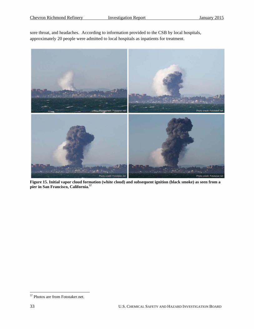
Chevron Richmond Refinery Investigation Report January 2015
33 U.S. CHEMICAL SAFETY AND HAZARD INVESTIGATION BOARD
sore throat, and headaches. According to information provided to the CSB by local hospitals, approximately 20 people were admitted to local hospitals as inpatients for treatment.
Figure 15. Initial vapor cloud formation (white cloud) and subsequent ignition (black smoke) as seen from a pier in San Francisco, California.57
57 Photos are from Fototaker.net.
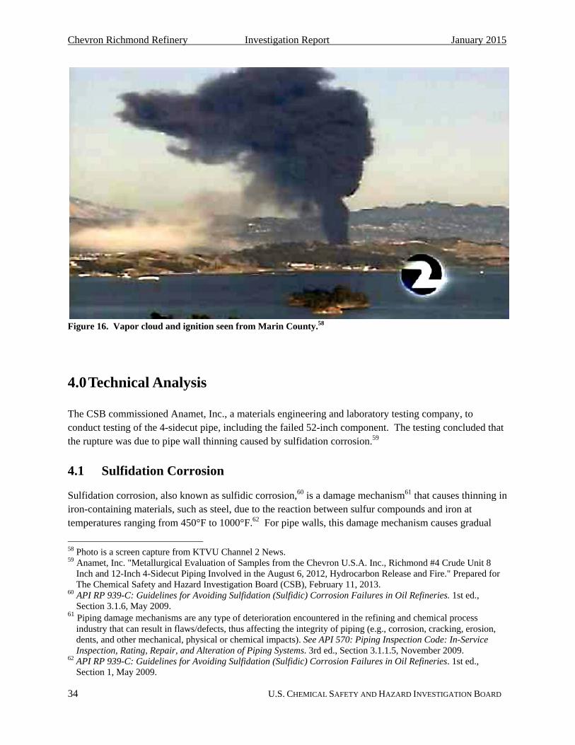
Chevron Richmond Refinery Investigation Report January 2015
34 U.S. CHEMICAL SAFETY AND HAZARD INVESTIGATION BOARD
Figure 16. Vapor cloud and ignition seen from Marin County.58
4.0 Technical Analysis
The CSB commissioned Anamet, Inc., a materials engineering and laboratory testing company, to conduct testing of the 4-sidecut pipe, including the failed 52-inch component. The testing concluded that the rupture was due to pipe wall thinning caused by sulfidation corrosion.59
4.1 Sulfidation Corrosion
Sulfidation corrosion, also known as sulfidic corrosion,60 is a damage mechanism61 that causes thinning in iron-containing materials, such as steel, due to the reaction between sulfur compounds and iron at temperatures ranging from 450°F to 1000°F.62 For pipe walls, this damage mechanism causes gradual
58 Photo is a screen capture from KTVU Channel 2 News. 59 Anamet, Inc. "Metallurgical Evaluation of Samples from the Chevron U.S.A. Inc., Richmond #4 Crude Unit 8
Inch and 12-Inch 4-Sidecut Piping Involved in the August 6, 2012, Hydrocarbon Release and Fire." Prepared for The Chemical Safety and Hazard Investigation Board (CSB), February 11, 2013.
60 API RP 939-C: Guidelines for Avoiding Sulfidation (Sulfidic) Corrosion Failures in Oil Refineries. 1st ed., Section 3.1.6, May 2009.
61 Piping damage mechanisms are any type of deterioration encountered in the refining and chemical process industry that can result in flaws/defects, thus affecting the integrity of piping (e.g., corrosion, cracking, erosion, dents, and other mechanical, physical or chemical impacts). See API 570: Piping Inspection Code: In-Service Inspection, Rating, Repair, and Alteration of Piping Systems. 3rd ed., Section 3.1.1.5, November 2009.
62 API RP 939-C: Guidelines for Avoiding Sulfidation (Sulfidic) Corrosion Failures in Oil Refineries. 1st ed., Section 1, May 2009.

Chevron Richmond Refinery Investigation Report January 2015
35 U.S. CHEMICAL SAFETY AND HAZARD INVESTIGATION BOARD
thinning over time. Sulfidation corrosion is common in crude oil distillation,63 where naturally occurring sulfur and sulfur compounds found in crude oil feed, such as hydrogen sulfide,64 are available to react with steel piping and equipment. Process variables that affect corrosion rates include the total sulfur content of the oil, the sulfur species present, flow conditions, and the temperature of the system. Virtually all crude oil feeds contain sulfur compounds; therefore, sulfidation corrosion is a damage mechanism present at every refinery that processes crude oil. Sulfidation corrosion can cause thinning to the point of pipe failure when not properly monitored and controlled.
Sulfidation corrodes carbon steel at a much faster rate in comparison with its effect on other materials of construction, such as steels with a higher chromium content. This issue is discussed in depth in the CSB’s Interim Investigation Report of the August 6, 2012, Chevron incident.65 In addition to its naturally faster rate of sulfidation corrosion when compared with higher chromium steels, carbon steel can also experience significant variation in corrosion rates due to variances in silicon content, a component used in the steel manufacturing process. Carbon steel piping containing silicon content less than 0.10 weight percent can corrode at accelerated rates,66 up to 16 times faster than carbon steel piping containing higher percentages of silicon. Figure 17 shows how carbon steel corrosion rates can greatly vary depending on silicon content.
63 Distillation separates mixtures into broad categories of its components by heating the mixture in a distillation
column where different products boil off and are recovered at different temperatures. See http://www.eia.gov/todayinenergy/detail.cfm?id=6970 (accessed April 4, 2013).
64 Hydrogen sulfide is the most aggressive sulfur compound that causes sulfidation corrosion. 65 http://www.csb.gov/assets/1/19/Chevron_Interim_Report_Final_2013-04-17.pdf (accessed April 2, 2014). 66API RP 939-C: Guidelines for Avoiding Sulfidation (Sulfidic) Corrosion Failures in Oil Refineries. 1st ed., Section
6.2.3.2, May 2009.

Chevron Richmond Refinery Investigation Report January 2015
36 U.S. CHEMICAL SAFETY AND HAZARD INVESTIGATION BOARD
Figure 17. Graph of sulfidation corrosion rates with respect to silicon content in carbon steel. This graph shows how corrosion rates increase in carbon steel containing decreasing percentages of silicon. This information can be found in Annex C of API RP 939-C.67
The refining industry has been aware of increased susceptibility to sulfidation corrosion in low-silicon carbon steel piping since as early as 1974,68 nearly 40 years before the August 6, 2012, incident and two years before the Chevron Crude Unit was constructed. Before the incident, Chevron documented its understanding of the potentially catastrophic nature of failures caused by sulfidation corrosion, as reflected in Chevron’s Corrosion Prevention and Metallurgy Manual:
Sulfidation corrosion has caused severe fires and fatalities in the refining industry, primarily because it causes corrosion over a relatively large area, so failures tend to involve ruptures or large leaks rather than pinhole leaks. It can be insidious in that moderately high corrosion rates can go undetected for years before failure. Finally, process changes that increase the temperature or sulfur content can creep up over time and multiply corrosion rates so that what was thought to be a low corrosion rate system becomes corrosive enough to fail before the increased corrosion rate is recognized.
67 The y-axis of this figure is in units of mils per year (mpy). A “mil” is 1/1000 inch. 68 API Publication 943: High-Temperature Crude Oil Corrosivity Studies. September 1974.

Chevron Richmond Refinery Investigation Report January 2015
37 U.S. CHEMICAL SAFETY AND HAZARD INVESTIGATION BOARD
Carbon steel piping is manufactured to meet certain specifications. Prior to the mid-1980s, multiple carbon steel specifications were commonly and independently in use for refinery piping, including American Society for Testing and Materials (ASTM) A53B,69 ASTM A106,70 and American Petroleum Institute (API) 5L.71 ASTM A53B and API 5L do not contain minimum silicon content requirements for carbon steel piping,72 while ASTM A106 requires the piping to be manufactured with a minimum silicon content of 0.10 weight percent. As a result, manufacturers have used different levels of silicon in the carbon steel pipe manufacturing process. Thus, depending on the manufacturing specification for carbon steel, sulfidation corrosion rates could vary depending on the silicon content within the steel.
In the mid-1980s, pipe manufacturers began to comply simultaneously with all three manufacturing specifications (ASTM A53B, ASTM A106, and API 5L) when manufacturing carbon steel piping, which resulted in piping being manufactured with at least 0.10 weight percent silicon content due to the ASTM A106 requirement. As a result, the majority of carbon steel piping purchased following this time period for refinery operations likely has a minimum of 0.10 weight percent silicon content. However, piping purchased and installed prior to the mid-1980s could still contain low silicon components susceptible to high, variable sulfidation corrosion rates.
The timing of this manufacturing change has a profound impact on the susceptibility of refineries to variable sulfidation corrosion rates today. Over 95 percent of the 144 refineries in operation in the United States, including the Chevron Richmond Refinery,73 were built before 1985,74 before piping manufacturers began producing carbon steel in compliance with all three manufacturing specifications. Therefore, the original carbon steel piping components in these refineries is likely to contain varying percentages of silicon content and may experience highly variable sulfidation corrosion rates.
The Chevron Richmond Refinery 4-sidecut piping circuit containing the 52-inch component that failed was constructed of ASTM A53B carbon steel, which had no minimum specification for silicon content. Post-incident testing of samples of the 4-sidecut piping from the Chevron Richmond Refinery identified silicon content ranging from 0.01 weight percent to 0.2 weight percent. Of 12 samples taken from the 8-inch and the adjacent 12-inch 4-sidecut line, six had a silicon concentration of less than 0.10 weight percent (Figure 18 and Figure 19). The 52-inch pipe component that ruptured on the day of the incident had a silicon content of only 0.01 weight percent. Illustrating the inherent variability in ASTM A53B carbon steel sulfidation corrosion rates, the elbow component directly upstream of the 52-inch component that failed had a silicon concentration of 0.16 weight percent and showed considerably less thinning (Figure 20).
69 ASTM Standard A53/A53M-12: Standard Specification for Pipe, Steel, Black and Hot-Dipped, Zinc-Coated,
Welded and Seamless, 2012. 70 ASTM Standard A106/A106M–11: Standard Specification for Seamless Carbon Steel Pipe for High-Temperature
Service, 2011. 71 API Specification 5L: Specification for Line Pipe. 45th ed., December 2012. 72 ASTM Standard A53/A53M-12: Standard Specification for Pipe, Steel, Black and Hot-Dipped, Zinc-Coated,
Welded and Seamless, 2012. 73 The Chevron Richmond Refinery was constructed in 1902. 74 See http://www.eia.gov/tools/faqs/faq.cfm?id=29&t=6 (accessed February 14, 2013).

Chevron Richmond Refinery Investigation Report January 2015
38 U.S. CHEMICAL SAFETY AND HAZARD INVESTIGATION BOARD
Figure 18. Locations of metallurgical samples taken from 8-inch 4-sidecut piping post-incident. The seven samples taken are boxed in orange. Four of the seven components sampled (shown with an orange fill) were found to have a silicon content less than 0.10 weight percent.

Chevron Richmond Refinery Investigation Report January 2015
39 U.S. CHEMICAL SAFETY AND HAZARD INVESTIGATION BOARD
Figure 19. Locations of metallurgical samples taken from 12-inch 4-sidecut piping post-incident. The five samples taken are boxed in orange. Two of the five components sampled (shown with an orange fill) were found to have a silicon content less than 0.10 weight percent.

Chevron Richmond Refinery Investigation Report January 2015
40 U.S. CHEMICAL SAFETY AND HAZARD INVESTIGATION BOARD
Figure 20. 4-sidecut piping sample (E-017-8) analyzed by Anamet Labs showing the relative thickness of low silicon piping on the left and the high silicon piping on the right. The ruptured 52-inch pipe component (left) contained 0.01 weight percent silicon, and the upstream elbow component (right) contained 0.16 weight percent silicon.75 The initial nominal thickness of this piping was 0.322-inch.
75 Anamet, Inc. "Metallurgical Evaluation of Samples from the Chevron U.S.A. Inc., Richmond #4 Crude Unit 8-
Inch and 12-Inch 4-Sidecut Piping Involved in the August 6, 2012, Hydrocarbon Release and Fire." Prepared for: The Chemical Safety and Hazard Investigation Board (CSB), February 11, 2013.

Chevron Richmond Refinery Investigation Report January 2015
41 U.S. CHEMICAL SAFETY AND HAZARD INVESTIGATION BOARD
4.2 Sulfidation Corrosion Inspection Techniques
As evidenced by the chemical analysis performed on the Chevron 4-sidecut piping post-incident, carbon steel piping components within a single circuit76 can contain varying percentages of silicon, resulting in a large variation in sulfidation corrosion rates by component. Current corrosion inspection guidance documents allow for the measurement of pipe thickness at a minimal number of permanent Condition Monitoring Locations (CMLs)77 along the piping length.78,79 These CMLs are most frequently placed on elbows and fittings80 because higher turbulence in these areas usually results in the fastest metal loss.81 However, due to details of the manufacturing process, carbon steel elbows and pipe fittings, even when manufactured to the ASTM A53B specification, generally contain relatively high percentages of silicon.82 When measurements are taken only at high silicon-containing fittings, the measurements can fail to identify high corrosion rates within a pipe circuit occurring within low-silicon, straight-run piping components.
API Recommended Practice (RP) 939-C Guidelines for Avoiding Sulfidation (Sulfidic) Corrosion Failures in Oil Refineries describes the challenges when attempting to inspect carbon steel lines susceptible to sulfidation corrosion. The recommended practice states that older ASTM A53B piping, such as the Chevron piping that failed on August 6th, creates a “major inspection challenge”83 and “unless the refinery is fortunate enough to have located an inspection point on that particular [low silicon] section of pipe or fitting, it is very difficult to detect the thinning component.”84 It states that in some applications, carbon steel will appear to be adequate based on measured corrosion rates until failure occurs at some undocumented or unidentified low-silicon component.85
At the Chevron Richmond Refinery, the 8-inch 4-sidecut piping had a total of 19 CMLs86 on piping and fittings. Historically, most of the CMLs measured corrosion rates at high silicon pipe-fitting components, such as elbow components. An effort in 2011 added additional CMLs on straight-run components within
76 A piping circuit is a length of pipe and the fittings associated with a particular process service that operate at
similar conditions. A circuit usually begins and ends at either a branch or a piece of process equipment, such as a vessel or a pump. Reference to piping by circuits allows piping to be grouped conveniently by proximity and operating service. Piping circuits may also be referred to as piping runs.
77 A condition monitoring location (CML) is a designated area where periodic thickness examinations are conducted. Each CML represents as many as four inspection locations located circumferentially around the pipe. CMLs are also referred to as thickness monitoring locations (TMLs). CMLs were historically referred to as corrosion (rather than condition) monitoring locations, and that terminology is sometimes still used within the industry.
78 API 570: Piping Inspection Code: In-service Inspection, Rating, Repair, and Alteration of Piping Systems, 3rd ed., Section 5.6.3, November 2009.
79 For most damage mechanisms that affect an entire piping circuit, the whole circuit loses metal at a similar rate. Monitoring pipe thickness at a minimal number of CMLs is considered representative of the entire pipe.
80 A fitting is a piping component usually associated with a change in direction or diameter. 81 API 570: Piping Inspection Code: In-service Inspection, Rating, Repair, and Alteration of Piping Systems, 3rd
ed., Section 5.6.2, November 2009. 82 API RP 939-C: Guidelines for Avoiding Sulfidation (Sulfidic) Corrosion Failures in Oil Refineries, 1st ed.,
Section 7.1.5, May 2009. 83 Ibid., Section 9. 84 Ibid., Section 7.1.5. 85 Ibid., Section 6.2.3.2. 86 Many of these CMLs were added during the 2011 turnaround.

Chevron Richmond Refinery Investigation Report January 2015
42 U.S. CHEMICAL SAFETY AND HAZARD INVESTIGATION BOARD
the 8-inch 4-sidecut piping circuit, although 100 percent component inspection was not performed. The CSB found that, although a CML was located on the adjacent upstream elbow, no CMLs were placed on the low silicon piping component that failed (Figure 21). Chevron identified corrosion in the 52-inch component during a supplemental 2002 inspection,87 but the inspection results were not entered into the CML-tracking portion of the inspection database, and no new CML was required to be added to ensure future monitoring. As a result, the 52-inch component was never inspected again (Section 5.1.2.1.1).
Figure 21. CML placement on 8-inch 4-sidecut piping. Nineteen CMLs were used to monitor corrosion rates in the 8-inch 4-sidecut piping. A CML was not placed on the 52-inch component that ultimately failed. A CML was placed, however, on the upstream elbow adjacent to the 52-inch component.
This inspection data gathered using the 19 CMLs did not reflect the corrosion rates of the quickly corroding, low-silicon components of the 4-sidecut piping. As illustrated by the Chevron incident, traditional inspection techniques alone—using only a limited amount of CMLs—may not accurately identify the most aggressive sulfidation corrosion rates throughout an entire circuit of carbon steel piping.
87 The inspector was supervising contractors who were conducting measurements on a CML located on the adjacent
elbow. Prompted by a recent Chevron corrosion study, he decided to have them also measure the straight pipe about one foot before and after the elbow, on the other side of the welds, by radiographic thickness techniques (RT). These were not formal CMLs. In 2002, the 52-inch component had lost roughly a third of its original wall thickness. The only documentation of this measurement was a note in a history brief in the inspection database.
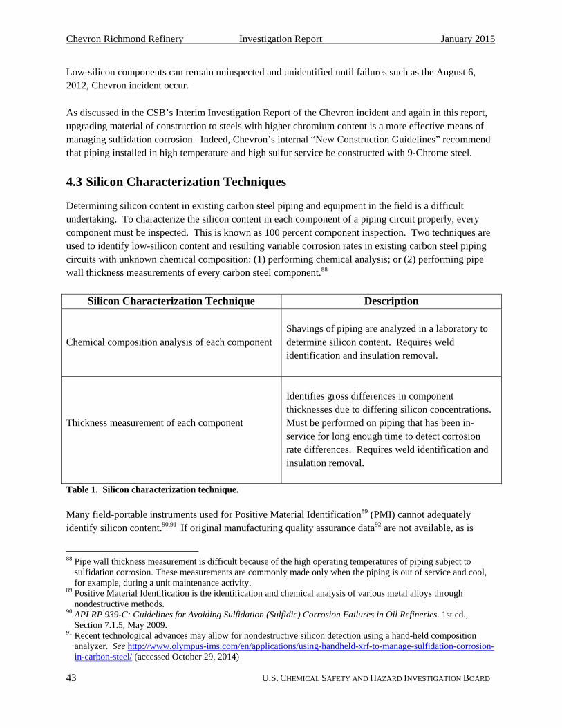
Chevron Richmond Refinery Investigation Report January 2015
43 U.S. CHEMICAL SAFETY AND HAZARD INVESTIGATION BOARD
Low-silicon components can remain uninspected and unidentified until failures such as the August 6, 2012, Chevron incident occur.
As discussed in the CSB’s Interim Investigation Report of the Chevron incident and again in this report, upgrading material of construction to steels with higher chromium content is a more effective means of managing sulfidation corrosion. Indeed, Chevron’s internal “New Construction Guidelines” recommend that piping installed in high temperature and high sulfur service be constructed with 9-Chrome steel.
4.3 Silicon Characterization Techniques
Determining silicon content in existing carbon steel piping and equipment in the field is a difficult undertaking. To characterize the silicon content in each component of a piping circuit properly, every component must be inspected. This is known as 100 percent component inspection. Two techniques are used to identify low-silicon content and resulting variable corrosion rates in existing carbon steel piping circuits with unknown chemical composition: (1) performing chemical analysis; or (2) performing pipe wall thickness measurements of every carbon steel component.88
Silicon Characterization Technique Description
Chemical composition analysis of each component
Shavings of piping are analyzed in a laboratory to determine silicon content. Requires weld identification and insulation removal.
Thickness measurement of each component
Identifies gross differences in component thicknesses due to differing silicon concentrations. Must be performed on piping that has been in-service for long enough time to detect corrosion rate differences. Requires weld identification and insulation removal.
Table 1. Silicon characterization technique.
Many field-portable instruments used for Positive Material Identification89 (PMI) cannot adequately identify silicon content.90,91 If original manufacturing quality assurance data92 are not available, as is
88 Pipe wall thickness measurement is difficult because of the high operating temperatures of piping subject to
sulfidation corrosion. These measurements are commonly made only when the piping is out of service and cool, for example, during a unit maintenance activity.
89 Positive Material Identification is the identification and chemical analysis of various metal alloys through nondestructive methods.
90 API RP 939-C: Guidelines for Avoiding Sulfidation (Sulfidic) Corrosion Failures in Oil Refineries. 1st ed., Section 7.1.5, May 2009.
91 Recent technological advances may allow for nondestructive silicon detection using a hand-held composition analyzer. See http://www.olympus-ims.com/en/applications/using-handheld-xrf-to-manage-sulfidation-corrosion-in-carbon-steel/ (accessed October 29, 2014)
Chevron Richmond Refinery Investigation Report January 2015
44 U.S. CHEMICAL SAFETY AND HAZARD INVESTIGATION BOARD
generally the case with older plants, then chemical verification requires destructive testing. Metal shavings must be taken from each carbon steel piping component for chemical analysis in a laboratory.93 Care must be taken not to contaminate the sample with bits of metal from the tools used to gather the sample.
Carbon steel components containing low concentrations of silicon can also be identified by performing one-time thickness measurements of every component within a carbon steel circuit.94 This practice is only useful as a means to ascertain silicon content if the piping circuit has been exposed to sulfidation corrosion for a long enough time period so that variances in corrosion rate caused by differences in silicon content may be detected. Chemical analysis is, therefore, the most reliable technique to identify low-silicon carbon steel components.
Both characterization techniques require identification of each piping component, typically by removing insulation (so every weld seam can be located), a time consuming and costly undertaking. Weld seams can be located through insulation using specialized equipment and examination techniques, but this method can be less accurate than when weld seams are identified manually. Both silicon characterization techniques can be technically difficult and physically hazardous for inspectors because of the high operating temperatures of piping subject to sulfidation. It is common to make thickness measurements or take shaving samples only when the piping is out of service and cool, for example, during a unit maintenance turnaround.95
Unlike silicon concentration, the chromium concentration of steel can easily be verified in the field using portable positive material identification instruments. In addition, steel alloys containing at least 9 weight percent chromium are more resistant to sulfidation corrosion and do not run the risk of extreme variations in corrosion rates within components in the same piping circuit.96 This makes alloys with at least 9 weight percent chromium content an inherently safer choice97 in high temperature sulfidation corrosion environments because the hazard presented by varying corrosion rates within a single piping circuit is eliminated. As shown in the Modified McConomy Curves98 from API RP 939-C (Figure 22), higher chromium steels are also a better safeguard than carbon steel because sulfidation corrosion rates are
92 Manufacturing quality assurance data, also known as mill data, provides the chemical composition of the steel. 93 API RP 939-C: Guidelines for Avoiding Sulfidation (Sulfidic) Corrosion Failures in Oil Refineries. 1st ed.,
Section 7.1.5, May 2009. 94 Ibid., Section 7.1.5. 95 A “turnaround” is a scheduled shutdown of a process unit to perform maintenance, repairs, upgrades, and
inspection of process equipment. 96 The protective scale, FeCr2S4, begins to be the dominant scale formed in steels containing a chromium content of
five weight percent. The 5Cr steel alloy can be manufactured to contain anywhere from 4 percent to 6 percent chromium. Thus, “the sulfidation corrosion rate can vary dramatically in 5Cr steels even in the same operating environment.” See Niccolls, E. H., J. M. Stankiewicz, J. E. McLaughlin, and K. Yamamoto. "High Temperature Sulfidation Corrosion in Refining." 17th International Corrosion Congress. Las Vegas: NACE International, 2008.
97 Steels with higher chromium content are inherently safer than carbon steel with respect to sulfidation corrosion because they can eliminate the hazard of gross variations in corrosion rates within a single piping circuit. However, analysis is still required to ensure that the best material of construction is selected.
98 Modified McConomy Curves are the set of curves API RP 939-C uses to predict sulfidation corrosion rates versus temperature for several steel alloys.

Chevron Richmond Refinery Investigation Report January 2015
45 U.S. CHEMICAL SAFETY AND HAZARD INVESTIGATION BOARD
greatly reduced. Carbon steel99 corrodes approximately nine times faster than 9-Chrome steel, which contains 9 percent chromium, and carbon steel corrodes approximately 120 times faster than stainless steel, which contains 18 percent chromium.100,101
Figure 22. Modified McConomy Curves from API RP 939-C.
4.4 Inherently Safer Design
Efforts to improve chemical process safety require the identification of process hazards, followed by the elimination, mitigation, or control of process hazards to reduce the overall risk of a process. A hazard can be defined as a “situation with the potential for harm.” Risk is then defined as a function of both the consequence (hazard) and likelihood (frequency).102
Risk reduction can be achieved by using, in order of robustness, inherently safer design, passive safeguards, active safeguards, and procedural safeguards.103 This can be thought of as a tiered or hierarchical approach to risk management, commonly referred to as a “hierarchy of controls.” The further
99 ASTM A53B carbon steel contains a maximum of 0.40 weight percent chromium. 100 9-Chrome contains 9 weight percent chromium. 101 These values were calculated using the McConomy Curves at 630°F. 102 Center for Chemical Process Safety (CCPS). Inherently Safer Chemical Processes – A Life Cycle Approach. 2nd ed., Section 2.1, 2009. 103 Ibid.
100.0

Chevron Richmond Refinery Investigation Report January 2015
46 U.S. CHEMICAL SAFETY AND HAZARD INVESTIGATION BOARD
up the hierarchy, the more effective the risk reduction achieved (Figure 23). Inherently safer design104 reduces risk by permanently reducing or eliminating a defined hazard itself, while safeguards defined as passive (design features), active (detection and automatic response), and procedural (policies, procedures, training, inspection, use of personal protective equipment) reduce risk by reducing the ultimate consequence or likelihood of the hazard.105
Figure 23. Hierarchy of controls. The further up the hierarchy (further to the left as shown here), the more effective the risk reduction achieved. Figure developed from concept presented in Kletz, Trevor; Amyotte, Paul. Process Plants: A Handbook for Inherently Safer Design, 2nd ed; 2010.
These definitions are published by the Center for Chemical Process Safety (CCPS), a not-for-profit corporate membership organization within the American Institute of Chemical Engineers that identifies and addresses process safety needs within the chemical, pharmaceutical, and petroleum industries.106 The CCPS book Inherently Safer Chemical Processes, 2nd ed. designates a process as inherently safer “if it reduces or eliminates the hazards associated with materials and operations used in the process and this reduction or elimination is permanent and inseparable.”107 A facility can approach its inherently safer design strategy by looking for opportunities to minimize, substitute, moderate, or simplify.108
The August 6, 2012, sulfidation corrosion pipe rupture at the Chevron Richmond Refinery highlights a missed opportunity to incorporate inherently safer design strategies through the use of more robust materials of construction. CCPS states:
The concept of inherent robustness … applies to designing equipment to be impervious to the corrosion mechanisms that are present given the materials of construction and within the process, and the operating conditions (i.e., temperature, pH, concentration, viscosity, etc.). The use of certain alloys will eliminate certain types of corrosive attack. […] Although robust equipment design may be considered to be a passive safeguard rather than an inherently safer design, it considerably simplifies the remainder of the process design. Therefore, it fits within the definition of simplification [an inherently safer design strategy]. It is also highly effective in eliminating the possibility of an uncontrolled loss
104 The concept of “inherently safer design” was first established by Trevor Kletz in 1977 in response to the 1974
Flixborough explosion in England. He presented a lecture titled “What You Don’t Have, Can’t Leak” at the Jubilee Lecture for the Society of Chemical Industry.
105 Center for Chemical Process Safety (CCPS). Inherently Safer Chemical Processes – A Life Cycle Approach. 2nd ed., Section 2.1, 2009.
106 www.aiche.org/ccps/about (accessed February 14, 2013). 107 Center for Chemical Process Safety (CCPS). Inherently Safer Chemical Processes – A Life Cycle Approach. 2nd
ed., Section 2.2, 2009. 108 bid., Section 3.5.
Chevron Richmond Refinery Investigation Report January 2015
47 U.S. CHEMICAL SAFETY AND HAZARD INVESTIGATION BOARD
of containment. In a general sense, the removal of this possibility from a process design must be considered to be inherently safer.109
Thus, the use of a higher chromium steel alloy, such as 9-Chrome, is an inherently safer design strategy that could have prevented the Chevron Richmond Refinery pipe rupture. Installation of 9-Chrome piping during turnaround opportunities prior to the August 6, 2012, incident to replace the 4-sidecut carbon steel would have both eliminated the hazard of silicon-based variable corrosion rates within the components of the 4-sidecut piping circuit and at the same time also greatly reduced the underlying inherent rate of sulfidation corrosion. The use of 9-Chrome steel also simplifies the procedural inspection safeguards required, as 100 percent component inspection would not be required to monitor corrosion rates in steels containing at least 9 percent chromium; the typical inspection strategy of monitoring corrosion rates using a minimal amount of CMLs would be sufficient.
It is important to remember that inherently safer design strategies are relative; a specific design can only be described as inherently safer when compared to a different design with regard to a specific hazard or risk.110 A design may be inherently safer by eliminating one hazard, but can inadvertently introduce or aggravate another hazard.111 For this reason, performing a comprehensive, documented hazard analysis is vital for identifying the individual hazards and the likelihood of those hazards occurring, followed by identifying how they can be effectively controlled to minimize overall risk. The review should include risks of personal injury, environmental harm, and lost production, as well as evaluating economic feasibility.112 An inherently safer systems review incorporated as an integral part of this hazard analysis generates an optimized list of hazard control choices, offering various degrees of inherently safer design strategies.
Effectively implementing inherently safer design provides an opportunity for preventing major chemical incidents. The August 6, 2012, incident at Chevron and other incidents113 throughout the refining industry highlight the difficulty in preventing failure caused by sulfidation corrosion in low silicon carbon steel piping solely through inspection—a procedural safeguard that is thus among the least effective on the hierarchy of controls. Implementing inherently safer design concepts to the greatest extent feasible by Chevron and other refiners and chemical plant operators will avoid hazards such as variation in sulfidation corrosion rate in carbon steel piping due to hard-to-determine silicon content, and it will provide a higher degree of protection from incidents similar to the one that occurred on August 6, 2012.
109 Center for Chemical Process Safety (CCPS). Inherently Safer Chemical Processes – A Life Cycle Approach. 2nd
ed., Section 4.5.1, 2009. 110 Center for Chemical Process Safety (CCPS). Guidelines for Engineering Design for Process Safety. 2nd ed.,
Section 5.2, 2012. 111 Center for Chemical Process Safety (CCPS). Inherently Safer Chemical Processes – A Life Cycle Approach. 2nd
ed., Section 3.6, 2009. 112 Ibid., Section 8.6.4. 113 API RP 939-C: Guidelines for Avoiding Sulfidation (Sulfidic) Corrosion Failures in Oil Refineries. 1st ed., May
2009.

Chevron Richmond Refinery Investigation Report January 2015
48 U.S. CHEMICAL SAFETY AND HAZARD INVESTIGATION BOARD
5.0 Incident Analysis
The CSB investigation team developed an accident map (AcciMap)114 for the Chevron investigation (Figure 24). The AcciMap is a multilayered causal diagram that depicts immediate causes115 as well as higher level contributing causes at the corporate, governmental, and regulatory levels. This diagram includes five levels:
1. Outcomes: the impact of the August 6, 2012, event to workers present and the surrounding community;
2. Physical Events and Conditions: the immediate causes of the incident as displayed in a traditional logic tree;
3. Chevron: company rules and policies; conduct of turnarounds; risk management; identification of hazards and evaluation of safeguards; adoption of internal recommendations; safety programs; and emergency response;
4. Industry Codes and Standards: good practice guidelines that provide safety requirements and recommendations on topics including mechanical integrity and emergency response; and
5. Government: laws and legislation developed to regulate process safety at refineries.
Some of these contributing factors are discussed in the Chevron Interim Report and the Chevron Regulatory Report. Refer to the AcciMap in Figure 24116 as a guide to locating information.
114 The AcciMap was originally developed by Jens Rasmussen in the article Rasmussen, Jens. “Risk Management in
a Dynamic Society: A Modelling Problem.” Safety Science. Vol. 27, No 2/3, 1997; pp. 183-213. The AcciMap was subsequently used and popularized by Andrew Hopkins, in Hopkins, Andrew. “Lessons From Longford: The Esso Gas Plant Explosion.” CCH Australia Limited: Sydney, 2000; Chapter 10.
115 Immediate causes are the events or conditions that lead directly to an incident, such as mechanical failure or human error.
116 A high-resolution graphic of the AcciMap can be found on the CSB website.

Chevron Richmond Refinery Investigation Report January 2015
49 U.S. CHEMICAL SAFETY AND HAZARD INVESTIGATION BOARD
Figure 24. Acci-Map of August 6, 2012, Chevron Refinery Fire.

Chevron Richmond Refinery Investigation Report January 2015
50 U.S. CHEMICAL SAFETY AND HAZARD INVESTIGATION BOARD
5.1 Organizational Analysis
In the ten years prior to the incident, a small number of Chevron personnel with knowledge and understanding of sulfidation corrosion made recommendations to increase inspections or upgrade the material of construction in the 4-sidecut piping. Their recommendations were not effectively implemented. The process to implement important, safety-critical projects within the Chevron Richmond Refinery was not fully effective. As discussed in the following sections and depicted in Figure 25, a combination of (1) reliance on a turnaround management program that depended on only a fraction of necessary data to make important process safety decisions, (2) an unsuccessful bottom-up approach—with no management oversight or accountability—for implementing a crucial safety program, and (3) no formal method to track to completion the Chevron expert group’s findings and recommendations ultimately caused these recommendations to not be implemented.
Figure 25. Organizational decision-making schematic showing attempts to have carbon steel 4-sidecut piping 100 percent component inspected or replaced with a higher chromium steel alloy. Attempts failed due to lack of accountability and lack of authority to ensure recommendation implementation, and a rigid turnaround planning process that could not approve the 4-sidecut piping replacement recommendations.
Figure 26 shows the sequence of sulfidation corrosion-related recommendations and events within Chevron Corporation and the Chevron Richmond Refinery between 2002 and the day of the incident. These events are discussed in subsequent sections of this report.

Chevron Richmond Refinery Investigation Report January 2015
51 U.S. CHEMICAL SAFETY AND HAZARD INVESTIGATION BOARD
Figure 26. Key events at the Richmond refinery between 2002 and 2012.
The following sections discuss Chevron programs designed to improve equipment reliability and process safety. These programs are summarized in Figure 27 and Figure 28.

Chevron Richmond Refinery Investigation Report January 2015
52 U.S. CHEMICAL SAFETY AND HAZARD INVESTIGATION BOARD
Figure 27. Chevron Corporation refinery process safety programs.

Chevron Richmond Refinery Investigation Report January 2015
53 U.S. CHEMICAL SAFETY AND HAZARD INVESTIGATION BOARD
5.1.1 Chevron Energy Technology Company
In this section:
Within Chevron is a separate business unit called the Chevron Energy Technology Company (ETC). This unit provides technology solutions and technical expertise for Chevron operations worldwide (Figure 28). Chevron ETC technical staff has considerable knowledge and expertise regarding sulfidation corrosion, specifically with respect to corrosion rate variations caused by differing silicon concentration in carbon steel piping. Chevron ETC employees have authored industry papers on sulfidation corrosion and had significant influence in the development of the industry sulfidation corrosion recommended practice, API RP 939-C. This recommended practice, first published in 2009,117 was developed under Chevron leadership. Metallurgists within ETC had shared their knowledge on sulfidation corrosion via many outlets over the years to employees at Chevron refineries, as discussed in the following sections. Despite all of this institutional expertise, the 4-sidecut line ruptured due to sulfidation corrosion at the Chevron Richmond Refinery.
117 As of January 2015, the 2009 edition of API RP 939-C is the active edition of this standard.

Chevron Richmond Refinery Investigation Report January 2015
54 U.S. CHEMICAL SAFETY AND HAZARD INVESTIGATION BOARD
Figure 28. Chevron Energy Technology Company (ETC) organizational roles. ETC provides technology solutions and technical expertise throughout all Chevron (and affiliated companies) operations.
5.1.1.1 ETC Sulfidation Failure Prevention Guidance
At the approximate time of publication of API RP 939-C, Chevron ETC metallurgists released within Chevron a formal report dated September 30, 2009, nearly three years before the incident, titled Updated Inspection Strategies for Preventing Sulfidation Corrosion Failures in Chevron Refineries (hereinafter referred to as ETC Sulfidation Failure Prevention Initiative).
The ETC Sulfidation Failure Prevention Initiative clearly indicates that Chevron technical experts understood the high likelihood that the consequence of a sulfidation corrosion failure could be a rupture or catastrophic failure. It specifically calls out Chevron’s need for action:
Sulfidation corrosion failures are not common in Chevron or in the industry but they are of great concern because of the comparatively high likelihood of blowout or catastrophic failure…. This can happen because corrosion occurs at a relatively uniform rate over a broad area so a pipe can get progressively thinner until it actually bursts rather than leaking at a pit or local thin area. In addition the process fluid is often above its autoignition temperature. The combination of these factors means that sulfidation corrosion failures frequently result in large fires.… [S]everal case histories of sulfidation corrosion failures … have occurred in Chevron or in the industry, several of which are blowouts.
The Chevron ETC Sulfidation Failure Prevention Initiative specifically recommends that inspectors perform 100 percent component inspection on high temperature carbon steel piping susceptible to sulfidation corrosion. The initiative defines a priority ranking system to help focus the inspection efforts. The process conditions of the 4-sidecut stream—operating temperatures greater than 600°F— placed it in the highest priority category for inspection.
In 2010, Chevron ETC technical experts issued a corporate newsletter focusing on materials and corrosion, again warning of the potential consequence of sulfidation failures. This newsletter reiterated

Chevron Richmond Refinery Investigation Report January 2015
55 U.S. CHEMICAL SAFETY AND HAZARD INVESTIGATION BOARD
the recommendation from the 2009 ETC Sulfidation Failure Prevention Initiative to conduct 100 percent component inspection of carbon steel piping systems that operated over 600°F. The Richmond Crude Unit 4-sidecut piping fell within this high-priority inspection category. This newsletter was accessible to all employees on Chevron’s company intranet.
Chevron ETC also regularly hosted training sessions for refinery personnel. One of these classes, designed for refinery inspection staff but also attended by refinery engineers and senior operators, focused specifically on crude units and on corrosion mechanisms within crude units—including sulfidation corrosion. One of the main messages from this training was that sulfidation corrosion in piping containing low-silicon components can result in catastrophic rupture, and that the means to prevent rupture from occurring is performing 100 percent component inspection or upgrading to a higher chromium steel (Figure 29 and Figure 30).
Figure 29. Presentation slide of ETC training course that guided refinery staff to perform 100 percent component inspection on high-temperature lines susceptible to sulfidation corrosion.

Chevron Richmond Refinery Investigation Report January 2015
56 U.S. CHEMICAL SAFETY AND HAZARD INVESTIGATION BOARD
Figure 30. Presentation slide of ETC training course that guided refinery staff on ways to reduce risk from sulfidation corrosion.
The 2009 ETC Sulfidation Failure Prevention Initiative report was circulated to reliability managers and metallurgists at the individual refineries, as well as to the corporate reliability expert. The authors of the Chevron ETC report chose to send the report to these individuals specifically because they seemed to be the right people to perform and advocate for the necessary inspection and replacement work. However, the CSB discovered that the Reliability Department at the Chevron Richmond Refinery believed that the 100 percent component inspection initiative recommended by the ETC sulfidation failure prevention guidance, while important safety work, was an ambitious, unfunded, and unsupported initiative which could not be effectively performed solely within the normal budget and headcount resources of the Reliability group. Also, the Reliability group made attempts to forego the burdensome inspection initiative and simply implement the ETC alternative sulfidation mitigation strategy to improve sulfidation corrosion resistance through using higher chromium steel by recommending replacement of the 8-inch 4-sidecut piping with inherently safer higher chromium steel.118 However, these recommendations were denied on multiple occasions during the Chevron turnaround planning process (Section 5.1.2). As discussed in the following sections, the Chevron programs created to ensure that necessary work was performed to maintain reliable, safe operation and corporate-wide process safety were not successful in preventing the rupture that had the potential to seriously harm 19 Chevron employees on August 6, 2012.
5.1.1.2 Chevron ETC Conclusions
Despite many attempts by Chevron ETC to warn and educate refinery personnel, neither 100 percent component inspection of high-risk carbon steel piping nor upgrading susceptible piping to an inherently safer material of construction was fully performed at the Chevron Richmond Refinery. In practical terms, because Chevron ETC was a separate business entity within the Chevron corporation and had no direct authority over the reliability management within the Chevron refineries, Chevron ETC sulfidation corrosion experts had limited influence on what actually occurred within refineries in their areas of expertise. These individuals did not participate in refinery-specific processes such as Process Hazard
118 Shown in Figure 30, ETC’s senior inspector and analysis training taught inspectors that sulfidation corrosion
resistance could be improved by upgrading susceptible piping circuits to steels containing higher percentages of chromium.

Chevron Richmond Refinery Investigation Report January 2015
57 U.S. CHEMICAL SAFETY AND HAZARD INVESTIGATION BOARD
Analyses (PHAs)119 (see Chevron Interim Investigation Report) and did not affect decisions concerning monitoring and control of sulfidation corrosion during the Crude Unit turnaround process (Section 5.1.2).
No formal system is in place at the Chevron Richmond Refinery to communicate to the refinery management and to track to completion ETC findings and recommendations. While Chevron does use an indicators tracking program (Section 5.1.6), the program does not measure the implementation status of ETC recommendations and new industry guidance determined by Chevron technical experts to be critical in ensuring continued safe operations at Chevron refineries.
119 A process hazard analysis is a hazard evaluation to identify, evaluate, and control the hazards involved in a
process. Facilities that process a threshold quantity of hazardous materials, such as the Chevron Richmond refinery, are required to conduct a process hazard analysis per the California Code of Regulations Title 8 Section 5189. Process Safety Management of Acutely Hazardous Materials (1992). PHAs are also required by the California Accidental Release Prevention Program and the federal EPA Risk Management Program. See the CSB’s Chevron Interim Investigation Report for a full analysis on this subject.

Chevron Richmond Refinery Investigation Report January 2015
58 U.S. CHEMICAL SAFETY AND HAZARD INVESTIGATION BOARD
5.1.2 Chevron Turnaround Management
In this section:
Chevron uses a turnaround planning and implementation process called Initiative for Managing Pacesetter Turnarounds, known within Chevron as the IMPACT process. It is organized into several different phases, each with a specific objective. The IMPACT process begins several years before each scheduled turnaround. Chevron’s stated goal of the IMPACT process is to perform turnarounds efficiently and effectively, ensuring that only the necessary work items that must be performed during the turnaround are performed, and all other items that can be performed on-the-run (while the unit is operating) or during the next turnaround are not included in the work scope. The turnaround work approval process is guided by what Chevron calls a “Framing Document.” It is developed over a year before the planned turnaround, by a group including turnaround planning management, a decision review board, and specific process unit managers. An IMPACT “Core Team” comprised of an operations representative, inspector, design engineer, process engineer, capital project representative, and maintenance representative are the main decision makers regarding what potential work items meet the requirements of the Framing Document and thus have the potential to be automatically included in the turnaround. The work items that pass the

Chevron Richmond Refinery Investigation Report January 2015
59 U.S. CHEMICAL SAFETY AND HAZARD INVESTIGATION BOARD
Framing Document test are then prioritized.120 A group of refinery managers determine a priority cutoff, and only items in this high-priority, Framing Document-approved list are automatically included in the turnaround scope. The items below the priority cutoff are reviewed by refinery managers and can be included in the turnaround scope on a case-by-case basis. The Core Team follows the strict criteria described in the turnaround Framing Document when approving or denying requested turnaround work submitted by refinery employees. If the Core Team determines that a potential work item does not meet the Framing Document requirements, it never reaches the prioritization step, so it is not part of a review by the refinery managers.
5.1.2.1 2007 Crude Unit Turnaround
The Framing Document used for the 2007 Crude Unit turnaround specified that the primary requirements for the turnaround included performing any work needed to assure a minimum of 10 years (two turnaround cycles) before the next inspection or maintenance was required, performing all required compliance inspections, and recertifying state operating permits for boilers. The detailed work list criteria for the turnaround are shown in Figure 31.
120 The prioritization was based on a combined severity and likelihood of impacts in four individually-weighted
categories: health, safety, environmental, and production. The higher the sum of these four values, the higher the priority for the potential work item.
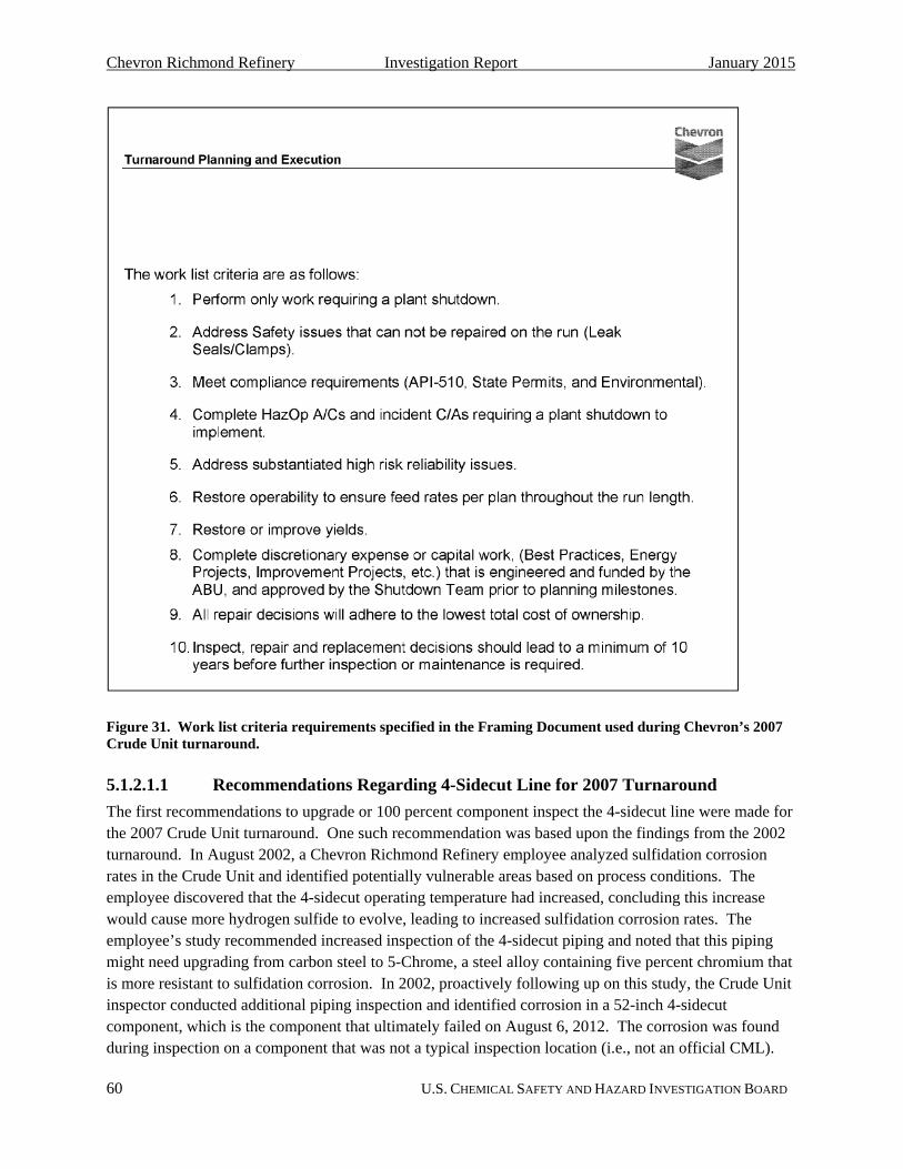
Chevron Richmond Refinery Investigation Report January 2015
60 U.S. CHEMICAL SAFETY AND HAZARD INVESTIGATION BOARD
Figure 31. Work list criteria requirements specified in the Framing Document used during Chevron’s 2007 Crude Unit turnaround.
5.1.2.1.1 Recommendations Regarding 4-Sidecut Line for 2007 Turnaround
The first recommendations to upgrade or 100 percent component inspect the 4-sidecut line were made for the 2007 Crude Unit turnaround. One such recommendation was based upon the findings from the 2002 turnaround. In August 2002, a Chevron Richmond Refinery employee analyzed sulfidation corrosion rates in the Crude Unit and identified potentially vulnerable areas based on process conditions. The employee discovered that the 4-sidecut operating temperature had increased, concluding this increase would cause more hydrogen sulfide to evolve, leading to increased sulfidation corrosion rates. The employee’s study recommended increased inspection of the 4-sidecut piping and noted that this piping might need upgrading from carbon steel to 5-Chrome, a steel alloy containing five percent chromium that is more resistant to sulfidation corrosion. In 2002, proactively following up on this study, the Crude Unit inspector conducted additional piping inspection and identified corrosion in a 52-inch 4-sidecut component, which is the component that ultimately failed on August 6, 2012. The corrosion was found during inspection on a component that was not a typical inspection location (i.e., not an official CML).

Chevron Richmond Refinery Investigation Report January 2015
61 U.S. CHEMICAL SAFETY AND HAZARD INVESTIGATION BOARD
Chevron inspection guidelines require that findings from additional discretionary inspection must be recorded only as notes in a “history brief” rather than input in the inspection database as is typically done for CMLs. Therefore, documentation of the corrosion identified in 2002 was recorded only as notes and was not formally input as data into the inspection database of permanent CML measurements. (An example of inspection database data appears in Figure 32.) The inspector formally recommended upgrading this piping during the next shutdown in 2007 to the IMPACT core team. API does not require new CMLs to be established on components with non-uniform corrosion in potentially low silicon carbon steel piping circuits. Such a requirement in API RP 939-C would help to ensure that components experiencing non-uniform corrosion are effectively monitored, managed, and replaced to prevent sulfidation corrosion failures.
Figure 32. Sample Inspection Database report analyzed by unit inspectors when determining piping remaining life and when making piping replacement recommendations. This Inspection Database report is also analyzed by the IMPACT core team to determine Framing Document applicability.
Adhering to the Chevron turnaround work scope procedures, the IMPACT core team analyzed the available inspection data of the 4-sidecut line from the inspection database to determine whether upgrading the 4-sidecut piping met the Framing Document requirements. The recommendation to upgrade the 4-sidecut piping did not meet the 2007 turnaround Framing Document requirement #10, as all

Chevron Richmond Refinery Investigation Report January 2015
62 U.S. CHEMICAL SAFETY AND HAZARD INVESTIGATION BOARD
recorded data in the inspection database (from existing CMLs on relatively high-silicon piping fittings) indicated that the 4-sidecut piping upstream of the pumps had sufficient thickness to continue to safely operate until the next turnaround before requiring further inspection or maintenance. The recommendation to upgrade the 4-sidecut piping also did not meet the 2007 turnaround Framing Document requirement #5, as the IMPACT core team believed it was not a substantiated high-risk reliability issue because existing inspection data did not indicate an imminent reliability problem. It was determined, however, that the 4-sidecut piping downstream of the pumps required replacement,121 based on the same process of analysis, and only that piping was replaced with an upgraded, inherently safer material of construction, 9-Chrome (Figure 33). Also prior to the 2007 turnaround in February 2006, a team consisting of a materials and corrosion engineer, an inspector, a process engineer, a metallurgist, and a design engineer issued a Corrosion Mitigation Plan for the Chevron Richmond Refinery Crude Unit. This report was developed specifically for the Area Business Unit (ABU) Manager, the highest ranking manager for the Crude Unit. The report specifically identified the 4-sidecut piping to be at risk from high temperature sulfidation corrosion. The team issued the following recommendation:
Recommendation – Install Guided Wave bracelets [on the 4-sidecut piping] during the [2007 Crude Unit] Turnaround so that 100% volumetric inspection of the line can be done to ensure that there are no piping sections in the line that are corroding faster than the majority of the line…. [The] piping needs to be monitored in anticipation of future replacement and additionally, industry experience shows that sections of piping with low silica [sic] content will corrode at higher rates. Monitoring this section of line using global inspection technique like guided wave is the fastest way to determine if there are thin piping pups in the system.
121 The piping downstream of the pumps operates at a higher pressure, and thus the Minimum Required Thickness
calculated was thicker than for the piping on the suction side of the pumps.

Chevron Richmond Refinery Investigation Report January 2015
63 U.S. CHEMICAL SAFETY AND HAZARD INVESTIGATION BOARD
Figure 33. Crude column schematic indicating the piping downstream of the 4-sidecut pumps that was replaced during the 2007 Crude Unit turnaround. The portion of the carbon steel line containing the component that failed on August 6, 2012 was not replaced.
The recommendation to perform 100 percent volumetric inspection through the use of experimental guided wave technology was accepted and implemented by the ABU Manager. 122 The inspection recommendation met the framing document requirement #5 and requirement #8, as it was specified to be based upon past industry sulfidation experience and was approved by the ABU Manager. However, this recommendation was only partially implemented. The guided wave bracelets were installed only on a small portion of the 4-sidecut line, which did not include the 52-inch component that ultimately failed on
122 Common volumetric inspection techniques include ultrasonic and radiography testing.

Chevron Richmond Refinery Investigation Report January 2015
64 U.S. CHEMICAL SAFETY AND HAZARD INVESTIGATION BOARD
August 6, 2012.123 Furthermore, when the experimental guided wave bracelet data proved to be unreliable, manual 100 percent component inspection was not implemented to address the low-silicon piping component corrosion concerns raised in the February 2006 recommendation. In addition, because the Crude Unit inspector’s discretionary inspection observations were not input into the CML-tracking portion of the inspection database as an official CML (discussed earlier in this section), the 52-inch component in which the inspector identified corrosion in 2002—the component that failed on August 6, 2012—was never inspected again.
5.1.2.2 2011 Crude Unit Turnaround
The Framing Document for the 2011 Crude Unit Turnaround states that some of the goals of the 2011 turnaround were to perform work to ensure a five year run; perform compliance inspections and requirements; and perform safety, environmental, and process improvement work that required a shutdown. The work list criteria requirements for the turnaround appear in Figure 34.
Figure 34. Work list criteria requirements specified in the Framing Document used during Chevron’s 2011 Crude Unit turnaround.
123 It was later determined that the guided wave data was unreliable, so the Crude Unit inspector resumed
inspections using ultrasonic thickness measurements.

Chevron Richmond Refinery Investigation Report January 2015
65 U.S. CHEMICAL SAFETY AND HAZARD INVESTIGATION BOARD
A key change from the 2007 Framing Document directly affected whether work items such as 100 percent component inspection or replacement of the 4-sidecut could obtain Core Team approval. In 2007, the Core Team could approve a work item as meeting 2007 Framing Document criterion #10 for inspection, repair or replacement of equipment or piping if it was needed to ensure a minimum of 10 years (two turnaround cycles) before the next inspection or if maintenance was required. The guided wave inspection devices on the 4-sidecut met this criteria. In 2011, this Framing Document criterion was deleted. The Core Team in 2011 should refuse any work item for inspection, repair, or replacement of equipment or piping unless it required a rate cut or shutdown within only 5 years, before the next turnaround (items #2 and #6).
5.1.2.2.1 Recommendations Regarding 4-Sidecut Line for 2011 Turnaround
Following the release of the Chevron ETC Sulfidation Failure Prevention Initiative report, discussed in Section 5.1.1, the Chevron Richmond Refinery materials group completed the risk-ranking of the carbon steel piping in the Richmond Lube Oil Project Unit (RLOP) and in the Crude Unit, two units with high temperature piping known to be susceptible to sulfidation corrosion. The group identified the Crude Unit 4-sidecut line as a high-risk line based on the report ranking guidance. Instead of requesting funding to perform the 100 percent component inspection, the group recommended the 4-sidecut for replacement with 9-Chrome. Just as when planning for the 2007 turnaround, the IMPACT team denied the recommendation because the inspection data available for the 4-sidecut piping did not support a material upgrade during the 2011 turnaround. The IMPACT team did not consider the lack of data on potentially more susceptible 4-sidecut straight-run pipe components.
Chevron also conducts “Intensive Process Reviews” prior to turnarounds. This process involves knowledgeable individuals including Business Improvement Network leaders, process engineers, metallurgical engineers, design engineers, and turnaround planners. The review aims to identify key unit issues that should be addressed and repaired during the unit turnaround. Before the 2011 Crude Unit turnaround, Chevron personnel conducted an Intensive Process Review of the Crude Unit and specifically recommended that the 4-sidecut carbon steel piping “should be upgraded to [5-Chrome] […] due to sulfidation.” Although the Intensive Process Review identified sulfidation problems in the 4-sidecut line, this activity was ineffective. The 4-sidecut piping was not upgraded during the 2011 Crude Unit turnaround because the IMPACT core team determined that it did not meet the turnaround framing document requirements.
During the 2011 turnaround, a portion of the 12-inch 4-sidecut piping was identified as unacceptably thin and was replaced. The 12-inch 4-sidecut piping was the same age, material of construction, and contained the same process fluid with similar process conditions124 as the 8-inch 4-sidecut piping. However, because Chevron relies on existing data to make equipment replacement decisions, employees did not consider that these significant sulfidation corrosion findings could be indicative of similar thinning that could be occurring in the 8-inch piping. This was another missed opportunity during the 2011 Crude Unit turnaround to identify that the 8-inch 4-sidecut piping needed replacement.
124 The CSB notes that the process conditions of the 8-inch and 12-inch 4-sidecut piping were not identical.

Chevron Richmond Refinery Investigation Report January 2015
66 U.S. CHEMICAL SAFETY AND HAZARD INVESTIGATION BOARD
5.1.2.3 Chevron Richmond Refinery Turnaround-Planning Conclusions
There were no 4-sidecut line inspection data indicating that the 8-inch 4-sidecut piping had thinned significantly enough from sulfidation corrosion to require replacement of the piping. Rather, the limited CML data, extrapolated to apply to the entire pipe, including the portion containing the component that failed on August 6, 2012, indicated that the pipe could remain in service until the 2016 turnaround. This oversight occurred for two reasons: (1) 100 percent component inspection was never performed, and (2) recorded data existed only on high-silicon components that corroded at much slower rates than the low-silicon 52-inch component.
Chevron’s data-driven turnaround management framework led to unintended negative consequences. The current Chevron Richmond Refinery turnaround planning framework denies potential, discretionary turnaround work that does not yet have hard data gathered from refinery equipment to support it, even if the work request is based upon guidance issued by the industry trade association, American Petroleum Institute. This rejection is true even if, as in the case of 100 percent component inspection for sulfidation damage, the purpose of the work request is to actually generate the hard data. The only way a Chevron employee can have a work request approved based solely on industry guidance is to appeal to the ABU Manager for the work as an exception to the turnaround framing document criteria. (See 2007 turnaround Framing Document work criteria #8 and 2011 turnaround Framing Document work criteria #9.)
The CSB cannot conclusively state whether even this method would have resulted in the approval to replace the 4-sidecut line, but Chevron reliability and metallurgical staff never attempted it. These individuals had not previously been in the position of having to convince management of the importance of their turnaround work recommendations, so advocating the Sulfidation Failure Prevention Initiative and persuading upper management to implement the ETC recommendations would be a foreign work area for them. In addition, no high-level manager was assigned responsibility to ensure that the ETC Sulfidation Failure Prevention Initiative or other ETC sulfidation recommendations were included in the turnaround scope. As a result, lower level employees who did not have decision-making or funding authority were burdened with convincing Chevron Richmond Refinery management to implement new industry guidance and the ETC recommendations.
The requirement for hard data to justify turnaround work even affected decisions to mitigate hazards identified during a turnaround. During the 2011 turnaround, thinning from sulfidation corrosion in the 12-inch portion of the 4-sidecut piping was found to be so severe that the 12-inch piping had to be replaced immediately. Yet, Chevron replaced only the portions where hard data was available on the specific pipe to support the replacement. The hazardous condition did not prompt Chevron turnaround management to inspect all of the 4-sidecut piping or to preemptively implement the longstanding recommendation to replace all of the carbon steel portions.
Post-incident, Chevron performed 100 percent component inspection of all Chevron Richmond Refinery Crude Unit piping susceptible to sulfidation corrosion. Four carbon steel piping components out of the 4,600 components inspected were identified to have higher corrosion rates than adjacent piping.125 Each
125 Steve Wildman (Chevron) letter to Randall Sawyer (Contra Costa Health Services), April 12, 2013.
http://www.ci.richmond.ca.us/DocumentCenter/View/26802 (accessed June 30, 2014).

Chevron Richmond Refinery Investigation Report January 2015
67 U.S. CHEMICAL SAFETY AND HAZARD INVESTIGATION BOARD
of these four piping segments of which Chevron was unaware might have ultimately failed like the 52-inch 4-sidecut segment. This inspection activity may have prevented additional pipe ruptures in the unit due to accelerated sulfidation corrosion in low-silicon carbon steel.

Chevron Richmond Refinery Investigation Report January 2015
68 U.S. CHEMICAL SAFETY AND HAZARD INVESTIGATION BOARD
5.1.3 Chevron Unit Reliability Improvement Process
In this section:
Chevron’s Unit Reliability Improvement Process (URIP) formally integrates a broad range of reliability activities. This program applies to all of Chevron’s wholly owned refineries. The overall URIP consists of several sub-processes, including Reliability in Asset Integrity, Resolution of Significant Reliability Opportunities, Risk Assessment and Asset Strategy, Condition Monitoring and Surveillance, Proactive Maintenance, and Maintenance and Failure Prevention.
Beginning in 2009 as part of the URIP process, Chevron refineries began holding monthly Unit Reliability Briefs (URBs) as a forum for discussing short-term and long-term equipment reliability issues. Participants in these meetings include operators, process engineers, area inspectors, materials engineers, machinery reliability employees, maintenance employees, and management, such as the ABU Manager. These meetings proved ineffectual in securing safety critical improvements on several occasions.
Documentation indicates that the high risk of sulfidation corrosion in the 4-sidecut piping was discussed at least twice in the URB meetings in the years leading to the incident. In 2010, a discussion on the need

Chevron Richmond Refinery Investigation Report January 2015
69 U.S. CHEMICAL SAFETY AND HAZARD INVESTIGATION BOARD
to replace the 4-sidecut piping to 9-Chrome resulted in a recommendation to replace the piping during the 2011 turnaround. However, the IMPACT Core Team ultimately denied replacement (Section 5.1.2.2.1).
In 2012, URB meetings raised the need for additional inspection of the 4-sidecut line. In early 2012, a plan was implemented to increase inspection on the 8-inch 4-sidecut line, but the plan did not include the complete 100 percent component inspection recommended by the ETC Sulfidation Failure Prevention Initiative. Upper management, with decision-making and funding authority, was not assigned to—nor took ownership of—assessing implementation of the ETC Sulfidation Failure Prevention Initiative or similar ETC strategies in the refinery. The net result was that the URB meetings were not successful in effectively advocating for the ETC Sulfidation Failure Prevention Initiative. The action items developed in the URB meetings were not implemented, and high-risk piping susceptible to sulfidation corrosion was not properly inspected or replaced.
Also part of the URIP process is a Reliability Steering Committee (RSC) meeting which occurs twice per month at the Chevron Richmond Refinery. Participants include the reliability manager, operations manager, ABU Manager, and materials and design personnel. These meetings aim to help steward reliability in the Chevron refineries. Specifically, this committee is responsible for “[d]evelop[ing] a Long-Term Reliability Plan consisting of prioritized, sequenced, and resource scoped recommendations for achieving long-term reliability objectives.” This committee also monitors long-term reliability improvement plan work requests to completion. The RSC discussed the ETC Sulfidation Failure Prevention Initiative and assigned the refinery’s materials engineers to ensure its effective implementation at the Richmond refinery. The materials engineers risk-ranked piping in the Richmond refinery based on the ETC report’s guidance.
In late 2010, the refinery materials engineers and the inspectors presented a case to the IMPACT core team for the Richmond Lube Oil Project (RLOP) turnaround to perform 100 percent component inspection of various piping segments during its 2011 turnaround. This group also presented the recommendations of the ETC Sulfidation Failure Prevention Initiative report to the IMPACT core team, informing the group that this initiative was what prompted the 100 percent component inspection recommendations. Because the IMPACT team concluded that the inspection could be performed on-the-run when the unit was operating, they denied the 100 percent component inspection work request for the 2011 RLOP turnaround. Nevertheless, disagreements surfaced among the IMPACT team and the individuals who submitted the recommendations regarding the feasibility, safety, and accuracy of measuring thickness on high-temperature piping while the unit was operating. Some employees felt that performing thickness measurements on-the-run was unsafe. In fact, the inspection database was set up to define any pipe over 450°F as too hot to safely inspect on-the-run. In addition to safety concerns, accuracy was also suspect. Thickness testing on hot piping is extremely difficult to do accurately. However, this objection was also overruled, in this case based on the belief that accuracy was not important because the on-the-run inspection would only be looking for gross differences in pipe component thicknesses.
To implement the ETC recommendations in the Chevron Richmond Refinery Crude Unit, the unit’s materials engineer and inspector submitted a request to replace the 4-sidecut piping with 9-chrome, but as discussed in Section 5.1.2.2.1, this recommendation was denied because it did not meet the 2011

Chevron Richmond Refinery Investigation Report January 2015
70 U.S. CHEMICAL SAFETY AND HAZARD INVESTIGATION BOARD
turnaround Framing Document requirement of performing only work to ensure a five-year run. As yet, no data supported that the 4-sidecut piping could not remain in operation for at least another five years.
In the case of the 2011 RLOP and Crude Unit turnarounds, Chevron Richmond Refinery staff had attempted to include work items to implement the ETC Sulfidation Failure Prevention Initiative. They made recommendations based on their authority in the Chevron Richmond Refinery inspection and materials engineering departments, and under the auspices of the URIP process and its URB and Reliability Steering Committee programs. However, they were unsuccessful; they were thwarted by the IMPACT turnaround planning process and the rigidity of its Framing Documents. No additional implementation efforts or appeals to refinery management were attempted, and no high-level refinery managers who attended URBs and Reliability Steering Committee meetings took responsibility of the ETC Sulfidation Failure Prevention Initiative and ETC sulfidation mitigation recommendations to ensure their effective implementation in the Richmond refinery.

Chevron Richmond Refinery Investigation Report January 2015
71 U.S. CHEMICAL SAFETY AND HAZARD INVESTIGATION BOARD
5.1.4 Chevron Fixed Equipment Reliability Business Improvement Network
In this section:
Chevron uses a corporate-wide equipment reliability expert group, called the Fixed Equipment Reliability Business Improvement Network (FER BIN), to monitor ongoing reliability efforts at each Chevron refinery as well as to promote new reliability improvement programs and align reliability practices at all of the Chevron refineries. The FER BIN is intended to be a “best practice” network that brings up to date changes in industry standards into Chevron. It is headed by a technically qualified subject-matter expert, the FER BIN Leader, who advocates for the implementation of new industry best practices or new reliability initiatives, such as the ETC Sulfidation Failure Prevention Initiative.
Significant change occurred in the Chevron Business Improvement Network (BIN),126 and the FER BIN in particular, right after the ETC Sulfidation Failure Prevention Initiative was issued. The individual who
126 The Chevron Business Improvement Network (BIN) incorporates all areas of expertise needed to ensure process
safety and mechanical integrity in Chevron refineries (e.g., expertise in specific chemical processes, rotating equipment expertise, and fixed equipment reliability expertise).
Chevron Richmond Refinery Investigation Report January 2015
72 U.S. CHEMICAL SAFETY AND HAZARD INVESTIGATION BOARD
was in the FER BIN Leader role when the ETC Sulfidation Failure Prevention Initiative was issued retired in September of 2010, before the initiative was fully developed and implemented. This previous FER BIN Leader had been in the role for many years, and had a close working relationship with ETC, including those responsible for developing the ETC Sulfidation Failure Prevention Initiative. Also in 2010, the organization to which the various BIN Leaders reported was restructured. They now reported to a new organization encompassing process safety, reliability, and energy management for the entire manufacturing organization. The structure of the new organization was changed as a result, and every position was filled “from a clean sheet of paper.” A replacement for the FER BIN Leader position was not assigned until four months after the previous FER BIN Leader’s retirement, in January 2011, and the onboarding process for the new FER BIN Leader’s roles and responsibilities took additional time because of the hiring delay.
The FER BIN meets periodically to discuss status of ongoing reliability improvement strategies. One of the strategies that the FER BIN was tasked to focus on was implementing the ETC Sulfidation Failure Prevention Initiative at all of the Chevron refineries. The FER BIN 2012 business plan included a task item to develop and implement “shaping plans” at Chevron refineries to inspect for high temperature sulfidation. The FER BIN Leader was charged with tracking progress of the shaping plans at each refinery. However, the CSB found that the new FER BIN Leader had minimal authority to enforce implementation of the ETC Sulfidation Failure Prevention Initiative at the Chevron Richmond Refinery. No employees within the refinery directly reported to the FER BIN Leader. In addition, despite the IMPACT core team’s decision power, it did not analyze the fixed equipment reliability shaping plans when making turnaround work item decisions. No requirements existed in the IMPACT Framing Documents to comply with shaping document directives.
In March 2012, five months prior to the incident, the FER BIN Leader visited the Chevron Richmond refinery and identified that inspection of all carbon steel components susceptible to sulfidation corrosion was not being performed as recommended by the ETC Sulfidation Failure Prevention Initiative (Figure 35). In addition to identifying that CML placement for piping may need to be reassigned, this review found that the IMPACT team was denying critical inspection recommendations during the turnaround planning process. The FER BIN Leader identified that Richmond refinery leadership needed to review and implement the 2009 Chevron ETC Sulfidation Failure Prevention Initiative report and recommendations.

Chevron Richmond Refinery Investigation Report January 2015
73 U.S. CHEMICAL SAFETY AND HAZARD INVESTIGATION BOARD
Figure 35. Presentation slide showing corporate reliability leader’s findings that the Richmond Refinery was not complying with the ETC Sulfidation Failure Prevention Initiative.
When the FER BIN Leader visited refineries, he met solely with inspection managers and inspectors to track progress. He did not meet with higher management within the Richmond refinery, such as the ABU Manager, to give updates on whether the inspection group was meeting corporate expectations. His assumption was that the individual refinery lead inspectors would use the knowledge he provided to shepherd new safety programs outlined in the refinery FER shaping plan. However, that implementation strategy did not work at the Chevron Richmond Refinery. (See Section 5.1.2.)
Despite the existence of the FER BIN, it was not successful in ensuring important fixed equipment reliability work was being performed at the Chevron Richmond Refinery. The FER BIN program did not effectively gain commitment from refinery management—the individuals capable of ensuring that the necessary reliability work was being performed—to implement the ETC Sulfidation Failure Prevention Initiative or other ETC recommendations to upgrade susceptible carbon steel piping to inherently safer, higher chromium steel.

Chevron Richmond Refinery Investigation Report January 2015
74 U.S. CHEMICAL SAFETY AND HAZARD INVESTIGATION BOARD
5.1.5 Chevron Minimum Pipe Thickness Program
In this section:
Inspection staff at the Chevron Richmond Refinery determines the necessary inspection practices, such as condition monitoring location (CML) placement, inspection time intervals, and minimum allowable pipe thicknesses, by following the Richmond Refinery Piping Inspection Guideline. The inspection staff followed this guideline when monitoring the 4-sidecut piping corrosion rates and “remaining life,” the amount of time before the piping would become unacceptably thin and require replacement.
The Richmond Refinery Piping Inspection Guideline refers to two pipe thicknesses that must be known to properly determine remaining life of a pipe:
“Minimum Alert Thickness” (Chevron calls this Flag Thickness) – The “wall thickness value used for triggering the need for quantitative [“Minimum Required Thickness”] and

Chevron Richmond Refinery Investigation Report January 2015
75 U.S. CHEMICAL SAFETY AND HAZARD INVESTIGATION BOARD
half-life assessments.”127 The Richmond Refinery Piping Inspection Guideline assigns the 4-sidecut piping a “Minimum Alert Thickness” of 0.14-inch. This value may be reduced to 0.10-inch based upon a “thorough technical review.”
“Minimum Required Thickness” – The minimum thickness of piping that can withstand the existing pressure and structural stresses. Piping must be replaced before it reaches its “Minimum Required Thickness.”
A visual depiction of the 4-sidecut original wall thickness, its Minimum Alert Thickness, and its Minimum Required Thickness appears in Figure 36.
Chevron uses a database to store inspection findings, notes, and piping wall thickness values, and to track corrosion rates. This database allows the inspector to input a pipe’s “Min Value,” which can be either the piping’s Minimum Alert Thickness or Minimum Required Thickness—to help to determine a piping circuit’s remaining life.
Figure 36. To-scale schematic of 4-sidecut piping original wall thickness (0.322-inch), Minimum Alert Thickness (0.13-inch), and Minimal Required Thickness (0.11-inch) using API RP 574 default values.
127 API 570 Section 6.3.3 states, “thickness measurements should be scheduled at intervals that do not exceed the
lesser of one half the remaining life determined from the corrosion rates…or the maximum intervals recommended” by API 570 Table 2.

Chevron Richmond Refinery Investigation Report January 2015
76 U.S. CHEMICAL SAFETY AND HAZARD INVESTIGATION BOARD
Inspection thickness data obtained during the 2011 turnaround indicated that the piping corrosion rates would result in the 4-sidecut piping wall thickness being reduced to below its 0.14-inch Minimum Alert Thickness before the next shutdown scheduled for 2016. According to the Richmond Refinery Piping Inspection Guideline, the next step would be to calculate a Minimum Required Thickness for the 8-inch 4-sidecut line and then determine if it needed to be replaced immediately, or if replacement could be safely delayed. This evaluation can also be used to lower the Minimum Alert Thickness to 0.1-inch following a thorough technical review. A structural minimum thickness value of 0.036-inch had been calculated for a small piping component on the suction of a 4-sidecut pump earlier during the turnaround. The inspector received this calculation in writing (Figure 37).
Figure 37. Text from Chevron design engineer indicating structural minimum thickness (t(min)) calculation results for small sections of suction piping upstream of the 4-sidecut pumps.
A communication breakdown occurred in reviewing these results. The design engineer understood “suction piping” to refer to only a small section of piping upstream of the 4-sidecut pump P-1149, while the inspector understood “suction piping” to refer to the entire 4-sidecut circuit upstream of pump P-1149. They never met to clarify the calculation results. The calculated minimum structural thickness value of 0.036-inch for a small portion of the P-1149 suction piping was applied to the full length of the 8-inch 4-sidecut piping circuit. This calculation was used as a technical justification to reduce the 8-inch 4-sidecut Minimum Alert Thickness to 0.1-inch, and the piping wall thickness was predicted to stay above this Minimum Alert Thickness for at least six years. The 4-sidecut line was therefore allowed to continue operating with replacement scheduled for the next turnaround in 2016.
API RP 574: Inspection Practices for Piping System Components gives specific guidance to users on Minimum Alert Thickness and Minimum Required Thickness. API RP 574 provides guidance on minimum thickness values only for piping that operates under 400°F. Piping that operates above this reference temperature of 400°F, such as Chevron’s 4-sidecut piping circuit, could be expected to require even greater minimum thickness values. API RP 574 provides an example of a minimum alert thickness

Chevron Richmond Refinery Investigation Report January 2015
77 U.S. CHEMICAL SAFETY AND HAZARD INVESTIGATION BOARD
of 0.13-inch for piping 6 to 18 inches in diameter. Chevron’s 0.14-inch Minimum Alert Thickness is a conservative value based on API RP 574’s guidance. API RP 574 also provides users with a default minimum structural thickness of 0.11-inch for piping with a diameter of 8-inches—which can be used as the Minimum Required Thickness for piping in lieu of detailed engineering calculations.128 Chevron performed a detailed calculation to determine the 4-sidecut Minimum Required Thickness and the API RP 574 default minimum structural thickness was not used. However, had Chevron used the API RP 574 default minimum structural thickness value of 0.11-inch as the 4-sidecut Minimum Required Thickness, the remaining life of the piping circuit would have been predicted to be less than ten years, and a turnaround planning group discussion should have been triggered to discuss replacement options for the 8-inch 4-sidecut piping. Such a discussion could have resulted in the decision to replace the 8-inch 4-sidecut piping during the 2011 turnaround, and the August 6, 2012, pipe rupture could have been prevented.
Chevron allowed adjusting the minimum thickness value in the inspection database based upon an evaluation of existing inspection thickness data and minimum structural thickness calculations. However, its inspection procedures caution the inspector to validate the quality of the data. The Piping Inspection Guideline poses the questions “Were enough measurement points taken; [a]re measurements being taken at the right locations?” Had these questions been effectively considered, evaluation of the Chevron Sulfidation Failure Prevention Initiative could have aided in the determination that there was not sufficient thickness data gathered on the 4-sidecut piping to justify the minimum thickness value change. Chevron does not require a formal multi-person review process to be performed prior to changing minimum thickness values and remaining life predictions. Such a process may have identified that the inspection data was unreliable and insufficient for carbon steel piping susceptible to sulfidation corrosion, and the piping could have been replaced per Chevron’s policies during the 2011 turnaround.
Chevron’s minimum pipe thickness program is intended to obtain the maximum life out of piping, yet replace piping before it becomes dangerously thin. However, the program allowed changes to minimum thickness values without a formal multi-person review process and lacked sufficient oversight to ensure the safety questions were adequately considered before minimum thickness values were altered. As a result, the 4-sidecut piping that ultimately failed in 2012 was allowed to continue in operation following the 2011 turnaround inspection findings. The Chevron Richmond Refinery should strengthen its minimum pipe thickness program when determining a piping circuit’s remaining life.
128 This minimum thickness is specified for piping between 6 and 18 inches in diameter that operates at
temperatures under 400 ⁰F. The 4-sidecut piping operated at a higher temperature, likely requiring a greater minimum thickness.

Chevron Richmond Refinery Investigation Report January 2015
78 U.S. CHEMICAL SAFETY AND HAZARD INVESTIGATION BOARD
5.1.6 Chevron Process Safety Indicators Program
API RP 754: Process Safety Performance Indicators for the Refining and Petrochemical Industries states, “A comprehensive leading and lagging indicators program provides useful information for driving improvement and when acted upon contributes to reducing risks of major hazards….”129 Indicators can reveal safety gaps before an incident occurs. One goal of the use of indicators is to drive continuous safety improvement. Lagging indicators are facts about previous events, such as process safety incidents, that meet a certain severity threshold. Leading indicators are measurements that predict future performance. They help facilities maintain safety protection layers and operating discipline by monitoring items such as equipment selection, engineering design, and specification, technique, and frequency of inspection.130 The CSB’s 2007 BP Texas City investigation report describes the importance of analyzing leading and lagging indicators:
Process safety [indicators] provide important information on the effectiveness of safety systems, and an early warning of impending catastrophic failure. The sole use of lagging safety indicators, such as injury rates or numbers of incidents, has been described as trying to drive down the road looking only in the rear view mirror—it tells you where you have been but not where you are headed. Process safety good practice guidelines recommend using both leading and lagging indicators for process safety. Leading indicators provide a check of system functioning—whether needed actions have been taken, such as equipment inspections completed by the target date or PSM action item closure. Lagging indicators, such as near-misses, provide evidence that a key outcome has failed or not met its objective. “Active monitoring” of both leading and lagging indicators is important to the health of process safety systems.131, 132
Chevron uses an online dashboard which was developed in 2009 called Operational Excellence and Reliability Intelligence (OERI) to track 26 different process safety indicators. OERI visually displays the status, represented in red, yellow, or green, of many different process safety indicators: green represents a good indicator status, yellow identifies a couple of action items are necessary, and red represents the need to complete many action items. Management reviews these metrics weekly and schedules monthly meetings to discuss the yellow or red items. OERI also has the ability to project 30 days into the future to show the status of metrics at that future date should no action be taken on these items. The Chevron Richmond Refinery leadership team is held accountable for the status of metrics that they oversee. The refinery manager and the president of global manufacturing meet regularly with the Chevron Richmond Refinery leadership team to discuss status of the metrics they oversee, and this is incorporated into each leadership team member’s performance review.
Chevron tracks the following 26 process safety indicators in the OERI database:
129 ANSI/API RP 754: Process Safety Performance Indicators for the Refining and Petrochemical Industries. 1st ed.,
Foreword, April 2010. 130 Center for Chemical Process Safety (CCPS). Guidelines for Process Safety Metrics. Section 3.1, 2010. 131 U.K. Health and Safety Executive (HSE). Developing Process Safety Indicators: A Step-By-Step Guide For
Chemical And Major Hazard Industries, 2006. 132 U.S. Chemical Safety Board (CSB). Investigation Report: Refinery Explosion and Fire (15 Killed, 180 Injured),
BP Texas City, Texas, page 185, March 2007.

Chevron Richmond Refinery Investigation Report January 2015
79 U.S. CHEMICAL SAFETY AND HAZARD INVESTIGATION BOARD
PHA Recommendation Implementation Overdue
Safety Instrumented Systems (SIS) Functions Disabled
SIS Functional Test Overdue
Open Safety Work Requests
Overdue Preventative Maintenance
Inspections Overdue
Overdue training
Training due in 30 days
Permanent MOCs Overdue
Temporary MOCs Overdue
Mechanical Availability
Incident Solutions Overdue
Investigations
Audit Action Items
Pre-Startup Safety Review Exceptions
Overdue Testing of Over Speed Trips
Overdue PRDs (Pressure relief valves) Testing
Days Exceeding Alarm Limit
Critical Process Variable Deviations
Routine Duties not Completed
Work Order Schedule Adherence
Open Temporary Leak Repairs
Utilization (Mechanical Utilization)
Reliability Clock (Mechanical Reliability)
Industrial Safety Ordinance Recommendation Implementation Overdue
Overdue Compliance Assurance Program tasks
While Chevron’s OERI database is an excellent framework for tracking leading and lagging indicators to continuously monitor and improve process safety, it does not track the implementation of ETC process safety recommendations or new industry guidance as determined, for example, by Chevron technical experts to be critical to ensuring process safety in Chevron refineries. Such an indicator could have ensured that the ETC Sulfidation Failure Prevention Initiative and its status at the Chevron Richmond Refinery were at the forefront of management’s attention. Including an indicator into the OERI system for tracking the implementation of key ETC process safety recommendations or new industry guidance will aid in preventing future incidents at Chevron refineries.
5.1.7 Stop Work Authority
Chevron’s corporate-wide Stop Work Authority policy applies to upstream drilling operations and downstream refining and manufacturing processes. It states:

Chevron Richmond Refinery Investigation Report January 2015
80 U.S. CHEMICAL SAFETY AND HAZARD INVESTIGATION BOARD
Stop Work Authority (SWA) establishes the responsibility and authority of any individual to stop work when an unsafe condition or act could result in an undesirable event. In general terms, the SWA process involves a stop, notify, correct, and resume approach for the resolution.133
In theory, Stop Work Authority is a safety critical power that workers can use to halt operations if they see an unsafe condition or act occurring. On August 6, 2012, Stop Work Authority was not used to require immediate and safe shutdown of the Crude Unit.134 Instead, the unit continued to operate for an extended time, during which the potentially risky removal of insulation from the 4-sidecut pipe took place. The CSB learned in interviews that some personnel participating in the insulation removal process while the 4-sidecut piping was leaking were uncomfortable with the operation and the possible exposure to flammable process fluid. Some individuals recommended that the Crude Unit be shut down, but they did not formally invoke their Stop Work Authority. They left the final decision to the management personnel present. One employee stated to CSB investigators:
If we can’t isolate [the 4-sidecut piping] then we’re going to, you know, we should shut down…. At that time, once I gave my opinion, I walked away because I let the head operator handle the decisions, right?
Stop Work Authority has been used successfully at the Chevron Richmond Refinery in unsafe work situations (e.g., skipping a step in a procedure, working in unsafe weather conditions, wearing improper personal protective equipment (PPE), employing improper safety precautions when working at heights). The difficulty arises when faced with a process safety situation—a leak, vibration, process upset—especially where shutdowns are being considered. Under these circumstances, there are significant limitations to a Stop Work Authority initiative, the most familiar being the reliance on the individual employee to assert a dissenting viewpoint in an atmosphere where a group of individuals may not agree. Groups of employees working together to solve a problem can be hindered by the “group think” mindset:
Without conflict, or without enough conflict, a phenomenon called group think can result. This occurs when group members do not express their personal opinions but rather willingly submit to what the group as a whole thinks. Group think can lead to bad decisions and inappropriate actions.135
133 See http://upstream.chevron.com/contractorgom/forms_policies/stop_work_authority.aspx (accessed July 14,
2014). 134 In its Chevron Regulator Report, the CSB recommended that California enhance and restructure its process safety
management (PSM) regulations for petroleum refineries by including specific goal-setting attributes. The recommendation included language to strengthen stop work authority, “The regulation should provide workers and their representatives with the authority to stop work that is perceived to be unsafe until the employer resolves the matter or the regulator intervenes.” http://www.csb.gov/assets/1/19/Chevron_Regulatory_Report_11102014_FINAL_-_post.pdf (accessed December 18, 2014).
135 Society of Manufacturing Engineers. “Personal Effectiveness,” Fundamentals of Manufacturing. 3rd ed. Philip D. Rufe, editor, 2013, page 596.
Chevron Richmond Refinery Investigation Report January 2015
81 U.S. CHEMICAL SAFETY AND HAZARD INVESTIGATION BOARD
Regardless of how a Stop Work program is portrayed, there are a number of reasons why such a program may fail related to the ‘human factors’ issue of decision-making; these reasons include belief that the Stop Work decision should be made by someone else higher in the organizational hierarchy, reluctance to speak up and delay work progress, and fear of reprisal for stopping the job.136 Another significant limitation is that, by design, Stop Work Authority is a decision process embedded into the chaos of the event itself. It becomes an option only when all other barriers have failed—often during a stressful atmosphere such as an emergency situation. Another employee stated to CSB investigators:
We asked them, you know, shouldn’t we reevaluate this job, you know, stop it and try to figure something else out, because I’m thinking the leak is not where you say it is. It could be leaking up higher, and it would be a safer thing to shut this line down…. [The operations management present] said ‘This is an emergency. We need it done right now.’ … Everybody seemed to be in agreement that it needed to get done, and I didn’t want to argue anymore, because I don’t want to take any flack for stopping the job myself.
These significant shortcomings of Stop Work Authority have been identified in previous CSB investigations. The CSB’s Investigation Report analyzing the refinery fire that occurred at the Tosco Avon Refinery in Martinez, California, on February 23, 1999 states:
Tosco management stated that workers had the authority to stop unsafe work activity and should have stopped the line replacement job. However, stop work authority—though a desirable safety policy if properly encouraged—is a less effective measure for incident prevention than good job preplanning for the following reasons:
It is exercised during the execution of work, when pressures to get the job done are generally greater.137
It relies on the assertiveness of individual workers. To attempt to stop a job, a worker may need to assert a position that runs contrary to direct instructions from a supervisor.
Once the job has begun the idling of contractors and equipment can result in significant financial cost to the facility, which can add to the pressure to get the job done without delay.138
136 A 2010 study by The RAD Group of 2,600 workers, primarily oil and gas service employees, found that the
surveyed employees directly intervene in only 39% of the unsafe acts that they observe on the job. The study concluded that they did not stop unsafe work because (1) they worry the person who is performing the unsafe work will become angry or defensive and (2) they do not believe they can effectively stop unsafe work. See Ragain, R., Ragain, P., Allen, M. & Allen, M. “Study: Employees Intervene in Only 2 of 5 Observed Unsafe Acts,” Drilling Contractor, January / February 2011.
137 In discussing the management dilemma of production versus process safety, CCPS guidelines state: “The continuity of operations can be best addressed at the planning stage.” See American Institute of Chemical Engineers (AIChE), Center for Chemical Process Safety (CCPS). Plant Guidelines for Technical Management of Chemical Process Safety. 1995c. page 17.
138 U.S. Chemical Safety Board. Investigation Report: Refinery Fire Incident (4 Dead, 1 Critically Injured), Tosco Avon Refinery, March 2001, page 43. See http://www.csb.gov/assets/1/19/Tosco_Final_Report.pdf (accessed November 14, 2013).

Chevron Richmond Refinery Investigation Report January 2015
82 U.S. CHEMICAL SAFETY AND HAZARD INVESTIGATION BOARD
Rather than relying on Stop Work Authority after an emergency process safety situation is identified, a more effective process is to rely upon formal procedures that reduce reliance on the individual,139 for example, having an established predetermined leak response plan. One should not rely on Stop Work Authority as a safeguard because it is not a formal procedure. Rather, it is a “residual reduction” technique, falling below “procedural safeguards” on the hierarchy of controls (Figure 23). With specific decision-making criteria in place, those responding to an emergency process safety event should not have to evaluate risk in the heat of an event, but only determine whether the event meets the predetermined criteria to stop operations and shut down a unit.
At the time of the incident, Chevron did not recognize or accommodate the shortcomings of Stop Work Authority in averting major process hazards. The Chevron Stop Work Authority program was not designed to assist operations and emergency response personnel in determining whether taking aggressive emergency response actions to remove insulation from a leaking pipe was a wise decision. Since the incident, Chevron has created a Leak Response Protocol (Section 5.3.4) to lead emergency responders, operators, and other plant personnel in deciding how to handle a leaking pipe. Used effectively, this protocol could alleviate pressure from individuals to rely on their Stop Work Authority during potentially hazardous process operations. Other refiners and petrochemical producers should also take such action to develop process Leak Response Protocols for their facilities to help prevent incidents like the August 6, 2012, Chevron Richmond Refinery pipe rupture and fire.
139 “Experience indicates that effective systems require quite a high degree of formality. The purpose of these
systems of work is to ensure a personal and collective discipline, to exploit the experience gained by the organization, and to provide checks to minimize problems and errors. The framework of such systems is typically a set of standing orders or instructions which lay down requirements for the conduct of particular activities.” Mannan, Sam. “Management and Management Procedures.” Lees’ Loss Prevention in the Process Industries: Hazard Identification, Assessment and Control. Volume 1, 4th ed., 2005, page 6/5.

Chevron Richmond Refinery Investigation Report January 2015
83 U.S. CHEMICAL SAFETY AND HAZARD INVESTIGATION BOARD
5.1.8 Chevron Organizational Conclusions
The CSB found that Chevron management, engineers, inspectors, and operators all see the importance of having good process safety systems and the value of ensuring that work processes are safe and equipment is reliable. (See Section 5.1.) Despite this mindset and the existing programs, the Chevron Richmond Refinery was unsuccessful in preventing the 4-sidecut pipe from rupturing. A desire to be safe is not enough; to ensure process safety, organizations must have a well-designed, integrated system, rigorous programs, and strong leadership for these programs.
The critical flaw in Chevron’s safety programs is their reliance largely on individual personnel assertions and initiatives to implement new important safety programs—a bottom-up approach. While this can occasionally be a successful method, it is not a reliable way to implement safety-critical programs. Lees’ Loss Prevention in the Process Industries states:
It is fundamental that responsibility for [safety and loss prevention] should be shared by all concerned in the project…. This does not mean, however, that reliance should be placed simply on individual competence and conscientiousness. It is essential to support the competent people with appropriate systems of work. Experience indicates that effective systems require quite a high degree of formality.140
To get the necessary work implemented, the ETC Sulfidation Failure Prevention Initiative and other ETC training course recommendations relied on the persuasive abilities of individual inspectors and metallurgists—who did not have final decision-making and funding ability. The Chevron turnaround IMPACT process relied solely on a data-driven decision process that did not account for all information, such as ETC publications and industry best practices. Inclusion of any yet-to-be justified work into Chevron Richmond Refinery turnarounds, even under the auspices of industry guidance and company experts, required the willingness of individual engineers or inspectors to step forward and advocate for the effort in the face of an already official IMPACT core team rejection.
The Unit Reliability Improvement Process and the Business Improvement Network, among other programs, were ineffective in encouraging implementation of initiatives, such as the ETC Sulfidation Failure Prevention Initiative. Even analytical programs based on hard data and analysis, such as the Richmond Refinery Piping Inspection Guideline and the Operational Excellence and Reliability Intelligence program were not successful. And when these failures resulted in a dangerous leak in the 4-sidecut line, the Stop Work Authority program was ineffective because it relied on individuals to step out of the group-think mindset to persuade others that insulation removal might be dangerous.
The failure to prevent this incident is indicative of a fragmented process safety management approach that placed responsibility to implement key process safety recommendations on lower-level employees without sufficient recommendation-approval and funding authority. These systems might have been successful in other incidents before August 6, 2012. However, depending on non-formalized individual
140 Mannan, Sam. “Management and Management Procedures.” Lees’ Loss Prevention in the Process Industries:
Hazard Identification, Assessment and Control. Volume 1, 4th ed. 2005, page 6/5.

Chevron Richmond Refinery Investigation Report January 2015
84 U.S. CHEMICAL SAFETY AND HAZARD INVESTIGATION BOARD
employee performance to eliminate low frequency, high consequence events like the August 6, 2012, pipe rupture is often ineffective when systemic failures are present.
Chevron can ensure the effectiveness of implementing new safety-critical programs at the refinery level, such as the ETC Sulfidation Failure Prevention Initiative, by developing a formalized system that identifies one individual or group with decision-making authority within each refinery to be responsible and accountable for program implementation. The implementation efforts can then be tracked as a leading indicator, such as in Chevron’s OERI system. CCPS’s Plant Guidelines for Technical Management of Chemical Process Safety states:
Each technical element in a process safety management program needs to have a specific person or organizational unit clearly designated as responsible for its design, implementation, and maintenance as well as for proper review. Having this designated “champion” for the activity helps assure that it receives adequate management attention and support.141
At the Chevron Richmond Refinery, many individuals attempted to implement the ETC Sulfidation Failure Prevention Initiative and ETC training course recommendations either to 100 percent component inspect sulfidation-susceptible carbon steel piping or to replace sulfidation-susceptible carbon steel piping with an inherently safer, higher chromium material of construction. However, none of these individuals were held accountable for the implementation status of the ETC Sulfidation Failure Prevention Initiative or other ETC sulfidation prevention recommendations, nor did they have the authority to ensure the initiative and recommendations were implemented. As a result, the 4-sidecut piping was never 100 percent component inspected, nor was it ever upgraded to higher chromium steel before the incident.
141 Center for Chemical Process Safety of the American Institute of Chemical Engineers. Plant Guidelines for
Technical Management of Chemical Process Safety. Revised Edition, Appendix 2A, 1995, page 10.
Chevron Richmond Refinery Investigation Report January 2015
85 U.S. CHEMICAL SAFETY AND HAZARD INVESTIGATION BOARD
5.2 Industry Sulfidation Corrosion Guidance
Industry organizations and trade associations, such as the American Petroleum Institute (API), the American Society of Mechanical Engineers (ASME), and the National Fire Protection Association (NFPA), develop codes, standards, and recommended practices which define requirements and recommendations to conduct operations safely. Codes, standards, and recommended practices are developed by a committee of experts on the basis of consensus and are often updated on fixed-year intervals. Codes can be adopted as requirements by regulatory agencies or authorities having jurisdiction.142 In addition, since these requirements are often considered Recognized and Generally Accepted Good Engineering Practices (RAGAGEP), regulators can cite industrial facilities for not following them.
Codes and standards developed by API give specific information and guidance to industry on the technical details of sulfidation corrosion and ways to inspect piping and equipment susceptible to it. However, the CSB identified significant gaps in these standards. There is varying, sometimes conflicting information in many of API’s standards and recommended practices that describe sulfidation corrosion. All of these publications should align to deliver a constant message to users on inspecting for sulfidation corrosion and preventing sulfidation failures in low-silicon carbon steel.
5.2.1 API RP 939-C: Guidelines for Avoiding Sulfidation (Sulfidic) Corrosion Failures in Oil Refineries
API RP 939-C: Guidelines for Avoiding Sulfidation (Sulfidic) Corrosion Failures in Oil Refineries is the primary industry guidance document on ways to monitor and control sulfidation corrosion. It aims “to provide practical guidance to inspectors, maintenance, reliability, project, operations and corrosion personnel on how to address sulfidation corrosion in petroleum refining operations.”143 It was published in 2009 following a string of sulfidation corrosion-related incidents in the early 2000s.
The recommended practice cautions that low-silicon carbon steel piping can corrode at an accelerated rate.144 It states that carbon steel will appear to be of sufficient thickness based upon measured corrosion rates, typically at CMLs placed on elbows and fittings with higher silicon content,145 until failure occurs at an unmonitored or unidentified low-silicon piping component.146
API RP 939-C specifically discusses risks associated with sulfidation corrosion in low-silicon carbon steel piping. It acknowledges that older carbon steel piping can have low silicon content, creating:
142 American Petroleum Institute: Procedures for Standards Development. 4th ed., 2009, Section 5.4. See
http://www.api.org/publications-standards-and-statistics/~/media/Files/Publications/FAQ/2011-Procedures-Final.ashx (accessed September 15, 2014).
143 API RP 939-C: Guidelines for Avoiding Sulfidation (Sulfidic) Corrosion Failures in Oil Refineries, Introduction, 2009.
144 Ibid., Section 6.2.3.2. 145 Ibid., Section 7.1.5. 146 Ibid., Section 6.2.3.2.

Chevron Richmond Refinery Investigation Report January 2015
86 U.S. CHEMICAL SAFETY AND HAZARD INVESTIGATION BOARD
a major inspection challenge, because small piping sections (pups) or fittings with low [silicon] may corrode at rates 2 to 10 times faster than surrounding higher [silicon] piping. Unless the refinery is fortunate enough to have located an inspection point on that particular section of pipe or fitting, it is very difficult to detect the thinning component.147
The document also communicates the risk of sulfidation corrosion failures, stating “ruptures are possible leading to the potential release of large quantities of hydrocarbon streams,”148 and sulfidation corrosion “continues to be a significant cause of leaks leading to equipment replacements, unplanned outages, and incidents associated with large property losses and injuries.”149 It shows an example of a rupture that occurred due to unmonitored low-silicon carbon steel components (Figure 38 and Figure 39).
Figure 38. Photo from API RP 939-C of a low-silicon pup piece that ruptured at a BP refinery. The surrounding piping had higher silicon content, and the pup piece’s accelerated corrosion rate was unmonitored.
147 API RP 939-C: Guidelines for Avoiding Sulfidation (Sulfidic) Corrosion Failures in Oil Refineries, Section 9,
2009. 148 Ibid., Section 4. 149 Ibid., Introduction.

Chevron Richmond Refinery Investigation Report January 2015
87 U.S. CHEMICAL SAFETY AND HAZARD INVESTIGATION BOARD
Figure 39. Schematic from API RP 939-C of the piping shown in Figure 38. The piping component that ruptured was significantly thinner than the surrounding piping.
Despite the known risks of unmonitored sulfidation corrosion rates in potentially low-silicon carbon steel piping components, the CSB found that API RP 939-C specifically refrained from requiring companies to search for low-silicon piping components in their facilities. All guidance given on methods for identifying these components is written in a permissive way that does not require action by the operating companies. Specifically, API RP 939-C requires no action by the operating companies, as it states:
“Some refiners have instituted an approach similar to [positive material identification (PMI)] for identification of these materials. These approaches may involve an initial risk assessment to focus inspections on the circuits representing the highest risk. When mill certificates are
Chevron Richmond Refinery Investigation Report January 2015
88 U.S. CHEMICAL SAFETY AND HAZARD INVESTIGATION BOARD
available, some operators have used them to determine whether low-Si steels were procured and will try to locate the low-Si spools.”150
“Many field portable instruments used for PMI cannot identify silicon to the level needed to distinguish between high and low-Si-containing steel. Chemical verification requires that metal shavings of all components be taken and analyzed in a lab.”151
“As an alternative, insulation can be stripped and each piping segment can be exposed for UT inspection…. […] If a low-Si content material is identified, a risk assessment should be performed to determine if and when it should be replaced. Unless all components in a carbon steel system have been checked for either silicon content or thickness, the inspector should assume that low-Si steel may be present in the system and may corrode at much higher than nominal rates under some conditions.”152
While API RP 939-C informs the user that it “is preferable to specify higher alloy for better corrosion resistance to minimize the reliance on inspection,”153 it does not recommend that the user take such an approach. Susceptible piping contains sulfur species and operates between 450°F and 1000°F.154 Upgrading to a steel alloy that contains at least 9 percent chromium is an inherently safer choice in high-temperature sulfidation environments, and it is higher in the hierarchy of controls155 than inspection. High-chromium steels corrode due to sulfidation at a much slower rate than carbon steel and do not run the risk of extreme variations in corrosion rates within components of the same piping circuit.156
To ensure that a low-silicon carbon steel rupture does not again occur at a U.S. refinery, API RP 939-C should establish minimum requirements to prevent another catastrophic incident as a result of pipe rupture in low-silicon carbon steel piping. It should require 100 percent component inspection of existing in-service carbon steel piping susceptible to sulfidation corrosion that could contain low-silicon components,157 and should recommend users to replace carbon steel piping susceptible to sulfidation corrosion that could contain low-silicon components with a steel alloy that is more resistant to sulfidation corrosion to avoid the necessity to perform the 100 percent component inspection. Had API RP 939-C phrased these enhanced inspection strategies as requirements before the Chevron August 6, 2012, pipe rupture, the 100 percent component inspection and material of construction upgrade would not have been 150 API RP 939-C: Guidelines for Avoiding Sulfidation (Sulfidic) Corrosion Failures in Oil Refineries, Section
7.1.5, 2009. 151 Ibid. 152 Ibid. 153 Ibid., Section 7.1.9. 154 Ibid., Section 1. 155 An effectiveness ranking of techniques used to control hazards and the risk they represent as a hierarchy of
controls. See U.S. Chemical Safety Board. Interim Investigation Report: Chevron Richmond Refinery Fire. April 2013. http://www.csb.gov/assets/1/19/Chevron_Interim_Report_Final_2013-04-17.pdf (accessed November 15, 2013).
156 U.S. Chemical Safety Board. Interim Investigation Report: Chevron Richmond Refinery Fire. April 2013, page 22, paragraph 20. http://www.csb.gov/assets/1/19/Chevron_Interim_Report_Final_2013-04-17.pdf (accessed November 15, 2013).
157 Two techniques are used to inspect a component in an existing carbon steel piping circuit with unknown chemical composition for low silicon content and resulting variable corrosion rates: (1) performing laboratory-based chemical analysis of the carbon steel (a “destructive test,” meaning it requires removal of a sample of the steel), or (2) performing pipe wall thickness measurements.

Chevron Richmond Refinery Investigation Report January 2015
89 U.S. CHEMICAL SAFETY AND HAZARD INVESTIGATION BOARD
considered “discretionary work items,” and Chevron management likely would have ensured that its refineries complied with the API requirements.
5.2.2 API RP 571: Damage Mechanisms Affecting Fixed Equipment in the Refining Industry
API RP 571: Damage Mechanisms Affecting Fixed Equipment in the Refining Industry is a summary guidance document on the “most likely damage mechanisms affecting common alloys used in the refining and petrochemical industry and is intended to introduce the concepts of service-induced deterioration and failure modes.”158 Sulfidation corrosion is one of the 66 damage mechanisms159 summarized in the recommended practice.
API RP 571 includes API RP 939-C as a reference document. However, the body of API RP 571 poses several clarity problems in its discussion of sulfidation corrosion:
Section 4.4.2, Sulfidation, summarizes API RP 939-C in a condensed format. While it does inform the reader that sulfidation corrosion can occur as localized corrosion160 and resistance is achieved by upgrading to a higher chromium alloy,161 its description of high-corrosion rate problems in low-silicon carbon steel is sparse. In fact, silicon is mentioned only once in this section, and this mention is in a figure caption,162 not in the text body.
Section 4.4.2.3, Critical Factors, does not explain that low-silicon carbon steel piping corrodes at a much faster rate than higher silicon carbon steel.
Section 4.4.2.5, Appearance or Morphology of Damage, does not specify that sulfidation corrosion rates can be significantly faster in just a few, individual piping components.
Section 4.4.2.7, Inspection and Monitoring, does not specify that 100 percent component inspection is necessary to identify any low-silicon components in a carbon steel piping circuit.
API RP 571 should become more aligned with the content in API RP 939-C so that the information is presented to users in a more consistent way.
158 API RP 571: Damage Mechanisms Affecting Fixed Equipment in the Refining Industry, 2nd ed., Section 1.2,
2011. 159 Ibid., Table of Contents. 160 Ibid., Section 4.4.2.5. 161 Ibid., Section 4.4.2.6. 162 Ibid., Figure 4-117.

Chevron Richmond Refinery Investigation Report January 2015
90 U.S. CHEMICAL SAFETY AND HAZARD INVESTIGATION BOARD
5.2.3 API 570: Piping Inspection Code: In-Service Inspection, Rating, Repair, and Alteration of Piping Systems
API 570: Piping Inspection Code: In-Service Inspection, Rating, Repair, and Alteration of Piping Systems specifies “the in-service inspection and condition-monitoring program that is needed to determine the integrity of piping.”163 It discusses different inspection strategies that can be employed based on the type of damage mechanism the piping is susceptible to. The latest version of this document was released six months following the release of API RP 939-C, yet it fails to mention the localized corrosion possibilities in carbon steel susceptible to sulfidation corrosion, nor does it include API RP 939-C as a normative reference.164
Section 5.6.3, CML Selection, provides general guidance to inspectors for determining where to place piping CMLs for various corrosion mechanisms. It states:
A number of corrosion processes common to refining and petrochemical units are relatively uniform in nature, resulting in a fairly constant rate of pipe wall reduction…. Examples of such corrosion phenomena include high-temperature sulfur corrosion …. In these situations, the number of CMLs required to monitor a circuit will be fewer than those required to monitor circuits subject to more localized metal loss.165
These statements directly oppose the inspection techniques required to identify low-silicon components in sulfidation-susceptible carbon steel piping circuits. Sulfidation corrosion in carbon steel piping can be localized to only a few components; therefore, 100 percent component inspection is required to identify low-silicon components. In addition, the use of “high-temperature sulfur corrosion” nomenclature rather than “sulfidation corrosion” (as is used in other API publications) can lead to confusion among users.
To provide a consistent description of sulfidation corrosion throughout all pertinent API documents, content and nomenclature should be aligned. Sulfidation corrosion should be referenced using the same terminology in all API publications, and the potential for localized corrosion must also be emphasized. In addition, because API 570 is a piping inspection code, this document should also establish the 100 percent component inspection requirements necessary to identify low-silicon components in carbon steel piping circuits susceptible to sulfidation corrosion.
163 API 570: Piping Inspection Code: In-Service Inspection, Rating, Repair, and Alteration of Piping Systems,
Section 1.1.2, 2009. 164 A “normative reference” is a reference to another code, standard, recommended practice, or regulation that
provides additional useful information. 165 API 570: Piping Inspection Code: In-Service Inspection, Rating, Repair, and Alteration of Piping Systems,
Section 5.6.3, 2009.

Chevron Richmond Refinery Investigation Report January 2015
91 U.S. CHEMICAL SAFETY AND HAZARD INVESTIGATION BOARD
5.2.4 API RP 578: Material Verification Program for New and Existing Alloy Piping Systems
API RP 578: Material Verification Program for New and Existing Alloy Piping Systems “provides the guidelines for material control and material verification programs….”166 This document does include API RP 939-C as a normative reference167 and discusses specifically the increased susceptibility of low-silicon carbon steel to sulfidation corrosion. Section 4.3.3.4, Process Units Susceptible to Sulfidation, states:
Carbon steels with low silicon (<0.10%) content can corrode at an accelerated rate when exposed to hydrogen-free sulfidation conditions. These phenomena are discussed more extensively in API 571 and API 939-C. Owner/users with assets at risk from this type of degradation should consider the risks and the requirements to apply [positive material identification] control in order to determine silicon levels and the extent to which the material may corrode.168
While this guidance document does describe the accelerated corrosion rate that occurs in low-silicon carbon steel piping, it does not require facilities to establish and implement a program to identify low-silicon components that may not have been manufactured to ASTM A106 requirements in carbon steel piping circuits susceptible to sulfidation corrosion. Such a requirement is essential for facilities to successfully identify low-silicon components susceptible to sulfidation corrosion to prevent future pipe rupture incidents similar to the August 6, 2012, Chevron incident.
5.2.5 API RP 574: Inspection Practices for Piping System Components
API RP 574: Inspection Practices for Piping System Components “supplements API 570 by providing piping inspectors with information that can improve skill and increase basic knowledge and practices.”169 The recommended practice lists 50 reference documents, including other API standards, that are “indispensible for the application”170 of the recommended practice. Several of these documents specifically discuss certain damage mechanisms. However, API RP 939-C is not listed among the reference documents. In addition, API RP 574 does specifically inform the reader that corrosion rates can be localized in carbon steel piping: “Nonsilicon-killed steel pipe (e.g. ASTM A53 and API 5L) can corrode at higher rates than silicon-killed steel pipe (e.g. ASTM A106) in high-temperature sulfidation environments.”171 However, it does not specifically point the reader to API RP 939-C to learn more information. To align the messages presented in all piping inspection-related API guidance documents, API RP 574 should refer the reader to the more enhanced information in API RP 939-C to increase understanding of important sulfidation corrosion characteristics and failure prevention strategies.
166 API RP 578: Material Verification Program for New and Existing Alloy Piping Systems, 2nd ed., Section 1,
2010. 167 API RP 578: Material Verification Program for New and Existing Alloy Piping Systems. 2nd ed., Section 2,
2010. 168 Ibid., Section 4.3.3.4. 169 API RP 574: Inspection Practices for Piping System Components, 3rd ed., Section 1, 2009. 170 Ibid., Section 2. 171 Ibid., Section 7.4.6.2.

Chevron Richmond Refinery Investigation Report January 2015
92 U.S. CHEMICAL SAFETY AND HAZARD INVESTIGATION BOARD
5.3 Chevron Emergency Response to Process Leaks
Following the identification of the leak in the 8-inch 4-sidecut piping circuit on August 6, 2012, a series of decisions ultimately put many people in harm’s way. Chevron has since developed a leak response protocol to be used when determining how to respond to future leaks in the refinery.
5.3.1 Area Control and Hazardous Area Assessment
While the 4-sidecut line was leaking high temperature flammable process fluid, 40 individuals entered the Crude Unit. Many of these individuals entered the unit to assist in determining how to handle the leak. Individuals who entered the Crude Unit included the hydroprocessing refinery business manager, the Crude Unit section head, 14 operations personnel, the process engineering team lead, a field safety coordinator, two inspectors, the pipe clamp contractor, three scaffold builders, a pipe fitter, and 15 firefighters. API RP 574: Inspection Practices for Piping System Components warns: “Those who investigate [on-stream piping leaks] may be particularly at risk to the consequence associated with release of the process fluid.”172 A safer practice is to establish a safe location away from the active process leak to perform an analysis of the situation and to determine a path forward. Occupational Safety and Health Administration (OSHA) regulations for emergency response require limiting the number of personnel in the immediate vicinity of the incident “to those who are actively performing emergency operations.”173 Typically, management coordination is provided from an emergency operations center located remotely from the hazards of the emergency situation.174
When Chevron fire department personnel took control of the leak response, the fire fighters created and taped off a 20 foot by 20 foot “hot zone” around the leak location. Chevron defines a hot zone as “the immediate release area [emphasis in the original] of the incident where there is risk of exposure or injuries due to flame contact, radiant heat, or hazardous materials.” The size and location of the hot zone is determined by the Incident Commander.175 For this incident, Chevron had also established a “cold zone” immediately outside of the hot zone perimeter. In this area, key operations staff, additional fire department staff, and the Incident Commander were positioned to provide expert support during the leak response decision-making. The Chevron fire truck that was ultimately destroyed in the fire was also located in the designated “cold zone.”176
When the 4-sidecut pipe ruptured, a very large vapor cloud formed which engulfed all personnel both within the hot zone and standing in what was considered the “cold zone,” or the area where personnel should be safe from the adverse affects of a fire.177 The hot zone designated prior to the pipe rupture was not of sufficient size to ensure that individuals outside of the hot zone were safe from the high-temperature, flammable 4-sidecut process fluid when the sulfidation failure of the pipe occurred. As 172 API RP 574: Inspection Practices for Piping System Components, 3rd ed., Section 9.3, 2009. 173 29 CFR §1910.120(q)(3)(v) (2012). 174 API RP 2001: Fire Protection in Refineries, 9th ed., Section 9.2, 2012. 175 Chevron defines the Incident Commander as the “senior emergency response official” at an incident site who is
responsible for overall incident objectives and controlling emergency operations at the site. Additional responsibilities include site hazard assessment to the extent possible all hazardous substances or conditions present are identified, establish hot zone, and address exposure control and PPE selection.”
176 The fire truck was positioned approximately 65 feet from the leak location. 177 National Fire Protection (NFPA) 600: Standard on Industrial Fire Brigades, Section 3.3.30, 2010.

Chevron Richmond Refinery Investigation Report January 2015
93 U.S. CHEMICAL SAFETY AND HAZARD INVESTIGATION BOARD
discussed in subsequent sections of this report, it is beneficial for various personnel with differing areas of process expertise to report their knowledge of the leak properties and potential causes of the leak to the Incident Commander. Had this been effectively communicated on the day of the incident, the Incident Commander might have been informed that the 4-sidecut piping had the potential to catastrophically rupture. This information could have led the incident command team to establish a much larger hot zone area.
5.3.2 Miscommunication regarding 4-sidecut properties
The CSB found that many personnel responding to the leaking 4-sidecut pipe were not properly informed through information disseminated in the Incident Command structure of the operating temperature of the line. Interviews show that some firefighters believed the line was operating at a temperature of about 130°F rather than the actual temperature which approached 640°F. The CSB identified that this misunderstanding might have occurred because, during the initial incident response, much of the focus was on determining the flash point of the 4-sidecut fluid. Little to no discussion occurred about the actual operating temperature of the 4-sidecut line, which could have provided the most insight into the hazards of the situation. Furthermore, in a “Scene Safety and Action Plan” that was developed immediately before the leak response, the “Hazard Evaluation” section only identified as a hazard the pressure of the 4-sidecut line, recorded as 25 psi. The temperature of the piping circuit was not recorded. This inattention to the temperature hazard likely resulted in the miscommunication and misunderstanding of the actual operating temperature of the piping.
Following the incident, Chevron Fire Department personnel developed an “Event Critique,” which, in part, was used to document areas that did not go well during the response activities. The Event Critique states, “Somewhere in the process, impression was given to [the Chevron Fire Department] that [the 4-sidecut temperature] was only 130 degrees F. [The Chevron Fire Department] [b]elieved [the temperature] to be far below the autoignition temperature and below [the flash point].” Regarding the white vapor formation that occurred during insulation removal (referred to as “smoke”), the Event Critique also states that the firefighters felt they “[n]ever put two and two together that additional smoke [formation was] because product [was] much hotter than 130 degrees.” CSB interviews indicate that had the responders been aware of the actual operating temperature, some likely would have raised concerns about the safety of removing insulation from the hot, leaking piping and concerns regarding the responders’ close proximity to the leak to their supervisors.
In addition, no individuals determining how to handle the leak were aware that the leak was coming from a pipe component that had thinned so severely so that it could no longer contain the process fluid. All emergency response activities were conducted under the assumption that the 4-sidecut pipe was of acceptable thickness beneath the insulation. This incorrect conclusion was based on measurements of an adjacent CML—a high silicon-containing elbow—which had been found to be of acceptable thickness during the 2011 turnaround.
The OSHA Hazardous Waste Operations and Emergency Response (HAZWOPER) standard states that the Incident Commander “shall identify, to the extent possible, all hazardous substances or conditions
Chevron Richmond Refinery Investigation Report January 2015
94 U.S. CHEMICAL SAFETY AND HAZARD INVESTIGATION BOARD
present.”178 The Incident Commander, as well as the individuals providing technical input to the Incident Commander, did not realize that the leak could be due to a highly thinned, low-silicon carbon steel piping component that could exist within the 4-sidecut piping circuit. Had the potential for a pipe thinned to the point of leak and loss of containment been recognized and communicated, the emergency response would likely have been handled very differently. The group might have decided to immediately shut down the Crude Unit.
The firefighter post-incident Event Critique document highlights the need for all individuals to be made aware of operating conditions and potential failure modes, stating that hazard assessments performed prior to response activities must ask “all the proper questions for the hazard being addressed.” This comment indicates that the Incident Command structure did not have sufficient technical expertise reporting to it to provide the necessary information to determine the safest response to the leaking pipe. In this case, that response would have been to shut down the Crude Unit.
5.3.3 Leak Mitigation and Discovery Attempts Worsened Leak
Operations and fire department personnel discussed their options to stop the leak. Since the 4-sidecut line could not be isolated from the process, the team decided their options were to 1) install a clamp on the leak while the 4-sidecut line was operating, or 2) shut down the unit to stop the leak and perform maintenance while the line was not in operation. The decision-makers tried to visually confirm the leak location by removing insulation covering the piping before determining whether to clamp the line or shut down the unit. However, attempts to remove the insulation actually worsened the leak, resulting in the ultimate pipe rupture and endangerment to the lives of everyone responding. Post-incident metallurgical analysis indicates that the firefighter pike pole used in an attempt to remove insulation may have stabbed through the highly thinned pipe, worsening the leak (Figure 40 and Figure 41).
178 29 CFR §1910.120(q)(3)(ii) (2012).

Chevron Richmond Refinery Investigation Report January 2015
95 U.S. CHEMICAL SAFETY AND HAZARD INVESTIGATION BOARD
Figure 40. Photo of undamaged179 (top) and burned during incident (bottom) pike pole used in early attempts to remove 4-sidecut insulation.
179http://www.safetyfirstweb.com/firefighting/accessories.html?page=shop.product_details&flypage=flypage.tpl&pr
oduct_id=2411&category_id=96 (accessed July 14, 2014).

Chevron Richmond Refinery Investigation Report January 2015
96 U.S. CHEMICAL SAFETY AND HAZARD INVESTIGATION BOARD
Figure 41. Photo showing that tip of fire pole matches apparent puncture location in failed 52-inch component of 4-sidecut piping.
To note, because the 4-sidecut leaking component was so thin, clamping the line would not have been a viable option because the pipe likely did not have the structural integrity to support a clamp. However, the potential for a thin pipe was not known by or communicated to the responding operators and Chevron fire fighters. In addition, the high-temperature of the piping and the process fluid introduced a significant hazard to both the individuals who would install the clamp and to individuals who would work near the piping before the clamp installation. If the decision-makers had been aware that the leak might have resulted from pipe thinning to the point of loss of containment, they would have been more likely to shut down the unit without removing the insulation, and this incident could have been prevented. In addition, had it been unacceptable within the Chevron organization to allow high-temperature, flammable process lines to continue leaking until a clamp could be installed, the unit would have been shut down, effectively preventing this incident.

Chevron Richmond Refinery Investigation Report January 2015
97 U.S. CHEMICAL SAFETY AND HAZARD INVESTIGATION BOARD
5.3.4 Chevron’s New Leak Response Protocol
OSHA requires that all individuals and organizations performing emergency response operations to follow the HAZWOPER standard.180 In part, HAZWOPER details the organizational structure and response elements to be performed when planning for and responding to an emergency. It requires facilities to develop an Emergency Response Plan that “shall be developed and implemented to handle anticipated emergencies prior to the commencement of emergency response operations.”181 Pursuant to this requirement, Chevron developed an emergency response plan comprised of a number of Refinery Instructions182 outlining the required response activities for specific types of emergencies. For example, the Chevron Richmond Refinery developed Refinery Instructions to be followed in the case of a fire in the refinery, oil spills to the adjacent bay, and releases of hydrogen sulfide, among other emergency situations. However, at the time of the incident, the refinery did not have a specific Refinery Instruction on how to assess and respond to hazardous process fluid leaks in the refinery. Chevron did not recognize this gap in the Chevron Richmond Refinery emergency response plan before the incident. In addition, current industry guidance on developing response plans to hazardous process fluid leaks is limited (Section 5.4).
During emergency response operations, such as to a process leak, it is difficult to recall all of the necessary safety precautions and to ensure they are performed. It is therefore essential that process safety emergency response procedures are pre-established and followed to ensure that all safety critical steps are taken before performing any mitigation attempts. If Chevron had used a pre-established response procedure that required consultation with various subject-matter experts (Figure 42), the Incident Commander could have identified that sulfidation-induced failures have historically resulted in large blowouts and catastrophic failures.183 A clamp to mitigate a sulfidation leak would thus have to encompass the entire affected piping segment. The time required to engineer and build a clamp for this type of specialized application can be several days. In addition, the 4-sidecut process fluid was at a temperature near 640°F, which made it very hazardous to work on while in operation. It also meant that if the anticipated catastrophic-type sulfidation failure did occur, the resulting large release would potentially auto ignite. The CSB analysis suggests that had an effective leak response protocol been in place during the August 6, 2012, incident, it likely would have been clear there was little to no chance that the 4-sidecut leak could be stopped and that the Crude Unit should not continue to operate for any significant period. The analysis of the end result for every potential leak mitigation action likely would have resulted in the same decision: to shut down the Crude Unit immediately.
180 29 CFR §1910.120. 181 29 CFR §1910.120(q)(1) (2012). 182 Chevron calls its important internal, refinery-wide policies and procedures “Refinery Instructions.” 183 Chevron ETC Sulfidation Failure Prevention Initiative. See the block quote in Section 5.1.1.1 of this report.

Chevron Richmond Refinery Investigation Report January 2015
98 U.S. CHEMICAL SAFETY AND HAZARD INVESTIGATION BOARD
Figure 42. Ideal communication flow to Incident Commander during refinery process fluid leak incident. In industrial process fluid leak emergency situations, it is essential that various personnel with different areas of expertise communicate their relevant knowledge to the Incident Commander.
Since the incident, Chevron has developed a leak response protocol184 to assist operators and fire department personnel when they are deciding how to handle a process leak. The protocol will assist Incident Command in identifying and gathering the pertinent process information prior to the performance of any aggressive action. This new protocol has been incorporated into the Chevron Richmond Refinery emergency response plan as a Refinery Instruction that must be followed when a potentially hazardous process leak is identified in the refinery.
Under the new protocol, when a process fluid leak is identified in a Chevron refinery, several steps must be taken immediately. The Chevron emergency response team must deploy to the leak site, the area must be cleared of non-essential personnel, and a group of individuals with various areas of expertise (e.g., operators, managers, unit inspectors, materials engineers, and chemical engineers) must gather in a safe location to discuss the likely cause of the leak and mitigation options.
184 The entire Chevron leak response protocol is presented in Appendix A.

Chevron Richmond Refinery Investigation Report January 2015
99 U.S. CHEMICAL SAFETY AND HAZARD INVESTIGATION BOARD
Chevron’s new leak response protocol also includes a checklist to be completed during the pre-response meeting. It requires the group to answer questions including:
What is the likely cause [of the leak]?;
What is the current operating pressure and temperature?;
What is the pertinent pipe, vessel, structural integrity, or corrosion history of this leak?;
Is the product at or above its auto ignition temperature?;
Is the leak toxic?
This checklist facilitates evaluating all potential hazards when determining how to handle leaks in the refinery. This identification of hazards should allow the Incident Commander to more effectively determine an appropriately sized “hot zone” and safe distances to stage key equipment, such as responding fire engines.
The new leak response protocol also provides examples of scenarios when it is required to shut down the unit. (See Figure 43) Effectively using it greatly reduces some of the inherent human factors concerns at play when invoking Stop Work Authority, as discussed in Section 5.1.7.
Figure 43. Chevron’s new Leak Response Protocol, developed post-incident. The new protocol advises plant personnel on when to shut down a unit due to a piping or equipment leak.

Chevron Richmond Refinery Investigation Report January 2015
100 U.S. CHEMICAL SAFETY AND HAZARD INVESTIGATION BOARD
5.3.5 Leak Response Conclusions
The piping rupture and subsequent hydrocarbon release occurred two hours after the original leak was identified, which would have been enough time to execute an emergency shutdown of the Crude Unit, or at a minimum, to initiate the shutdown and bring the unit to a much safer condition with no liquid in the 4-sidecut line. Early in this incident, Chevron personnel determined that the 4-sidecut pipe could not be isolated from the crude column. This resulted in the decision to reduce the feed rate to the Crude Column. However, had Chevron decided to shut down the unit once staff knew the line could not be isolated, the pipe rupture and the endangerment of the community and Chevron personnel could have been avoided. At the time of the incident, Chevron did not have procedures to direct when a unit should be shut down. Since the incident, Chevron has developed a leak response protocol that should be used to guide decisions in future leak incidents. If a similar leak were to occur in a Chevron refinery, the new leak response protocol would require unit shutdown.
5.4 Industry Leak Response Guidance
API and ASME have issued several documents, discussed here, that provide guidance on leak response in refineries and chemical plants.
5.4.1 API RP 574: Inspection Practices for Piping System Components
As specified in Section 5.2.5 of this report, API RP 574 is a guidance document for piping inspectors to improve their skills and practices. The CSB found that this document gives the most specific guidance on how to safely respond to leaks in refineries and chemical plants. Section 9.3, Investigation of Leaks, provides the following information:
On-stream piping leaks in process units can occur for various reasons. Those who investigate the leak may be particularly at risk to the consequence associated with release of the process fluid. A site may want to create a general safety procedure to be followed during a piping leak investigation. A further precaution is to hold a safety review before any leak investigation. The review would consider the state of a piping system in terms of pressure, temperature, remaining inventory of process fluids, potential damage mechanisms and similar factors.
The safety review team should define:
a) a “hot zone” around the leak site, and establish PPE and additional firefighting equipment requirements to perform work inside this zone;
b) decontamination requirements upon exit from the hot zone and other requirements necessary to protect personnel and the environment 185
API RP 574 even cautions the reader about potential consequence escalation: “The safety review team must be careful making assumptions about the leak’s cause. Incidents have occurred where investigative
185 API RP 574: Inspection Practices for Piping System Components, 3rd ed., Section 9.3, 2009.
Chevron Richmond Refinery Investigation Report January 2015
101 U.S. CHEMICAL SAFETY AND HAZARD INVESTIGATION BOARD
personnel assume they knew the cause of a small leak on an operating line and were caught unprepared when the leak suddenly became quite large.”186
Despite its positive aspects, API RP 574 should be improved to require facilities to develop a site-specific leak response protocol to be followed when a process fluid leak is discovered to help prevent and control future pipe leak incidents. For instance, users, such as Chevron, are not required to follow any of the guidance issued in Section 9.3, Investigation of Leaks. Permissive language informing users that they “may want to create” a safety procedure, or that a safety review “would consider” certain damage mechanisms requires no action by the operating companies.
In addition, API RP 574:
Does not recommend limitation of site access around the leak to essential personnel only;
Does not specify employee job functions or leak analysis roles that should be established prior to performing the safety review of the leak (e.g., inspection staff, process engineers, metallurgical or mechanical engineers, operators, emergency responders);
Does not recommend evaluation of whether the leaking process fluid is near its autoignition temperature;
Does not recommend the determination of whether the leak is toxic; and
Does not recommend the user to evaluate the worst-case leak scenario.
In addition, API RP 574 does not recommend the leaking piping circuit to be isolated—or recommend unit shutdown if the piping cannot be isolated—if leak response personnel cannot prove it is safe to continue operating the leaking line. Specifically, API RP 574 does not recommend piping isolation or unit shutdown if:
The leak poses immediate danger to safety, health, or the environment; or
The leak cannot be safely isolated or mitigated while the piping circuit is in operation.
5.4.2 API RP 2001: Fire Protection in Refineries
API RP 2001: Fire Protection in Refineries “provide[s] a better understanding of refinery fire protection and the steps needed to promote safe storage, handling, and processing of petroleum and petroleum products in refineries. A basic principle of this standard is that fire prevention provides the fundamental foundation for fire protection.”187 This document also “examines fire protection concepts that should be covered in operating and maintenance practices and procedures ….”188
186 API RP 574: Inspection Practices for Piping System Components, 3rd ed., Section 9.3, 2009. 187 API RP 2001: Fire Protection in Refineries, 9th edition, Section 1.1, 2012. 188 Ibid., Section 1.2.

Chevron Richmond Refinery Investigation Report January 2015
102 U.S. CHEMICAL SAFETY AND HAZARD INVESTIGATION BOARD
Like API RP 574, API RP 2001 gives guidance to users on techniques for responding to process fluid leaks. Section 7.4, Loss of Containment, gives users guidance for both liquid leaks (Section 7.4.2) and gas leaks (Section 7.4.3). Interestingly, in areas where API RP 574 is lacking, API RP 2001 fills in some of the gaps. API RP 2001 suggests that response to control a leak should consider:
a) Protection of personnel against exposure,
b) Utilization of emergency response personnel and resources,
c) Isolation of the fuel release or leak at the upstream source,
d) Isolation of transfer medium,
e) Isolation of ignition sources,
f) Containment of product,
g) Downwind and off-site impact,
h) Displacement and/or removal of liquids still at risk,
i) Reduction of hazard zone via application of firefighting foam for vapor suppression, and
j) Development of mitigation cleanup strategies.189
Like API RP 574, API RP 2001 does not require users to follow its good practice guidance. Rather, it uses language like “Considerations… should include,” requiring no effective action by the operating companies to develop their own site-specific leak response protocol.
Furthermore, API RP 2001 does not provide sufficient guidance on other safety critical leak response actions. It does not recommend:
Conducting a pre-response meeting with knowledgeable personnel to analyze the pressure, temperature, remaining inventory of process fluids, or potential damage mechanisms in the piping or equipment;
Limiting site access around the leak to essential personnel only;
Evaluating whether the leaking process fluid is near its autoignition temperature;
Determining whether the leak is toxic; and
Determining the worst-case leak scenario.
189 API RP 2001: Fire Protection in Refineries, 9th ed., Section 7.4.1, 2012.

Chevron Richmond Refinery Investigation Report January 2015
103 U.S. CHEMICAL SAFETY AND HAZARD INVESTIGATION BOARD
5.4.3 API 570: Piping Inspection Code: In-Service Inspection, Rating, Repair, and Alteration of Piping Systems
API 570: Piping Inspection Code: In-Service Inspection, Rating, Repair, and Alteration of Piping Systems specifies practices that must be performed regarding inspection, rating, repair, and alteration of metallic-and fiberglass-reinforced plastic piping systems.190 In Section 8, Repairs, Alterations, and Rerating of Piping Systems, the code specifies requirements when performing on-stream piping repairs, such as weld repairs, installing a clamp, or wrapping the piping. However, API 570 does not require safety evaluation of the leak—nor does it refer to any document that outlines the necessary safety precautions and evaluations—before attempting on-stream repairs. To better align the API standards that address leak repair and leak response, API 570 should require users to follow the process leak response safety requirements established in other standards.
5.4.4 ASME PCC-2-2011: Repair of Pressure Equipment and Piping
ASME PCC-2-2011: Repair of Pressure Equipment and Piping is a standard that “provides methods for repair of equipment and piping within the scope of ASME Pressure Technology Codes and Standards after they have been placed in service.”191 It gives requirements for installing leak mitigation devices, such as clamps, which Chevron personnel considered installing on the 4-sidecut leak location before the pipe rupture. While the standard does discuss safety requirements before installing a clamp, they are vague and are lacking needed safety preventative measures.
The safety requirements discussed in Article 3.6, Mechanical Clamp Repair state:
Personnel shall be aware of hazards in installing clamps on degraded components, and shall take the necessary precautions to avoid unacceptable risks. A risk review shall be conducted before a clamp is installed. Personnel shall take any necessary precautions to avoid unacceptable risks. […] If the component is leaking or has the potential to leak during installation, and if the contents are hazardous, additional precautions should be taken and those precautions should be addressed during the pre-job hazard review meeting (e.g., need for fresh air suit, etc.).192
Article 2.4, Welded Leak Box Repair, gives similar safety guidance.193 This article goes on to state, “If the component is leaking prior to repair, consideration should be given to stopping the leak prior to welding the leak box.”194
Article 4.1, Nonmetallic Composite Repair Systems: High-Risk Applications, states the requirements for repairing leaks, or repairing piping and vessels that have defects from internal corrosion, among other
190 API 570: Piping Inspection Code: In-Service Inspection, Rating, Repair, and Alteration of Piping Systems, 3rd
ed., Section 1.1.1, 2009. 191 ASME PCC-2-2011. Repair of Pressure Equipment and Piping, Section 1. 2011. 192 Ibid., Article 3.6. Sections 2.4 and 2.5. 193 Ibid., Article 2.4, Section 2.4. 194 Ibid., Article 2.4, Section 4.5.

Chevron Richmond Refinery Investigation Report January 2015
104 U.S. CHEMICAL SAFETY AND HAZARD INVESTIGATION BOARD
applications.195 It requires users to perform “an assessment of the risks associated with the defect and repair method.” It requires users before installation to consider:
(1) Assessment of the nature and location of the defects
(2) Design and operating conditions for the component and contents (including pressure, temperature, sizes, and combinations thereof)
(5) Hazards associated with system service
(9) Failure modes 196
While ASME PCC-2-2011 does describe general safety precaution requirements, they are not detailed enough to provide much value. Referencing other standards and recommended practices that give guidance on leak mitigation and response would add significant value to the user.
5.4.5 Industry Leak Response Guidance Conclusions
Many industry standards, recommended practices, and guidance documents exist to aid refining and petrochemical personnel and facility management in industrial leak response. However, the documents are inconsistent, and none of them provide overall, comprehensive guidance or requirements for operations personnel and facility management to safely respond to hazardous process fluid leaks. The CSB found that existing API guidance language could be strengthened to control and prevent major process fluid releases and to ensure the safety of facility personnel.
5.5 Chevron Richmond Refinery Safety Culture
The CSB found that weaknesses in the Chevron Richmond Refinery safety culture contributed to the August 6, 2012, pipe rupture. The CSB’s investigation report on the March 23, 2005, BP Texas City refinery incident presents the following definitions of the concept of safety culture:
The U.K. Health and Safety Executive describes safety culture as “the product of individual and group values, attitudes, competencies and patterns of behaviour that determine the commitment to, and the style and proficiency of, an organization’s health and safety programs” (HSE, 2002). The CCPS cites a similar definition of process safety culture as the “combination of group values and behaviors that determines the manner in which process safety is managed” (CCPS, 2007, citing Jones, 2001). Well-known safety culture authors James Reason and Andrew Hopkins suggest that safety culture is defined by collective practices, arguing that this is a more useful definition because it suggests a practical way to create cultural change. More succinctly, safely culture can be defined as “the way we do things around here” (CCPS, 2007; Hopkins, 2005). An organization’s safety culture can be influenced by management changes, historical events, and economic pressures.
195 ASME PCC-2-2011. Repair of Pressure Equipment and Piping, Article 4.1, Section 1.2, 2011. 196 Ibid., Article 4.1, Section 1.3.

Chevron Richmond Refinery Investigation Report January 2015
105 U.S. CHEMICAL SAFETY AND HAZARD INVESTIGATION BOARD
Expanding on the above definitions, which are often applied to the petrochemical industry, the nuclear industry has developed definitions of safety culture that can be applied to all industrial sectors. The U.S. Nuclear Regulatory Commission (NRC) defines safety culture as “the core values and behaviors resulting from a collective commitment by leaders and individuals to emphasize safety over competing goals to ensure protection of people and the environment.”197 The Institute of Nuclear Power Operations (INPO), a nuclear power industry group, further expands upon this definition:
Nuclear safety is a collective responsibility. The concept of nuclear safety culture applies to every employee in the nuclear organization, from the board of directors to the individual contributor. No one in the organization is exempt from the obligation to ensure safety first.198
Discussed in the following sections are several aspects of safety culture at the Chevron Richmond Refinery that the CSB found contributed to the occurrence of the August 6, 2012, incident.
5.5.1 Normalization of Deviance
“Normalization of deviance” is the acceptance of events that are not supposed to happen.199 Objective, outside observers see a situation as deviant, while people inside the situation see it as normal and acceptable.200 The August 6, 2012, pipe leak and subsequent response, as well as a previous incident in 2010, demonstrate efforts by Chevron employees to try to keep a unit operating during a hazardous leak, suggesting a culture at the Chevron Richmond Refinery that normalized this behavior.
During response activities on August 6, 2012, Chevron firefighters performed physical actions that placed them in hazardous conditions by removing insulation on the high-temperature 4-sidecut piping while it was leaking flammable hydrocarbon process fluid. Even when hydrocarbon vapor visibly emerged from the pipe and a flash fire occurred during insulation removal attempts, the group decided to continue efforts to remove insulation from the on-stream pipe. This activity was acceptable to the individuals making the leak response decisions on the evening of the incident.
A similar incident occurred before the 2012 incident. In April 2010, a pipe was found to be leaking on a high-temperature jet fuel pipe in the hydroprocessing unit at the Chevron Richmond Refinery. The operations staff reported the leak to management. However, no timely action was taken to repair the leak or shut down the unit. Unit operators expressed serious safety concerns with keeping the unit online with an active hazardous process leak. Nevertheless, the pipe remained in operation, still leaking, until the
197 Nuclear Regulatory Commission Final Safety Culture Policy Statement, 76 Fed. Reg. 34773 (June 14, 2011). 198 Institute of Nuclear Power Operations. Traits of a Healthy Nuclear Safety Culture. INPO 12-012. December
2012. 199 Vaughan, Diane, The Challenger Launch Decision: Risky Technology, Culture, and Deviance at NASA,
University of Chicago Press, 1996. 200 Interview: Diane Vaughan, Consulting Newsline, May, 2008. See http://www.consultingnewsline.com/Info/Vie
du Conseil/Le Consultant du mois/Diane Vaughan (English).html (accessed July 20, 2014).

Chevron Richmond Refinery Investigation Report January 2015
106 U.S. CHEMICAL SAFETY AND HAZARD INVESTIGATION BOARD
leak significantly worsened two days later. The unit was then shut down, and the leak was repaired. Both the April 2010 and August 2012 incidents are examples of decision making that encouraged and tolerated continued operation of a unit despite the presence of hazardous leaks in the Chevron Richmond Refinery.
5.5.2 Chevron Richmond Refinery Safety Culture Surveys
The Chevron Richmond Refinery facilitated safety culture surveys of its staff.201 The surveys were designed as tools “by which the [Chevron Richmond Refinery] personnel’s perceptions about safety are revealed, explored, and developed.” One company conducted the safety culture surveys of Chevron Richmond staff in 2008 and 2010,202 providing the opportunity to identify any areas in which workers’ perceptions changed significantly and areas the Chevron Richmond Refinery may need to improve. The employees’ responses were divided into five groups based upon job categories: Operators and Mechanics, First Line Supervisors, Second Line Supervisors, Managers and Engineers, and “Other.” The number of employees surveyed and the job functions of the respondents are shown in Table 2.
Refinery Job Position 2008 Survey
Number of Respondents 2010 Survey
Number of Respondents Operator 208 163 Mechanic 181 202
First Line Supervisor 53 103 Second Line Supervisor 47 66
Manager 18 46 Engineer 29 93
Other 125 263 Total Respondents 661 936
Table 2. Total number of employees surveyed and job functions of respondents in 2008 and 2010 Chevron Richmond Refinery staff safety culture surveys.
Two types of comparison data were collected during these surveys. First, for each topic in the survey, the employees selected a statement supplied in one of four categories, in order of improving safety culture, to indicate their perception of the culture within the refinery. In the tables in the following sections, these selections are labeled “Current Conditions.” The change in employee perception of safety culture can be determined by examining the change in these answers from 2008 to 2010. The second type of data compared the employees’ view of the current environment at the refinery, or “Current Conditions,” with how they think things should be at the refinery, or “Hoped-for Conditions.” Comparing answers in the “Current Conditions” with the “Hoped-for Conditions” provides insight into the gaps in safety culture as seen by the employees.
201 Safety culture assessments are required by the City of Richmond RISO (See Section 5.5.2.4). However, the
Chevron Richmond Refinery performed these surveys before they were a regulatory requirement. Safety Culture Assessments were not required by the RISO on August 6, 2012. The City of Richmond adopted this requirement in February 2013. See http://www.ci.richmond.ca.us/ArchiveCenter/ViewFile/Item/4988 (accessed December 21, 2014).
202 A safety culture survey was also performed in 2009, showing similar results to the 2008 and 2010 surveys. However, the company conducting the safety culture survey did not include the 2009 results in its 2008 and 2010 comparisons.

Chevron Richmond Refinery Investigation Report January 2015
107 U.S. CHEMICAL SAFETY AND HAZARD INVESTIGATION BOARD
Below is an analysis of three survey topics from the 2008 and 2010 safety culture surveys at the Chevron Richmond Refinery which evaluate two key safety culture characteristics having direct impact on an incident like the August 6, 2012, 4-sidecut piping failure: stop work authority and equipment maintenance. The CSB performed a statistical analysis of the results using a Chi-Square test.203 The information presented in the following section shows statistically significant changes in responses.
5.5.2.1 Stop Work Authority Safety Culture Survey Responses
Both the 2008 and 2010 surveys polled workers on their perception of their own Stop Work Authority. The 2008 survey found that while 95 percent of operators and mechanics indicated that they desired to use their Stop Work Authority at any time they witnessed unsafe activity, only 68 percent said they would do so (Table 3). The analysis of this discrepancy concludes this “may imply a perceived barrier” to using one’s Stop Work Authority.
Question:
Stopping Unsafe Work
I would rarely, if ever do this.
I would ask the safety person to do
it.
I do this with my own team.
I do this with anyone and
anytime there is unsafe activity.
Operators & Mechanics
2008 Current Conditions
7% (27 responses)
6% (23 responses)
19% (74 responses)
68% (265 responses)
Operators & Mechanics
2008
Hoped-for Conditions
0% 3%
(12 responses) 2%
(8 responses) 95%
(369 responses)
Table 3. Chevron Richmond Refinery 2008 Safety Culture Survey responses to question of “Stopping Unsafe Work” by operators and mechanics. Chevron Richmond Refinery 2008 process safety culture survey identified discrepancy between operators’ and mechanics’ desire and personnel willingness to use Stop Work Authority. A total of 389 operators and mechanics were polled for this survey.
Between 2008 and 2010, there also was a decrease in Chevron Richmond Refinery employees’ willingness to use their Stop Work Authority beyond their own work group. In 2010, a statistically significant portion of managers and engineers reported that they were less willing to use their Stop Work Authority at any time they witnessed unsafe activity (Table 4).
203 The Chi-Square test permits the determination of whether a significant difference exists between two sets of
categorical data, an "observed" set and an "expected" set. It permits an answer to the question, "How well does our observed distribution fit the hypothetical distribution?"
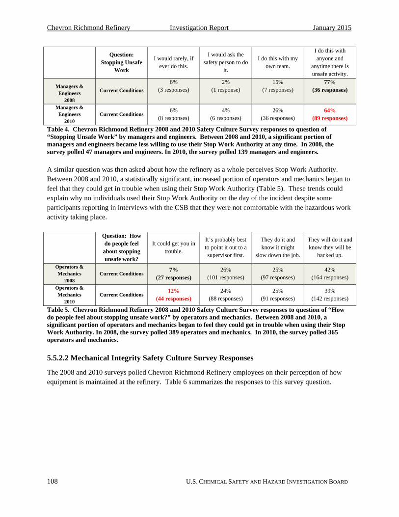
Chevron Richmond Refinery Investigation Report January 2015
108 U.S. CHEMICAL SAFETY AND HAZARD INVESTIGATION BOARD
Question:
Stopping Unsafe Work
I would rarely, if ever do this.
I would ask the safety person to do
it.
I do this with my own team.
I do this with anyone and
anytime there is unsafe activity.
Managers & Engineers
2008
Current Conditions
6% (3 responses)
2% (1 response)
15% (7 responses)
77% (36 responses)
Managers & Engineers
2010 Current Conditions
6% (8 responses)
4% (6 responses)
26% (36 responses)
64% (89 responses)
Table 4. Chevron Richmond Refinery 2008 and 2010 Safety Culture Survey responses to question of “Stopping Unsafe Work” by managers and engineers. Between 2008 and 2010, a significant portion of managers and engineers became less willing to use their Stop Work Authority at any time. In 2008, the survey polled 47 managers and engineers. In 2010, the survey polled 139 managers and engineers.
A similar question was then asked about how the refinery as a whole perceives Stop Work Authority. Between 2008 and 2010, a statistically significant, increased portion of operators and mechanics began to feel that they could get in trouble when using their Stop Work Authority (Table 5). These trends could explain why no individuals used their Stop Work Authority on the day of the incident despite some participants reporting in interviews with the CSB that they were not comfortable with the hazardous work activity taking place.
Question: How do people feel
about stopping unsafe work?
It could get you in trouble.
It’s probably best to point it out to a supervisor first.
They do it and know it might
slow down the job.
They will do it and know they will be
backed up.
Operators & Mechanics
2008 Current Conditions
7% (27 responses)
26% (101 responses)
25% (97 responses)
42% (164 responses)
Operators & Mechanics
2010 Current Conditions
12% (44 responses)
24% (88 responses)
25% (91 responses)
39% (142 responses)
Table 5. Chevron Richmond Refinery 2008 and 2010 Safety Culture Survey responses to question of “How do people feel about stopping unsafe work?” by operators and mechanics. Between 2008 and 2010, a significant portion of operators and mechanics began to feel they could get in trouble when using their Stop Work Authority. In 2008, the survey polled 389 operators and mechanics. In 2010, the survey polled 365 operators and mechanics.
5.5.2.2 Mechanical Integrity Safety Culture Survey Responses
The 2008 and 2010 surveys polled Chevron Richmond Refinery employees on their perception of how equipment is maintained at the refinery. Table 6 summarizes the responses to this survey question.

Chevron Richmond Refinery Investigation Report January 2015
109 U.S. CHEMICAL SAFETY AND HAZARD INVESTIGATION BOARD
Question: How do we take care of equipment?
Equipment is not cared for, and we
often have breakdowns and
near misses.
We have procedures for updating and
maintaining our equipment but
they are not always followed.
We use procedures for updating and maintaining our equipment but
they are not always up to date.
We work hard to think about what
can go wrong, and fix the equipment before it causes
harm.
All Employees 2008
Current Conditions 8% (53 responses)
26% (172 responses)
35% (231 responses)
31% (205 responses)
All Employees 2008
Hoped-for Conditions
1% (7 responses)
5% (33 responses)
8% (53 responses)
86% (568 responses)
All Employees 2010
Current Conditions 12% (112 responses)
27% (253 responses)
30% (281 responses)
31% (290 responses)
All Employees 2010
Hoped-for Conditions
2% (19 responses)
4% (37 responses)
9% (84 responses)
85% (796 responses)
Table 6. Chevron Richmond Refinery 2008 and 2010 Safety Culture Survey responses to the question: “How do we take care of equipment?”
Both surveys revealed that most employees felt procedures to maintain equipment were not always up to date, were not always followed, or that equipment was not properly maintained despite most individuals’ desire that the refinery fix equipment before it causes harm. Between the 2008 and 2010 surveys, a statistically significant portion of operators and mechanics began to feel that equipment was not cared for at the refinery. In addition, a statistically significant number of managers and engineers expressed that procedures for updating and maintaining equipment were not always followed. These results indicate that Chevron Richmond Refinery employees identified increased weakness in their mechanical integrity programs, which could result in equipment failures, such as the incident on August 6, 2012.
5.5.2.3 Process Safety Analysis Safety Culture Survey Responses
The 2008 and 2010 surveys tasked Chevron Richmond Refinery employees to provide feedback on how process safety failures are investigated at the refinery. The survey results are shown in Table 7.
Question:
Process Safety Issues Are…
…usually not investigated.
…investigated but not always resolved.
…investigated and resolved if it’s in
the budget.
…routinely investigated,
resolved and the lessons learned are shared with others.
All Employees 2008
Current Conditions 2% (13 responses)
24% (159 responses)
21% (139 responses)
53% (350 responses)
All Employees 2008
Hoped-for Conditions
1% (6 responses)
1% (7 responses)
3% (20 responses)
95% (628 responses)
All Employees 2010
Current Conditions 3% (28 responses)
26% (243 responses)
17% (159 responses)
54% (506 responses)
All Employees 2010
Hoped-for Conditions
2% (19 responses)
1% (9 responses)
4% (37 responses)
93% (871 responses)
Table 7. Chevron Richmond Refinery 2008 and 2010 Safety Culture Survey responses to the question “Process Safety Issues Are…” Responses indicate employees desire process safety issues are investigated more thoroughly.

Chevron Richmond Refinery Investigation Report January 2015
110 U.S. CHEMICAL SAFETY AND HAZARD INVESTIGATION BOARD
The survey responses show a discrepancy between the “Current Conditions” and “Hoped-for Conditions.” While nearly all of the employees polled desired that process safety issues were “routinely investigated, resolved and the lessons learned [were] shared with others”, only about half of the employees reported that they believed the refinery achieved that goal. The safety culture survey analysis of this difference concluded, “There continues to be a very strong desire to investigate more thoroughly to ensure there is adequate learning.”
5.5.2.4 Regulator Overview of Safety Culture Survey Action Items
Contra Costa County issues regulations to covered facilities within the county through its Industrial Safety Ordinance (ISO).204 Although the City of Richmond is located in Contra Costa County, the county does not have jurisdiction over industrial facilities located within city limits. Thus, the ISO is not enforceable within the City of Richmond. On December 18, 2001, the City of Richmond adopted its own industrial safety ordinance (RISO), based on the ISO, to extend jurisdiction of a similar sort over facilities located in the city. The RISO covers two facilities—one of which is the Chevron Richmond Refinery. Pursuant to an agreement between the two parties, Contra Costa County inspects these two facilities and implements the RISO for the City of Richmond. Both the Contra Costa County ISO and the City of Richmond RISO require covered facilities to perform safety culture assessments at least once every five years.205 In addition, Contra Costa County published an “Industrial Safety Ordinance Guidance Document” that establishes additional requirements covered facilities must perform. Section F: Safety Culture Assessments requires facilities to maintain the following records, which can be audited by the regulator:
a. Safety Culture Assessment reports;
b. Stated facility goals and objectives regarding safety culture and related topics;
c. Documentation of the appropriateness of the participation level targeted and achieved;
d. Assessment methodologies used for each work group and criteria for successful implementation;
e. Criteria used for rejection of any results or findings;
f. Criteria used for determining if no action(s) will be taken on assessment results or recommendations;
g. Summary of the assessment components with key findings;
h. Improvement plan with clear list of action items and identifiable milestones;
i. Rationale for prioritizing action items and justification for the action items;
204 For more information on the Contra Costa County Industrial Safety Ordinance, and the City of Richmond
Industrial Safety Ordinance, see the CSB’s draft Regulatory Report, http://www.csb.gov/chevron-refinery-fire/ (accessed September 9, 2014).
205 The Contra Costa County ISO has required covered facilities to perform Safety Culture Assessments at least every five years since 2006, but Richmond did not adopt these requirements until February 2013. See http://www.ci.richmond.ca.us/documentcenter/view/26375, page 22 (accessed July 11, 2014) and http://www.ci.richmond.ca.us/ArchiveCenter/ViewFile/Item/4988 (accessed December 21, 2014).

Chevron Richmond Refinery Investigation Report January 2015
111 U.S. CHEMICAL SAFETY AND HAZARD INVESTIGATION BOARD
j. Documentation of communications to workforce; and
k. Qualitative and quantitative comparisons in subsequent assessments of whether improvement plans affected observable safety behavior, or culture.206
As items (h) and (k) show, Contra Costa County and the City of Richmond require facilities to develop an improvement plan based on the safety culture assessment findings. The facilities must also monitor whether the improvement plan results in observable changes to safety behavior and culture. These items set a requirement for facilities to strive for continuous improvement in process safety culture. However, no means are in place for the regulator to ensure that the action items are of sufficient quality to promote cultural change. As is currently written in the Contra Costa County guidance document, the regulator only requires facilities to develop action items following the conduct of safety culture assessments. The quality of these action items can be subpar, lacking in capability to significantly change culture, yet the regulator must still approve them in its document-verification audits.
In the years leading to the August 6, 2012 incident, the Chevron Richmond Refinery identified weaknesses in its Stop Work Authority program due to employees’ hesitation to use their Stop Work Authority when they witnessed an unsafe act occurring. The refinery also identified a deteriorating employee perception of the mechanical integrity programs used at the refinery. However, the Chevron Richmond Refinery was not required to take quality, constructive steps to improve these areas.207 Had steps been taken prior to the incident to find ways to encourage employees to use their Stop Work Authority or to determine why the refinery’s mechanical integrity programs were seen as deficient, the August 6, 2012, pipe rupture might have been prevented.
Contra Costa County and the City of Richmond should enhance the ISO and RISO, respectively, to require the development of an oversight committee to monitor the development and implementation of action items created as a result of safety culture assessment findings. This committee should also assess whether the action items that result from the safety culture assessments have the potential to effectively lead to improved process safety culture in the facility. This oversight committee should be comprised of regulator representatives, company representatives, and members of the workforce and their representatives. Many citizens of Contra Costa County and Richmond, California, are concerned about the environmental impacts of industrial process incidents on their community, so they passionately advocate for improved industrial process safety at the petrochemical facilities in the county. For this reason, it is important that Contra Costa County community members play an active role in overseeing and providing input into process safety culture improvement efforts at petrochemical facilities in Contra Costa and Richmond. Ideally, one to two community members—who are selected by their peers based upon their ability to effectively (1) communicate the concerns of community members and (2) provide valuable input into the process safety culture improvement plans—will also be member(s) of this oversight committee.
206 http://cchealth.org/hazmat/pdf/iso/section_f.pdf (accessed July 14, 2014). 207 Under the RISO, Chevron was not required to conduct safety culture assessments until February 2013.

Chevron Richmond Refinery Investigation Report January 2015
112 U.S. CHEMICAL SAFETY AND HAZARD INVESTIGATION BOARD
6.0 Recommendations
Under the authority of 42 U.S.C. §7412(r)(6)(C)(i) and (ii), and in the interest of promoting safer operations at petroleum refineries and protecting workers and communities from future accidents nationwide, the CSB makes the following safety recommendations:
6.1 American Petroleum Institute
2012-03-I-CA-R26
Revise API RP 939-C: Guidelines for Avoiding Sulfidation (Sulfidic) Corrosion Failures in Oil Refineries to establish minimum requirements for preventing catastrophic rupture of low-silicon carbon steel piping. At a minimum:
a. Require users to identify carbon steel piping circuits susceptible to sulfidation corrosion that may contain low-silicon components. These circuits have the potential to contain carbon steel components that were not manufactured to the American Society for Testing and Materials (ASTM) A106 specification and may contain less than 0.10 weight percent silicon content.
b. For piping circuits identified to meet the specifications detailed in 2012-03-I-CA-R26(a), require users to either (1) enact a program to inspect every component within the piping circuit once, known as 100 percent component inspection (per the requirements established pursuant to recommendation 2012-03-I-CA-28(c)), or (2) replace the identified at-risk carbon steel piping with a steel alloy that is more resistant to sulfidation corrosion.
c. If low-silicon components or components with accelerated corrosion are identified in a carbon steel piping circuit meeting the specifications detailed in 2012-03-I-CA-R26(a), require designation of these components as permanent Condition Monitoring Locations (CMLs) until the piping components are replaced.
2012-03-I-CA-R27
Revise API RP 571: Damage Mechanisms Affecting Fixed Equipment in the Refining Industry to:
a. Describe the potential for increased rates of sulfidation corrosion occurring in low-silicon carbon steel in Section 4.4.2.3 Critical Factors;
b. Specify that sulfidation corrosion rates in carbon steel piping can be significantly faster in a few, individual piping components in section 4.4.2.5 Appearance or Morphology of Damage; and
c. Refer the reader to the 100 percent component inspection or pipe replacement requirements detailed in API RP 939-C: Guidelines for Avoiding Sulfidation (Sulfidic) Corrosion Failures in Oil Refineries (pursuant to recommendation 2012-03-I-CA-26) and API 570: Piping Inspection Code: In-service Inspection, Rating, Repair, and Alteration of Piping Systems (pursuant to

Chevron Richmond Refinery Investigation Report January 2015
113 U.S. CHEMICAL SAFETY AND HAZARD INVESTIGATION BOARD
2012-03-I-CA-28(c)) for carbon steel piping circuits susceptible to sulfidation corrosion that may contain low-silicon components.
2012-03-I-CA-R28
Revise API 570: Piping Inspection Code: In-service Inspection, Rating, Repair, and Alteration of Piping Systems to:
a. Use terminology consistent with API RP 939-C: Guidelines for Avoiding Sulfidation (Sulfidic) Corrosion Failures in Oil Refineries and other API standards and recommended practices discussed in this report. Replace the terminology “high-temperature sulfur corrosion” with “sulfidation corrosion”;
b. Specify that sulfidation corrosion rates in carbon steel piping can be significantly faster in some individual piping components than in others;
c. Establish a new section that details inspection requirements to identify low-silicon piping components in carbon steel circuits susceptible to sulfidation corrosion. This section shall require users to identify carbon steel piping circuits at risk to contain low-silicon components by following the requirements detailed in API RP 939-C: Guidelines for Avoiding Sulfidation (Sulfidic) Corrosion Failures in Oil Refineries (pursuant to 2012-03-I-CA-26(a)) and API RP 578: Material Verification Program for New and Existing Alloy Piping Systems (pursuant to 2012-03-I-CA-29). At a minimum, require users to either:
i. Inspect every component within all carbon steel piping circuits susceptible to sulfidation corrosion that may contain low-silicon components once. The purpose of this practice is to identify any low-silicon components that are corroding at accelerated rates. Inspection may be performed through ultrasonic thickness measurements to establish corrosion rates for each component, destructive laboratory analysis, or other methods. Following the inspection, require users to follow the low-silicon corrosion rate monitoring requirements established in 2012-03-I-CA-R26(c); or
ii. Replace the identified at-risk carbon steel piping with a steel alloy that is more resistant to sulfidation corrosion.
d. Incorporate as a “normative reference” API RP 939-C: Guidelines for Avoiding Sulfidation (Sulfidic) Corrosion Failures in Oil Refineries; and
e. Require users to follow the minimum leak response guidance established in API RP 2001: Fire Protection in Refineries, developed in response to recommendation 2012-03-I-CA-R31.

Chevron Richmond Refinery Investigation Report January 2015
114 U.S. CHEMICAL SAFETY AND HAZARD INVESTIGATION BOARD
2012-03-I-CA-R29
Revise API RP 578: Material Verification Program for New and Existing Alloy Piping Systems, to require users to establish and implement a program to identify carbon steel piping circuits that are susceptible to sulfidation corrosion and may contain low-silicon components. These circuits have the potential to contain carbon steel components that were not manufactured to the American Society for Testing and Materials (ASTM) A106 specification and may contain less than 0.10 weight percent silicon content. Refer the reader to the 100 percent component inspection or pipe replacement requirements detailed in API RP 939-C: Guidelines for Avoiding Sulfidation (Sulfidic) Corrosion Failures in Oil Refineries (pursuant to recommendation 2012-03-I-CA-26(b)) and API 570: Piping Inspection Code: In-service Inspection, Rating, Repair, and Alteration of Piping Systems (pursuant to 2012-03-I-CA-28(c)) for carbon steel piping circuits susceptible to sulfidation corrosion that may contain low-silicon components.
2012-03-I-CA-R30
Revise API RP 574: Inspection Practices for Piping System Components (3rd edition) to:
a. Incorporate as a normative reference API RP 939-C: Guidelines for Avoiding Sulfidation (Sulfidic) Corrosion Failures in Oil Refineries;
b. Reference API RP 939-C: Guidelines for Avoiding Sulfidation (Sulfidic) Corrosion Failures in Oil Refineries when discussing that nonsilicon-killed carbon steel is susceptible to sulfidation corrosion; and
c. In Section 9.3 Investigation of Leaks, require users to follow the leak response protocol requirements established in API RP 2001: Fire Protection in Refineries (pursuant to 2012-03-I-CA-R31).
2012-03-I-CA-R31
Revise API RP 2001: Fire Protection in Refineries to require users to develop a process fluid leak response protocol specific to their own facility that must be followed when a process fluid leak is discovered. Recommend users to incorporate the following actions into their leak response protocol:
a. Establish an Incident Command structure upon identification of a process fluid leak;
b. Conduct a pre-response meeting with personnel with specific technical expertise (e.g., inspectors, operators, metallurgists, engineers, and management) and the Incident Commander to determine pressure, temperature, remaining inventory of process fluids, potential damage mechanisms that caused the leak, and worst-case leak scenario;

Chevron Richmond Refinery Investigation Report January 2015
115 U.S. CHEMICAL SAFETY AND HAZARD INVESTIGATION BOARD
c. Establish a hot zone that identifies the area of risk of exposure or injuries due to flame contact, radiant heat, or contact to hazardous materials, taking into consideration the worst-case leak scenario;
d. Limit site access around leak location to essential personnel only;
e. Isolate the leaking piping or vessel, or if isolation is not possible, shutdown of the unit when the leaking process fluid poses immediate danger to safety, health, or the environment—such as piping fluid that is toxic or near the autoignition temperature.
6.2 American Society of Mechanical Engineers
2012-03-I-CA-R32
Revise ASME PCC-2-2011: Repair of Pressure Equipment and Piping to require users to follow the minimum process fluid leak response requirements established in API RP 2001: Fire Protection in Refineries, developed in response to recommendation 2012-03-I-CA-R31, before conducting process fluid leak repair.
6.3 Chevron USA
2012-03-I-CA-R33
Develop a method to assign accountability at Chevron to determine whether any new Energy Technology Company (ETC) recommended program or industry best practice, such as API guidance must be followed to ensure process safety or employee personal safety. This method shall include monitoring of these practices and guidance at a refining system level and at the refinery level. Develop a tracking system to monitor the progress of implementing these selected practices and guidance to completion.
2012-03-I-CA-R34
Develop an auditable process to be available for all recommended turnaround work items necessary to address mechanical integrity deficiencies or inspection recommendations that are denied or deferred. This process shall provide the submitter of the denied or deferred recommendation with the option to seek further review by his or her manager, who can further elevate and discuss the recommendation with higher level management, such as the Area Business Unit Manager. Maintain an auditable log of each of these potential turnaround work items, including the ultimate determination of approval, deferral, or rejection, justification determination, and the person or team responsible for that decision.
2012-03-I-CA-R35
Develop an approval process that includes a technical review that must be implemented prior to resetting the minimum alert thickness to a lower value in the inspection database.
Chevron Richmond Refinery Investigation Report January 2015
116 U.S. CHEMICAL SAFETY AND HAZARD INVESTIGATION BOARD
6.4 Board of Supervisors, Contra Costa County, California
2012-03-I-CA-R36
Revise the Industrial Safety Ordinance (ISO) regulations for petroleum refineries to require a process safety culture continuous improvement program including a written procedure for periodic process safety culture surveys across the work force. Require an oversight committee comprised of the regulator, the company, the company’s workforce and their representatives, and community representatives. This oversight committee shall:
a. Select an expert third party that will administer a periodic process safety culture survey;
b. Review and comment on the third party expert report developed from the survey;
c. Oversee the development and effective implementation of action items to effectively address identified process safety culture issues; and
d. Develop process safety culture indicators to measure major accident prevention performance.
The periodic process safety culture report shall be made available to the plant workforce.
6.5 Mayor and City Council, City of Richmond, California
2012-03-I-CA-R37
Revise the Richmond Industrial Safety Ordinance (RISO) regulations for petroleum refineries to require a process safety culture continuous improvement program including a written procedure for periodic process safety culture surveys across the work force. Require an oversight committee comprised of the regulator, the company, the company’s workforce and their representatives, and community representatives. This oversight committee shall:
a. Select an expert third party that will administer a periodic process safety culture survey;
b. Review and comment on the third party expert report developed from the survey;
c. Oversee the development and effective implementation of action items to effectively address identified process safety culture issues; and
d. Develop process safety culture indicators to measure major accident prevention performance.
The periodic process safety culture report shall be made available to the plant workforce.

Appendix A
117 U.S. CHEMICAL SAFETY AND HAZARD INVESTIGATION BOARD
Appendix A—Chevron Leak Response Protocol Developed Post-incident

Appendix A
118 U.S. CHEMICAL SAFETY AND HAZARD INVESTIGATION BOARD

Appendix A
119 U.S. CHEMICAL SAFETY AND HAZARD INVESTIGATION BOARD

Appendix B
120 U.S. CHEMICAL SAFETY AND HAZARD INVESTIGATION BOARD
Appendix B—Contra Costa County Community Warning System
Following the incident, Contra Costa County’s Community Warning System was used to notify the surrounding community of the hazardous material incident and order a shelter-in-place. But for many people, the warning came hours after the Chevron fire began. The Community Warning System uses sirens, the news media, and phone calls to residents to initiate the shelter-in-place. Contra Costa County issued the shelter-in-place advisory on August 6, 2012, at 6:38 p.m. for the cities of Richmond, San Pablo, and North Richmond, and lifted the shelter-in-place later that evening at 11:12 p.m. However, some phone calls notifying residents of the shelter-in-place advisory did not occur until over four hours after the release. This delay could have resulted in nearby residents unnecessarily and unknowingly being exposed to materials released to the atmosphere during the Chevron process leak and fire.
Since the incident, Contra Costa County has made efforts to improve the Community Warning System. It has contracted with a new vendor that will automatically call Contra Costa County residents in an emergency.208
208 See http://concord-ca.patch.com/groups/politics-and-elections/p/contra-costa-county-testing-new-community-
alert-system and http://www.contracosta.ca.gov/documentcenter/view/8161.

Appendix C
121 U.S. CHEMICAL SAFETY AND HAZARD INVESTIGATION BOARD
Appendix C—Usage of Clamps at Chevron Richmond Refinery
The CSB committed to analyzing Chevron’s culture of using clamps to temporarily stop a process fluid leak in “Additional Issues Currently Under Investigation” in its Interim Investigation Report on the August 6, 2012, Chevron Richmond Refinery incident. Following the August 6, 2012 incident, Cal/OSHA issued a citation to Chevron for nine temporary nonwelding repairs that had not been removed at the most recent turnaround.209 The CSB analyzed this citation and all available evidence on clamp usage at the Chevron Richmond Refinery. The CSB could not take a conclusive stance on whether the refinery over-relied on temporary leak repair clamps in its mechanical integrity program based upon available evidence. In addition, the CSB did not find any direct or relevant linkage between the specific clamps for which the citations were issued and the incident. As a result, this report does not analyze the use of leak repair clamps at the Chevron Richmond Refinery.
209 Division of Occupational Safety and Health, Cal/OSHA Process Safety Management District Office. Citation
and Notification of Penalty. Inspection Number 314332370; Citations Issued to Chevron U.S.A. Inc.; Issuance Date 01/30/2013. Citation 8 Item 1. See http://www.dir.ca.gov/dosh/citations/Chevron_314332370_cites_issued_1-30-13.pdf#zoom=100 (accessed November 5, 2014).

Chevron Richmond Refinery Investigation Report January 2015
122 U.S. CHEMICAL SAFETY AND HAZARD INVESTIGATION BOARD