chp integrated with burners for packaged boilers/67531/metadc867430/m2/1/high_res... ·...
TRANSCRIPT
DE-EE0004354,
CHP INTEGRATED WITH BURNERS FOR PACKAGED BOILERS
U.S. DOE Grant: EE-0004354
FINAL REPORT
July 10, 2013
Prepared for
U.S. DOE/NETL Pittsburgh Campus
626 Cochrans Mill Road PO Box 10940
Pittsburgh, PA 15236-0940
Prepared by
Carlo Castaldini
Principal Investigator CMCE, Inc.
2900 Gordon Avenue, Suite 100 Santa Clara, CA 95051
and
Eric Darby Program Manager
Altex Technologies Corporation 244 Sobrante Way
Sunnyvale, CA 94086
DOE Project Manager: Charles T. Alsup ([email protected] DOE HQ Contact: Bob Gemmer ([email protected]) DOE Administrator: Thomas Gruber ([email protected])
Page 1 of 63

DE-EE0004354,
DISCLAMER
This report was prepared as an account of work sponsored by an agency of the United States Government. Neither the United States Government nor any agency thereof, nor any of their employees, makes any warranty, express or implied, or assumes any legal liability or responsibility for the accuracy, completeness, or usefulness of any information, apparatus, product, or process disclosed, or represents that its use would not infringe privately owned rights. Reference herein to any specific commercial product, process, or service by trade name, trademark, manufacturer, or otherwise does not necessarily constitute or imply its endorsement, recommendation, or favoring by the United States Government or any agency thereof. The views and opinions of authors expressed herein do not necessarily state or reflect those of the United States Government or any agency thereof.
Page 2 of 63

DE-EE0004354,
ABSTRACT................................................................................................................................ 7 EXECUTIVE SUMMARY ........................................................................................................ 8
1.0 SUMMARY OF ACCOMPLISHMENTS ......................................................................... 9 2.0 PROJECT ACTIVITIES................................................................................................... 11 2.0 PROJECT ACTIVITIES................................................................................................... 11
2.1 Equipment Purchase...................................................................................................... 11 2.2 Combustor Development .............................................................................................. 16 2.3 Burner Head Development ........................................................................................... 21 2.4 Integrated Controls Development ................................................................................. 26 2.5 System Assembly.......................................................................................................... 29 2.6 Laboratory Testing........................................................................................................ 34 2.7 Field Installation ........................................................................................................... 40 2.8 Field Performance Tests ............................................................................................... 50
3.0 PRODUCTS DEVELOPED ............................................................................................. 61 3.1 Publications................................................................................................................... 61 3.2 Web Site........................................................................................................................ 61 3.3 Networks and Collaborations........................................................................................ 61 3.4 Technologies and Techniques....................................................................................... 61 3.5 Inventions and Patents .................................................................................................. 61 3.5 Other Products .............................................................................................................. 62
4.0 CONCLUSIONS............................................................................................................... 63
Page 3 of 63

DE-EE0004354,
LIST OF TABLES
Table 1: Sample test data on Standard CHP operation (1/2) ........................................................ 55 Table 2: Sample test data of standard CHP operation (2/2).......................................................... 56 Table 3: Summary CHP emissions - total fuel consumption 2.4 to 7.3 MMBtu/hr ..................... 57
Page 4 of 63

DE-EE0004354,
LIST OF FIGURES
Figure 1: Turbec T-100 microturbine ........................................................................................... 12 Figure 2: EEI 400 VAC, 50 Hz Power Electronics ...................................................................... 12 Figure 3: Various cables and connectors ...................................................................................... 13 Figure 4: Cooling oil tank, part of the balance of plant (BOP)..................................................... 13 Figure 5: Emerson scroll compressor ........................................................................................... 14 Figure 6: CompAir gas compressor .............................................................................................. 14 Figure 7: Fireye Nexus 6000 touch screen interface .................................................................... 15 Figure 8: NOx as a function of flame temperature ....................................................................... 16 Figure 9: NOx emissions versus primary zone stoichiometry - air dilution tests......................... 17 Figure 10: Combustor design........................................................................................................ 18 Figure 11: Fabricated combustor .................................................................................................. 19 Figure 12: Main combustion zone with thermal paint .................................................................. 19 Figure 13: Detail of fuel injection spokes for pilot (horizontal) and secondary zone (vertical)... 20 Figure 14: Burner design - Rear view........................................................................................... 22 Figure 15: Mechanical design - view of primary inlet swirler...................................................... 23 Figure 16: Fabricated burner - view of exit plane......................................................................... 23 Figure 17: Computation Fluid Dynamics (CFD) modeling of educted air................................... 24 Figure 18: Burner head CFD results - Eductor at left, burner head at right ................................. 25 Figure 19: Fabricated microturbine-burner interface.................................................................... 25 Figure 20: Fireye Nexus System installed in the laboratory for burner simulation tests.............. 26 Figure 21: Fuel control schedule model results ............................................................................ 27 Figure 22: Completed assembly drawing of Power Burner.......................................................... 29 Figure 23: Simple cycle modification and assembly .................................................................... 30 Figure 24: Photo of the simple cycle microturbine placed in the center section of cabinet ......... 31 Figure 25: Microturbine, interface and air supply assembled....................................................... 31 Figure 26: Assembly in microturbine cabinet in progress showing support structure ................. 32 Figure 27: Assembly of the cabinet with detail of air intake section............................................ 32 Figure 28: Internal detail of the interface section ......................................................................... 33 Figure 29: Combustor atmospheric test stand............................................................................... 34 Figure 30: Combustors proven to meet CARB 2007 emission limits .......................................... 35 Figure 31: Drawing of the laboratory set up................................................................................. 35 Figure 32: Superior firetube installed in place in Altex laboratory .............................................. 36 Figure 33: Power Burner being fitted to the test boiler ................................................................ 36 Figure 34: Flow measurement tests for boiler burner................................................................... 37 Figure 35: NOx and CO emissions during burner only laboratory tests....................................... 38 Figure 36: Westin Hotel Costa Mesa, CA .................................................................................... 40 Figure 37: Burner head removed from laboratory and readied for shipping ................................ 41 Figure 38: Microturbine being readies for shipment to site.......................................................... 42 Figure 39: Installation layout ........................................................................................................ 42 Figure 40: Power Burner main components placed on platform and attached to boiler............... 43 Figure 41: Progress in connecting electrical wiring and controls................................................. 43 Figure 42: View of installed system from BOP cabinet side........................................................ 44 Figure 43: Overall view of fully installed system......................................................................... 44 Figure 44: Placement of CompAir fuel gas compressor............................................................... 45 Figure 45: PE and transformer located outside of boiler room..................................................... 46
Page 5 of 63

DE-EE0004354,
Figure 46: Southern California Edison electrical control panel used for interconnection............ 46 Figure 47: Installation contractor inspecting new Bechwith relay ............................................... 48 Figure 48: Replaced fuel control valves due to weld contamination from natural gas piping ..... 49 Figure 49: Typical firing rate variation at Westin Hotel............................................................... 51 Figure 50: Fireye BMS display showing standard CHP operating mode..................................... 51 Figure 51: Close-up of boiler display panel showing steam pressure and flame scanning operation ....................................................................................................................................... 52 Figure 52: Laptop computer data acquisition system (DAS)........................................................ 53 Figure 53: PE display panel showing 97.1 kW generation........................................................... 53 Figure 54: Excess O2 levels during standard CHP mode.............................................................. 57 Figure 55: Comparison of NOx emissions before and after retrofit ............................................. 58 Figure 56: Comparison of CO emissions before and after retrofit ............................................... 59 Figure 57: Calculated NOx contribution of burner head in standard CHP mode......................... 59 Figure 59: Pre- and post-retrofit boiler efficiency changes .......................................................... 60
Page 6 of 63

DE-EE0004354,
ABSTRACT The objective of this project was to engineer, design, fabricate, and field demonstrate a Boiler Burner Energy System Technology (BBEST) that integrates a low-cost, clean burning, gas-fired simple-cycle (unrecuperated) 100 kWe (net) microturbine (SCMT) with a new ultra low-NOx gas-fired burner (ULNB) into one compact Combined Heat and Power (CHP) product that can be retrofit on new and existing industrial and commercial boilers in place of conventional burners. The Scope of Work for this project was segmented into two principal phases: (Phase I) Hardware development, assembly and pre-test and (Phase II) Field installation and demonstration testing. Phase I was divided into five technical tasks (Task 2 to 6). These tasks covered the engineering, design, fabrication, testing and optimization of each key component of the CHP system principally, ULNB, SCMT, assembly BBEST CHP package, and integrated controls. Phase I work culminated with the laboratory testing of the completed BBEST assembly prior to shipment for field installation and demonstration. Phase II consisted of two remaining technical tasks (Task 7 and 8), which focused on the installation, startup, and field verification tests at a pre-selected industrial plant to document performance and attainment of all project objectives. Technical direction and administration was under the management of CMCE, Inc. Altex Technologies Corporation lead the design, assembly and testing of the system. Field demonstration was supported by Leva Energy, the commercialization firm founded by executives at CMCE and Altex. Leva Energy has applied for patent protection on the BBEST process under the trade name of Power Burner and holds the license for the burner currently used in the product. The commercial term Power Burner is used throughout this report to refer to the BBEST technology proposed for this project. The project was co-funded by the California Energy Commission and the Southern California Gas Company (SCG), a division of Sempra Energy. These match funds were provided via concurrent contracts and investments available via CMCE, Altex, and Leva Energy The project attained all its objectives and is considered a success. CMCE secured the support of GI&E from Italy to supply 100 kW Turbec T-100 microturbines for the project. One was purchased by the project’s subcontractor, Altex, and a second spare was purchased by CMCE under this project. The microturbines were then modified to convert from their original recuperated design to a simple cycle configuration. Replacement low-NOx silo combustors were designed and bench tested in order to achieve compliance with the California Air Resources Board (CARB) 2007 emission limits for NOx and CO when in CHP operation. The converted microturbine was then mated with a low NOx burner provided by Altex via an integration section that allowed flow control and heat recovery to minimize combustion blower requirements; manage burner turndown; and recover waste heat. A new fully integrated control system was designed and developed that allowed one-touch system operation in all three available modes of operation: (1) CHP with both microturbine and burner firing for boiler heat input greater than 2 MMBtu/hr; (2) burner head only (BHO) when the microturbine is under service; and (3) microturbine only when boiler heat input requirements fall below 2 MMBtu/hr. This capability resulted in a burner turndown performance of nearly 10/1, a key advantage for this technology over conventional low NOx burners. Key components were then assembled into a cabinet with additional support systems for generator cooling and fuel supply. System checkout and performance tests were performed in the laboratory. The assembled system and its support equipment were then shipped and installed at a host facility where final performance tests were conducted following efforts to secure fabrication, air, and operating permits. The installed power burner is now in commercial operation and has achieved all the performance goals.
Page 7 of 63

DE-EE0004354,
EXECUTIVE SUMMARY
Small-scale CHP systems, where the high-temperature exhaust from a prime mover is
used as combustion air for steam or hot water generation, have the potential to increase the efficiency of converting natural gas to electricity from a nominal 30-45 percent to 80 percent, and as such have significant energy savings and global climate benefits for the economy and the planet. This project was designed to further the development Power Burner technology, pioneered by CMCE, of using the integration of a simple-cycle microturbine with an industrial burner as an assembled package that can be used as a replacement for conventional boiler burners resulting in energy savings and providing the boilers owners/operators for the first time with a return on their burner investment. The commercial acceptance of this new product, however, depends on solutions to key design, costs, performance and reliability challenges that have precluded widespread market acceptance of small-scale Distributed Generation (DG) CHP systems, namely the seamless integration of low-cost and reliable power generator with industrial and commercial packaged boilers in user friendly CHP systems. Large-scale (multi MW) CHP plants have advantages from economies of scale. However, the siting of these larger CHP plants is limited as they must rely on large demand of thermal energy to fully exploit the benefits of CHP. Small-scale (<250 kW) DG, however, is more readily integrated in numerous and dispersed DG applications, as the recovery of smaller waste heat is more manageable and more readily utilized by the user. What small CHP-DGs do not have in size advantage they make up for in the sheer numbers of potential sites and operational benefits. Industrial and commercial boilers are ideal thermal sinks for packaged simple cycle microturbines that can operate as high-temperature combustion air supply blowers for boiler burners, provided that they can accommodate all operating thermal cycles and emission limits characteristic of this class of industrial equipment. This project adds to the commercial feasibility of this small-scale distributed CHP approach by demonstrating the technical, economic, and environmental benefits of the integrated burner-microturbine technology. For example, the demonstration clearly shows that this method of distributed power generation represents the most fuel efficient way of self generation. When considering 130,000 boiler retrofit candidates in the U.S alone, the total energy savings would amount to 0.4 Quads/yr (0.4x10¹⁵ Btu/yr), including reduced transmission losses. Additional energy savings are associated with the process via reduced power use for the boiler, improved boiler turndown efficiency and reduced fan power consumption. Each 100 kW Power Burner installation translates to over $100,000 in annual savings based on boiler load factor of 66% and a spark spread defined by $0.16/kWh for electricity purchase (average between industrial and commercial sites) and $5/MMBtu for price of natural gas. These savings allow for a simple payback of 2.5 years, without incentives (less than 2 yrs with State and Federal incentives and credits), on the total package investment. Furthermore, it demonstrates the feasibility of the system to maintain normal boiler operation in compliance with applicable air emission permits, while reducing the carbon footprint for the operation by approximately 50 percent. The ongoing operation of the Power Burner at the host facility, located at the Westin Hotel in Costa Mesa CA, will continue to provide data on the reliability of the technology and the economic benefits of its use, so that its commercial readiness can be promoted and a new domestic energy efficiency industry can take hold.
Page 8 of 63
DE-EE0004354,
1.0 SUMMARY OF ACCOMPLISHMENTS
The project had the following list of technical, performance, and commercial objectives:
• Technical Objectives: o Procure microturbine equipment for use in the Power Burner o Convert microturbine to simple-cycle o Design, fabricate and test a new low-NOx combustor o Design, fabricate and test a microturbine-burner interface o Design, fabricate and test a new low NOx combustor to operate with microturbine
exhaust o Design, fabricate and assemble microturbine and burner components into one
assembly o Design fabricate and test integrated burner and microturbine control system for
single panel operation with especially designed software o Assemble and test the complete Power Burner system in the laboratory to
optimize design and controls and document performance o Secure a host facility for field demonstration o Obtain all applicable permits to allow installation, testing, and operation o Install and check out system in the field o Perform field testing and document performance
• Performance Objectives: o Compliance with CARB 2007 NOx, CO, and VOC emissions of ≤0.07 lb/MWh
and ≤0.10 lb/MWh and ≤0.02 lb/MWh respectively while in CHP mode o Overall CHP fuel efficiency of >80%, equivalent to boiler thermal efficiency o SCMT power conversion efficiency of 3,800 Btu/kWh o Boiler NOx and CO emissions of 9 and 50 ppm, corrected to 3%O2, in
compliance with the strictest boiler emission rules in California o An increase in boiler efficiency of greater than 2%, at part loads o Installed cost of a commercial unit at a low $700/kW o CHP product reliability on a par with conventional boiler burners
• Commercial Objectives: o Provide sufficient documentation to secure investments to commercialize the
technology The project achieved all its technical objectives. Each system component was designed, fabricated, tested and assembled in a complete unit, which was installed and tested in the laboratory and in the field. The unit is successfully in operation at the Westin hotel in Costa Mesa, CA. The technical development had to overcome some unexpected and significant setbacks, each resulting in added project cost, such as:
1. The requirement to rotate the generator to allow gravity flow of cooling oil, necessitating shipping the unit back to Europe for re-configuration
2. The failure of a generator during laboratory testing, also requiring one unit to be shipped back to Europe and replacement of the generator
3. The temporary unavailability of support from the microturbine vendor during important software modifications, resulting in delays and additional costs
4. The difficulty in securing fabrication and air permits for the field demonstration 5. The additional requirements to replace parts and install added equipment due to
inspection from Underwriters Laboratory (UL) 6. The temporary failure of the boiler necessitating boiler repairs and upgrades
Page 9 of 63

DE-EE0004354,
In spite of these temporary setbacks, the project team was able to achieve all the technical objectives for the project as indicated above. This was in part achieved by the availability of a second spare microturbine and components which allowed the project to proceed while repair work was undertaken on the damaged engine. Nonetheless, some project delays and additional costs were incurred, necessitating greater use of match funds, including funds provided from SCG for Leva Energy commercialization efforts. In general, all performance objectives were achieved with the exception of the following:
1. Power conversion efficiency (PCE), calculated by the net amount of fuel energy (fuel to the microturbine combustor minus net heat delivered to the burner, divided by the kW generated) for the technology achieved approximately 4,250 Btu/kWh resulting in a drop in PCE from about 90% to 80%, still considerably above the average of 7,500 Btu/kWh calculated by a mix of 50% older Rankine with a heat rate of 9,000 Btu/kWh and 50% modern combined cycle central plants with a heat rate of 6,500 Btu/kWh
2. Boiler NOx emissions (the sum of both microturbine-generated NOx and boiler burner-generated NOx), was in the range of about 12 to 25 ppm, corrected to 3% O2 depending on boiler heat input rate. However, these emissions were in compliance with local Air District imposed limits for this new technology
3. Installed cost of the microturbine is likely to exceed the $700/kW. This target was established based on the use of an Elliott simple cycle microturbine from a domestic supplier. Currently, the Power burner is based on a Turbec microturbine from Italy, the only microturbine available for this project.
In some cases, performance objectives were exceeded. For example, compared with
pre-retrofit boiler, boiler efficiency was improved for medium to high fire boiler operation. Boiler efficiency increased from 74.6% to 78.0%. This implies that if the boiler is kept at this high fire condition, the fuel savings due to this efficiency improvement are sufficient to offset the fuel required by the microturbine, essentially generating 100 kW of power at no cost to the user. This efficiency gain is the result of replacing current low-NOx burners that rely on high excess air operation and for burner that have a low turndown capability creating many on-off shutdown events in order to maintain steam pressures.
The project team made significant progress toward commercialization of the technology. Leva Energy (www.levaenergy.com) was founded on April 2, 2010 to commercialize the Power Burner for industrial and commercial boilers. The web site provides detail on the benefits of the technology as a replacement for conventional gas-fired boilers and in new boiler-burner sales. Leva Energy has applied for a process patent and has been active in soliciting venture capital and investments from selected industrial firms. The successful launching of Leva Energy will likely benefit from additional demonstrations and a long-term collection of performance data to document the economic benefits to the users and to the growth of the new company.
Page 10 of 63

DE-EE0004354,
2.0 PROJECT ACTIVITIES 2.0 PROJECT ACTIVITIES
This section summarizes the key project activities performed over the course of seven technical tasks. 2.1 Equipment Purchase
A key initial task was to secure the microturbine and its auxiliary equipment from an accredited vendor. The Power Burner technology is based on a simple cycle 100 kWe (net) gas-fired microturbine for its power generation. The simple-cycle design was selected to reduce the complexity and cost of conventional recuperated microturbines that are widely used in today’s distributed power generation. The higher temperature exhaust of the simple cycle microturbine is also a valuable source of energy for the URNB as it provides combustion stability in the low-NOx burner design. The simple cycle design also produces an exhaust that is lower in excess oxygen which translates to higher self-generated flue gas recirculation (FGR) rates for the added burner NOx control.
. The efforts to secure this key component for the Power Burner took place at a time of
significant transitions among microturbine vendors. In addition, because of the commitment to commercialize the technology, the project team also considered selection based on the future access to additional microturbines for follow-up commercial sales. Therefore, the project team considered the following options for microturbine supply:
• Design and develop a proprietary 100 kW microturbine under contract with one of
two engineering firms working in this space • Secure an Elliott TA-100 microturbine Elliott/Calnetix or Capstone • Secure a Turbec T-100 microturbine from GI&E/Turbec in Italy
The first approach was dismissed because the proposed cost to develop a new proprietary microturbine was considered prohibitive and not within the scope or funds available for this project. Requests for Elliott engines from Elliott, Calnetix or Capstone were not honored. Therefore, the projected focused on Turbec for its supply of microturbines. The project team visited GI&E in Italy to make the request. GI&E at the time was the manufacturer and assembler of Turbec T-100 microturbines. GI&E was also a large manufacturer of hot section parts for General Electric large Frame utility gas turbines. With support from CMCE contacts in the region, an agreement was reached for purchase of two sets of T-100 components, one set purchased with funds available under this project. The following equipment from GI&E was received in February 2011:
• Microturbine • Gas compressor • Oil and water cooling systems • Assorted cables and connectors • Power Electronics cabinet and transformer
Figure 1 shows the microturbine. Its design is based on a recuperated T-100 with volutes for compressor discharge and for combustor inlet from the recuperator. The use of a volute for channeling the compressed air to the combustor, instead of a diffuser used in the Elliot TA-100, makes the microturbine considerably larger in size and thus requires a larger assembly for the final product. Modifications to this design were necessary to convert its design
Page 11 of 63

DE-EE0004354,
to simple cycle. Figure 2 shows the power electronics (PE) cabinet. This was supplied by EEI, also in Italy. Because the PE is designed for European installations requiring 400 VAC, 50 Hz, it necessitated conversion to US standards of 480 VAC and 60 Hz. This was accomplished with the insertion of an additional transformer between the PE and the power grid. Figure 3 shows the wiring, cables and connectors, supplied by GI&E.
Figure 1: Turbec T-100 microturbine
Figure 2: EEI 400 VAC, 50 Hz Power Electronics
Figure 4 shows the cooling oil tank used for the generator bearings that is part of the
balance of plant (BOP), which includes the closed loop water cooling and for the generator and compressed air to keep oil from entering the combustion air. Finally, the GI&E equipment also came with an Emerson scroll gas compressor shown in Figure 5. This compressor was not used because it is designed for recuperated engines and is thus only capable of delivering 50% of the fuel needed in simple cycle. Figure 6 shows the vane gas compressor purchased separately from CompAir. This compressor came with remote controls that were incorporated within the integrated burner-microturbine cabinet especially designed for the Power Burner.
Page 12 of 63

DE-EE0004354,
Figure 3: Various cables and connectors
Figure 4: Cooling oil tank, part of the balance of plant (BOP)
Also included in the equipment purchased were components related to the burner
controls. The objective of the Power Burner integrated control was to integrate boiler-burner-microturbine control systems within one assembly for. The integrated Burner Management System (BMS) and microturbine Power Electronics (PE) must be tailored to monitor and control all the fuel and combustion air valves of the overall CHP assembly. The project team selected the Nexus 6000 system manufactured by Fireye Corporation. Fireye is well-known and trusted name in the industry, and this reputation could aid customer acceptance of the Power Burner The Nexus controller was also selected because it has the required input and output channels
Page 13 of 63

DE-EE0004354,
that are required for the Power Burner, and offers an easy-to-use touch screen interface, as shown in Figure 7, which, according to burner installers, is desired by many customers. Most importantly, the Nexus system offers complete customization capability through Abacus programming software. These key characteristics allow the controller to be customized as needed to communicate with the Power Electronics and operate the power burner in all required burner-only and CHP modes.
Figure 5: Emerson scroll compressor
Figure 6: CompAir gas compressor
Page 14 of 63

DE-EE0004354,
Figure 7: Fireye Nexus 6000 touch screen interface
Page 15 of 63

DE-EE0004354,
2.2 Combustor Development The Turbec combustor could not be used for this project because the NOx emissions from this combustor could not meet the CARB 2007 levels of 0.07 lb/MWh, which translate to 4.3 ppm, dry corrected to 15% O2 when operating with CHP efficiency in excess of 80 percent, as is the case with the Power Burner. Compliance with CARB 2007, though not necessarily required as no official Best Available Control Technology (BACT) was yet established for this technology at the time of the project, was nonetheless considered prudent for the field demonstration. Therefore, the project elected not to include the Turbec combustor in the equipment purchase list and to develop a new low NOx silo combustor instead, specially designed for this microturbine.
Figure 8 shows that in order to reduce Thermal NOx to these low levels, the flame temperature of a fully premixed combustor would have to be below 2250 F. This is achieved by leaning out the combustion zone with about 170-175 percent excess air (stoichiometry of 1.7-1.75), or an equivalence ratio below 0.60. Flame stability at all firing rates for the combustor becomes challenging with this amount of excess air such that fuel-air mixing and turbulence, in turn, become important design considerations in order to avoid flameouts or combustion instabilities and excessive CO emissions.
0.0
2.0
4.0
6.0
8.0
10.0
12.0
14.0
16.0
18.0
2150 2200 2250 2300 2350 2400 2450
Flame Temperature, F
NO
x, p
pm
5 milliseconds
7 milliseconds
10 milliseconds
Figure 8: NOx as a function of flame temperature
Combustor development tests were performed with a two-stage lean-lean combustor
design that incorporated a primary (pilot) zone followed by a secondary main combustion zone. The conceptual design for this combustor was based on work performed by Altex at the bench-scale level. Bench-scale tests were performed using a primary zone total fuel fraction of 0.32. As shown in Figure 9, all conditions, except one (SRRL = 0.97) have SRRL greater than one, which is fuel lean operation. As SRRL increases (i.e., excess air increases), NOx decreases. These results were obtained for secondary zone fuel lean stoichiometries, SRLL, of
Page 16 of 63

DE-EE0004354,
approximately 1.4, 1.6, and 1.8. Of course, final stoichiometries, SRT, vary with these conditions, with all final conditions being fuel lean (i.e. SRT>>1). As shown in Figure 9, NOx emissions can meet the CARB 2007 limit of 4.33ppm @ 15% O2 at higher SRRL and SRLL conditions without any further flame cooling. In addition, CO emissions were found to meet the CARB 2007 limit of 0.07 lb/MWh, for CHP with microturbine heat recovery, corresponding to 10.16 ppm @15% O2 at all conditions tested. Hydrocarbon emissions were insignificant at all conditions tested. This hydrocarbon emissions result was expected given the premixed nature of the combustor design.
Figure 9: NOx emissions versus primary zone stoichiometry - air dilution tests
Figure 10 illustrates the final design configuration for the silo combustor. The combustor
was designed with the proven two fuel injection zones concept, operating both in fuel-lean conditions required to meet 4.3 ppm NOx levels. To facilitate combustor and microturbine modifications and adaptation for the Power Burner, weekly conference calls were conducted with GI&E engineering staff. A GI&E engineer also visited the laboratory to review the re-configuration of the microturbine and answer questions on the intended microturbine operation and needed controls. Among some of the key design and operating changes were the appropriate design for the connecting flange and combustor top plate; the fuel rate conditions at the light off engine speed of 20,000 rpm; and the materials and tolerances necessary to allow for thermal expansion of the combustor liner in the microturbine housing. As shown in Figure 10, the primary or pilot zone uses four fuel injectors configured to generate a cyclonic flow to enhance the turbulence and mixing which allows for flame stability at extreme lean conditions. The hot pilot flame then supports the ignition of the main fuel, or secondary, fuel also introduced into the combustor with four equally spaced injectors aimed axially. The tip of the combustor liner is also equipped with carefully sized holes to allow for bypass air flow at all engine speeds.
Page 17 of 63

DE-EE0004354,
This bypass maintains the required air flows to each of the two combustion zones at the prescribed amounts to create the lean conditions necessary for minimal NOx formation anflame stability.
d
Figure 11 shows the fabricated combustor housing being assembled. The entire gh
ny
combustor was fabricated with Haynes 230 steel which offers the highest protection to hitemperatures. Figure 12 shows the combustor liner with thermal paint designed to highlight aexcessive temperature which could cause premature material degradation and ultimate failure. The tapered exit cone was designed to fit snuggly into the turbine inlet volute allowing for some expansion of the liner during operation. The photo also shows two of the ail inlet pipes for the secondary air inlet.
Figure 10: Combustor design
Figure 13 shows some of the detail on the fuel injectors for the pilot and main
combu ltiple
NOx
the
w
nder
stion zones. Fuel injectors for each of the air channels were fabricated with muperforated tubing to premix the fuel with the compressor discharge air before ignition. The number and size of each of the perforations was carefully calculated to deliver the correct quantity of fuel and necessary mixing to achieve the stable combustion conditions and low formation. Since each of the two zones included four separate injectors, fuel manifolds were fabricated, each with two separate inlet points to allow for equal distribution of fuel to each of four injectors. The equal distribution of fuel to each injector was paramount as any variations would affect the stoichiometries of the mixture and thus the NOx produced. The actual fuel floto each manifold was pre-programmed to meet specific conditions along the turbine speed curve provided by Turbec and delivered via two South Bend control valves, also procured uthe project.
Page 18 of 63

DE-EE0004354,
Figure 11: Fabricated combustor
Figure 12: Main combustion zone with thermal paint
Page 19 of 63

DE-EE0004354,
Figure 13: Detail of fuel injection spokes for pilot (horizontal) and secondary zone (vertical)
Page 20 of 63

DE-EE0004354,
2.3 Burner Head Development The project team selected a low NOx burner specifically tailored for operation with a microturbine hot exhaust flow. The burner has one key operational challenge – the ability to handle a fixed flow of hot (1200 F) vitiated microturbine exhaust while being able to modulate firing rate according to steam load demands on the boiler. This is definitively the case for boiler firing rate of less than about 7 MMBtu/hr for which the combustion air available in the microturbine exhaust exceeds the amount required for the burning of fuel in the boiler. Above that firing rate, additional combustion air is required, which is typically delivered with a separate combustion air blower. For boilers with a rated firing rate of 10 MMBtu/hr or lower, the burner is likely to rarely require additional combustion air beyond what is delivered by the microturbine, as most industrial and commercial boilers tend to operate well below their design capacities. Although the operation of small packaged boilers solely with microturbine-supplied combustion air represents an additional energy savings for the Power Burner, significant complexities are introduced in the ability of the burner to deliver stable combustion with part or low load turndown. In addition, the burner has to maintain NOx emission levels that are in compliance with local air permits. In California, South Coast Air Quality Management District (SCAQMD) has set the 9-ppm at 3% O2 boiler NOx standard for most areas in the State. This represents a significant challenge when one considers that the boiler stack will have the additive NOx contribution from the microturbine combustor and from the boiler burner. Therefore, the project attempted to address these burner challenges with the Altex low-NOx burner technology, licensed to Leva Energy for commercialization of the Power Burner. The selected burner design is based on the concept of a fuel-rich primary refractory-lined combustion zone followed by multiple concentric fuel-lean secondary zones. The fuel-rich zone reduces NOx formation and NOx from the microturbine due to absence of oxygen while providing a stable ignition source for fuel-lean secondaries. The fuel-rich, refractory-lined, primary stage is surrounded by six fuel-lean premixed concentric zones. Multiple fuel-lean secondary zones allow for the sequential introduction of fuel such that local stoichiometries can be controlled to suppress further NOx formation. The primary zone was also designed to have a flow spinner to impart swirling to the incoming microturbine exhaust and blower air flows in order to maximize residence time in the sub-stoichiometric zone for maximum NOx reduction capability. The burner head was also designed to accommodate four sources of oxygen: (1) turbine 1,200 F exhaust containing about 15% O2 and 15% moisture, (2) educted ambient temperature air, (3) recirculated 300-500 F flue gas (FGR) from the boiler stack containing variable 3 to 15% O2 and moisture, and (4) additional ambient air from separate blower for boiler firing rates in excess of about 6.5 MMBtu/hr. With the exception of microturbine exhaust, all other flows were designed to vary at different rates, and not necessarily in proportion to the desired firing rate, so the mechanical design had to also consider the capability of the control system to adapt to these varying flow rates and deliver the proper fuel flow to secure sub-9 ppm NOx operation. An additional complexity is introduced by changes in the exit velocities of the premixed fuel-air flows from the lean-burning secondary slots. The largest of these changes in velocities are introduced when the operation is switched between CHP and burner only. Exit velocities are important in that they support turbulence and mixing in the boiler furnace. These are conducive to stable combustion and low CO emissions. When the Power Burner operation is in CHP mode, the microturbine exhaust determines by and large the exit velocities, whereas when in burner only, low excess air operation can dramatically reduce these velocities with a resulting
Page 21 of 63

DE-EE0004354,
effect on turbulence and mixing. Therefore, the boiler burner allowed for the use of FGR to maintain needed mixing especially in Burner only operation. Figure 14 shows the burner head design viewed from the rear where turbine exhaust, added combustion air, and FGR would be introduced. Figure 15 shows inlet detail for the primary zone, including the swirler. Surrounding this primary inlet area are the fuel injection holes that accept fuel pipes for the lean burning secondary slots. The flange is then designed to bolt onto the front of the boiler according to the existing bolt pattern. Figure 16 shows the burner viewed from its exit plane. As shown, the central primary zone is refractory-lined surrounded by the six lean premixed burning zones. In order to secure a more reliable ignition of each of these lean burning zones, bleed primary zone discharge holes were inserted into the exit plane. These holes would channel the hot fuel-rich primary exhaust in the direction of the lean jets. Vitiated air is supplied to each zone via a mix of microturbine exhaust, educted air, and additional blower air as needed. One added feature of the burner is the eductor designed to recuperate the kinetic energy of the microturbine exhaust to educt additional combustion air into the burner thus reduce the dependency on an external combustion air blower. Computational modeling and experimentation was undertaken to evaluate the quantity of educted air that could be possible with the force of the microturbine exhaust. Figure 17 illustrates the results of the modeling of microturbine and educted air flows entering the plane of the burner head, downstream of the primary zone swirler section. The colors indicate the pressure levels at each section. As shown, the flow entering the burner primary zone, consisting of a mixture of microturbine exhaust and educted air, is imparted a swirling motion to generate mixing with the primary fuel and provide highest residence time before exiting and mixing with premixed lean jets from the outer secondary zones.
The educator takes advantage of the venturi effect provided the pressure downstream of the venture is not too excessive to overcome. The modeling was extended to burner head simulation as shown in Figure 18. The swirling action at the primary zone exit is evident. Results on the completed Power Burner have indicated that the educator does not provide sufficient benefits to justify the added complexity and cost of fabrication. However, for boilers designed to operate below about 8 MMBtu/hr, the use of an eductor can guarantee that the combustion air blower would not ever be in operation as long as the Power Burner is in CHP mode. However, to guarantee burner only operating mode, the Power Burner will always require a combustion air blower, an expense that cannot be avoided.
Figure 14: Burner design - Rear view
Page 22 of 63

DE-EE0004354,
Figure 15: Mechanical design - view of primary inlet swirler
Figure 16: Fabricated burner - view of exit plane
Page 23 of 63

DE-EE0004354,
Figure 17: Computation Fluid Dynamics (CFD) modeling of educted air
Page 24 of 63
DE-EE0004354,
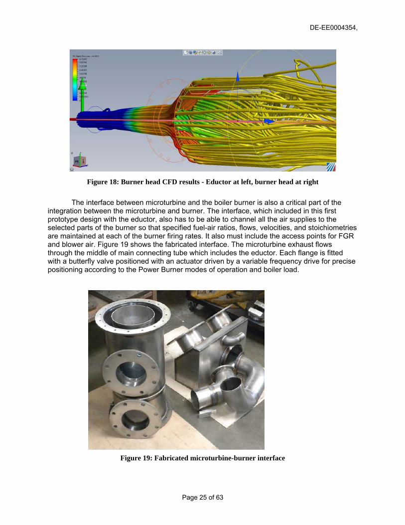
Figure 18: Burner head CFD results - Eductor at left, burner head at right
The interface between microturbine and the boiler burner is also a critical part of the
integration between the microturbine and burner. The interface, which included in this first prototype design with the eductor, also has to be able to channel all the air supplies to the selected parts of the burner so that specified fuel-air ratios, flows, velocities, and stoichiometries are maintained at each of the burner firing rates. It also must include the access points for FGR and blower air. Figure 19 shows the fabricated interface. The microturbine exhaust flows through the middle of main connecting tube which includes the eductor. Each flange is fitted with a butterfly valve positioned with an actuator driven by a variable frequency drive for precise positioning according to the Power Burner modes of operation and boiler load.
Figure 19: Fabricated microturbine-burner interface
Page 25 of 63

DE-EE0004354,
2.4 Integrated Controls Development
The key task of the controls development was to integrate the microturbine controls with a burner management system (BMS) and arrive at an easy-to-operate simple operator-machine interface that provided the flexibility to select modes of operation for the Power Burner with reliable startup, load following, and showdown events.
The project team consulted with Siemens, Fireye, and Integrated Combustion Controls (ICC) for supply of conventional BMS that could then be adapted to the more demanding control needs for the Power Burner. After significant evaluation, the team selected Fireye as the controls vendor. The regional sales manager for Fireye Corporation, offered to lend a set of controls hardware for evaluation, including a controller, touch screen and sample servo motors, which were delivered in May 2012, and were used to perform preliminary bench-scale tests, as shown in Figure 20. The Nexus 6000 Fireye controls provided all the key requirements and the added servo motor controls flexibility needed to address additional fuel and air flow controls for the Power Burner. It also include the capability for stack oxygen trim which permits feedback on the accuracy of various combustion air flows and is needed to optimize excess stack oxygen in order to maximize boiler efficiency. The following engineering analyses were used to support the overall needs for controls that would prove satisfactory for the Power Burner:
1. Preliminary control logic for integrated BMS-PE control 2. Defined requirements for BMS and PE interface 3. Initial validation of required programming of BMS to adapt to Power Burner operation
Other planned requirements for the BMS included a LCD display terminal mounted on the door of the burner control panel to provide the interface for the operator to interact with the controls. The LCD can have a touch sensitive surface that provides the operator with the ability to manipulate the control settings, if needed. In all cases, the BMS needed to provide permissive signals to the operator for selection of mode to operate and engine start up, following boiler purge. The microturbine power electronics (PE) feedback loop was required to provide annunciation to the BMS that the engine has started and has reached full generating power. This will be the signal for the BMS to start the burner ignition sequence, starting with pilot ignition, flame detection and main fuel valve open to deliver fuel to primary and secondary zones fuel control valves.
Figure 20: Fireye Nexus System installed in the laboratory for burner simulation tests
Page 26 of 63

DE-EE0004354,
Following several consultations with Fireye, the project team created an Excel-based model of the fuel control strategy which was integrated with the mechanical design requirements of the burner head. The results of this model are shown in Figure 21. This profile was programmed into Fireye’s burner management system simulator and tested across the intended range of firing rates. The Nexus was able to modulate fuel flow as programmed and no unexpected faults were produced in the servo-motor controls.
Figure 21: Fuel control schedule model results
The Burner Management System (BMS) controls the sequencing of the burner/boiler purge, light-off, and shutdown separately from the CCS. Honeywell, Siemens, Preferred Instruments, and others offer integrated controllers that incorporate both the CCS and BMS in one box. Both the CCS and BMS rely on Programmable Logic Controllers (PLCs), input/output modules, and a power supply. The input and output modules are the electrical interfaces between the PLC and the burner and boiler instrumentation for the CCS (transmitters, flow control valves, dampers, etc) and limit switches, shutoff valves, and other devices that comprise the startup and safety shutdown portion of the burner.
The following three principal modes under consideration:
1. CHP Mode – This is the main operating mode of the burner-microturbine assembly. Both burner and microturbine are operating. For a 10 MMB/hr burner capacity of the Westin operating generally at less than 7 MMBtu/hr, the eductor will be still used even though it has less functionality than for a larger boiler operating at loads between 7 and 10 MMBtu/hr. In any case, as noted before, the blower will be included in the PB design for purging the boiler, and to operate the PB with only burner head firing. The blower can also cool the microturbine enclosure during shutdown, which will minimize temperatures, in addition to the thermal insulation on the turbine housing.
2. Microturbine Only – This is the warm boiler stand-by and/or lowest thermal heat input
Page 27 of 63

DE-EE0004354,
case. This is also referred to low-CHP mode of operation because the waste heat from the microturbine can still be used by the boiler even if the boiler burner is not firing. The overall efficiency of the CHP in the low-CHP mode will be lower (60-70%) than the intended Power Burner operation (with both microturbine and boiler burner firing with efficiency of >80%) and more in line with conventional CHP systems.
3. Burner Only – This is the operating mode when the microturbine engine is not operable
for some reason. Ability to operate in this mode ensures that an installation site does not lose boiler capacity due to and routine or unexpected microturbine maintenance. While the Turbec microturbine is known to be reliable, with a 60,000 hours Mean Time Between Failures (MTBF), industry surveys have highlighted the importance of maximum boiler availability. The ability of the Power Burner to operate in this mode would reassure any potential site operators that this new technology will not have a negative effect on their boiler uptime.
Also critical to the system requirements are the additional fuel controls valves associated
with the dual-zone burner head design. The two main firing zones (one fuel rich and one fuel lean) will each have a fuel control valve, which will modulate burner output to achieve the desired boiler firing rate. The following hardware will be controlled or monitored by the PBC. Damper sizes are selected based on a single maximum boiler firing rate of 10 MMBtu/hr for the Westin boiler:
• Flame detection: UV-type, conventional functionality (similar to Honeywell RM7840 or Delphi)
• O2 trim: Conventional functionality in operation with several low NOx burners • Valve proving—Conventional functionality (similar to Honeywell RM7840 or Delphi) • Boiler Steam Pressure: Signal from Steam pressure transducer to set fuel firing rates • Burner Head Fuel #1 (Pilot): Servo-motor controlled butterfly valve • Burner Head Fuel #2 (Main): Servo-motor controlled butterfly valve • Burner Head Fuel #3 (Secondary): Servo-motor controlled butterfly valve • Additional Burner Head Fuel Control: Three solenoid-controlled fuel valves on secondary • Burner head blower: 208V 3-phase electric motor with VFD control. VFD will be
purchased separately from the PBC, but will be controlled by the PBC. • FGR Blower: 208V 3-phase electric motor with VFD control. VFD will be purchased
separately from the PBC, but will be controlled by the PBC. • FGR Damper: Servo-motor controlled butterfly valve, 6” FGR type. May switch to
solenoid/on-off control during development. • Burner Air Damper #1: Servo-motor controlled butterfly valve, 6” FGR type • Burner Air Damper #2: Servo-motor controlled butterfly valve, 8” FGR type • Purpose TBD: One additional servo-motor control, for use in development testing • Four analog inputs, for display or control • Four digital inputs, for display, boiler management, and safety/shutdown.
Page 28 of 63

DE-EE0004354,
2.5 System Assembly
The overall objective of this activity was to assemble a complete Power Burner system that could be tested in the laboratory to document and optimize operation and performance and ensure readiness for field use. Figure 22 the designed assembly of the Power Burner. Key components of the assembly include the enclosure for the microturbine and balance of plant (BOP) components; the support components for the microturbine cabinet; the system interface matching microturbine exhaust with burner inlet; and the fuel gas fuel control valve assembly and support gas train. On the right, the figure shows the interface between the microturbine and burner and the burner head. The cabinet containing the microturbine and support system is actually divided into three cabinets. The BOP cabinet shown in the foreground contains the auxiliary systems for the oil and water cooling systems and the compressed air. The larger middle cabinet contains the microturbine with its two fuel control valves. On the far left, not shown in the figure, is the cabinet that contains the combustion air filters, silencer and the combustor. Insulated bulkheads provide dividers for these three main sections of the assemble cabinet.
Figure 22: Completed assembly drawing of Power Burner The microturbine was modified to convert from a recuperated design to a simple cycle.
In order to achieve this with minimal modifications to the original equipment, it was decided to create a direct path for the compressed air to enter the combustor volute. Figure 23 shows the assembled system. A pipe was fabricated, with an expander to allow for thermal growth, to take the 500 F compressed air to a new section with concentric ducts. The outer duct was designed to receive the compressed air and directed to the combustor volute. The inner channel would
Page 29 of 63

DE-EE0004354,
then allow the microturbine exhaust to exit the turbine and move toward the boiler burner. The flange in the foreground was the used to attach the new silo combustor.
Figure 23: Simple cycle modification and assembly
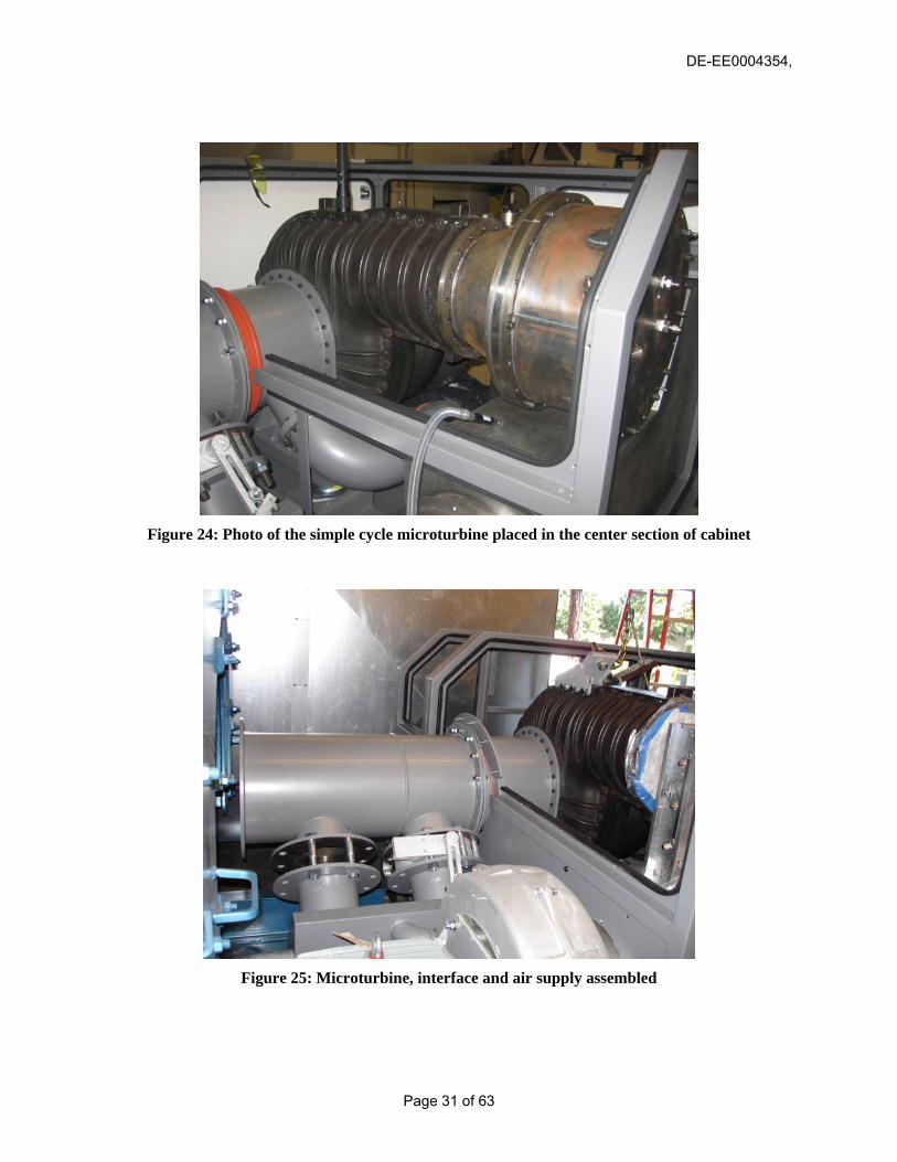
Fabrication drawings were sent to the fabricators and the system was assembled in the
combustion laboratory for testing. Figure 24 shows the microturbine being assembled in the fabricated microturbine enclosure cabinet with fasteners and support elements. Figure 25 shows the assembly of the air supply section of the microturbine cabinet. The figure shows the air inlet channel that will be filled with a noise silencer and a set of particulate filters to prevent contamination of the microturbine air compressor blades, combustor and power turbine. Figure 26 shows the progress in assembly of all components. Figure 27 shows the air-intake section being assembled.
Cabinet frame and microturbine-burner interface were professionally painted with an in
metallic gray. The figure shows that the BOP section of the cabinet was yet to be fully assembled and installed. Also, air control dampers for the fan outlet were not yet installed. Control wiring and additional sensors planned for the detailed testing in the laboratory were also not yet installed and proven. The overall form factor of the cabinet and assembly of the system considered the important floor space limitations at most industrial and commercial boiler sites. But more importantly was configured in such a way to ensure the widest possible application to commercial and industrial package boilers. Figure 28 shows the design of the internals of the interface section designed without the use of the eductor. As indicated, the interface becomes shorter and is thus more desirable in retrofits where space is of a greater consideration. In this approach, the interface has only one connection for the blower fitted with a butterfly valve and actuator for added flow control. The hot microturbine exhaust flows through the central section highlighted in yellow. The
Page 30 of 63
DE-EE0004354,
Figure 24: Photo of the simple cycle microturbine placed in the center section of cabinet
Figure 25: Microturbine, interface and air supply assembled
Page 31 of 63

DE-EE0004354,
Figure 26: Assembly in microturbine cabinet in progress showing support structure
Figure 27: Assembly of the cabinet with detail of air intake section
Page 32 of 63

DE-EE0004354,
Figure 28: Internal detail of the interface section
Page 33 of 63

DE-EE0004354,
2.6 Laboratory Testing
The laboratory testing focused on tests for critical components of the Power Burner and on tests for the entire assembly on a packaged firetube boiler in the laboratory. The microturbine combustor was first tested at atmospheric pressure on a constructed test cell shown in Figure 29. The objective was to evaluate reliable ignition and controls of pilot and main stoichiometries in order to achieve the targeted 2007 CARB limits for NOx and CO. These tests also served to finalize the various dimensions of the combustor fuel lean premised zones that are critical to ensure that peak temperatures and NOx levels in each zone are within the design specifications. Adjustments to some of the components were implemented based on the results of these tests. Figure 30 shows that, after some adjustments to fuel distribution and improved fuel injector designs, CARB 2007 were readily achieved with NOx emissions at 2.5 ppm and CO measured at 3.4 ppm, well below the CARB 2007 limits. Further validation of this performance would be necessary at actual Power Burner conditions where back pressure and turbine operation would influence the actual results.
Figure 29: Combustor atmospheric test stand
In order to provide a real test bed for the Power Burner it was necessary to test the fully assembled prototype on a real boiler where firing rates could reach actual field test conditions and the microturbine could operate at full 100 kW power output. Therefore, a new laboratory space was constructed within the Altex laboratory to install a 10 MMBtu/hr Superior Boiler Works firetube boiler with all the support equipment and instrumentation needed to simulate actual field test conditions. Figure 31 shows the laboratory setup to test the Power Burner system prior to shipment to the field. The system was supported by a complex array of heat exchangers to provide a load for the boiler generated hot water. The 100 kW load from the microturbine was dissipated using a load bank provided by CMCE. The Power Burner and boiler BMS systems for the laboratory were used for the laboratory demonstration and upon completion of the tests were shipped to the host site for installation. A spare system was provided by the DOE project and replaced the units shipped to the field. Altex upgrade the laboratory facilities to accommodate the boiler and support systems, including the delivery of fuel gas and heat exchanger assemblies. These tests
Page 34 of 63

DE-EE0004354,
also revealed that the material temperatures are well below the structural limits of the Haynes 230 material chosen for the fabrication of the combustor.
Figure 30: Combustors proven to meet CARB 2007 emission limits
Figure 31: Drawing of the laboratory set up
Page 35 of 63

DE-EE0004354,
Figures 32 and 33 show the installation progress for the laboratory test boiler and the Power Burner.
Figure 32: Superior firetube installed in place in Altex laboratory
Figure 33: Power Burner being fitted to the test boiler
Page 36 of 63

DE-EE0004354,
In addition to the silo combustor tests, the burner head was subject to several tests to validate the flow modeling results used in the design of the burner and to make appropriate adjustments as necessary to achieve combustion conditions that are needed at all boiler loads while meeting emissions. Adjustments were required to restrict combustion air flow to the primary chamber and to increase velocities in the secondaries. Figure 34 shows the flow measurements made with pitot tubes in each of the flow paths of the burner. These measurements were made with the burner out of the test boiler to make it easier to access exit planes for the measurement of air flow.
Figure 34: Flow measurement tests for boiler burner
Once the combustion air flows were established the attention turned to fuel flow
requirements for the burner at different boiler firing rates. The burner head was then inserted in the test boiler and fired with a maximum firing rate of 4.8 MMBtu/hr in burner only mode. The testing was sequential in approach where the first rich-burning zone was fired alone first in a staged air NOx control mode. These tests provided a measure of the reliability of the burner for light-off and fuel control to the primary zone. Figure 35 shows the preliminary results of burner only tests with both primary and secondary zones firing. The data shows that 9 ppm NOx, corrected to 3% O2, with low CO was achievable when some amount of FGR was used. Therefore, it was realized that FGR would most likely be needed in order to provide added measure of NOx compliance flexibility at all boiler load conditions.
Page 37 of 63

DE-EE0004354,
Figure 35: NOx and CO emissions during burner only laboratory tests
Figure 5 illustrates how the laboratory testing results compare to the load-dependent
emission limits for NOx proposed to the District. It is clear that when in CHP operation (microturbine + burner) the overall NOx emissions exceed the 9 ppm limit of Rule 1146 especially for part load operation, i.e., loads less than 10 MMBtu/hr. Therefore, the SCAQMD agreed with that argument for part load operation and issued a permit based on 9 ppm compliance at full load and 36 ppm limit for all loads less than 10 MMBtu/hr, the design capacity of the host boiler. The 36 ppm, corrected to 3% O2, reflects the sum of a 9-ppm, corrected to 15% O2 for simple cycle gas turbines, and a boiler NOx limit of 9-ppm, corrected to 3%O2, for industrial boilers. Finally, an argument was made in the application of an air permit from the Air District where the demonstration would take place that the Power Burner would significantly reduce current NOx emissions from the retrofitted Bryan boiler. Table 1 shows the comparison of emissions for three separate heat input loads. As shown, the Power Burner would allow operation at the lowest heat input, whereas the current burner would not operate causing several on-and-off interruptions in operation. At both 6 and 0 MMBtu/hr heat input both excess O2 and NOx for the Power Burner are lower resulting in better boiler efficiency and lower overall environmental impact while at the same time co-producing 100 kW of power. A final air permit was issued by the District when in CHP mode requiring 36 ppm NOx, corrected to 3% O2, at all boiler loads except for full load, where NOx would be limited to 9 ppm. When in burner head only mode (BHO), NOx emissions would be limited to 9-ppm at all boiler loads in compliance
Page 38 of 63

DE-EE0004354,
with Rule 1146. Based on this permit the project team proceeded with the installation and planned for initial startup and checkout tests
Figure 5. System Performance versus Permit Levels
Table 1: Comparison of Emissions between Existing Burner and Power Burner
iring Rate Flue Oxygen (%) NOx (lbs/hr) Flue Oxygen (%) NOx (lbs/hr)
MBtu/hrCould not operate
Could not operate 15.2% 0.016
MBtu/hr 9.2% 0.055 7.5% 0.017MBtu/hr 5.2% 0.063 3.0% 0.011
Existing Burner F 2 M 6 M 9 M
Leva Energy Power Burner
Page 39 of 63

DE-EE0004354,
2.7 Field Installation
The objective of this task is to secure the installation agreements with the host site and
with the installation contractor. The initial bulk of the installation work was supported by the Westin host site, which secured funds from the Southern California Gas Company to pay for these activities. However, as the installation proved more involved and was complicated by the requirements imposed by the City of Costa Mesa to include Underwriters Laboratory (UL) certification, additional funds were provided by Leva Energy via its founders as an interim solution necessary based on the Westin requirement to have the boiler startup and provide steam.
Figure 36 shows the Westin Hotel in Costa Mesa, CA. The hotel has a nominal electrical load of 400 to 500 kW. It operate one 10 MMBtu/hr Bryan steam boiler and one smaller backup Unilux boiler. The boiler steam pressure is maintained at about 90 psig which supplies the hotels chillers and hot water requirements for space heating and for general hotel operations such as laundry and food preparation. The steam load at the Westin shows considerable variations from about 2 to 7.5 MMBtu/hr with boiler load changes occurring every few minutes. Load changes are also impacted by hotel occupancy and seasonal variations in ambient temperature. The boilers are located on the 17th floor of the building, which represented a considerable effort to transport all the Power Burner equipment via the maintenance elevator.
Figure 36: Westin Hotel Costa Mesa, CA
Installation was initiated before and during the construction and air permit negotiations
with the South Coast Air Quality Management District (SCAQMD) and with the City of Costa Mesa. The negotiations were conducted with assistance from Leva Energy and Altex Technology Corporation. Additional requirements were imposed by UL inspections which mandated certain changes and equipment additions to the Power Burner and grid interconnect. This included replacement of wiring, valves, and upgrades on safety interlocks to bring all components and materials to UL certifications. Additional UL certification requirements with regard to the power electronics (PE) components could not be addressed as the PE was European CE listed and the project team could not access specific components inside without the support from the vendor.
Page 40 of 63

DE-EE0004354,
Figure 37 shows the burner head disassembled from the laboratory test boiler and on a pallet in preparation for shipping to the site. The photo shows the microturbine end of the burner head with its gas manifold which supports fuel flows to the lean-burning secondaries.
Figure 37: Burner head removed from laboratory and readied for shipping
Figure 38 shows the microturbine getting ready for packaging and shipment to the site. In total, the shipment consisted of ten individual containers for the transport of the following:
1) Power Electronics Cabinet 2) Transformer Cabinet 3) Burner Head 4) Microturbine 5) Balance of Plant Cabinet 6) Microturbine Cabinet 7) Flue Gas Recirculation Fan 8) Gas Compressor 9) Burner Management System (BMS) Cabinet 10) Miscellaneous Electrical Cables and Tubing
The local installation contractor, TWI, provided all the gas train with all the valves, pressure regulators, dials, and piping. In addition the installer also provided all the connecting pipes with insulation for the FGR, and gas feed from the gas compressor. Figure 39 shows installation layout for the Power Burner. Figure 40 shows the burner head and microturbine installed on the steel platform in front of the Bryan boiler. The air blower is visible in the foreground with the exhaust connection to the burner and microturbine interface via a valve with an actuator for air control and to prevent microturbine exhaust from escaping through the air blower. When in CHP mode, the air blower operates only at boiler load of 7.25 or greater to supply the additional air
Page 41 of 63

DE-EE0004354,
beyond that provided by the microturbine. As shown the burner head is already inserted into the boiler in the proper location with the available flange bolted to the front of the boiler. Figure 41 shows a more detailed view of the interconnection with the boiler with the additional cables in place to operate the actuator for the air blower valve.
Figure 38: Microturbine being readies for shipment to site
Figure 39: Installation layout
Page 42 of 63

DE-EE0004354,
Figure 40: Power Burner main components placed on platform and attached to boiler
Figure 41: Progress in connecting electrical wiring and controls
Figure 42 shows a view of the system installed with the balance of plant (BOP) cabinet in the foreground. The square opening into the BOP is for fresh air supply and the larger round hole contains a fan that is used to remove excess heat accumulate from the operation of the water cooling and oil cooling systems, as well as the ballast air used by the generator to prevent
Page 43 of 63

DE-EE0004354,
bearing oil from entering the generator stator. Figure 43 shows the system from a further out view. The front of the Bryan boiler is visible in grey color. On the right is the spare Unilux boiler that is equipped with a PowerflameTM low NOx burner, Electrical conduit from the Power Burner penetrate the boiler room wall and connect to the power electronics (PE) cabinet located just on the other side of the wall. The Power Burner cabinet and combustion air fan had to be welded onto a platform that was designed to align the burner centerline with the centerline of the burner opening in the boiler. Welds were inspected by the city to comply with earthquake regulations. Details of some of the welding work to fasten the equipment to the steel platform are shown in Figure 44. In this figure, the welds fasten the air blower stand on the platform. Additional welds were necessary to elevate the entire system approximately two inches higher to line up the burner with the burner opening on the boiler.
Figure 42: View of installed system from BOP cabinet side
Figure 43: Overall view of fully installed system
Page 44 of 63

DE-EE0004354,
Figure 13: Photo of Some of the Welds to Fasten Components to Platform Figure 44 shows the microturbine gas compressor and the gas compressor located at the back of the boiler. The entire gas train consisted of dual shutoff valves, gas regulator to maintain inlet gas pressure to gas compressor specifications, dropout filter, pressure dials and a gas meter to monitor the fuel flows to the microturbine and burner head.
Figure 44: Placement of CompAir fuel gas compressor
Figure 45 shows the positioning of the PE and transformer placed outside the boiler room. 100 kW of power is transferred from the PE to the transformer and to a new 200-Amp service breaker shown in Figure 46. All electrical connections were completed in accordance
Page 45 of 63

DE-EE0004354,
with local codes. All the electrical work was performed by the electrical contractor Regatta supported with funds from Leva Energy via its founders.
Figure 45: PE and transformer located outside of boiler room
Figure 46: Southern California Edison electrical control panel used for interconnection
Initial validation checks of the installation were performed to ensure that all connections
Page 46 of 63

DE-EE0004354,
were done correctly and that alls was working properly. During these checks, it was discovered that the PE was giving electrical fault. This was initially attributed to a potential malfunction of the insulated gate-bipolar transistors (IGBTs) which could have been damaged under over-voltage conditions. However, it was later discovered that the electrical connections from the PE to the panel were not in the “Y” configuration but had remained in “delta” configuration used in the laboratory. Once this was corrected, the PE fault was removed and the electrical connections were deemed completed.
A new air compressor was also purchased by CMCE to supply air to the burner head pilot and scanner. The air compressor, shown in Figure 47, that was placed outside the boiler room thus resulting in a much quieter operation for the entire system,
Figure 21: New Air Compressor In addition to initial system startup and tune-up checks, the installation task also included the securing of final city mechanical and electrical permits. Initial dealings with the City of Santa Ana revealed that the City would not issue a final permit pending securing of individual permits, which included:
• Electrical permit from Southern California Edison • Mechanical and structural modifications to address seismic and other requirements • Safety permit from Underwriters Laboratory demonstrated by addressing identified
deficiencies and with long-term supervised round-the-clock testing
The electrical permit requires that a SCE representative visit the site to inspect the voltage, current, and automatic safety cutoff as required. This inspection resulted in the need to install an additional Beckwith inertia relay between the system transformer and the SCE
Page 47 of 63

DE-EE0004354,
electrical panel. Figure 48 shows the installation of the Bechwith relay. Purchase and installation were supported with match funds from Leva Energy via its founders. The instrument is located between the transformer and the Westin control panel and 480 2200 AMP breaker
Figure 47: Installation contractor inspecting new Bechwith relay
System mechanical and structural inspection identified some upgrades necessary to obtain mechanical and structural permits. Structural work that needs to be completed includes work on the platform pad and improved fastening of the microturbine cabinet with approved tie downs to the platform. Similar work was identified on the FGR motor platform to provide more secure fastening. Mechanical permit (M12-00145) will be based on completion of additional work on the FGR valve which shows some vibration and affects the operation stability of the burner. The planned fix will include replacing the valve to secure the butterfly arm in place for the needed 30% FGR. The inspection also resulted in providing additional cooling of the secondary fuel control valves on the burner. UL inspection report was performed under match funds provided by Leva Energy via its founders. The UL report identified several areas that required additional or upgraded components ranging from UL-listed wiring, fuel hoses, and fuel valves to additional safety interlocks. All this work was performed by the project team, including planning, installation and system check-ups. In addition to these system upgrades, UL identified deficiencies and other permit requirements that the project team will also address with selected system upgrades. These additional upgrades have to do with the performance or failure of some system components during initial firing of the system. These failures were not caused by engineering shortcomings but rather from unsupervised QA/QC practices during the installation process. For example, the use of pipe sealing materials used by the system installer, TWI, who has caused plugging of sensitive fuel control valves used by the microturbine. The presence of contaminants in the fuel can result is poor fuel metering control which affects the reliable startup of the microturbine. Under this additional work, the project team will replace two South Bend fuel control valves (FCV) that meter the flow of gas to the engine. Figure illustrates the two South
Page 48 of 63

DE-EE0004354,
Bend fuel control valves (FCV) and control cards that were replaced because of poor control performance.
Figure 48: Replaced fuel control valves due to weld contamination from natural gas piping
Page 49 of 63

DE-EE0004354,
2.8 Field Performance Tests
The objective of the field tests was to document the operation of the Power Burner, quantify its emissions and compliance with Air District limits and document the energy efficiency gains. The successful operation of the Power Burner for a continuous period of three months would constitute the transfer of ownership to the Westin Hotel at which point the Westin would be responsible for its maintenance and operation according to the operating instructions provided by the project team. During the operation and testing of the Power Burner, the site was visited by Southern California Gas Company (investor in Leva Energy), by Encana (an interested investor also in Leva Energy), and by the US DOE HQ Contact.
Performance tests were initiated following the completion of the UL work, the attainment of the permit to construct from the City of Costa Mesa, and urged by the Westin management because of the need for the boiler to be online to support steam demand, especially during the colder the December holiday month. Initial tests served the preliminary function to tune the operation of the Power Burner under all three planned operating modes. However, the focus was on standard CHP operation (with both microturbine and burner firing), which is the primary function of the technology. This operation was allowed by the Air District on insistence from the Westin management in order to meet the requirements of daily hotel steam needs. This section presents the emissions and energy savings performance of the Power Burner during the December 2012 tests
As indicated above, the steam load demand at the Westin hotel is normally very variable. This imposed additional control demand on the Power Burner to follow load by automatically switching from microturbine only (low-efficiency CHP) to microturbine and burner firing (standard high-efficiency CHP. However, the ability of the Power Burner to operate with microturbine only and transition to high-efficiency CHP provided a significant advantage for the operation of the boiler in that heat input to the boiler would never be reduced to zero and the boiler could readily provide a greater than 5:1 turndown while still generating 100 kW of onsite power.
Figure 49 shows a typical trace of the boiler firing rate during a 20 minutes window. As shown the steam demand, indicated by the steam header pressure, can normally vary from about 4 MMBtu/hr to short duration peaks up to 7,200 MMBtu/hr. This causes the burner head, which is always on within this load range, to operate by turning secondary flames on and off as required. During other periods, such as night operation, boiler firing rates were so low that microturbine only would be in operation providing the boiler with about 2 MMBtu/hr of sensible heat.
Figures 50 and 51 show the BMS panel view. As indicated, Leva Energy was recognized as the owner of the Power Burner technology to support venture capital for the commercialization of the technology. The panel view is based on the Fireye Nexus technology, programmed to select modes of operation and to show the boiler operation in either CHP or BHO mode. Simple toggle switches and emergency shut off are readily accessible by the operators. The Fireye also indicates any faults and diagnostic to allow corrective actions by the operators. The project team also spent some time on site to instruct the operators on the light-off and regular maintenance of the system. Any microturbine and electrical related faults were instructed to be addressed by project team which maintains a routine direct contact with the host site until the technology has achieved full readiness and is permitted by the Air District
Page 50 of 63

DE-EE0004354,
Figure 49: Typical firing rate variation at Westin Hotel
Figure 50: Fireye BMS display showing standard CHP operating mode
Page 51 of 63

DE-EE0004354,
Figure 51: Close-up of boiler display panel showing steam pressure and flame scanning operation
Figure 52 shows the computer display panel for the data acquisition system that was used during the tests. The software is based on Lab View and in this format shows the fuel flow and emissions in the spreadsheet on the left and fuel traces on the right. NOx, CO and HC monitoring was done with the Testo portable instrumentation using flue gas samples taken from the boiler stack. Additional data recorded include microturbine conditions, specifically turbine exit temperature, compressor inlet temperature and fuel flows to primary and secondary zones of the lean combustor.
As indicated earlier in the report, the fuel flow to the boiler burner is segmented to each firing zone according to fuel demand, which in turn is adjusted automatically based on steam demand. The steam demand signal is provided by a steam pressure sensor that was part of the installation. The following shows the sequence of zone firing based on total firing rate (microturbine plus burner head):
1) Microturbine (MTG) only (2,5 MMBtu/hr) 2) MTG and Primary zone (4.0-4.1 MMBtu/hr) 3) MTG + Primary and first secondary (S1) (5.0 MMBtu/hr) 4) MTG+Primary+S2 and S2 (6.0 MMBtu/hr) 5) MTG + Primary+S1+S2+S3 (7.3 MMBtu/hr)
Figure 53 shows the PE display which indicates a total generating power of 97.1 kW. The power generation fluctuated from 100 to 97.1 based on the ambient temperature. During hotter days, the higher compressor inlet temperature reduces the amount of combustion air to the combustor which must then reduce fuel in order to maintain the maximum safe turbine exit temperature of 645 oC, used a surrogate for the more important turbine inlet temperature which needs to be controlled to avoid damage to the engine.
Page 52 of 63

DE-EE0004354,
Figure 52: Laptop computer data acquisition system (DAS)
Figure 53: PE display panel showing 97.1 kW generation
Page 53 of 63

DE-EE0004354,
Tables 1 and 2 list emission data obtained during standard CHP operation. The data spans from about 12:00 AM to 12:00 PM. The data shows a firing rate demand ranging from about 2.48 MMBtu/hr (microturbine only) to about 7.3 MMBtu/hr (Microturbine plus primary, plus three additional secondaries). The NOx and CO emissions are shown corrected to boiler stack conditions. Because of the new technology and prior BACT regulating both gas turbines and boiler independently, the SCAQMD allowed a permit for NOx calling for 27 ppm @ 3% O2 for boiler loads below 8 MMBtu/hr and 9 ppm @ 3%O2 for all boiler loads above 8 MMBtu/hr. Because of the steam demand limits at the Westin, the tests were conducted all at loads below 8 MMBtu/hr. In fact, it is unlikely that the boiler steam demand would ever dictate a load above 8 MMBtu/hr.
As indicated, the microturbine only emissions meet the air permit conditions of less than 27 ppm, corrected to 3% O2, however, were shown to be in excess of the CARB 2007 limit of 4.3 ppm @15% O2 (or about 13 ppm @ 3% O2). The failure of the combustor was likely due to increase in back pressure and higher turbine inlet temperatures, which reduced air flows and caused a lower stoichiometric level either in the pilot or main firing zones of the combustor resulting in higher NOx levels. These were clearly above those measured in the laboratory test stand and in the test boiler. All other NOx emissions also met the District limit of 29 ppm, corrected to 3% O2. Firing rates greater than 8 MMBtu/hr could not be tested because it would require steam venting not approved by the hotel. The data also shows that CO emissions are well within compliance, except for brief (few seconds) periods during each of the secondary light offs where and initial injection of fuel is not entirely combusted. Table 3 summarizes these emissions, which are reported as measured in the stack and corrected to standard 3 % excess O2. Again all emissions met the Air District limits with a microturbine inlet air temperature of 29 C (84 F). The microturbine power output was maintained between 97 and 102 kW even though the ambient temperature was well above ISO conditions. Also, CO emissions showed momentary spikes during the initial light-off of each burner zone, pointing to a slight delay in ignition. However, CO rapidly decreased after a short 5 to 10 seconds delay. Some of the higher CO levels recorded are influenced by some of these initial fuel ignition spikes.
Figure 54 shows the calculated reduction of excess O2 with increasing firing rate for each of the five operating conditions. At about 2.5 MMBtu/hr, with microturbine only firing, the excess O2 was about 15.1%. From there the reduction in O2 was linear indicating that the effect of the eductor remained constant throughout. The total amount of combustion air burned with the engine only running was calculated to be 6,765 lb/hr. The Turbec data for ISO conditions with engine running at full 70,000 rpm speed indicates a total air mass flow of about 6,040 lb/hr. This would indicate that the eductor was responsible for a minimum of about 725 lb/hr (6,765-6,040), but most likely higher since the Westin microturbine was operating at inlet temperatures well in excess of ISO conditions. Therefore, it likely that the microturbine combustor was also operating at lower stoichiometries than required for CARB 2007 compliance. In order to meet CARB 2007 emissions, a reduction in fuel rate to the microturbine would have been necessary. This would have resulted in a drop in power generation of about 10 kW. This too would have been in line with Turbec known effects of ambient temperature on loss of power generation.
Page 54 of 63

DE-EE0004354,
Table 1: Sample test data on Standard CHP operation (1/2)
Time Notes Fuel Boiler P O2 NOx corr CO corrpsig % dry ppm @3% ppm @3%
1203 am bh off 2479 99 15.23 24.3 4.71211 am 2472 89 15.28 26.1 2.21221 am bh on 6076 85 6.18 22.7 #VALUE!1231 am bh off 2481 100 15.27 22.9 3.21242 am bh on 4074 103 11.21 23.6 24.41243 am bh off 0.0 0.01251 am 2465 92 15.28 22.9 2.2104 am bh on 4045 83 11.27 23.0 27.9113 am bh off 2462 102 15.27 24.5 4.1123 am bh on 4064 93 11.14 24.2 #VALUE!139 am 4067 99 11.15 24.6 4.2145 am bh off 2459 104 15.29 24.2 16.0156 am bh on 4950 94 8.79 22.5 37.1201 am bh on 4089 89 11.08 28.1 3.8211 am bh off 2468 100 15.25 22.2 2.5216 am bh on 4033 84 11.4 21.7 26.9231 am bh off 2468 99 15.26 23.8 2.9235 am com mode start to add points at top of profile 0 0240 am 3WAS to 17. 7410 90 2.93 16.9 1.8242 am 7412 89 2.86 18.0 1.6243 am 7415 88 2.79 19.0 1.3946 am release to auto modulate 0 0249 am bh off 2468 0.0 0.0258 am bh restart 0.0 0.0304 am 4069 104 11.19 13.8 3.7305 am bh off 0.0 0.0306 am increased I v 2467 99 15.28 20.4 9.6338 am 2490 91 15.26 27.0 3.2348 am bh on, notice 6141 91 6.06 19.2 #VALUE!353 am bh off 0.0 0.0401 am 2465 87 15.28 21.0 5.4410 am bh on, notice 4250 95 10.44 22.8 #VALUE!424 am bh off 2483 88 15.29 27.8 4.5430 am 2473 85 15.29 23.6 4.8441 am bh off 2448 102 15.29 23.3 8.0452 am 2438 88 15.38 22.7 4.9500 am bh on 3985 80 11.37 25.2 30.1
Page 55 of 63

DE-EE0004354,
Table 2: Sample test data of standard CHP operation (2/2)
Time Notes Fuel Boiler P O2 NOx corr CO corrpsig % dry ppm @3% ppm @3%
510 am bh off 2432 92 15.29 21.4 3.2520 am bh on 4028 97 11.22 22.0 25.9528 am bh off 0.0 0.0530 am 2446 101 15.24 20.9 9.2540 am bh on 4061 94 11.16 22.6 43.9550 am 4057 97 11.17 23.7 3.9610 am turbine data 4054 92 11.07 25.1 26.6615 am P value to 15 (10) 0.0 0.0621 am 4043 92 11.1 23.7 32.9630 am 4502 86 10.2 20.4 #VALUE!642 am I value to 90 5000 88 8.75 21.5 #VALUE!643 am 5011 89 8.66 22.1 38.0700 am 6000 90 6.02 20.3 18.3710 am 7321 91 3 17.9 6.3718 am 6003 88 6.07 21.2 5.7740 am 5029 91 8.67 24.4 10.8752 am 4078 96 11.12 21.2 4.8800 am 5025 87 8.76 24.3 14.6811 am 4050 92 11.16 24.8 6.8820 am 5023 90 8.61 21.0 19.8831 am 7317 87 3.49 18.1 24.7840 am 4063 91 11.13 24.4 0.0900 am 5053 93 8.64 24.7 0.0922 am 5040 89 8.71 22.0 21.3931 am 5026 92 8.69 23.2 16.0941 am 5033 89 8.75 25.9 14.7952 am refractory lo 4070 92 11.14 22.4 6.41004 am 4060 90 11.16 23.3 3.51017 am 4073 91 11.14 26.2 7.91039 am intake temp 5032 90 8.69 22.4 12.21051 am 47C measure 4083 95 11.12 28.6 6.41102 am 4088 92 11.15 24.6 5.31118 am 4047 92 11.1 24.5 7.31124 am 5031 88 8.64 25.4 9.81140 am 4075 90 11.07 23.3 54.61158 am 4054 93 11.06 25.6 12.9
Page 56 of 63

DE-EE0004354,
Table 3: Summary CHP emissions - total fuel consumption 2.4 to 7.3 MMBtu/hr Emissions as meas Emissions @3%O2 Engine NOx Burner Nox
Time Fuel, scfh Mode O2 % NOx ppm CO oom CO2 % Intake, C Stack, C NOx ppm CO ppm lb/hr lb/hr12/7/12 1:00 AM 2465 turbine only 15.3 7.2 0.7 3.2 29 210 22.7 2.2 0.06812/7/12 2:16 AM 4033 Pri 11.4 11.5 14.3 5.2 29 260 21.6 26.8 0.068 0.03812/7/2012 7:52 4078 Pri 11.1 11.6 2.6 5.5 29 261 21.1 4.7 0.068 0.03712/7/2012 7:40 5029 S1 8.7 16.7 7.4 6.9 29 284 24.4 10.8 0.068 0.08112/7/2012 7:18 6003 S2 6.1 17.6 4.7 8.4 29 295 21.2 5.7 0.068 0.08712/7/2012 7:10 7321 S3 3.0 17.9 6.3 10.0 29 309 17.9 6.3 0.068 0.091
Calculated Dry Excess O2, %
15.1%
11.1%
8.6%
5.9%
2.3%
0.0%
1.0%
2.0%
3.0%
4.0%
5.0%
6.0%
7.0%
8.0%
9.0%
10.0%
11.0%
12.0%
13.0%
14.0%
15.0%
16.0%
0 1000 2000 3000 4000 5000 6000 7000 8000
Gas, scfh
Exce
ss O
2, d
ry b
asis
Figure 54: Excess O2 levels during standard CHP mode
During this period of testing, the unit experienced some unexpected shutoffs which were
attributed to a canbus (communication) faults that were previously occurring. Inspection of all canbus wires indicated that the connections were tight and nothing stood out as a cause for random communication errors. Furthermore, the microturbine experienced a drop in speed from 100 percent 70,000 rpm to 98 percent. This has caused the burner to fault due to reduced air supply when in CHP mode. Even a small 2 percent reduction in speed can cause significant changes in turbine exit flows and air supply to the burner. Because each burner zone was designed specifically to operate with a given amount of microturbine flow, even small changes in engine speed can cause faults as selected zones fail to light-off. The fault was eventually corrected with input from the R&D section of Turbec. Currently, the Power Burner was
Page 57 of 63
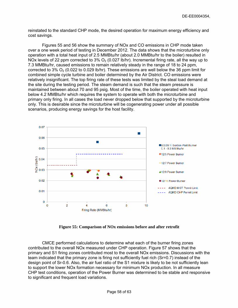
DE-EE0004354,
reinstated to the standard CHP mode, the desired operation for maximum energy efficiency and cost savings.
Figures 55 and 56 show the summary of NOx and CO emissions in CHP mode taken
over a one week period of testing in December 2012. The data shows that the microturbine only operation with a total heat input of 2.5 MMBtu/hr (about 2.0 MMBtu/hr to the boiler) resulted in NOx levels of 22 ppm corrected to 3% O2 (0.027 lb/hr). Incremental firing rate, all the way up to 7.3 MMBtu/hr, caused emissions to remain relatively steady in the range of 18 to 24 ppm, corrected to 3% O2 (0.022 to 0.029 lb/hr). These emissions are well below the 36 ppm limit for combined simple cycle turbine and boiler determined by the Air District. CO emissions were relatively insignificant. The top firing rate of these tests was limited by the steal load demand at the site during the testing period. The steam demand is such that the steam pressure is maintained between about 70 and 95 psig. Most of the time, the boiler operated with heat input below 4.2 MMBtu/hr which requires the system to operate with both the microturbine and primary only firing. In all cases the load never dropped below that supported by the microturbine only. This is desirable since the microturbine will be cogenerating power under all possible scenarios, producing energy savings for the host facility.
Figure 55: Comparison of NOx emissions before and after retrofit
CMCE performed calculations to determine what each of the burner firing zones contributed to the overall NOx measured under CHP operation. Figure 57 shows that the primary and S1 firing zones contributed most to the overall NOx emissions. Discussions with the team indicated that the primary zone is firing not sufficiently fuel rich (Sr=0.7) instead of the design point of Sr-0.6. Also, the air fuel ratio of the S1 mixture is likely to be not sufficiently lean to support the lower NOx formation necessary for minimum NOx production. In all measure CHP test conditions, operation of the Power Burner was determined to be stable and responsive to significant and frequent load variations.
Page 58 of 63
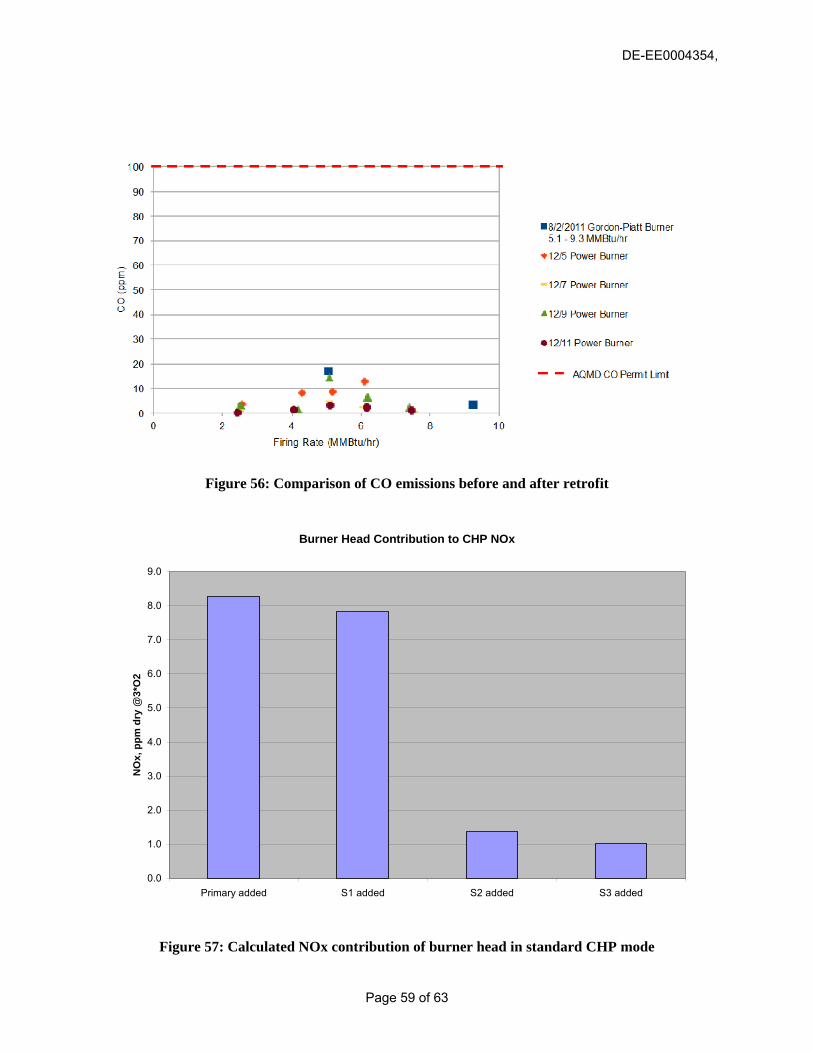
DE-EE0004354,
Figure 56: Comparison of CO emissions before and after retrofit
Burner Head Contribution to CHP NOx
0.0
1.0
2.0
3.0
4.0
5.0
6.0
7.0
8.0
9.0
Primary added S1 added S2 added S3 added
NO
x, p
pm d
ry @
3*O
2
Figure 57: Calculated NOx contribution of burner head in standard CHP mode
Page 59 of 63

DE-EE0004354,
Figure 57 summarizes the energy changes for the boiler operating with the original Gordon Piatt burner and with the retrofitted Power during three load settings: low fire (about 4MMBtu/hr), medium fire ( about 5 MMBtu/hr), and high fire (about 7.3 MMBtu/hr). For the low fire condition, the boiler efficiency decreased by 3 percentage points. This is because the microturbine provides additional flow exhaust compared to the original burner. For both medium and high fire conditions, the Power Burner resulted in an increase in boiler efficiency by about 1 to 3.5 percentage points, as more of the air in the microturbine exhaust was being used by the burner. This is significant in that if the boiler steam demand can be maintained at these medium to high fire conditions, the cost savings associated with the 100 kW electrical generation of the Power Burner can be readily augmented by an additional $2,600 to $9,000 per year.
5/11/2010 SCG Tuneup
Gordon-Piatt Burner
12/7/12 Leva MeasurementsLeva Power Burner
Thermal Input (MMBtu/hr) 2.47
Stack Temperature (F) 410
Stack O2% 15.3
Reported Combustion EfficiencyCombustion Efficiency—SCG Spreadsheet(100%-Stack Losses, per ANSI Z21.13) 69.1%
Thermal Input (MMBtu/hr) "Low" 4.03
Stack Temperature (F) 452.7 500
Stack O2% 10.7% 11.4
Reported Combustion Efficiency 78.4%Combustion Efficiency—SCG Spreadsheet(100%-Stack Losses, per ANSI Z21.13) 76.3% 73.3%
MG
T-O
nly
Low
Fire
5/11/2010 SCG Tuneup
Gordon-Piatt Burner
12/7/12 Leva MeasurementsLeva Power Burner
Thermal Input (MMBtu/hr) "Mid" 5.03
Stack Temperature (F) 539.3 543
Stack O2% 9.7% 8.7
Reported Combustion Efficiency 76.6%Combustion Efficiency—SCG Spreadsheet(100%-Stack Losses, per ANSI Z21.13) 73.9% 75.1%
Thermal Input (MMBtu/hr) "High" 7.32
Stack Temperature (F) 573.2 589
Stack O2% 8.0% 3.0%
Reported Combustion Efficiency 77.5%Combustion Efficiency—SCG Spreadsheet(100%-Stack Losses, per ANSI Z21.13) 74.6% 78.0%
Mid
Fire
Hig
h Fi
re
Figure 58: Pre- and post-retrofit boiler efficiency changes
Page 60 of 63

DE-EE0004354,
3.0 PRODUCTS 3.1 Publications The project team did not participate in any conferences that displayed the results or detailed results of the technology development or application. However, the project team made several presentations to potential investors, whose list is proprietary, to highlight the technology and the financial benefits of its application in the industrial and commercial boiler markets. The CMCE Principal Investigator also submitted written responses to the DOE on the efforts and progress to commercialize the technology along with marketing analyses and other proprietary material. This information was submitted in confidence and with strict guidelines on review only by the US DOE and its employees 3.2 Web Site The project team of CMCE and Altex financed the publication of a Web site under the commercial name of Leva Energy (www.levaenergy.com
DEVELOPED
) for the sole purpose of informing the public and potential investors of the availability of the Power Burner technology for sale, demonstration, and for investment. 3.3 Networks and Collaborations In an effort to commercialize the technology, CMCE and Altex, principally through the fostered collaboration developed in the investment made into Leva Energy, was able to establish a significant network consisting of equipment suppliers, sales representatives, potential investors, and industrial original equipment manufacturers (OEMs) that have shown interest in cooperating in the supply of key Power Burner components; offering sites for demonstrations; conditional purchases of the system; marketing and sales in various key industrial states. These contacts remain proprietary to the commercial development effort and were listed in the confidential document supplied to the DOE upon their request. 3.4 Technologies and Techniques The DOE project served to address key upgrades and equipment modifications necessary to convert T-100 Turbec microturbines to simle cycle configurations and to integrate the exhaust flow in such a manner to provide the operating flexibility necessary to maintain reliability and flexible load operation, so vital in industrial and commercial steam and hot water boilers. This adaptation also included the burner management system (BMS) supplied by Fireye so that it can provide the additional controls necessary to monitor and operate the Power burner in a user friendly control environment. 3.5 Inventions and Patents The Principal Investigators at CMCE and its subcontractor, Altex, filed a provisional patent on June 11, 2010, prior to the start of the work under this DOE Grant. The process patent application was based on the process originally demonstrated by CMC-Engineering in 2009 under a California Energy Commission project but with the integration of the patented Altex burner technology operating with a simple cycle microturbine so that both microturbine exhaust and boiler emissions could be managed and optimized to permit load following and emission
Page 61 of 63

DE-EE0004354,
compliance with strict California based air quality standards and Air District rules. As of the date f this writing, the patent has not been awarded.
3.5 Other Products
ds
o The project included selective modeling of key operating systems. This was necessary to address the complexities of concurrent microturbine and burner operation. These analyses culminated in the approach selected to handle hot microturbine exhaust and burner operation while maintaining emissions in compliance with local Air District rules. These data and methoemployed in these modeling efforts are considered proprietary.
Page 62 of 63

DE-EE0004354,
4.0 CONCLUSIONS The concept of integrating a simple cycle microturbine with a low NOx gas-fired burner
r industrial and commercial size packaged boilers has been further validated with the
a, CA achieved all its erformance objectives and most of the planned technical goals and continues in operation avings energy and money for the hotel. It is estimated that the hotel reduces its energy
consumption .by 2,000 to 5,000 MMBtu/yr, indirectly by generating onsite power more efficiently than either modern combined cycle or older Rankine cycle central stations. This results in a reduction in carbon footprint by 120 to 300 tons/yr. In addition the boiler efficiency can be improved by 1 to 3.5 percentage points, adding approximately 440 to 1,500 MMBtu/yr of energy savings an additional reduction in CO2 of 26 to 90 ton/yr. The Westin is currently saving $117,000/yr in electricity cost based on 4,250 Btu/kWh microturbine heat rate, a natural gas cost of $6/MMBtu, and a current electricity rate of $0.16/kWh.
fodevelopment and demonstration of the Power Burner. The concept was originally introduced byCMCE and Coen Company with a successful demonstration at the Hitachi plant in San Jose, CA using a modified Elliott microturbine and a QLN Coen burner. The Power Burner was developed with a modified Turbec 100 kW microturbine and an Altex low NOx burner. The installation of the Power Burner at the Westin hotel in Costa Mesps
Page 63 of 63