chp ready guidance for combustion and energy from waste … · 2014-03-26 · chp ready guidance...
TRANSCRIPT
Title here in 8pt Arial (change text colour to black) i
CHP Ready Guidance for Combustion and Energy from Waste Power Plants V1.0 February 2013

ii CHP Ready Guidance for Combustion and Energy from Waste Power Plants
We are the Environment Agency. We protect and improve the environment and make it a better place for people and wildlife. We operate at the place where environmental change has its greatest impact on people’s lives. We reduce the risks to people and properties from flooding; make sure there is enough water for people and wildlife; protect and improve air, land and water quality and apply the environmental standards within which industry can operate. Acting to reduce climate change and helping people and wildlife adapt to its consequences are at the heart of all that we do. We cannot do this alone. We work closely with a wide range of partners including government, business, local authorities, other agencies, civil society groups and the communities we serve.
Published by: Environment Agency Horizon House, Deanery Road Bristol BS1 5AH Email: [email protected] www.environment-agency.gov.uk © Environment Agency 2011 All rights reserved. This document may be reproduced with prior permission of the Environment Agency.
Further copies of this report are available from our publications catalogue: http://publications.environment-agency.gov.uk or our National Customer Contact Centre: T: 03708 506506

CHP Ready Guidance for Combustion and Energy from Waste Power Plants iii
List of Abbreviations Abbreviation
Description
AQMA Air Quality Management Area BAT Best Available Techniques BREF BAT Reference Document CBA Cost Benefit Analysis CCR Carbon Capture Ready / Carbon Capture Readiness CCS Carbon Capture and Storage CHP Combined Heat and Power CHP-R Combined Heat and Power Ready DECC Department of Energy and Climate Change DCO Development Consent Order DUKES Digest of United Kingdom Energy Statistics EED Energy Efficiency Directive EfW Energy from Waste ELV Emission Limit Value EU European Union GWh Gigawatt hours HHV Higher Heating Value IED Industrial Emissions Directive IPPC Integrated Pollution Prevention and Control km Kilometres kW Kilowatts LCPD Large Combustion Plant Directive MW Megawatts NPPF National Planning Policy Framework NPS National Policy Statement PPC Pollution Prevention and Control SEPA Scottish Environment Protection Agency UK United Kingdom

iv CHP Ready Guidance for Combustion and Energy from Waste Power Plants
Contents 1 Introduction 5 1.1 Benefits of Combined Heat and Power 5 1.2 CHP in the UK 8 1.3 Potential for Good Quality CHP 8 1.4 Incentives and Support Mechanisms for CHP in the UK 9 1.5 Information on CHP in the UK 9
2 Policy, Regulation and Guidance concerning CHP 10 2.1 The Industrial Emissions Directive and use of BAT 10 2.2 The Energy Efficiency Directive 11 2.3 The Waste Framework Directive 12
3 Consideration of CHP in Planning 13 3.1 Planning Policies concerning CHP 13 3.2 Development Consent Orders 13 3.3 The Environment Agency's Role as a Consultee to the Planning Process 14
4 CHP-R Assessment 16 4.1 Requirement 1: Plant, Plant Location and Potential Heat Loads 16 4.2 Requirement 2: Identification of ‘CHP Envelope’ 17 4.3 Requirement 3: Operation of Plant with the Identified Heat Load 19 4.4 Requirement 4: Technical Provisions and Space Requirements 19 4.5 Requirement 5: Integration of CHP and Carbon Capture 20 4.6 Requirement 6: Economics of CHP-R 21
5 BAT Assessment 22
Appendix A: CHP-R Assessment Form 24
Appendix B: Case Studies / Worked Examples 40 Case Study / Worked Example 1 41 Case Study / Worked Example 2 50 Case Study / Worked Example 3 59 Case Study / Worked Example 4 68 Case Study / Worked Example 5a 77 Case Study / Worked Example 5b 85
Appendix C: Additional Economic Supporting Information 94 Qualitative Economic Screening 94 Economics of CHP-R and CHP 95
Appendix D: Additional Technical Supporting Information 99 Large Scale Conventional Steam Plant with Reheat (Water Cooled Surface
Condenser) 100

CHP Ready Guidance for Combustion and Energy from Waste Power Plants v
Large Scale CCGT Plant with Reheat (Water Cooled Surface Condenser) 101 Small Scale Conventional Steam Plant with Reheat (Water Cooled Surface Condenser)102 Small Scale Conventional Steam Plant without Reheat (Water Cooled Surface
Condenser) 103 Small Scale CCGT Plant without Reheat (Water Cooled Surface Condenser) 104

CHP Ready Guidance for Combustion and Energy from Waste Power Plants 1
Foreword The Environment Agency requires that all applications for Environmental Permits for new installations regulated under the Environmental Permitting (England and Wales) Regulations 2010 demonstrate the use of Best Available Techniques (BAT) for a number of criteria, including energy efficiency. One of the principal ways in which energy efficiency can be improved is through the use of Combined Heat and Power (CHP). With respect to the use of CHP, there are three BAT tests which should be applied. These are as follows: First BAT Test: The Environment Agency considers that BAT for energy efficiency for new combustion power plant or Energy from Waste (EfW) plant is the use of CHP in circumstances where there are technically and economically viable opportunities for the supply of heat from the outset. The term CHP in this context represents a plant which also provides a supply of heat from the electrical power generation process to either a district heating network or to an industrial / commercial building or process. However, it is recognised that opportunities for the supply of heat do not always exist from the outset (i.e. when a plant is first consented, constructed and commissioned). Second BAT Test: In cases where there are no immediate opportunities for the supply of heat from the outset, the Environment Agency considers that BAT is to build the plant to be CHP-Ready (CHP-R) to a degree which is dictated by the likely future opportunities which are technically viable and which may, in time, also become economically viable. The term ‘CHP-R’ in this context represents a plant which is initially configured to generate electrical power only but which is designed to be ready, with minimum modification, to supply heat in the future. The term 'minimum modification' represents an ability to supply heat in the future without significant modification of the original plant / equipment1. Given the uncertainty of future heat loads, the initial electrical efficiency of a CHP-R plant (before any opportunities for the supply of heat are realised) should be no less than that of the equivalent non-CHP-R plant. For these cases, the Environment Agency has developed this CHP-R Guidance to be used for applications for Environmental Permits for new plants under the Environmental Permitting (England and Wales) Regulations 2010. Third BAT Test: Once an Environmental Permit has been issued for a new CHP-R plant, the applicant / operator should carry out periodic reviews of opportunities for the supply of heat to realise CHP. Such opportunities may be created both by new heat loads being built in the vicinity of the plant, and / or be due to changes in policy and financial incentives which improve the economic viability of a heat distribution network for the plant being CHP. 1 Further information in this regard is provided in Section 4 (CHP-R Assessment).

2 CHP Ready Guidance for Combustion and Energy from Waste Power Plants
Use of the CHP-R Guidance Insert 1 illustrates the three BAT tests (i.e. the BAT Assessment process for CHP and CHP-R) and shows how this CHP-R Guidance should be used.
INSERT 1: BAT ASSESSMENT PROCESS FOR CHP AND CHP-R

CHP Ready Guidance for Combustion and Energy from Waste Power Plants 3
As described above, this CHP-R Guidance should primarily be used to help satisfy the requirements of the second BAT test. However, elements of this CHP-R Guidance may also be relevant to the first and third BAT tests. For example, whilst a new plant may incorporate CHP at the outset, there may still be opportunities for the supply of additional heat in the future. In this case, it may also be appropriate for the new plant to incorporate a number of elements of CHP-R. Furthermore, it should also be noted that whilst the primary focus of this CHP-R Guidance is on the demonstrations required in an application for an Environmental Permit, the principles contained within may also have implications on Development Consent Order (DCO) applications for new plant. Therefore, it is recommended that this CHP-R Guidance (and the requirements for CHP-R) is also considered prior to making a DCO application, in particular because the first and second BAT tests may affect the layout, space requirements and building design for the implementation of CHP. Additionally, the Planning Authority may take into account the ability of the new plant to supply heat as part of its assessment on whether the development constitutes an appropriate use of land. In this regard, the Environment Agency may also provide comments to the Planning Authority on the suitability of the location for the new plant with respect to potential heat loads, with an emphasis on co-locating heat sources and loads wherever possible. In this respect, the Environment Agency anticipates that new EfW plants are likely to have greater flexibility in terms of their location than new combustion power plants. However, new combustion power plants will generally be able to apply a wider search radius for economic opportunities for the supply of heat by virtue of their far greater potential heat output2.
2 Further information in this regard is provided in Section 3 (Consideration of CHP in Planning).

4 CHP Ready Guidance for Combustion and Energy from Waste Power Plants
Applicability of the CHP-R Guidance This CHP-R Guidance applies to applications for Environmental Permits under the Environmental Permitting (England and Wales) Regulations 2010 for:
• New combustion power plants (referred to as power plants) with a gross rated thermal input of 50 or more MegaWatts (MW); and
• New EfW plants with a throughput of more than 3 tonnes per hour of non-hazardous waste or 10 tonnes per day of hazardous waste.
Accordingly, this CHP-R Guidance is applicable to:
• Applicants / operators for new plants such that they can:
- Provide sufficient information to the Environment Agency in an application for an Environmental Permit to demonstrate BAT for a new plant which uses CHP at the outset or is designed to be CHP-R;
- In the case of a CHP-R plant, show that the new plant is designed to be ready, with minimum modification, to supply heat in the future;
- In the case of a CHP-R plant, make adequate technical provisions such that the new plant is ready, with minimum modification, to supply heat in the future; and,
- Carry out periodic reviews of opportunities for the supply of heat.
• The Environment Agency when assessing an application for an Environmental Permit for a new plant which uses CHP at the outset or is designed to be CHP-R.
For any application under the Environmental Permitting (England and Wales) Regulations 2010 which includes combustion power plant for supplying heat, the Environment Agency would expect the use of CHP to be considered and implemented (wherever practicable) in line with principles described in the Draft H2 Energy Efficiency Guidance. In addition, whilst it is considered that CHP is technically feasible for all types of new plants, it is recognised that in some cases (such as peaking plant and anaerobic digestion plants) the provision of CHP would not be compatible with original operating regimes / intentions. Therefore, in such cases, applicants for Environmental Permits should provide evidence as to why their plant should be excluded from being CHP-R.

CHP Ready Guidance for Combustion and Energy from Waste Power Plants 5
1 Introduction CHP is the generation of electrical power and usable heat in a single process. This is also known as cogeneration. CHP is a well proven technology for reducing primary energy usage (hence providing primary energy savings) and reducing carbon emissions.
1.1 Benefits of Combined Heat and Power Generating electrical and heat together in a CHP plant is more efficient than generating them separately, thus delivering a reduction in both primary energy usage and carbon emissions. This is demonstrated by the following cases which considers a site that has a requirement for 120 MW of electrical power and 180 MW of heat. This could be:
• Separately supplied by a stand-alone plant (for the electrical power) and a stand-alone boiler plant (for the heat); or
• Supplied by a CHP plant.
This is demonstrated for a typical Combined Cycle Gas Turbine (CCGT) power plant in Case 2a and for a typical EfW plant in Case 2b. These cases are illustrated in Insert 2.

6 CHP Ready Guidance for Combustion and Energy from Waste Power Plants
INSERT 2: ILLUSTRATION OF THE PRIMARY ENERGY SAVINGS RESULTING FROM THE USE OF CHP
Case 2a: Consideration of a Typical CCGT Power Plant
Case 2a assumes that:
• CCGT power plant supplying 500 MW of electrical power has an efficiency of 60%, therefore an energy input of 833 MW;
• Stand-alone boiler plant supplying 180 MW of heat has an efficiency of 90%, therefore an energy input of 200 MW; and,
• CHP plant supplying 680 MW has an efficiency of 70%, therefore an input of 971 MW.
In this example, using a CHP plant (to replace the separate CCGT power plant and stand-alone boiler plant) would represent a primary energy saving of approximately 6%. This corresponds to an energy saving of approximately 62 MW.

CHP Ready Guidance for Combustion and Energy from Waste Power Plants 7
INSERT 2: ILLUSTRATION OF THE PRIMARY ENERGY SAVINGS RESULTING FROM THE USE OF CHP
Case 2b: Consideration of a Typical EfW Plant
Case 2b assumes that:
• Stand-alone EfW plant supplying 50 MW of electrical power has an efficiency of 33%, therefore an energy input of 152 MW;
• Stand-alone boiler plant supplying 50 MW of heat has an efficiency of 90%, therefore an energy input of 56 MW; and,
• CHP plant supplying 100 MW has an efficiency of 55%, therefore an input of 182 MW.
In this example, using a CHP plant (to replace the separate EfW plant and stand-alone boiler plant) would represent a primary energy saving of approximately 12%. This corresponds to an energy saving of approximately 25 MW.

8 CHP Ready Guidance for Combustion and Energy from Waste Power Plants
In addition, whilst the corresponding savings in carbon dioxide emissions would depend on the fuels used in the CHP plant, and the fuels displaced from the separate stand-alone plant, they are considered to be both substantial and significant.
1.2 CHP in the UK Unlike many other European countries, the UK does not have widely developed infrastructure for heat. This is due to a number of constraints, both regulatory and financial in nature. These constraints have meant that, in the UK, there has been limited consideration given in the selection of locations for new plants to areas with high heat demand densities (i.e. where CHP schemes could be more readily established). Improved incentives and support measures could see an increased amount of realised CHP schemes and a new market opening up for infrastructure / networks for heat in the future. With such a new market, similar to many other European countries, CHP schemes would likely be based on bespoke CHP plants which are designed to supply electricity and heat right from the outset. However, as an infrastructure / network for heat is not available on a wide scale in the UK, basing new plants on such a model is unlikely to be suitable. Until such a time when wide scale infrastructures / networks for heat are available in the UK, it is prudent to ensure that new plants which are initially required to generate electrical power only have included sufficient flexibility in their design to be ready (without significant modification) to supply heat in the future as and when opportunities become available. In allowing sufficient flexibility in their design to be ready to supply heat in the future, new plants could be considered CHP-R and ‘CHP Lockout’ (where a plant cannot supply heat without significant modification) can be avoided.
1.3 Potential for Good Quality CHP In recognition of the role that CHP can play in meeting the UK’s Energy Policy priorities, the Government has committed to promoting 'Good Quality CHP'. Good Quality CHP is that which has been certified as highly efficient under the CHP Quality Assurance Programme and, in accordance with the European Union (EU) Energy Efficiency Directive (Directive 2012/27/EU), achieves at least 10% primary energy savings. Based on information given in DUKES3, in 2011 there were 1,880 Good Quality CHP schemes in the UK with an electrical capacity of 6.111 GigaWatts (GW). The corresponding electrical power and heat generation was 27 191 GigaWatt hours (GWh) and 48 627 GWh respectively, providing an estimated 13.97 Mt of carbon dioxide savings. This is equivalent to the annual carbon dioxide output of 2.3 GW of CCGT power plant electrical power generation, or 5.3 GW of super-critical coal power plant electrical power generation, both operating with a 90% capacity factor. However, it is recognised that more can be done and that there is a cost-effective potential for a doubling of Good Quality CHP by 20204.
3 Available at: http://www.decc.gov.uk/en/content/cms/statistics/publications/dukes/dukes.aspx# 4 Further information in this regard is provided in Section 4 (CHP-R Assessment).

CHP Ready Guidance for Combustion and Energy from Waste Power Plants 9
1.4 Incentives and Support Mechanisms for CHP in the UK Depending on the type of plant proposed, there are a variety of incentives and support measures for plants which incorporate CHP in the UK. For example5:
• Up to 1 April 2013, exemption (via Levy Exemption Certificates) from the Climate Change Levy of all fuel inputs to (and electricity outputs from) Good Quality CHP;
• Enhanced Capital Allowances for Good Quality CHP equipment / machinery in Non-Utility Sectors;
• Business Rates exemption for embedded CHP equipment / machinery; and,
• Support under the Renewables Obligation and / or Renewables Heat Incentive6 for some types of plant that incorporate CHP. .
However, it should be noted that the above measures may be subject to change as a result of changes in Government Policy. Therefore, it may be that additional incentives and support measures for plants which incorporate CHP may be available in the future.
1.5 Information on CHP in the UK Information on CHP in the UK can be found on the CHP Focus Website at: http://chp.decc.gov.uk/cms/ This website contains comprehensive information on all aspects of CHP. The website also contains a link to the UK CHP Development Map, which can be found at: http://chp.decc.gov.uk/developmentmap/ This website provides a useful search tool at the initial planning and pre-application stage when searching for the likely extent and nature of CHP opportunities (i.e. potential heat loads) in the area surrounding the new plant.
5 Adapted from Digest of UK Energy Statistics (DUKES) 2011 – Chapter 6 (Combined Heat and Power). 6 At the time of writing, DECC are intending to consult on amendments to the Renewable Heat Incentive (RHI) tariff arrangements for renewable CHP plants which are not eligible for the "half Renewable Obligation Certificates uplift" which applies to plant accredited before 1 April 2013.

10 CHP Ready Guidance for Combustion and Energy from Waste Power Plants
2 Policy, Regulation and Guidance concerning CHP The following Section considers the main aspects of existing Policy, Regulations and Guidance concerning CHP, including:
• The Industrial Emissions Directive and use of BAT;
• The Energy Efficiency Directive; and
• The Waste Framework Directive.
2.1 The Industrial Emissions Directive and use of BAT In November 2011, the EU adopted Directive 2010/75/EU on industrial emissions (the Industrial Emissions Directive (IED)). The IED entered into force in January 2012. The IED recasts seven existing EU Directives related to industrial emissions into a single instrument to improve the permitting, compliance and enforcement regimes adopted by Member States. In particular, the IED incorporated the requirements of two existing EU Directives.
• Directive 2008/1/EC concerning integrated pollution prevention and control (the Integrated Pollution Prevention and Control Directive (IPPC Directive))
The purpose of the IPPC Directive was to achieve integrated prevention and control of pollution arising from certain potentially polluting processes and to ensure a high level of protection for the environment taken as a whole. Measures were laid down to prevent or, where that was not practicable, reduce emissions in the air, water and land introducing Emissions Limit Values (ELV) and Best Available Techniques (BAT). With regard to plants, combustion installations with a rated thermal input exceeding 50 MW were subject to the IPPC Directive.
• Directive 2001/80/EC on the limitation of emissions of certain pollutants into the air from large combustion plants (the Large Combustion Plant Directive (LCPD))
The purpose of the LCPD was to limit the emissions of certain pollutants (including oxides of nitrogen, sulphur dioxide and particulates) into the atmosphere from large combustion processes by imposing ELVs. With regard to plants, combustion installations with a rated thermal input exceeding 50 MW were subject to the LCPD. The IED is intended to achieve a high level of protection for the environment and human health while simplifying the existing legislation and cutting unnecessary administrative costs. The IED makes provisions for the continuation of the requirements and principles of the IPPC Directive and the LCPD and introduces new, more stringent, ELVs with full compliance by existing plants required by 1 January 20167. Member States are required to enact the IED by 7 January 2013. 7 However, the operator may take one of the "bounded flexibilities" available through Chapter III of the IED.
CHP Ready Guidance for Combustion and Energy from Waste Power Plants 11
The Environmental Permitting (England and Wales) Regulations 2010 currently transpose the IPPC Directive and the LCPD into UK Legislation. Amendments to these Regulations are proposed to transpose the IED into UK Legislation. With regards to BAT, the IPPC Directive required that there was an information exchange between Member States and the industries concerned, and that the results of this information exchange be published every three years. The EU IPPC Bureau published the latest BAT Reference Document (BREF) for Large Combustion Plants (Large Combustion Plant BREF) in July 2006. The IED retains the requirement for information exchange and also goes further in specifying that the Reference Documents should be updated as least every 8 years. As part of a comprehensive contribution to the on-going update for the Large Combustion Plant BREF, the UK Technical Working Group (of which the Environment Agency is a member) submitted a summary of the UK position for BAT for new and existing plants in May 2011. As previously stated, CHP is a well proven technology for reducing primary energy usage (hence providing primary energy savings) and reducing carbon dioxide emissions. For this reason, the UK submission states that BAT for energy efficiency for a plant is the use of CHP where there are economically viable opportunities for the supply of heat from the outset. Where there are no opportunities for the supply of heat from the outset, BAT for energy efficiency is CHP-R. Further to this, the LCPD required applicants for Environmental Permits to examine the technical and economic feasibility of CHP. Based on this requirement, the Environment Agency’s H2 Energy Efficiency Guidance recommends the use of CHP where opportunities exist. Where opportunities exist, the H2 Energy Efficiency Guidance includes a methodology for assessing the feasibility of CHP, including a Cost-Benefit Analysis of the available opportunities.
2.2 The Energy Efficiency Directive In October 2012, the EU adopted Directive 2012/27/EU on energy efficiency (the Energy Efficiency Directive (EED)). The EED aims to establish a common framework of measures for the promotion of energy efficiency within the Union in order to ensure the achievement of the Union's 2020 20% headline target on energy efficiency and to pave the way for further energy efficiency improvements beyond that date. In addition, the EED lays down rules designed to remove barriers in the energy market and overcome market failures that impede efficiency in the supply and use of energy, and provide for the establishment of indicative national energy efficiency targets for 2020. Of relevance to this CHP-R Guidance, the EED repeals Directive 2004/8/EC on the promotion of cogeneration based on a useful heat demand in the internal energy market (the Cogeneration Directive). In terms of CHP (or co-generation), the EED states (at Paragraph 35) that "high efficiency cogeneration and district heating and cooling has significant potential for saving primary energy, which is largely untapped in the Union. Member States should carry out a comprehensive assessment of the potential for high-efficiency cogeneration and district heating and cooling. These assessments should be updated, at the request of the Commission, to provide investors with information concerning national development plans and contribute to a stable and supportive investment environment". The EED also states (at Paragraph 35) that "new electricity generation installations and existing installations which are substantially refurbished or whose permit or licence is updated should, subject to a cost-benefit analysis showing a cost-benefit surplus, be

12 CHP Ready Guidance for Combustion and Energy from Waste Power Plants
equipped with high-efficiency cogeneration units to recover waste heat stemming from the production of electricity". Further information is included at Article 14(5) / 14(7) (concerning installations considered to be included) and Article 14(6) / 14(8) (concerning installations considered to be excluded) of the EED. This sets the scene for the consideration of CHP opportunities (and the associated benefits) within applications. Of relevance to this CHP-R Guidance, the cost-benefit analysis is considered to represent elements of the first and second BAT tests. Furthermore, at Annex II, the EED prescribes how primary energy savings can be calculated and thus how highly-efficient cogeneration (i.e. Good Quality CHP) can be defined.
2.3 The Waste Framework Directive Of relevance to EfW plants is Directive 2008/98/EC on waste and repealing certain Directives (The Waste Framework Directive). Article 23 (Issue of Permits), Item 4 states that "it shall be a condition of any permit covering incineration or co-incineration with energy recovery that the recovery of energy take place with a high level of energy efficiency". Accordingly, this sets the scene for the consideration of CHP opportunities (and the associated benefits) within applications.

CHP Ready Guidance for Combustion and Energy from Waste Power Plants 13
3 Consideration of CHP in Planning 3.1 Planning Policies concerning CHP In England, the National Planning Policy Framework (NPPF) sets out the UK Governments Planning Policies and how they are expected to be applied by applicants at the planning stage of any development. The NPPF replaces many of the documents in the existing suite of Planning Policy Statements, Planning Policy Guidelines, Circulars and accompanying Guidance which would previously have required assessment as part of an application for a new plant. In particular of relevance to this CHP-R Guidance is the replacement of Planning and Climate Change - Supplement to Planning Policy Statement 1 (December 2007). In terms of new plants, the NPPF does not contain specific policies or considerations. However, specific policies and considerations for new plants greater than 50 MW are detailed in the framework set up through the Planning Act 2008, published in National Policy Statements (NPS). For new plants greater than 50 MW, the following NPS are likely to be relevant:
• EN-1 Overarching Energy NPS;
• EN-2 Fossil Fuel Electricity Generating Infrastructure NPS; and
• EN-3 Renewable Energy Infrastructure NPS.
These NPS are available to download at: http://www.decc.gov.uk/en/content/cms/meeting_energy/consents_planning/nps_en_infra/nps_en_infra.aspx Within EN-1 Overarching Energy NPS, Section 4.6 details the requirements for consideration of CHP. This states (at Paragraph 4.6.12) that in the event that future CHP opportunities have been identified "the IPC [Infrastructure Planning Commission, now integrated with the Planning Inspectorate] may wish to impose requirements to ensure that the generating station is CHP-Ready unless ... [they are] satisfied that the applicant has demonstrated that the need to comply with the requirement to be Carbon Capture Ready will preclude any provision for CHP"8. For new plants less than 50 MW, the NPS are likely to be a material consideration.
3.2 Development Consent Orders In England, as part of any application for a Development Consent Order (DCO) under the Planning Act 2008 (previously Section 36 Consent under the Electricity Act 1989), applications for new plants (greater than 50 MW) must show that they have fully considered the opportunities for CHP. Typically, this is undertaken by submitting a
8 It should be noted here that this CHP-R Guidance assumes that the requirement to be Carbon Capture Ready (CCR) has not precluded any provision to be CHP-R.

14 CHP Ready Guidance for Combustion and Energy from Waste Power Plants
CHP Assessment with the application (in line with Section 4.6 of EN-1 Overarching Energy NPS) which contains details on:
• “An explanation of their choice of location, including the potential viability of the site for CHP;
• A report on the exploration carried out to identify and consider the economic feasibility of local heat opportunities and how to maximise the benefits from CHP;
• The results of that exploration; and
• A list of organisations contacted.
• And, if the proposal is for generation without CHP:
• The basis for the developer’s conclusion that it is not economically feasible to exploit existing regional heat markets;
• A description of potential future heat requirements in the area; and
• The provisions in the proposed scheme for exploiting any potential heat demand in the future”9.
For DCO granted for new plants for “generation without CHP”, the subsequent application for an Environmental Permit should build on the conclusions of the CHP Assessment and contain sufficient information to demonstrate the new plant will be built CHP-R (for the chosen location and design). This CHP-R Guidance is to be used in these instances. Additionally, whilst CHP Assessments may only require waste heat10 to be made available, being CHP-R may require both process heat and waste heat to be made available according to the likely future CHP opportunities identified.
3.3 The Environment Agency's Role as a Consultee to the Planning Process The primary focus of this CHP-R Guidance is on the demonstrations required in an application for an Environmental Permit for new plants under the Environmental Permitting (England and Wales) Regulations 2010. However, the principles contained within this CHP-R Guidance may also have implications on consent applications (i.e. Planning Permission (under the Town and Country Planning Act 1990) or a DCO (under the Planning Act 2008)) for the new plant. Indeed, the Environment Agency will be consulted on these applications, as well as applications for extensions of / variations to existing plants. The Environment Agency Document "Guidelines for Developments requiring Planning Permission and Environmental Permits" sets out the Environment Agency's role in the planning process and its approach to responding to applications for developments which will also require an Environmental Permit. In particular, these Guidelines recognise that there may be some interdependencies between planning and permitting requirements. In the case of such interdependencies, the Guidelines recommend early 9 Department of Trade and Industry’s (DTI) (now DECC) Document “Guidance on Background Information to Accompany Notifications under Section 14 (1) of the Energy Act 1976 and Applications under Section 36 of the Electricity Act 1989, December 2006” 10 One example of 'waste heat' is hot water from the cooling system which could be used as a heat source for Liquefied Natural Gas Plant Vaporisers or Greenhouses.

CHP Ready Guidance for Combustion and Energy from Waste Power Plants 15
engagement with the Environment Agency via their planning pre-application service and, in some cases, a "parallel-tracking" approach is recommended whereby the preparation and submission of the planning and permitting applications is carried out at the same time. Therefore, it is recommended that this CHP-R Guidance (and the requirements for CHP-R) is considered prior to making a consent application for a new plant, in particular because the first and second BAT tests may affect the layout, space requirements and building design for the implementation of CHP. Accordingly, the Environment Agency recommends that the requirement for new plants to be CHP or CHP-R is discussed at the earliest possible stage, ideally during planning pre-application. In any case, where a DCO is required the applicant will have to make similar demonstrations under both the planning and permitting applications in terms of suitability of the location for CHP, potential opportunities for heat supply and CHP-R. When consulted by the Planning Authorities on relevant consent applications for new plants, the Environment Agency will highlight the need for the plant to be CHP or CHP-R and will make reference to this CHP-R Guidance. Where a DCO is required, the Environment Agency will additionally comment on the results of the CHP Assessment. Where a DCO is not required, the Environment Agency will recommend to the Planning Authorities that the location of the plant with respect to potential opportunities for heat supply is considered as part of the planning process. Where the Environment Agency is aware of potential heat loads in the area, they will provide details of these to the Planning Authorities. The Environment Agency will not object to applications for new plants where they are located in areas where there are no opportunities for heat supply. However, where relevant, the Environment Agency will highlight the lack of opportunities to the Planning Authorities and this may influence the Planning Authority in its consideration of the suitability of the proposed location. When consulted on applications for modifications to existing plants (which will also require a variation to the Environmental Permit), the Environment Agency will highlight the need for the plant to be CHP or CHP-R (where relevant), but is unlikely to provide comments in the suitability of the location of the plant for CHP. Additionally, the Planning Authority may take into account the ability of the new plant to supply heat as part of its assessment on whether the development constitutes an appropriate use of land. In this regard, the Environment Agency may also provide comments to the Planning Authority on the suitability of the location for the plant with respect to potential heat loads, with an emphasis on co-locating heat sources and loads wherever possible. In this respect, the Environment Agency anticipates that new EfW plants are likely to have greater flexibility in terms of their location than new combustion power plants, while new combustion power plants will generally be able to apply a wider search radius for economic opportunities for the supply of heat by virtue of their far greater potential heat output.

16 CHP Ready Guidance for Combustion and Energy from Waste Power Plants
4 CHP-R Assessment This Section should be read in conjunction with the CHP-R Assessment Form which is provided in Appendix A. Additional Guidance Notes on the use of the CHP-R Assessment Form are also provided in Appendix A. The CHP-R Assessment should demonstrate that the new plant is designed to be ready, with minimum modification, to supply heat in the future. The term 'minimum modification' represents an ability to supply heat in the future without significant modification of the original plant / equipment. For example, a CHP-R plant will not be required to replace major items of original plant / equipment, but should retain the capability for additional plant / equipment to be installed at a later date. In this regard, the CHP-R Assessment allows for the provision of supporting information regarding any appropriate technical provisions which demonstrate that the new plant is ready to supply heat in the future. As these technical provisions are provided alongside a justification of the chosen location and selected heat loads, it is noted that the degree to which any new plant will be CHP-R will be location-specific. Therefore, BAT (under the Environmental Permitting (England and Wales) Regulations 2010) is assessed on a site-specific basis. The requirements for the CHP-R Assessment are listed in this Section. Supporting information is provided in the Appendices:
• Appendix B provides five Case Studies / Worked Examples using the CHP-R Assessment Form.
• Appendix C provides Additional Economic Supporting Information.
• Appendix D provides Additional Technical Supporting Information.
4.1 Requirement 1: Plant, Plant Location and Potential Heat Loads EN-1 - Overarching Energy NPS states that "a 2009 Report for DECC on district heating networks suggested that ... a district heating network using waste heat from a generating station would be cost-effective where there was a demand for 200 MWth of heat within 15 km". As such, it is noted that to be commercially viable for CHP, new plants should ideally be sited close to potential heat loads / heat customers with the actual distance varying with the size of the plant and the nature of the demand for heat. With this in mind, it is likely that the search radius for CHP opportunities for large combustion power plants is likely to be greater than that for a typical EfW plant. However, there is likely to be greater location flexibility for EfW plants than for large combustion power plants, potentially making it easier to co-locate EfW plants with suitable heat loads. Accordingly, wherever possible, the location criteria for selection of new plant must include the potential for immediate CHP opportunities in balance with other factors. However, it is recognised that there are often other important factors which dictate a plant’s location which may take precedence over immediate CHP opportunities. In these cases, where there are no immediate CHP opportunities, BAT is to build the power or EfW plant to be CHP-R to a degree which is dictated by the likely future opportunities which are technically viable and which may, in time, become

CHP Ready Guidance for Combustion and Energy from Waste Power Plants 17
economically viable. As such, in these cases, determining CHP-R requires consideration to be given to the likely extent and nature of future opportunities in the chosen location. This is addressed under this Requirement. Demonstrations under Requirement 1:
• A description of the plant;
• A description of plant location;
• A description of the factors influencing the selection of the plant location;
• A description of the likely extent and nature of CHP opportunities (i.e. potential heat loads) in the area (an indicative search radius of 10 km should be used for plants less than 300 MW, and 15 km for plants greater than 300 MW);
• The appropriate selection of heat loads (which must be agreed with the Environment Agency at the Environmental Permit Pre-Application Stage, or (preferably) at the pre-planning application stage) to take forwards in the CHP-R Assessment;
• A justification for the appropriate selection of heat loads; and,
• Identification of the expected supply and return requirements for the selected heat load / heat loads.
In terms of the 'appropriate selection of heat loads', regard should be given to the role that CHP can play in meeting the UK's Energy Policy priorities, particularly in terms of Good Quality CHP. As noted in Section 1.3 (Potential for Good Quality CHP), Good Quality CHP is that which achieves at least 10% primary energy savings. Therefore, the selection of heat loads should be such that, wherever possible, 10% primary energy savings could be achieved in the future. However, where this is not possible, the selection of heat loads should be such that maximum primary energy savings could eventually be achieved in the future whilst not necessarily meeting the criteria for Good Quality CHP. Accordingly, the appropriate selection of heat loads will likely include a discussion with the Environment Agency and potential heat load recipient(s), and / or a degree of qualitative economic screening. It should be noted that the heat loads for assessment must be agreed with the Environment Agency. For further information, please see Additional Economic Supporting Information in Appendix C. It should be noted that the subsequent Requirements, listed below, discuss a methodology for one selected heat load. However, if the appropriate selection of heat loads requires that more than one heat load is taken forward, then the CHP-R Assessment should be undertaken for all selected heat loads.
4.2 Requirement 2: Identification of ‘CHP Envelope’ Obtaining a supply of heat from a plant is most likely to be achieved by extracting steam from the steam cycle. Alternatively (or additionally), for some types of applications where only low grade heat is required (such as Liquefied Natural Gas Plants and Greenhouses), a supply of heat from a plant can be achieved by extracting hot water from the cooling system.

18 CHP Ready Guidance for Combustion and Energy from Waste Power Plants
A plant which is CHP will have a known heat load size and profile at the outset, and therefore an optimal design for electrical power generation with heat generation can be achieved, including optimised extraction points. A plant which is CHP-R will not have a known heat load size or profile at the outset, and therefore an optimal design for electrical power generation only should be achieved. Indeed, given the uncertainty of future heat loads, the initial electrical efficiency of a CHP-R plant (before any opportunities for the supply of heat are realised) should be no less than that of a non-CHP-R plant. Therefore, in demonstrating CHP-R, consideration needs to be given to the ability of the new plant to meet future heat loads within its likely operational profile. This consideration allows for the identification of a ‘CHP Envelope’. The CHP Envelope represents the potential operational ranges of the new plant where it could be technically feasible to operate electrical power generation with heat generation. A graphical representation of the CHP Envelope is provided in Insert 3.
INSERT 3: GRAPHICAL REPRESENTATION OF THE CHP ENVELOPE
The following explanations are given for the points on Insert 3:
• A: The minimum electrical power output with no heat load (corresponds to the minimum stable plant load, also known as Minimum Stable Generation).
• B The minimum electrical power output at the maximum heat load (corresponds to the minimum stable plant load).
• Line A to B: The minimum electrical power output for any given heat load (corresponds to the minimum stable plant load).
• C: The maximum electrical power output at the maximum heat load (corresponds to 100% plant load).
• D: The maximum electrical power output with no heat load (corresponds to 100% plant load).

CHP Ready Guidance for Combustion and Energy from Waste Power Plants 19
• Line D to C: The maximum electrical power output for any given heat load (corresponds to 100% plant load).
• E: Proposed operational point of the plant.
• Unrestricted Operation: If a selected heat load is located in this region, the plant will have the ability to operate at any load between minimum stable plant load and 100% plant load (i.e. is not load restricted).
• Restricted Operation: If a selected heat load is located in this region, the plant will not have the ability to operate over its full operational range (i.e. is load restricted).
This is addressed under this Requirement. Demonstrations under Requirement 2: Identification of:
• The potential heat extraction at 100% Plant Load, and the effects on the plant;
• The potential heat extraction at Minimum Stable Plant Load, and effects on the plant; and,
• Whether the plant can supply the selected heat load.
4.3 Requirement 3: Operation of Plant with the Identified Heat Load Within the identified CHP Envelope, the effect of the selected heat load on the proposed operation of the plant should be determined. This is addressed under this Requirement. Demonstrations under Requirement 3: Identification of:
• The likely effects of the selected heat load on the plant.
4.4 Requirement 4: Technical Provisions and Space Requirements Determination of the effect of the selected heat load on the operation of the plant (under Requirement 3) will have required suitable extraction points to be identified. These extraction points should be described under this Requirement. Furthermore, determination of the CHP Envelope (under Requirement 2) will allow for consideration to be given to potential options which could be incorporated into the plant (either within the initial design or at a later stage) should a CHP opportunity be realised outside the identified CHP Envelope (i.e. outside the potential operating ranges of the plant).

20 CHP Ready Guidance for Combustion and Energy from Waste Power Plants
The potential options should be described under this Requirement. In addition, within the demonstration of CHP-R for all opportunities, it is important that consideration is given to the provision of additional space which may be needed. This is addressed under this Requirement. Demonstrations under Requirement 4:
• Identification of likely suitable extraction points in the plant for the identified heat load. Additional Technical Supporting Information is provided in Appendix D;
• Identification of the potential options which could be incorporated in the plant, should the CHP opportunity be realised outside the identified CHP Envelope;
• Description of how the future costs and burdens associated with supplying the identified heat load / potential CHP opportunity have been minimised through the implementation of an appropriate CHP-R design; and,
• Provision of site layout plan of the plant, indicating available space which could be made available for CHP.
4.5 Requirement 5: Integration of CHP and Carbon Capture Through the EU Directive on the geological storage of carbon dioxide (Directive 2009/31/EC) (the Carbon Capture and Storage (CCS) Directive), it is now required that developers of new plants with an electrical power output of 300 MW or more carry out an assessment to determine whether the plant is Carbon Capture Ready (CCR). Based on this requirement, current UK Policy now stipulates that “no power station at or over 300 MW ... would be consented unless it could demonstrate it would be CCR”11. Therefore, for plants with an electrical power output at or over 300 MW, consideration should be given to the ability of the plant to satisfy the requirements of CCR in conjunction with CHP-R12. This consideration allows for the identification of a ‘CHP and Carbon Capture Envelope’. The CHP and Carbon Capture Envelope represents the likely range for the operation of the new plant with carbon capture where it could be technically feasible to operate electrical power generation with carbon capture and heat generation at a later date. Determination of the CHP and Carbon Capture Envelope will allow for consideration to be given (either within the initial design or at a later stage) to: options for useful integration of the two systems; or, potential options which could be incorporated into the plant with carbon capture should a CHP opportunity be realised outside the identified CHP and Carbon Capture Envelope (i.e. outside the operating capability of the plant with carbon capture). This is addressed under this Requirement. Demonstrations under Requirement 5:
11 Carbon Capture Readiness (CCR): A Guidance Note for Section 36 Electricity Act, 1989 Consent Applications. Crown Copyright URN 09D/819. 12 For power plants with an electrical power output of less than 300 MW, no demonstrations under this Requirement are necessary.

CHP Ready Guidance for Combustion and Energy from Waste Power Plants 21
Identification of:
• The expected supply and return requirements identified for carbon capture13;
• The effects of carbon capture on the operation of the plant;
• The CHP and Carbon Capture Envelope including:
- The potential heat extraction at 100% Plant Load, and the effects on the plant.
- The potential heat extraction at Minimum Stable Plant Load, and effects on the plant.
- Identification of whether the plant with carbon capture can supply the selected identified heat load.
- Identification of the potential options which could be incorporated into the plant for useful integration of any realised CHP system and carbon capture system.
4.6 Requirement 6: Economics of CHP-R An integral part of any BAT test is a consideration of the economic viability of the chosen option. With regard to the second BAT test, the economic viability is dictated by the potential future opportunities for heat supply and the:
• Associated potential future revenues / benefits; and,
• Likely additional initial costs of making the new plant CHP-R for the selected potential future opportunities for heat supply.
Therefore, in addition to the technical assessments of CHP-R (Requirement 2 to Requirement 5), applications for an Environmental Permit for a CHP-R plant should also conduct a high level economic assessment. The high level economic assessment may build on the results of the qualitative economic screening (if completed under Requirement 1) and demonstrate, for the selected potential future opportunity for heat supply, the associated potential future revenues / benefits and likely additional initial costs for the plant to be CHP-R. For further information, please see Additional Economic Supporting Information in Appendix C.
13 For the majority of new power plants which are required to demonstrate CCR, post-combustion carbon capture technology is referenced. For this carbon capture technology is it likely that a supply of low pressure steam will be required.

22 CHP Ready Guidance for Combustion and Energy from Waste Power Plants
5 BAT Assessment In cases where there are no immediate opportunities for the supply of heat from the outset, the Environment Agency considers that BAT is to build a new plant to be CHP-R to a degree which is dictated by the foreseeable future opportunities which are technically viable and which may, in time, become economically viable. Therefore, based on the CHP-R Assessment, there should be an identification of the extent to which the new plant will be CHP-R and thus whether the proposals represent BAT. Within this CHP-R Guidance, the term BAT is considered to have the same definition at that under the IED (given at Article 3 (Definitions), Item 10). This definition is: "'Best available techniques' means the most effective and advanced stage in the development of activities and their methods of operation which indicates the practical suitability of particular techniques for providing the basis for emission limit values and other permit conditions designed to prevent and, where that is not practicable, to reduce emissions and the impacts on the environment as a whole:
(a) 'techniques' includes both the technology used and the way in which the installation is designed, built, maintained, operated and decommissioned;
(b) available techniques' means those developed on a scale which allows implementation in the relevant industrial sector, under economically and technically viable conditions, taking into consideration the costs and advantages, whether or not the techniques are used or produced in the Member State in question, as long as they are reasonably accessible to the operator;
(c) 'best' means most effective in achieving a high general level of protection of the environment as a whole".
The BAT Assessment (including consideration of the economic viability14) should include:
• A basic description of the proposed plant;
• A description of the potential heat loads (including their appropriate selection) which have been used in the CHP-R Assessment; and,
• A justification of the degree to which the new plant will be CHP-R based on the results of the CHP-R Assessment including:
- The CHP Envelope (i.e. the likely range for the operation of the new plant where it could be technical feasible to operate electrical power generation with heat generation at a later date);
- Whether the selected heat loads are within the CHP Envelope (i.e. whether they are within the operating capability of the plant);
14 This is considered to represent the Cost-Benefit Analysis.

CHP Ready Guidance for Combustion and Energy from Waste Power Plants 23
- What the effect of the selected heat load(s) will be on the proposed operation of the new plant;
- What technical provisions and space requirements are envisaged;
- (If the plant is required to be CCR), the CHP and Carbon Capture Envelope (i.e. the likely range for the operation of the plant with carbon capture where it could be technical feasible to operate electrical power generation with carbon capture and heat generation at a later date);
- (If the plant is required to be CCR), whether the heat loads are within the ‘CHP and Carbon Capture Envelope’ (i.e. whether they are within the operating capability of the plant with carbon capture); and,
- The results of the high level economic assessment (or the Cost-Benefit Analysis) establishing the economic viability of CHP-R.

24 CHP Ready Guidance for Combustion and Energy from Waste Power Plants
Appendix A: CHP-R Assessment Form #
Description
Units
Notes / Instructions
Requirement 1: Plant, Plant Location and Potential Heat Loads 1.1 Plant Name The plant name.
1.2 Plant Description
To include a basic description of the plant, considering (as a minimum):
• The type of plant;
• The rated gross thermal input (based on the Higher Heating Value (HHV)) of the plant
• The maximum continuous electrical power rating;
• The proposed fuel(s);
• The proposed combustion technology; and
• High-level discussion of the anticipated plant design (e.g. number of combustion units / number of steam turbines / cooling technology)
1.3 Plant Location (Postcode / Grid Ref)
The location of the plant. This should include a plan showing the proposed plant site boundary, and the land in its vicinity.
CHP Ready Guidance for Combustion and Energy from Waste Power Plants 25
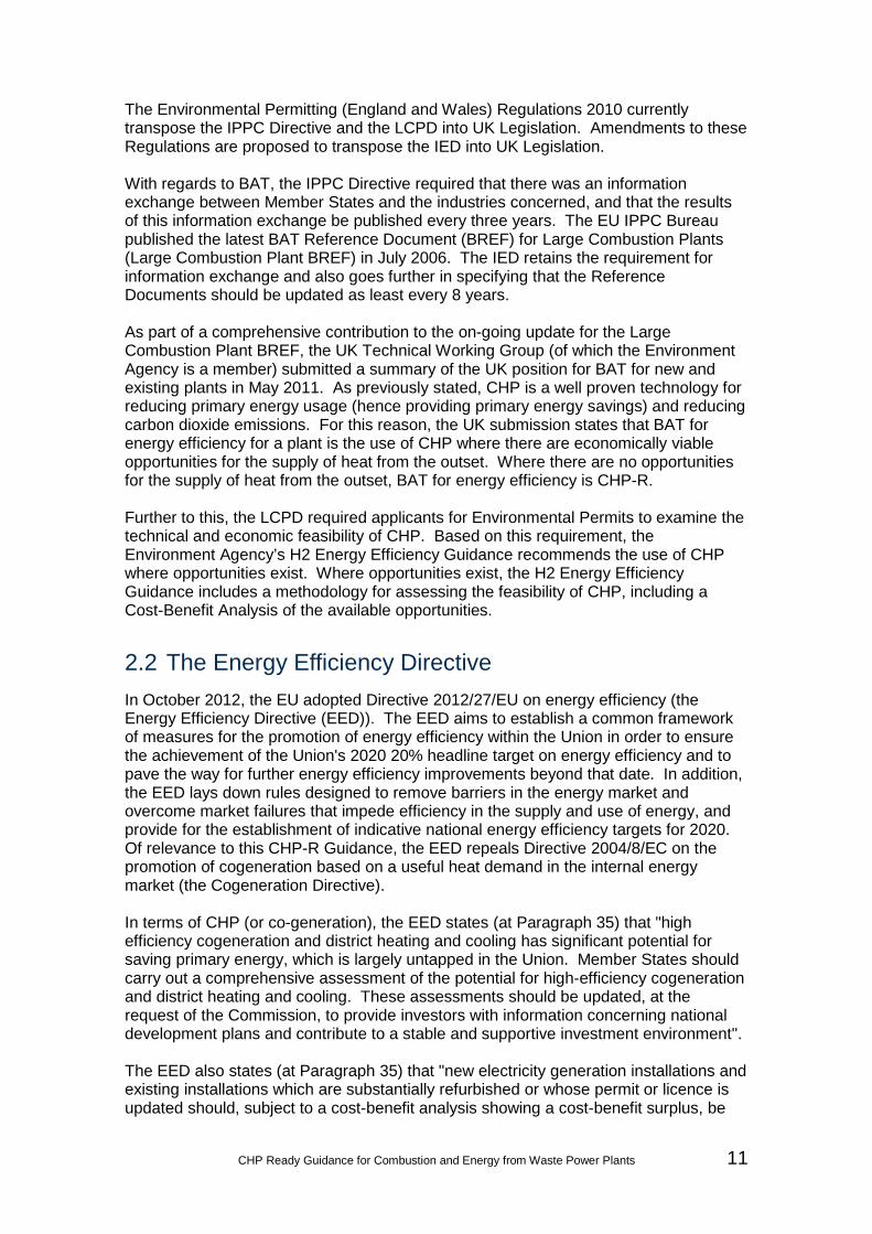
1.4 Factors Influencing Selection of Plant Location
This should include a description of the factors that have been used to select the location of the plant. The description should make reference to the following factors as appropriate:
• Likely potential for CHP opportunities*;
• Availability of sufficient land capacity;
• Current land use*;
• Compatibility with the policies of the relevant Local Plan(s) and the NPPF together with other relevant planning considerations;
• CHP provisions contained within the relevant Planning documents*;
• Environmental considerations (such as proximity to sensitive receptors including: Air Quality Management Areas (AQMAs); and Statutory Designated Sites (and the likely presence of Protected Species));
• Proximity of suitable connection point to the National Grid Electricity Transmission System, and available capacity for export to the Electricity Transmission System;
• Proximity to / availability of fuel source;
• Proximity to / availability of cooling water;
• Likely suitability for CCS (if applicable)*; and
• Any other relevant considerations.
* For the purposes of demonstrating CHP-R the items marked (*) must be included.

26 CHP Ready Guidance for Combustion and Energy from Waste Power Plants
1.5 Operation of Plant
a) Proposed Operational Plant Load %
This should clearly describe the proposed operating load point of the plant. For example:
• For gas turbine plant, this should comprise the number of gas turbines in operation and the load as % of gas turbine base load.
• For steam plant, this should comprise the main steam flow as a percentage of maximum turbine continuous rating (%TMCR).
b) Thermal Input at Proposed Operational Plant Load MW
The plant thermal input (based on the Lower Heating Value (LHV)) at proposed operational plant load. Identified from modelling.
c) Net Electrical Output at Proposed Operational Plant Load
MW
The plant net electrical output at proposed operational plant load. Identified from modelling.
d) Net Electrical Efficiency at Proposed Operational Plant Load
%
The plant net electrical efficiency at proposed operational plant load based on the LHV. Identified from modelling.
e) Maximum Plant Load % This is the maximum possible plant load. The value to be used is 100%.
f) Thermal Input at Maximum Plant Load MW
The plant thermal input (based on the LHV) at 100% plant load. Identified from modelling.
g) Net Electrical Output at Maximum Plant Load MW
The plant net electrical output at 100% plant load. Identified from modelling. This is represented by Point D on Insert 3.
h) Net Electrical Efficiency at Maximum Plant Load %
The plant net electrical efficiency at 100% plant load based on the LHV. Identified from modelling. This is represented by Point D on Insert 3.

CHP Ready Guidance for Combustion and Energy from Waste Power Plants 27
i) Minimum Stable Plant Load %
This is the minimum stable plant load. This will vary with type of plant, and may be governed by the combustion stability or capability to meet emissions limits at low plant loads.
j) Thermal Input at Minimum Stable Plant Load MW The plant thermal input (based on the
LHV) at minimum stable plant load.
k) Net Electrical Output at Minimum Stable Plant Load MW
The plant net electrical output at minimum stable plant load. Identified from modelling. This is represented by Point A on Insert 3.
l) Net Electrical Efficiency at Minimum Stable Plant Load %
The plant net electrical efficiency at minimum stable plant load based on the LHV. Identified from modelling. This is represented by Point A on Insert 3.
1.6 Identified Potential Heat Loads
This should include a description of the identified potential heat loads in the vicinity of the plant. A plan showing all identified potential heat loads in the vicinity should be provided. For each potential heat load the following information should be provided:
• Name of identified heat load / recipient;
• Size of heat load (MW)
• Location of identified heat load / recipient including distance from the plant(where the identified heat load / recipient is a District Heating Network, the primary service location(s) should be provided);
• Nature of use of potential heat load; and
• Typical export and return requirements of the potential heat load.

28 CHP Ready Guidance for Combustion and Energy from Waste Power Plants
1.7 Selected Heat Load(s)
a) Category (e.g. Industrial / District Heating)
Of the identified potential heat loads under Requirement 1.6, appropriate selection of heat loads should be undertaken in discussion with the Potential Heat Load Recipient / Environment Agency. It should be noted that the heat loads for assessment must be agreed with the Environment Agency If more than one heat load is taken forward, then an assessment should be undertaken for all selected heat loads.
b) Maximum Heat Load Extraction Required MW
Of the identified potential heat loads under Requirement 1.6, appropriate selection of heat loads should be undertaken in discussion with the Potential Heat Load Recipient / Environment Agency. It should be noted that the heat loads for assessment must be agreed with the Environment Agency If more than one heat load is taken forward, then an assessment should be undertaken for all selected heat loads. .
1.8 Export and Return Requirements of Heat Load
a) Description of Heat Load Extraction
To complete, based on potential heat load extraction for CHP (e.g. steam / hot water)
b) Description of Heat Load Profile
To complete, based on potential heat load profile (e.g. constant or intermittent / fixed or variable load)
c) Export Pressure bar a To complete, based on the requirements at the terminal point with the heat load customer.
d) Export Temperature °C To complete, based on the requirements at the terminal point with the heat load customer.
e) Export Flow t/h To complete, based on the requirements at the terminal point with the heat load customer.
f) Return Pressure bar a To complete, if applicable, based on the requirements at the terminal point with the heat load customer.

CHP Ready Guidance for Combustion and Energy from Waste Power Plants 29
g) Return Temperature °C To complete, if applicable, based on the requirements at the terminal point with the heat load customer.
h) Return Flow t/h
To complete, if applicable, based on the requirements at the terminal point with the heat load customer.
Requirement 2: Identification of CHP Envelope
2.0 Comparative Efficiency of a Standalone Boiler for supplying the Heat Load
90 % LHV
This is used only to calculate the primary energy savings (or reduction in primary energy usage) as a comparative guide.
2.1 Heat Extraction at 100% Plant Load
a) Maximum Heat Load Extraction at 100% Plant Load
MW
This is the maximum possible heat load extraction within the technical limitations of the plant at 100% plant load (i.e. heat load extraction beyond which major plant modification would be required). This will vary with type of plant. This is represented by Point C on Insert 3.
b) Maximum Heat Extraction Export Flow at 100% Plant Load
t/h
This should be consistent with the:
• Steam conditions given in 1.8; and
• The figure given in 2.1(a).
c) CHP Mode Net Electrical Output at 100% Plant Load MW
The plant with CHP net electrical output at 100% plant load. Identified from modelling. This is represented by Point C on Insert 3.
d) CHP Mode Net Electrical Efficiency at 100% Plant Load
%
The plant with CHP net electrical efficiency at 100% plant load based on the LHV. Identified from modelling. This is represented by Point C on Insert 3.
e) CHP Mode Net CHP Efficiency at 100% Plant Load
%
The plant with CHP net CHP efficiency at 100% plant load based on the LHV. Identified from modelling. This is represented by Point C on Insert 3.

30 CHP Ready Guidance for Combustion and Energy from Waste Power Plants
f) Reduction in Primary Energy Usage for CHP Mode at 100% Plant Load
%
The reduction in primary energy usage (i.e. measure of primary energy savings) is based on the EED and is given by:
⎣⎢⎢⎡1 −
1𝐶𝐻𝑃 𝐻𝜂𝑅𝑒𝑓 𝐻𝜂
+𝐶𝐻𝑃 𝐸𝜂𝑅𝑒𝑓 𝐸𝜂 ⎦
⎥⎥⎤∙ 100
Or (with reference to the values calculated in this CHP-R Assessment) this can also be given by:
�1 −1
𝐶𝐻𝑃𝜂𝐻 + 𝐸 �
𝐻𝑅𝑒𝑓 𝐻𝑛
+ 𝐸𝑅𝑒𝑓 𝐸𝑛
�� ∙ 100
Where: CHP Hη : CHP Heat Efficiency CHP Eη : CHP Electrical Efficiency CHPη : CHP Efficiency Ref Hη : Reference Heat Efficiency15 Ref Eη : Reference Electrical Efficiency16 H : Heat Load Extraction E : CHP Mode Net Electrical Output
2.2 Heat Extraction at Minimum Stable Plant Load
a) Maximum Heat Load Extraction at Minimum Stable Plant Load
MW
This is the maximum possible heat load extraction within the technical limitations of the plant at minimum stable plant load (i.e. heat load extraction beyond which major plant modification would be required). This will vary with type of plant. This is represented by Point B on Insert 3.
b) Maximum Heat Extraction Export Flow at Minimum Stable Plant Load
t/h
This should be consistent with the:
• Steam conditions given in 1.8; and
• The figure given in 2.2(a).
15 This is the Comparative Efficiency of a Standalone Boiler for supplying the Heat Load [2.0]. 16 This is the power plant net electrical efficiency without heat extraction.

CHP Ready Guidance for Combustion and Energy from Waste Power Plants 31
c) CHP Mode Net Electrical Output at Minimum Stable Plant Load
MW
The plant with CHP net electrical output at minimum stable plant load. Identified from modelling. This is represented by Point B on Insert 3.
d) CHP Mode Net Electrical Efficiency at Minimum Stable Plant Load
%
The plant with CHP net electrical efficiency at minimum stable plant load based on the LHV. Identified from modelling. This is represented by Point B on Insert 3.
e) CHP Mode Net CHP Efficiency at Minimum Stable Plant Load
%
The plant with CHP net CHP efficiency at minimum stable plant load based on the LHV. Identified from modelling. This is represented by Point B on Insert 3.
f) Reduction in Primary Energy Usage for CHP Mode at Minimum Stable Plant Load
%
The reduction in primary energy usage (i.e. measure of primary energy savings) is based on the EED. This is given by 2.1(f).
2.3
Can the Plant supply the Selected Identified Potential Heat Load (i.e. is the Identified Potential Heat Load within the ‘CHP Envelope’)?
Should be identified: Yes or No
Requirement 3: Operation of the Plant with the Selected Identified Heat Load
3.1 Proposed Operation of Plant with CHP
a) CHP Mode Net Electrical Output at Proposed Operational Plant Load
MW
The plant with CHP net electrical output at proposed operational plant load. Identified from modelling. This is represented by Point E on Insert 3.
b) CHP Mode Net Electrical Efficiency at Proposed Operational Plant Load
%
The plant with CHP net electrical efficiency at proposed operational plant load based on the LHV. Identified from modelling. This is represented by Point E on Insert 3.

32 CHP Ready Guidance for Combustion and Energy from Waste Power Plants
c) CHP Mode Net CHP Efficiency at Proposed Operational Plant Load
%
The plant with CHP net CHP efficiency at proposed operational plant load based on the LHV. Identified from modelling. This is represented by Point E on Insert 3.
d)
Reduction in Net Electrical Output for CHP Mode at Proposed Operational Plant Load
MW
The extraction of heat from the plant will cause a corresponding loss in electrical power. Typically, the higher the quality of the extracted heat, the greater the corresponding loss in electrical power. The reduction in electrical power output due to the heat load extraction at proposed operational plant load is given by: (Net Electrical Output at Proposed Operational Plant Load) – (CHP Mode Net Electrical Output at Proposed Operational Plant Load).
e)
Reduction in Net Electrical Efficiency for CHP Mode at Proposed Operational Plant Load
%
The reduction in net electrical efficiency (based on the LHV due to the heat load extraction at proposed operational plant load is given by: (Net Electrical Efficiency at Proposed Operational Plant Load) – (CHP Mode Net Electrical Efficiency at Proposed Operational Plant Load).
f)
Reduction in Primary Energy Usage for CHP Mode at Proposed Operational Plant Load
%
The reduction in primary energy usage (i.e. measure of primary energy savings) is based on the EED. This is given by 2.1(f).
g) Z Ratio
The Z-Ratio compares the heat exported to the reduction in electrical power. A higher Z-Ratio indicates a more efficient method of heat supply. This is given by: (Maximum Heat Load Extraction Required) / (Reduction in Net Electrical Output for CHP Mode at Proposed Operational Plant Load)

CHP Ready Guidance for Combustion and Energy from Waste Power Plants 33
Requirement 4: Technical Provisions and Space Requirements
4.1 Description of Likely Suitable Extraction Points
Demonstration of CHP-R does not require that suitable extraction points are fitted from the outset, but rather it is technically feasible to retrofit at a later date. Therefore, based on the likely heat load, a suitable method (or suitable methods) of extraction should be identified, along with the associated technical requirements of such extraction. For example, for heat load extraction from a CCGT power plant for a District Heating Scheme, a quantity of low pressure steam would be required. A suitable method of extraction would involve extracting a quantity of low pressure steam from the Intermediate Pressure / Low Pressure Turbine Crossover (if present). If this is not possible, but steam can be extracted from the Cold Reheat Pipe, a suitable method of extraction would involve extracting the steam and passing it through a let-down station or back pressure steam turbine. Additional information is presented in Appendix D.
4.2
Description of Potential Options which could be incorporated in the Plant, should a CHP Opportunity be realised outside the 'CHP Envelope'
If heat load extraction in sufficient quantities is not possible, consideration should be given to potential options which could be incorporated into the plant should the realised CHP opportunity be outside the identified ‘CHP Envelope’. For example:
• Back-up boilers operated by the plant operator / head load recipient; and
• The use of heat storage equipment.
4.3
Description of how the future Costs and Burdens associated with supplying the Identified Heat Load / Potential CHP Opportunity have been minimised through the implementation of an appropriate CHP-R design
A description of how the future costs and burdens of CHP have been minimised. This may include discussions with major plant or component manufactures to investigate modifications to design which could allow for the maximum heat supply without compromising the initial performance, flexibility and reliability of the plant.

34 CHP Ready Guidance for Combustion and Energy from Waste Power Plants
4.4
Provision of Site Layout of the Plant, indicating Available Space which could be made available for CHP-R
Following identification of suitable extraction points and potential options which could be incorporated into the design of the plant should a CHP opportunity be realised outside the ‘CHP Envelope’, demonstration of CHP-R comprises indication of the available space for the extraction points / potential options. For example:
• When operating within the ‘CHP Envelope’, in addition to the extraction points, there may be a need for space to be provided for:
- Supply and return pipes within the plant site, for steam and / or hot water;
- The Water Treatment Plant / Demineralisation Plant, which may need to be increased in size if steam is to be piped off-site without condensate return;
- A let-down station or back pressure steam turbine; and,
- Back-up boilers, which could supply heat in the event that the plant is off-line.
• When operating outside the ‘CHP Envelope’, there may be a need for space to be provided for:
- Back-up boilers; and
- Heat storage equipment.
It is noted that the available space for the provision of additional balance of plant systems / control and instrumentation systems should be in the most suitable location, and therefore may not always be on the plant site itself.

CHP Ready Guidance for Combustion and Energy from Waste Power Plants 35
Requirement 5: Integration of CHP and Carbon Capture
5.1 Is the Plant required to be CCR? Should be identified: Yes or No
5.2 Export and Return Requirements Identified for Carbon Capture
100% Plant Load
a) Heat Load Extraction for Carbon Capture at 100% Plant Load
MW
This is the heat load extraction required for carbon capture at 100% Plant Load. This does not include the heat available for export.
b) Description of Heat Export (e.g. Steam / Hot Water)
To complete, based on the likely heat load extraction for carbon capture at 100% Plant Load.
c) Export Pressure bar a
To complete, based on the likely requirements at the terminal point with the Carbon Capture Plant at 100% Plant Load.
d) Export Temperature °C
To complete, based on the likely requirements at the terminal point with the Carbon Capture Plant at 100% Plant Load.
e) Export Flow t/h
To complete, based on the likely requirements at the terminal point with the Carbon Capture Plant at 100% Plant Load.
f) Return Pressure bar a
To complete, based on the likely requirements at the terminal point with the Carbon Capture Plant at 100% Plant Load.
g) Return Temperature °C
To complete, based on the likely requirements at the terminal point with the Carbon Capture Plant at 100% Plant Load.
h) Return Flow t/h
To complete, based on the likely requirements at the terminal point with the Carbon Capture Plant at 100% Plant Load.
i) Likely Suitable Extraction Points
Based on the likely heat load extraction for carbon capture a suitable method (or suitable methods) of extraction should be identified.
Minimum Stable Plant Load
j) Heat Load Extraction for Carbon Capture at Minimum Stable Plant Load
MW
This is the heat load extraction required for carbon capture at Minimum Stable Plant Load. This does not include the heat available for export.

36 CHP Ready Guidance for Combustion and Energy from Waste Power Plants
k) Description of Heat Export (e.g. Steam / Hot Water)
To complete, based on the likely heat load extraction for carbon capture at Minimum Stable Plant Load.
l) Export Pressure bar a
To complete, based on the likely requirements at the terminal point with the Carbon Capture Plant at Minimum Stable Plant Load.
m) Export Temperature °C
To complete, based on the likely requirements at the terminal point with the Carbon Capture Plant at Minimum Stable Plant Load.
n) Export Flow t/h
To complete, based on the likely requirements at the terminal point with the Carbon Capture Plant at Minimum Stable Plant Load.
o) Return Pressure bar a
To complete, based on the likely requirements at the terminal point with the Carbon Capture Plant at Minimum Stable Plant Load.
p) Return Temperature °C
To complete, based on the likely requirements at the terminal point with the Carbon Capture Plant at Minimum Stable Plant Load.
q) Return Flow t/h
To complete, based on the likely requirements at the terminal point with the Carbon Capture Plant at Minimum Stable Plant Load.
r) Likely Suitable Extraction Points
Based on the likely heat load extraction for carbon capture, a suitable method (or suitable methods) of extraction should be identified.
5.3 Operation of Plant with Carbon Capture (without CHP)
a) Maximum Plant Load with Carbon Capture %
This is the maximum possible plant load with carbon capture. The value to be used is 100%.
b) Carbon Capture Mode Thermal Input at Maximum Plant Load
MW
The plant with carbon capture thermal input (based on the LHV) at 100% plant load. Identified from modelling.
c) Carbon Capture Mode Net Electrical Output at Maximum Plant Load
MW
The plant with carbon capture net electrical output at 100% plant load. Identified from modelling.
d) Carbon Capture Mode Net Electrical Efficiency at Maximum Plant Load
%
The plant with carbon capture net electrical efficiency at 100% plant load based on the LHV. Identified from modelling.

CHP Ready Guidance for Combustion and Energy from Waste Power Plants 37
e) Minimum Stable Plant Load with CCS %
This is the minimum stable plant load with carbon capture. This will vary with type of plant.
f) Carbon Capture Mode CCS Thermal Input at Minimum Stable Plant Load
MW The plant with carbon capture thermal input (based on the LHV) at minimum stable plant load.
g) Carbon Capture Mode Net Electrical Output at Minimum Stable Plant Load
MW
The plant with carbon capture net electrical output at minimum stable plant load. Identified from modelling.
h) Carbon Capture Mode Net Electrical Efficiency at Minimum Stable Plant Load
%
The plant with carbon capture net electrical efficiency at minimum stable plant load based on the LHV. Identified from modelling.
5.4 Heat Extraction for CHP at 100% Plant Load with Carbon Capture
a)
Maximum Heat Load Extraction at 100% Plant Load with Carbon Capture [H]
MW
This is the maximum possible heat load extraction within the technical limitations of the plant with carbon capture at 100% plant load (i.e. heat load extraction beyond which major plant modification would be required). This will vary with type of plant, and Carbon Capture Plant requirement.
b) Maximum Heat Extraction Export Flow at 100% Plant Load with Carbon Capture
t/h
This should be consistent with the:
• Steam conditions given in 1.8; and
• The figure given in 5.4(a).
c) Carbon Capture and CHP Mode Net Electrical Output at 100% Plant Load
MW
The plant with carbon capture and CHP net electrical output at 100% plant load. Identified from modelling.
d)
Carbon Capture and CHP Mode Net Electrical Efficiency at 100% Plant Load
%
The plant with carbon capture and CHP net electrical efficiency at 100% plant load based on the LHV. Identified from modelling.
e) Carbon Capture and CHP Mode Net CHP Efficiency at 100% Plant Load
%
The plant with carbon capture and CHP net CHP efficiency at 100% plant load based on the LHV. Identified from modelling.
f)
Reduction in Primary Energy Usage for Carbon Capture and CHP Mode at 100% Plant Load
%
The reduction in primary energy usage (i.e. measure of primary energy savings) is based on the EED. This is given by 2.1(f).

38 CHP Ready Guidance for Combustion and Energy from Waste Power Plants
5.5 Heat Extraction at Minimum Stable Plant Load with Carbon Capture
a)
Maximum Heat Load Extraction at Minimum Stable Plant Load with Carbon Capture
MW
This is the maximum possible heat load extraction within the technical limitations of the plant with carbon capture at minimum stable plant load (i.e. heat load extraction beyond which major plant modification would be required). This will vary with type of plant, and Carbon Capture Plant requirement.
b)
Maximum Heat Extraction Export Flow at Minimum Stable Plant Load with Carbon Capture
t/h
This should be consistent with the: • Steam conditions given in 1.8;
and
• The limit given in 5.5(a).
c)
Carbon Capture and CHP Mode Net Electrical Output at Minimum Stable Plant Load
MW
The plant with carbon capture and CHP net electrical output at minimum stable plant load. Identified from modelling.
d)
Carbon Capture and CHP Mode Net Electrical Efficiency at Minimum Stable Plant Load
%
The plant with carbon capture and CHP net electrical efficiency at minimum stable plant load based on the LHV. Identified from modelling.
e) Carbon Capture and CHP Mode Net CHP Efficiency at Minimum Stable Plant Load
%
The plant with carbon capture and CHP net CHP efficiency at minimum stable plant load based on the LHV. Identified from modelling.
f)
Reduction in Primary Energy Usage for Carbon Capture and CHP Mode at Minimum Stable Plant Load
%
The reduction in primary energy usage (i.e. measure of primary energy savings) is based on the EED. This is given by 2.1(f).
5.6
Can the Plant with Carbon Capture supply the Selected Identified Potential Heat Load (i.e. is the Identified Potential Heat Load within the ‘CHP and Carbon Capture Envelope’)?
Should be identified: Yes or No

CHP Ready Guidance for Combustion and Energy from Waste Power Plants 39
5.7
Description of Potential Options which could be incorporated in the Plant for useful integration of any realised CHP System and Carbon Capture System
The Carbon Capture Plant will reject large quantities of heat. A description of potential uses of this heat should be provided with regard to how it could be used in any CHP System. If this is not possible, consideration should be given to potential options which could be incorporated into the plant with carbon capture should the realised CHP opportunity be outside the identified ‘CHP and Carbon Capture Envelope’.
Requirement 6: Economics of CHP-R
6.1 Economic Assessment of CHP-R
A clear summary of the high level economic assessment (or Cost-Benefit Analysis) should be provided, stating for the selected potential future opportunity for heat supply, the associated potential future revenues / benefits and likely additional initial costs for the plant to be CHP-R. Unless it can be demonstrated that the additional initial costs for the plant to be CHP-R would be excessive (and outweigh the associated potential future revenues / benefits), it is considered that the economic viability of CHP-R is demonstrated.
BAT Assessment
Is the new plant a CHP plant at the outset (i.e. are there economically viable CHP opportunities at the outset)?
Should be identified: Yes or No. If yes, then the new plant is considered BAT.
If not, is the new plant a CHP-R plant at the outset?
Should be identified: Yes or No If no, applicants should provide evidence as to why their plant should be excluded from being CHP-R.
Once the new plant is CHP-R, is it BAT?
Should be identified: Yes or No (as a result of periodic reviews of opportunities for heat supply once the CHP-R plant becomes operational).

40 CHP Ready Guidance for Combustion and Energy from Waste Power Plants
Appendix B: Case Studies / Worked Examples This Appendix provides a number of Case Studies / Worked Examples using the CHP-R Assessment Form. The Case Studies / Worked Examples are summarised below:
Description
Case Study 1 Case Study 1 is based on a large multi-shaft CCGT power plant, which incorporates an IP / LP crossover pipe. Two selected heat loads are considered simultaneously. These are a heat load associated with an industrial use, and a heat load associated with district heating.
Case Study 2 Case Study 2 is based on a large multi-shaft CCGT power plant, which incorporates an IP / LP crossover pipe. One selected heat load is considered, which is associated with an industrial use.
Case Study 3 Case Study 3 is based on a biomass plant. One selected heat load is considered, which is associated with district heating.
Case Study 4 Case Study 4 is based on an EfW plant. One selected heat load is considered, which is associated with district heating.
Case Study 5a Case Study 5a is based on a small single-shaft CCGT power plant, which does not incorporate an IP / LP crossover pipe. One selected heat load is considered, which is associated with district heating. Within Case Study 5a, although the selected heat load lies inside the CHP Envelope, the steam cannot be extracted from the IP turbine exhaust. Therefore, the steam is extracted from the cold reheat pipe, passed through a let-down station and supplied to the District Heating System.
Case Study 5b Case Study 5b provides further assessment of Case Study 5a. Accordingly, Case Study 5b is also based on a small single shaft CCGT power plant, which does not incorporate an IP / LP crossover pipe. One selected heat load is considered, which is associated with district heating. Similar to Case Study 5a, although the selected heat load lies inside the CHP Envelope, the steam cannot be extracted from the IP turbine exhaust. Therefore, the steam is extracted from the cold reheat pipe, passed through a back pressure steam turbine and supplied to the District Heating System.

CHP Ready Guidance for Combustion and Energy from Waste Power Plants 41
Case Study / Worked Example 1 #
Description
Units
Notes / Instructions
Requirement 1: Plant, Plant Location and Potential Heat Loads 1.1 Plant Name Case Study 1
1.2 Plant Description
Plant comprises:
• Multi-shaft (1 + 1) Configuration;
• IP / LP crossover pipe available as an extraction point;
• Hybrid Cooling; and
• UK ambient conditions.
1.3 Plant Location (Postcode / GridRef) Not required for the Case Study
1.4 Factors Influencing Selection of Plant Location Not required for the Case Study
1.5 Operation of Plant
a) Proposed Operational Plant Load % 100
b) Thermal Input at Proposed Operational Plant Load MW 764.5
c) Net Electrical Output at Proposed Operational Plant Load
MW 434.1
d) Net Electrical Efficiency at Proposed Operational Plant Load
% 56.8
e) Maximum Plant Load % 100
f) Thermal Input at Maximum Plant Load MW 764.5
g) Net Electrical Output at Maximum Plant Load MW 434.1
h) Net Electrical Efficiency at Maximum Plant Load % 56.8
i) Minimum Stable Plant Load % 40
j) Thermal Input at Minimum Stable Plant Load MW 432.1
k) Net Electrical Output at Minimum Stable Plant Load MW 212.4
l) Net Electrical Efficiency at Minimum Stable Plant Load % 49.2
1.6 Identified Potential Heat Loads
30 MW of District Heating and 30 MW of Industrial Steam
1.7 Selected Heat Load(s)

42 CHP Ready Guidance for Combustion and Energy from Waste Power Plants
a) Category (e.g. Industrial / District Heating) District Heating (DH) / Industrial (I)
b) Maximum Heat Load Extraction Required MW 60
1.8 Export and Return Requirements of Heat Load
a) Description of Heat Load Extraction Hot water (DH) / Superheated steam (I)
b) Description of Heat Load Profile Constant
c) Export Pressure bar a 5 (DH) / 20 (I) d) Export Temperature °C 95 (DH) / 300 (I) e) Export Flow t/h 645 (DH) / 40 (I) f) Return Pressure bar a 3 (DH) / 5 (I) g) Return Temperature °C 55 (DH) / 82.2 (I)
h) Return Flow t/h 645 (DH) / 36 (I) (Note: Only 90% of the industrial steam is returned)
Requirement 2: Identification of CHP Envelope
2.0 Comparative Efficiency of a Standalone Boiler for supplying the Heat Load
90 % LHV 90
2.1 Heat Extraction at 100% Plant Load
a) Maximum Heat Load Extraction at 100% Plant Load
MW 161 (42.5 (DH) / 118.5 (I))
b) Maximum Heat Extraction Export Flow at 100% Plant Load
t/h 910 (DH) / 157 (I)
c) CHP Mode Net Electrical Output at 100% Plant Load MW 389
d) CHP Mode Net Electrical Efficiency at 100% Plant Load
% 51.0
e) CHP Mode Net CHP Efficiency at 100% Plant Load
% 72.0
f) Reduction in Primary Energy Usage for CHP Mode at 100% Plant Load
% 11.6
2.2 Heat Extraction at Minimum Stable Plant Load
a) Maximum Heat Load Extraction at Minimum Stable Plant Load
MW 106
b) Heat Extraction Export Flow at Minimum Stable Plant Load
t/h 620 (DH) / 102 (I)

CHP Ready Guidance for Combustion and Energy from Waste Power Plants 43
c) CHP Mode Net Electrical Output at Minimum Stable Plant Load
MW 182
d) CHP Mode Net Electrical Efficiency at Minimum Stable Plant Load
% 42.0
e) CHP Mode Net CHP Efficiency at Minimum Stable Plant Load
% 66.5
f) Reduction in Primary Energy Usage for CHP Mode at Minimum Stable Plant Load
% 11.2
2.3
Can the Plant supply the Selected Identified Potential Heat Load (i.e. is the Identified Potential Heat Load within the ‘CHP Envelope’)?
Yes
Requirement 3: Operation of the Plant with the Selected Identified Heat Load
3.1 Proposed Operation of Plant with CHP
a) CHP Mode Net Electrical Output at Proposed Operational Plant Load
MW 419
b) CHP Mode Net Electrical Efficiency at Proposed Operational Plant Load
% 54.8
c) CHP Mode Net CHP Efficiency at Proposed Operational Plant Load
% 62.7
d)
Reduction in Net Electrical Output for CHP Mode at Proposed Operational Plant Load
MW 15.1
e)
Reduction in Net Electrical Efficiency for CHP Mode at Proposed Operational Plant Load
% 3.5
f)
Reduction in Primary Energy Usage for CHP Mode at Proposed Operational Plant Load
% 5.0
g) Z Ratio 4.0 Requirement 4: Technical Provisions and Space Requirements

44 CHP Ready Guidance for Combustion and Energy from Waste Power Plants
4.1 Description of Likely Suitable Extraction Points
Steam for the District Heating System is extracted from the Low Pressure (LP) cross over pipe, (which supplies steam to the LP turbine from the exhaust of the Intermediate Pressure (IP) turbine). Steam for the Industrial Process is extracted from the cold reheat line. To facilitate this, a cold reheat header would be required.
4.2
Description of Potential Options which could be incorporated in the Plant, should a CHP Opportunity be realised outside the 'CHP Envelope'
N / A (CHP opportunity lies within the CHP Envelope)
4.3
Description of how the future Costs and Burdens associated with supplying the Identified Heat Load / Potential CHP Opportunity have been minimised through the implementation of an appropriate CHP-R design
Not required for the Case Study
4.4
Provision of Site Layout of the Plant, indicating Available Space which could be made available for CHP-R
Please see Layout CS 01. The District Heating System will (likely) include: extraction piping; control and shut-off valves, and actuators; a Pressure Reduction and De-superheating Station; District Heaters; District Heating supply and return lines; condensate return piping (to the condensate header); interconnecting piping; drains; pipe bridges / supports; and Control and Instrumentation / electrical connections. The Industrial Process will (likely) include: the installation of a cold reheat header; extraction piping; control and shut-off valves, and actuators; a Pressure Reduction and De-Superheating Station; condensate return piping; interconnecting pipeline; drains pipe bridges / supports; and Control and Instrumentation / electrical connections. A Stand-by Boiler is also included. Provision is also made for possible extension of the Water Treatment Plant.
Requirement 5: Integration of CHP and Carbon Capture

CHP Ready Guidance for Combustion and Energy from Waste Power Plants 45
5.1 Is the Plant required to be CCR? Yes
5.2 Export and Return Requirements Identified for Carbon Capture
100% Plant Load
a) Heat Load Extraction for Carbon Capture at 100% Plant Load
MW 128.9
b) Description of Heat Export (e.g. Steam / Hot Water) Low pressure steam
c) Export Pressure bar a 3.4 d) Export Temperature °C 150 e) Export Flow t/h 212.8 f) Return Pressure bar a 3.4 g) Return Temperature °C 137.4 h) Return Flow t/h 212.8
i) Likely Suitable Extraction Points LP superheated steam / HP water
desuperheating Minimum Stable Plant Load
j) Heat Load Extraction for Carbon Capture at Minimum Stable Plant Load
MW 71.5
k) Description of Heat Export (e.g. Steam / Hot Water) Low pressure steam
l) Export Pressure bar a 2.7 m) Export Temperature °C 150 n) Export Flow t/h 116 o) Return Pressure bar a 2.7 p) Return Temperature °C 130 q) Return Flow t/h 116
r) Likely Suitable Extraction Points LP superheated steam / HP water
desuperheating
5.3 Operation of Plant with Carbon Capture (without CHP)
a) Maximum Plant Load with Carbon Capture % 100
b) Carbon Capture Mode Thermal Input at Maximum Plant Load
MW 764.7
c) Carbon Capture Mode Net Electrical Output at Maximum Plant Load
MW 400.4
d) Carbon Capture Mode Net Electrical Efficiency at Maximum Plant Load
% 52.4
e) Minimum Stable Plant Load with CCS % 40
f) Carbon Capture Mode CCS Thermal Input at Minimum Stable Plant Load
MW 432

46 CHP Ready Guidance for Combustion and Energy from Waste Power Plants
g) Carbon Capture Mode Net Electrical Output at Minimum Stable Plant Load
MW 192
h) Carbon Capture Mode Net Electrical Efficiency at Minimum Stable Plant Load
% 44.5
5.4 Heat Extraction for CHP at 100% Plant Load with Carbon Capture
a)
Maximum Heat Load Extraction at 100% Plant Load with Carbon Capture [H]
MW 35
b) Maximum Heat Extraction Export Flow at 100% Plant Load with Carbon Capture
t/h 185 (DH) / 35 (I)
c) Carbon Capture and CHP Mode Net Electrical Output at 100% Plant Load
MW 389.2
d)
Carbon Capture and CHP Mode Net Electrical Efficiency at 100% Plant Load
% 50.9
e) Carbon Capture and CHP Mode Net CHP Efficiency at 100% Plant Load
% 55.4
f)
Reduction in Primary Energy Usage for Carbon Capture and CHP Mode at 100% Plant Load
% 2.0
5.5 Heat Extraction at Minimum Stable Plant Load with Carbon Capture
a)
Maximum Heat Load Extraction at Minimum Stable Plant Load with Carbon Capture
MW 36
b)
Maximum Heat Extraction Export Flow at Minimum Stable Plant Load with Carbon Capture
t/h 191 (DH) / 36 (I)
c)
Carbon Capture and CHP Mode Net Electrical Output at Minimum Stable Plant Load
MW 180.1
d)
Carbon Capture and CHP Mode Net Electrical Efficiency at Minimum Stable Plant Load
% 41.7
e) Carbon Capture and CHP Mode Net CHP Efficiency at Minimum Stable Plant Load
% 50.1
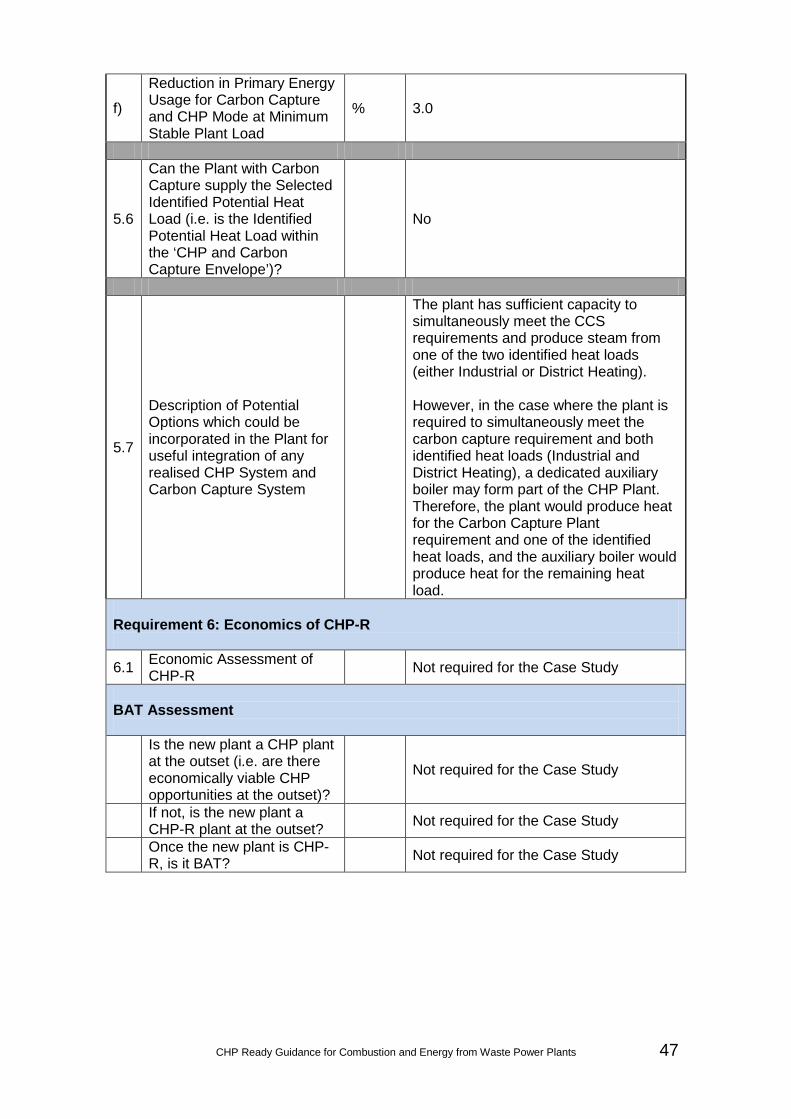
CHP Ready Guidance for Combustion and Energy from Waste Power Plants 47
f)
Reduction in Primary Energy Usage for Carbon Capture and CHP Mode at Minimum Stable Plant Load
% 3.0
5.6
Can the Plant with Carbon Capture supply the Selected Identified Potential Heat Load (i.e. is the Identified Potential Heat Load within the ‘CHP and Carbon Capture Envelope’)?
No
5.7
Description of Potential Options which could be incorporated in the Plant for useful integration of any realised CHP System and Carbon Capture System
The plant has sufficient capacity to simultaneously meet the CCS requirements and produce steam from one of the two identified heat loads (either Industrial or District Heating). However, in the case where the plant is required to simultaneously meet the carbon capture requirement and both identified heat loads (Industrial and District Heating), a dedicated auxiliary boiler may form part of the CHP Plant. Therefore, the plant would produce heat for the Carbon Capture Plant requirement and one of the identified heat loads, and the auxiliary boiler would produce heat for the remaining heat load.
Requirement 6: Economics of CHP-R
6.1 Economic Assessment of CHP-R Not required for the Case Study
BAT Assessment
Is the new plant a CHP plant at the outset (i.e. are there economically viable CHP opportunities at the outset)?
Not required for the Case Study
If not, is the new plant a CHP-R plant at the outset? Not required for the Case Study
Once the new plant is CHP-R, is it BAT? Not required for the Case Study

48 CHP Ready Guidance for Combustion and Energy from Waste Power Plants
CHP Envelope for Case Study 1
CHP and Carbon Capture Envelope for Case Study 1
0
50,000
100,000
150,000
200,000
250,000
300,000
350,000
400,000
450,000
500,000
0 20,000 40,000 60,000 80,000 100,000 120,000 140,000 160,000 180,000
Elec
tric
al P
ower
Out
put
(kW
)
Heat Load (kW)
MSL 60% Plant Load 80% Plant Load 100% Plant Load Operating Conditions
ACHPη = 49.2%PES = 0%
DCHPη = 56.8%PES = 0%
BCHPη = 66.5%PES = 11.2%
CCHPη = 72.0%PES = 11.6%
ECHPη = 62.7%PES = 5.0%
0
50,000
100,000
150,000
200,000
250,000
300,000
350,000
400,000
450,000
0 5,000 10,000 15,000 20,000 25,000 30,000 35,000 40,000
Elec
tric
al P
ower
Out
put
(kW
)
Heat Load (kW)
MSL 60% Plant Load 80% Plant Load 100% Plant Load Operating Conditions
ACHPη = 44.5%PES = 0%
DCHPη = 52.4%PES = 0%
BCHPη = 50.1%PES = 3.0%
CCHPη = 55.4%PES = 2.0%
EProposed Operating Conditions are outside CHP Envelope

Date:
Scale:
Sheet:
Designed:
Draw
n:
Approved:
Checked:
© C
opyright Parsons B
rinckerhoffTel:
44-(0)191-226-2000Fax:
44-(0)191-226-2104
A3
Am
ber Court
William
Arm
strong Drive
New
castle upon Tyne NE
4 7YQ
30/07/2012
Plot Date: 09/08/2012 11:40:02 K:\Projects\3511829A - CHP-R Case Study\Z. Drawings\1. Current\Civil\CS1 mod.dwgFile Name:
Minikin, SandraLogin:
Title:C
lient:
Project:
Notes:
App
Chk
By
Description
Date
Rev
Project N
umber:
Revision:
Draw
ing Num
ber:
Project Number: Revision:Drawing Number:
ALM
EB
1:1000S
ITE LA
YO
UT PLAN
FOR
CA
SE
STU
DY 1
CC
GT PO
WE
R PLAN
T WITH
30MW
DIS
TRIC
T HEATIN
G &
EN
VIR
ON
ME
NT AG
ENC
Y
CH
P-R
GU
IDA
NC
E3511829A
CS 01
3511829A CS 01
30MW
IND
USTR
IAL CH
P U
SE

50 CHP Ready Guidance for Combustion and Energy from Waste Power Plants
Case Study / Worked Example 2 #
Description
Units
Notes / Instructions
Requirement 1: Plant, Plant Location and Potential Heat Loads 1.1 Plant Name Case Study 2
1.2 Plant Description
Plant comprises:
• Multi-shaft (2 + 1) Configuration;
• IP / LP crossover pipe available as an extraction point;
• Hybrid Cooling; and
• UK ambient conditions.
1.3 Plant Location (Postcode / GridRef) Not required for the Case Study
1.4 Factors Influencing Selection of Plant Location Not required for the Case Study
1.5 Operation of Plant
a) Proposed Operational Plant Load % 100
b) Thermal Input at Proposed Operational Plant Load MW 1543
c) Net Electrical Output at Proposed Operational Plant Load
MW 889
d) Net Electrical Efficiency at Proposed Operational Plant Load
% 57.6
e) Maximum Plant Load % 100
f) Thermal Input at Maximum Plant Load MW 1543
g) Net Electrical Output at Maximum Plant Load MW 889
h) Net Electrical Efficiency at Maximum Plant Load % 57.6
i) Minimum Stable Plant Load % 40
j) Thermal Input at Minimum Stable Plant Load MW 854.6
k) Net Electrical Output at Minimum Stable Plant Load MW 429
l) Net Electrical Efficiency at Minimum Stable Plant Load % 50.2
1.6 Identified Potential Heat Loads
200 MW Industrial 1.7 Selected Heat Load(s)

CHP Ready Guidance for Combustion and Energy from Waste Power Plants 51
a) Category (e.g. Industrial / District Heating) Industrial
b) Maximum Heat Load Extraction Required MW 200
1.8 Export and Return Requirements of Heat Load
a) Description of Heat Load Extraction Superheated steam
b) Description of Heat Load Profile Constant
c) Export Pressure bar a 20 d) Export Temperature °C 300 e) Export Flow t/h 273 f) Return Pressure bar a 5 g) Return Temperature °C 82.2 h) Return Flow t/h 273 Requirement 2: Identification of CHP Envelope
2.0 Comparative Efficiency of a Standalone Boiler for supplying the Heat Load
90 % LHV 90
2.1 Heat Extraction at 100% Plant Load
a) Maximum Heat Load Extraction at 100% Plant Load
MW 251
b) Maximum Heat Extraction Export Flow at 100% Plant Load
t/h 337
c) CHP Mode Net Electrical Output at 100% Plant Load MW 807
d) CHP Mode Net Electrical Efficiency at 100% Plant Load
% 52.3
e) CHP Mode Net CHP Efficiency at 100% Plant Load
% 68.5
f) Reduction in Primary Energy Usage for CHP Mode at 100% Plant Load
% 8.1
2.2 Heat Extraction at Minimum Stable Plant Load
a) Maximum Heat Load Extraction at Minimum Stable Plant Load
MW 164
b) Heat Extraction Export Flow at Minimum Stable Plant Load
t/h 220
c) CHP Mode Net Electrical Output at Minimum Stable Plant Load
MW 376

52 CHP Ready Guidance for Combustion and Energy from Waste Power Plants
d) CHP Mode Net Electrical Efficiency at Minimum Stable Plant Load
% 44.0
e) CHP Mode Net CHP Efficiency at Minimum Stable Plant Load
% 63.1
f) Reduction in Primary Energy Usage for CHP Mode at Minimum Stable Plant Load
% 8.1
2.3
Can the Plant supply the Selected Identified Potential Heat Load (i.e. is the Identified Potential Heat Load within the ‘CHP Envelope’)?
Yes
Requirement 3: Operation of the Plant with the Selected Identified Heat Load
3.1 Proposed Operation of Plant with CHP
a) CHP Mode Net Electrical Output at Proposed Operational Plant Load
MW 823
b) CHP Mode Net Electrical Efficiency at Proposed Operational Plant Load
% 53.3
c) CHP Mode Net CHP Efficiency at Proposed Operational Plant Load
% 66.3
d)
Reduction in Net Electrical Output for CHP Mode at Proposed Operational Plant Load
MW 66
e)
Reduction in Net Electrical Efficiency for CHP Mode at Proposed Operational Plant Load
% 7.5
f)
Reduction in Primary Energy Usage for CHP Mode at Proposed Operational Plant Load
% 6.5
g) Z Ratio 3.0 Requirement 4: Technical Provisions and Space Requirements
4.1 Description of Likely Suitable Extraction Points
Steam for the Industrial Process is extracted from the cold reheat line. To facilitate this, a cold reheat header would be required.

CHP Ready Guidance for Combustion and Energy from Waste Power Plants 53
4.2
Description of Potential Options which could be incorporated in the Plant, should a CHP Opportunity be realised outside the 'CHP Envelope'
N / A (CHP opportunity lies within the CHP Envelope)
4.3
Description of how the future Costs and Burdens associated with supplying the Identified Heat Load / Potential CHP Opportunity have been minimised through the implementation of an appropriate CHP-R design
Not required for the Case Study
4.4
Provision of Site Layout of the Plant, indicating Available Space which could be made available for CHP-R
Please see Layout CS 02. The Industrial Process will (likely) include: the installation of a cold reheat header; extraction piping; control and shut-off valves, and actuators; a Pressure Reduction and De-Superheating Station; condensate return piping; interconnecting pipeline; drains pipe bridges / supports; and Control and Instrumentation / electrical connections. A Stand-by Boiler is also included. Provision is also made for possible extension of the Water Treatment Plant.
Requirement 5: Integration of CHP and Carbon Capture
5.1 Is the Plant required to be CCR? Yes
5.2 Export and Return Requirements Identified for Carbon Capture
100% Plant Load
a) Heat Load Extraction for Carbon Capture at 100% Plant Load
MW 258
b) Description of Heat Export (e.g. Steam / Hot Water) Low pressure steam
c) Export Pressure bar a 3.4 d) Export Temperature °C 150 e) Export Flow t/h 425.7 f) Return Pressure bar a 3.4 g) Return Temperature °C 137 h) Return Flow t/h 425.7
i) Likely Suitable Extraction Points LP superheated steam / HP water
desuperheating Minimum Stable Plant Load

54 CHP Ready Guidance for Combustion and Energy from Waste Power Plants
j) Heat Load Extraction for Carbon Capture at Minimum Stable Plant Load
MW 142.5
k) Description of Heat Export (e.g. Steam / Hot Water) Low pressure steam
l) Export Pressure bar a 2.7 m) Export Temperature °C 150 n) Export Flow t/h 232 o) Return Pressure bar a 2.7 p) Return Temperature °C 130 q) Return Flow t/h 232
r) Likely Suitable Extraction Points LP superheated steam / HP water
desuperheating
5.3 Operation of Plant with Carbon Capture (without CHP)
a) Maximum Plant Load with Carbon Capture % 100
b) Carbon Capture Mode Thermal Input at Maximum Plant Load
MW 1542
c) Carbon Capture Mode Net Electrical Output at Maximum Plant Load
MW 822
d) Carbon Capture Mode Net Electrical Efficiency at Maximum Plant Load
% 53.3
e) Minimum Stable Plant Load with CCS % 40
f) Carbon Capture Mode CCS Thermal Input at Minimum Stable Plant Load
MW 856
g) Carbon Capture Mode Net Electrical Output at Minimum Stable Plant Load
MW 389
h) Carbon Capture Mode Net Electrical Efficiency at Minimum Stable Plant Load
% 45.5
5.4 Heat Extraction for CHP at 100% Plant Load with Carbon Capture
a)
Maximum Heat Load Extraction at 100% Plant Load with Carbon Capture [H]
MW 86.5
b) Maximum Heat Extraction Export Flow at 100% Plant Load with Carbon Capture
t/h 117
c) Carbon Capture and CHP Mode Net Electrical Output at 100% Plant Load
MW 791
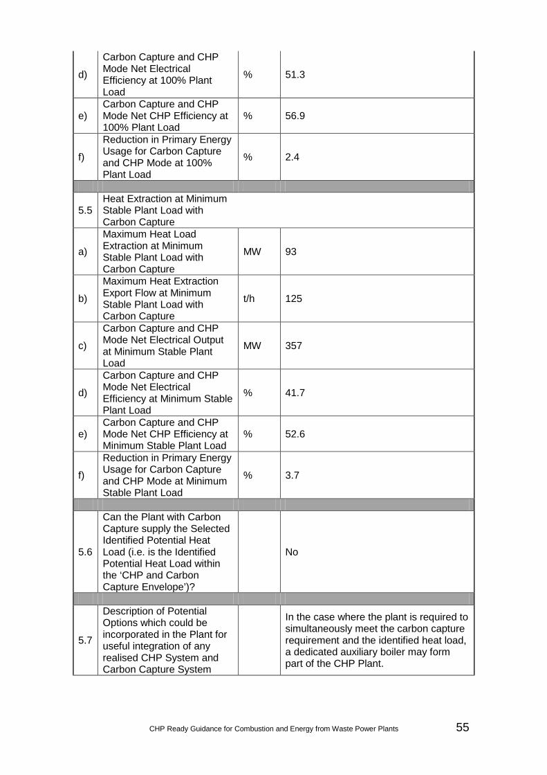
CHP Ready Guidance for Combustion and Energy from Waste Power Plants 55
d)
Carbon Capture and CHP Mode Net Electrical Efficiency at 100% Plant Load
% 51.3
e) Carbon Capture and CHP Mode Net CHP Efficiency at 100% Plant Load
% 56.9
f)
Reduction in Primary Energy Usage for Carbon Capture and CHP Mode at 100% Plant Load
% 2.4
5.5 Heat Extraction at Minimum Stable Plant Load with Carbon Capture
a)
Maximum Heat Load Extraction at Minimum Stable Plant Load with Carbon Capture
MW 93
b)
Maximum Heat Extraction Export Flow at Minimum Stable Plant Load with Carbon Capture
t/h 125
c)
Carbon Capture and CHP Mode Net Electrical Output at Minimum Stable Plant Load
MW 357
d)
Carbon Capture and CHP Mode Net Electrical Efficiency at Minimum Stable Plant Load
% 41.7
e) Carbon Capture and CHP Mode Net CHP Efficiency at Minimum Stable Plant Load
% 52.6
f)
Reduction in Primary Energy Usage for Carbon Capture and CHP Mode at Minimum Stable Plant Load
% 3.7
5.6
Can the Plant with Carbon Capture supply the Selected Identified Potential Heat Load (i.e. is the Identified Potential Heat Load within the ‘CHP and Carbon Capture Envelope’)?
No
5.7
Description of Potential Options which could be incorporated in the Plant for useful integration of any realised CHP System and Carbon Capture System
In the case where the plant is required to simultaneously meet the carbon capture requirement and the identified heat load, a dedicated auxiliary boiler may form part of the CHP Plant.

56 CHP Ready Guidance for Combustion and Energy from Waste Power Plants
Requirement 6: Economics of CHP-R
6.1 Economic Assessment of CHP-R Not required for the Case Study
BAT Assessment
Is the new plant a CHP plant at the outset (i.e. are there economically viable CHP opportunities at the outset)?
Not required for the Case Study
If not, is the new plant a CHP-R plant at the outset? Not required for the Case Study
Once the new plant is CHP-R, is it BAT? Not required for the Case Study

CHP Ready Guidance for Combustion and Energy from Waste Power Plants 57
CHP Envelope for Case Study 2
CHP and Carbon Capture Envelope for Case Study 2
0
100,000
200,000
300,000
400,000
500,000
600,000
700,000
800,000
900,000
1,000,000
0 50,000 100,000 150,000 200,000 250,000 300,000
Elec
tric
al P
ower
Out
put
(kW
)
Heat Load (kW)
MSL 60% Plant Load 80% Plant Load 100% Plant Load Operating Conditions
ACHPη = 50.2%PES = 0%
DCHPη = 57.6%PES = 0%
BCHPη = 63.1%PES = 8.1%
CCHPη = 68.5%PES = 8.1%
ECHPη = 66.3%PES = 6.5%
0
100,000
200,000
300,000
400,000
500,000
600,000
700,000
800,000
900,000
0 10,000 20,000 30,000 40,000 50,000 60,000 70,000 80,000 90,000 100,000
Elec
tric
al P
ower
Out
put
(kW
)
Heat Load (kW)
MSL 60% Plant Load 80% Plant Load 100% Plant Load Operating Conditions
ACHPη = 45.5%PES = 0%
DCHPη = 53.3%PES = 0%
BCHPη = 52.6%PES = 3.7%
CCHPη = 56.9%PES = 2.4%
EProposed Operating Conditions are outside CHP Envelope

Date:
Scale:
Sheet:
Designed:
Draw
n:
Approved:
Checked:
© C
opyright Parsons B
rinckerhoffTel:
44-(0)191-226-2000Fax:
44-(0)191-226-2104
A3
Am
ber Court
William
Arm
strong Drive
New
castle upon Tyne NE
4 7YQ
25/07/2012
Plot Date: 09/08/2012 11:41:26 K:\Projects\3511829A - CHP-R Case Study\Z. Drawings\1. Current\Civil\CS2.dwgFile Name:
Minikin, SandraLogin:
Title:C
lient:
Project:
Notes:
App
Chk
By
Description
Date
Rev
Project N
umber:
Revision:
Draw
ing Num
ber:
Project Number: Revision:Drawing Number:
ALM
EB
1:1000S
ITE LA
YO
UT PLAN
FOR
CA
SE
STU
DY 2
CC
GT PO
WE
R PLAN
T WITH
200MW
IND
US
TRIAL C
HP U
SE
EN
VIR
ON
ME
NT AG
ENC
Y
CH
P-R
GU
IDA
NC
E3511829A
CS 02
3511829A CS 02

CHP Ready Guidance for Combustion and Energy from Waste Power Plants 59
Case Study / Worked Example 3 #
Description
Units
Notes / Instructions
Requirement 1: Plant, Plant Location and Potential Heat Loads 1.1 Plant Name Case Study 3 1.2 Plant Description Biomass Plant
1.3 Plant Location (Postcode / GridRef) Not required for the Case Study
1.4 Factors Influencing Selection of Plant Location Not required for the Case Study
1.5 Operation of Plant
a) Proposed Operational Plant Load % 100
b) Thermal Input at Proposed Operational Plant Load MW 210
c) Net Electrical Output at Proposed Operational Plant Load
MW 75
d) Net Electrical Efficiency at Proposed Operational Plant Load
% 35.8
e) Maximum Plant Load % 100
f) Thermal Input at Maximum Plant Load MW 210
g) Net Electrical Output at Maximum Plant Load MW 75
h) Net Electrical Efficiency at Maximum Plant Load % 35.8
i) Minimum Stable Plant Load % 60
j) Thermal Input at Minimum Stable Plant Load MW 126
k) Net Electrical Output at Minimum Stable Plant Load MW 42
l) Net Electrical Efficiency at Minimum Stable Plant Load % 33.4
1.6 Identified Potential Heat Loads
45 MW District Heating 1.7 Selected Heat Load(s)
a) Category (e.g. Industrial / District Heating) District Heating
b) Maximum Heat Load Extraction Required MW 45
1.8 Export and Return Requirements of Heat Load
a) Description of Heat Load Extraction Hot water
b) Description of Heat Load Profile Variable

60 CHP Ready Guidance for Combustion and Energy from Waste Power Plants
c) Export Pressure bar a 5 d) Export Temperature °C 95 e) Export Flow t/h 970 f) Return Pressure bar a 3 g) Return Temperature °C 55 h) Return Flow t/h 970 Requirement 2: Identification of CHP Envelope
2.0 Comparative Efficiency of a Standalone Boiler for supplying the Heat Load
90 % LHV 90
2.1 Heat Extraction at 100% Plant Load
a) Maximum Heat Load Extraction at 100% Plant Load
MW 40
b) Maximum Heat Extraction Export Flow at 100% Plant Load
t/h 859
c) CHP Mode Net Electrical Output at 100% Plant Load MW 69.7
d) CHP Mode Net Electrical Efficiency at 100% Plant Load
% 33.2
e) CHP Mode Net CHP Efficiency at 100% Plant Load
% 52.3
f) Reduction in Primary Energy Usage for CHP Mode at 100% Plant Load
% 12.3
2.2 Heat Extraction at Minimum Stable Plant Load
a) Maximum Heat Load Extraction at Minimum Stable Plant Load
MW 18
b) Heat Extraction Export Flow at Minimum Stable Plant Load
t/h 387
c) CHP Mode Net Electrical Output at Minimum Stable Plant Load
MW 39.3
d) CHP Mode Net Electrical Efficiency at Minimum Stable Plant Load
% 31.3
e) CHP Mode Net CHP Efficiency at Minimum Stable Plant Load
% 45.6
f) Reduction in Primary Energy Usage for CHP Mode at Minimum Stable Plant Load
% 8.7

CHP Ready Guidance for Combustion and Energy from Waste Power Plants 61
2.3
Can the Plant supply the Selected Identified Potential Heat Load (i.e. is the Identified Potential Heat Load within the ‘CHP Envelope’)?
No (Go to Requirement 4)
Requirement 3: Operation of the Plant with the Selected Identified Heat Load
3.1 Proposed Operation of Plant with CHP
a) CHP Mode Net Electrical Output at Proposed Operational Plant Load
MW N / A
b) CHP Mode Net Electrical Efficiency at Proposed Operational Plant Load
% N / A
c) CHP Mode Net CHP Efficiency at Proposed Operational Plant Load
% N / A
d)
Reduction in Net Electrical Output for CHP Mode at Proposed Operational Plant Load
MW N / A
e)
Reduction in Net Electrical Efficiency for CHP Mode at Proposed Operational Plant Load
% N / A
f)
Reduction in Primary Energy Usage for CHP Mode at Proposed Operational Plant Load
% N / A
g) Z Ratio N / A Requirement 4: Technical Provisions and Space Requirements
4.1 Description of Likely Suitable Extraction Points
An amount of steam for the District Heating System could be supplied from the bleed steam lines for the LP feedwater heaters, downstream of the non return valves.
4.2
Description of Potential Options which could be incorporated in the Plant, should a CHP Opportunity be realised outside the 'CHP Envelope'
Additional amounts of steam could be generated from a stand-by boiler.

62 CHP Ready Guidance for Combustion and Energy from Waste Power Plants
4.3
Description of how the future Costs and Burdens associated with supplying the Identified Heat Load / Potential CHP Opportunity have been minimised through the implementation of an appropriate CHP-R design
Not required for the Case Study
4.4
Provision of Site Layout of the Plant, indicating Available Space which could be made available for CHP-R
Please see Layout CS 03. The District Heating System will (likely) include: extraction piping; control and shut-off valves, and actuators; a Pressure Reduction and De-superheating Station; District Heaters; District Heating supply and return lines; condensate return piping (to the condensate header); interconnecting piping; drains; pipe bridges / supports; and Control and Instrumentation / electrical connections. A Stand-by Boiler is also included. Provision is also made for possible extension of the Water Treatment Plant.
Requirement 5: Integration of CHP and Carbon Capture
5.1 Is the Plant required to be CCR? No
5.2 Export and Return Requirements Identified for Carbon Capture
100% Plant Load
a) Heat Load Extraction for Carbon Capture at 100% Plant Load
MW N / A
b) Description of Heat Export (e.g. Steam / Hot Water) N / A
c) Export Pressure bar a N / A d) Export Temperature °C N / A e) Export Flow t/h N / A f) Return Pressure bar a N / A g) Return Temperature °C N / A h) Return Flow t/h N / A
i) Likely Suitable Extraction Points N / A
Minimum Stable Plant Load
j) Heat Load Extraction for Carbon Capture at Minimum Stable Plant Load
MW N / A

CHP Ready Guidance for Combustion and Energy from Waste Power Plants 63
k) Description of Heat Export (e.g. Steam / Hot Water) N / A
l) Export Pressure bar a N / A m) Export Temperature °C N / A n) Export Flow t/h N / A o) Return Pressure bar a N / A p) Return Temperature °C N / A q) Return Flow t/h N / A
r) Likely Suitable Extraction Points N / A
5.3 Operation of Plant with Carbon Capture (without CHP)
a) Maximum Plant Load with Carbon Capture % N / A
b) Carbon Capture Mode Thermal Input at Maximum Plant Load
MW N / A
c) Carbon Capture Mode Net Electrical Output at Maximum Plant Load
MW N / A
d) Carbon Capture Mode Net Electrical Efficiency at Maximum Plant Load
% N / A
e) Minimum Stable Plant Load with CCS % N / A
f) Carbon Capture Mode CCS Thermal Input at Minimum Stable Plant Load
MW N / A
g) Carbon Capture Mode Net Electrical Output at Minimum Stable Plant Load
MW N / A
h) Carbon Capture Mode Net Electrical Efficiency at Minimum Stable Plant Load
% N / A
5.4 Heat Extraction for CHP at 100% Plant Load with Carbon Capture
a)
Maximum Heat Load Extraction at 100% Plant Load with Carbon Capture [H]
MW N / A
b) Maximum Heat Extraction Export Flow at 100% Plant Load with Carbon Capture
t/h N / A
c) Carbon Capture and CHP Mode Net Electrical Output at 100% Plant Load
MW N / A
d)
Carbon Capture and CHP Mode Net Electrical Efficiency at 100% Plant Load
% N / A

64 CHP Ready Guidance for Combustion and Energy from Waste Power Plants
e) Carbon Capture and CHP Mode Net CHP Efficiency at 100% Plant Load
% N / A
f)
Reduction in Primary Energy Usage for Carbon Capture and CHP Mode at 100% Plant Load
% N / A
5.5 Heat Extraction at Minimum Stable Plant Load with Carbon Capture
a)
Maximum Heat Load Extraction at Minimum Stable Plant Load with Carbon Capture
MW N / A
b)
Maximum Heat Extraction Export Flow at Minimum Stable Plant Load with Carbon Capture
t/h N / A
c)
Carbon Capture and CHP Mode Net Electrical Output at Minimum Stable Plant Load
MW N / A
d)
Carbon Capture and CHP Mode Net Electrical Efficiency at Minimum Stable Plant Load
% N / A
e) Carbon Capture and CHP Mode Net CHP Efficiency at Minimum Stable Plant Load
% N / A
f)
Reduction in Primary Energy Usage for Carbon Capture and CHP Mode at Minimum Stable Plant Load
% N / A
5.6
Can the Plant with Carbon Capture supply the Selected Identified Potential Heat Load (i.e. is the Identified Potential Heat Load within the ‘CHP and Carbon Capture Envelope’)?
N / A
5.7
Description of Potential Options which could be incorporated in the Plant for useful integration of any realised CHP System and Carbon Capture System
N / A
Requirement 6: Economics of CHP-R
6.1 Economic Assessment of CHP-R Not required for the Case Study

CHP Ready Guidance for Combustion and Energy from Waste Power Plants 65
BAT Assessment
Is the new plant a CHP plant at the outset (i.e. are there economically viable CHP opportunities at the outset)?
Not required for the Case Study
If not, is the new plant a CHP-R plant at the outset? Not required for the Case Study
Once the new plant is CHP-R, is it BAT? Not required for the Case Study

66 CHP Ready Guidance for Combustion and Energy from Waste Power Plants
CHP Envelope for Case Study 3
0
10,000
20,000
30,000
40,000
50,000
60,000
70,000
80,000
0 5,000 10,000 15,000 20,000 25,000 30,000 35,000 40,000 45,000
Elec
tric
al P
ower
Out
put
(kW
)
Heat Load (kW)
MSL 80% Plant Load 100% Plant Load Operating Conditions
ACHPη = 33.4%PES = 0%
DCHPη = 35.8%PES = 0%
BCHPη = 45.6%PES = 8.7%
CCHPη = 52.3%PES = 12.3%
EProposed Operating Conditions are outside CHP Envelope

Date:
Scale:
Sheet:
Designed:
Draw
n:
Approved:
Checked:
© C
opyright Parsons B
rinckerhoffTel:
44-(0)191-226-2000Fax:
44-(0)191-226-2104
A3
Am
ber Court
William
Arm
strong Drive
New
castle upon Tyne NE
4 7YQ
01/08/2012
Plot Date: 09/08/2012 11:42:20 K:\Projects\3511829A - CHP-R Case Study\Z. Drawings\1. Current\Civil\CS3.dwgFile Name:
Minikin, SandraLogin:
Title:C
lient:
Project:
Notes:
App
Chk
By
Description
Date
Rev
Project N
umber:
Revision:
Draw
ing Num
ber:
Project Number: Revision:Drawing Number:
ALM
EB
1:1000S
ITE LA
YO
UT PLAN
FOR
CA
SE
STU
DY 3
BIO
MA
SS
PO
WE
R PLAN
T WITH
45MW
OF D
ISTR
ICT H
EATING
EN
VIR
ON
ME
NT AG
ENC
Y
CH
P-R
GU
IDA
NC
E3511829A
CS 03
3511829A CS 03

68 CHP Ready Guidance for Combustion and Energy from Waste Power Plants
Case Study / Worked Example 4 #
Description
Units
Notes / Instructions
Requirement 1: Plant, Plant Location and Potential Heat Loads 1.1 Plant Name Case Study 4 1.2 Plant Description Energy from Waste Plant
1.3 Plant Location (Postcode / GridRef) Not required for the Case Study
1.4 Factors Influencing Selection of Plant Location Not required for the Case Study
1.5 Operation of Plant
a) Proposed Operational Plant Load % 100
b) Thermal Input at Proposed Operational Plant Load MW 84
c) Net Electrical Output at Proposed Operational Plant Load
MW 25
d) Net Electrical Efficiency at Proposed Operational Plant Load
% 29.7
e) Maximum Plant Load % 100
f) Thermal Input at Maximum Plant Load MW 84
g) Net Electrical Output at Maximum Plant Load MW 25
h) Net Electrical Efficiency at Maximum Plant Load % 29.7
i) Minimum Stable Plant Load % 60
j) Thermal Input at Minimum Stable Plant Load MW 50.5
k) Net Electrical Output at Minimum Stable Plant Load MW 13.6
l) Net Electrical Efficiency at Minimum Stable Plant Load % 26.9
1.6 Identified Potential Heat Loads
5 MW District Heating 1.7 Selected Heat Load(s)
a) Category (e.g. Industrial / District Heating) District Heating
b) Maximum Heat Load Extraction Required MW 5
1.8 Export and Return Requirements of Heat Load
a) Description of Heat Load Extraction Hot water
b) Description of Heat Load Profile Constant

CHP Ready Guidance for Combustion and Energy from Waste Power Plants 69
c) Export Pressure bar a 5 d) Export Temperature °C 95 e) Export Flow t/h 110 f) Return Pressure bar a 3 g) Return Temperature °C 55 h) Return Flow t/h 110 Requirement 2: Identification of CHP Envelope
2.0 Comparative Efficiency of a Standalone Boiler for supplying the Heat Load
90 % LHV 90
2.1 Heat Extraction at 100% Plant Load
a) Maximum Heat Load Extraction at 100% Plant Load
MW 20
b) Maximum Heat Extraction Export Flow at 100% Plant Load
t/h 430
c) CHP Mode Net Electrical Output at 100% Plant Load MW 22
d) CHP Mode Net Electrical Efficiency at 100% Plant Load
% 26.1
e) CHP Mode Net CHP Efficiency at 100% Plant Load
% 49.9
f) Reduction in Primary Energy Usage for CHP Mode at 100% Plant Load
% 12.6
2.2 Heat Extraction at Minimum Stable Plant Load
a) Maximum Heat Load Extraction at Minimum Stable Plant Load
MW 10
b) Heat Extraction Export Flow at Minimum Stable Plant Load
t/h 220
c) CHP Mode Net Electrical Output at Minimum Stable Plant Load
MW 11.9
d) CHP Mode Net Electrical Efficiency at Minimum Stable Plant Load
% 23.5
e) CHP Mode Net CHP Efficiency at Minimum Stable Plant Load
% 43.8
f) Reduction in Primary Energy Usage for CHP Mode at Minimum Stable Plant Load
% 9.7

70 CHP Ready Guidance for Combustion and Energy from Waste Power Plants
2.3
Can the Plant supply the Selected Identified Potential Heat Load (i.e. is the Identified Potential Heat Load within the ‘CHP Envelope’)?
Yes
Requirement 3: Operation of the Plant with the Selected Identified Heat Load
3.1 Proposed Operation of Plant with CHP
a) CHP Mode Net Electrical Output at Proposed Operational Plant Load
MW 24
b) CHP Mode Net Electrical Efficiency at Proposed Operational Plant Load
% 28.8
c) CHP Mode Net CHP Efficiency at Proposed Operational Plant Load
% 34.8
d)
Reduction in Net Electrical Output for CHP Mode at Proposed Operational Plant Load
MW 1
e)
Reduction in Net Electrical Efficiency for CHP Mode at Proposed Operational Plant Load
% 3.0
f)
Reduction in Primary Energy Usage for CHP Mode at Proposed Operational Plant Load
% 3.5
g) Z Ratio 5.0 Requirement 4: Technical Provisions and Space Requirements
4.1 Description of Likely Suitable Extraction Points
Steam for the District Heating System could be supplied from the bleed steam lines for the LP feedwater heaters, downstream of the non return valves.
4.2
Description of Potential Options which could be incorporated in the Plant, should a CHP Opportunity be realised outside the 'CHP Envelope'
N / A (CHP opportunity lies within the CHP Envelope)
4.3
Description of how the future Costs and Burdens associated with supplying the Identified Heat Load / Potential CHP Opportunity have been minimised through the implementation of an appropriate CHP-R design
Not required for the Case Study

CHP Ready Guidance for Combustion and Energy from Waste Power Plants 71
4.4
Provision of Site Layout of the Plant, indicating Available Space which could be made available for CHP-R
Please see Layout CS 04. The District Heating System will (likely) include: extraction piping; control and shut-off valves, and actuators; a Pressure Reduction and De-superheating Station; District Heaters; District Heating supply and return lines; condensate return piping (to the condensate header); interconnecting piping; drains; pipe bridges / supports; and Control and Instrumentation / electrical connections. A Stand-by Boiler is also included. Provision is also made for possible extension of the Water Treatment Plant.
Requirement 5: Integration of CHP and Carbon Capture
5.1 Is the Plant required to be CCR? No
5.2 Export and Return Requirements Identified for Carbon Capture
100% Plant Load
a) Heat Load Extraction for Carbon Capture at 100% Plant Load
MW N / A
b) Description of Heat Export (e.g. Steam / Hot Water) N / A
c) Export Pressure bar a N / A d) Export Temperature °C N / A e) Export Flow t/h N / A f) Return Pressure bar a N / A g) Return Temperature °C N / A h) Return Flow t/h N / A
i) Likely Suitable Extraction Points N / A
Minimum Stable Plant Load
j) Heat Load Extraction for Carbon Capture at Minimum Stable Plant Load
MW N / A
k) Description of Heat Export (e.g. Steam / Hot Water) N / A
l) Export Pressure bar a N / A m) Export Temperature °C N / A n) Export Flow t/h N / A o) Return Pressure bar a N / A p) Return Temperature °C N / A q) Return Flow t/h N / A

72 CHP Ready Guidance for Combustion and Energy from Waste Power Plants
r) Likely Suitable Extraction Points N / A
5.3 Operation of Plant with Carbon Capture (without CHP)
a) Maximum Plant Load with Carbon Capture % N / A
b) Carbon Capture Mode Thermal Input at Maximum Plant Load
MW N / A
c) Carbon Capture Mode Net Electrical Output at Maximum Plant Load
MW N / A
d) Carbon Capture Mode Net Electrical Efficiency at Maximum Plant Load
% N / A
e) Minimum Stable Plant Load with CCS % N / A
f) Carbon Capture Mode CCS Thermal Input at Minimum Stable Plant Load
MW N / A
g) Carbon Capture Mode Net Electrical Output at Minimum Stable Plant Load
MW N / A
h) Carbon Capture Mode Net Electrical Efficiency at Minimum Stable Plant Load
% N / A
5.4 Heat Extraction for CHP at 100% Plant Load with Carbon Capture
a)
Maximum Heat Load Extraction at 100% Plant Load with Carbon Capture [H]
MW N / A
b) Maximum Heat Extraction Export Flow at 100% Plant Load with Carbon Capture
t/h N / A
c) Carbon Capture and CHP Mode Net Electrical Output at 100% Plant Load
MW N / A
d)
Carbon Capture and CHP Mode Net Electrical Efficiency at 100% Plant Load
% N / A
e) Carbon Capture and CHP Mode Net CHP Efficiency at 100% Plant Load
% N / A
f)
Reduction in Primary Energy Usage for Carbon Capture and CHP Mode at 100% Plant Load
% N / A

CHP Ready Guidance for Combustion and Energy from Waste Power Plants 73
5.5 Heat Extraction at Minimum Stable Plant Load with Carbon Capture
a)
Maximum Heat Load Extraction at Minimum Stable Plant Load with Carbon Capture
MW N / A
b)
Maximum Heat Extraction Export Flow at Minimum Stable Plant Load with Carbon Capture
t/h N / A
c)
Carbon Capture and CHP Mode Net Electrical Output at Minimum Stable Plant Load
MW N / A
d)
Carbon Capture and CHP Mode Net Electrical Efficiency at Minimum Stable Plant Load
% N / A
e) Carbon Capture and CHP Mode Net CHP Efficiency at Minimum Stable Plant Load
% N / A
f)
Reduction in Primary Energy Usage for Carbon Capture and CHP Mode at Minimum Stable Plant Load
% N / A
5.6
Can the Plant with Carbon Capture supply the Selected Identified Potential Heat Load (i.e. is the Identified Potential Heat Load within the ‘CHP and Carbon Capture Envelope’)?
N / A
5.7
Description of Potential Options which could be incorporated in the Plant for useful integration of any realised CHP System and Carbon Capture System
N / A
Requirement 6: Economics of CHP-R
6.1 Economic Assessment of CHP-R Not required for the Case Study
BAT Assessment
Is the new plant a CHP plant at the outset (i.e. are there economically viable CHP opportunities at the outset)?
Not required for the Case Study
If not, is the new plant a CHP-R plant at the outset? Not required for the Case Study

74 CHP Ready Guidance for Combustion and Energy from Waste Power Plants
Once the new plant is CHP-R, is it BAT? Not required for the Case Study

CHP Ready Guidance for Combustion and Energy from Waste Power Plants 75
CHP Envelope for Case Study 4

Date:
Scale:
Sheet:
Designed:
Draw
n:
Approved:
Checked:
© C
opyright Parsons B
rinckerhoffTel:
44-(0)191-226-2000Fax:
44-(0)191-226-2104
A3
Am
ber Court
William
Arm
strong Drive
New
castle upon Tyne NE
4 7YQ
01/08/2012
Plot Date: 09/08/2012 11:49:36 K:\Projects\3511829A - CHP-R Case Study\Z. Drawings\1. Current\Civil\CS4.dwgFile Name:
Minikin, SandraLogin:
Title:C
lient:
Project:
Notes:
App
Chk
By
Description
Date
Rev
Project N
umber:
Revision:
Draw
ing Num
ber:
Project Number: Revision:Drawing Number:
ALM
EB
1:1000S
ITE LA
YO
UT PLAN
FOR
CA
SE
STU
DY 4
EN
VIR
ON
ME
NT AG
ENC
Y
CH
P-R
GU
IDA
NC
E3511829A
CS04
3511829A CS04

CHP Ready Guidance for Combustion and Energy from Waste Power Plants 77
Case Study / Worked Example 5a #
Description
Units
Notes / Instructions
Requirement 1: Plant, Plant Location and Potential Heat Loads 1.1 Plant Name Case Study 5a
1.2 Plant Description
Plant comprises:
• Single-shaft (1 + 1) Configuration;
• No IP / LP crossover pipe present;
• Hybrid Cooling; and
• UK ambient conditions.
1.3 Plant Location (Postcode / GridRef) Not required for the Case Study
1.4 Factors Influencing Selection of Plant Location Not required for the Case Study
1.5 Operation of Plant
a) Proposed Operational Plant Load % 100
b) Thermal Input at Proposed Operational Plant Load MW 771
c) Net Electrical Output at Proposed Operational Plant Load
MW 446.5
d) Net Electrical Efficiency at Proposed Operational Plant Load
% 57.9
e) Maximum Plant Load % 100
f) Thermal Input at Maximum Plant Load MW 771
g) Net Electrical Output at Maximum Plant Load MW 446.5
h) Net Electrical Efficiency at Maximum Plant Load % 57.9
i) Minimum Stable Plant Load % 40
j) Thermal Input at Minimum Stable Plant Load MW 427
k) Net Electrical Output at Minimum Stable Plant Load MW 215
l) Net Electrical Efficiency at Minimum Stable Plant Load % 50.4
1.6 Identified Potential Heat Loads
50 MW District Heating 1.7 Selected Heat Load(s)
a) Category (e.g. Industrial / District Heating) District Heating

78 CHP Ready Guidance for Combustion and Energy from Waste Power Plants
b) Maximum Heat Load Extraction Required MW 50
1.8 Export and Return Requirements of Heat Load
a) Description of Heat Load Extraction Hot water
b) Description of Heat Load Profile Constant
c) Export Pressure bar a 5 d) Export Temperature °C 95 e) Export Flow t/h 1075 f) Return Pressure bar a 3 g) Return Temperature °C 55 h) Return Flow t/h 1075 Requirement 2: Identification of CHP Envelope
2.0 Comparative Efficiency of a Standalone Boiler for supplying the Heat Load
90 % LHV 90
2.1 Heat Extraction at 100% Plant Load
a) Maximum Heat Load Extraction at 100% Plant Load
MW 151
b) Maximum Heat Extraction Export Flow at 100% Plant Load
t/h 3249
c) CHP Mode Net Electrical Output at 100% Plant Load MW 386
d) CHP Mode Net Electrical Efficiency at 100% Plant Load
% 50.1
e) CHP Mode Net CHP Efficiency at 100% Plant Load
% 69.7
f) Reduction in Primary Energy Usage for CHP Mode at 100% Plant Load
% 7.7
2.2 Heat Extraction at Minimum Stable Plant Load
a) Maximum Heat Load Extraction at Minimum Stable Plant Load
MW 77
b) Heat Extraction Export Flow at Minimum Stable Plant Load
t/h 1651
c) CHP Mode Net Electrical Output at Minimum Stable Plant Load
MW 184

CHP Ready Guidance for Combustion and Energy from Waste Power Plants 79
d) CHP Mode Net Electrical Efficiency at Minimum Stable Plant Load
% 43.2
e) CHP Mode Net CHP Efficiency at Minimum Stable Plant Load
% 61.2
f) Reduction in Primary Energy Usage for CHP Mode at Minimum Stable Plant Load
% 5.4
2.3
Can the Plant supply the Selected Identified Potential Heat Load (i.e. is the Identified Potential Heat Load within the ‘CHP Envelope’)?
Yes
Requirement 3: Operation of the Plant with the Selected Identified Heat Load
3.1 Proposed Operation of Plant with CHP
a) CHP Mode Net Electrical Output at Proposed Operational Plant Load
MW 424
b) CHP Mode Net Electrical Efficiency at Proposed Operational Plant Load
% 55.0
c) CHP Mode Net CHP Efficiency at Proposed Operational Plant Load
% 61.5
d)
Reduction in Net Electrical Output for CHP Mode at Proposed Operational Plant Load
MW 22.7
e)
Reduction in Net Electrical Efficiency for CHP Mode at Proposed Operational Plant Load
% 5.1
f)
Reduction in Primary Energy Usage for CHP Mode at Proposed Operational Plant Load
% 2.1
g) Z Ratio 2.2 Requirement 4: Technical Provisions and Space Requirements
4.1 Description of Likely Suitable Extraction Points
Steam cannot be readily extracted from the IP turbine exit. Therefore, steam is extracted from the cold reheat pipe, passed through a let-down station and supplied to the District Heating System.

80 CHP Ready Guidance for Combustion and Energy from Waste Power Plants
4.2
Description of Potential Options which could be incorporated in the Plant, should a CHP Opportunity be realised outside the 'CHP Envelope'
N / A (CHP opportunity lies within the CHP Envelope)
4.3
Description of how the future Costs and Burdens associated with supplying the Identified Heat Load / Potential CHP Opportunity have been minimised through the implementation of an appropriate CHP-R design
Not required for the Case Study
4.4
Provision of Site Layout of the Plant, indicating Available Space which could be made available for CHP-R
No Site Layout is provided for Case Study 5a. However, a number of points are noted. The District Heating System would (likely) include: extraction piping; control and shut-off valves, and actuators; a Pressure Reduction and De-superheating Station; District Heaters; District Heating supply and return lines; condensate return piping (to the condensate header); interconnecting piping; drains; pipe bridges / supports; and Control and Instrumentation / electrical connections. A Stand-by Boiler would also be included. Provision would also be made for possible extension of the Water Treatment Plant.
Requirement 5: Integration of CHP and Carbon Capture
5.1 Is the Plant required to be CCR? Yes
5.2 Export and Return Requirements Identified for Carbon Capture
100% Plant Load
a) Heat Load Extraction for Carbon Capture at 100% Plant Load
MW 117
b) Description of Heat Export (e.g. Steam / Hot Water) Low pressure steam
c) Export Pressure bar a 3.4 d) Export Temperature °C 150 e) Export Flow t/h 193
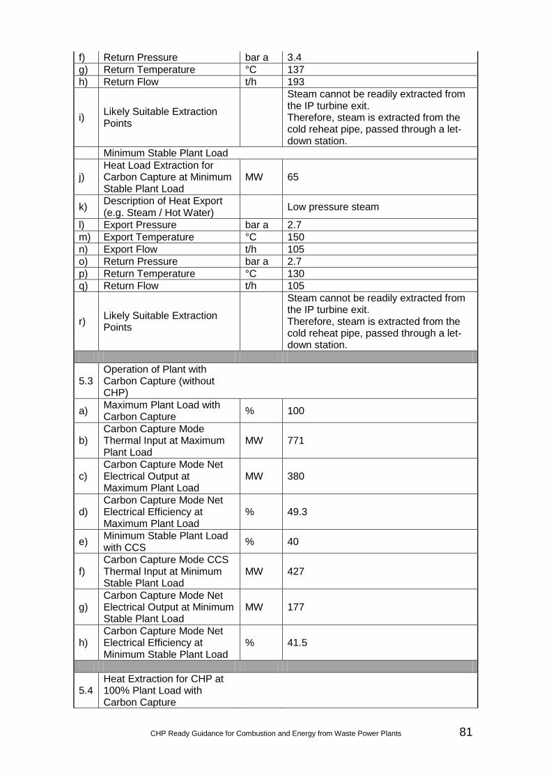
CHP Ready Guidance for Combustion and Energy from Waste Power Plants 81
f) Return Pressure bar a 3.4 g) Return Temperature °C 137 h) Return Flow t/h 193
i) Likely Suitable Extraction Points
Steam cannot be readily extracted from the IP turbine exit. Therefore, steam is extracted from the cold reheat pipe, passed through a let-down station.
Minimum Stable Plant Load
j) Heat Load Extraction for Carbon Capture at Minimum Stable Plant Load
MW 65
k) Description of Heat Export (e.g. Steam / Hot Water) Low pressure steam
l) Export Pressure bar a 2.7 m) Export Temperature °C 150 n) Export Flow t/h 105 o) Return Pressure bar a 2.7 p) Return Temperature °C 130 q) Return Flow t/h 105
r) Likely Suitable Extraction Points
Steam cannot be readily extracted from the IP turbine exit. Therefore, steam is extracted from the cold reheat pipe, passed through a let-down station.
5.3 Operation of Plant with Carbon Capture (without CHP)
a) Maximum Plant Load with Carbon Capture % 100
b) Carbon Capture Mode Thermal Input at Maximum Plant Load
MW 771
c) Carbon Capture Mode Net Electrical Output at Maximum Plant Load
MW 380
d) Carbon Capture Mode Net Electrical Efficiency at Maximum Plant Load
% 49.3
e) Minimum Stable Plant Load with CCS % 40
f) Carbon Capture Mode CCS Thermal Input at Minimum Stable Plant Load
MW 427
g) Carbon Capture Mode Net Electrical Output at Minimum Stable Plant Load
MW 177
h) Carbon Capture Mode Net Electrical Efficiency at Minimum Stable Plant Load
% 41.5
5.4 Heat Extraction for CHP at 100% Plant Load with Carbon Capture

82 CHP Ready Guidance for Combustion and Energy from Waste Power Plants
a)
Maximum Heat Load Extraction at 100% Plant Load with Carbon Capture [H]
MW 41
b) Maximum Heat Extraction Export Flow at 100% Plant Load with Carbon Capture
t/h 879
c) Carbon Capture and CHP Mode Net Electrical Output at 100% Plant Load
MW 362
d)
Carbon Capture and CHP Mode Net Electrical Efficiency at 100% Plant Load
% 47.0
e) Carbon Capture and CHP Mode Net CHP Efficiency at 100% Plant Load
% 52.3
f)
Reduction in Primary Energy Usage for Carbon Capture and CHP Mode at 100% Plant Load
% 1.3
5.5 Heat Extraction at Minimum Stable Plant Load with Carbon Capture
a)
Maximum Heat Load Extraction at Minimum Stable Plant Load with Carbon Capture
MW 17
b)
Maximum Heat Extraction Export Flow at Minimum Stable Plant Load with Carbon Capture
t/h 366
c)
Carbon Capture and CHP Mode Net Electrical Output at Minimum Stable Plant Load
MW 171
d)
Carbon Capture and CHP Mode Net Electrical Efficiency at Minimum Stable Plant Load
% 40.1
e) Carbon Capture and CHP Mode Net CHP Efficiency at Minimum Stable Plant Load
% 44.1
f)
Reduction in Primary Energy Usage for Carbon Capture and CHP Mode at Minimum Stable Plant Load
% 1.0

CHP Ready Guidance for Combustion and Energy from Waste Power Plants 83
5.6
Can the Plant with Carbon Capture supply the Selected Identified Potential Heat Load (i.e. is the Identified Potential Heat Load within the ‘CHP and Carbon Capture Envelope’)?
No
5.7
Description of Potential Options which could be incorporated in the Plant for useful integration of any realised CHP System and Carbon Capture System
In the case where the plant is required to simultaneously meet the carbon capture requirement and the identified heat load, a dedicated auxiliary boiler may form part of the CHP Plant.
Requirement 6: Economics of CHP-R
6.1 Economic Assessment of CHP-R Not required for the Case Study
BAT Assessment
Is the new plant a CHP plant at the outset (i.e. are there economically viable CHP opportunities at the outset)?
Not required for the Case Study
If not, is the new plant a CHP-R plant at the outset? Not required for the Case Study
Once the new plant is CHP-R, is it BAT? Not required for the Case Study

84 CHP Ready Guidance for Combustion and Energy from Waste Power Plants
CHP Envelope for Case Study 5a
CHP and Carbon Capture Envelope for Case Study 5a
0
50,000
100,000
150,000
200,000
250,000
300,000
350,000
400,000
450,000
500,000
0 25,000 50,000 75,000 100,000 125,000 150,000 175,000
Elec
trica
l Pow
er O
utpu
t (kW
)
Heat Load (kW)
MSL 60% Plant Load 80% Plant Load 100% Plant Load Operating Conditions
ACHPη= 50.4% PES = 0
DCHPη= 57.9%PES = 0 C
CHPη= 69.7%PES = 7.7%
BCHPη= 61.2%PES = 5.4%
ECHPη= 61.5%PES = 2.1%
0
50,000
100,000
150,000
200,000
250,000
300,000
350,000
400,000
0 5,000 10,000 15,000 20,000 25,000 30,000 35,000 40,000 45,000
Elec
tric
al P
ower
Out
put
(kW
)
Heat Load (kW)
50% Plant Load 60% Plant Load 80% Plant Load 100% Plant Load
ACHPη= 41.5% PES = 0
DCHPη= 49.3%PES = 0
CCHPη= 52.3%PES = 1.3%
BCHPη= 44.1%PES = 1.0%
EProposed Operating Conditions are outside CHP Envelope

CHP Ready Guidance for Combustion and Energy from Waste Power Plants 85
Case Study / Worked Example 5b #
Description
Units
Notes / Instructions
Requirement 1: Plant, Plant Location and Potential Heat Loads 1.1 Plant Name Case Study 5b
1.2 Plant Description
Plant comprises:
• Single-shaft (1 + 1) Configuration;
• Hybrid Cooling; and
• UK ambient conditions.
1.3 Plant Location (Postcode / GridRef) Not required for the Case Study
1.4 Factors Influencing Selection of Plant Location Not required for the Case Study
1.5 Operation of Plant
a) Proposed Operational Plant Load % 100
b) Thermal Input at Proposed Operational Plant Load MW 771
c) Net Electrical Output at Proposed Operational Plant Load
MW 446.5
d) Net Electrical Efficiency at Proposed Operational Plant Load
% 57.9
e) Maximum Plant Load % 100
f) Thermal Input at Maximum Plant Load MW 771
g) Net Electrical Output at Maximum Plant Load MW 446.5
h) Net Electrical Efficiency at Maximum Plant Load % 57.9
i) Minimum Stable Plant Load % 40
j) Thermal Input at Minimum Stable Plant Load MW 427
k) Net Electrical Output at Minimum Stable Plant Load MW 215
l) Net Electrical Efficiency at Minimum Stable Plant Load % 50.4
1.6 Identified Potential Heat Loads
50 MW District Heating 1.7 Selected Heat Load(s)
a) Category (e.g. Industrial / District Heating) District Heating
b) Maximum Heat Load Extraction Required MW 50
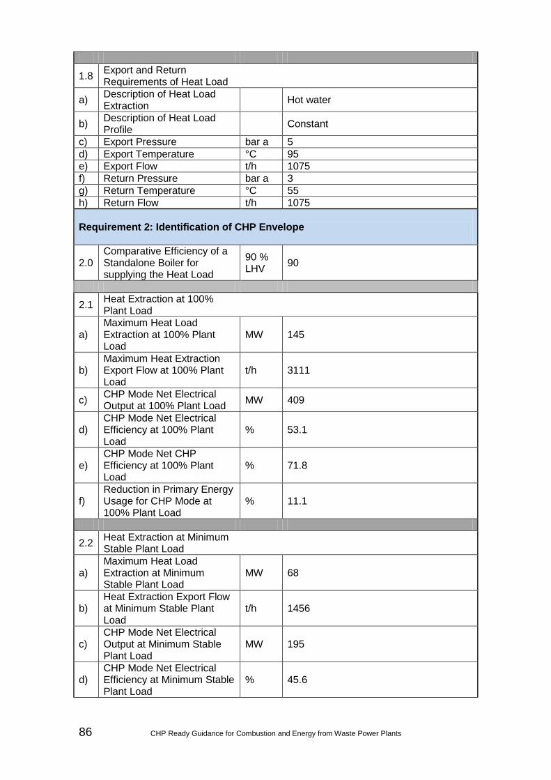
86 CHP Ready Guidance for Combustion and Energy from Waste Power Plants
1.8 Export and Return Requirements of Heat Load
a) Description of Heat Load Extraction Hot water
b) Description of Heat Load Profile Constant
c) Export Pressure bar a 5 d) Export Temperature °C 95 e) Export Flow t/h 1075 f) Return Pressure bar a 3 g) Return Temperature °C 55 h) Return Flow t/h 1075 Requirement 2: Identification of CHP Envelope
2.0 Comparative Efficiency of a Standalone Boiler for supplying the Heat Load
90 % LHV 90
2.1 Heat Extraction at 100% Plant Load
a) Maximum Heat Load Extraction at 100% Plant Load
MW 145
b) Maximum Heat Extraction Export Flow at 100% Plant Load
t/h 3111
c) CHP Mode Net Electrical Output at 100% Plant Load MW 409
d) CHP Mode Net Electrical Efficiency at 100% Plant Load
% 53.1
e) CHP Mode Net CHP Efficiency at 100% Plant Load
% 71.8
f) Reduction in Primary Energy Usage for CHP Mode at 100% Plant Load
% 11.1
2.2 Heat Extraction at Minimum Stable Plant Load
a) Maximum Heat Load Extraction at Minimum Stable Plant Load
MW 68
b) Heat Extraction Export Flow at Minimum Stable Plant Load
t/h 1456
c) CHP Mode Net Electrical Output at Minimum Stable Plant Load
MW 195
d) CHP Mode Net Electrical Efficiency at Minimum Stable Plant Load
% 45.6
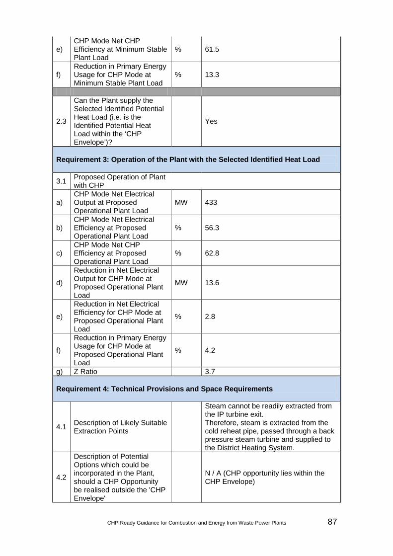
CHP Ready Guidance for Combustion and Energy from Waste Power Plants 87
e) CHP Mode Net CHP Efficiency at Minimum Stable Plant Load
% 61.5
f) Reduction in Primary Energy Usage for CHP Mode at Minimum Stable Plant Load
% 13.3
2.3
Can the Plant supply the Selected Identified Potential Heat Load (i.e. is the Identified Potential Heat Load within the ‘CHP Envelope’)?
Yes
Requirement 3: Operation of the Plant with the Selected Identified Heat Load
3.1 Proposed Operation of Plant with CHP
a) CHP Mode Net Electrical Output at Proposed Operational Plant Load
MW 433
b) CHP Mode Net Electrical Efficiency at Proposed Operational Plant Load
% 56.3
c) CHP Mode Net CHP Efficiency at Proposed Operational Plant Load
% 62.8
d)
Reduction in Net Electrical Output for CHP Mode at Proposed Operational Plant Load
MW 13.6
e)
Reduction in Net Electrical Efficiency for CHP Mode at Proposed Operational Plant Load
% 2.8
f)
Reduction in Primary Energy Usage for CHP Mode at Proposed Operational Plant Load
% 4.2
g) Z Ratio 3.7 Requirement 4: Technical Provisions and Space Requirements
4.1 Description of Likely Suitable Extraction Points
Steam cannot be readily extracted from the IP turbine exit. Therefore, steam is extracted from the cold reheat pipe, passed through a back pressure steam turbine and supplied to the District Heating System.
4.2
Description of Potential Options which could be incorporated in the Plant, should a CHP Opportunity be realised outside the 'CHP Envelope'
N / A (CHP opportunity lies within the CHP Envelope)
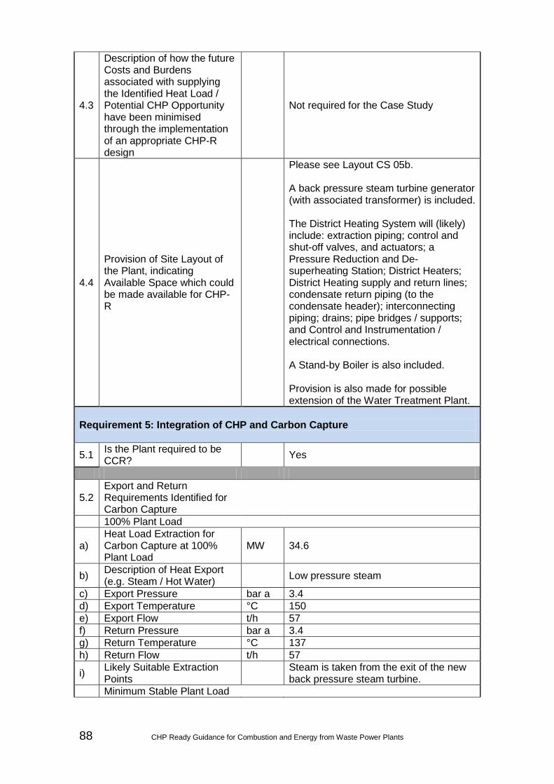
88 CHP Ready Guidance for Combustion and Energy from Waste Power Plants
4.3
Description of how the future Costs and Burdens associated with supplying the Identified Heat Load / Potential CHP Opportunity have been minimised through the implementation of an appropriate CHP-R design
Not required for the Case Study
4.4
Provision of Site Layout of the Plant, indicating Available Space which could be made available for CHP-R
Please see Layout CS 05b. A back pressure steam turbine generator (with associated transformer) is included. The District Heating System will (likely) include: extraction piping; control and shut-off valves, and actuators; a Pressure Reduction and De-superheating Station; District Heaters; District Heating supply and return lines; condensate return piping (to the condensate header); interconnecting piping; drains; pipe bridges / supports; and Control and Instrumentation / electrical connections. A Stand-by Boiler is also included. Provision is also made for possible extension of the Water Treatment Plant.
Requirement 5: Integration of CHP and Carbon Capture
5.1 Is the Plant required to be CCR? Yes
5.2 Export and Return Requirements Identified for Carbon Capture
100% Plant Load
a) Heat Load Extraction for Carbon Capture at 100% Plant Load
MW 34.6
b) Description of Heat Export (e.g. Steam / Hot Water) Low pressure steam
c) Export Pressure bar a 3.4 d) Export Temperature °C 150 e) Export Flow t/h 57 f) Return Pressure bar a 3.4 g) Return Temperature °C 137 h) Return Flow t/h 57
i) Likely Suitable Extraction Points Steam is taken from the exit of the new
back pressure steam turbine. Minimum Stable Plant Load
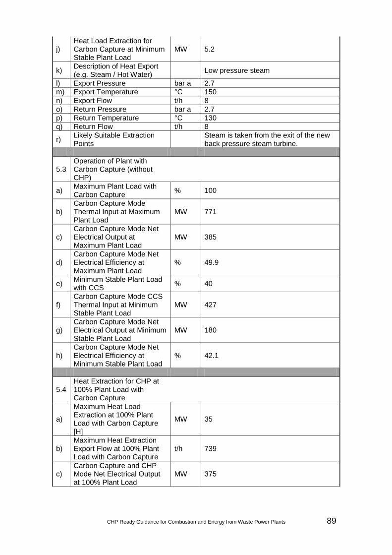
CHP Ready Guidance for Combustion and Energy from Waste Power Plants 89
j) Heat Load Extraction for Carbon Capture at Minimum Stable Plant Load
MW 5.2
k) Description of Heat Export (e.g. Steam / Hot Water) Low pressure steam
l) Export Pressure bar a 2.7 m) Export Temperature °C 150 n) Export Flow t/h 8 o) Return Pressure bar a 2.7 p) Return Temperature °C 130 q) Return Flow t/h 8
r) Likely Suitable Extraction Points Steam is taken from the exit of the new
back pressure steam turbine.
5.3 Operation of Plant with Carbon Capture (without CHP)
a) Maximum Plant Load with Carbon Capture % 100
b) Carbon Capture Mode Thermal Input at Maximum Plant Load
MW 771
c) Carbon Capture Mode Net Electrical Output at Maximum Plant Load
MW 385
d) Carbon Capture Mode Net Electrical Efficiency at Maximum Plant Load
% 49.9
e) Minimum Stable Plant Load with CCS % 40
f) Carbon Capture Mode CCS Thermal Input at Minimum Stable Plant Load
MW 427
g) Carbon Capture Mode Net Electrical Output at Minimum Stable Plant Load
MW 180
h) Carbon Capture Mode Net Electrical Efficiency at Minimum Stable Plant Load
% 42.1
5.4 Heat Extraction for CHP at 100% Plant Load with Carbon Capture
a)
Maximum Heat Load Extraction at 100% Plant Load with Carbon Capture [H]
MW 35
b) Maximum Heat Extraction Export Flow at 100% Plant Load with Carbon Capture
t/h 739
c) Carbon Capture and CHP Mode Net Electrical Output at 100% Plant Load
MW 375

90 CHP Ready Guidance for Combustion and Energy from Waste Power Plants
d)
Carbon Capture and CHP Mode Net Electrical Efficiency at 100% Plant Load
% 48.6
e) Carbon Capture and CHP Mode Net CHP Efficiency at 100% Plant Load
% 53.1
f)
Reduction in Primary Energy Usage for Carbon Capture and CHP Mode at 100% Plant Load
% 3.5
5.5 Heat Extraction at Minimum Stable Plant Load with Carbon Capture
a)
Maximum Heat Load Extraction at Minimum Stable Plant Load with Carbon Capture
MW 5
b)
Maximum Heat Extraction Export Flow at Minimum Stable Plant Load with Carbon Capture
t/h 112
c)
Carbon Capture and CHP Mode Net Electrical Output at Minimum Stable Plant Load
MW 178
d)
Carbon Capture and CHP Mode Net Electrical Efficiency at Minimum Stable Plant Load
% 41.7
e) Carbon Capture and CHP Mode Net CHP Efficiency at Minimum Stable Plant Load
% 42.9
f)
Reduction in Primary Energy Usage for Carbon Capture and CHP Mode at Minimum Stable Plant Load
% 0.4
5.6
Can the Plant with Carbon Capture supply the Selected Identified Potential Heat Load (i.e. is the Identified Potential Heat Load within the ‘CHP and Carbon Capture Envelope’)?
No
5.7
Description of Potential Options which could be incorporated in the Plant for useful integration of any realised CHP System and Carbon Capture System
In the case where the plant is required to simultaneously meet the carbon capture requirement and the identified heat load, a dedicated auxiliary boiler may form part of the CHP Plant.

CHP Ready Guidance for Combustion and Energy from Waste Power Plants 91
Requirement 6: Economics of CHP-R
6.1 Economic Assessment of CHP-R Not required for the Case Study
BAT Assessment
Is the new plant a CHP plant at the outset (i.e. are there economically viable CHP opportunities at the outset)?
Not required for the Case Study
If not, is the new plant a CHP-R plant at the outset? Not required for the Case Study
Once the new plant is CHP-R, is it BAT? Not required for the Case Study

92 CHP Ready Guidance for Combustion and Energy from Waste Power Plants
CHP Envelope for Case Study 5b
CHP and Carbon Capture Envelope for Case Study 5b
0
50,000
100,000
150,000
200,000
250,000
300,000
350,000
400,000
450,000
500,000
0 25,000 50,000 75,000 100,000 125,000 150,000 175,000
Elec
tric
al P
ower
Out
put
(kW
)
Heat Load (kW)
MSL 60% Plant Load 80% Plant Load 100% Plant Load Operating Condition
ACHPη= 50.4% PES = 0
DCHPη= 57.9%PES = 0 C
CHPη= 71.8%PES = 11.1%
BCHPη= 61.5%PES = 13.3%
ECHPη= 62.8%PES = 4.2%
0
50,000
100,000
150,000
200,000
250,000
300,000
350,000
400,000
450,000
0 5,000 10,000 15,000 20,000 25,000 30,000 35,000 40,000
Elec
tric
al P
ower
Out
put
(kW
)
Heat Load (kW)
MSL 60% Plant Load 80% Plant Load 100% Plant Load
EProposed Operating Conditions are outside CHP Envelope
ACHPη= 41.5% PES = 0
DCHPη= 49.3%PES = 0
CCHPη= 53.1%PES = 3.5%
BCHPη= 42.9%PES = 0.4%

Date:
Scale:
Sheet:
Designed:
Draw
n:
Approved:
Checked:
© C
opyright Parsons B
rinckerhoffTel:
44-(0)191-226-2000Fax:
44-(0)191-226-2104
A3
Am
ber Court
William
Arm
strong Drive
New
castle upon Tyne NE
4 7YQ
30/07/2012
Plot Date: 22/10/2012 14:15:40 K:\Projects\3511829A - CHP-R Case Study\Z. Drawings\1. Current\Civil\CS5.dwgFile Name:
Minikin, SandraLogin:
Title:C
lient:
Project:
Notes:
App
Chk
By
Description
Date
Rev
Project N
umber:
Revision:
Draw
ing Num
ber:
Project Number: Revision:Drawing Number:
ALM
EB
1:1250S
ITE LA
YO
UT PLAN
FOR
CA
SE
STU
DY
5C
CG
T POW
ER
PLAN
T WITH
ENVIR
ON
ME
NT AG
ENC
Y
CH
P-RG
UID
ANC
E3511829A
CS 05
1
3511829A CS 05 1

94 CHP Ready Guidance for Combustion and Energy from Waste Power Plants
Appendix C: Additional Economic Supporting Information An integral part of any BAT test is a consideration of the economic viability of the chosen option.
Qualitative Economic Screening Under Requirement 1, the CHP-R Assessment requires that there is a description of and search for the likely extent and nature of CHP opportunities (i.e. potential heat loads) in the area of the new plant. Following this, the CHP-R Assessment requires that there is an appropriate selection of heat loads to take forwards to the CHP-R Assessment. In terms of the 'appropriate selection of heat loads', this should be such that, wherever possible, 10% primary energy savings could be achieved in the future. However, where this is not possible, the selection of heat loads should be such that maximum primary energy savings could eventually be achieved whilst not necessarily meeting the criteria for Good Quality CHP. Accordingly, the appropriate selection of heat loads may include a discussion with the Environment Agency, potential heat load recipient(s), and / or a degree of qualitative economic screening. An example of a qualitative economic screening process is given here. However, it should be noted that this should not be considered to be the only way in which a qualitative economic screening can be undertaken, and therefore it would be the responsibility of the applicant / operator to justify the basis for their qualitative economic screening. Step 1: High Level Analysis of Likely Extent and Nature of CHP Opportunities in the Area The high level analysis of the likely extent and nature of CHP opportunities in the area should comprise a description of:
• Size / type of heat load and initial estimation of primary energy savings;
• Likelihood of CHP opportunity being realised;
• Likely requirement for on site works (giving consideration to additional land / space requirements); and
• Likely requirement for off site works (giving consideration to: additional land / space requirements; distance of CHP Load from Plant; and, terrain between CHP Load and Plant).
Step 2: Ranking of CHP Opportunities in the Area In terms of the factors listed under Step 1, a ranking of CHP opportunities in the area should be undertaken. The ranking (and subsequent) selection of heat loads should be such that, wherever possible, 10% primary energy savings could be achieved in the future. Therefore, where the initial estimation of primary energy savings is greater than 10%, this heat

CHP Ready Guidance for Combustion and Energy from Waste Power Plants 95
load (or heat loads) should automatically be taken forwards. However, it is accepted that this may not always be possible. In these cases, the selection of heat load (or heat loads) should be such that maximum primary energy savings could eventually be achieved whilst not necessarily meeting the criteria for Good Quality CHP. In terms of the remaining factors, an example of additional ranking criteria which can be used is provided in Table C.1.
TABLE C.1: DESCRIPTION OF ADDITIONAL RANKING CRITERIA
Likely High Level of Economic Viability
Likely Medium Level of Economic Viability
Likely Low Level of Economic Viability
Likelihood of CHP Opportunity being Raised
Within 5 Years Between 5 to 10 Years
Over 10 Years
Ranking 1 2 3 Requirement for On Site Works
Minimal Moderate Complex
Ranking 1 2 3 Requirement for Off Site Works
Minimal Moderate Complex
Ranking 1 2 3 Step3: Appropriate Selection of Heat Loads Based on Step 2, an appropriate selection of heat loads should be undertaken. A justification of this appropriate selection should be provided, which could be based on the analysis / ranking undertaken in Step 1 and Step 2. Also, the appropriate selection of heat loads may include a discussion with the Environment Agency and potential heat load recipient, and must be agreed with the Environment Agency.
Economics of CHP-R and CHP Further to the requirement for the new plant being CHP-R, the economic viability of actually realising a CHP scheme is an important consideration for:
• The first BAT test (i.e. when realising a CHP scheme at the outset); and
• The third BAT test (i.e. when carrying out periodic reviews of opportunities to realise CHP (both existing and new)).
For this reason, this CHP-R Guidance provides some suggestions on assessing and presenting the potential revenues and costs of the wider economics of CHP-R and CHP schemes. Accordingly, within the context of this CHP-R Guidance, the potential revenues and costs of being a CHP-R plant, converting a CHP-R plant to a CHP plant or a CHP plant are considered to include (but not necessarily be limited to):
96 CHP Ready Guidance for Combustion and Energy from Waste Power Plants
• Revenues / benefits associated with incentives and support measures for CHP, including17,18:
- Up to 1 April 2013, exemption (via Levy Exemption Certificates) from the Climate Change Levy of all fuel inputs to (and electricity outputs from) Good Quality CHP;
- Enhanced Capital Allowances for Good Quality CHP equipment / machinery in Non-Utility Sectors;
- Business Rates exemption for embedded CHP equipment / machinery; and,
- Support under the Renewables Obligation and / or Renewables Heat Incentive19 for some types of plant that incorporate CHP. .
• Costs associated with being a CHP-R plant, including:
- Upfront Studies;
- Modifications to 'standard' design (i.e. providing suitable extraction points); and,
- Additional land / space requirements.
• Costs associated with the modification / conversion to CHP plant, including:
- Modifications to CHP-R plant (e.g. implementing suitable extraction points);
- Modifications to existing plant items (e.g. pipe runs);
- Expansion of existing plant items (e.g. water treatment plant);
- Structural / civil works; and,
- Control and Instrumentation / Electrical works.
• Costs associated with new on site CHP equipment / plant, including:
- Additional equipment items (e.g. supply and return pipes, back-up boilers); and
- Additional plant items (e.g. valves, pumps, heat exchangers).
• Costs associated with the new off-site CHP equipment / plant, including:
- Additional equipment items (e.g. supply and return pipes);
- Additional plant items (e.g. valves, pumps);
- Structural / civil works;
- Control and Instrumentation / Electrical works; and
- Additional land / space requirements.
17 Adapted from Digest of UK Energy Statistics (DUKES) 2011 – Chapter 6 (Combined Heat and Power). 18 However, it should be noted that these measures may be subject to change as a results of changes in Government Policy. There is may be that additional incentives and support measures for plant which incorporate CHP may be available in the future. 19 At the time of writing, DECC are intending to consult on amendments to the Renewable Heat Incentive (RHI) tariff arrangements for renewable CHP plants which are not eligible for the "half Renewable Obligation Certificates uplift" which applies to plant accredited before 1 April 2013.

CHP Ready Guidance for Combustion and Energy from Waste Power Plants 97
It is noted that the EED contains guidance on conducting an economic assessment (i.e. a cost-benefit analysis). This is included at Part 2 of Annex IX. Furthermore, it is noted that there are a number of Documents available which contain guidance on conducting economic assessments. These Documents include:
• Annex K (Cost Benefit Analysis) of the Environment Agency H1 Guidance (Environmental Risk Assessment Framework);
• Appendix 4 (Appraisal of Energy Efficiency Techniques) of the Environment Agency H2 Guidance (Energy Efficiency); and,
• Paragraphs 62 to 69 of Carbon Capture Readiness (CCR): A Guidance Note for Section 36 Electricity Act, 1989 Consent Applications20.
The following suggested proposed structure incorporates elements from the above Documents. However, it should be noted that this should not be considered to be the only way in which an economic assessment can be undertaken, and therefore it would be the responsibility of the applicant / operator to justify the basis for their economic assessment.
• Outline
The economic assessment should be based on the parameters provided in the technical assessments of CHP-R (i.e. those in Requirement 2 to Requirement 5).
• Parameters taken into Account
The parameters for the economic assessment should be described. For the economic assessment, including the subsequent revenues and costs of the CHP scheme, the following parameters may be required: discount rate; assumed lifetime; fuel price; carbon price; heat price; amount of heat supplied; plant net electrical power output with and without CHP; proposed plant load factor; likely incentives and support measures for CHP; initial costs for the plant to be CHP-R (i.e. similar to those estimated in the second BAT test, as described in this CHP-R Guidance); subsequent costs to modify / convert the CHP-R plant to a CHP plant (including all associated on site and off site costs) (i.e. similar to those estimated in the second BAT test, as described in this CHP-R Guidance); and, reasonable estimates of when the revenues / costs would occur.
• Estimated Costs
Based on the above parameters, Table A4.3 (Template for the Presentation of Capital Costs) and Table A4.4 (Template for the Presentation of Operating Costs) of Appendix 4 (Appraisal of Energy Efficiency Techniques) of the Environment Agency H2 Guidance (Energy Efficiency) could be used as a template to estimate (for each identified option): the capital costs; the likely annual operating revenues; and, the average change in annual operating and maintenance costs. In using these Tables, the capital costs / operating revenues and costs are broken down into sufficient details to allow the major influences of each option to be clearly demonstrated. 20 Carbon Capture Readiness (CCR): A Guidance Note for Section 36 Electricity Act, 1989 Consent Applications. Crown Copyright URN 09D/819.

98 CHP Ready Guidance for Combustion and Energy from Waste Power Plants
• Methodology / Determining Economic Viability
The principles in use within the modelling should be described, and a comparison could be provided between costs of generation for the various options. Table A4.2 (Cost-Benefit Appraisal Summary) of Appendix 4 (Appraisal of Energy Efficiency Techniques) of the Environment Agency H2 Guidance (Energy Efficiency) could be used as a template. For example:
Non CHP Plant
CHP Plant (Option 1)
CHP Plant (Option 2)
Capital Costs (£) Potential Operating Revenues (£/year)
Operating Costs (£/year)
Life of Option Annual Costs / Savings with CHP21
N /A
Price of Electricity Annual Carbon Dioxide savings with CHP
N / A
A sensitivity analysis could then be undertaken (i.e. by varying the parameters which influence the annual costs / savings) to determine likely ranges which would ultimately allow an option to be economically viable. This could be used to give a measure of uncertainty within the modelling.
• Economic Assessment Summary
Based on the above, a clear summary of the economic assessment could be provided, indicating the likely ranges (in terms of costs of generation) which would ultimately allow an option for a CHP scheme to be economically viable
21 Based on one of the support measures to incentivise CHP.
CHP Ready Guidance for Combustion and Energy from Waste Power Plants 99
Appendix D: Additional Technical Supporting Information Based on the CHP-R Assessment Form Point 4.1 (Description of Likely Suitable Extraction Points), it is required that likely suitable extraction points are described and a suitable method (or methods) or extraction are identified. The potential for a plant to be converted to supply heat in the future (whether it is to either a district heat network or an industrial process) depends upon: the type of plant being considered (i.e. whether it is conventional steam or a CCGT); the steam cycle configuration; and, the steam turbine configuration. For example:
• The steam cycle can be:
- With or without reheat; and,
- (For CCGT) it can be one, two or three pressure.
• The steam turbine can:
- Have a lateral exhaust (side or down), or an axial exhaust;
- Have different casing arrangements (i.e. single and multi).
The following information contains a range of examples which represent a range of configurations for illustrative purposes. However, it should be noted that this range of examples is not intended to be exhaustive. Additionally, the potential steam sources shown are based on typical arrangements without consideration of CHP (i.e. they are representative of plants which are initially required to generate electrical power). However, the future extraction points are described for the purposes of demonstrating CHP-R.
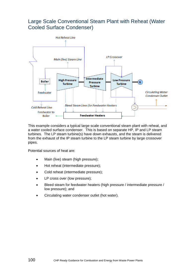
100 CHP Ready Guidance for Combustion and Energy from Waste Power Plants
Large Scale Conventional Steam Plant with Reheat (Water Cooled Surface Condenser)
This example considers a typical large scale conventional steam plant with reheat, and a water cooled surface condenser. This is based on separate HP, IP and LP steam turbines. The LP steam turbine(s) have down exhausts, and the steam is delivered from the exhaust of the IP steam turbine to the LP steam turbine by large crossover pipes. Potential sources of heat are:
• Main (live) steam (high pressure);
• Hot reheat (intermediate pressure);
• Cold reheat (intermediate pressure);
• LP cross over (low pressure);
• Bleed steam for feedwater heaters (high pressure / intermediate pressure / low pressure); and
• Circulating water condenser outlet (hot water).

CHP Ready Guidance for Combustion and Energy from Waste Power Plants 101
Large Scale CCGT Plant with Reheat (Water Cooled Surface Condenser)
This example considers a typical large scale CCGT plant with a three pressure reheat, and a water cooled surface condenser. This is also based on separate HP, IP and LP steam turbines. The LP steam turbine(s) have down exhausts22, and the steam is delivered from the exhaust of the IP steam turbine to the LP steam turbine by large crossover pipes. There are usually no feedheaters, but multiple pressures are generated in the Heat Recovery Steam Generator (HRSG). Potential sources of heat are:
• HP steam (high pressure);
• Cold reheat (intermediate pressure);
• IP steam (intermediate pressure);
• Hot reheat (intermediate pressure);
• LP steam (low pressure);
• LP cross over (low pressure); and,
• Circulating water condenser outlet (hot water).
This is considered to represent the configuration in Case Study 1 and Case Study 2.
22 Depending on the cooling system and condenser pressure selected, steam turbines for single shaft may have a single LP turbine without a full IP / LP crossover pipe and an axial exhaust. This is considered to represent the configuration in Case Study 5.

102 CHP Ready Guidance for Combustion and Energy from Waste Power Plants
Small Scale Conventional Steam Plant with Reheat (Water Cooled Surface Condenser)
This example considers a typical small scale conventional steam plant with reheat, and a water cooled surface condenser. This is based on separate HP and LP steam turbines. The LP steam turbine could have a lateral or axial exhaust. There is no crossover pipe. Potential sources of heat are:
• Main (live) steam (high pressure);
• Hot reheat (intermediate pressure);
• Cold reheat (intermediate pressure);
• Bleed steam for feedwater heaters (high pressure / intermediate pressure / low pressure); and
• Circulating water condenser outlet (hot water).

CHP Ready Guidance for Combustion and Energy from Waste Power Plants 103
Small Scale Conventional Steam Plant without Reheat (Water Cooled Surface Condenser)
This example considers a typical small scale conventional steam plant without re-heat, and a water cooled surface condenser. This is based a single casing Steam Turbine. The Steam Turbine could have a lateral or axial exhaust. There is no crossover pipe. Potential sources of heat are:
• Main (live) steam (high pressure);
• Bleed steam for feedwater heaters (high pressure / intermediate pressure / low pressure); and
• Circulating water condenser outlet (hot water).
This is considered to represent the configuration in Case Study 3 and Case Study 4.

104 CHP Ready Guidance for Combustion and Energy from Waste Power Plants
Small Scale CCGT Plant without Reheat (Water Cooled Surface Condenser)
This example shows a typical small scale CCGT plant without reheat, and a water cooled surface condenser. This is based on a single case steam turbine with two pressures. The steam turbine could have a lateral or axial exhaust. There is no crossover pipe. Potential sources of heat are:
• HP steam (high pressure);
• LP steam (low pressure); and
• Circulating water condenser outlet (hot water).