cinema 4d : the artist's project sourcebook (digital media academy series)
TRANSCRIPT


Figure 1.1
A n n e Po w e r s
San Francsico
The A r t i s t’s P ro j e c t Sourcebook

Published by CMP Booksan imprint of CMP Media LLC600 Harrison Street, San Francisco, CA 94107 USATel: 415-947-6615; FAX: 415-947-6015www.cmpbooks.comemail: [email protected]
Designations used by companies to distinguish their products are often claimed as trademarks. In all instances where CMP is aware of a trademark claim, the product name appears in initialCapital letters, in all capital letters, or in accordance with the vendor’s capitalization preference.Readers should contact the appropriate companies for more complete information on trademarksand trademark registrations. All trademarks and registered trademarks in this book are the propertyof their respective holders.
Copyright © 2004 by CMP Media LLC, except where noted otherwise. Published by CMP Books,CMP Media LLC. All rights reserved. Printed in the United States of America. No part of this publi-cation may be reproduced or distributed in any form or by any means, or stored in a database orretrieval system, without the prior written permission of the publisher; with the exception that theprogram listings may be entered, stored, and executed in a computer system, but they may not bereproduced for publication.
The publisher does not offer any warranties and does not guarantee the accuracy, adequacy, orcompleteness of any information herein and is not responsible for any errors or omissions. Thepublisher assumes no liability for damages resulting from the use of the information in this bookor for any infringement of the intellectual property rights of third parties that would result fromthe use of this information.
Managing editor: Gail SaariCopyeditor: Dawn AdamsInterior design: Leigh McLellanCover design: Damien Castaneda
Distributed to the book trade in the U.S. by: Distributed in Canada through:
Publishers Group Jaguar Book Group1700 Fourth Street 100 Armstrong AvenueBerkeley, CA 94710 Georgetown, Ontario M6K 3E7 Canada1-800-788-3123 905-877-4483
For individual orders and for information on special discounts for quantity orders, please contact:
CMP Books Distribution Center, 6600 Silacci Way, Gilroy, CA 95020Tel: 1-800-500-6875 or 408-848-3854; Fax: 408-848-5784Email: [email protected]; Web: www.cmpbooks.com
Library of Congress Cataloging-in-Publication Data
Powers, Anne.CINEMA 4D : the artist's project sourcebook / Anne Powers.
p. cm. — (Digital media academy)Includes index.ISBN 1-57820-242-6 (alk. paper)
1. Computer animation. 2. Three-dimensional display systems. 3. Cinema 4D XL. 4. Computergraphics. I. Title. II. Series.
TR897.7.P69 2004776'.6—dc22 2004012754
Printed in the United States of America
04 05 06 07 5 4 3 2 1
ISBN: 1-57820-242-6
Figure 1.1
This book is dedicated to themystery and joy of creation in all its forms, and to all the members of my family who have fueled mylife with patience and love.

iii
Contents
Figure
Introduction xiii
Who This Book Is for and How It’s Different xiii
The 3D Environment and Workflow xiv
Acknowledgements xv
Using This Book xv
Guide to the DVD xviii
1 The Starting Gate 1
A Dynamic Dozen 1
The Galaxy Ball 3
The Barometer Cone 11
Color Drops 12
The Bubbling Teardrop 14
The DNA Spinner 17
The Starlight Lantern 19
The Cosmic Receiver 21
Pandora’s Box 24
Easy and Breezy 25
The Gyro 28
The Firefly Lantern 29
The Color Barrel 32
A Line and a Pole 35
2 Under The Hood 37
Mechanics 101 37
A Petunia 38
Creating a Center 40
Using Set Selection 46
Repositioning an Object Axis 46
Creating and Repairing Polygonal Surfaces 48
Splines, Your Invisible Friend 58

3 NURBS Modeling Tools 65
The Peephole Box: Extrude NURBS 65
Box Top Decoration: Loft Nurbs 68
Curly Glass Tubes: The Sweep NURBS 71
Antique Lightbulbs: Lathe NURBS 73
The Stage Curtain: The Bezier NURBS 76
Putting It All Together: The Peephole Box 77
The Amphibber: The Power of Hyper NURBS 78
4 Deformers and Other Modeling Helpers 95
Lively Props: Bend and Twist Deformers 95
A Lump in the Pipe: Bulge Deformer 96
Boom! Explosion Deformation 98
Broken Glass: the Shatter Deformer 99
Flag on the Play: Wind and Shear Deformers 100
Roll The Dice! Boolean Operations 101
A String Of Dice: The Arrange Function 106
Great Green Gobs: The Metaball Object 107
5 Materials in Depth 111
A Texture Totem: Exploring Materials 114
Editing Volume Shaders: BhodiNUT Charm 123
Using a Movie as a Material 124
Animating Materials 125
6 Better Under Lights 129
The Virtual Studio: Three Point Lighting 129
Changing The Type Of Light 132
Turn Up the Volume 134
Throwing Shadows with Gobos 136
Blinking Puffs of Light 137
Editing Multiple Lights 138
Animating Light Position 139
Painting with Light 141
7 Animation ABCs 143
A is for Airplane Hat: Working Out Timing 144
B is for Batty Box: Combining Time Curves and PLA 152
C Is for Crown 156
8 Head Shots 159
The Symmetry Method 159
Animating Facial Expressions 173
9 A Character and Her Bones 177
Building a Character 177
Introducing Mocca 183
Doing Your Character Homework 190
10 Animating a Character 195
Animating the Skeleton 195
Planning Motion 203
iv Contents

11 Cameras in Control 205
Looking through a Camera 205
An Easier Way: Target Cameras 209
Animating a Camera on a Spline Path 210
A More Complex Camera Movement 210
Focal Length 212
Animating a Camera on a Helix Spline Path 212
Animating a Camera to Follow a Moving Object 213
Using Depth of Field 214
Switching Cameras in CINEMA 4D 215
A Critical Distinction 215
Looking through Other Objects 216
12 The Art Of Rendering 217
Investigating Render Settings 218
Artistic Rendering Effects 221
13 Plug-ins 225
Commercial Plug-ins 226
Shareware and Freeware 234
14 A Jolt of Xpresso 237
What Is Xpresso? 237
Xpresso: Basic Anatomy 238
The Sticking Place 241
Stop Right There! 242
What Else Can Be Done with Xpresso? 244
15 Environment, Mood, and Magic 245
The Interior Environment 246
The World Outside: Skies, Backgrounds, and Cycloramas 250
The Outdoor Environment 254
Here Comes the Glitz 258
The Importance of Music and Sound 261
16 BodyPaint, the Artist’sConnection 263
Getting to Know BodyPaint 263
Painting a Simple Model 263
Making a Weathered Sign 268
Painting a Head with BodyPaint 270
17 CINEMA 4D and Friends 275
Adobe Photoshop 275
Adobe Illustrator and Macromedia Freehand 276
Pixologic Zbrush 279
Synthetik Studio Artist and Corel Painter 280
Sources and Software for Splines 281
Sound Solutions 281
To the Web with You, C4D! 282
Organizing Libraries 284
Hardware Friends 286
18 Tips on Type 287
The Basics of Text Splines 287
And Now, Some Creative Text Messaging 290
Type Forms: Finishing Touches and Creative Play 294
Animated Type Effects 299
Contents v

19 Creating Elements for Motion Graphics 301
The Rich 3D Space 303
The After Effects Plug-in 307
20 The Creative Leap 309
Finding Your Voice as an Artist 309
The Holistic Artist 316
Optimize Your Creative Time 317
Become An Art Historian 317
Cultivate Efficient Work Habits 317
Storyboards, Thought Charts, Animatics 317
3D as a Day Job 318
Appendix 319
Basics of the C4d Interface 319
Working with Objects 333
The Model and Object Tool 324
The Basic Transform Tools 324
Rendering 328
Customization 329
Index 333
vi Contents

Introduction
vii
Figure I.1
C lose your eyes! Imagine you are once again nine years old. It’s early Satur-day morning, and the radio says that rain has set in for the day. (The TVis on the blink.) Whatever toy you reach for will have to entertain you a
long, long time. Maybe it’s an Erector Set, a dollhouse, a train set, or Legos. What-ever it is, chances are it has lots of fascinating widgets that will keep you immersedin building a world where your imagination is king.
Now that you’re older, welcome to CINEMA 4D, a powerful and seriouslyprofessional tool with all the fun and engaging appeal of the ultimate toy. WithC4D, you’ll explore the definitive creative high—the adventure of inventing 3Dworlds. C4D provides you with access to a massive arsenal of tools for modelingand animation without bogging you down with years of learning curve. Becausethis application is so intuitive, you can get to work (and fun) sooner.
No other media lets you “wear so many hats” and exercise so many skills si-multaneously. In the creation of exciting and vibrant 3D worlds, the very essenceof childhood play will be present in the most serious of work. Have fun!
Who This Book Is for and How It’s Different
This book is about creating all kinds of artistic imagery using CINEMA 4D as atool. It is intended to be an enjoyable, attainable, and thorough introduction tothe creatively fluent use of C4D. In addition to being a great start for beginners, it

will encourage new ways of working and thinking for more seasoned C4D users.It is especially suited for the visual dreamer who may feel overwhelmed by thetechnical complexities of 3D and who may have had a hard time making the cre-ative leap using digital tools. In spite of its playful and artistic nature, the textintroduces a wide range of skills for using C4D as a serious production tool foralmost any purpose.
Artists of all kinds—illustrators, motion graphics and print graphic designers,and those who wish to animate goofy characters or solemn scientific data—willfind many engaging step-by-step examples that can be easily fit to their purposes.Whether in film, TV, the web, or an instructional QuickTime movie in a classroom,3D is unsurpassed for adding comprehension and visual enhancement. In today’sworld, anyone in any field can benefit from using 3D as a clear and compelling vi-sual communication tool.
The design of this book and the projects inside are perfectly suited for class-room use, as well as for the learner at home. Busy teachers (probably with morethan just 3D on their educational plate) will find this text and the massive col-lection of instructional goodies on the DVD a great helper.
By using project-based instruction that quickly rewards the reader with re-sults, the text and DVD examples introduce the important concepts of CINEMA4D without restating the manual. This book should be used in conjunction withthe manual, so that involved explanations will come straight from those whoknow the software at its very core. The focus of this text is more about artisticpossibilities of CINEMA 4D, and how anyone can use C4D creatively.
The 3D Environment and Workflow
When you open CINEMA 4D and begin to work, the GUI (Graphical User In-terface) lets you create and manipulate objects in a virtual working environmentwhich has three spatial dimensions and the element of time. Within this envi-ronment there is a collection of virtual tools with which you can create and an-imate virtual objects. Because you have the freedom to move your view of the3D world, objects can be looked at and edited from any viewpoint or perspec-tive. The workspace is infinite in size and can be configured with any units ofmeasurement.
The 3D environment is not the finished product but the virtual workshopin which you are creating objects, scenes, and worlds. The final output is pro-duced by rendering. In layman’s terms, a flat picture is digitally “painted” froma chosen view of the 3D scene. This may be a still picture or a frame of anima-tion. It may be highly realistic or manipulated so the final pictures are stylizedand have more of a painterly or illustrative look.
The Animation Pipeline
In large animation studios, individuals usually perform very specialized tasks andtheir piece of the puzzle then feeds into the big picture. The Animation Pipeline
viii Introduction
is the sequence of stages in the development of an animation project, often bro-ken down into character development, modeling, materials and textures, lights,cameras, animation, effects, rendering, and compositing. Even if you plan to spe-cialize in just one of these areas, it’s important that you know something abouteverything. Decisions made in each of these stages have the power to greatly en-hance or destroy the success of all the other stages.
If you bought this book, chances are that you are either home alone or ina classroom situation and want to learn the basics of the entire 3D creation pro-cess. You may end up specializing at some point, but then again many 3D artistswork independently or in small companies where they perform many parts ofthe pipeline. Artists working alone in a more linear fashion often refer to theirpipeline as workflow.
Thinking Holistically
The order in which tasks are performed varies from person to person. Typically,the animator working alone sketches and develops ideas or characters, createsmodels, designs and applies texture, sets up cameras for the scene, works out thecomposition, introduces lighting, and then creates the animation. Many times,things will have to be done in a different order because one aspect of the pro-cess is drastically affecting the outcome of another. As impossible as it may seem,you’ll have to think holistically about the project, or about many of the aspectsof the project at once.
Acknowledgements
To these individuals I owe gratitude:To Dorothy Cox, Gail Saari, Paul Temme, Dawn Adams, Meg McCalmon,
and Sachie Jones of CMP books for their aid and patience. To Leigh McLellan of Leigh McLellan Design.To Kevin Aguirre, Jamie Aronson, Paul Babb, Rick Barrett, Chad Hofteig, Diana
Lee, Joan Marks, and especially Josh Miller of MAXON, who all remained kindthrough my endless questions.
To Tom Wolsky, Beth Corwin, and Phil Gibson for their encouragement.To my parents, Peggy and Hershel Scandlyn, for never suggesting I abandon
art for a “real job.”To my children, Maggie, Patrick and Charlene, who often wonder if their
artist mother came from Mars but love me anyway.To Tom Krewson, a master of technology with an understanding of art.
Introduction ix
An Animator’s Hats
This digital world awaits your cre-ative decisions about everythingin it. Forms, personalities, scale,choreography of motion, colors,textures, mood and atmosphere,lighting, music and sound effects,and special effects are only someof the choices that will be yoursto make. These are just a few ofthe hats you’ll be wearing:
• Sculptor
• Choreographer
• Lighting Designer
• Set Designer
• Painter
• Architect
• Director
• Business Manager
• Illustrator
• Music Director
• Musician
• Cinematographer
• Animator
Credits and ContributionsFrédéric Berti, Essania DesignTim BorgmannDoug Chezm, Acme PixelTim Clapham, Hypa TVChris Cousins, GrafficcPaul Debevec, Institute of Creative
TechnologiesGerald DoubleRobert DrozdJoel Dubin, Betatron StudiosPer-Anders Edwards, The Third PartyPaul Everett, Tools4D, The Third
PartyDavid Farmer, CidertankPhillip GrayRyan JackAnders Kjellberg, Dept. of Historical
Studies, Umeå University Patrick LandryRay Larabie, Larabie FontsStephen Leworthy
x Introduction
Tycho Luyken (Kirl)MAXONJim McCampbell, Department Head,
Computer Animation, RinglingSchool of Art & Design
Kent McQuilkenJosh MillerNaam, HappyshipEni Oken, Oken3dJeremy PulciferMatt Riveccie, OzoneBrucie RoschMatthieu RousselMikael Sterner, XlentAdam TrachtenbergNeil VaughanBryan WilkersonDarrin WoodsMichael Young, WeWorkForThem,
YouWorkForThemPjer Zanchi, Onyx Computing
Using This BookThe goal of this book is to get right down to the fun and productivity of usingCINEMA 4D as a creative power tool. Pronto! All the dry reference informationhas been placed in the Appendix in the back of the book. If you have never usedCINEMA 4D before and need to familiarize yourself with the general geographyof CINEMA 4D’s work environment, interface workings, basic 3D world naviga-tion, and other overall skills, head right back to the Appendix before you startthe tutorials. Only instructions specific to each project are included in the proj-ect steps, and most general things, such as rendering a preview or a QuickTimemovie of the project, are in the Appendix.
Refer to the CINEMA 4D manual for advanced explanations of the theorybehind processes and tools in C4D.
In the interest of packing as much information as possible into the book, thetutorials gradually repeat less and less of the basic information in the early chap-ters. Therefore, if you skip around through the book you will probably bump intowords and tools you aren’t familiar with! Likewise, repetitive instructions like “ClickOK” and “Press Return (Enter)” will gradually disappear after you’ve had a chanceto make the habits. If you just can’t wait to try a certain advanced tutorial, be fore-warned that you may have to check the index for beginning skills you may havemissed.

Be sure to take advantage of the many learning opportunites beyond theprinted text in this book. On the DVD, there are legions of C4D example files, in-structional movies, PDF files, and goodies which support and expand on projectsin the book. In addition, the EXTRA!EXTRA! folder in every chapter section ispacked with example models and working methods. Rambling through the C4Dfiles and analyzing them is a great way to learn how things are done. For exam-ple, you can figure out exactly how a selected material was made by browsingthrough the panes of the Material Editor. Open any file’s Animation Layout andinspect the Timeline and F-Curves for a quicker understanding of animation.
Version 8.5
There are updates to Version 8.5 at appropriate spots in the text and a more com-plete 8.5 update PDF on the DVD. The 8.5 update symbol will let you know whento refer to updated information. It’s important to note that because of inherentdifferences in the file format of this release of CINEMA 4D, that files created in8.5 will lose certain features (including materials) if opened in earlier versions.
Setting Up Your Work Space
Before you begin your journey through the book, get organized! Create a foldertitled Models and place it on your hard drive. Save every C4D file you create intothis folder so they will be easy to find.
Introduction xi
8.5 Overview
In Version 8.5, the methods and interface for buildingmaterials have undergone substantial changes. 8.5 usersshould print out the R8.5 Addendum document and keepit close by for detailed reference. This document shippedwith your 8.5 update and can be downloaded fromwww.maxoncomputer.com in the Downloads>Documen-tation section. Anything you’ve “lost” from the previousversion is still around (just renamed or moved) and theAddendum document will help you find them. In addi-tion, 8.5 symbols throughout the book will alert you withnotes regarding version differences or refer you to the8.5 Update PDF on the DVD.
In Version 8.5, shaders formerly named BhodiNUT orSLA have now been intergrated into CINEMA 4D (Sothose names are no longer used.) All the parameters forthese shaders are now no longer in the SLA editor but areavailable in the Material Editor. BhodiNUT volume shaders
formerly accessed in the Materials Manager by choosingFile>BhodiNUT Volume are now under File>Shader.
In the Material Editor, the small black triangle on the parameter page houses shaders, the long button in the middle lets you edit the current shader, and the small button on the right (which we may refer to as the Image button) lets you navigate to images. (The blacktriangle and Image button have swapped places from for-mer versions.) Materials may also be edited in the Attrib-utes Manager. Naturally, you’ll have an adjustment periodas you get used to the new way of working.
The good news is, all this change is definitely worththe price. The building of Materials in C4D has beenartistically supercharged! See the 8.5 Update on the DVD(Chapter 01>EXTRA!EXTRA!>InDepth) for expanded infor-mation on using these new features to enhance your workcreatively, and consult MAXON’s 8.5 Addendum PDF fortechnical information.

Mac or PC: Ode to a Three-Button Mouse
If you don’t have a three-button mouse, get one now, before your work habits be-come ingrained. Whether you work on a PC or a Mac, the multiple button mouseworks great on both platforms and make life so much easier! Right-clicking is everso much more intuitive than pressing the Cmd key and clicking. C4D files moveback and forth between platforms easily, and with the exception of the usualOpt/Alt, Command-click/Right-click, and Command/Control substitutions CIN-EMA 4D works very much the same on either platform.
Windows commands have been placed in parentheses after the correspondingMac commands. If there is no command in parentheses, the command works forboth platforms. Windows users wishing to play rendered previews and movies inWindows Media Player should choose AVI as the format.
A Note about Tools
When you are first learning to use the toolset in CINEMA 4D, it’s easy to con-fuse one tool with another. Roll the mouse over a palette icon and you’ll see ahandy cue at the bottom left of the screen reminding you of the tool’s name.Notice that a tool named “Use Polygons Tool” in the cue may be streamlined toPolygons tool in the text.
Symbols
◆Tip: Tips, tricks, and “Gotchas” to watch out for.
On The DVD: Related material, libraries of goodies, extra projects, pointers toresources, and examples on the DVD.
Connect: Connect to another location in the book, the DVD, or go to the webfor more information.
● Springboard! Off you go on your own. When you see the Springboardsymbol, it’s time to take what you just learned and make some creative leaps.
■ Shortcut: Standard Keyboard shortcuts for more efficient workflow.
8.5 Update Notes that update the instruction to CINEMA 4D v8.5.
xii Introduction
1The Starting Gate
A Dynamic Dozen
S tep right up! You’ll be amazed at the creative impact a humble primitivehas to offer! In this section, you will craft a dozen finished objects that de-rive their “Wow!” factor from inventive arrangements of forms, artistic ma-
terials, and dynamic motion. Preview the finished models in Chapter 01>MOVIES/STILLS>STILLS on the DVD.
1
Figure 1.1
What Is a Parametric Primitive?
Like most 3D programs, CINEMA 4D has a set of primitive building blockswhich are parametric. Basic parameters of a primitive, or critical dimensionssuch as height and radius, are defined mathematically. Because the programonly has to remember a few bits of information, parametric primitives arevery efficient. The parametric values for an object may be manipulated livein the editor window using the orange parametric handles, but the object’ssurface has no points, polygons, or edges that may be pushed and pulledinto more complex or organic forms. In the parametric state, the surfaceand axes of an object are not editable. Notice that every time you choose aprimitive, it appears at the same place in the center of the 3D world (coordi-nates 0, 0, 0) and it has a set of red (X), green (Y), and blue (Z) object axesthat show how the object is oriented.

Getting to Know Managers
Managers are specialized windows for different work processes in CINEMA 4D.When you create an object, its name appears in red in the Objects Manager atthe top right of the screen. Objects with red titles are currently selected. In thiswindow, you can keep an inventory list of all the objects in a scene and seeimportant information about their relationship to each other. This list is calleda hierarchy.
In the Attributes Manager, important information about the selected objectcan be viewed and edited. Values may be entered into the Attributes Manager’sinput boxes by dragging over text and retyping, by dragging up and down onthe small black arrows on the right of input box, or by using the wheel of a mul-tiple-button mouse in the input box. Use the panels across the top of the At-tributes Manager to access pages of different information about an object.
2 CINEMA 4D
Figure 1.2 Objects Manager
Figure 1.3 Attributes Manager
Toolbars
The default icon for all primitivesis a blue cube. A quick click onthe cube will create a cube. Toaccess all the other primitives,move your mouse down on thecube icon and slide over to yourchoice. Primitives may also bechosen from the top menu underObjects>Primitive. All the Toolbarpalettes work the same: a quickclick produces an object like theicon you see in the palette, whilemoving the mouse down with asideways slide accesses otherchoices in the palette.
Figure 1.5 Attributes Manager Object Para-metersProperties
The Galaxy Ball
Assembling the Model
Step 1 From the top menu, choose File>New to open a new scene. ChooseFile>Save or Cmd+S (Ctrl+S) to save the file under the name GalaxyBall into your Models Folder. Be sure to save frequently while you workby pressing Cmd+S (Ctrl+S).
Step 2 Choose Objects>Primitive>Cylinder from the top menu. In the ObjectsManager, rename the Cylinder as Planet Stem.
Step 3 In the Attributes Manager (its default position is beneath the ObjectsManager) under Object Parameters, enter a value of 8 in the box nextto Radius and press the Return (Enter) key. Choose +Z from the Ori-entation pulldown menu.
Step 4 This time, choose a Sphere from the primitives palette icon across thetop of the view window. Rename the Sphere as Planet.
1 The Starting Gate 3
Renaming Objects
Rename objects as you create them. Eventhough it may seem slower at first, properlynamed objects in the Objects Manager willspeed up your workflow. You can rename inthe Objects Manager by double-clicking anobject name and typing the new name. Thenew title may also be entered in the Attributes Manager Basic panel. Figure 1.4 Renaming Objects
Figure 1.6 Choosing a Sphere
Figure 1.7 Primitives Palette on theTop Toolbar

Step 5 In the Attributes Manager under Object parameters, enter a value of 35for Radius and press Return (Enter).
Step 6 Choose the Model tool from the left toolbar and the Move tool fromthe top toolbar. In the Editor window, drag the blue Move handle untilthe planet is covering the front end of the stem. Check the CoordinatesManager at the lower right of the Editor window. The Z Position valueshould be about 125. If you wanted to, you could send the sphere thereby entering the value and pressing Return (Enter).
Figure 1.11 Coordinates Manager
4 CINEMA 4D
Figure 1.8 Model Tool
Figure 1.9 Move Tool
Figure 1.10 Blue Move Handle
The Model tool versus the Object tool
When you are manipulating objects in the modeling process, the Model toolshould always be chosen from the left toolbar. When you are animating anobject, the Object tool should be chosen. If you need a reminder of a tool’sidentity, roll the mouse over a tool and check the prompt at the lower left ofthe screen.
Step 7 In the Objects Manager, drag the name Planet and drop it onto the namePlanet Stem.
You just made Planet a child of Planet Stem. Notice how Planet is now ona line indented under the Planet Stem, indicating dependency. The Planet willnow follow and inherit any transformations to Planet Stem. In the Objects Man-ager, notice how the Planet Stem now has a small minus sign to its left. Click onthe minus symbol to temporarily hide the child and then click on the plus signto bring it out of hiding. When you successfully make an object a child of an-other, a downward arrow cue appears. A left-facing arrow means the object willbe dropped on the same hierarchal level as the target object.
Figure 1.12 Object Tool
Figure 1.13 Model Tool
Figure 1.14 Parent and Child
Figure 1.15 Array Icon Step 8 In the top toolbar, click on the Array. In the Attributes Manager under
Object Properties, enter a Radius of 150 and press Return (Enter). Dragthe name Planet Stem onto the name Array, then rename the Array asAll Planets. (If you can no longer see the entire object, choose Edit>Frame Scene from the top menu.)
1 The Starting Gate 5
Figure 1.16 All Planets
Step 9 Choose Primitive>Sphere. In the Attributes Manager under Object Prop-erties, give the Sphere a Radius of 75 and press Return (Enter). Renamethe Sphere as Sun.
Step 10 Drag the All Planets object onto the Sun object. Select the Sun object,and press the G key. Rename the resulting Null Object as GALAXY.
Grouping
Pressing the G key collects anyselected objects and makes themequal members of a Group titledNull Object, which has its own setof axes. In this case, we are simplyusing the Null Object GALAXY as acontainer and title for all the parts of the model.
Figure 1.18 GalaxyFigure 1.17 Typoical Group

6 CINEMA 4D
Figure 1.19 The Materials Manager
Figure 1.20 SLA Window
Choosing Materials
Step 1 From the Materials Manager at the bottom left of the screen, choose File>BhodiNUT Volume>BhodiNUT Danel. Double-click on the materialthumbnail that appears. In the Smells Like Almonds window, make surethe gray selection band is over the word Diffuse.8.5 Update Instead of File>BhodiNUT Volume>BhodiNUT Danel,choose File>Shader>Danel. Double-click the material thumbnail.
Step 2 Click the vertical color rectangle in the upper lefthand corner of theDiffuse page and choose a golden yellow from the color picker. Alter-nately, you can drag the RGB sliders to create a color. (R255, G218, andB107 at 100 percent brightness will do fine.)8.5 Update Edit the Diffuse color by double-clicking the horizontal rec-tangle in the Material Editor.
Step 3 On the left side of the Smells Like Almonds editor window, click on Spec-ular 2 to access its parameters and edit the color to be a pale light blue.Then choose Specular 3 and make its color a pale green. 8.5 Update These parameters are now in the Material Editor rather thanthe SLA editor.
Step 4 Now select the Reflection parameter. On the page for Reflection, turn thevalue for Intensity up to 33 percent. Click OK to close the box. Double-click the name of the material thumbnail (currently BhodiNUT Danelin red) in the Materials Manager and in the name box, type Gold, andClick OK.8.5 Update Click the small red close button on the top left of the win-dow to exit the Material Editor. The current name in red is now Danel.
Copying Materials or Objects
To copy materials in the MaterialsManager, press the Control keyand drag the material thumbnailto an empty space in the man-ager window.
To copy objects in the ObjectsManager, press the Control keyand drag the name of the objectto an empty space below orabove the original in the ObjectManager's Hierarchy (the list ofobjects).

Figure 1.21 Material thumbnail
Step 5 Place the gold material on the entire model by dragging the Gold ma-terial thumbnail from the Materials Manager onto the object GALAXYin the Objects Manager.
You can also drop the material thumbnail directly onto the object in the Ed-itor window, but in the case of complex objects, dropping materials to the Ob-jects Manager gives you more specific control.
Step 6 In the Materials Manager, choose File>New Material.
Step 7 Double-click the Material Preview Thumbnail. On the left of the Ma-terial Editor, make sure the gray selection band is on the word Colorin the list of parameters. On the Color page in the righthand area ofthe Material Editor, create a red using the R, G, B, and Brightness slid-ers. (Drag G and B to the left.) Click on Luminance and check itscheckbox. On the parameter page drag the Brightness slider down to10 percent.
Step 8 In the Materials Manager, Ctrl-drag enough copies of the red materialfor the rest of the planets. Double-click each material thumbnail andedit only the color, until you have enough different colors for all theplanets. Adjust the Brightness of each color to your liking.
1 The Starting Gate 7
Figure 1.22 Color parameter
Figure 1.23 Luminance parameter

Notice that you can keep the Material Editor open as you move from mate-rial to material, and the parameters of the currently selected icon are displayed.8.5 Update Clicking from material to material will display different materials inthe Attributes Manager. In the Material Editor, the arrows at top of the screennavigate through shader levels and material to material.
Step 9 In the Objects Manager hierarchy, click the small + to the left of the wordGALAXY, and select the All Planets object inside it. Press the C key. (Thisis the shortcut for Make Editable, and will let you work with the indi-vidual planets in the All Planets array.)
Step 10 Place a different colored material on each Planet object in the ObjectsManager. Choose File>Save from the top menu.
Figure 1.24 Planet Materials
8 CINEMA 4D
Figure 1.25 GALAXY Hierarchy
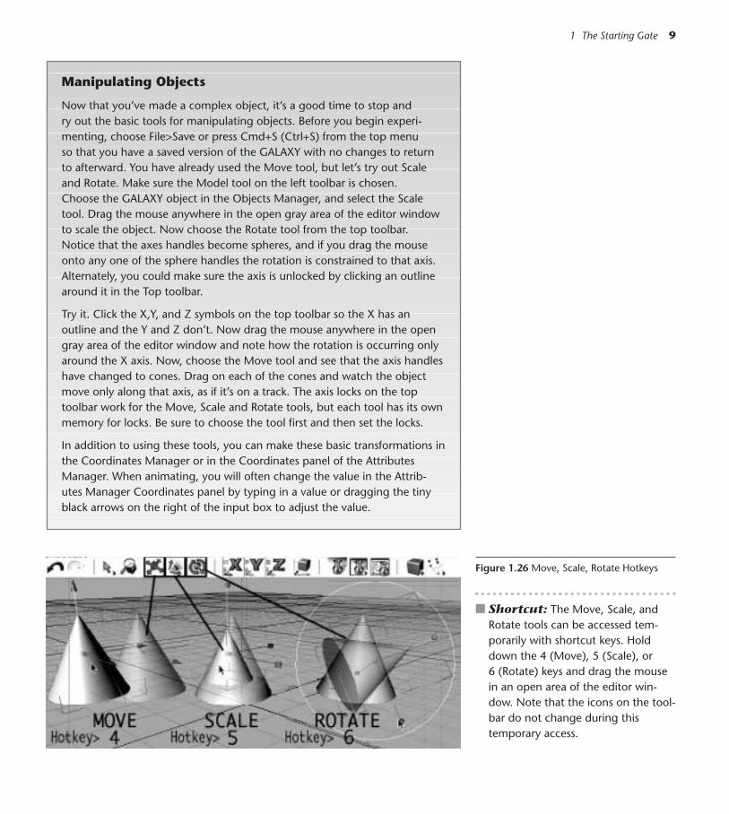
■ Shortcut: The Move, Scale, andRotate tools can be accessed tem-porarily with shortcut keys. Holddown the 4 (Move), 5 (Scale), or6 (Rotate) keys and drag the mousein an open area of the editor win-dow. Note that the icons on the tool-bar do not change during thistemporary access.
1 The Starting Gate 9
Figure 1.26 Move, Scale, Rotate Hotkeys
Manipulating Objects
Now that you’ve made a complex object, it’s a good time to stop and ry out the basic tools for manipulating objects. Before you begin experi-menting, choose File>Save or press Cmd+S (Ctrl+S) from the top menu so that you have a saved version of the GALAXY with no changes to return to afterward. You have already used the Move tool, but let’s try out Scaleand Rotate. Make sure the Model tool on the left toolbar is chosen. Choose the GALAXY object in the Objects Manager, and select the Scaletool. Drag the mouse anywhere in the open gray area of the editor windowto scale the object. Now choose the Rotate tool from the top toolbar. Notice that the axes handles become spheres, and if you drag the mouseonto any one of the sphere handles the rotation is constrained to that axis.Alternately, you could make sure the axis is unlocked by clicking an outlinearound it in the Top toolbar.
Try it. Click the X,Y, and Z symbols on the top toolbar so the X has anoutline and the Y and Z don’t. Now drag the mouse anywhere in the opengray area of the editor window and note how the rotation is occurring onlyaround the X axis. Now, choose the Move tool and see that the axis handleshave changed to cones. Drag on each of the cones and watch the objectmove only along that axis, as if it’s on a track. The axis locks on the top toolbar work for the Move, Scale and Rotate tools, but each tool has its ownmemory for locks. Be sure to choose the tool first and then set the locks.
In addition to using these tools, you can make these basic transformations inthe Coordinates Manager or in the Coordinates panel of the AttributesManager. When animating, you will often change the value in the Attrib-utes Manager Coordinates panel by typing in a value or dragging the tinyblack arrows on the right of the input box to adjust the value.

Figure 1.29 Letters R.H, R.P and R.B
10 CINEMA 4D
Figure 1.30 Sliding to Animation>AddKeyframe
Figure 1.27 Object Tool
Figure 1.28 Current Time 0
Step 4 In the Attributes Manager, click on the Coordinates panel. Command-click (Right-click) on any of the letters R (R.H, R.P, R.B; for RotationHeading, Rotation Pitch, and Rotation Bank, respectively) in the right-hand column and drag to Animation>Add Keyframe. Hold down themouse as you slide sideways, moving across one menu list to the next.
Spin the Galaxy!
Step 1 From the top menu, choose File>Revert to Saved and click Yes on theDialog Box for Lose Changes. Select the GALAXY object in the ObjectsManager.
Step 2 From the lefthand toolbar, choose the Object tool, which should alwaysbe active when animating.
Step 3 Make sure the current time on the Animation toolbar is at 0 frames.
Figure 1.33 Rotation Animation Enabled
Step 5 Click on Go to End of Animation on the Animation Toolbar.
Step 6 In the input box next to R.H (Rotation Heading) in the Coordinatespanel of the Attributes Manager, enter 360 and press Return (Enter).Command-click on the letter H (in R.H) and drag to Animation>AddKeyframe.
You only keyframed the H, or Heading Rotation value. Had you clicked anyof the letters R and set a keyframe, all values (Heading, Pitch, and Bank) wouldhave been keyframed at once.
■ Shortcuts: Pressing the F9 key is a shortcut for keyframing selected values,but the specific kind of animation must be enabled in the Animation toolbar.The F8 key plays an animation. (Note: certain systems may have functionsalready assigned to these keys, so if these shortcuts don’t work you’ll have todecide priorities for your F-keys and reassign functions if desired.)
Step 7 Drag the current time slider to 20 frames and enter 20 in the input boxnext to R.P (Rotation Pitch). Press Return (Enter). Set a keyframe byCommand-clicking on the P in R.P and sliding over to Animation>AddKeyframe. (If you have a multiple button mouse on a PC or Mac, click-ing the right mousebutton is the equivalent of Command-clicking.) Atframe 90 enter a value of 0 in the input box for R.P and set a keyframe.
Step 8 Click the Play button on the Animation toolbar or use the shortcut, F8.
Now you are an animator!
The Barometer ConeMaking the Model
Step 1 Choose File>New to open a new scene and select Display>Wireframefrom the menu immediately over the editor window. Save the file asBarometer Cone in your Models folder (File>Save; Cmd+S/Ctrl+S).
Step 2 Choose Primitive>Add Cone Object. In the Attributes Manager click theObject panel to access Object Properties. Enter a value of 300 for Heightand choose –Y in the Orientation pulldown menu.
Step 3 Control-drag a copy of the Cone in the Objects Manager, and renamethe copy Mercury.
Step 4 With Mercury still selected, click the Attributes Manager Coordinatespanel and enter a value of 0.7 in the input boxes next to S.X, S.Y, andS.Z to scale the Mercury to 70 percent. Press Return (Enter).
1 The Starting Gate 11
Figure 1.34 20 Frames
Figure 1.35 20 Degrees Pitch
Figure 1.31 End of Animation
Figure 1.32 360 degrees H (Heading)

Step 5 Choose Primitive>Torus. (Now that you’re experienced in choosingPrimitives, we’ll just say Torus and drop those extra words.) In the At-tributes Manager Coordinates panel enter 0.1 into the input boxesnext to S.X, S.Y, and S.Z. Click on the Slice panel, and check the Slicecheck box.
Step 6 Click the Object panel and choose –Z from the Orientation pulldownmenu. Double-click the object Torus and rename it Hanger.
Step 7 With Hanger still selected, drag the green handle of the Move tool up-ward until the Hanger rests on top of the cone. (Make sure the Modeltool is selected, since you are modeling.) A maneuver like this shouldbe done in an orthographic view, like Front, so you can see precisely ifthe hanger is resting on top of the cone.
Step 8 Click in the open gray area of the Objects manager, (a good habit tomake sure that Manager is the active one), select all (Edit>Select All,Cmd+A/Ctrl+A) and press the G key to Group. Rename the group NullObject as Barometer Cone.
Materials for the Cone
Step 1 In the Materials Manager, choose File>BhodiNUT Volume>BhodiNUTBanji. Double-click the material thumbnail. In the SLA Editor, choosethe Transparency parameter and reduce the Index of Refraction to 1.1.From the menu over the Objects Manager, choose Unfold All. Place theBanji material on the Cone and Hanger inside the Barometer Cone hi-erarchy.8.5 Update Choose File>Shader>Banji. Double-click the material thumb-nail. Edit Transparency in the Material Editor rather than the SLA Editor.
Step 2 In the Materials Manager, choose File>BhodiNUT Volume>BhodiNUTCheen. In the SLA Editor, choose the Roughness parameter. ChooseCell Voronoi as the Bump Function. Place the Cheen material on theMercury. Type Control-R for a test rendering of the Editor Window,then click the window to clear the rendering.8.5 Update Choose File>Shader>Cheen. Double-click the materialthumbnail. Edit Roughness in the Material Editor.
Color Drops
Creating the Model
Step 1 Choose File>Open and navigate to Chapter 01>C4D Files>Color Drops.c4d on the DVD. Choose File>Save As and save the file as Color Dropsinto your Models folder.
Figure 1.37 Barometer Cone
12 CINEMA 4D
Figure 1.36 A Cone in a Cone

Figure 1.38 Color Drops
Step 2 Choose Primitive>Sphere. In the Attributes Manager under ObjectProperties, enter a Radius of 5 and Segments of 50.
Step 3 With the Sphere still selected, choose Functions>Duplicate from theTop menu. In the input box for Copies, enter 5 and leave the box forGenerate Instances unchecked.
Under the column for Move, enter a value of 200 for Y. (Don’t pressReturn yet.) Under the column for Scale, enter 4 in the X, Y, and Z Boxes.Click OK or press Return.
Step 4 Rename the resulting Null Object as Color Drops. In the Objects Man-ager, drag the name Sphere and drop it onto the name Color Drops.
1 The Starting Gate 13
Placing the Materials
Place a different jewel color from the Materials Manager on each of the Spheres.You can also drag a material directly to the object in the Editor window.
Animating the Color Drops
Step 1 In the Objects Manager, make sure the hierarchy of Color Drops is open.(Click on the plus sign (+) to the left of the name if it isn’t. If you see theminus sign (–), it is already open.)
Step 2 Select Sphere.4. Choose the Object tool and the Move tool.
Step 3 Make sure that the current time slider in the Animation Toolbar is onframe 0.

◆ Tip: To see whether the spheres are aligned correctly, work in the Front View.
Step 4 Drag the green handle of the Move tool upward until Sphere.4 touchesthe bottom of the top sphere. On the Animation Toolbar, turn onrecording for Position (only) and click the Record button (or press theF9 key).
Step 5 Starting with Sphere.3 and working upward in the hierarchy, moveeach sphere (with the green handle) to touch the one above it andkeyframe the position as you did in Step 4 until all the spheres are key-framed to be touching in Frame 0. Remember to click the Record but-ton after moving each sphere.
Step 6 Move the current time slider to Frame 10. Select the smallest sphere atthe bottom of the stack (Sphere), and in the Attributes Manager Coor-dinates panel, enter a P.Y value of –50 and press Return (Enter). (Youmay need to choose Edit>Frame Scene from the Menu over the View tobe able to see the entire stack.) Press F9 to set a keyframe or click the Re-cord button.
Step 7 To make the spheres drop one at a time, you’ll need to keyframe the“dropped” position of Sphere.1 at 20 frames, Sphere.2 at 35 frames,Sphere.3 at 50 frames, and Sphere.4 at 65 frames. Starting with Sphere.1(at frame 20) and working upward to Sphere.4, manually drop eachsphere down to rest on the one below it, keyframing each position withthe F9 key or Record button. See the example file and finished movieon the DVD.
Step 8 Choose File>Save (or Cmd+S/Ctrl+S) and File>Close.
The Bubbling Teardrop
Composing the Model
Step 1 Choose File>New to open a new scene and select Display>Wireframefrom the menu immediately over the editor window. Save the file in yourModels folder as Bubbling Teardrop by choosing File>Save or Cmd+S(Ctrl+S).
Step 2 Choose Primitive>Cone. Rename the Cone as Teardrop.
Step 3 In the Attributes Manager Object Properties (you may have to click theObject panel), enter a value of 300 for Height and press Return (Enter).Click the Caps panel. Click the check box next to Bottom, enter a valueof 100 for both Radius and Height and press Return (Enter). In the in-put box for Fillet Segments, enter 9.
14 CINEMA 4D
Figure 1.41 Sphere Position at Frame 10
Figure 1.42 Height
Figure 1.43 Caps
Figure 1.39 Position Enabled
Figure 1.40 Record Button

Assigning a Material
Step 1 From the Materials Manager at the bottom left of the screen, chooseFile>BhodiNUT Volume, BhodiNUT Banji. 8.5 Update Choose File>Shader>Banji.
Step 2 Double-click on the material thumbnail that appears in the MaterialsManager and make sure a gray band appears over the word Diffuse inthe Smells Like Almonds editor window. Double-click on the DiffuseColor box at the upper left of the page and choose a turquoise blue.You can use the RGB sliders to adjust the color if you prefer. 8.5 Update Edit the Diffuse color by double-clicking the horizontalrectangle.
Step 3 At the top of the Diffuse page, click on the Volume tab and edit thecolor to be more like a royal blue. 8.5 Update In the bottom panel of the Diffuse page, edit the hori-zontal tab for volume color.
1 The Starting Gate 15
Figure 1.44 Banji
Figure 1.45 SLA Edit

Step 4 On the left side of the Smells Like Almonds editor window, click thepanel for Roughness. Next to Bump Function, choose Turbulence fromthe pulldown menu. Click OK to close the SLA Editor. Place the newmaterial on the Teardrop.8.5 Update Edit Roughness in the Material Editor. Bump Function isnow Function.
Import Some Bubbles
Step 1 Choose File>Merge. Navigate to the Color Drops.c4d file you just finishedand click Open in the dialog box. ( It should be in your Models folder.You could also use the sample file in Chapter 1>EXAMPLES>Color Dropson the DVD.)
Step 2 In the Objects Manager, select Color Drops.
Step 3 In the Attributes Manager, click the Coordinates panel and enter a valueof 180 in the box next to R.B (Rotation Bank). Press Return or clickApply.
Step 4 Still in the Coordinates panel, drag the small black arrows to the rightof the box for P.Y until the largest sphere inside the Color Drops ob-ject is just inside the bottom of the Teardrop.
Step 5 Choose Primitive>Torus. In the Attributes Manager under Object Prop-erties, enter 25m for Ring Radius, 5m for Pipe Radius and choose +Zfrom the Orientation pulldown menu. Rename the Torus as Ring. Placethe material you created for the teardrop on the Ring.
Step 6 Choose the Model tool and Move tool. Drag the green handle of theMove tool in the editor window to move the Ring to the top of theTeardrop.
Step 7 Select Teardrop and Color Drops, and press the G key. Rename the NullObject as Teardrop. Drag the object Teardrop into the object Ring. With
16 CINEMA 4D
Figure 1.46 Volume Tab
Figure 1.47 Roughness
Figure 1.48 Bubbles
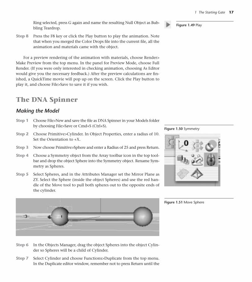
Figure 1.49 PlayRing selected, press G again and name the resulting Null Object as Bub-bling Teardrop.
Step 8 Press the F8 key or click the Play button to play the animation. Notethat when you merged the Color Drops file into the current file, all theanimation and materials came with the object.
For a preview rendering of the animation with materials, choose Render>Make Preview from the top menu. In the panel for Preview Mode, choose FullRender. (If you were only interested in checking animation, choosing As Editorwould give you the necessary feedback.) After the preview calculations are fin-ished, a QuickTime movie will pop up on the screen. Click the Play button toplay it, and choose File>Save to save it if you wish.
The DNA Spinner
Making the Model
Step 1 Choose File>New and save the file as DNA Spinner in your Models folderby choosing File>Save or Cmd+S (Ctrl+S).
Step 2 Choose Primitive>Cylinder. In Object Properties, enter a radius of 10.Set the Orientation to +X.
Step 3 Now choose Primitive>Sphere and enter a Radius of 25 and press Return.
Step 4 Choose a Symmetry object from the Array toolbar icon in the top tool-bar and drop the object Sphere into the Symmetry object. Rename Sym-metry as Spheres.
Step 5 Select Spheres, and in the Attributes Manager set the Mirror Plane asZY. Select the Sphere (inside the object Spheres) and use the red han-dle of the Move tool to pull both spheres out to the opposite ends ofthe cylinder.
1 The Starting Gate 17
Figure 1.50 Symmetry
Figure 1.51 Move Sphere
Step 6 In the Objects Manager, drag the object Spheres into the object Cylin-der so Spheres will be a child of Cylinder.
Step 7 Select Cylinder and choose Functions>Duplicate from the top menu.In the Duplicate editor window, remember not to press Return until the

values are entered in all the boxes. Enter 100 for Copies and check thecheckbox for Generate Instances.
In the Move column, enter 3000m for Y. All Scale values should beleft as 1. Under Rotation, type a value of 360º in the H box and clickOK or press Return. (Choose Edit>Frame Active Object from the menuover the editor window to see the elongated model.)
Step 8 Rename the Null Object as DNA. Drop Cylinder into the DNA object.Select DNA. In the Attributes Manager Coordinates panel, enter a Ro-tation B value of 180º and press Return (Enter). (Now the axis is at thetop so we can animate a swinging action later.) Choose Edit>Frame Ac-tive Objects once again.
Step 9 Choose Primitive>Sphere and give it a Radius of 175m in Object Prop-erties.
Select Sphere and DNA. Press the G key to group them and renamethe Null as DNA Spinner.
18 CINEMA 4D
Figure 1.52 DNA Flipped
Figure 1.53 DNA Spinner
What are Instances?
When you check the check box for Generate Instances in the Duplicate win-dow, you give CINEMA 4D permission to display “ghosts” that refer to anoriginal object. Not only does this save storage space, but also it saves timeand work. Because the referenced duplicates are only additional displaysfrom the data of an original object, any change made to the original willupdate in the instances.
Making the Material
Step 1 In the Materials Manager, choose File>New Material and double-clickthe material thumbnail. In the Material Editor, select the Color param-eter. Click the small black triangle at the right of the Texture panel, andslide over to BhodiNUT Channel>BhodiNUT Gradient.8.5 Update Click on the small black triangle ( now at the left of thetexture panel) and choose Gradient.
Step 2 In the Texture panel, click the Edit button. In the SLA editor window,double-click the lefthand color tab (currently black) at the bottom of thewindow, and edit the color to be a medium green. Click OK. Place thematerial on the DNA object.8.5 Update To edit the Gradient shader, click the word Gradient in thelong middle button.
Step 3 Click on the Browser tab to the right of the Objects Manager tab. ChooseFile>Import File from the Browser menu and navigate to the Chapter 01>EXAMPLES>Galaxy Ball.c4d file. Double-click the thumbnail to open the
1 The Starting Gate 19
The Browser, Your New Best Friend
In the Browser, you can open folders of materials (in their graphics formats) or .c4d files containing materials. Double-clicking a Browser thumbnail opensthe file, and objects or resources can be cut and pasted between currently openfiles. Putting the concept of Browser libraries to work will keep you organizedand save hours of repetitive work.
Spin the DNA
Animate the DNA Spinner to rotate H (heading) 360º in the same way that youanimated the Galaxy Ball in the first project of this chapter.
The Starlight Lantern
Making the Model
Step 1 Choose File>Open and navigate to Chapter 01>C4d Files>StarlightLantern on the DVD. Choose File>Save As and save the file as StarlightLantern in your Models folder.
Step 2 Choose Primitive>Cylinder. Use the top, middle parametric handle toshorten the height to about 150m. (You can keep your eye on thevalue for Y size in the Coordinates Manager while you drag the para-metric handle.)
◆ Tip: If the Parametric handles ever refuse to move or appear, check these“gotchas”: the Model tool and the Move, Scale, or Rotate tool must beselected; the X, Y, Z lock for the attempted direction must be unlocked (an outline is apparent around the letter); and the object must have notalready been made editable.
Figure 1.54 Browser Thumbnails
3D Famous Saying
“If only I could find that model Imade last year.” Take the time tocreate a filing system for storingmodels, materials, splines, andyour other libraries. When youneed an element in a hurry,opening a single folder in thebrowser will give you fast access.
Galaxy Ball file. In the Materials Manager, copy the Gold material withCmd+C (Ctrl+C). Choose the DNA Spinner.c4d file from the Windowmenu. Click on the Materials Manager and paste the Gold materialthumbnail Manager using Cmd-V (Ctrl-V).
Step 4 Click the Objects Manager tab, and place the Gold material on thesphere.
Step 5 Render the Editor Window with Ctrl-R.

Step 3 In the Objects Manager, Control-drag a copy of the cylinder. Renamethe copy as Band. In the Attributes Manager under Object Properties,enter a Height of 10m.
Step 4 From the top toolbar, choose a Symmetry object. Drop the object Bandonto the object Symmetry in the Objects Manager.
Step 5 Select the Symmetry object, and in the Attributes Manager, choose XZfrom the Mirror Plane under Object Properties.
Step 6 Choose the Move tool and select the Band. Slide the green handle up-ward until the bands are neatly capping the top and bottom of thecylinder.
Step 7 Choose Primitive>Torus. In the Attributes Manager, give the Torus aRing Radius of 5m and a Pipe Radius of 2m. Choose +Z from the Ori-entation pulldown menu. Rename the Torus as Hanger.
Step 8 Choose the Move tool, and using the green handle, pull the Torus ringupward to form a hanging ring for the Lantern.
Step 9 In the Objects Manager, rename the Symmetry object as Bands. Holddown the Shift key and select Hanger, Bands, and Cylinder. Press theG key to create a group (Null Object) and rename the group as STAR-LIGHT LANTERN.
Step 10 Drag the object named Lamplight into the STARLIGHT LANTERN Group.
Materials with PunchStep 1 In the Materials Manager, choose File>New Material.
Step 2 Double-click on the material thumbnail and in the Material Editor, se-lect the Color parameter. In the Texture panel of the Color page, movethe mouse to the small black triangle (to the right of the empty box)and drag over to Shader>Checkerboard.8.5 Update From the black triangle (now on the left of the texturepanel) choose Surfaces>Checkerboard. Note: this is where everythingfrom the Shader list in former versions can now be found.
Step 3 In the Attributes Manager, enter 12 in the box for U frequency and 0 inthe box for V frequency. Rename the new material as Stripes (Double-click on the red words Mat.1 at the bottom of the thumbnail) and dragthe material thumbnail onto the name Band in the Objects Manager. 8.5 Update In the Material Editor, click the word Checkerboard in theelongated button to edit the UV frequencies. (Alternately, you can ac-cess all the Shader buttons in the Attributes Manager after selecting achannel.)
Step 4 In the Materials Manager, choose File>New Material.
Step 5 Double-click on the material thumbnail and in the Material Editor, se-lect the Color parameter. Again in the Texture panel of the Color page,
Figure 1.55 Symmetry
20 CINEMA 4D
Figure 1.56 Hanger

Figure 1.57 Starlight Lantern. The lightsalready placed in the file are volumetriclights and will take longer to render. Be-cause the lights will honor the holes in thematerial’s Alpha channel, the computer hasmore calculating to do.
move the mouse to the small black triangle (to the right of the emptybox) and drag over to Shader>Gradient.8.5 Update Click on the small black arrow and drag to Gradient.
Step 6 In the Attributes Manager under Shader Properties, double-click the left-hand color tab and choose a red. Edit the righthand color tab to be pur-ple. Click the bottom of the color band to add a new tab and in the Colorsbox edit its color to be white. Choose 2D-V from the Mode menu.8.5 Update Click the word Gradient in the elongated button to editas in Step 6.
Step 7 Back in the Material Editor, select the Alpha Channel and check itscheck box.
Step 8 Click the small black triangle and drag to Shader>Stars.8.5 Update Drag to Surfaces>Stars.
Step 9 In the Attributes Manager under Shader Properties, enter 5 in the box forStreaks and 5 in the box for Density. 8.5 Update Click the word Stars to edit the shader as in Step 9 above. In the Material Editor, click the word Stars on the elongated button toedit the shader as in Step 9 above.
Step 10 Rename the new material Star Gradient, and drop it onto the STARLIGHTLANTERN object in the Objects Manager. Click on the Texture Tag thatappears in the righthand column. In the Attributes Manager, enter 50%for Length X.
Step 11 Press Ctrl+R to render the editor window.
Twirl the LanternAnimate the Lantern to rotate H (heading) 360º in the same way that you ani-mated the Galaxy Ball in the first Project of this chapter.
The Cosmic Receiver
Creating the Model Step 1 Choose File>New and save the file as Cosmic Receiver in your Models
folder by choosing File>Save or Cmd+S (Ctrl+S).
Step 2 Choose Primitive>Torus.
Step 3 In the Attributes Manager under Object Properties, enter a value of 10for Ring Radius and 1 for Pipe Radius.
Step 4 Choose Functions>Duplicate. Enter 9 in the box for Copies, leave Gen-erate Instances unchecked, and enter 500 in the Y box in the Move col-umn. In the Scale column enter 20 for X, 1 for Y and 20 for Z. Click OK.Choose Edit>Frame Scene to fill the working space with the object.
1 The Starting Gate 21
Figure 1.58 Cosmic Receiver

Step 5 Rename the resulting Null Object as Cosmic Rings.
Step 6 Choose Primitive>Capsule. Use the parametric handles and the greenhandle of the Move tool to adjust the Capsule so it floats comfortablyinside the rings.
Step 7 Select the Torus in the Objects Manager and in the column to the rightof the name, click the top gray dot twice so that it turns red. Now theoriginal Torus is not visible in the editor window. Also click the bottomgray dot twice to keep the Torus from rendering.
Step 8 Select the Torus, Capsule, and Cosmic Rings. Press the G key to groupthem and name the resulting Null Object as Cosmic Receiver.
Add Some Materials and a Light
Step 1 In the Materials Manager, choose File>BhodiNUT Volume>Danel.8.5 Update Choose File>Shader>Danel.
Step 2 In the Smells Like Almonds editor window, change the Diffuse colorto turquoise, Specular 2 to light blue, and Specular 3 to light green.8.5 Update Double-click the Material thumbnail and edit the Diffuseand Specular colors in the Material Editor.
Step 3 In the Materials Manager, choose File>BhodiNUT Volume>Banji.8.5 Update Choose File>Shader>Banji.
Step 4 Place the Danel material on the Cosmic Rings object and the Banji ma-terial on the Capsule.
Step 5 Now for something new—click on the Light toolbar symbol in the toptoolbar.
Step 6 In the Attributes Manager under the General panel, double-click theColor box and choose a pale creamy yellow for the light’s color. ChooseTube from the Type pulldown menu.
Step 7 Select Volumetric from the Visible Light menu.
Step 8 Click the Attributes Manager Coordinates panel and enter 90º in thebox for R.P (Pitch) and press Return (Enter).
Step 9 With the Light still selected, choose Functions>Transfer from the topmenu.
Make sure only Position is checked and type the letters CA (for cap-sule) in the Search For box. Click OK. The light magically jumps to theposition of the Capsule.
Step 10 With the Model and Move tools selected and Light still the active object,drag the orange handles at the outer circles defining the light until theTube fits well inside the Capsule. Leave enough room around the Tubeso that it can be seen clearly in the Capsule.
22 CINEMA 4D
Figure 1.60 Light Icon Frame 10
Figure 1.61 Tube Light
Figure 1.59 Visibility Off
1 The Starting Gate 23
Figure 1.62 Randomize Box
Figure 1.64 Cosmic Final
Figure 1.63 H Keyframe
Navigating the 3D World
The icons on the top right of each view window allow you to navigate the editor camera in the 3D space. You’llprobably prefer using these keyboard hotkeys. Mac Users:Hold down the appropriate key as you drag the mouse.The 1 key “tracks” or moves the view side to side or upand down. The 2 key moves the camera in and out. If youwant to zoom the camera rather than move it (becausezooming changes its focal length and distorts perspec-tive), use Cmd+the 2 key (right-click). The 3 key rotates or tumbles the view. (Cmd+3 performs a Dutch tilt. Try itto see what it looks like!) Cmd-Shift-Z and Cmd-Shift-Yundo and redo views.
Windows Users: The 1 key + Left Mousebutton movesthe view side to side or up and down. The 2 key + the leftMousebutton moves the camera in and out. The 2 key +Right Mousebutton Zooms the camera. The 3 key + theLeft Mousebutton rotates or tumbles the view (add theCommand key to that for a Dutch Tilt). (Ctrl-Shift-Z) and(Ctrl-Shift-Y) undo and redo views.
Figure 1.65 View Icons
Figure 1.66 View Hotkeys
Animate the Rings
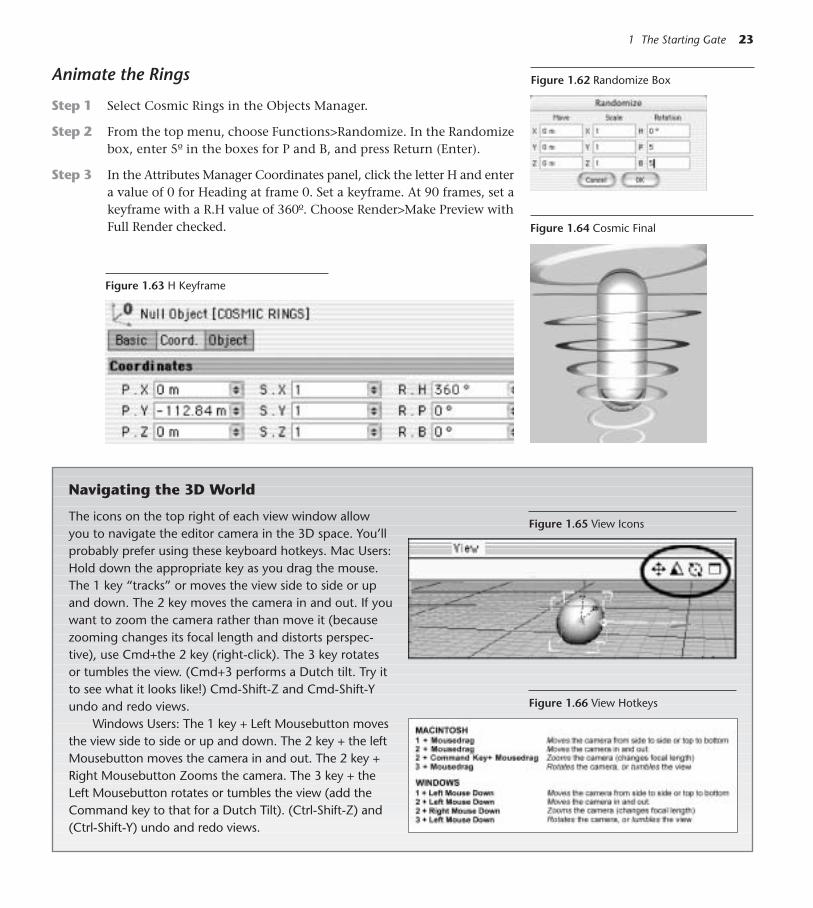
Step 1 Select Cosmic Rings in the Objects Manager.
Step 2 From the top menu, choose Functions>Randomize. In the Randomizebox, enter 5º in the boxes for P and B, and press Return (Enter).
Step 3 In the Attributes Manager Coordinates panel, click the letter H and entera value of 0 for Heading at frame 0. Set a keyframe. At 90 frames, set akeyframe with a R.H value of 360º. Choose Render>Make Preview withFull Render checked.

Pandora’s Box
Making the Model
Step 1 Choose File>New and save the file as Pandora’s Box in your Models folderby choosing File>Save or Cmd+S (Ctrl+S).
Step 2 Choose Primitive>Cube. In Object Properties, enter 150 for Size Y.Check the check box for Fillet, and enter 3 for both Fillet Radius andSubdivision.
Step 3 Choose the Front view by pressing the F4 key or choosing View>View 4.In the Objects Manager, Control-drag a copy of the original cube and re-name it Band. In Object Properties, enter 40 for Size.Y.
Step 4 Choose a Symmetry object from the top toolbar, and set the Mirror Planeto be XZ. Drop the object Band onto the Symmetry object.
Step 5 Select the Band object. Use the green handle of the Move tool to po-sition the mirrored Bands at the top and bottom of the original cube.
Step 6 Rename the Symmetry object as Bands. Choose File>Save or press Cmd+S(Ctrl+S).
Create a Decorative Lock
Step 1 Choose File>New. (Leave the Pandora’s Box file open.)
Step 2 Choose Primitive>Torus. In Object Properties, give the Torus an ori-entation of –X. Click the Slice panel and check the check box for Slice.
Step 3 From the top toolbar, choose Functions>Duplicate. Enter 12 for Copies.In the Move column, enter 500 in the box for Y. (All Scale values shouldremain at 1, and all other values should be 0.) Under Rotation, type 180for the B (bank) value. Press Return (Enter).
24 CINEMA 4D
Figure 1.67 Symmetry
Figure 1.68 Box and Bands
Figure 1.69 Lock Detail

Step 4 Rename the resulting Null Object as Lock Detail. Drag the original Torusinto the Lock Detail. Select the Lock Detail object, then type Cmd+C(Ctrl+C) to copy it. Choose File>Close from the top menu to close theLock Detail File. You may want to save it for future use in your modelsfolder.
Step 5 In the Pandora’s Box file, type Cmd+V (Ctrl+V) to paste the Lock De-tail into the scene.
Step 6 Make sure the Model tool is selected in the left toolbar. Rotate the LockDetail to the proper orientation by entering 180 for R.H and –90 forR.B in the Attributes Manager Coordinates panel. Working in All Views(F5), use the Move and Scale tools to manually size and position thelock on the box.
Choosing Materials
Step 1 Choose File>New Material from the Materials Manager menu. Double-click the new material thumbnail and in the Material Editor, select theColor parameter.
Step 2 In the Texture panel of the Color page, click the small black triangle andslide over to Shader>Checkerboard. In the Attributes Manager, enter 10for U Frequency and 8 for V Frequency. Place the Checkerboard mate-rial on the Cube object.8.5 Update Choose Surfaces>Checkerboard and click the word Check-erboard to edit the shader as in Step 2, above.
Step 3 Click the Browser tab (to the Right of the Objects Manager tab). ChooseFile>Import File and navigate to the Chapter 1>EXAMPLES>GalaxyBall.c4d file. Double-click the Galaxy Ball thumbnail and Shift-click toselect the Gold material and a purple material. Press Cmd+C (Ctrl+C) tocopy the materials. Return to the Pandora’s Box file via the Windowmenu list.
Step 4 Click the Materials Manager to assure that it is the active window, andpaste the materials with Cmd+V (Ctrl+V). Click the Objects Managertab. Place the Gold material on the Lock Detail, and the purple mate-rial on the Bands symmetry object.
Easy and Breezy
Choosing the Models
Step 1 Choose File>New and save the file as Easy and Breezy in your Modelsfolder by choosing File>Save or pressing Cmd+S (Ctrl+S).
1 The Starting Gate 25
Figure 1.70 Lock on Box
Figure 1.71 Pandora’s Box

Step 2 Choose Primitive>Platonic. In the Attributes Manager Object Proper-ties, choose Icosa from the Type pulldown menu. Rename the Platonicas Surface.
Step 3 Control-drag a copy of Surface and rename it Frame Icosa.
Step 4 Choose an Atom Array from the Top toolbar (under the Array toolbaricon.)
Step 5 Drop the object Frame Icosa onto the object Atom Array, and renamethe Atom Array as Frame.
Step 6 Select Frame, and in the Attributes Manager enter 2m for Cylinder Ra-dius, 10m for Sphere Radius, and 15 for Subdivisions.
Step 7 Select Frame and Surface. Press the G key and rename the resulting Nullobject as Easy and Breezy.
Time for Materials
Step 1 Open the Browser and choose File>Import File. Navigate to Chapter 01>EXAMPLES>Galaxy Ball.c4d.
Step 2 Double-click the thumbnail for Galaxy Ball.
Step 3 Copy the Gold and any color material that you wish using Cmd-C(Ctrl-C). Choose File>Close. Click No when asked to save changes.
Step 4 Return to the Easy and Breezy file, and paste the materials into the Ma-terials Manager with Cmd+V (Ctrl+V).
Step 5 Place the Gold material on the Frame object.
26 CINEMA 4D
Figure 1.72 Atom Array
Figure 1.73 Easy
Figure 1.74 Material Edit

1 The Starting Gate 27
Figure 1.75 Tile Edit
Figure 1.76 Inverted and Not Inverted
A Touch of Animation
Step 1 Set the current time to 0 frames.
Step 2 In the Objects Manager, select the Frame object. In the Attributes Man-ager Object Properties, Command-click (right-click if you have a two-but-ton mouse) on the words Sphere Radius, and slide to Animation>AddKeyframe. A red dot will signal that a keyframe has been set.
Step 3 Forward the time slider to 60 frames.
Step 4 Enter 15 for Sphere Radius and press Return (Enter). Set a keyframe.
Step 5 At 90 frames, set a keyframe with the original Sphere Radius of 10.
Step 6 Click the Play button (or press F8) and watch the model “breathe.”
Figure 1.77 Radius Keyframe
Step 6 In the Materials Manager, double-click the second material thumbnail.Choose the Alpha parameter and check its check box. In the Texturepanel, click the small black triangle and slide down to BhodiNUT Chan-nel>BhodiNUT Tiles.8.5 Update Slide down to Surfaces>Tiles (rather than BhodiNUT Chan-nel>BhodiNUT Tiles)
Step 7 In the Texture panel, click the Edit button. In the Smells Like Almondseditor window, drag on the pulldown menu in the lower left panel(Squares is the default) to select Circles 1. 8.5 Update In the Material Editor, click the word Tiles in the elon-gated button to edit the shader as in Steps 7 and 8.
Step 8 At the top of the SLA window, double-click Tile Color 1 and changeit to black. Change Tile Color 2 to white. In the lower right panel, in-crease Global Scale to 150 percent and press Return (Enter). Name thematerial you just created Polka Dot and place it on the Surface Object.Render the Editor window with Ctrl-R.
Step 9 Double-click the Polka Dot material icon and click on the Alpha pa-rameter pane. Check the checkbox next to Invert and render the Edi-tor again.

The Gyro
Constructing the Gyro
Step 1 Choose File>New and save the file as Gyro in your Models folder bychoosing File>Save or pressing Cmd+S (Ctrl+S).
Step 2 Choose Primitive>Torus. In Object Properties, enter 150m for Ring Ra-dius and 10 for Pipe Radius. Set the Orientation to +X. Increase the RingSegments to 50.
Step 3 Choose Functions>Duplicate. Enter 1 for Copies, 0 for all Move values,and 90º for B Rotation. Click OK. In the Objects Manager, type Cmd+A(Ctrl+A) to select all, then press the G key to group. Rename the result-ing Null Object as Outer Frame.
28 CINEMA 4D
Figure 1.78 Outer Frame Figure 1.79 Spinners
Figure 1.80 Gyro Hanger
Step 4 With Outer Frame selected, choose Functions>Duplicate again. UnderRotation, enter 0 for H and 50 for both P and B. Rename the new NullObject as Inner Frame.
Step 5 In the Attributes Manager Coordinates panel, enter 0.89 in the S.X, S.Y,and S.Z boxes.
Step 6 Shift-click to select Outer Frame and Inner Frame, and type G. Namethe Null Object as Spinners.
Step 7 Choose Primitive>Sphere and in Object Properties, increase the seg-ments to 40. Control-drag a copy of the Sphere. Scale one Sphere tofloat just outside the Spinners and leave the other to be a smaller coresphere inside the Spinners. Title the Outer Sphere and Inner Sphere.
Step 8 Choose Primitive>Cylinder and Primitive>Torus. Using parametric han-dles and the Move, Rotate, and Scale tools, craft a hanger with these

primitives. Group the Cylinder and Torus by pressing the G key, renamethe group as Hanger, and place it at the top of the outer Sphere.
Step 9 In the Objects Manager, select the Spinners, Outer Spheres, and InnerSphere and press the G key to Group. Rename the group Gyro.
Step 10 So the whole object will rotate from the Hanger, drop the name Gyro (asthe child) onto the name Hanger (the parent). With Hanger selected,press the G key again and rename the new Null Object GYRO.
The Well Dressed Gyro
Step 1 In the Materials Manager, choose File>BhodiNUT Volume>Banji. Dou-ble-click the material thumbnail, and in the SLA editor window, selectthe Transparency page. Set the Refraction value to 1 and place the ma-terial on the Outer Sphere. 8.5 Update Choose File>Shader>Banji, double-click the thumbnail andedit the Transparency in the Material Editor.
Step 2 Now choose File>BhodiNUT Volume>Nukei. Double-click the materialname and rename it as Turquoise. Place the material on the Inner Sphere. 8.5 Update Choose File>Shader>Nukei.
Step 3 In the Materials Manager, Control-drag a copy of the Turquoise ma-terial thumbnail. Rename the copy Silver Blue. Double-click the ma-terial thumbnail and in the SLA editor window, select the Diffuse page.Edit the color to be a light blue and click OK. Place the Silver Blue ma-terial on the Torus, Cylinder, and Spinners.
The Firefly Lantern
Building the Lantern Frame
Step 1 Choose File>New and save the file as Firefly Lantern in your Modelsfolder by choosing File>Save or pressing Cmd+S (Ctrl+S).
Step 2 Choose Primitive>Cylinder. In Object Properties, enter 8 for RotationSegments.
Step 3 Control-drag a copy of the Cylinder. Rename the original Cylinder asFrame and the copy as Paper.
Step 4 Choose an Atom Array from the Array toolbar icon in the top toolbar.Drop the object Frame onto the object Atom Array. Rename the AtomArray as Lantern Frame.
Step 5 In the Attributes Manager Object Properties, edit the Atom Array tohave a Cylinder Radius and Sphere Radius of 1.
1 The Starting Gate 29
Figure 1.81 Refraction
Figure 1.82 Finished Gyro
Figure 1.83 Atom Array
Figure 1.84 Atom Array Object Properties

30 CINEMA 4D
Figure 1.85 Paper SLA Material
Figure 1.86 Light Position
Figure 1.87 Visibility Settings
Step 6 Click on the Objects Manager, Select all with Cmd+A/(Ctrl+A) andpress the G key to group the Lantern Frame and Paper objects. Renamethe resulting Null Object as FIREFLY LANTERN.
Add Materials and Lights
Step 1 In the Materials Manager, choose File>New Material. Select the Color pa-rameter in the Material Editor. Edit the color to be Khaki, a medium tan.
Step 2 Select and check the Transparency parameter; click the small black tri-angle in the Texture panel and slide to Shader>BhodiNUT Channel>BhodiNUT 3D Noise. Click Edit. In the SLA editor window, choose Zadafrom the Noise menu. In the Scale panel, reduce the Global Scale to 50percent but increase the Y scale to 250. Click OK. Name this materialPaper and place it on the Paper object in the Objects Manager.8.5 Update After clicking the black triangle, slide to Noise rather thanBhodiNUT Channel>BhodiNUT 3D Noise. Click the word Noise to editthe shader as in Step 2. There is no Scale panel, but you’ll see GlobalScale.
Step 3 In the Materials Manager, choose File>BhodiNUT Volume>BhodiNUT >Banzi. In the SLA editor window, change the left color tab on the Woodpage so that it is medium tan. Place this material on the Lantern Frame.8.5 Update Choose File>Shader>Banzi. Double-click the thumbnail andedit the shader in the Material Editor as in Step 3.
Step 4 Click on the Lighting toolbar icon to create a default Omni light. Usethe green handle of the Move tool to slide the light to the bottom ofthe lantern.
Step 5 With the Light still selected, click the General tab in the Attributes Man-ager. Set the Visible Light to Visible. Click the Visibility tab, set the OuterDistance to 20 and press Return. Rename the Light as Firefly 1.

Step 6 Click the Light toolbar icon one more time to create a light to illuminatethe outside of the lantern. Name the light Main and in Attributes man-ager Coordinates, give it Position values of 150 X, 50 Y, and –175 Z.
Animate the Fireflies Using F-Curves
Step 1 To make the animation longer, choose Edit>Project Settings from thetop menu. Enter 200 in the box for Maximum, press Return (Enter) andclose the window.
Step 2 Select Firefly 1 and click the Coordinates panel in the Attributes Man-ager. At frame 0, set a keyframe for the current Position Y on the floorof the lantern. At frame 100, drag the upper small arrow next to P.Yuntil Firefly reaches the top of the Lantern and set a keyframe. Go tothe end of the Animation, move Firefly 1 back to the Lantern floor andset a final keyframe.
Step 3 In the Objects Manager, Control-drag two copies of Firefly 1. Renamethem as Firefly 2 and Firefly 3. Shift-click to select all the Fireflies anddrag them into the name Firefly Lantern.
Step 4 Working in the Top view, move the camera in for a close view (press the2 key and drag the mouse left to right) and use the X and Z Move han-dles to position the Fireflies in a triangle on the floor of the Lantern. Re-turn to the Perspective view.
Step 5 Choose the Animation Layout from the Layout icon at the top of theleft toolbar.
1 The Starting Gate 31
Figure 1.88 Fireflies from Top
Figure 1.89 Animation Layout
Figure 1.90 F-Curve Tab
Figure 1.91 All Graphs
Step 6 On the bottom left of the screen, click the F-Curve Tab.
Step 7 In the Objects Manager, Shift-click to select all the Fireflies. (Alternately,you can drag a selection rectangle over all the names.)
Step 8 In the F-Curve window, you now see all the Firefly names in red and agraph. Choose View>Frame All from the menu over the F-Curve window.

You are looking at the graphs for all the fireflies at once, although theyare aligned on top of each other and appear to be only one.
Step 9 In the F-Curve graph window, click on the green key on the top of thecurve at frame 100. Move it left to frame 30 and lower it to a value of40 on the graph. Choose the next green key (at frame 100), move it toFrame 130 and lower it to a value of 50. The value of 50 on the Y graphis how high the firefly is jumping. Leave the last high point keyframeat frame 100 where it was. Play the Animation by pressing the Play but-ton on the Animation Timeline or press the F8 key.
32 CINEMA 4D
Figure 1.92 All Graphs, Edited. Ah ha! By moving the keys on the graph, you caneasily control how high and when the fire-flies jump. Want to add more bounces? By Control-clicking onthe graph line, newkeys can be added andpositioned at 0 on theY graph. Later, you’lllearn much more aboutusing these powerfulcurves to control thenuances of motion.
The Color Barrel
Constructing the Model
Step 1 Choose File>New and save the file as Color Barrel in your Models folderby choosing File>Save or pressing Cmd+S (Ctrl+S).
Step 2 Choose Primitive>Cylinder. In Object Properties, enter 20 for Heightand +X for Orientation.
Step 3 With Cylinder still selected, choose Functions>Duplicate. Enter 8 forCopies, leave Generate Instances unchecked, and enter 170 for the Xvalue (Y and Z should be 0) in the Move column. (All Scale values shouldbe 1, and all other values 0.) Click OK. Rename the Null Object as ColorBands.
Step 4 With Color Bands selected, choose Functions>Randomize. In the Ran-domize window, enter 180º in the box for P Rotation. Click OK. Dropthe original Cylinder into Color Bands.
Step 5 Click the (+) to the left of Color Bands to open the hierarchy. Shift-clickto select Cylinder and Cylinder.8 (the two end cylinders). By selectingthem together, a value can be edited for both at once.
In Object Properties, enter a Height of 3m. Choose the Scale tooland the Model tool, and drag in the gray area of the window from rightto left so that the end cylinders move closer to the inner seven. Withthe two cap cylinders still selected, enter 50 for Radius.
Figure 1.93 P Randomized

1 The Starting Gate 33
Figure 1.94 Cap Cylinders Shift Selected
Figure 1.95 End Cylinders Moved Closer
Figure 1.96 Radius ofCaps Adjusted
Step 6 Click the Browser tab, and choose File>Import File. Navigate to theChapter 01>EXAMPLES>Gyro.c4d file, and double-click the thumbnailto open the file. Click the Objects Manager tab, and choose Unfold Allfrom the Objects Manager menu.
Step 7 Shift-select Torus and Tube, and copy them with Cmd+C (Ctrl+C). Re-turn to the Color Barrel file via the Window menu, click on the Ob-jects Manager, and paste the objects with Cmd+V (Ctrl+V).
Step 8 With Torus and Tube still selected, press the G key and name the Null Ob-ject as Hanger. Make sure Hanger is selected. Choose Functions>Trans-fer from the top menu and type Cylinder.4 into the Search For box.

34 CINEMA 4D
Figure 1.97 Hanger Position
Figure 1.98 Texture Tags
Figure 1.99 Random Y Tiles
Step 9 Working in All Views (F5) and Isoparm Display, use the Scale tool to makethe hanger small enough to fit inside the top of the middle color band,Cylinder.4. Using the Move tool, move the hanger into position at thetop of the barrel. Make the Color Bands object a child of the Hanger.
Placing Materials
Step 1 In the Materials Manager, choose File>New Material and Control-draga copy of the new material thumbnail.
Step 2 Double-click the name of the first Materials icon and rename it ColorSwatches. Double-click the new material thumbnail and select theColor parameter. In the Texture panel, click the button for Image. Nav-igate to the GOODIES>MATERIALS>ImageMaps folder on the DVDand open the file Color Swatch1.psd.8.5 Update The button to navigate to an image is now the tiny but-ton with three small dots, on the far right.
Click Yes in the box that appears asking if you want to create a copyof the Image. The name of the image file will appear in the Image box.Place the material on each of the seven inner color bands.
Step 3 Shift-click to select the Texture tags for all the Cylinders (.1 through .7).In the Attributes Manager Tag Properties, choose Cylindrical from theProjection pulldown menu.
Step 4 Select the Texture Tag for Cylinder.1. Enter 5 in the box for Tiles Y.
Step 5 Repeat Step 4 for each of the cylinders through Cylinder. 7, but varythe Tile Y value for each cylinder so there are interesting and randomdifferences in the height of the stripes. Make sure the View Display isGouraud. Drag the small black arrows next to Tiles Y so you can seethe stripes change in real time.
Step 6 Double-click the name of the second material thumbnail and renameit Glitter Star. Double-click the new material thumbnail and select theColor parameter. In the Texture panel, click the button for Image.
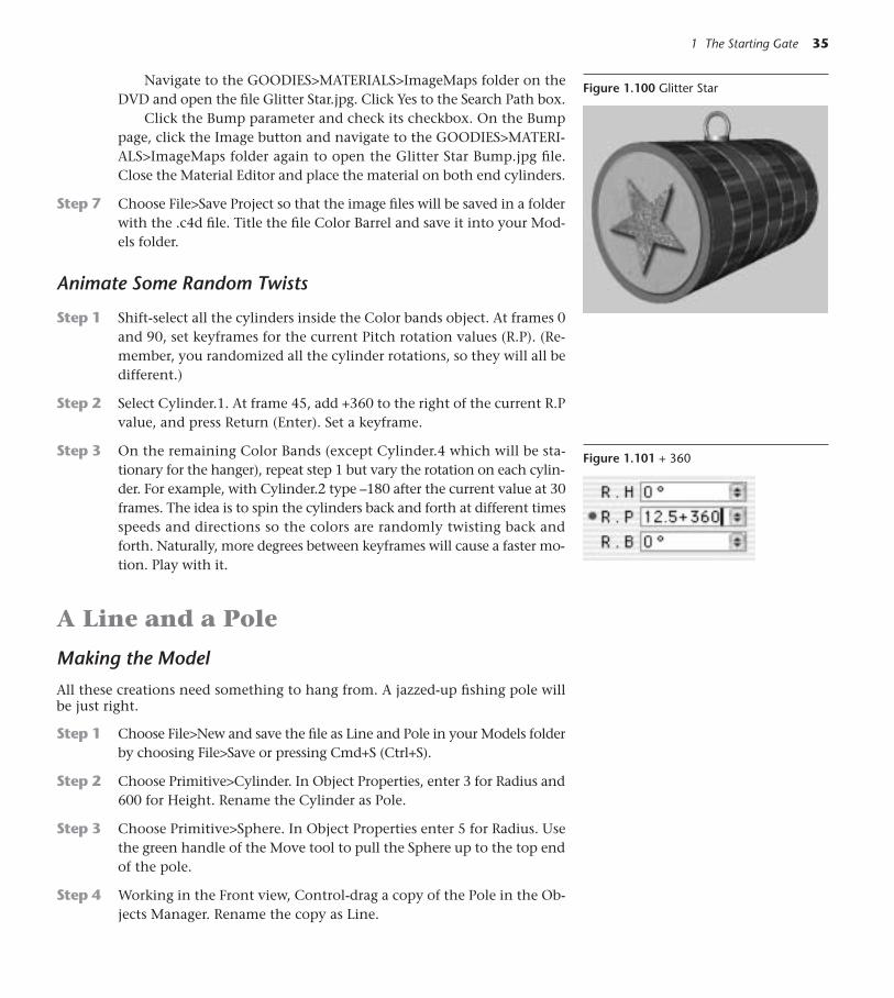
Navigate to the GOODIES>MATERIALS>ImageMaps folder on theDVD and open the file Glitter Star.jpg. Click Yes to the Search Path box.
Click the Bump parameter and check its checkbox. On the Bumppage, click the Image button and navigate to the GOODIES>MATERI-ALS>ImageMaps folder again to open the Glitter Star Bump.jpg file.Close the Material Editor and place the material on both end cylinders.
Step 7 Choose File>Save Project so that the image files will be saved in a folderwith the .c4d file. Title the file Color Barrel and save it into your Mod-els folder.
Animate Some Random Twists
Step 1 Shift-select all the cylinders inside the Color bands object. At frames 0and 90, set keyframes for the current Pitch rotation values (R.P). (Re-member, you randomized all the cylinder rotations, so they will all bedifferent.)
Step 2 Select Cylinder.1. At frame 45, add +360 to the right of the current R.Pvalue, and press Return (Enter). Set a keyframe.
Step 3 On the remaining Color Bands (except Cylinder.4 which will be sta-tionary for the hanger), repeat step 1 but vary the rotation on each cylin-der. For example, with Cylinder.2 type –180 after the current value at 30frames. The idea is to spin the cylinders back and forth at different timesspeeds and directions so the colors are randomly twisting back andforth. Naturally, more degrees between keyframes will cause a faster mo-tion. Play with it.
A Line and a Pole
Making the Model
All these creations need something to hang from. A jazzed-up fishing pole willbe just right.
Step 1 Choose File>New and save the file as Line and Pole in your Models folderby choosing File>Save or pressing Cmd+S (Ctrl+S).
Step 2 Choose Primitive>Cylinder. In Object Properties, enter 3 for Radius and600 for Height. Rename the Cylinder as Pole.
Step 3 Choose Primitive>Sphere. In Object Properties enter 5 for Radius. Usethe green handle of the Move tool to pull the Sphere up to the top endof the pole.
Step 4 Working in the Front view, Control-drag a copy of the Pole in the Ob-jects Manager. Rename the copy as Line.
1 The Starting Gate 35
Figure 1.100 Glitter Star
Figure 1.101 + 360
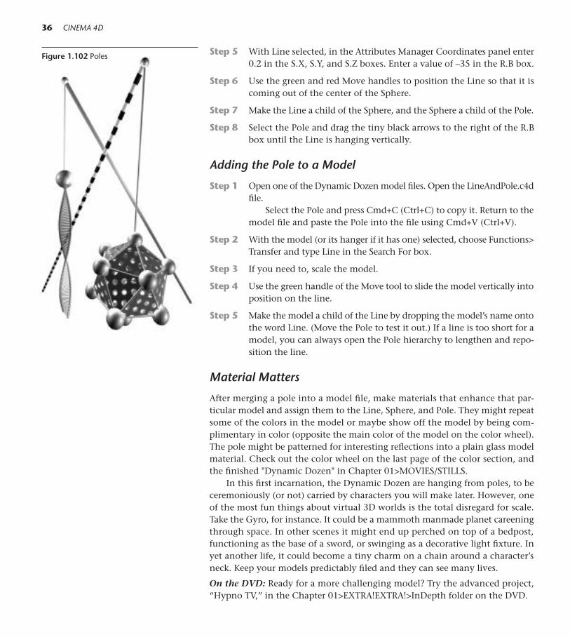
Step 5 With Line selected, in the Attributes Manager Coordinates panel enter0.2 in the S.X, S.Y, and S.Z boxes. Enter a value of –35 in the R.B box.
Step 6 Use the green and red Move handles to position the Line so that it iscoming out of the center of the Sphere.
Step 7 Make the Line a child of the Sphere, and the Sphere a child of the Pole.
Step 8 Select the Pole and drag the tiny black arrows to the right of the R.Bbox until the Line is hanging vertically.
Adding the Pole to a Model
Step 1 Open one of the Dynamic Dozen model files. Open the LineAndPole.c4dfile.
Select the Pole and press Cmd+C (Ctrl+C) to copy it. Return to themodel file and paste the Pole into the file using Cmd+V (Ctrl+V).
Step 2 With the model (or its hanger if it has one) selected, choose Functions>Transfer and type Line in the Search For box.
Step 3 If you need to, scale the model.
Step 4 Use the green handle of the Move tool to slide the model vertically intoposition on the line.
Step 5 Make the model a child of the Line by dropping the model’s name ontothe word Line. (Move the Pole to test it out.) If a line is too short for amodel, you can always open the Pole hierarchy to lengthen and repo-sition the line.
Material Matters
After merging a pole into a model file, make materials that enhance that par-ticular model and assign them to the Line, Sphere, and Pole. They might repeatsome of the colors in the model or maybe show off the model by being com-plimentary in color (opposite the main color of the model on the color wheel).The pole might be patterned for interesting reflections into a plain glass modelmaterial. Check out the color wheel on the last page of the color section, andthe finished "Dynamic Dozen" in Chapter 01>MOVIES/STILLS.
In this first incarnation, the Dynamic Dozen are hanging from poles, to beceremoniously (or not) carried by characters you will make later. However, oneof the most fun things about virtual 3D worlds is the total disregard for scale.Take the Gyro, for instance. It could be a mammoth manmade planet careeningthrough space. In other scenes it might end up perched on top of a bedpost,functioning as the base of a sword, or swinging as a decorative light fixture. Inyet another life, it could become a tiny charm on a chain around a character’sneck. Keep your models predictably filed and they can see many lives.
On the DVD: Ready for a more challenging model? Try the advanced project,“Hypno TV,” in the Chapter 01>EXTRA!EXTRA!>InDepth folder on the DVD.
36 CINEMA 4D
Figure 1.102 Poles
Mechanics 101
I f your goal is to become an unlimited 3D artist with the power to make any-thing, don’t even think about skipping this chapter. Here, you’ll build the skillset to supercharge your artistic vision. While this behind-the-scenes work isn’t
the most stimulating part of your 3D workflow, the ability to create, edit, and re-pair the fundamental elements in CINEMA 4D is critical. The time you spend be-coming proficient at these tasks will yield a big payoff. So roll up your sleeves andlet’s get to work!
2Under the Hood
37
Figure 2.1
Making Primitives Editable
A parametric primitive may be easily converted into a polygonal surface formore complex or organic restructuring. The polygonal surface is made up of interconnected polygons that are quadrilateral or triangular planes de-fined by points or vertices. Adjoining polygons share an edge. The surface,or mesh, may be pushed and pulled into virtually any form by manipula-ting the polygons themselves, the edges connecting them, or the definingpoints. CINEMA 4D has a wealth of tools which will give you the power totransform the surface far beyond its primitive beginnings.

■ Shortcut: Make Editable To make a primitive editable, click the MakeEditable icon on the left toolbar or press the C key. Multiple objects may beselected by Shift-clicking and made editable at once.
38 CINEMA 4D
Figure 2.2 Make Editable
Tools for Editing Surfaces
On the left toolbar, three tools give you access to the elements on the polygo-nal surface. When you want to push and pull points, choose the Points tool.For working with edges, click the Edge tool, and if it’s polygons you want tomanipulate, select the Polygons tool. Although you have a sophisticated set ofselection tools for selecting all these elements, you can also select single ormultiple points, edges, and polygons using the Move, Scale, and Rotate tools.The points, edges, or polys of an editable surface may be transformed singly orin groups selected by Shift-clicking with the same Move, Scale, and Rotatetools you used with primitive objects in Chapter 1. You need to click on theelement first to select it before attempting to Move, Scale, or Rotate.
A Petunia
Step 1 Navigate to the folder Chapter 02>C4D Files and open Petunia.c4d.Choose File>Save As and save it in your Models folder.
Step 2 Choose Primitive>Disc. Press the C key to make the Disc editable.
Step 3 Click the HyperNURBS icon on the top toolbar. In the Objects Man-ager, drop the object Disc onto the object HyperNURBS. Rename theHyperNURBS as Petunia and select Disc.
The HyperNURBS object is a generator and will be continually rounding offand softening the more blocky form of the polygonal mesh. The HyperNURBSfunctions interactively as you continue to work with the points, edges and poly-gons of the cage around it.
Step 4 Select the Move tool and the Edge tool. Randomly select edges by Shift-clicking similar to the pattern in Figure 2.5. Use the green handle of theMove tool to raise the Disc’s ridges up into a ruffle.
Step 5 Select the Points tool. Click the point in the exact center of the Disc.Use the green Move handle to pull it downward to a Y value of –40m,using the Coordinates Manager as a guide.
Step 6 Working in the top view and Wireframe display, Shift-click to selectrandom points all around the edge. Choose the Scale tool and drag the
Figure 2.3 Points, Edgesand Polygons
Figure 2.4 Hyper NURBS

2 Under the Hood 39
Figure 2.5 Petunia Edge Selection
Figure 2.6 Raised Ridges
Figure 2.7 Center Point

mouse right to left in the editor window to scale the points as a groupto create a ruffled edge.
40 CINEMA 4D
Figure 2.8 Random Edge Points
Step 7 Place the material Pink on the Petunia. In the Attributes Manager un-der Tag Properties, choose Spherical for projection.
Creating A Center
This cartoon center for the Petunia will let you try out some classic tools for se-lecting and manipulating polygons.
Step 1 Choose File>New. Save the new file as Cartoon Flower Center (File>Saveor Cmd+S/Ctrl+S).
Step 2 Working in the Front view, choose Primitive>Sphere. Press the C keyto make it editable. Select the Polygons tool from the left toolbar.

Step 3 Choose a HyperNURBS object from the top toolbar and drop the Sphereinto it. Rename the HyperNURBS as Center. Select the Sphere inside theHyperNURBS object.
Step 4 Select the Rectangle Selection tool from the top toolbar. Click the ActiveTool tab (next to the Attributes Manager) and uncheck Only Select Vis-ible Elements. Level with the second band of polygons above the X Axis,drag the rectangle from the outside left all the way across the sphere. Re-lease the mouse on the outside right. Type the Delete key to remove theselected polygons.
2 Under the Hood 41
Figure 2.9 Petunia
Figure 2.10 Rectangle Selection Tool
Figure 2.11 Rectangular Selection

With any selection tool, unchecking Only Select Visible Elementsenables selection all the way through an object. Make these kinds of se-lections in orthographic views (Front, Top, or Side).
Step 5 Select the Live Selection tool from the top toolbar. Switch to the top view and paint all the polys shown in Figure 2.13.
If you miss some, you can hold down the Shift key to add more to theselection. If you want to remove some, hold down the Control key andpaint the polys you want to remove.
42 CINEMA 4D
Figure 2.12 Live Selection Tool
Figure 2.13 “Painted” Live Selection
Step 6 Return to Perspective view. From the top menu, choose Structure>Extrude.
In the Active Tool Manager, make sure Preserve Groups is un-checked. Enter 15m for Offset and 50 percent for variance. (You couldalso drag the mouse in the editor window to interactively control thedistance of the extrusion.)
■ Shortcut: Extruding Press the D key to access the Extrude tool.
Figure 2.14 Active Tool Tab
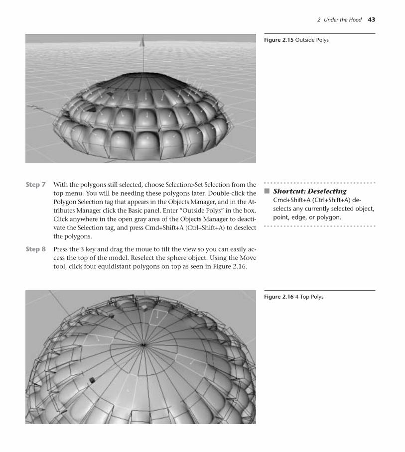
2 Under the Hood 43
Figure 2.15 Outside Polys
Step 7 With the polygons still selected, choose Selection>Set Selection from thetop menu. You will be needing these polygons later. Double-click thePolygon Selection tag that appears in the Objects Manager, and in the At-tributes Manager click the Basic panel. Enter “Outside Polys” in the box.Click anywhere in the open gray area of the Objects Manager to deacti-vate the Selection tag, and press Cmd+Shift+A (Ctrl+Shift+A) to deselectthe polygons.
Step 8 Press the 3 key and drag the moue to tilt the view so you can easily ac-cess the top of the model. Reselect the sphere object. Using the Movetool, click four equidistant polygons on top as seen in Figure 2.16.
Figure 2.16 4 Top Polys
■ Shortcut: DeselectingCmd+Shift+A (Ctrl+Shift+A) de-selects any currently selected object,point, edge, or polygon.

44 CINEMA 4D
Step 9 From the top menu, choose Structure>Edit Surface>Matrix Extrude. Inthe Matrix Extrude Box, enter 3 for Steps. Press Return (Enter).
Step 10 With the end polys still selected, choose Structure>Extrude Inner fromthe top menu.
In the Active Tool tab, enter –20 for the Offset value. (You could alsodrag the mouse to the right for interactive extrusion of the polygon.)
■ Shortcut: Extrude Inner Press the I key to access the Extrude Inner tool.Dragging the mouse to the right slides the new polygon away from the centerof the original polygon but keeps it moving along the same plane. Dragging tothe left slides the new polygon toward the center of the original polygon.
Step 11 Press the D key and drag the mouse from left to right in the editor win-dow to make the slightly elongated form in Figure 2.19. Press the I keyagain, but this time drag the mouse right to left to slide the new polytoward the center of the original one.
Figure 2.17 Matrix Extrude
Figure 2.18 Extrude Inner/Outward

2 Under the Hood 45
Figure 2.19 Extrude Again
Figure 2.20 Extrude Inner/Inward
Step 12 Press the D key one more time, and barely drag the mouse from rightto left in the window to make a slight depression in the form. SelectCenter and press Cmd+C (Ctrl+C) to copy it. Save the file (File>Save orCmd+S/Ctrl+S).
Step 13 Open the Petunia.c4d file in your Models folder (or choose it from theWindow menu if you didn’t close it) and use Cmd+V (Ctrl+V) to pastethe flower center into it. Choose the Model tool. Scale and move thecenter to fit inside the flower.
Using Set Selection
Step 1 Choose Unfold All from the Objects Manager menu, and drop the Pinkmaterial on the object Sphere inside the Center.
Step 2 In the Materials Manager, select File>New Material. Double-click theNew Material icon, and in the color property of the Material Editor,choose a medium green. Drop the green Material icon onto the nameSphere inside the Center.
Step 3 In the Attributes Manager, click the Tag panel and type the name ofthe Selection, Outside Polys, in the box next to Selection. Press Return
Figure 2.21 Center Close-Up
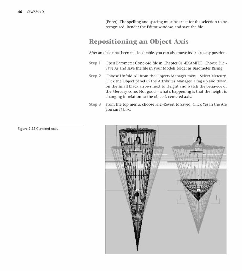
(Enter). The spelling and spacing must be exact for the selection to berecognized. Render the Editor window, and save the file.
Repositioning an Object Axis
After an object has been made editable, you can also move its axis to any position.
Step 1 Open Barometer Cone.c4d file in Chapter 01>EXAMPLE. Choose File>Save As and save the file in your Models folder as Barometer Rising.
Step 2 Choose Unfold All from the Objects Manager menu. Select Mercury.Click the Object panel in the Attributes Manager. Drag up and downon the small black arrows next to Height and watch the behavior ofthe Mercury cone. Not good—what’s happening is that the height ischanging in relation to the object’s centered axis.
Step 3 From the top menu, choose File>Revert to Saved. Click Yes in the Areyou sure? box.
46 CINEMA 4D
Figure 2.22 Centered Axes

Step 4 Working in the Front view, select the Mercury object again. Using the1 and 2 keys while dragging the mouse in the editor window, negoti-ate the view so you have a close-up look at the cone.
Step 5 Press the C key to make the Mercury object editable.
Step 6 From the left toolbar, choose the Object Axis tool.
Step 7 Use the green Move handle to move the object’s axis to the very bot-tom tip of the Mercury cone.
Step 8 From the left toolbar, choosethe Object tool.
Step 9 With the current time sliderat 0 frames, click the icon toenable animation of Scale.Choose the Scale tool, mak-ing sure all the X,Y, and Zlocks are free. Drag the mousein the editor window fromright to left until the Mercuryis barely visible. Press the F9key or click the Record button to set a keyframe.
Step 10 Go to the end of the animation. Drag the mouse from left to right, un-til the mercury level rises. See Figure 2.28. Set a keyframe. Press F8 orclick Play to preview the animation.
2 Under the Hood 47
Figure 2.23 Object Axis Tool
Figure 2.24 Axis Moved
Figure 2.25 Object Tool
Figure 2.26 0 Frames
Figure 2.27 Scale Animation Enabled
Figure 2.28 Low Level Close-up/High Level
◆ Tip: Use this same process to make the Line holding one of your modelsswing correctly from the top of the Pole. Just move the Line’s axis up to theSphere at the top of the Pole and animate the Line in a gentle rotation.
On the DVD: For more practice with adjusting Object Axes, see Chapter 02>EX-TRA!EXTRA!>InDepth>ROBOT Extra Project.

Creating and Repairing Polygonal Surfaces
You can make a single polygon by choosing Primitive>Polygon. In this section,you’ll learn how to “stitch” two separate surfaces together, how to use the bridgetool to connect meshes in useful ways and how to make a continuous polygo-nal surface. Note that these constructions are exercises designed to point outtechniques, and they are not how you would actually build these objects.
Stitching Meshes Together
Step 1 Choose File>Open and navigate to Chapter 02>C4D Files>Plastic Cur-tain.c4d. Choose Save As and save the file to your Models Folder.
Step 2 From the top toolbar, choose Primitive>Plane. Give the Plane 20 Widthsegments, 4 Height segments, and an Orientation of +Z. Press Return(Enter).
Step 3 Working in the Front view, Control-drag a copy of the Plane in the Ob-jects Manager. In the Editor window, use the red handle of the Movetool (be sure you are in the Model tool) to move the copy to the im-mediate right of the original. Shift-click both Planes to select them andpress the C key to make them editable.
48 CINEMA 4D
Figure 2.29 Plane
Figure 2.30 Side by Side Copies
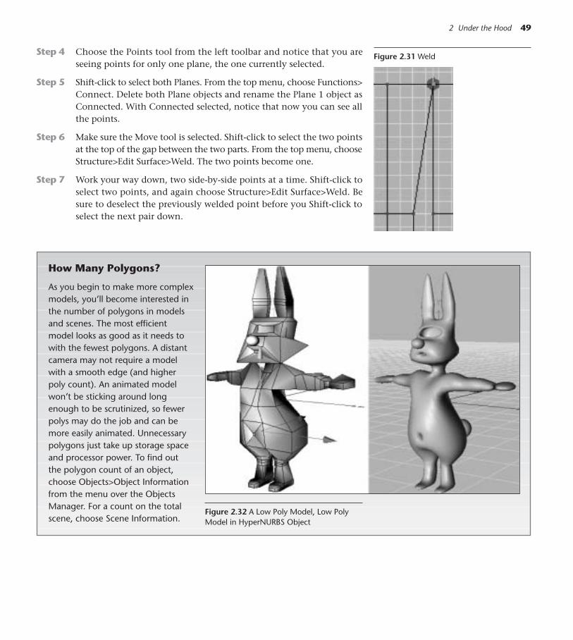
Step 4 Choose the Points tool from the left toolbar and notice that you areseeing points for only one plane, the one currently selected.
Step 5 Shift-click to select both Planes. From the top menu, choose Functions>Connect. Delete both Plane objects and rename the Plane 1 object asConnected. With Connected selected, notice that now you can see allthe points.
Step 6 Make sure the Move tool is selected. Shift-click to select the two pointsat the top of the gap between the two parts. From the top menu, chooseStructure>Edit Surface>Weld. The two points become one.
Step 7 Work your way down, two side-by-side points at a time. Shift-click toselect two points, and again choose Structure>Edit Surface>Weld. Besure to deselect the previously welded point before you Shift-click toselect the next pair down.
2 Under the Hood 49
Figure 2.31 Weld
How Many Polygons?
As you begin to make more complexmodels, you’ll become interested inthe number of polygons in modelsand scenes. The most efficientmodel looks as good as it needs towith the fewest polygons. A distantcamera may not require a modelwith a smooth edge (and higherpoly count). An animated modelwon’t be sticking around longenough to be scrutinized, so fewerpolys may do the job and can bemore easily animated. Unnecessarypolygons just take up storage spaceand processor power. To find outthe polygon count of an object,choose Objects>Object Informationfrom the menu over the ObjectsManager. For a count on the totalscene, choose Scene Information.
Figure 2.32 A Low Poly Model, Low PolyModel in HyperNURBS Object

50 CINEMA 4D
Making Models That Can Move
There are many ways of going aboutmaking any one model, and thereis usually a best way. In addition tothinking out a construction methodthat will be most efficient in polys,it’s important to think ahead on howyou want the model to be able tomove.
The number and orientation ofpolygons directly affect how wella model can be deformed and ani-mated later. Some old-fashionedsketching with pencil and paper canhelp you visualize how you want themodel to move and the best ap-proach for building it.
Figure 2.33 Nonmov-able and Movablemodel
Using the Knife Tool
Step 1 With the Points tool still selected, choose Structure>Knife from the topmenu.
Step 2 Hold down the Shift key. Click the mouse outside the top left of the plane(just under the top edge) and drag all the way across to the outside right.Make one more horizontal “cut” under the first one. Now knife verticallydown through the gap left from where you welded points. See Figure 2.34
■ Shortcut: Knifing Press the Kkey to access the Knife tool.
Figure 2.34 Subdivisions Made with theKnife Tool
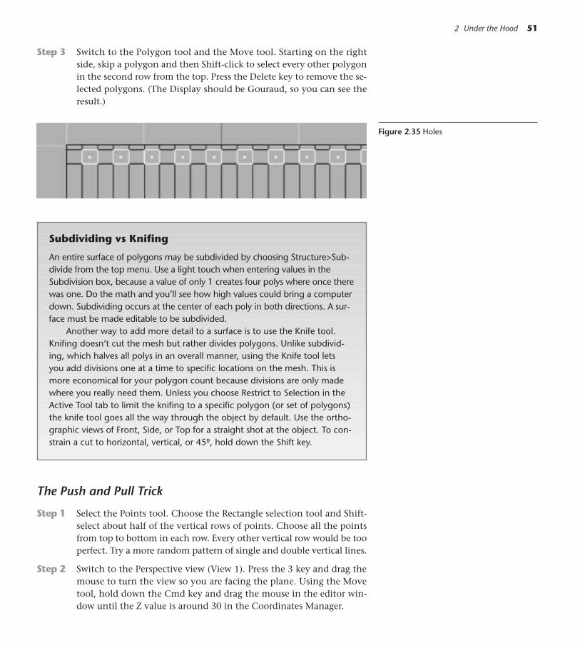
2 Under the Hood 51
Step 3 Switch to the Polygon tool and the Move tool. Starting on the rightside, skip a polygon and then Shift-click to select every other polygonin the second row from the top. Press the Delete key to remove the se-lected polygons. (The Display should be Gouraud, so you can see theresult.)
Figure 2.35 Holes
Subdividing vs Knifing
An entire surface of polygons may be subdivided by choosing Structure>Sub-divide from the top menu. Use a light touch when entering values in theSubdivision box, because a value of only 1 creates four polys where once therewas one. Do the math and you’ll see how high values could bring a computerdown. Subdividing occurs at the center of each poly in both directions. A sur-face must be made editable to be subdivided.
Another way to add more detail to a surface is to use the Knife tool.Knifing doesn’t cut the mesh but rather divides polygons. Unlike subdivid-ing, which halves all polys in an overall manner, using the Knife tool lets you add divisions one at a time to specific locations on the mesh. This ismore economical for your polygon count because divisions are only madewhere you really need them. Unless you choose Restrict to Selection in theActive Tool tab to limit the knifing to a specific polygon (or set of polygons)the knife tool goes all the way through the object by default. Use the ortho-graphic views of Front, Side, or Top for a straight shot at the object. To con-strain a cut to horizontal, vertical, or 45º, hold down the Shift key.
The Push and Pull Trick
Step 1 Select the Points tool. Choose the Rectangle selection tool and Shift-select about half of the vertical rows of points. Choose all the pointsfrom top to bottom in each row. Every other vertical row would be tooperfect. Try a more random pattern of single and double vertical lines.
Step 2 Switch to the Perspective view (View 1). Press the 3 key and drag themouse to turn the view so you are facing the plane. Using the Movetool, hold down the Cmd key and drag the mouse in the editor win-dow until the Z value is around 30 in the Coordinates Manager.
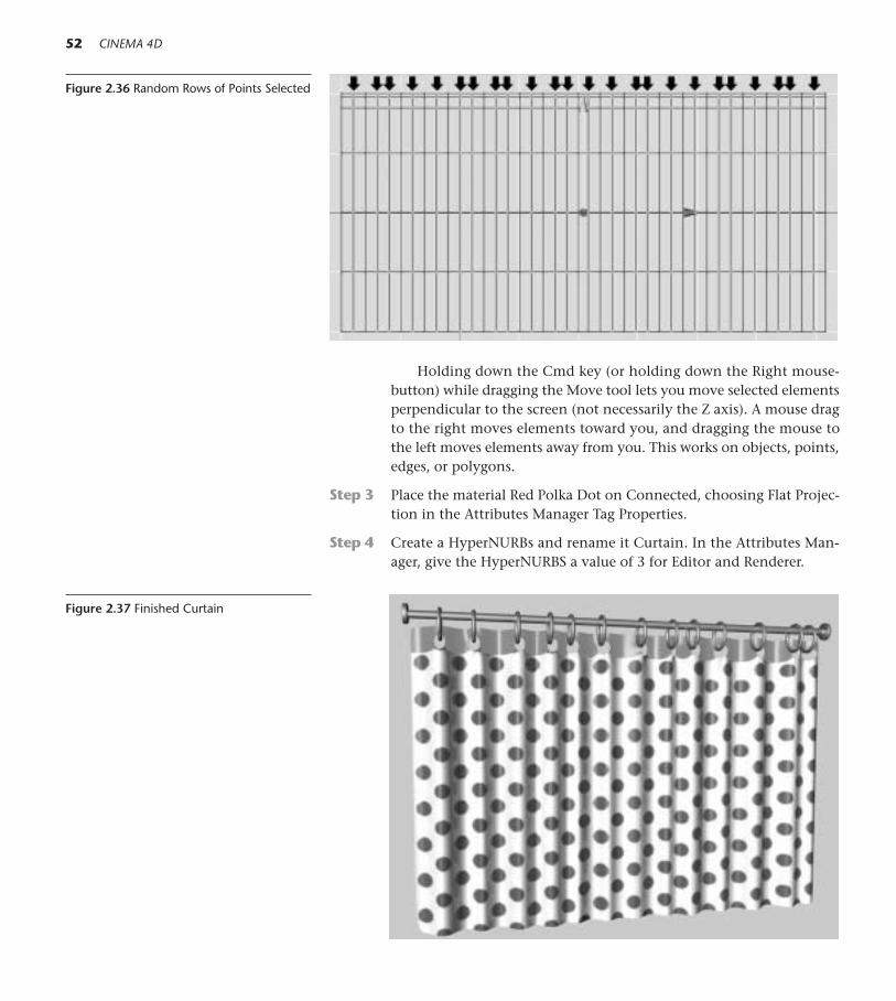
Holding down the Cmd key (or holding down the Right mouse-button) while dragging the Move tool lets you move selected elementsperpendicular to the screen (not necessarily the Z axis). A mouse dragto the right moves elements toward you, and dragging the mouse tothe left moves elements away from you. This works on objects, points,edges, or polygons.
Step 3 Place the material Red Polka Dot on Connected, choosing Flat Projec-tion in the Attributes Manager Tag Properties.
Step 4 Create a HyperNURBs and rename it Curtain. In the Attributes Man-ager, give the HyperNURBS a value of 3 for Editor and Renderer.
52 CINEMA 4D
Figure 2.36 Random Rows of Points Selected
Figure 2.37 Finished Curtain

2 Under the Hood 53
Step 5 Drop the Connected object into the HyperNURBS object and type Ctrl+Rto admire your curtain.
The Magnet Tool and Point Level Animation
Step 1 Chose File>Open and navigate to Chapter 02>C4D Files>Moving Cur-tain.c4d. Save a copy of the file into your Models folder (File>Save As).Use the Perspective view.
Step 2 Choose Selection>Deselect All to assure there are no selected points.
Step 3 Choose Structure>Magnet tool. Make sure all X,Y, and Z locks are free.
Step 4 In the Active Tool Manager, enter a Radius of 300m.
Step 5 In the Animation toolbar, make sure only the PLA icon is enabled foranimation.
Step 6 At frames 0 and 90, click the Record button to record keyframes for “neu-tral” positions of the curtain before any Magnet tool is applied.
Step 7 At frame 45, mouse with the Magnet tool to billow the bottom edge ofthe curtain out slightly. Set a keyframe.
Step 9 Press F8 or click Play to preview the animation.
Figure 2.38 X,Y and Z Locks in UnlockedState
Figure 2.39 PLA Enabled
Figure 2.40 Moving Curtain

P Is for Pipe
For more practice with mesh construction, let’s make the letter P in an unortho-dox way.
Step 1 Chose File>Open and navigate to Chapter 02>C4D Files>P for PIPE.c4d.Choose File>Save As and save the file to your Models Folder. Render theexisting model to see what you will be making, then select the Pipe anddelete it.
Step 2 Working in the Front view, choose the Points tool. From the top menu,choose Objects>Polygon Object. Using the Move tool, hold down theCtrl key and click points in the configuration shown in Figure 2.41.
Step 3 From the top menu, choose Structure>Bridge. Click on the upper leftpoint and drag across to the upper right point. Both points will turnred. Now drop down to the next row. Click the left point and drag tothe one to its right. Continue this maneuver, moving downward, untilyou reach the bottom.
54 CINEMA 4D
Step 4 Press Cmd+Shift+A (Ctrl-Shift-A) to deselect.
Step 5 Start again at the top of thepoint structure and repeatthe left-to-right drags in an-other vertical row. Deselect
Figure 2.41 Points for P Figure 2.42 First Row Figure 2.43 Second RowFigure 2.44 A Copy of the Polygon MovedBehind
■ Shortcut: The Bridge ToolPress the B key to access the Bridgetool, which lets you quickly build acontinuous mesh on points you havedrawn. When you reach the end ofany section you are bridging, youmust deselect the points beforemoving to another section.
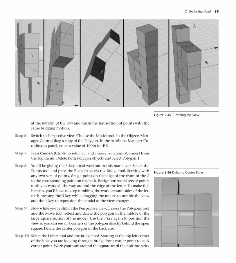
at the bottom of the row and finish the last section of points with thesame bridging motion.
Step 6 Switch to Perspective view. Choose the Model tool. In the Objects Man-ager, Control-drag a copy of the Polygon. In the Attributes Manager Co-ordinates panel, enter a value of 100m for P.Z.
Step 7 Press Cmd+A (Ctrl-A) to select all, and choose Functions>Connect fromthe top menu. Delete both Polygon objects and select Polygon 1.
Step 8 You’ll be giving the 3 key a real workout in this maneuver. Select thePoints tool and press the B key to access the Bridge tool. Starting withany two sets of points, drag a point on the edge of the front of the Pto the corresponding point on the back. Bridge horizontal sets of pointsuntil you work all the way around the edge of the letter. To make thishappen, you’ll have to keep tumbling the world around sides of the let-ter P, pressing the 3 key while dragging the mouse to tumble the viewand the 1 key to reposition the model as the view changes.
Step 9 Now while you’re still in the Perspective view, choose the Polygons tooland the Move tool. Select and delete the polygon in the middle of thelarge square section of the model. Use the 3 key again to position theview so you can see all 4 corners of the polygon directly behind the opensquare. Delete the center polygon in the back also.
Step 10 Select the Points tool and the Bridge tool. Starting at the top left cornerof the hole you are looking through, bridge front corner point to backcorner point. Work your way around the square until the hole has sides
2 Under the Hood 55
Figure 2.45 Tumbling the View
Figure 2.46 Deleting Center Polys

56 CINEMA 4D
all around. At times, you may have to use the 3 key to tilt the viewslightly so you can see both target points.
Step 11 Create a HyperNURBS, and drop the Polygon.1 object into it. Assigna Phong tag to Polygon.1 and check the Angle Limit box. Set a valueof 3 for HyperNURBS Editor and Renderer. Rename the HyperNURBSas Pipe.
Finishing Touches for the Pipe
Step 1 Choose the Polygons tool. Working on the Polygon.1 object inside theHyperNURBS, Shift-click to select the top and bottom polys on the long,vertical part of the letter P. Press the I key and in the Active Tool Man-ager, enter an offset value of –50m. Remember to click Apply or press Re-turn (Enter) after entering values in the Active Tool Manager.
Step 2 Press the D key. Enter a value of 50 for Offset in the Active Tool Manager.
Step 3 Press the I key again, and set the Offset value to 60.
Step 4 Press the D key one last time,and enter –300 for Offset.
Figure 2.47 Bridging Though
Figure 2.48 Top and Bottom Polys
Figure 2.49 Polys Extrude Inner
Figure 2.50 Extrude Pipe
Figure 2.51 Top Extrude Inner
Figure 2.52 Extrude Down Into
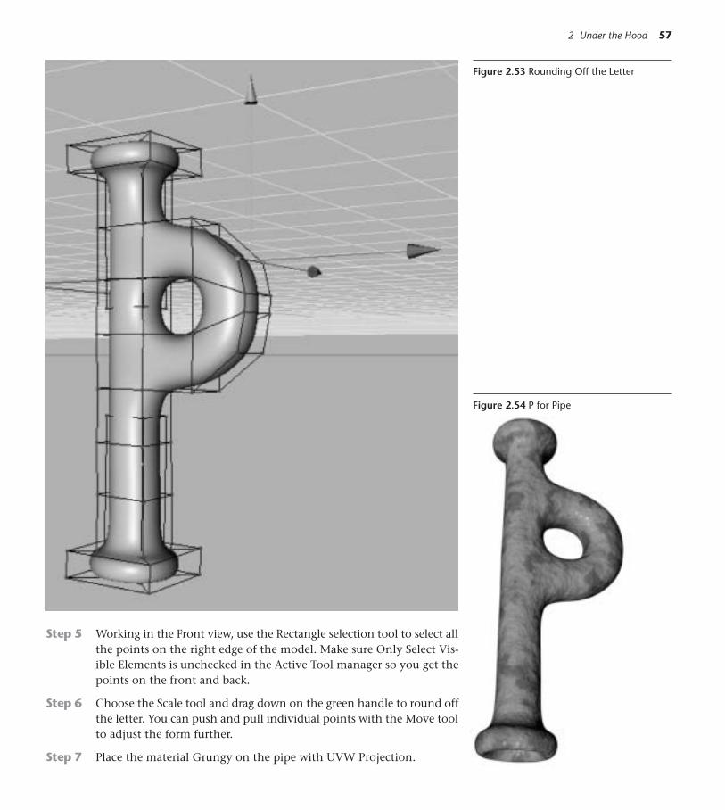
2 Under the Hood 57
Step 5 Working in the Front view, use the Rectangle selection tool to select allthe points on the right edge of the model. Make sure Only Select Vis-ible Elements is unchecked in the Active Tool manager so you get thepoints on the front and back.
Step 6 Choose the Scale tool and drag down on the green handle to round offthe letter. You can push and pull individual points with the Move toolto adjust the form further.
Step 7 Place the material Grungy on the pipe with UVW Projection.
Figure 2.53 Rounding Off the Letter
Figure 2.54 P for Pipe
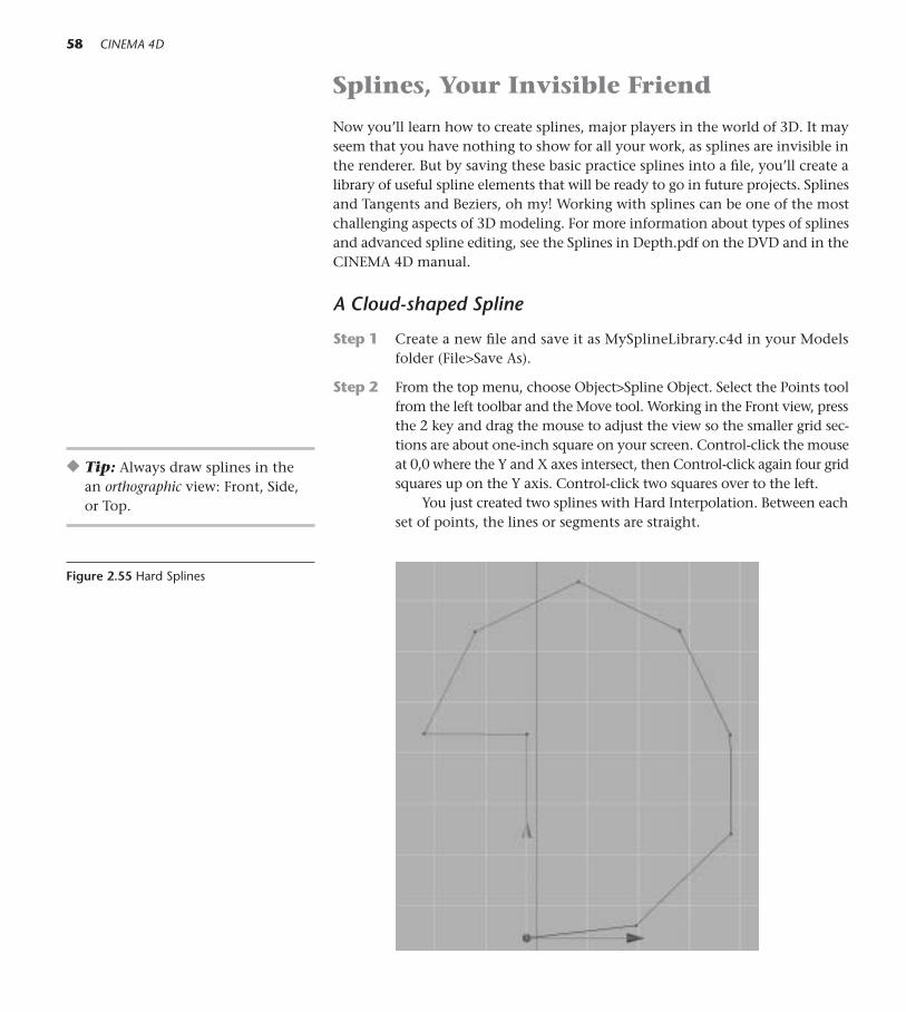
Splines, Your Invisible Friend
Now you’ll learn how to create splines, major players in the world of 3D. It mayseem that you have nothing to show for all your work, as splines are invisible inthe renderer. But by saving these basic practice splines into a file, you’ll create alibrary of useful spline elements that will be ready to go in future projects. Splinesand Tangents and Beziers, oh my! Working with splines can be one of the mostchallenging aspects of 3D modeling. For more information about types of splinesand advanced spline editing, see the Splines in Depth.pdf on the DVD and in theCINEMA 4D manual.
A Cloud-shaped Spline
Step 1 Create a new file and save it as MySplineLibrary.c4d in your Modelsfolder (File>Save As).
Step 2 From the top menu, choose Object>Spline Object. Select the Points toolfrom the left toolbar and the Move tool. Working in the Front view, pressthe 2 key and drag the mouse to adjust the view so the smaller grid sec-tions are about one-inch square on your screen. Control-click the mouseat 0,0 where the Y and X axes intersect, then Control-click again four gridsquares up on the Y axis. Control-click two squares over to the left.
You just created two splines with Hard Interpolation. Between eachset of points, the lines or segments are straight.
58 CINEMA 4D
◆ Tip: Always draw splines in the an orthographic view: Front, Side,or Top.
Figure 2.55 Hard Splines

Step 3 Use the 1 and 2 keys with the mouse to adjust the view so you can con-tinue to Control-click points in the configuration seen in Figure 2.55.Make the last click on the point you started on. This creates a closedspline.
Step 4 Skipping over the first three points you drew, shift-click to select all theother points on the spline. From the top menu, choose Structure>EditSpline>Soft Interpolation. Deselect the points by typing Cmd+Shift+A(Ctrl+Shift+A), then click on just one of them.
Converting these points to Soft Interpolation causes the splines tocurve out of the points. The magenta tangent handles control the di-rection and expansion of the curve. Drag a tangent handle out from itspoint to see how it flattens the curve. Then, move the handle up anddown in a seesaw motion. Notice how the opposite ends of the curvemove in a connected way. Click the Move tool on a point, and then dragthe Move handles to change the location slightly. Double-click on apoint. A box appears with numerical values for the point and its tan-gents. Holding down the Shift key and independently dragging a han-dle allows you to break the rigid tangent and send the opposite ends ofthe tangent in different directions. Use Cmd+Z (Ctrl+Z) to undo theseexperiments!
Step 5 Shift-click to select the fourth point you made. Continue to hold theShift key and drag the tangent handles independently. To make a cloud
2 Under the Hood 59
Figure 2.56 Tangent Handles
Figure 2.57 Cloud Spline

outline, move the tangent handles closer together so they dip inward.Leave the first three points you drew as they are, but edit all the oth-ers to create the outline of a puffy cloud. Use the Move tool to movepoints if necessary.
Step 6 When you are satisfied with your cloud shape, rename the spline asCloud and click the top gray button in the second column of the Ob-jects Manager to turn off its visibility.
A Lightbulb Spline
You made the cloud spline by creating an empty spline object and Control-click-ing points to go inside it. This time, you’ll use an interactive spline tool to createa Bezier Spline on the fly. The cool thing about splines is that they can always beedited later, even when they are a working component of a finished model.
Step 1 Work in the Front view. From the top toolbar, choose Spline>BezierSpline Tool.
60 CINEMA 4D
Figure 2.58 Bezier Spline Tool
Beginning on the Y axis, click a point. Release the mouse. Then,drop slightly down and to the right, but this time click and drag overslightly to the right as you click to create tangent handles for thepoint.
Any time you click and drag a point, it is “born” with Soft Inter-polation and has tangent handles.
Step 2 Position the next point as shown in Figure 2.60 and drag the tangenthandle down and to the left, stretching it out to round out the curve.Click (but don’t drag) the next point one grid unit directly below thelast. Click (but don’t drag) a last point horizontally to the left and backon the Y axis.
Step 3 Rename the Spline as Bulb 1. Control-drag a copy of it. Turn off editorvisibility for the original, and name the copy Bulb 2.
Figure 2.59 Light-bulb Start
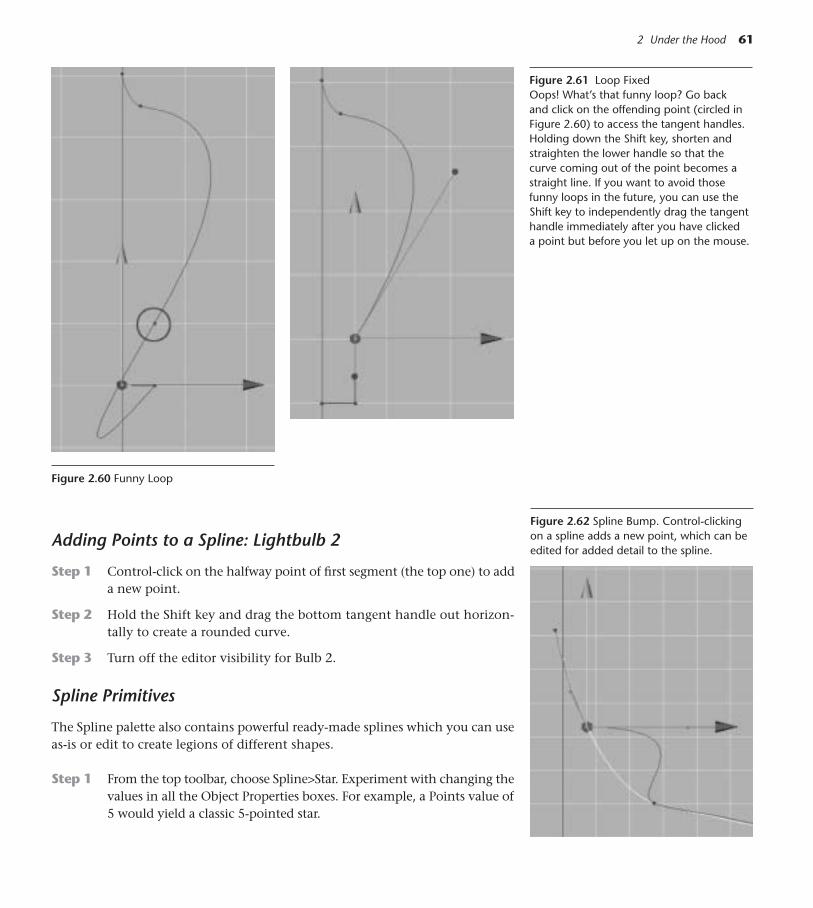
2 Under the Hood 61
Adding Points to a Spline: Lightbulb 2
Step 1 Control-click on the halfway point of first segment (the top one) to adda new point.
Step 2 Hold the Shift key and drag the bottom tangent handle out horizon-tally to create a rounded curve.
Step 3 Turn off the editor visibility for Bulb 2.
Spline Primitives
The Spline palette also contains powerful ready-made splines which you can useas-is or edit to create legions of different shapes.
Step 1 From the top toolbar, choose Spline>Star. Experiment with changing thevalues in all the Object Properties boxes. For example, a Points value of5 would yield a classic 5-pointed star.
Figure 2.60 Funny Loop
Figure 2.61 Loop FixedOops! What’s that funny loop? Go back and click on the offending point (circled inFigure 2.60) to access the tangent handles.Holding down the Shift key, shorten andstraighten the lower handle so that thecurve coming out of the point becomes astraight line. If you want to avoid thosefunny loops in the future, you can use theShift key to independently drag the tangenthandle immediately after you have clickeda point but before you let up on the mouse.
Figure 2.62 Spline Bump. Control-clickingon a spline adds a new point, which can beedited for added detail to the spline.

Now enter 100 for Points, 185 for Inner Radius, and 85 percent forTwist. Whoa! A saw blade.
Step 2 Press the C key to make the Star Spline editable. Switch to the Perspec-tive view. Use the Move tool to select points on the primitive and movethem anywhere in the 3D space. Remember, you can also Control-clickon these splines to add points and detail. If you want to delete an ex-isting point, just select the point and press the Delete (Backspace) key.
Creating Complex Splines with Create Outline
Step 1 In the Front View, choose Spline>Flower Spline.
62 CINEMA 4D
Step 2 Press the C key to make the spline editable.
Step 3 From the top menu, choose Structure>Edit Spline>Create Outline.
Step 4 Drag on the flower spline with the tool. After dragging one outline, goback and drag on one or two others. (The separate outlines will remainas one spline object.)
Step 5 Rename Flower as Complex Spline and turn off its visibility for now.
Figure 2.63 Star Possibilities
Figure 2.64 Flower Spline

2 Under the Hood 63
On the DVD: All the splines in Chapter 02>C4D Files>Spline Library.c4d on theDVD may be made with the skills you just learned. Turn on their visibility oneat a time and practice making them. Save this Library and add your own splinesto it for future use.
Importing Splines
CINEMA 4D can import splines from any vector program or custom shapes fromAdobe Photoshop. In Chapter 17, you’ll learn how. Also, the Internet has a wealthof custom shape libraries and type outlines that slide right into CINEMA 4D andmake themselves at home!
On the DVD: For more “Under the Hood” skills, see Chapter 02>EXTRA!EX-TRA!>InDepth>More About Splines.
Figure 2.66 A Spline LibraryFigure 2.65 A More Complex Spline

This Page Intentionally Left Blank
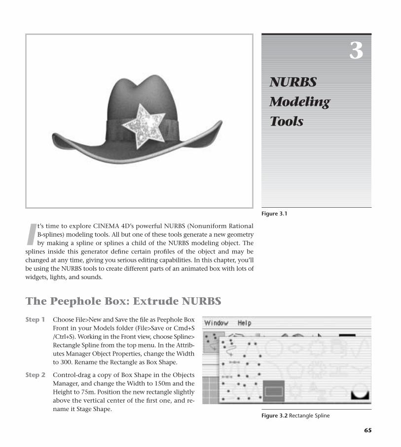
I t’s time to explore CINEMA 4D’s powerful NURBS (Nonuniform RationalB-splines) modeling tools. All but one of these tools generate a new geometryby making a spline or splines a child of the NURBS modeling object. The
splines inside this generator define certain profiles of the object and may bechanged at any time, giving you serious editing capabilities. In this chapter, you’llbe using the NURBS tools to create different parts of an animated box with lots ofwidgets, lights, and sounds.
The Peephole Box: Extrude NURBS
Step 1 Choose File>New and Save the file as Peephole BoxFront in your Models folder (File>Save or Cmd+S/Ctrl+S). Working in the Front view, choose Spline>Rectangle Spline from the top menu. In the Attrib-utes Manager Object Properties, change the Widthto 300. Rename the Rectangle as Box Shape.
Step 2 Control-drag a copy of Box Shape in the ObjectsManager, and change the Width to 150m and theHeight to 75m. Position the new rectangle slightlyabove the vertical center of the first one, and re-name it Stage Shape.
3NURBSModeling Tools
65
Figure 3.1
Figure 3.2 Rectangle Spline

Step 3 Now choose Spline>Circle. Give the Circle a Radius of 40 and center itbelow the small rectangle. Control-drag two copies of the Circle. Shift-click to select them and enter a Radius of 30m. Position them slightlyabove and to each side of the first Circle. Use Figure 3.3 and the editorgrid lines as a guide for positioning. Name the circles Circle 1, Circle2, and Circle 3.
Step 4 Shift-click to select all three circles, and press G to Group them. Renamethe Group as Bottom Circles. Control-drag a copy of Bottom Circles, andrename the copy as Top Circles. Click the (+) next to Top Circles, and re-name the circles inside Circle 4, Circle 5, and Circle 6. Select Top Circles,and use the green handle of the Move tool to position that group of cir-cles above the Stage Shape in the Editor window.
Step 5 With Top Circles still selected, click the Coordinates panel in the Attrib-utes Manager and enter a value of 180º for R.B (Bank) to flip the circles.
Step 6 From the menu above the Objects Manager, choose Objects>Unfold All.Shift-click to select Circles 1 though 6, Stage Shape, and Box Shape. Pressthe C key to make all objects in the multiple selection editable. Select BoxShape and choose the Points tool. Using the Scale tool, Shift-click to se-lect the bottom two points on the Box Shape spline. Drag the mouseright to left until the bottom of the shape is slightly tapered. Refer to Fig-ure 3.4.
Step 7 Shift-click to select Circles 1 though 6, Stage Shape, and Box Shape again.Choose Functions>Connect. Rename the new spline object Circle as BoxFace Template.
66 CINEMA 4D
Figure 3.3 Stage and Bottom Circle Outlines

Step 8 Move the mouse to the NURBS toolicon in the top palette, and drag tochoose an Extrude NURBS object.Drop the Box Face Template onto theobject Extrude NURBS. Rename Ex-trude NURBS as Box Front.
Step 9 With Box Front selected, click the Ob-ject panel in the Attributes Manager.Enter 3m in the Movement box on the far right side (the Z value).
Step 10 Click the panel for Caps. In the Start pulldown menu, choose Fillet Cap.Enter 3 for Steps and 5m for Radius. In the Fillet Type pulldown menu,choose Half Circle. Save the File (File>Save or Cmd+S/Ctrl+S).
3 NURBS Modeling Tools 67
Figure 3.4 Box Face Template
Figure 3.5 Extrude NURBS
Figure 3.6 Peephole Box Front

Box Top Decoration: Loft Nurbs
Step 1 Choose File>Open and navigate to Chapter 02>C4D Files>Spline Libraryon the DVD. Copy the Profile for Loft spline using Cmd+C (Ctrl+C).Close the file (File>Close).
Step 2 Choose File>New and working in the Front view, paste the spline withCmd+V (Ctrl+V). Choose Edit>Frame Scene. Use the green handle ofthe Move tool to raise the spline so it sits on the X axis, and rotate thespline 90º H (Heading). Choose File>Save or Cmd+S (Ctrl+S) and savethe file as Box Top Detail to your Models folder.
Step 3 Control-drag nine copies of the spline. Rename the Splines Profile 1,Profile 2 through Profile 10.
Step 4 Make sure you are in the Model tool. Using the blue Move handle, dragProfile 1 four grid large units to the left. In the Coordinates panel, entera Rotation P value of –90. Refer to the lefthand spline in Figure 3.8.
Step 5 Select the Profile 2 and drag it to the right side of the first profile. Con-tinue dragging the remaining splines, in numerical order, until theyare lined up 1/2 large grid units apart.
Step 6 Select Profile 2 and use the Rotate tool to lean it toward the left side–45º. Shift-click to select Profiles 3, 5, 7, and 9. Select the Scale tool anddrag the green Scale handle down until the splines are about half theheight of Profile 2.
68 CINEMA 4D
NURBS Tools at a Glance
NURBS (Nonuniform RationalB-splines) have no polygonsof their own but are algorith-mically calculated surfaces.Most NURBS generate objectsfrom elements or objectsplaced inside them.
• The HyperNURBS rounds off an object placed inside it into a more curvilinear, organic version of the moregeometric original.
• The Extrude NURBS extends a shape as an extrusion,using a 2D object to create a 3D object.
• The Lathe NURBS revolves a profile spline in a rotationaround the Y axis to create surfaces. Think thrownpottery or wood turning.
• The Loft NURBS stretches a surface over profilesplines or ribs. A single spline will create a flat object,while any number of multiple ribs will create 3D sur-faces that change according to their profiles. LoftNURBS may be created from open or closed splines.
• The Sweep NURBS moves a profile spline along thepath of another spline. The profile may be scaled as itmoves along the path, and the path may be ani-mated to grow.
• The Bezier NURBS is simply a surface defined by Xand Y Bezier curves with control points. This is theonly NURBS tool that requires no child objects.
Figure 3.7 The NURBS Tools
Peepholes: Splines inside Splines
CINEMA 4D interprets a spline ormultiple splines inside a spline asa hole in the shape. All thesplines must first be made ed-itable. Selecting all the splinesand choosing Functions>Connectwill combine all the splines into asingle spline object.
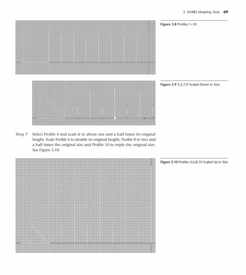
3 NURBS Modeling Tools 69
Figure 3.8 Profiles 1–10
Figure 3.9 3,5,7,9 Scaled Down in Size
Figure 3.10 Profiles 4,6,8,10 Scaled Up in Size
Step 7 Select Profile 4 and scale it to about one and a half times its originalheight. Scale Profile 6 to double its original height, Profile 8 to two anda half times the original size and Profile 10 to triple the original size.See Figure 3.10.

Step 8 From the NURBS tool palette, choose a Loft NURBS object. Rename itas Box Top Detail.
Step 9 Starting with Profile 1 and continuing in order, drop the objects Pro-files 1 though 10 onto the Loft NURBS. Choose Display>Wireframe.
Step 10 From the Window menu, choose New View Panel. Enlarge the window,choose Gouraud shading and navigate so you have a good view of themodel surface. While looking at the model in the new view, work in thewireframe view. Use the blue handle of the Move tool and the Rotate toolto move and rotate the splines so you design the decoration to your lik-ing. This Loft object will be half of the finished decoration, so you maywant to rotate the splines all to the left. See Figure 3.12. Save using File>Save or Cmd+S (Ctrl+S).
70 CINEMA 4D
Figure 3.11 Loft NURBS
Figure 3.12 The Loft Object inTwo Windows.Once a spline has been rotated, its axes aretilted. To move the spline only along the Xaxis, choose the World Coordinate Systemicon from the top toolbar. Then choose theMove tool and make sure the X lock on thetop toolbar is the only one unlocked.
Figure 3.13 World Coordinates
Figure 3.14 Loft Decoration

Curly Glass Tubes: The Sweep NURBS
Step 1 Choose File>New and Save the file as Curly Glass Tube in your Modelsfolder (File>Save or Cmd+S/Ctrl+S).
Step 2 In the Front view, choose Spline>Helix from the top toolbar. In the At-tributes Manager Coordinates panel, enter–90º in the R.H box and pressreturn to rotate the Helix on the Heading. In Object Properties, entera Start and End Radius of 100, an End Angle of 1450, a Height of 500m,a Height Bias of 25 percent and Subdivisions of 20.
◆ Tip: Want a quick way to figure out what all these Helix settings do? Make a helix, then drag the small black arrows next to each of the valueswhile watching the effects realtime in the Perspective view.
Step 3 With the Helix selected, press the C key to make it editable. Choosethe Points tool and the Move tool. Hold down the Ctrl key and click anew point on the left side of the Helix, three grid units down and threegrid units to the left. Move the second point more to the left and usethe tangent handles to round out the curve.
3 NURBS Modeling Tools 71
Figure 3.15 Helix Spline
Figure 3.16 Helix Settings
Step 4 Click the Editor window to make it active, and press Cmd+A(Ctrl+A) to select all the points on the Helix. Choose Struc-ture>Mirror. Click the point on the far right end of the Helix.(If your mirroring flips on a different axis and does not end
Figure 3.17 Smoothing Curve

up looking like Figure 3.18, use the Undo command and try again untilyou click on just the right spot. For future reference, notice that in theActive Tool tab you can set the mirroring to occur on any axis or coor-dinate system.)
72 CINEMA 4D
Figure 3.18 Mirrored Points
Step 5 Choose Spline>Circle and give the Circle a Radius of 15. You can makethe tube any thickness you want at any time by scaling the circle.
Step 6 Choose NURBS>Sweep NURBS. Drop the path spline in first (the Helix)and then drop the cross section profile (the Circle).
Step 7 Rename the Sweep NURBS as Coil One. Control-drag a copy of it andname the copy Coil Two. Choose the Model tool and the Move tool.In the Top view, move Coil Two in front of Coil One.
Step 8 Choose Display>Isoparm. With the Points tool chosen, select the Helixinside each coil and use the Move tool to carefully edit the point po-sitions and tangents so that the coils look smooth in top view. Notethat deleting some points may help you structure a smoother coil.
Step 9 Still in Points, edit Coil Two to look slightly different from Coil One.Remove some points, move some others, and then switch to the Modeltool and scale the whole tube to be about 85 percent smaller than CoilOne. Save the file (File>Save or Cmd+S/Ctrl+S), then choose File>Save Asand save a copy as Animated Tube. Leave the animated Tube file openfor the next exercise.
Figure 3.19 Sweep NURBS
Figure 3.20 Coil Differences Front View

Time for a Sideshow: Animating Sweep NURBS
Step 1 Working in the file Animated Tube, delete the Coil Two object, and se-lect Coil One.
Step 2 Make sure the current time is at 0 frames.
Step 3 In the Attributes Manager Object Properties, enter 0 percent in the boxfor Growth. Command-click on the word Growth and slide to Anima-tion>Add Keyframe.
Step 4 Move the current time to the end of the animation.
Step 5 Enter 100 percent in the Growth box and set a keyframe. Play the An-imation.
Remember that this spline was originally mirrored, which accounts for theinteresting growth from one end and then the other. When the growth of a non-mirrored spline is animated, the Sweep NURBS simply grows from the beginningof the path spline to the end. If you want the spline to grow from the oppositeend, select the path spline and choose Structure>Edit Spline>Reverse Sequence.
Antique Lightbulbs: Lathe NURBS
Step 1 Choose File>Open and navigate to Chapter 02>C4D Files>Spline Libraryon the DVD. Click the (+) next to Lightbulbs and select Bulb 2. PressCmd+C (Ctrl+C) to copy the spline. Leave the file open.
Step 2 Choose File>New and working in the Front view, paste the spline withCmd+V (Ctrl+V). Save the new file as Antique Bulbs to your Modelsfolder (File>Save As). Choose Edit>Frame Scene.
Notice how the spline is positioned in relation to the Y Axis, andthat the Bulb’s object axis is on the Y axis. A Lathe NURBS will always
3 NURBS Modeling Tools 73
Figure 3.21 Coil Differences Top View
3D Famous Saying
“Ten percent of your time will bespent making something, and 90percent of your time will be spentmaking it look dirty, full of dinksand dents and otherwise like it’san inhabitant of real life.” Inother words, you have to workhard to keep 3D models fromlooking “too perfect.” Coil Two isa good example. It needs someaberrations and differences tokeep it from being just a stalecopy of Coil One. See what youcan do.
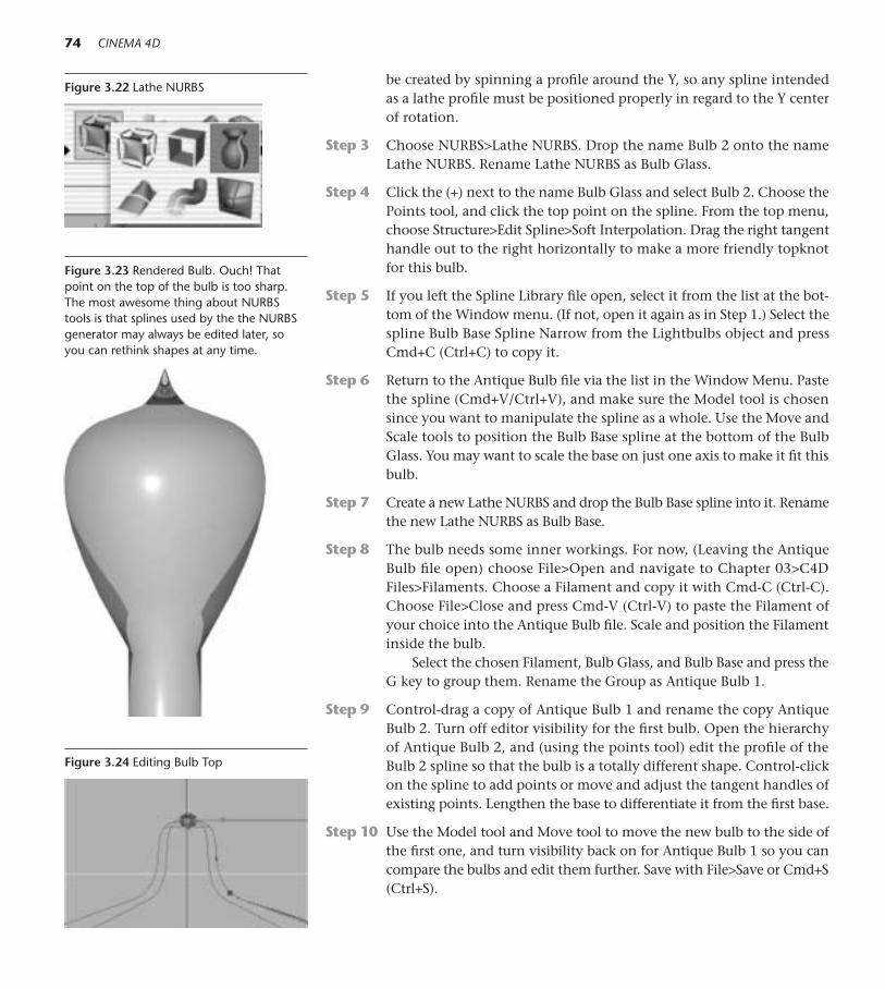
be created by spinning a profile around the Y, so any spline intendedas a lathe profile must be positioned properly in regard to the Y centerof rotation.
Step 3 Choose NURBS>Lathe NURBS. Drop the name Bulb 2 onto the nameLathe NURBS. Rename Lathe NURBS as Bulb Glass.
Step 4 Click the (+) next to the name Bulb Glass and select Bulb 2. Choose thePoints tool, and click the top point on the spline. From the top menu,choose Structure>Edit Spline>Soft Interpolation. Drag the right tangenthandle out to the right horizontally to make a more friendly topknotfor this bulb.
Step 5 If you left the Spline Library file open, select it from the list at the bot-tom of the Window menu. (If not, open it again as in Step 1.) Select thespline Bulb Base Spline Narrow from the Lightbulbs object and pressCmd+C (Ctrl+C) to copy it.
Step 6 Return to the Antique Bulb file via the list in the Window Menu. Pastethe spline (Cmd+V/Ctrl+V), and make sure the Model tool is chosensince you want to manipulate the spline as a whole. Use the Move andScale tools to position the Bulb Base spline at the bottom of the BulbGlass. You may want to scale the base on just one axis to make it fit thisbulb.
Step 7 Create a new Lathe NURBS and drop the Bulb Base spline into it. Renamethe new Lathe NURBS as Bulb Base.
Step 8 The bulb needs some inner workings. For now, (Leaving the AntiqueBulb file open) choose File>Open and navigate to Chapter 03>C4DFiles>Filaments. Choose a Filament and copy it with Cmd-C (Ctrl-C).Choose File>Close and press Cmd-V (Ctrl-V) to paste the Filament ofyour choice into the Antique Bulb file. Scale and position the Filamentinside the bulb.
Select the chosen Filament, Bulb Glass, and Bulb Base and press theG key to group them. Rename the Group as Antique Bulb 1.
Step 9 Control-drag a copy of Antique Bulb 1 and rename the copy AntiqueBulb 2. Turn off editor visibility for the first bulb. Open the hierarchyof Antique Bulb 2, and (using the points tool) edit the profile of theBulb 2 spline so that the bulb is a totally different shape. Control-clickon the spline to add points or move and adjust the tangent handles ofexisting points. Lengthen the base to differentiate it from the first base.
Step 10 Use the Model tool and Move tool to move the new bulb to the side ofthe first one, and turn visibility back on for Antique Bulb 1 so you cancompare the bulbs and edit them further. Save with File>Save or Cmd+S(Ctrl+S).
74 CINEMA 4D
Figure 3.22 Lathe NURBS
Figure 3.23 Rendered Bulb. Ouch! Thatpoint on the top of the bulb is too sharp.The most awesome thing about NURBStools is that splines used by the the NURBSgenerator may always be edited later, soyou can rethink shapes at any time.
Figure 3.24 Editing Bulb Top

3 NURBS Modeling Tools 75
● Springboard! You will need a variety of Antique bulbs for the Peephole Box.Make them all in the Antique Bulbs file, using visibility to isolate individual bulbs as you work on them. Make some of your own sets of Inner Parts using BezierSplines, Helix splines, and other basic modeling you have already mastered. Inventa bulb with spinning parts. (You could reuse the Galaxy Ball from Chapter 1.) Thereare some more bulb and base splines in the Spline Library for your use, and you can create more of your own. Research antique light bulbs on the web for ideas.
On the DVD: See the Library of finished bulbs in Chapter 03>EXAMPLE>AntiqueBulbs.
Figure 3.27 Antique Bulbs
Figure 3.25 New Bulb Top Figure 3.26 Bulb Base

The Stage Curtain: The Bezier NURBS
Step 1 Choose File>New and save the file as Stage Curtains into your Mod-els folder (File>Save or Cmd+S/Ctrl+S). Work in the Front view.
Step 2 From the top toolbar, choose NURBS>Bezier NURBS.
Step 3 In the Attributes Manager Object Properties, enter 15 for Subdivision X.
Step 4 Click the Coordinates panel. With the current time at 0 frames, entera value of 1.25 for S.X and Command-drag (or right-click) to Anima-tion>Add Keyframe. Go to the end of the animation, change the S.Xvalue to 0.25 and set a keyframe.
Play the animation. By animating the scale of the Bezier NURBSon the X axis, you created the basic motion for opening the curtains.
Step 5 Press the C key. Select the Object Axis tool and the Move tool. Movethe axis for the Bezier NURBS to the far left side of the object.
Step 6 With the current time at 0, choose the Points tool. Use the Rectangleselection tool and, skipping the first column (starting from either side),drag a rectangular selection over every other vertical column of pointswhile holding down the Shift key.
76 CINEMA 4D
Figure 3.28 Bezier NURBS
Step 7 Switch to the Perspective view, but angle the view so you are facing thecurtain. Choose the Move tool and hold down the Cmd key (Right
Figure 3.29 Rectangular Point Selections

3 NURBS Modeling Tools 77
Figure 3.30 Symmetry Object
Figure 3.31 Stage Curtains
Play the animation again by pressing the Play button or the F8 key. The mo-tion of the curtains looks stiff and mechanical. Later you can use the Magnettool, deformers or some F-Curve magic magic to naturalize them a bit!
Putting It All Together: The Peephole Box
Step 1 Choose File>Open and open the file Peephole Box Front.c4d from yourModels folder. Choose File>Save As and save a new copy of the file asPeephole Box.
Step 2 Choose Objects>Unfold All from the menu over the Objects Manager.Control-drag a copy of Box Shape. Choose NURBS>Extrude NURBS anddrop the copy of Box Shape into the new Extrude NURBS at the top ofthe list. Rename the new Extrude NURBS as Box Back. Use the blue Movehandle to pull the Box Back to about 50 on the Z. (The depth will needto accommodate the bulbs you have created.)
Step 3 Choose Primitive>Cube. Adjust the orange parametric handles so thatthe cube fits just inside the Box Front and is the correct depth to lie be-tween the Box Front and Back.
Figure 3.32 Cube for Sides
Mousebutton). Move the mouse from left to right until the Z value isabout 50.
Step 8 Choose NURBS>HyperNURBS and drop the Bezier NURBS into it. Re-name the HyperNURBS as Curtain.
Step 9 Choose a Symmetry object from the Array tool palette. Give the Sym-metry object a mirror plane of ZY. Drop Curtain into it. Rename theSymmetry object Curtains. Select the Curtain inside Curtains.
Step 10 Make sure the current time is at 0 frames. Using the Model tool andthe red handle of the Move tool, position the Bezier NURBS (inside theCurtain object) so that its axis is on the outside of the Curtains, andthe curtains meet in the middle.

Step 4 With the Cube still selected, press the C key. Choose the Polygons tooland click on the front polygon of the cube. Press Delete (Backspace).
Step 5 Place the Antique Bulbs you made inside and behind Circles 1–6. Po-sition the Curly Glass Tubes above and below the Stage, and insert theCurtains behind the Stage opening. (Choose File>Recent Files to eas-ily locate these files you were just working on.)
Step 6 Open the Box Top Detail.c4d file. Copy and paste the Box Top Detail intoPeephole Box file. Create a Symmetry object with an ZY mirror plane andrename the Symmetry object Top Decoration. Drop the Box Top Detailinto the Top Decoration Symmetry Object and place the decoration onthe top of the Cube, down behind the Box Front.
Step 7 Create your own materials for the box and its associated parts., or openthe file Materials>Peephole Materials on the DVD in the Browser anduse those. After you learn BodyPaint in Chapter 16, the front of thisbox would make a great canvas.
Step 8 Save using File>Save or Cmd+S (Ctrl+S). We will be using this box inother chapters.
● Springboard! Time to go off on your own. Using the modeling and con-struction skills you’ve learned, create your own personal touches for thisbasic box. See the examples on the DVD. Wacky dials and gauges, cranks,audio speakers, or a smokestack for spewing glitter. Go for it!
On the DVD: See Chapter 03>EXAMPLES for Peephole Box examples.
The Amphibber: The Power of HyperNURBS
What is an Amphibber? This cartoon car is an amphibious vehicle that spews in-cincere fibs out of the front horn. The ugly truth sputters out of the back hornas it rolls past.
Forming a Cartoon Car Body
Step 1 Choose File>New and save the file as Amphibber into your Modelsfolder (File>Save or Cmd+S/Ctrl+S). Perspective view is fine for now.
Step 2 Choose Primitive>Cube. In Object Properties, enter 200 for Size.X, 100for Size.Y, and 500 for Size.Z. Give the Cube three Segments on X, threeSegments on Y, and seven Segments on Z. Press Return (Enter). Choose
78 CINEMA 4D
Figure 3.33 Peephole Box

3 NURBS Modeling Tools 79
NURBS>HyperNURBS anddrop the Cube inside. Namethe HyperNURBS object Body.Select the Cube inside theBody object.
Step 3 Press the C key to make theCube editable and choose thePolygons tool.
Step 4 Switch to the Top view.Choose the Rectangle selec-tion tool, and in the ActiveTool Manager, make sureOnly Select Visible Objects isunchecked. Choose the Pointstool. Select the top five rowsof points. In the CoordinatesManager, enter 190 in the boxfor Size Z and press Return.See Figure 3.36.
Step 5 Now select the second andthird row of points from thebottom. Enter 125m in theSize Z box and press Return
Figure 3.34 The “Starting Block”
Figure 3.35 Rectangle Selection Tool
Figure 3.36 Top Polys Condensed
Figure 3.37 Polys Proportioned
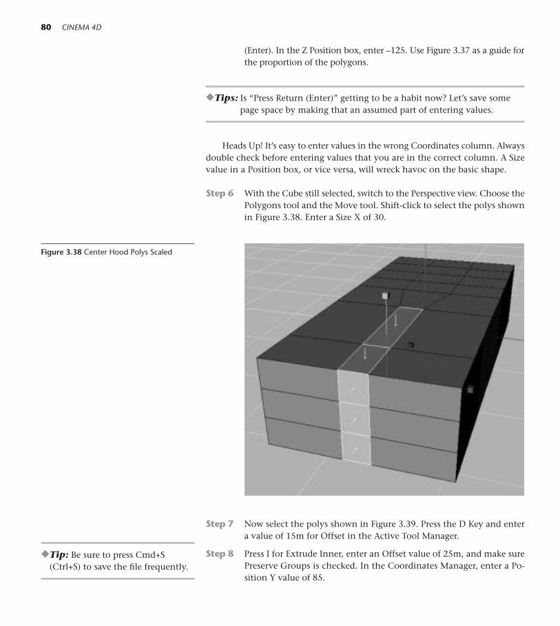
(Enter). In the Z Position box, enter –125. Use Figure 3.37 as a guide forthe proportion of the polygons.
◆Tips: Is “Press Return (Enter)” getting to be a habit now? Let’s save somepage space by making that an assumed part of entering values.
Heads Up! It’s easy to enter values in the wrong Coordinates column. Alwaysdouble check before entering values that you are in the correct column. A Sizevalue in a Position box, or vice versa, will wreck havoc on the basic shape.
Step 6 With the Cube still selected, switch to the Perspective view. Choose thePolygons tool and the Move tool. Shift-click to select the polys shownin Figure 3.38. Enter a Size X of 30.
80 CINEMA 4D
Step 7 Now select the polys shown in Figure 3.39. Press the D Key and entera value of 15m for Offset in the Active Tool Manager.
Step 8 Press I for Extrude Inner, enter an Offset value of 25m, and make surePreserve Groups is checked. In the Coordinates Manager, enter a Po-sition Y value of 85.
Figure 3.38 Center Hood Polys Scaled
◆Tip: Be sure to press Cmd+S(Ctrl+S) to save the file frequently.

3 NURBS Modeling Tools 81
Figure 3.39 Front Hood Polys
Figure 3.40 Front Hood Polys Extruded

Step 9 Select the polys shown in Figure 3.41. Press I for Extrude Inner and inthe Active Tool Manager, enter an Offset of 10. With the same polysstill selected, press the D key and enter an Offset value of –50.
82 CINEMA 4D
Use the green check mark to the right of the HyperNURBS namein the Object manager to turn the HyperNURBS off when you need tosee the polygons clearly.
Step 10 Select the polys shown in Figure 3.44. Press D and drag the mouse leftto right to raise the windshield. Round out the windshield by movingthe polys shown in Figure 3.45 toward the front of the car. Use the redhandle of the Rotate tool to lay the windshield back about –15º. Use thered handle of the Rotate tool to pitch the end polys shown in Figure3.46 over toward the front of the car, and move them slightly forward.
Figure 3.41 Seat Polys
Figure 3.42 Seat Polys Down
Figure 3.43 HyperNURBS Off
Figure 3.44 Starting Polys for Windshield

Step 11 Select the polys shown in Figure 3.47. Enter a Y Position value of 75.
Step 12 Select the top front poly of the windshield shown in Figure 3.48. Usethe green handle of the Move tool to raise it up so the contour of thewindshield is more rounded. Save by choosing File>Save or pressingCmd+S (Ctrl+S).
3 NURBS Modeling Tools 83
Figure 3.45 Front and Center Polys MovedForward Figure 3.46 Windshield Sides Tilted Forward
Figure 3.47 Hood Polys Selected
Figure 3.48 Center of Windshield Raised

Finishing the Front End
Step 1 Select the polys shown in Figure 3.49. Enter a Size Y value of 50.
84 CINEMA 4D
Step 2 Select the polys shown in Figure 3.50. Enter a SizeX value of 150.
Figure 3.49 Front Polys Selection 1
Figure 3.50 Front Polys Selection 2
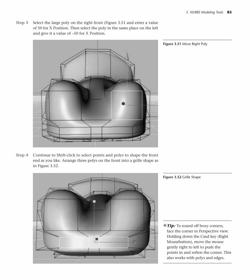
Step 3 Select the large poly on the right front (Figure 3.51 and enter a valueof 50 for X Position. Then select the poly in the same place on the leftand give it a value of –50 for X Position.
3 NURBS Modeling Tools 85
Step 4 Continue to Shift-click to select points and polys to shape the frontend as you like. Arrange three polys on the front into a grille shape asin Figure 3.52.
Figure 3.51 Move Right Poly
Figure 3.52 Grille Shape
◆Tip: To round off boxy corners, face the corner in Perspective view.Holding down the Cmd key (RightMousebutton), move the mousegently right to left to push thepoints in and soften the corner. Thisalso works with polys and edges.

Overriding HyperNURBS Influence
At times in the design process, you’ll want to soften or even eliminate therounding power of the HyperNURBS on the surface. Hold down the period(.) key as you drag on a point, edge, or polygon. The drag distance deter-mines how much the element will ignore the HyperNURBS rounding. Usethis technique when you want sharp points and edges to emerge from anotherwise rounded surface.
86 CINEMA 4D
Figure 3.53 Facing Corner Points
●Springboard! Save the copy ofthe basic Amphibber you have so far(File>Save or Cmd+S/Ctrl+S), thenchoose File>Save As to save somecopies for practicing the pushing,pulling, scaling, and rotating ofpoints, edges, and polys on the meshinside the Body HyperNURBS object.The fine-tuning of the Amphibberdesign is up to you. Remember thatany single point, edge, or poly (orselected sets of these elements) maybe moved, scaled, or rotated to sculptthe surface.
Figure 3.54 Controlling HN Influence

Bringing Up the Rear
Step 1 Working in the Side View, choose the Rectangle selection tool and makesure Only Select Visible Elements is unchecked. Choose the Points tool.
Step 2 Drag the rectangle over the three columns of points on the right, anduse the blue Move handle to lengthen the seat. Then select only the farright column of points and move them back further as in Figure 3.56.
3 NURBS Modeling Tools 87
Step 3 With the end points still selected, scale the setof points to taper the back of the car. Select themiddle poly. Move it out slightly on the Z axisand lift it to round the back contour.
Step 4 Select the polygon on the top of the back sec-tion and pull it up with the Move tool to roundthe top.
Figure 3.55 Elongating the Seat Area
Figure 3.56 Elongating the Trunk Area
Figure 3.57 Back Rounded

Step 5 In the Top view, select the Points shown in Figure 3.58. Scale them closertogether so that the outer polygons become more rectangular. Switchback to Perspective view and the Polygon tool.
88 CINEMA 4D
Figure 3.58 PointsSelected/Points Scaled
Step 6 Select the outer Polygons on the top of the rear section. Press I to Ex-trude Inner, using an Offset value of 15m. Shift-click to select the newouter polys and press D to Extrude them up into tail fins.
With both tail fin polys still selected, scale them on the X axis topull them together. Use the Move, Scale, and Rotate tools to adjust theirshape and angle.
Figure 3.59 Outer Polys
Figure 3.60 Tail fin Bases

All in the Details
Step 1 Select the polys shown in Figure 3.61 and extrude them down insidethe car (but not beyond the bottom). Select the polys shown in Figure3.63 and 3.64. Delete them, since they will not be seen.
3 NURBS Modeling Tools 89
Figure 3.61 Footrest Selected
Figure 3.62 Footrest Dropped
Figure 3.63 Inside Windshield Selected
Figure 3.64 Inside Polys, Isolated View
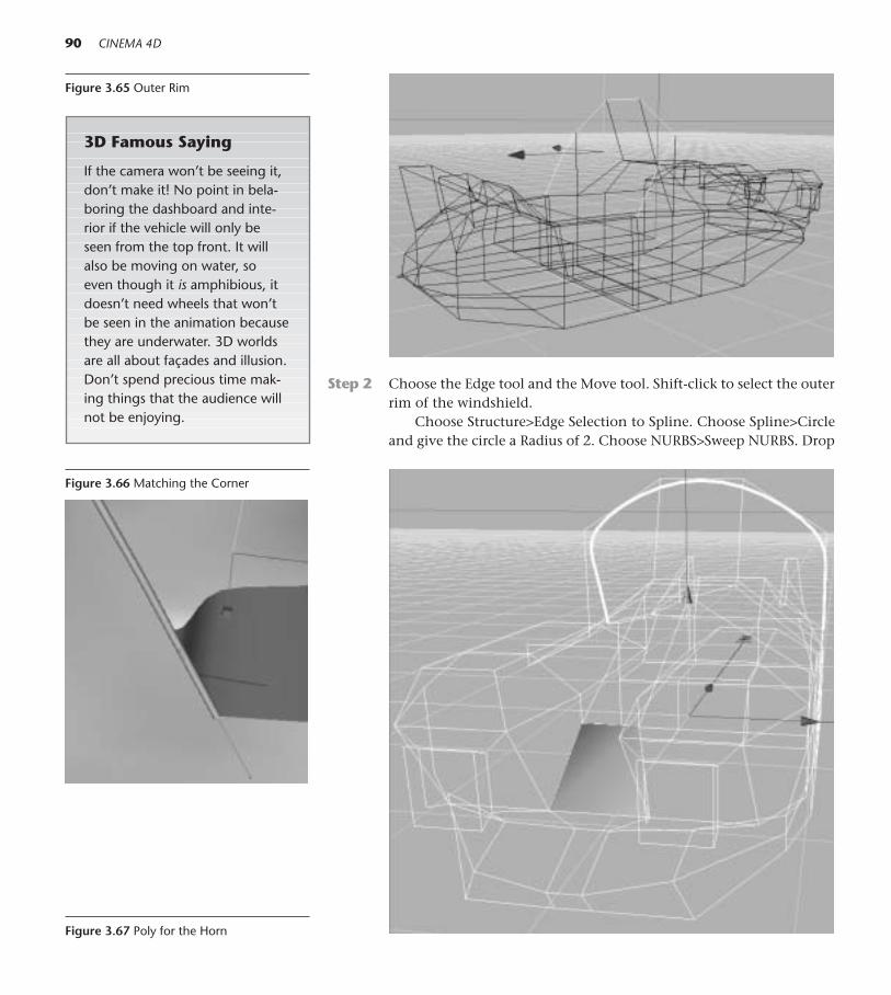
Step 2 Choose the Edge tool and the Move tool. Shift-click to select the outerrim of the windshield.
Choose Structure>Edge Selection to Spline. Choose Spline>Circleand give the circle a Radius of 2. Choose NURBS>Sweep NURBS. Drop
90 CINEMA 4D
Figure 3.65 Outer Rim
3D Famous Saying
If the camera won’t be seeing it,don’t make it! No point in bela-boring the dashboard and inte-rior if the vehicle will only beseen from the top front. It willalso be moving on water, so even though it is amphibious, itdoesn’t need wheels that won’tbe seen in the animation becausethey are underwater. 3D worldsare all about façades and illusion.Don’t spend precious time mak-ing things that the audience willnot be enjoying.
Figure 3.66 Matching the Corner
Figure 3.67 Poly for the Horn
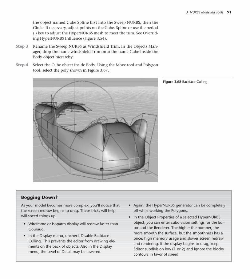
the object named Cube Spline first into the Sweep NURBS, then theCircle. If necessary, adjust points on the Cube. Spline or use the period(.) key to adjust the HyperNURBS mesh to meet the trim. See Overrid-ing HyperNURBS Influence (Figure 3.54).
Step 3 Rename the Sweep NURBS as Windshield Trim. In the Objects Man-ager, drop the name windshield Trim onto the name Cube inside theBody object hierarchy.
Step 4 Select the Cube object inside Body. Using the Move tool and Polygontool, select the poly shown in Figure 3.67.
3 NURBS Modeling Tools 91
Figure 3.68 Backface Culling
Bogging Down?
As your model becomes more complex, you’ll notice thatthe screen redraw begins to drag. These tricks will helpwill speed things up.
• Wireframe or Isoparm display will redraw faster thanGouraud.
• In the Display menu, uncheck Disable BackfaceCulling. This prevents the editor from drawing ele-ments on the back of objects. Also in the Displaymenu, the Level of Detail may be lowered.
• Again, the HyperNURBS generator can be completelyoff while working the Polygons.
• In the Object Properties of a selected HyperNURBSobject, you can enter subdivision settings for the Edi-tor and the Renderer. The higher the number, themore smooth the surface, but the smoothness has aprice: high memory usage and slower screen redrawand rendering. If the display begins to drag, keepEditor subdivision low (1 or 2) and ignore the blockycontours in favor of speed.
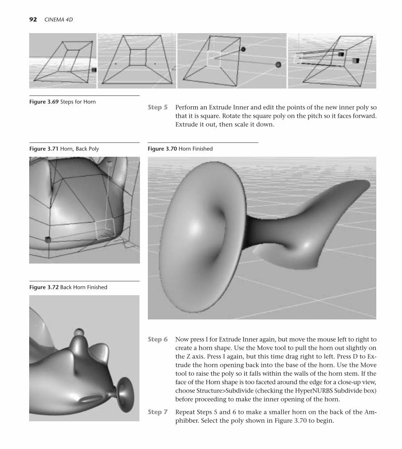
Step 5 Perform an Extrude Inner and edit the points of the new inner poly sothat it is square. Rotate the square poly on the pitch so it faces forward.Extrude it out, then scale it down.
92 CINEMA 4D
Figure 3.69 Steps for Horn
Step 6 Now press I for Extrude Inner again, but move the mouse left to right tocreate a horn shape. Use the Move tool to pull the horn out slightly onthe Z axis. Press I again, but this time drag right to left. Press D to Ex-trude the horn opening back into the base of the horn. Use the Movetool to raise the poly so it falls within the walls of the horn stem. If theface of the Horn shape is too faceted around the edge for a close-up view,choose Structure>Subdivide (checking the HyperNURBS Subdivide box)before proceeding to make the inner opening of the horn.
Step 7 Repeat Steps 5 and 6 to make a smaller horn on the back of the Am-phibber. Select the poly shown in Figure 3.70 to begin.
Figure 3.70 Horn FinishedFigure 3.71 Horn, Back Poly
Figure 3.72 Back Horn Finished

Step 8 Add some shape to the vehicle by pulling out some of the polys on eachside.
Step 9 Select Primitive>Torus and Primitive>Sphere to create a headlight anda rim. Make both objects editable (by pressing the C key), and use theblue Scale tool to flatten them. Position the Torus around the Sphereand Group them, renaming the Group as Headlight. Make a copy of theHeadlight and position both headlights on the front of the Amphibber.You may want to make a more detailed headlight and rim later.
3 NURBS Modeling Tools 93
Figure 3.73 Widening the Body
Figure 3.74 Headlight and Rim
Figure 3.75 Optional Wheels
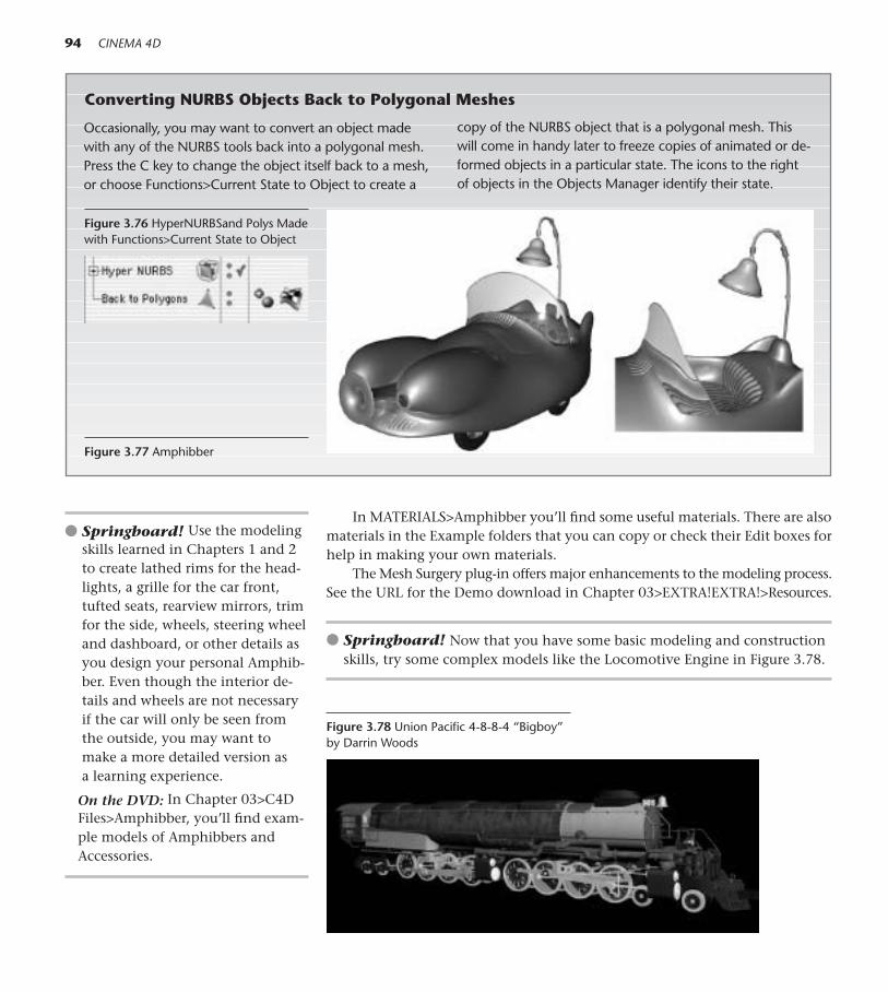
Occasionally, you may want to convert an object madewith any of the NURBS tools back into a polygonal mesh.Press the C key to change the object itself back to a mesh,or choose Functions>Current State to Object to create a
copy of the NURBS object that is a polygonal mesh. Thiswill come in handy later to freeze copies of animated or de-formed objects in a particular state. The icons to the rightof objects in the Objects Manager identify their state.
In MATERIALS>Amphibber you’ll find some useful materials. There are alsomaterials in the Example folders that you can copy or check their Edit boxes forhelp in making your own materials.
The Mesh Surgery plug-in offers major enhancements to the modeling process.See the URL for the Demo download in Chapter 03>EXTRA!EXTRA!>Resources.
● Springboard! Now that you have some basic modeling and constructionskills, try some complex models like the Locomotive Engine in Figure 3.78.
94 CINEMA 4D
Figure 3.76 HyperNURBSand Polys Madewith Functions>Current State to Object
Figure 3.77 Amphibber
Converting NURBS Objects Back to Polygonal Meshes
Figure 3.78 Union Pacific 4-8-8-4 “Bigboy”by Darrin Woods
● Springboard! Use the modelingskills learned in Chapters 1 and 2 to create lathed rims for the head-lights, a grille for the car front,tufted seats, rearview mirrors, trimfor the side, wheels, steering wheeland dashboard, or other details asyou design your personal Amphib-ber. Even though the interior de-tails and wheels are not necessaryif the car will only be seen fromthe outside, you may want tomake a more detailed version asa learning experience.
On the DVD: In Chapter 03>C4DFiles>Amphibber, you’ll find exam-ple models of Amphibbers andAccessories.

T he plot thickens—in this chapter you’ll add modeling helpers to yourtoolbox and enliven your creative repertoire.
Lively Props: Bend and Twist Deformers
Step 1 Choose File>Open and navigate to Chapter 04>C4D Files>PyramidProp>PyramidProp.c4d. Choose File>Save As and save the file as Pyra-mid Prop in your Models folder.
Step 2 From the top toolbar, chooseDeformers>Twist Deforma-tion. Drop the object Twistonto the object Pyramid, sothe deformer is a child of themesh. With Twist selected inthe Objects Manager, enter415m in the middle Size col-umn (Y) under Object Prop-erties. Leave the Mode asLimited. Drag the small blackarrows next to angle up and
4Deformers and Other ModelingHelpers
95
Figure 4.1
Figure 4.2 Twist Deformer
Figure 4.3 Pyramid Twisted

down and see how the twist is affected. You could alternately drag theorange interactive handle to control the twist. Now type 300 in the boxfor Angle in Object Properties.
Step 3 Now choose the Model tool and the Move tool. Make sure all X, Y, andZ locks are free. Move the mouse in the Editor window and see howthe position of the deformer affects the pyramid. Now choose the Ro-tate tool and rotate the red and blue handles. The pyramid could beeasily made to dance back and forth just by keyframing the positionor rotation of the deformer. Press Cmd+Z (Ctrl+Z) to undo the movesand rotations, but leave the Twist at 300º.
Step 4 Choose Deformer>Bend Deformation and drop the object Bend on theobject Pyramid. In the Hierarchy, pick up Bend and reposition it underTwist. It will behave better in this order.
Step 5 Locate the orange interactive handle for the Bend deformer in the ed-itor window. You may need to choose Isoparm display to see it clearly.
Step 6 Choose File>Save As and save several copies to experiment with anima-tion. On your first try, select the word Twist. At frame 0, Command-clickthe word Angle, enter 0 for the value and drag over to Animation>AddKeyframe. Forward the timeline to 50 frames, change the Angle to 300,and set a keyframe. Play the animation. Now select the Bend, and key-frame positive and negative Strength values at different points in time.Go back to frame 0 and choose the Model and Move tools. At 25 and 50frames, move the Twist Deformer cage so the pyramid sways from sideto side and set keyframes by Cmd-clicking (Right-clicking) on the P.Xvalues in the Attributes Manager Coordinates Panel.
As you combine the keyframing of different deformer attributes, position, ro-tation, and scale you’ll find this stiff pyramid is capable of infinite organic moves.Note two adjustments made to the original Pyramid that are enhancing smoothdeformation: 1) Segments for the Pyramid were increased in Object Properties,and 2) A Phong Tag was assigned to smooth the appearance of the surface. Forsmooth motion, you may want to make the animation longer and avoid drasticchanges that are too close together in time.
On the DVD: See Chapter 04>MOVIES/STILLS>Deformers for example movieswith deformers in action. Also see Chapter 04>EXTRA!EXTRA! for more exam-ples of Deformers.
A Lump in the Pipe: Bulge Deformer
Step 1 Choose File>Open and navigate to Chapter 02>C4DFiles>PforPipe onthe DVD. Choose File>Save As and save the file as PforPipeBulge in yourModels folder.
96 CINEMA 4D
Figure 4.4 Bend Deformer
Figure 4.5 Deformer Hierarchy
Figure 4.6 Pyramid Bent and Twisted

4 Deformers and Other Modeling Helpers 97
The Basics of Deformers
• Deformers are made a child of the object you want todeform.
• For successful deformation, the target object needs asufficient number of subdivisions.
• Deformers work on Primitives, Polygonal Meshes,Groups—even Splines.
• To interactively edit a Deformer object, make sureyou have the Deformer selected so you see its bluecage. (The Move, Scale, or Rotate tool and the Modelor Object tool must be chosen for interactive editingwith the orange handle.)
• Deformers usually have to be rotated, scaled, andpositioned to get the desired effect. Use the Move,
Scale, and Rotate tools to transform them like anyother object. These basic transformations can also bekeyframed for animated effects.
• More than one deformer can be placed on an object,and varying the order of deformations in the Hierar-chy will yield different results.
• If you want to temporarily disable a deformer, clickthe green check mark to the right of its name in theObjects Manager.
• To freeze a deformed position as a polygonal mesh,choose Current State to Object from the Functionsmenu.
Changing Animation: Replacing Keyframes or Starting All Over
If there is a red dot next to an attribute, there is an existing keyframealready in place for that value. If you want to change the value at that time,enter the new value and choose Add Keyframe again to replace the formerkeyframe. (In other words, you can’t just change the value.)
Sometimes, especially when you’re learning, animation just doesn’twork out and starting over is the best course of action! Here’s how to deleteanimation:
• Choose the Animation Layout. Click the Timeline tab. If the lock in theupper right corner of the Timeline is unlocked, type Cmd-A (Ctrl-A) andDelete to delete all animation. If the lock is locked, choose Show AllAnimated before selecting all and deleting.
• If you want to remove animation on only one object or attribute, find itsname in the Timeline list. Click the track to the right of the name andpress Delete.
Now you can go back and start animating the object again without the for-mer keyframes getting in the way.
Step 2 Choose Deformer>Bulge and drop the object Bulge onto Polygons in-side the Pipe HyperNURBS object. Select Bulge. In Object Properties,enter 156m for all Size values. Change the mode to Within Box. In the

editor window, position the deformer at the bottom of the pipe andcheck the side view to make sure it is centered around the pipe.
Step 3 At frame 0, click the Coordinates panel and set a P.Y keyframe. Go tothe End of the Animation. Use the green handle of the Move tool to po-sition the deformer cage at the top of the pipe, just under the lip andset another P.Y keyframe.
Step 4 Go back to frame 0. Click the Object panel in the Attributes Manager,and keyframe a value of 0 for Strength. At frame 5, keyframe a Strengthvalue of 100 and at frame 13 keyframe the value at 150. Continue toscrub through the animation, setting keyframes for the Strength valuesonly when needed to adjust the bulge. You may also need to add moreStrength keyframes (reducing the deformer strength and height) atpoints where the inner surface of the pipe is exposed. After setting initialkeyframes, you can always scrub back though the animation and adjustthe deformation to make the surface behave. At the end of the anima-tion, give the Pipe a little squeeze by setting a keyframe of –25 forStrength. Save the file (File>Save or Cmd+S/Ctrl+S).
98 CINEMA 4D
Figure 4.7 Bulge Deformer
Figure 4.8 “Lump” Rising
On the DVD: See Chapter 04>MOVIES/STILLS>Deformers>Pipe.mov.
Boom! Explosion Deformation
Step 1 Choose File>New and save the file as Simple Explosion in your Mod-els folder using File>Save or Cmd+S (Ctrl+S).
Step 2 Choose Primitive>Sphere and enter 100 for Segments.
Step 3 Choose Deformer>Explosion and drop the Explosion deformer ontothe Sphere in the Objects Manager.
Step 4 Select Explosion. At frame 0, Command-click the word Strength in Ob-ject Properties and set a keyframe for a value of 0. At frame 70, changethe Strength value to 100 percent and set a keyframe. Save the file.
Figure 4.9 Explosion Deformer

Preview this animation with Render>Make Preview set on Full Ren-der, then try some variations. Experiment with increasing the Speed,Angle Speed, and End Size and preview the results.
Step 5 Choose File>Revert to Saved.
Step 6 Select Explosion. Let’s reverse the keyframes and make an implosion.At frame 0, enter a new Strength value of 100 percent and set a key-frame. At frame 70, enter 0 percent and set a keyframe. Preview the an-imation.
Step 7 Create a colorful material (a Gradient or Spectral shader would work)to place on the Sphere so the explosion particles have color.
4 Deformers and Other Modeling Helpers 99
On the DVD: See examples in Chapter 04>MOVIES/STILLS>MOVIES. In theChapter 04>EXTRA!EXTRA!>InDepth folder, you’ll find example files for a dif-ferent explosion deformer, ExplosionFX. Study the settings for these examplesto see how this deformer offers a wide range of control over explosions.
Broken Glass: The Shatter Deformer
Step 1 Choose File>Open and navigate to Chapter 04>C4DFiles>Van De Graaffon the DVD. Choose File>Save As and save the file as Shattered Gen-erator. Work in the Front view.
Figure 4.10 Sphere Exploding
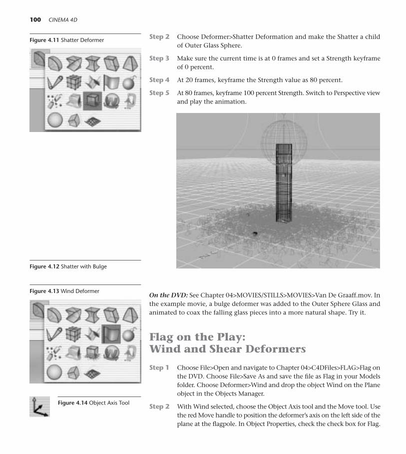
Step 2 Choose Deformer>Shatter Deformation and make the Shatter a childof Outer Glass Sphere.
Step 3 Make sure the current time is at 0 frames and set a Strength keyframeof 0 percent.
Step 4 At 20 frames, keyframe the Strength value as 80 percent.
Step 5 At 80 frames, keyframe 100 percent Strength. Switch to Perspective viewand play the animation.
100 CINEMA 4D
Figure 4.11 Shatter Deformer
On the DVD: See Chapter 04>MOVIES/STILLS>MOVIES>Van De Graaff.mov. Inthe example movie, a bulge deformer was added to the Outer Sphere Glass andanimated to coax the falling glass pieces into a more natural shape. Try it.
Flag on the Play: Wind and Shear Deformers
Step 1 Choose File>Open and navigate to Chapter 04>C4DFiles>FLAG>Flag onthe DVD. Choose File>Save As and save the file as Flag in your Modelsfolder. Choose Deformer>Wind and drop the object Wind on the Planeobject in the Objects Manager.
Step 2 With Wind selected, choose the Object Axis tool and the Move tool. Usethe red Move handle to position the deformer’s axis on the left side of theplane at the flagpole. In Object Properties, check the check box for Flag.
Figure 4.12 Shatter with Bulge
Figure 4.13 Wind Deformer
Figure 4.14 Object Axis Tool

The Flag option holds the Y axis stationary, enabling the left edge of the flagto appear fixed to the flagpole.
Step 3 In Object Properties, start with settings of 40m for Amplitude, 5 for Fre-quency, and 2 in fx and then experiment with changing the settingsone at a time. Attributes may be keyframed to change over time, butkeyframing is not necessary for the deformer to set the flag in motion.Play the animation.
Step 4 Choose Deformer>Shear and place the object Shear on the Plane objectalso. Rotate the deformer 90º on the B (Bank) and position the cage overthe flag in the editor window. Leave the Mode on Limited. Use the or-ange interactive handle of the Shear deformer to droop the right end ofthe flag down. Keyframe some various Strength values at different timesif you want your flag to rise up and down.
Roll The Dice! Boolean Operations
This Hierarchy will be your most complex so far. It will be important to pay at-tention to capital and lowercase letters in the renaming process.
Step 1 Choose File>New and save the file as Dice into your Models folder (File>Save or Cmd+S/Ctrl+S). Work in the Front view and Wireframe Display.
Step 2 Choose Primitive>Cube. In Object Properties, click the Fillet box andenter 20 for Fillet Radius.
Step 3 Choose Primitive>Sphere. Give the sphere a radius of 24. Choose theModel and Move tools. Use the red Move handle to move the sphereto the right, positioning so that its Y axis lines up on the far right edgeof the cube. Rename the sphere as ONE.
4 Deformers and Other Modeling Helpers 101
Figure 4.15 Shear Deformer
Figure 4.16 Flag Flying
Figure 4.17 First Sphere

Step 4 In the Objects Manager, Control-drag three copies of ONE. Rename thecopies as Three 1, Three 2, and Three 3. Use the green Move handle tomove all three up so that their horizontal midline rests on the top edgeof the die. Then use the red Move handle to position them equidistantly,as in Figure 4.18. Select all three and press the G key to group them, nam-ing the group THREE.
Step 5 Now Control-drag a copy of THREE, renaming the copy FOUR. Use thegreen Move handle and move the FOUR group down so the midlinesrest on the bottom edge of the cube. Click the (+) next to Four, and se-lect Three 3. Control-drag a copy of Three 3 and make sure it remainsin the FOUR Group. Rename all the children in FOUR group as Four 1,Four 2, Four 3, and Four 4.
Step 6 Select THREE group. In the Objects Manager, Control-drag a copy andrename the copy as Six. With Six selected, type 90 in the box for BankRotation in the Coordinates Manager and click Apply. Making sure theModel and Move tools are selected, use the green Move handle to movethe copy over and center the sphere axes on the left edge of the die. Thenuse the red handle to center the copy vertically on the left edge.
102 CINEMA 4D
Figure 4.18 Hierarchy and View
Step 7 Switch to the Side View (View 3). Choose a Symmetry Object from thetop menu, and drop Six into it. In Object Properties, set the Mirror Planefor the Symmetry Object as XY. Select Six inside the Symmetry Object
Figure 4.19 SIX Symmetry
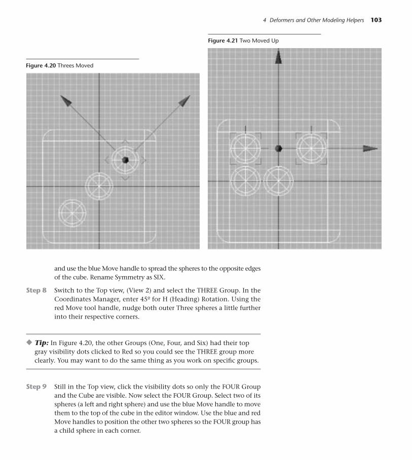
4 Deformers and Other Modeling Helpers 103
Figure 4.20 Threes Moved
and use the blue Move handle to spread the spheres to the opposite edgesof the cube. Rename Symmetry as SIX.
Step 8 Switch to the Top view, (View 2) and select the THREE Group. In theCoordinates Manager, enter 45º for H (Heading) Rotation. Using thered Move tool handle, nudge both outer Three spheres a little furtherinto their respective corners.
◆ Tip: In Figure 4.20, the other Groups (One, Four, and Six) had their topgray visibility dots clicked to Red so you could see the THREE group moreclearly. You may want to do the same thing as you work on specific groups.
Step 9 Still in the Top view, click the visibility dots so only the FOUR Groupand the Cube are visible. Now select the FOUR Group. Select two of itsspheres (a left and right sphere) and use the blue Move handle to movethem to the top of the cube in the editor window. Use the blue and redMove handles to position the other two spheres so the FOUR group hasa child sphere in each corner.
Figure 4.21 Two Moved Up
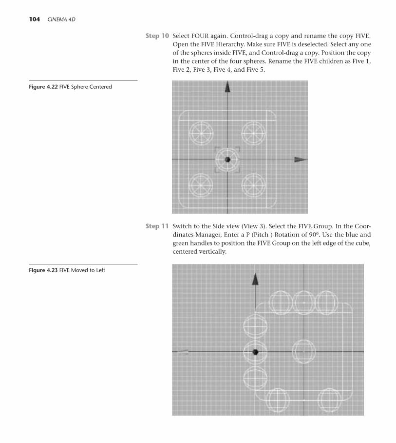
Step 10 Select FOUR again. Control-drag a copy and rename the copy FIVE.Open the FIVE Hierarchy. Make sure FIVE is deselected. Select any oneof the spheres inside FIVE, and Control-drag a copy. Position the copyin the center of the four spheres. Rename the FIVE children as Five 1,Five 2, Five 3, Five 4, and Five 5.
104 CINEMA 4D
Figure 4.22 FIVE Sphere Centered
Step 11 Switch to the Side view (View 3). Select the FIVE Group. In the Coor-dinates Manager, Enter a P (Pitch ) Rotation of 90º. Use the blue andgreen handles to position the FIVE Group on the left edge of the cube,centered vertically.
Figure 4.23 FIVE Moved to Left

Step 12 Select the FOUR Group andmake sure its visibility dot isgray. In the Objects Manager,Control-drag a copy of FOURand rotate the copy 90º onthe Pitch. Rename the Copyas TWO. Use the green andblue move handles to posi-tion and vertically center theTWO Group on the right edgeof the cube.
Step 13 Choose the Front View andmake only the TWO Groupand the Cube visible. Selectthe bottom two spheres (asthey appear in the editor win-dow) and delete them. Re-name the remaining spheresas Two 1 and Two 2. Select the TWO object. Using the Object Axis tooland the Move tool, move the axis back up so it is centered between thetwo spheres.
Step 14 Choose the Model tool and use the blue Move handle to lower thespheres to the vertical midpoint of the die. Choose the Rotate tool anddrag the green rotation axis axis handle until the P value in the Co-ordinates Manager is 45º. Use the red Move handle to slide Two 1 andTwo 2 further into their respective corners.
Step 15 In the Hierarchy, place Groups ONE through SIX in numerical orderjust for good housekeeping, then select them all. Be sure to leave Cubeunselected. Press the G key to group all the spheres, and rename thenew group CUTTERS. Rename Cube as CUTTEE.
Step 16 In the Materials Manager, choose File>New Material. Control-drag acopy of the material thumbnail. Edit the first material to have a colorof red and a Transparency of 25 percent. For the second material, justslide the brightness slider of the default gray to 100 percent for a purewhite. Place the red material on the CUTTEE and the white Materialon the CUTTERS.
Step 17 From the menu over the Objects Manager, choose Objects>Unfold All.Make sure all visibility dots in the entire Hierarchy are returned to gray.In Perspective view, check the sphere positions.
Step 18 From the top toolbar, choose a Boolean Object from the Array palette.Rename the Boolean object as DIE. Drop the object CUTTERS on theobject DIE first, then drop the object CUTTEE onto DIE.
Step 19 Make a copy of DIE so you have a set of dice.
4 Deformers and Other Modeling Helpers 105
Figure 4.24 TWO Axis Centered Figure 4.25 Checking Sphere Positions
Figure 4.26 Boolean Object Icon
Figure 4.27 Finished Dice

Boolean Operations
There are four basic boolean opera-tions. The number of subdivisions inobjects placed in booleans will affectthe smoothness of cut edges. Notonly can groups of objects be usedin booleans (as in the DICE project),but animated objects can be usedinside booleans to create changingforms. If the surface of your booleanobject exhibits some strangeness,take these measures. In version 8.2, choose Plugin>Boole>BooleReplacer. In version 8.5, click theHigh Quality checkbox in ObjectProperties for the Boole.
● Springboard! Who knew simple objects like dice would take so many stepsto make? But the good news is that if you do your archiving homework andkeep your library in good shape you’ll never have to make dice again. Researchall the material “flavors” dice come in by going to Google>Image and typingDice in the search box. Copy this die and try different materials on the copies.You may also want to edit the Fillet on some of the cubes, since some dicehave more rounded edges than others. Save all your Dice.c4d files in a foldernamed Dice Library and place it in in your Models folder.
106 CINEMA 4D
Figure 4.28 Boolean Operations (L>R) A Subtract B,A Union B, A Intersect B,and A Without B
On the DVD: See Chapter 04>MOVIES/STILLS>MOVIES>Animated Boolean.mov.To see how the animation was set up, see Chapter 04>EXAMPLES>BOOLEANS>Animated Boolean.C4D.
A String Of Dice: The Arrange Function
Step 1 Choose File>Open and navigate to Chapter 04>C4D Files>Bakelite Die.Choose File>Save As and save the working copy to your Models folder.
Step 2 Select DIE, and choose Functions>Duplicate. Leave Copies with a valueof 8 and check Generate Instances. The value for X, Y, and Z Move shouldbe 0. Click OK.

Step 3 Rename the Null Object as DICE and select it. From the top menu,choose Functions>Arrange. In the Search For box, press the letters Spand click OK.
Any number of like or different objects can be arranged on a spline usingthis function. The uppermost objects in a Group Hierarchy will occur at the be-ginning of the spline.
4 Deformers and Other Modeling Helpers 107
Figure 4.29 String of Dice
Step 4 With DICE still selected, choose Functions>Randomize. Enter 10 for XMove, and 35 for H, P, and B Rotation. Click OK.
Click the (+) next to DICE. Note that if you wanted to, you couldstill select each DIE and animate their rotation individually.
Great Green Gobs: The Metaball Object
In this tutorial, you’ll use the Metaball object to make great green gobs of grody,grimy grease to plop out when the lump reaches the top of the pipe.
Step 1 Choose File>Open and navigate to Chapter 04>C4D Files>PforPipeBulge.c4d. Choose File>Save As and save a new working copy of the file inyour Models folder. In the top menu, choose Edit>Project Settings. Enter200 in the box for Maximum, press Return (Enter) and close the box.
■ Shortcut: Ctrl+D is the keyboard shortcut for Project Settings.
Step 2 Command-click (or right-click) on Pipe. Drag to New Tag>Display Tag.In the Attributes Manager under Object Properties, click the check boxnext to Use Display Mode and drag down to Isoparms.
Step 3 In the top menu, choose a Metaball Object from the Array Palette.
Step 4 In Object Properties, enter 3 percent for Hull Value. Click the Coordi-nates panel, and enter 0.1 for S.X, S.Y, and S.Z.
Step 5 From the top menu, choose Objects>Polygon Object. In the ObjectsManager, drop the object Polygon into the MetaBall. Select the Poly-gon object.
Figure 4.30 Metaball Object Icon
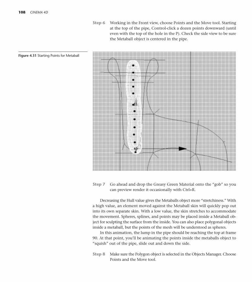
Step 6 Working in the Front view, choose Points and the Move tool. Startingat the top of the pipe, Control-click a dozen points downward (untileven with the top of the hole in the P). Check the side view to be surethe Metaball object is centered in the pipe.
108 CINEMA 4D
Figure 4.31 Starting Points for Metaball
Step 7 Go ahead and drop the Greasy Green Material onto the “gob” so youcan preview render it occasionally with Ctrl+R.
Decreasing the Hull value gives the Metaballs object more “stretchiness.” Witha high value, an element moved against the Metaball skin will quickly pop outinto its own separate skin. With a low value, the skin stretches to accommodatethe movement. Spheres, splines, and points may be placed inside a Metaball ob-ject for sculpting the surface from the inside. You can also place polygonal objectsinside a metaball, but the points of the mesh will be understood as spheres.
In this animation, the lump in the pipe should be reaching the top at frame90. At that point, you’ll be animating the points inside the metaballs object to“squish” out of the pipe, slide out and down the side.
Step 8 Make sure the Polygon object is selected in the Objects Manager. ChoosePoints and the Move tool.

Step 9 In the Animation Toolbar, enable only Point Level Animation. At frame88, press the record keyframe button or press F9 to set a keyframe for thecurrent position for the points.
Step 10 Drag the current time to frame 91. Press F5 to work in All Views so youcan keep the Metaball within the edges of the pipe as you sculpt the sur-face. In order to see the points inside the Metaball hull, use the 2 keywith the mouse to move in close. Using the Move tool, select and movepoints upward to reshape the gob so that it is widening and coming upout of the pipe. Set a keyframe.
Step 11 Drag the current time forward four or five frames at a time, stopping eachtime to move points up and out. Don’t forget to keyframe the change instate each time you move points. Test render with Ctrl+R once in a whileto make sure things are looking good.
●Springboard! This kind of animation takes patience. You may have topractice this a few times to get a smooth creepy-crawly motion. While youcan Shift-click to select groups of points to move larger sections of the form,and speed up the process, the “too much, too fast” approach may be coun-terproductive. In the long run, the more points that are moved independ-ently over small distances and the closer the frames are together, the moreorganic your grease will be. Try making some other Metaball forms usingspheres, splines, and polygonal objects as children.
On the DVD: See Chapter 04>MOVIES/STILLS/MOVIES/Great Green Gobs.mov.
4 Deformers and Other Modeling Helpers 109
Figure 4.32 Metaball Creeping

This Page Intentionally Left Blank
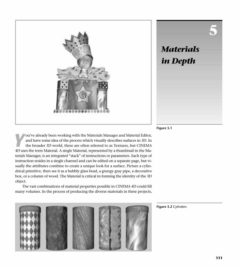
Y ou’ve already been working with the Materials Manager and Material Editor,and have some idea of the process which visually describes surfaces in 3D. Inthe broader 3D world, these are often referred to as Textures, but CINEMA
4D uses the term Material. A single Material, represented by a thumbnail in the Ma-terials Manager, is an integrated “stack” of instructions or parameters. Each type ofinstruction resides in a single channel and can be edited on a separate page, but vi-sually the attributes combine to create a unique look for a surface. Picture a cylin-drical primitive, then see it as a bubbly glass bead, a grungy gray pipe, a decorativebox, or a column of wood. The Material is critical in forming the identity of the 3Dobject.
The vast combinations of material properties possible in CINEMA 4D could fillmany volumes. In the process of producing the diverse materials in these projects,
5Materials in Depth
111
Figure 5.1
Figure 5.2 Cylinders

112 CINEMA 4D
Editing Material Parameters
Double-click on a thumbnail in the Materials Manager to edit parameters in the Material Editor. In the Material Editor, select the parameter you want towork with (the gray band denotes selection) and edit the values and sliders on its page. You can also single-click the thumbnail to edit parameters in theAttributes Manager. Click the Parameter Page you want to edit at the top of the Attributes Manager.
Figure 5.3 Material Thumbnails
Figure 5.4 Material Editor Figure 5.5 Attributes Manager
you’ll gain understanding of the different types of materials available in CINEMA4D and the general process of how they can be crafted. Exploring all the infinitecombinations will take a lifetime.
Alternately, procedural textures called Shaders can be used to visually define achannel. Shaders are mathematically calculated textures, and because they are notbased on pixels, they appear the same at any proximity. 2D Shaders remain on theobject surface, but 3D Shaders apply to the object volumetrically.
The most sophisticated Shaders, the BhodiNUT Smells Like Almonds, arecomplex and powerful shading engines that offer intense editability. Thesethinking shaders calculate the look of the material based on other factors in thescene. The serious 3D artist will avoid the temptation to use these inherentlybeautiful shaders with clip art ease but rather will want to spend hours explor-ing the power of these engines for unique looks.
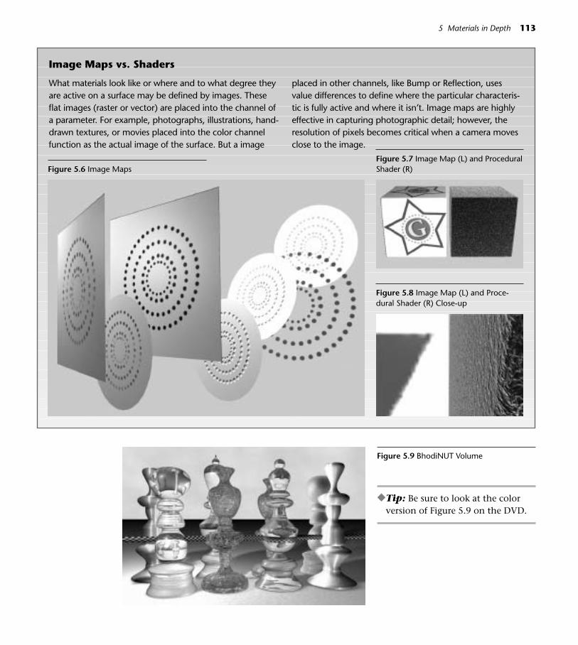
5 Materials in Depth 113
Image Maps vs. Shaders
What materials look like or where and to what degree theyare active on a surface may be defined by images. Theseflat images (raster or vector) are placed into the channel ofa parameter. For example, photographs, illustrations, hand-drawn textures, or movies placed into the color channelfunction as the actual image of the surface. But a image
placed in other channels, like Bump or Reflection, usesvalue differences to define where the particular characteris-tic is fully active and where it isn’t. Image maps are highlyeffective in capturing photographic detail; however, theresolution of pixels becomes critical when a camera movesclose to the image.
Figure 5.6 Image MapsFigure 5.7 Image Map (L) and ProceduralShader (R)
Figure 5.8 Image Map (L) and Proce-dural Shader (R) Close-up
Figure 5.9 BhodiNUT Volume
◆Tip: Be sure to look at the colorversion of Figure 5.9 on the DVD.
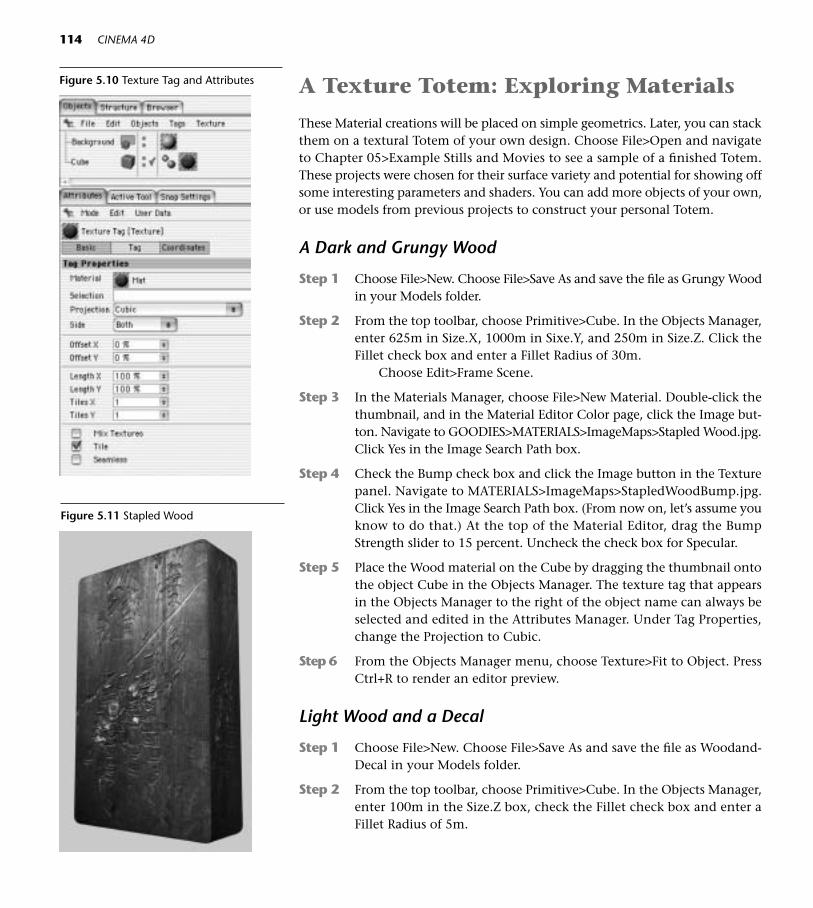
114 CINEMA 4D
A Texture Totem: Exploring Materials
These Material creations will be placed on simple geometrics. Later, you can stackthem on a textural Totem of your own design. Choose File>Open and navigateto Chapter 05>Example Stills and Movies to see a sample of a finished Totem.These projects were chosen for their surface variety and potential for showing offsome interesting parameters and shaders. You can add more objects of your own,or use models from previous projects to construct your personal Totem.
A Dark and Grungy Wood
Step 1 Choose File>New. Choose File>Save As and save the file as Grungy Woodin your Models folder.
Step 2 From the top toolbar, choose Primitive>Cube. In the Objects Manager,enter 625m in Size.X, 1000m in Sixe.Y, and 250m in Size.Z. Click theFillet check box and enter a Fillet Radius of 30m.
Choose Edit>Frame Scene.
Step 3 In the Materials Manager, choose File>New Material. Double-click thethumbnail, and in the Material Editor Color page, click the Image but-ton. Navigate to GOODIES>MATERIALS>ImageMaps>Stapled Wood.jpg.Click Yes in the Image Search Path box.
Step 4 Check the Bump check box and click the Image button in the Texturepanel. Navigate to MATERIALS>ImageMaps>StapledWoodBump.jpg.Click Yes in the Image Search Path box. (From now on, let’s assume youknow to do that.) At the top of the Material Editor, drag the BumpStrength slider to 15 percent. Uncheck the check box for Specular.
Step 5 Place the Wood material on the Cube by dragging the thumbnail ontothe object Cube in the Objects Manager. The texture tag that appearsin the Objects Manager to the right of the object name can always beselected and edited in the Attributes Manager. Under Tag Properties,change the Projection to Cubic.
Step 6 From the Objects Manager menu, choose Texture>Fit to Object. PressCtrl+R to render an editor preview.
Light Wood and a Decal
Step 1 Choose File>New. Choose File>Save As and save the file as Woodand-Decal in your Models folder.
Step 2 From the top toolbar, choose Primitive>Cube. In the Objects Manager,enter 100m in the Size.Z box, check the Fillet check box and enter aFillet Radius of 5m.
Figure 5.10 Texture Tag and Attributes
Figure 5.11 Stapled Wood

5 Materials in Depth 115
Step 3 In the Materials Manager, choose File>New Material. Double click thethumbnail, and in the Material Editor Color pane, click the Image but-ton. Navigate to GOODIES>MATERIALS>ImageMaps>Wood.jpg.
Step 4 Check the Bump check box and click the Image button in the Texturepanel. Navigate to GOODIES>MATERIALS>ImageMaps>WoodBump.jpg. At the top of the Material Editor, drag the Bump Strength slider to40 percent. Uncheck the check box for Specular. Double-click the nameof the Material to rename it as Wood.
The Specular highlight is a shininess that occurs where lights hit the objectand create a highlight. Unless wood has a layer of varnish or shellac, it will needlittle or no specularity. These woods are rough and natural, so we are turning theSpecular channel off.
Step 5 In the Materials Manager, Control-drag a copy of the Wood materialthumbnail. On the Color pane, click the small black arrow to the rightof the Image button and drag to Copy Channel. Click the small blackarrow once again and drag to BhodiNUT Channel/Bhodinut Fusion.Click the Edit button in the Texture Panel. 8.5 Update Instead of choosing BhodiNUT Channel>BhodiNUT Fu-sion, just click the small black triangle and choose Fusion. Click theword Fusion to edit the shader as in Steps 6 through 8.
The BhodiNUT Fusion shader is an energetic workhorse for blending mate-rials. Its blending modes (yes, like Photoshop) and masking let you choose howand in what areas the materials mix. This shader can also be used to mask off aparticular area of any other shader.
Step 6 In the Smells Like Almonds editor window, locate the Base Channel atthe bottom of the pane. Click the small black arrow at the right of theempty Image box and choose Paste Channel.
Step 7 At the top of the SLA box, click the Image button in the Blend Channelpane. Navigate to GOODIES>MATERIALS>ImageMaps>Star Decal.jpg.
Step 8 Now at the bottom of the left pane of the SLA window, click the checkbox for Use Mask. Then, in the Mask Channel pane to the middle right,click the Image button and navigate to GOODIES>MATERIALS>ImageMaps>StarDecal Alpha.jpg. Experiment with the Blend slider in the leftpane to get the level of “fadedness” you want the decal to have.
Step 9 Name the second Material as Decal.
You may be wondering why you created two materials. Because we only wantthe decal on one side, we will use a selection to limit the Material with the Decalonly to the front of the cube. Notice the cracks in the decal, and study the StarDecal Alpha file. They were created in Photoshop by incorporating a photo of
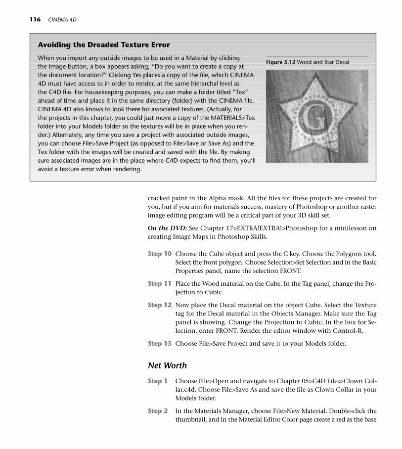
116 CINEMA 4D
Avoiding the Dreaded Texture Error
When you import any outside images to be used in a Material by clicking the Image button, a box appears asking, “Do you want to create a copy at the document location?” Clicking Yes places a copy of the file, which CINEMA 4D must have access to in order to render, at the same hierarchal level as the C4D file. For housekeeping purposes, you can make a folder titled “Tex” ahead of time and place it in the same directory (folder) with the CINEMA file.CINEMA 4D also knows to look there for associated textures. (Actually, for the projects in this chapter, you could just move a copy of the MATERIALS>Texfolder into your Models folder so the textures will be in place when you ren-der.) Alternately, any time you save a project with associated outside images,you can choose File>Save Project (as opposed to File>Save or Save As) and theTex folder with the images will be created and saved with the file. By makingsure associated images are in the place where C4D expects to find them, you’llavoid a texture error when rendering.
Figure 5.12 Wood and Star Decal
cracked paint in the Alpha mask. All the files for these projects are created foryou, but if you aim for materials success, mastery of Photoshop or another rasterimage editing program will be a critical part of your 3D skill set.
On the DVD: See Chapter 17>EXTRA!EXTRA!>Photoshop for a minilesson oncreating Image Maps in Photoshop Skills.
Step 10 Choose the Cube object and press the C key. Choose the Polygons tool.Select the front polygon. Choose Selection>Set Selection and in the BasicProperties panel, name the selection FRONT.
Step 11 Place the Wood material on the Cube. In the Tag panel, change the Pro-jection to Cubic.
Step 12 Now place the Decal material on the object Cube. Select the Texturetag for the Decal material in the Objects Manager. Make sure the Tagpanel is showing. Change the Projection to Cubic. In the box for Se-lection, enter FRONT. Render the editor window with Control-R.
Step 13 Choose File>Save Project and save it to your Models folder.
Net Worth
Step 1 Choose File>Open and navigate to Chapter 05>C4D Files>Clown Col-lar.c4d. Choose File>Save As and save the file as Clown Collar in yourModels folder.
Step 2 In the Materials Manager, choose File>New Material. Double-click thethumbnail, and in the Material Editor Color page create a red as the base

5 Materials in Depth 117
Figure 5.13 Clown Collar
color. Activate the Alpha parameter. Click on the small black arrow nextto the Image button, and drag down to BhodiNUT Channel>BhodiNUTTiles.8.5 Update After clicking the small black arrow on the left, choose Sur-faces>Tiles instead of BhodiNUT Channel>BhodiNUT Tiles.
Step 3 Click the Edit button, and in the SLA window change Tile Color 1 andTile Color 2 to white. Change the Global Scale to 10 percent and enter0.5 for Grout Width. Back in the Material Editor, check the check boxfor Invert in the Texture panel. Name the material Net.8.5 Update Click the word Tiles to edit in the Material Editor as inStep 3.
Step 4 Create a new material thumbnail. On the Color page create a light pur-ple. Check on the Reflection parameter, click the black arrow next toImage, and choose BhodiNUT Channel>BhodiNUT Tiles.8.5 Update Choose Surfaces>Tiles instead of BhodiNUT Channel>BhodiNUT Tiles.
Step 5 Click Edit and in the SLA editor, choose Circles 1. Edit Tile Color 1 to beblack and Tile Color 2 to be white. Change Global Scale to 80 percent.8.5 Update Click the word Tiles to edit in the Material Editor as inStep 3.
Step 6 Back in the Material Editor, click the small black arrow again and dragto Copy Channel. Activate the Alpha parameter page. Click the blackarrow again and drag to choose Paste Channel.
Step 7 Activate Specular Color. Edit the color to be a bright pink. Name thematerial Mylar Dot.
Step 8 Place Both Materials on the Clown Collar, Net first and then Mylar Dot.

118 CINEMA 4D
This technique is useful for all kinds of materials with open detail like lace,screens, or metal with decorative openwork. The global scale of the pattern (asin the Square pattern used to make the net) may need to be adjusted as the cam-era is closer or farther away. The Alpha channel determines in what areas thesurface is 100 percent there, visible with some percentage of fade, or not thereat all. Use materials whenever you can to save modeling cutout detail.
Fake Façades
Complex organic surfaces can be faked by placing the right image maps on flatgeometry. The theater-set mentality of creating “flats” to give the illusion of three-dimensional structures translates well to digital worlds. Sometimes it’s only thefront that counts.
Step 1 Choose File>Open and navigate to Chapter 05>C4D Files>Fake Fa-cade.c4d. Choose File>Save As and save the file as Fake Column inyour Models folder.
Take a minute to look at this 3D Model. Choose Objects>ObjectInformation. Whoa—how’s that for a low poly count?
Step 2 In the Materials Manager, choose File>New Material. Double-click thethumbnail. On the Color pane click the Image button and navigate toGOODIES>MATERIALS>ImageMaps>Column.jpg.
Step 3 Check on the Bump channel and import the ColumnBump.jpg fromthe same location.
Step 4 Activate the Alpha channel, and import ColumnAlpha.jpg.
Step 5 Place the Material on the name Polygon in the Objects Manager.Render a preview of the Editor with Ctrl+R. All that richness is com-
municated by one little polygon mapped with a well-lit photograph.The lesson here is to use illusion whenever you can to economize onpolygons and save modeling time.
Decorative Glass
This glass is made with channel shaders and is edited to have interesting colorqualities. After you’ve made this version, copy the file and experiment with yourown changes to the parameter pages.
Figure 5.15 Fake Facade
Figure 5.14 Other Alpha Examples

Step 1 Choose File>Open and navigate to Chapter 05>C4D Files>GlassPalladian.c4d. Choose File>Save As and save the file as Glass Palladian in yourModels folder.
Step 2 In the Materials Manager, choose File>New Material. Double-click thethumbnail, and in the Material Editor Color page choose a light warmgreen as the base color. (R 215, G215, B65, and 85 percent Brightnesswill work.)
Step 3 Activate the Transparency parameter. Edit the Color rectangle to be abright yellow (255, 255, 0) and set the Brightness to 85 percent. In thetop right corner, set the Refraction value as 1.1. Check the check boxfor Fresnel. Choose Shader>Turbulance from the Shader list. 8.5 Update The Refraction menu has been moved slightly down andto the left. Instead of Shader>Turbulence, choose Surfaces>Simple Tur-bulence.
Step 4 Turn on the Reflection channel.
Step 5 In the Bump channel, click the black arrow and choose Shader>Tur-bulence. 8.5 Update Instead, choose Surfaces>Simple Turbulence.
Step 6 In the Specular channel, enter 50 percent for Width and 20 percent forHeight.
Step 7 Activate Specular Color and edit the color box to be shocking pink. (255,0, 246 with a Brightness of 150 percent.) Place the material on the Pal-ladian and render the editor with Control-R.
Photo Face
Photos or illustrations can be wrapped around models. The Photoshop tutorialon the DVD will show you how to prepare Image Maps for Spherical or Cylin-drical projection.
Step 1 Choose File>New and save the file as Littlehead.c4d. into your Modelsfolder (File>Save or Cmd+S/Ctrl+S).
Step 2 Choose Primitive>Sphere.
Step 3 In the Materials Manager, choose File>New Material. Double-click thethumbnail, and in the Material Editor Color pane click the Image but-ton. Navigate to GOODIES>MATERIALS>ImageMaps>Littleface.c4D.
Step 4 Activate the Bump channel and navigate to MATERIALS>ImageMaps>Littleface Bump.c4D to import the image map for the Bump.
Step 5 Place the material on the sphere.
5 Materials in Depth 119
Figure 5.16 Glass Palladian
Figure 5.17 Littlehead
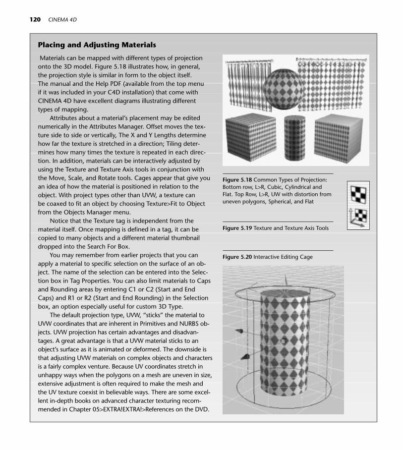
120 CINEMA 4D
Placing and Adjusting Materials
Materials can be mapped with different types of projectiononto the 3D model. Figure 5.18 illustrates how, in general, the projection style is similar in form to the object itself. The manual and the Help PDF (available from the top menuif it was included in your C4D installation) that come withCINEMA 4D have excellent diagrams illustrating different types of mapping.
Attributes about a material’s placement may be editednumerically in the Attributes Manager. Offset moves the tex-ture side to side or vertically, The X and Y Lengths determinehow far the texture is stretched in a direction; Tiling deter-mines how many times the texture is repeated in each direc-tion. In addition, materials can be interactively adjusted byusing the Texture and Texture Axis tools in conjunction withthe Move, Scale, and Rotate tools. Cages appear that give youan idea of how the material is positioned in relation to the object. With project types other than UVW, a texture can be coaxed to fit an object by choosing Texture>Fit to Object from the Objects Manager menu.
Notice that the Texture tag is independent from the material itself. Once mapping is defined in a tag, it can becopied to many objects and a different material thumbnaildropped into the Search For Box.
You may remember from earlier projects that you canapply a material to specific selection on the surface of an ob-ject. The name of the selection can be entered into the Selec-tion box in Tag Properties. You can also limit materials to Capsand Rounding areas by entering C1 or C2 (Start and EndCaps) and R1 or R2 (Start and End Rounding) in the Selectionbox, an option especially useful for custom 3D Type.
The default projection type, UVW, “sticks” the material toUVW coordinates that are inherent in Primitives and NURBS ob-jects. UVW projection has certain advantages and disadvan-tages. A great advantage is that a UVW material sticks to anobject’s surface as it is animated or deformed. The downside isthat adjusting UVW materials on complex objects and charactersis a fairly complex venture. Because UV coordinates stretch inunhappy ways when the polygons on a mesh are uneven in size,extensive adjustment is often required to make the mesh andthe UV texture coexist in believable ways. There are some excel-lent in-depth books on advanced character texturing recom-mended in Chapter 05>EXTRA!EXTRA!>References on the DVD.
Figure 5.20 Interactive Editing Cage
Figure 5.18 Common Types of Projection:Bottom row, L>R, Cubic, Cylindrical andFlat. Top Row, L>R, UW with distortion fromuneven polygons, Spherical, and Flat
Figure 5.19 Texture and Texture Axis Tools

5 Materials in Depth 121
Glitter and Sequin Star
These challenging materials make use of image maps to isolate small points ofsparkle.
Step 1 Choose File>Open and navigate to Chapter 05>C4D Files>Glitter-Star.c4d. Choose File>Save As and save the file as GlitterStar in yourModels folder.
Step 2 In the Materials Manager, choose File>New Material. On the MaterialEditor Color pane click the black arrow next to Image and drag to BhodiNUT Channel>BhodiNUT Fusion. Click Edit. In the Blend channel, nav-igate to GOODIES>MATERIALS>ImageMaps>AFewSequins.jpg. In theleft panel of the SLA window, click Use Mask. In the Mask channel, im-port A FewSequinsAlpha.jpg from the same location. In the Base chan-nel, place Glitter.jpg from the same folder. Click OK.8.5 Update Click the small black arrow on the left and choose Fusioninstead of BhodiNUT Channel>BhodiNUT Fusion. Click on Fusion toedit the shader as in Step 2, but working in the Material Editor.
Step 3 Activate Reflection and import AFewSequinsReflect.jpg from the samelocation.
Step 4 Turn on Bump and import the GlitterBump.jpg from the same folder.
Step 5 Edit the Specular channel to have a Width of 25 percent and a Heightof 60 percent.
Step 6 Place the Material on the Star with Cubic projection. In the Objects Man-ager, choose Texture>Fit to Object. Click Yes when asked to include sub-objects. Use the Texture tool and the Move and Scale tools to adjust thetexture so that none of the sequins slide off the edge of the star.
Figure 5.21 Glitter and Sequin Star
Pushing the Limits: Grunge and Sparkle
The ability of 3D applications to create mechanically perfect objects can beyour worst enemy as an artist. On one end, perfection, you’ll be spendingmany hours making surfaces look like they live in the real world. The diffu-sion channel is the main workhorse for dirtying, scratching, and otherwisegrunging surfaces so they look like they have been through the vigors of life.The new Dirt shader in version 8.5 goes beyond the ability to selectivelydarken a material. It actually goes down in the cracks and crevices like thereal thing.
On the other end of boringly normal, you may also be working hard to enhance surfaces toward supercharged or surreal color and high levels ofsparkle, glitz, and “bling, bling.” Selectively mapped points of reflection andthe highlights and glows you’ll explore later in the Advanced RenderingChapter will help you push the limits.

Embossed Gold
So many nuances on a metal surface! Image maps thoughtfully placed emulatethe real thing.
Step 1 Choose File>Open and navigate to Chapter 05>C4D Files>Metal-Crown.c4d. Choose File>Save As and save the file as Metal Crown inyour Models folder.
Step 2 In the Materials Manager, choose File>New Material. On the MaterialEditor Color pane choose a light warm gold as the base color. (R 255,G 248, B 123, and 100 percent Brightness will work.)
Step 3 Activate the Diffusion channel, click the small black arrow and chooseShader>Turbulence. Click the Edit button. In the Attributes Manager,leave U Frequency to 1 and change the V Frequency to 2. Reduce theDiffusion mix to 75 percent.8.5 Update Instead of Shader>TurbulAnce, choose Surfaces>SimpleTurbulAnce.
Step 4 Click on the Reflection parameter. Turn on the Bump channel, and clickthe Image button. Navigate to MATERIALS>ImageMaps>CrownInvert-edMap.jpg. From the Shader manu, choose Copy Channel.8.5 Update Copy channel is now accessed from the small black arrowon the left.
Step 5 Edit the Specular page to have 40 percent width, 80 percent Height, andFalloff 5 percent. Turn on the Specular Color pane and edit the color tobe a light green. Name the material Gold 1.
Step 6 Create a second material. On the Color pane, choose a light gold with125 percent Brightness.
Step 7 Activate the Bump and Alpha channels, and choose Paste Channel toplace Crown Inverted Map.jpg into both. In the Alpha pane, check thecheck box for Soft. Name this material Gold 2.
Step 8 Place both materials on the crown, making sure Gold 2 is on the far right.Shift-click to select both material tags, and in the Attributes Manager,drag the Offset X value to align the tallest part of the embossed designwith the tallest part of the crown (–25 Offset X).
Step 9 In the Materials Manager, Control-drag a copy of Gold 1 and rename itPlain Gold. Delete the image map from the Reflection pane, and uncheckthe Bump channel. Place Plain Gold on the Bottom and Top Rims of thecrown.
Punched Paper
Step 1 Choose File>Open and navigate to Chapter 05>C4D Files>PaperCrowns.c4d. Choose File>Save As and save the file as Paper Crowns in your Mod-els folder.
122 CINEMA 4D
Figure 5.22 Embossed Crown

5 Materials in Depth 123
Step 2 In the Materials Manager, choose File>New Material. On the MaterialEditor Color pane create a medium red. Place this material on the InnerCrown and the Rim.
Step 3 Create another material and edit the color to be a medium purple.
Step 4 Turn on the Bump channel and place the shader of your choice in theImage box to add some embossed texture to the paper.
Step 5 Give the Specular channel a Width and Height of 50 percent. Turn on theSpecular Color chaActivate the Alpha channel, and navigate to GOOD-IES>MATERIALS>ImageMaps>Harlequin Map.jpg. Place this materialon the Outer Crown. Choose Cylindrical mapping.
Step 7 From the menu over the Objects Manager, choose Texture>Fit to Object.In the Attributes Manager Tag Properties, enter 2 in the Tiles X box.
Step 8 Choose the Texture tool and the Move tool. Drag the Move tool to ad-just the position of the harlequin holes. The holes should be as highas possible without cutting into the top edge of the crown.
Multicolor Magic
Choose File>Open and navigate to Chapter 05>EXAMPLES>MulticolorMagic.c4d. Investigate this Library of multicolor embellishments by browsing throughthe material parameters. Study the placement styles by clicking the Texture tags.Some of these materials use unorthodox texture placement to get totally different
Figure 5.24 Multicolor Magic
Figure 5.23 Paper Crowns
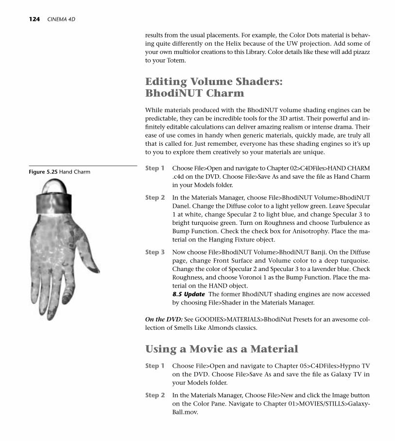
124 CINEMA 4D
results from the usual placements. For example, the Color Dots material is behav-ing quite differently on the Helix because of the UW projection. Add some ofyour own multiolor creations to this Library. Color details like these will add pizazzto your Totem.
Editing Volume Shaders: BhodiNUT CharmWhile materials produced with the BhodiNUT volume shading engines can bepredictable, they can be incredible tools for the 3D artist. Their powerful and in-finitely editable calculations can deliver amazing realism or intense drama. Theirease of use comes in handy when generic materials, quickly made, are truly allthat is called for. Just remember, everyone has these shading engines so it’s upto you to explore them creatively so your materials are unique.
Step 1 Choose File>Open and navigate to Chapter 02>C4DFiles>HAND CHARM.c4d on the DVD. Choose File>Save As and save the file as Hand Charmin your Models folder.
Step 2 In the Materials Manager, choose File>BhodiNUT Volume>BhodiNUTDanel. Change the Diffuse color to a light yellow green. Leave Specular1 at white, change Specular 2 to light blue, and change Specular 3 tobright turquoise green. Turn on Roughness and choose Turbulence asBump Function. Check the check box for Anisotrophy. Place the ma-terial on the Hanging Fixture object.
Step 3 Now choose File>BhodiNUT Volume>BhodiNUT Banji. On the Diffusepage, change Front Surface and Volume color to a deep turquoise.Change the color of Specular 2 and Specular 3 to a lavender blue. CheckRoughness, and choose Voronoi 1 as the Bump Function. Place the ma-terial on the HAND object.8.5 Update The former BhodiNUT shading engines are now accessedby choosing File>Shader in the Materials Manager.
On the DVD: See GOODIES>MATERIALS>BhodiNut Presets for an awesome col-lection of Smells Like Almonds classics.
Using a Movie as a MaterialStep 1 Choose File>Open and navigate to Chapter 05>C4DFiles>Hypno TV
on the DVD. Choose File>Save As and save the file as Galaxy TV inyour Models folder.
Step 2 In the Materials Manager, Choose File>New and click the Image buttonon the Color Pane. Navigate to Chapter 01>MOVIES/STILLS>Galaxy-Ball.mov.
Figure 5.25 Hand Charm

5 Materials in Depth 125
Step 3 Click the Edit button, and in the Movie Data box enter 90 in the Tobox. Click OK.8.5 Update Click on the words GALAXY BALL.mov, and click the An-imation panel to edit as in Step 3.
Step 4 Choose Objects>Unfold All from the Objects Manager menu. Drop theGalaxy Ball movie Material on the Disc object.
When you render the Hypno TV animation, the Galaxy movie will play onthe TV screen.
Animating Materials
In this project, you’ll learn how to animate colors to change over time and copyanimation tracks from one object to another.
Step 1 Choose File>Open and navigate to Chapter 05>C4DFiles>StringOfHandson the DVD. Choose File>Save As and save the file as String of Hands inyour Models folder. Materials have already been placed on each hand.
Step 2 Open the Animation Layout from the left palette.
Step 3 Open the hierarchy for Hand 1 in the Objects Manager and drag thered texture tag to the right of the Cube object across the editor win-dow and into the empty left area of the Timeline Window.
Step 4 Command-click (or right-click) on the name Tag:Texture in the Time-line window, and drag to New Track>Parameter>Material. On the new
Figure 5.27Hypno TV
Figure 5.28Choosing theAnimationLayout
Batch Rendering
CINEMA 4D will work while you snooze. Long renders(which you may certainly run into when the BhodiNUTengines start calculating) can be placed in the Batch Renderqueue. For any given file, set up all your render settingsahead of time. Save the file with Save Project. Then, withany C4D file open, choose Render>Batch. Click the Jobbutton, and navigate to each file you want to render. Youcan set up as many as ten files to render overnight, but becertain you set up all the render settings and enter differenttitles for the files.
Figure 5.26 Batch Rendering

126 CINEMA 4D
track that appears in the Timeline window, Control-click on the trackat 0 frames to create a keyframe. Note that the Attributes Manager (KeyProperties) now shows information on the single key and the colorcurrently in the Material box is Red.
Figure 5.30 Key Properties
Step 5 Go to 25 frames and Control-click a new key on the track. Click theMaterials tab next to the Objects Manager Tab to open the MaterialsManager. Drag the thumbnail for Blue into the Material box under KeyProperties (down in the Attributes Manager).
Step 6 Control-click new keys every 25 frames across the Timeline, droppinga different color from the Materials manager into the Attributes Man-ager Material box for each key. If you need to check or adjust the orderof colors, just click back on each key and see what color name is in theMaterial box.
Play the animation by pressing the Play Button or the F8 key and watchHand 1. The colors appear to be changing suddenly from one to the next every25 frames. Actually, that’s not so. The editor preview doesn’t show what’s reallygoing on. If you were to render a movie, you’d see that the color is interpolat-ing from one keyframe color to the next. For example, frame 0 is red and frame25 is Blue, so frame 12 should be about halfway in between, or Violet.
Figure 5.31 Materials Manager
Figure 5.29 Timeline Track and Key

5 Materials in Depth 127
Sometimes you want this effect, but what if you want the color to change sud-denly from one to the next? You can Control-drag a copy of the red key at 0 andplace it at frame 24, so there is a sudden jump to blue. You can do this later if youwant, as a last step in setting up this animation.
Step 7 In the Objects Manager, close the Hand 1 Hierarchy. Open the hierar-chy so you can see all the remaining Hands. The plan is to drag theTexture tag of the Cube object inside each Hand to the Timeline win-dow. You can Shift-click to select them all at once, and drag them tothe Timeline in a group. If you touch the bottom of the Objects Win-dow with the mouse, it will scroll and allow you to keep adding ob-jects to the selection.
Step 8 Select the word Material next to the top tag in the Timeline window.Then hold down the Control key and drag a copy of the track and itskeys down to each texture tag below.
Play the animation again by pressing the Play button or the F8 Key. Synchro-nization looks better in swimming. The vertical columns of keyframes representidentical colors beginning at the same times. For varied colors to change at dif-ferent times, what needs to happen? The keyframes need to be randomly jumbledup across and down through the tracks. Later, you’ll learn how to use Expressionsto randomize this type of thing. For now, get in there and play leapfrog with thosekeyframes. Be careful that you don’t select tracks, but carefully pick up keys andmove them to different positions on the other tracks.
Step 9 Make sure no tracks are selected. Starting with the left vertical column,move keys to other locations on their respective tracks. Things happen-ing at the same time produce a mechanical effect and is the animation
Figure 5.32 Material Selected
Figure 5.33 Copied Tracks and Keys

128 CINEMA 4D
Figure 5.35 Changing Hands
equivalent of a model that is too clean and perfect. Vertical columns ofkeys are a red flag that too many things are changing at the same timeso start shifting keys sideways, varying the spacing between them.
Preview occasionally to see if you are starting to get the fidgety random lookas in the example movie on the DVD. Figure 5.34 shows a nice random set ofkeys. When you satisfied with the spread of keys, render a movie.
On the DVD: See Chapter 05>MOVIES/STILLS>CHANGING HANDS.mov.
Figure 5.34 Randomized Keys
● Springboard! After you finish the next chapter on lighting, reopen Stringof Hands.c4d and place some randomly blinking lights inside the hands.These will look fabulous hanging in the spooky art museum you’ll create inChapter 15, Environment, Mood and Magic.
On the DVD: See Chapter 05>MOVIES/STILLS>PRESTO CHANGO.mov. And seeChapter 05>EXTRA!EXTRA! for web resources and other ideas for materials.
8.5 Update Beyond the changes you have seen reflected in these exercises aremany exciting new ways of working with materials in Version 8.5. See the 8.5 Up-date for information on using exciting new shaders like the Layer shader, the Dirtshader and others. The new methods for building Materials allow infinite stack-ing of shaders, bringing a new level of rich imagery to your work.
● Springboard! Now that youknow how to animate materials,try another one. Open GOOD-IES>MATERIALS>Materials Library1 and save a copy of the file toyour Models folder. Then choosefive or six very different materialslike wood, marble, and glass. Placeone of the materials on a sphere,then use the steps above to ani-mate these to change suddenly. By positioning a copy of a key im-mediately before the next differentone, you’ll hold the current valueand prevent it from interpolating.

6Better Under Lights
129
Figure 6.1
C INEMA 4D includes a default light every time you open a new scene, andif just illuminating a scene were the only function of lighting, you wouldnever need to create or edit a light. Artistically, however, light can be used
to invoke mood and drama, enhance modeling and spatial depth, paint the scenewith color, influence textures, focus attention, invent magic, and so much more.After an introduction to basic lighting setup, this chapter will concentrate on somecreative possibilities of lighting. Time spent studying different types of lights andtheir settings in the C4D manual and investigating resources about photographicor theatrical lighting will pay big dividends in the look of your work.
On the DVD: See Chapter 06>EXTRA!EXTRA!>Resources>Lighting.
The Virtual Studio: Three Point LightingThe classic three point lighting system borrowed from the world of traditionalphotography provides a great starting place for dependable lighting setups. Asyour knowledge of lighting grows, you’ll have fun adding many creative twiststo the basics.
Step 1 Choose File>Open and navigate to Chapter 06>C4D Files>PhotographicLighting.c4d. Choose File>Save As and save the file as PhotographicLighting in your Models folder.
Step 2 Click on the Lighting icon located on the top palette.
Figure 6.2 Lighting Icon

130 CINEMA 4D
The light that appears is a default Omni light. This kind of light shines outin all directions at once. Press Ctrl+R to preview how the light looks in general,noting how the surfaces of the objects are either light or quite dark. Using theModel and Move tools, take the light for a test drive around the space. Lightscan be moved manually using the Move tool, or you can enter numerical coor-dinates for the light.
Step 3 Rename the Light as MAIN. In the Attributes Manager, click the Co-ordinates panel. Enter –70 for P.X, 50 for P.Y, and –70 for P.Z. Click theGeneral panel, and drag the Brightness slider to 90 percent.
A typical position for a Main light (sometimes called Key light), is above thesubject and 45º to one side.
Step 4 Control-drag a copy of MAIN and rename the copy FILL. In the Attrib-utes Manager, click the Coordinates panel. Enter 120 for P.X, 12 for P.Y,and –60 for P.Z.
The FILL light is usually placed on the opposite side of the MAIN, and belowthe MAIN light. The relationship or ratio of the brightness of the MAIN light tothe FILL light is variable. Typically, you want the side of the subject not illumi-nated by the MAIN to be illuminated enough so you can see detail on the surfaceyet dark enough so the two sides are appreciably different in value. It is this dif-ference that creates the sense that the object is a 3D solid. However, the FILL lightcan be increased in brightness for softer contrast and a lighter look overall.
Figure 6.3 Main to Fill Ratios (L) Low Ratio,(R) High Ratio

6 Better Under Lights 131
A low MAIN to FILL ratio has softer contrast and more overall brightness. No-tice how the front and side planes of the cube are close in value. A high MAIN toFILL ratio is more harsh and dramatic, with more dark and less detailed shadowareas.
Step 5 Click the General Panel and drag the Brightness slider for the Fill lightto 40 percent. Test render with Ctrl+R.
Step 6: Notice the hotspot on the back wall. Disturbing! Shift-click both theMAIN and FILL lights and click the Scene panel. Drag the object ROOMfrom the Objects Manager list into the XObjects box. Test render againwith Ctrl+R.
This ability to Exclude or Include scene objects is a great feature, and can beused to tell a light NOT to shine on any object.
Step 7 On the other hand, we don’t want the back wall to be black. Click theLight palette again to create another Omni light. Working in All Views,place it close behind the cube right above the floor. Assign the light a
Figure 6.4 Background Light Position

Brightness of 40 percent and name it Background as we are using it tosoftly illuminate the backdrop.
None of these Attributes are set in stone. When using multiple lights in a 3Dspace, the Brightness of all lights that are radiating light will need to be turneddown and balanced so that the overall illumination isn’t overexposed. If a surfacehas a solid white area with no detail (a photographer would call this “blown out”)it’s time to turn down the Brightness of your lights. In addition, the form of amodel may require you to move the lights to different positions so the shadows arenicely shaped. Use your eyes and adjust the lights so that the subject looks goodthrough the camera. At the moment, the camera is the default editor camera. Lateryou will learn how to create scene cameras and your lights should be set up in re-lation to the camera you are using.
Changing The Type Of Light
Let’s change the MAIN light from an Omni to a round Spotlight that points ina specific direction.
Step 1 Make sure the MAIN light is selected, and in the General panel, chooseSpot (Round) from the Type pull-down menu.
Spotlights have to be aimed. You could use the Move and Rotate tools to aimthe light at the subject. Let’s try an easier method, and use a Target Expressionto point the light at a specific object.
Step 2 Command-click (right-click) on the MAIN light, and drag to New Expres-sion>Target Expression in the contextual menu. Choose Objects>UnfoldAll from the Objects Manager menu.
Making sure the Target Expression tag is selected, drag the BEANIE(much further down inside the BEANIE CAM object) into the TargetObject box.
If you want to edit the width of the light cone, you can use theorange interactive handles in the Editor window or change the values inthe Attributes manager Details panel. Reduce the brightness if necessary.
Step 3 Render the scene (Ctrl+R). Notice anything weird? A light that strong justhas to have a shadow. C4D needs to be told that. With MAIN selected,choose Hard from the Shadow pulldown menu in the General panel. Testrender. Then try the other two types of shadows, noticing that Area Shad-ows have more subtle shading but take a lot longer to render.
Step 4 At the moment, you see the effects of the light falling on objects, butyou don’t really see the light beam itself. In the General panel, chooseVisible from the Visible Light pulldown menu.
You may want to set the shadow back to Soft for faster rendering.
132 CINEMA 4D

6 Better Under Lights 133
Step 5 Click the Color box and give the MAIN light a slightly warm tone. (255R, 249 G, 201 B). Select the FILL light, and in the General tab, give thecolor a touch of pale lavender blue (199 R, 189 G, 255 B).
Figure 6.5 Main and Fill (Area Shadow)
Choosing Appropriate Lighting
The best 3D scenes communicate clearly, have cohesivedesign, and are spatially believable. Understanding thespecific qualities of light and learning how to manipulatelight behavior in the 3D world is crucial to the unity of ascene. It’s important to make conscious decisions aboutemotion and design ahead of time, so lighting is chosenand edited to enhance the overall goals for the scene. Byhaving a clear idea of what you want the viewer to getfrom the scene, you can use the many qualities of lighttoward that end. Here’s a partial checklist.
• What is the mood of the scene and what overallbrightness is appropriate? Which type of light willbest fit the scene’s sense of time and place?
• How do individual lights in a multiple light arrange-ment relate to each other in brightness and contrast?How will this ratio affect modeling and shadows?
• Should the light come from one source for a hardedged, dramatic look or have multiple points oforigin for a softer, more diffused feel?
• How rapidly will the intensity of the light fall off?
• Will light travel in one direction and stop or bouncefrom surface to surface?
• What color is the light? Should the color convey aspecific mood? Can the warmth or coolness of lightsbe used to articulate space or establish time of day?
• What kind of shadows are appropriate for the moodof the scene?
• Will the light be animated to move, flicker, surge, orchange in brightness or color over time? Will the lighthave shadow patterns moving through it?
• Is the light visible? Does it honor the mass of objectsin its path? Is it clean or is it filled with dust?

134 CINEMA 4D
Turn Up theVolume
Volumetric lights are visible light beamsthat honor the volume of objects intheir path and shadow the light beamaccordingly. Long rendering times arethe price, but the payoff can be spec-tacular.
Step 1 Choose File>Open and navi-gate to Chapter 06>C4D Files>Volumetric Lighting.c4d.Choose File>Save As and savethe file as Volumetric Lightingin your Models folder.
Step 2 Click on the Lighting paletteand drag to the Target light onthe far right of the top row.
Step 3 With the Light still selected,click the Attributes managerCoordinates panel and enter100m for P.X, 1000 for P.Y,and 900 for P.Z.
General Tips for Lighting in C4D
• Name lights by the function they are performing inthe scene. Names like 70 percent Main, 40 percentFill, Backlight, or Right Blue Puff say so much morethan Light 1 and Light 2.
• Set up lighting in regard to the camera the scene willbe viewed through.
• Shift-click to select multiple lights for simultaneousediting.
• Use Gouraud shading for feedback on how the lightsare affecting the scene.
• Use the gray visibility switches to turn lights on one at a time to see the effect each light is having on themodel.
• Model for lighting. Sharp corners have no surface tocatch light. Create fillets, roundings, and bevels onyour models to show off the highlights.
• If the scene calls for multiple lights, turn off radiationon most of them so the dominant light still comesfrom one direction. Not only will too many radiatinglights quickly overexpose the scene, but light fromtoo many directions can be visually chaotic. Set up astrong basic structure of light and shadow, then addpuffs of visible color that add interest but contributeno illumination to the scene. Think of it as paintingwith light.
• Turn off textures temporarily to see lighting effectsmore accurately.
Figure 6.6 Target Light

6 Better Under Lights 135
Step 4 Click the Target tag to the right of the Light. Drag the Null Objectfrom the Objects Manager into the Target Object box in the AttributesManager.
◆ Tip: Null Objects come in handy when you need something invisible touse as a target for a light or camera.
Step 5 With Light selected, click the General panel. Choose Spot (Round) forType, choose Soft from the Shadow pulldown menu and Volumetricfrom the Visible Light pulldown menu.
Step 6 With the Light still selected, click the Visibility panel in the AttributesManager. Adjust the Outer Distance of the light beam so that it it longenough to extend through the floor. You could use the orange inter-active handle in the center of the light cone to do the same thing. Inthe editor window, drag the orange interactive handles on the circle towiden the cone so it covers the object.
Figure 6.7 Target Tag
Figure 6.8 Orange Interactive Handles
● Springboard! Try moving the light behind the object so the light pat-terns spill out in front.
On the DVD: See Chapter 06>EXTRA!EXTRA!>Lighting Examples to see setupsfor other types of lights.

136 CINEMA 4D
Throwing Shadows with Gobos
In the theater set world, gobos or cookies are patterned gels placed in front of alight to fake the appearance of shadows. For example, a leaf pattern placed overa light could create the illusion of the sun shining through a tree and cast theshadow on a floor or wall. In C4D, still images or movies can be placed on lightsto create all kinds of illusions. In this project, the gobo will cause the light stream-ing down out of the lightcaster to have more visible rays.
Step 1 Choose File>Open and navigate to Chapter 06>C4D Files>Lightcaster>Lightcaster.c4d. Choose File>Save As and save the file as Lightcaster inyour Models folder.
Step 2 Click on the Lighting palette. Rename the new light Blue Spotlight.
Step 3 In the Attributes Manager General panel, change the Type to Spot(Round), the Shadow to Soft, the Visible Light to Volumetric, and theNoise to Visibility.
Step 4 Working in All Views, use the Move and Rotate tools to position the coneof light inside the Lamp Head object, and point the light beam down-ward. Make sure the light is low enough in the lamp head, so that thegeometry of the lamp head doesn’t block the light. Use the orange in-teractive handles to adjust the width and length of the light beam.
Figure 6.9 Volumetric Light
Figure 6.10 Cone Position

6 Better Under Lights 137
Step 5 With Blue Spotlight still selected, click the Attributes Manager Visibil-ity panel. Make sure Use Falloff is checked and enter 60 percent as thevalue. Check Edge Falloff and enter 10 percent. Check Colored EdgeFalloff. Check the check box for Custom Colors. Edit the Inner Colorto be a light sky blue, and the Outer Color to be a pale green.
Step 6 Click the Attributes Manager Noise panel. With Soft Turbulence as theType, enter 8 for Octaves. Enter 50 percent for Velocity and 125 per-cent for Contrast. Enter 10m for Wind and 5m for Wind Velocity.
Step 7 In the Materials Manager, click the SHADOW MAP Material thumb-nail. This Material will be the Gobo, so inspect the Material Editor Pa-rameters to see how it’s set up. The Gobo pattern always goes in theTransparency channel. Place the material SHADOW MAP on the BlueSpotlight object in the Objects Manager.
Step 8 Now, inspect the material thumbnail BEAM MAP. Drag and drop the ma-terial thumbnail onto theShadow Map texture tag (already on the light)to replace it.Test render (Ctrl+R). Experiment with editing the BhodiNUTtile shader in the BEAM MAP Material to get different thicknesses ofBeams, or try different Tile values in the texture tag properties.
Step 9 If you want to, animate the Spotlight to rotate and the LAMP HEAD toswing gently back and forth. The Noise in the Spotlight is already setup to move though the light.
Blinking Puffs of Light
Step 1 Choose File>Open and navigate to Chapter 06>C4D Files>AntiqueBulb.c4d. Choose Save As and save the file as Antique Bulb in your Modelsfolder.
Step 2 Click the Lighting palette and use the green Move handle to move theLight upward into the widest part of the bulb. Make the Light a childof the Antique Bulb object. Rename Light as Bulb Light.
Step 3 In the Attributes Manager General panel, choose Visible for Visible Light.Edit the color to be a warm gold (255 R, 236 G, 175 B). Check the checkbox for No Light Radiation to prevent too much distracting change in thebase color during animation.
Step 4 Edit the size of the Visibility to your liking by using the orange inter-active handles in the editor window, or changing the Outer Distancesettings in the Visibility panel.
Step 5 Command-click (right-click) on the name Bulb Light and drag to NewTag>Display Tag. In the Attributes Manager, check the checkbox forUse Visibility.
Figure 6.11 Lightcaster
Figure 6.12 Positioning the Bulb Light

138 CINEMA 4D
Step 6 At 10 frames, keyframe a value of 100 percent by Command-clicking(right-clicking) on the word Visibility and dragging to Add Keyframe.Then at frame 11, keyframe a Visibility value of 0 percent. At frame 13,keyframe 0 percent again, and then at frame 16, keyframe 100 percent.
Step 7 Open the Animation Layout and drag the Display Tag from the right ofBulb Light in the Objects Manager and drop it into the Timeline window.
Step 8 In the Timeline window, drag a selection rectangle over the four keysso that only they, and not the track, are selected. Control-drag copiesof the keys across the Timeline. Render a preview or movie, and thengo back and play with the timing of the blinks by dragging the keys todifferent times. If you want shorter blinks, just move the 0 percent keyscloser together.
Use this basic technique to illuminate the bulbs in your Peephole Box. Havefun experimenting with different timing for all the bulbs so they randomly flickeron and off. Need some stars in a night sky? Use this same technique, but edit thenonradiating lights to have the tiniest puffs of Visibility Outer Distance.
On the DVD: See Chapter 06>EXAMPLES>Finished Peephole Box.
Editing Multiple Lights
Step 1 Choose File>Open and navigate to Chapter 06>C4D Files>Light Mine.c4d. Choose File>Save As and save the file as Light Mine in your Mod-els folder.
Step 2 Click the Light palette icon. In the Attributes Manager General panel,choose a very light blue for the Color and choose Visible from the Vis-ible Light pulldown menu. In the Visibility panel, change the OuterDistance to 100m. Make the Light a child of LittleSphere.
Step 3 In the top menu, click the Array Object. Drop the object LittleSphereinto the object Array.
Step 4 Make sure the Array is selected, and in the Attributes Manager enter aRadius of 200m.
Step 5 Select the Light inside the LittleSphere. In the Attributes Manager Gen-eral panel, change the Brightness to 50 percent. Change the Type toSpot (Round).
Figure 6.13 Copied and Moved Keyframes
Figure 6.14 Antique Bulb
◆Tip: Remember that unless youdouble up on the keyframes, CIN-EMA 4D will interpolate between 0and 100 so that the light fades inand out. If that’s what you want,try it, but for sudden blinks youneed the hold key right before thechanged key.

6 Better Under Lights 139
If you now wanted to edit each light independently (for instance,making each one a separate color) you still can.
Step 6 Select the Array object and press the C key. Now each LittleSphere andthe light inside it can be edited individually. Drag the Purple materialfrom the Materials Manager onto every other LittleSphere in the Edi-tor window.
Step 7 If you wanted to edit another attribute on all the lights at once, that’sstill possible. In the Objects Manager, Shift-click to select all the lightsinside LittleSpheres. Click the Visibility panel and change the Outer Dis-tance to 500. All lights are edited together. If you wanted to, you couldanimate the Visibility Distance to surge in and out over time (you canCommand-click the Outer Distance and keyframe away). That anima-tion would apply to all selected lights.
Step 8 Now, Shift-click to select Array, Rims, and Bigsphere, press G to groupthem and rename the group Light Mine. Animate the Light Mine torotate 360º. Sit back and watch the light show.
◆ Tip: The multiple lights inside the array are instances, so if youedit the original light all the in-stances will change in the sameway. These lights at 100 percentwould be too bright, so you canedit the original to “take down” all the lights at once.
Animating Light Position
Step 1 Choose File>Open and navigate to Chapter 06>C4D Files>LightSpiral.c4d. Choose File>Save As and save the file as Light Spiral in your Mod-els folder.
Step 2 Click the Lighting palette. Rename Light as Purple.
Figure 6.15 LightMine

140 CINEMA 4D
Step 3 In the Attributes Manager General panel, choose Visible for Visible Light.Edit the color to be purple. Check the check box for No Light Radiation.
Step 4 Click the Visibility panel and change the Outer Distance to 100m. Key-frame that value at 0 frames. Change the current time to 90 frames andkeyframe an Outer Distance of 30m.
Step 5 Select the Purple object. Command-click (right-click) and drag to NewExpression>Align to Spline.
Step 6 Make sure the Align to Spline tag is selected in the Objects Manager. Inthe Attributes Manager, drag the object Helix from within the SweepNURBS into the Spline Path box under Tag Properties.
Step 7 Place the current time slider at 0 frames. Command-click (Right-click)on the word Position and set a keyframe of 0 percent (completion alongthe path) at 0 frames. Change the current time to 90 frames, enter 100percent next to Position, press Return (Enter), and set a keyframe.
Step 8 Control-drag seven copies of Purple in the Objects Manager. Change thecolor of each copy to a different color of the rainbow and rename thelights accordingly.
Step 9 Open the Animation Layout. Shift-click (or drag a rectangular marquisover) all the Align to Spline Tags in the Objects Manager and drag themall into the Timeline window.
Step 10 Skip the top Align to Spline Position track, but starting with the nexttrack down, drag the first key for each color (originally at 0 frames) sothat the trip down the helix begins later and later. The last tag should beat 60 frames. Check Figure 6.16 for an example of key positions. Rendera movie. (Information about rendering an animation into a movie is inChapter 12, the Art of Rendering, or in the Appendix.)
Figure 6.16 Align to Spline Keys
Figure 6.17 Light Spiral

6 Better Under Lights 141
Painting with Light
Step 1 Choose File>Open and navigate to Chapter 06>C4D Files>PaintingWithLight.c4d. Choose File>Save As and save the file as Painting with Lightin your Models folder.
Step 2 Select all the colored lights in the Objects Manager, and in the Generalpanel choose Visible under the Visible Light menu and Visibility fromthe Noise menu. Check the checkbox for No Light Radiation. In theVisibility panel, set the Visibility Outer Distance to 500. Render withCtrl+R.
Step 3 Now try making two custom colors for each light in the Visibility panel.Limit your choices to soft colors.
Step 4 With all the lights selected, animate a subtle Heading rotation so thecamera will see the lights from slowly changing angles.
On the DVD: Investigate Chapter 06>MOVIES/STILLS for some examples of lightpaintings. See Chapter 06>EXTRA!EXTRA!>InDepth! for the Light Saber extra proj-ect and for other example files demonstrating creative light power.
● Springboard! Experiment withdifferent Falloff values in the Visi-bility tab. If you want to animatethe lights changing in color, clickthe color name in the Timelineand choose File>New Track>Para-meter>Color>R, G, or B to changethe color over time.
● Springboard! Think of ways tocombine lights with all you havelearned so far. Use the Arrange,Duplicate, and Randomize func-tions to create all kinds of LightSets. Reopen String of Hands.c4dand place some lights inside thehands.
Figure 6.18 Top Spotlight with HardShadow, (Tree courtesy of OnyxTREE)

This Page Intentionally Left Blank

7AnimationABCs
143
Figure 7.1
Animation is so much more than just moving things from here to there, upand down, and round and round. You’ve already been working with mo-tion and other changes over time and have had a chance to see how al-
most any attribute in CINEMA 4D can be easily animated. You also already knowthat keyframes contain information about the current state of a specific attributeof an object at any single point in time. Technically speaking, animation occurswhen the hardware/software team in your computer interpolates or calculates thegradual changes between those keyframes. In this chapter we will spend more timegetting to know the Timeline and F-Curve manager, intuitive working environ-ments for setting up what will happen to all the objects in your scene over time.Using these powerful tools to tweak movement and change will make the differ-ence between mechanical motion and models that spring to life.
After all the homework of setting up the animation is done, the renderingprocess produces a sequence of still picture frames which will be displayed rap-idly at a speed determined by your chosen media (TV is 29.9 frames and film is24). The illusion of motion, or a movie, is born.
Hence the technical description of animation, but it’s the aesthetic or artis-tic side of the word that makes audiences believe a totally invented characteris thinking, feeling, and moving of his or her own volition. The one-word defi-nition of animation is liveliness, and as an animation artist you’ll be aiming forcreative motion, believability and expression. Craft and digital technology areexpanding in quantum leaps, providing exciting tools for the artist and excitingnew aesthetics in the field of animation.
On the DVD: See Chapter 07>EXTRA!EXTRA!>References

A is for Airplane Hat: Working Out Timing
In this simple flying animation, you’ll be working with the Timeline and F-Curvesto master timing and lifelike motion.
Step 1 Choose File>Open and navigate to Chapter 07>C4D Files>AirplaneHat.c4d. Choose File>Save As and save the file as Airplane Hat in yourModels folder.
Step 2 Work in the Front view and use the 2 key to close in on the hat for agood view. Select the Airplane Hat object, and using the Object Axistool and the green handle of the Move tool, move the axis to the floor.Select the Model tool when you are finished.
144 CINEMA 4D
Step 3 With Airplane Hat selected, click the Attributes Manager Coordinatespanel. Click any of the letters P, and set a starting keyframe at frame 0for all three current position values. (Command-click or right-click anddrag to Animation>Add Keyframe.) Choose the Animation Layout.
Step 4 In the Timeline, select all three keys (not the tracks) and Control-draga copy of them to frame 120 (at which point the hat will take off intothe air).
At the beginning of the animation, we want the hat to sit and think abouttaking off and even struggle a little to make it happen. Frames 0–120 providetime for some preliminary action to occur, using the animation principle of an-ticipation. By copying the keys, we are making the hat stay in that position for
Figure 7.2 Axis to Floor
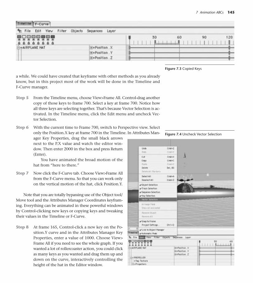
a while. We could have created that keyframe with other methods as you alreadyknow, but in this project most of the work will be done in the Timeline andF-Curve manager.
Step 5 From the Timeline menu, choose View>Frame All. Control-drag anothercopy of those keys to frame 700. Select a key at frame 700. Notice howall three keys are selecting together. That’s because Vector Selection is ac-tivated. In the Timeline menu, click the Edit menu and uncheck Vec-tor Selection.
Step 6 With the current time to Frame 700, switch to Perspective view. Selectonly the Position.X key at frame 700 in the Timeline. In Attributes Man-ager Key Properties, drag the small black arrowsnext to the P.X value and watch the editor win-dow. Then enter 2000 in the box and press Return(Enter).
You have animated the broad motion of thehat from “here to there.”
Step 7 Now click the F-Curve tab. Choose View>Frame Allfrom the F-Curve menu. So that you can work onlyon the vertical motion of the hat, click Position.Y.
Note that you are totally bypassing use of the Object tool/Move tool and the Attributes Manager Coordinates keyfram-ing. Everything can be animated in these powerful windowsby Control-clicking new keys or copying keys and tweakingtheir values in the Timeline or F-Curve.
Step 8 At frame 165, Control-click a new key on the Po-sition.Y curve and in the Attributes Manager KeyProperties, enter a value of 1000. Choose View>Frame All if you need to see the whole graph. If youwanted a lot of rollercoaster action, you could clickas many keys as you wanted and drag them up anddown on the curve, interactively controlling theheight of the hat in the Editor window.
7 Animation ABCs 145
Figure 7.3 Copied Keys
Figure 7.4 Uncheck Vector Selection

Step 9 Now we want to swing the hat in and out of the Z space. Click on Posi-tion.Z. At frame 240, create a key and drag it upward to 400 on the graph.At frame 330, add another key and drag the value to –400. Check the topview for a better sense of what’s going on with the animation path andplay the animation. (Click the Play button on the Animation Timelineor press F8.)
Working with Custom TangentsWhen you previewed the animation, you saw the hat dipping below the floor atthe beginning. (That occurred because the sudden rise of the hat at Frame 165affected the whole curve.) Click the Position.Y graph and you’ll see the dip onthe graph between frames 0 and 60. Also, the hat is traveling along the path atthe same monotonous speed.
Step 1 First let’s fix that dip. In the left panel of the F-Curve window, click onPosition.X, Position.Y and Position.Z so they are all red (selected). Draga rectangular selection rectangle over the keys (stacked on top of eachother) at Frame 0. Command-click (right-click) on the keys at frame 0.From the contextual menu, choose Hold. Now the original vertical po-sition is maintained until it changes at the next keyframe.
Step 2 Now we’ll customize tangents for more natural timing by creating someEase-ins on the keys at frame 700. Make sure Position.X, Position.Y, andPosition.Z are selected (red) and choose View>Frame All so you can seeall the graphs. Drag a selection rectangle over all the keys at frame 700.Command-click (right-click) any one of the keys, and choose Curves>Custom Tangents>Soft Interpolation to make tangent handles appear.Then (from the same contextual menu) choose Curves>Custom Tan-gents>Flat. Drag the tangent handles for each curve back to the frame500 mark on the graph.
Step 3 With Airplane Hat still selected, set the current time to frame 120. Inthe Attributes Manager Coordinates panel, click any of the letters R andset starting keyframes. Move the current time to 700 frames. Then clickon just the H in R.H, and keyframe a value of 360 degrees. The hat willspin in a full 360 degree rotation from frame 120 to frame 700.
146 CINEMA 4D
Figure 7.5 Hold Keyframes
◆ Tips: • If it is difficult to see the exact
time on the time ruler, feedbackfor the precise time and valueappears at the lower left of theTimeline.
• You can Control-click a key on a track in the general vicinityand then enter the exact value inthe Time box in Key Properties.
• Note that the blue current time tab in the Timeline orF-Curve manager gives morespecific control when workingin zoomed views than the Cur-rent time slider in the Anima-tion Timeline.
Figure 7.6 Ease Ins at Frame 700

Step 4 Working in the F-Curve window, select the words Rotation.P. ChooseView>Frame All.
Scrub through the timeline and when you feel the time is right,Control-click a few new “pitch” keys on the curves. Make sure the cur-rent time is on the selected key you are currently adjusting so you seethe effects correctly in the editor, and drag the small black handles tothe right of the Value box in Key Properties, or simply drag the key upor down on the graph. For now, make only a few gentle tilts to give theidea that the hat is blowing in the wind. (Once you get the basics down,you can copy this file and flip the hat all over the place.)
Step 5 Select Rotation.B and give the hat a few gentle bank tilts as well.
Step 6 At frame 700, Pitch and Bank values will need to be “zero’d out” (re-turned to 0 value) so the hat will sit flat on the floor.
On the DVD: See Chapter 07>EXAMPLES>Airplane Hat.c4d.
7 Animation ABCs 147
A classic principle of animation is that most motion doesnot happen and end suddenly, but eases into and out ofthe action. On a graph, a straight diagonal line betweentwo keys means that the change is beginning immedi-ately and happening at a constant rate.
Ease Ins: In Step 2 you created Ease Ins on the final X, Y, and Z Position keys. By flattening these curves, youcaused the values of the selected keys to be effectivesooner and longer. The effect is that the hat will slowdown and float to the floor.
A Typical Ease Out Example: By placing an Ease Out ona 0 value key at Frame 0 of a Position.Y track, the objectdoes not rise immediately but sits still a moment, thenstarts to rise slowly, and then picks up speed. (The flatpart of the curve keeps the motion at its starting valuelonger, as the more drastic part of the curve shows amore accelerated progression toward the new value.)
Easy Ease: Choosing Easy Ease from the contextual menuplaces an Ease In on the incoming tangent and an EaseOut on the outgoing tangent of a selected key.
◆ Tips: • When fine-tuning animation,
work in Wireframe or Isoparmview in the Editor.
• Rendering as Editor (on the firstpage of the Render Settings) willtell you what you need to knowabout the movement withoutlong render times.
Figure 7.7 An Ease Out of the First Key
Take It Easy: Ease Outs, Ease Ins, and Easy Ease

Animating the PropellerStep 1 In the Objects Manager, open the Hierarchy and select the Propeller on
Stem object. In the Attributes Manager Coordinates panel, keyframe aR.H value of 0 at frame 0.
Step 2 Drag the name Propeller on Stem and drop it into left window of theF-Curve manager. Choose View>Frame All. Control-drag a copy of theframe 0 key to frame 700, and give the new key a value of 5000.
Step 3 Between frames 0 and 120, we want the propeller to sputter tentatively.At frame 20, keyframe a value of 600, and at frame 25 set a keyframe of0. (Again, the easiest way to do this is to Control-click a new point onthe track and drag it to the correct time while watching the feedbackline. Then, enter the Rotation value in the Key Properties value box.)
Step 4 Choose View>Frame all. Drag a rectangular selection over all three keys.Control-click on any one of the selected keys and drag two copies ofthem to the right on the track. Center the first copy of three keys onframe 50 and the second copy at frame 90. The very last key of the keysthat you just copied (a 0 value key) should be around frame 100.
Step 5 Now go back and experiment with raising the values of the keys at frame50 and 85, and adjust the spacing between the keys to get the effect youwant. The propeller can gradually gain strength or begin in a suddenspurt as it tries to start up. Try setting Frame 50 at 1500 and frame 90 at5000. This value you are currently working with is how many degrees thepropeller is spinning.
By now you have noticed that the curves are dipping down below 0 betweensome of the keys. Actually that could be a good thing in this case. It’s creating a “re-coil” effect and displaying one of the classic animation principles. (See “Some Ani-mation Principles at Work.”) This tiny bit of action communicates the idea that thehat is alive and trying oh so hard to get up steam so it can take off. If you did notwant that dip, just place a Hold on the third key of each set.
Step 6 Use the Move and Scale tools at the top right of the F-Curve window (youhave to drag on the tool icons) to position the graph so you can seeframes 90 though 700. Shift-click to select the keys at frame 100 and 700and choose Curves>Custom Tangents>Soft Interpolation, and thenCurves>Custom Tangents>Flat. (Those can be chosen from the TimelineMenu Curves menu, or by Command-clicking (right-clicking) on one ofthe selected points to access the contextual menu.)
Step 7 You can use the tangent handles of the keys at frames 100 and 700 tocontrol the slope of the curve and fine tune the rotation of the hat asit takes off and lands.
On the DVD: For more about Animation Principles, See Chapter 07>EXTRA!EXTRA!>References.
148 CINEMA 4D
◆ Tips: • A picture is worth a thousand
words! To clearly understandthis complex motion, study theF-Curves of the Example C4Dfile. (Chapter 07>EXAMPLES>Airplane Hat.) As you work tofine tune each element, checkout the corresponding graph inthe finished animation.
• Less is more. It’s tempting toadd lots of keys, isn’t it? Youanimation will be more ele-gant if you use fewer keys anduse the tangent handles to ad-just the curves for smooth mo-tion. Look at the example C4Dfile to see how few keys are onthe F-Curves.
• Control-click on the Timelineruler to create markers for im-portant points in the animation.Double-click the marker to enteridentifying text.
• To temporarily turn off VectorSelection (so you can select in-dividual keys), hold down theOpt (Alt) key.
7 Animation ABCs 149
Some Animation Principles at Work
• Anticipation. Preliminary action that sets the stagefor the major action. The bouncing of the airplanehat creates a build-up before take-off.
• Exaggeration. The overdone vertical scaling of theAirplane Hat as it stretches upward after a bounce isan exaggerated motion that adds drama and helpsthe viewer grasp what’s going on.
• Self-Driven Characters. The short sputters of theAirplane Hat propeller create the illusion that the hat
itself is struggling to fly, and not being manipulatedby some outside force.
• Arcs. The hat moves on an elegant path of arcs,rather than straight lines here to there.
• Asymmetry. Jumbled keys (Batty Box) and the VibrateExpression (Crown of Stars) are typical randomizationsthat prevent motion from looking too planned andmechanical.
Anticipatory Hops
Step 1 In the F-Curve window you should still see the Rotation.H curve forthe Propeller on Stem.
Drag the object Airplane Hat to the F-Curve window also. Click on onlyRotation.H ( for Propeller on Stem) and Position.Y (for Airplane Hat).Drag a rectangular selection over the keys from frame 0 through 130and choose View>Frame Selection.
Step 2 Working on the Position.Y track, Control-click new keys and positionthem to lift the hat in response to the propeller. (When the propellerstops, return the hat to its original vertical position. These little hopswill add to the anticipation and build up toward the actual liftoff ofthe hat.
Step 3 Command-click on these points and choose Tangents>Soft Interpola-tion. You can then hold down the Shift key and adjust the tangent han-dles independently. By dragging the tangent handles slightly upward,you can influence the curve to rise in the areas where the hat should liftinto the air.
In other words, you don’t have to place keys at the high points of the hopsbut can use the tangent handles to raise the curve. Fewer keys and more workwith curves will make for smoother motion and a much less cluttered graph! It’sthe position of the curve at any point in time determines “how high” the hat ispositioned. These little hops will add to the anticipation and buildup toward theactual lift off of the hat. Now that you’ve been introduced to the power of work-ing with Tangent handles, you could go back and delete the keys on the Rota-tion.H curve at Frames 20, 50, and 90 (which are currently defining the highestdegrees of rotation) and use tangent handles to shape those curves.
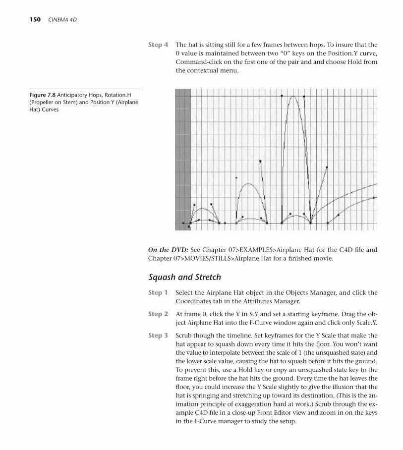
Step 4 The hat is sitting still for a few frames between hops. To insure that the0 value is maintained between two “0” keys on the Position.Y curve,Command-click on the first one of the pair and and choose Hold fromthe contextual menu.
150 CINEMA 4D
On the DVD: See Chapter 07>EXAMPLES>Airplane Hat for the C4D file andChapter 07>MOVIES/STILLS>Airplane Hat for a finished movie.
Squash and Stretch
Step 1 Select the Airplane Hat object in the Objects Manager, and click theCoordinates tab in the Attributes Manager.
Step 2 At frame 0, click the Y in S.Y and set a starting keyframe. Drag the ob-ject Airplane Hat into the F-Curve window again and click only Scale.Y.
Step 3 Scrub though the timeline. Set keyframes for the Y Scale that make thehat appear to squash down every time it hits the floor. You won’t wantthe value to interpolate between the scale of 1 (the unsquashed state) andthe lower scale value, causing the hat to squash before it hits the ground.To prevent this, use a Hold key or copy an unsquashed state key to theframe right before the hat hits the ground. Every time the hat leaves thefloor, you could increase the Y Scale slightly to give the illusion that thehat is springing and stretching up toward its destination. (This is the an-imation principle of exaggeration hard at work.) Scrub through the ex-ample C4D file in a close-up Front Editor view and zoom in on the keysin the F-Curve manager to study the setup.
Figure 7.8 Anticipatory Hops, Rotation.H(Propeller on Stem) and Position Y (AirplaneHat) Curves

Step 4 For even more realism, go back and keyframe the X and Z scale valuesto work along with the Y squashes you just keyframed. In order to main-tain its volume, an object squashed on the Y axis would stretch (increasein scale) slightly on the X and Z at the same time.
7 Animation ABCs 151
Figure 7.9 Squash and Stretch
Adjusting The Working Views
When working on fine-tuning like thehops and squashes above, it is criticalthat you adjust your views so you cansee what you’re doing. For example, usea close-up Front view so you can clearlysee the relationship of the object to thefloor. For a close view of keys in theTimeline and F-Curve windows, you can use the Move and Scale icons onthe top right of the windows, or betteryet, make the habit of using the 1 and 2 keys (just like you use them in the Editor window to move and scale).
In the View menu for the Timelineand F-Curves, choose Frame All whenyou need to see the overall picture. Inthe fine-tuning stage, however, that viewis nothing but mass confusion. Drag aselection rectangle only over the keys inthe area you are working on. The fewerkeys, the better. Choose View>FrameSelection. Then, click on only the tracksnecessary for comparing events in timeand you’ll have a clear picture of thekeys and tangents. If you need to moveon to the next section, use the 1 key toslide over as you work.
Figure 7.10 Mass Confusion
Figure 7.11 View>Frame Selection
Figure 7.12 In Close
Make further adjustments to the animation as you work toward smooth andbelievable motion. Command-click (right-click) on keys and choose commandslike Hold and Custom Tangents>Soft Interpolation from the contextual menu tomake the object behave like you want it to. Add some flips, as if the hat were sud-denly hit by a gust of wind, by adding Rotation keys. Study the example movieto see the tangent handles and other adustments. Save several copies of this fileso you can practice all kinds of maneuvers.
● Springboard! In Chapter Five, you learned how to copy animation whenyou copied the tracks of Materials in the Timeline. In that case, you copiedtracks with keys to objects that had no previous animation. In this case,when you copy the Airplane Hat in the Objects Manager, all its animationcomes along with it and everything happens identically for the two objects.(If you played the animation you would only see one hat, because theywould occupying the same space.) However, by tweaking keys, you canquickly send the copy on an individual path and its propeller spinning tothe beat of a different drum. Try it. Copy Airplane Hat, drag the name ofthe copy into the F-Curve window and start tweaking keys.
B Is for Batty Box: Combining Time Curves and PLA
This project will show you how to use Time Curves to make fidgety motions thatare natural and random and how to add interacting Point Level Animation fora more organic feeling.
Step 1 Choose File>Open and navigate to Chapter 07>C4D Files>Batty Box>Batty Box.c4d. Choose File>Save As and save the file as Batty Box in yourModels folder.
Step 2 Open the hierarchy and select the Bat Wing object (inside BAT WINGS).The wings are in a good starting position, so in the Attributes ManagerCoordinates panel, Control-click (right-click) the H in R.H and set astarting key for the current rotation at frame 0.
Step 3 At frame 90, enter –45ºs in the Rotation.H box and set a keyframe.
Step 4 Choose the Animation Layout. Drag the object Bat Wing into the Time-line window. Look at the Timeline and you see that there are only twokeys, one for an “open” state of the wings and one for when the wingsare drawn back. How’s that for boring animation?
Step 5 In the Timeline, select the word Bat Wing. From the Timeline menu,choose File>New Track>Time.
152 CINEMA 4D
Figure 7.13 Bat Wing Hierarchy

Step 6 Click on the Bat Wing Rotation.H track. Notice that the Sequence Prop-erties for that track sequence appear in the Attributes Manager and thatthere is an empty box labeled Time Track.
Step 7 Now you will apply the Time Track to a specific sequence, the Rotation.Hof the Bat Wing. In one motion, click and drag the word Time next to theTime Track across the Timeline Window and drop it into the Time Trackbox in the Attributes Manager. (In other words, don’t click the word Timefirst, and then try to drag it.)
The Time Track you just created is a graph that shows what percentage of theanimation is completed at a given point in time. The first gray line above the linelabeled 0 represents 100 percent. Study the graph and you’ll see that at frame 0the animation is 0 percent complete and at frame 90, the end, it is 100 percentcomplete. That’s pretty much a no brainer. This turns out to be much cooler thanit appears on first glance. By Control-clicking (right-clicking) keys along the time-line you can cause the Rotation.H state of the wings to be at any position betweenthe two states you set. And the ability to copy keys allows you to set up many upand down, and somewhere in between positions very rapidly. This comes in reallyhandy any time you need fidgety, randomly flappity motion.
Step 8 Starting at Frame 5 on the ruler, Control-click seven keys. Drag themup and down to slightly random positions, alternating the high andlow values. See Figure 7.14.
7 Animation ABCs 153
Figure 7.14 First Bat Wing Keys
Step 9 Drag a rectangular selection tool over the existing keys, and Control-drag (right-click) a copy. Continue to copy keys across until you havekeys every 3–5 frames. Want to make some of the flaps faster? Just se-lect a section of frames and drag the red handles on the top of the rulercloser together.
Step 10 Now do a little hand work. Move some of the keys, further random-izing the values between 0 and 100 percent, and also make the hori-zontal spacing between the keys more uneven. See Figure 7.15.
If you render a movie at this point, you’ll see some fine flapping. However,the wings themselves are stiff and don’t seem to be responding to the motion or
Figure 7.15 All Bat Wing Keys
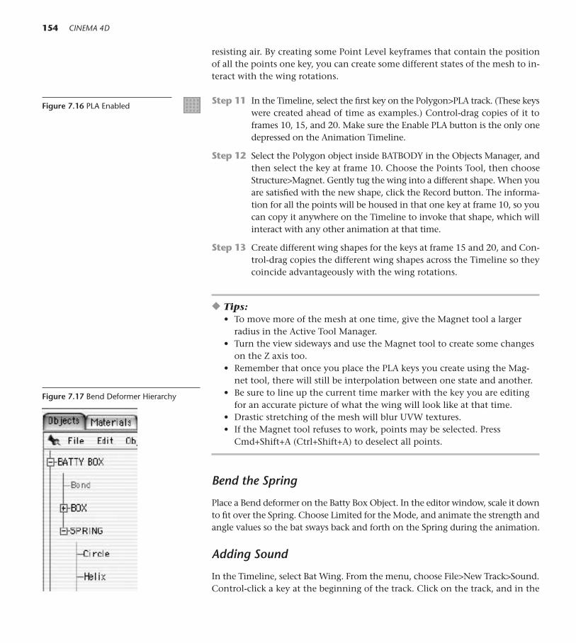
resisting air. By creating some Point Level keyframes that contain the positionof all the points one key, you can create some different states of the mesh to in-teract with the wing rotations.
Step 11 In the Timeline, select the first key on the Polygon>PLA track. (These keyswere created ahead of time as examples.) Control-drag copies of it toframes 10, 15, and 20. Make sure the Enable PLA button is the only onedepressed on the Animation Timeline.
Step 12 Select the Polygon object inside BATBODY in the Objects Manager, andthen select the key at frame 10. Choose the Points Tool, then chooseStructure>Magnet. Gently tug the wing into a different shape. When youare satisfied with the new shape, click the Record button. The informa-tion for all the points will be housed in that one key at frame 10, so youcan copy it anywhere on the Timeline to invoke that shape, which willinteract with any other animation at that time.
Step 13 Create different wing shapes for the keys at frame 15 and 20, and Con-trol-drag copies the different wing shapes across the Timeline so theycoincide advantageously with the wing rotations.
◆ Tips: • To move more of the mesh at one time, give the Magnet tool a larger
radius in the Active Tool Manager.• Turn the view sideways and use the Magnet tool to create some changes
on the Z axis too. • Remember that once you place the PLA keys you create using the Mag-
net tool, there will still be interpolation between one state and another. • Be sure to line up the current time marker with the key you are editing
for an accurate picture of what the wing will look like at that time.• Drastic stretching of the mesh will blur UVW textures.• If the Magnet tool refuses to work, points may be selected. Press
Cmd+Shift+A (Ctrl+Shift+A) to deselect all points.
Bend the Spring
Place a Bend deformer on the Batty Box Object. In the editor window, scale it downto fit over the Spring. Choose Limited for the Mode, and animate the strength andangle values so the bat sways back and forth on the Spring during the animation.
Adding Sound
In the Timeline, select Bat Wing. From the menu, choose File>New Track>Sound.Control-click a key at the beginning of the track. Click on the track, and in the
154 CINEMA 4D
Figure 7.16 PLA Enabled
Figure 7.17 Bend Deformer Hierarchy

Attributes Manager Sound Properties panel click the small (unlabeled) button tothe right of the empty Sound box. Navigate to LIBRARIES>MUSIC AND SOUNDEFFECTS>Squeaking.wav on the DVD.
CINEMA does not render the sound out with the movie, but since most peo-ple prefer to put sequences of animation together with sound in a compositing ap-plication that’s not generally problematic. If you don’t have a compositing programyou can use the inexpensive QuickTime Pro or free iMovie to add final sound.
The sound previews on insertion, but to play it every time with the anima-tion you have to turn on the Play Sound During Animation button in the Ani-mation Timeline.
● Springboard! The wings could be animated with PLA (and maybe thehelp of some deformers) to crumple up as the Bat disappeared down intothe box. Patience is required, but the bat popping in and out of the box tothe turn of the crank and a spooky tune would be so worth it.
7 Animation ABCs 155
Figure 7.18 Bend Deformer
Figure 7.19 Play Sound

C Is for Crown
A crown of flying stars is the classic sign of a knocked-out cartoon character. Makeyour own 3D version in this project.
Step 1 Choose File>Open and navigate to Chapter 07>C4D Files>Crown ofStars.c4d. Choose File>Save As and save the file as Crown of Stars inyour Models folder.
Step 2 Command-click (right-click) on the Glowing Star object and chooseNew Expression>Align to Spline.
Click the Align to Spline tag and in the Attributes Manager, clickthe Tag panel. Drag the word Circle from the Objects manager into thebox for Spline Path.
Step 3 Set the current time to 0, and keyframe a 0 percent Position value inthe Attributes Manager Tag Properties. At 90 frames, enter a value of100 percent and set a keyframe.
Step 4 Command-click (right-click) on the Glowing Star object, and drag toNew Expression>Vibrate Expression. Check the check boxes for EnableScale and Enable Rotation, giving Rotation an H Amplitude (only thefirst box) of 180º. Enter a value of 10 percent for Seed.
Step 5 Select Glowing Star and Circle. Press the G key to group them and re-name the Null Object as Glowing Star 1.
Step 6 Make three copies of Glowing Star 1 and rename the copies as Glow-ing Star 2, Glowing Star 3, and Glowing Star 4.
Step 7 Open Glowing Star 2, and select the Circle inside. From the top menu,choose Structure>Edit Spline>Move Down Sequence.
Step 8 Repeat Step 7 with Glowing Star 3 but choose Move Down Sequencetwo times, and with Glowing Star 4 choose Move Down Sequence threetimes.
By changing the position of the first point on each Circle with MoveDown Sequence, the trip along the Circles will start at a different pointfor each Glowing Star.
Step 9 Select Glowing Stars 1 though 4 and press G to group them, namingthe group Star Track 1. Make two copies of Star Track 1, naming thecopies Star Track 2 and Star Track 3.
Step 10 Switch to the top view. Use the Object Axis tool and the Move tool tocenter the axes of Star Track 1, Star Track 2, and Star Track 3. Choosethe Model tool and the Rotate tool and use the green Rotate handle torotate Star Track 2 and Star Track 3 as pictured in Figure 7.20. Give StarTrack 2 a 25º Pitch rotation, and Star Track 3 a –25º Pitch rotation.
156 CINEMA 4D
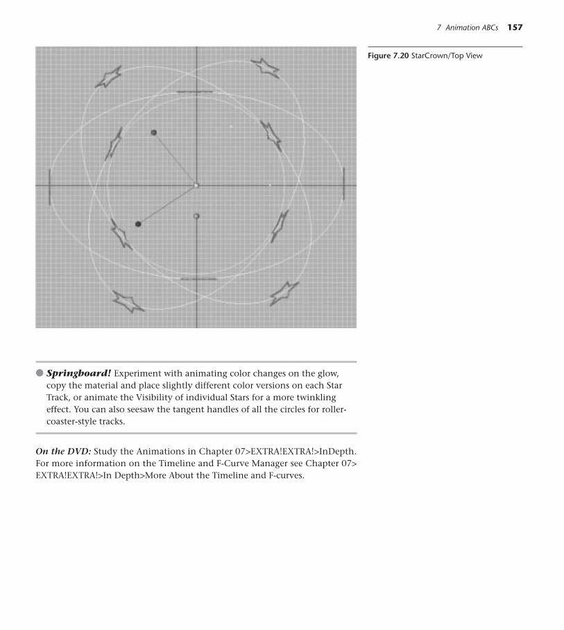
● Springboard! Experiment with animating color changes on the glow,copy the material and place slightly different color versions on each StarTrack, or animate the Visibility of individual Stars for a more twinklingeffect. You can also seesaw the tangent handles of all the circles for roller-coaster-style tracks.
On the DVD: Study the Animations in Chapter 07>EXTRA!EXTRA!>InDepth.For more information on the Timeline and F-Curve Manager see Chapter 07>EXTRA!EXTRA!>In Depth>More About the Timeline and F-curves.
7 Animation ABCs 157
Figure 7.20 StarCrown/Top View

This Page Intentionally Left Blank

8Head Shots
159
Figure 6.1
T here are infinite methods for building heads, human and otherwise. This tu-torial employs one simple method for building a head with generic features.
On the DVD: See Chapter 08>EXTRA!EXTRA! for more head-building methods,example files, instructional movies, and pointers to other tutorials for buildingheads and facial features of various complexity levels.
The Symmetry Method
In this tried and true head-building process, only one side of the head is sculptedinside a Symmetry object and later rejoined into a single mesh.
The Basic Head Shape
Step 1 In a new .c4d file (File>New), start with a Cube primitive and work inWireframe display. Enter 150 for Size.X, 175 for Size.Y, and 160 for Size.Zin Object Properties. Press the C key to make it editable. Save the file asSymmetry Head in your Models folder (File>Save As).
Step 2 From the top menu, choose Structure>Subdivide. Enter 2 in the Sub-division input box and check the check box for HyperNURBS Subdi-vide. Choose the Front view and choose Edit>Frame Active Object sothe head fills the window.

160 CINEMA 4D
Step 3 Choose the Points tool, and press the letter K to access the Knife tool.You’ll be using the Knife tool to add three new polygonal divisions inthe first row of polys above the X axis. Click outside the form on theleft and Shift-drag three lines all the way across the form. Release themouse outside the form on the right each time you drag a line. Referto Figure 8.3.
Step 4 Add three cuts in the row of polys below the X axis, and three more inthe next row down, being careful not to intersect these last lines withthe curved edges of polys above and below them. Then drag the Knifetool twice vertically in the first row of polys to the right of the Y axis,as shown in Figure 8.3.
Step 5 Choose the Rectangle selection tool, and in the Active tool uncheck OnlySelect Visible Objects. Drag a selection over the left half of the head, upto but not including the vertical midline, and press the Delete key to re-move the points and polys. Don’t forget to save every few steps (File>Saveor Cmd+S/Ctrl+S).
Step 6 Still using the Rectangular selection tool, select all the points on the openleft edge of the head. From the top menu, choose Selection>Set Selection.In the Attributes Manager, click the Basic panel and type EDGE in theXname box. Click in the Objects Manager to deselect the Selection tag.
As you begin to model, these points may stray off of their current 0 positionon the X axis. This selection may be quickly accessed to send the points to backto the center.
Step 7 Choose a Symmetry object, and place the Cube into it. Then create aHyperNURBS object and place the Symmetry object as its child. At anypoint in the modeling process, you can turn either of these off tem-porarily by clicking their green check mark so it turns to a red cross mark.
Creating a Nose
Step 1 Make sure the Cube is selected and switch to the Polygons tool and theMove tool. Shift-click to select the polygons, two across and three down,immediately under the X axis and on the left edge.
Step 2 Press the D key to access the Extrude tool. In the Active tool tab, enter10 for offset and press Return (Enter). Then enter 5, and press Return(Enter) again.
Step 3 Switch to the Perspective view and use the 3 key to turn the view as inFigure 8.5. With the end polys still selected, scale them down on theX and Y axes. Select and Delete the new polys (on the inside edge of thehalf head) that were created when the nose was extruded. If you need
Figure 8.2 Rectangle Selection Tool
Figure 8.3 Head, Subdivided with the KnifeTool and Halved
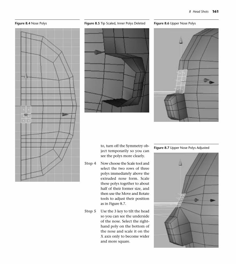
8 Head Shots 161
to, turn off the Symmetry ob-ject temporarily so you cansee the polys more clearly.
Step 4 Now choose the Scale tool andselect the two rows of threepolys immediately above theextruded nose form. Scalethese polys together to abouthalf of their former size, andthen use the Move and Rotatetools to adjust their positionas in Figure 8.7.
Step 5 Use the 3 key to tilt the headso you can see the undersideof the nose. Select the right-hand poly on the bottom ofthe nose and scale it on theX axis only to become widerand more square.
Figure 8.4 Nose Polys Figure 8.5 Tip Scaled, Inner Polys Deleted Figure 8.6 Upper Nose Polys
Figure 8.7 Upper Nose Polys Adjusted
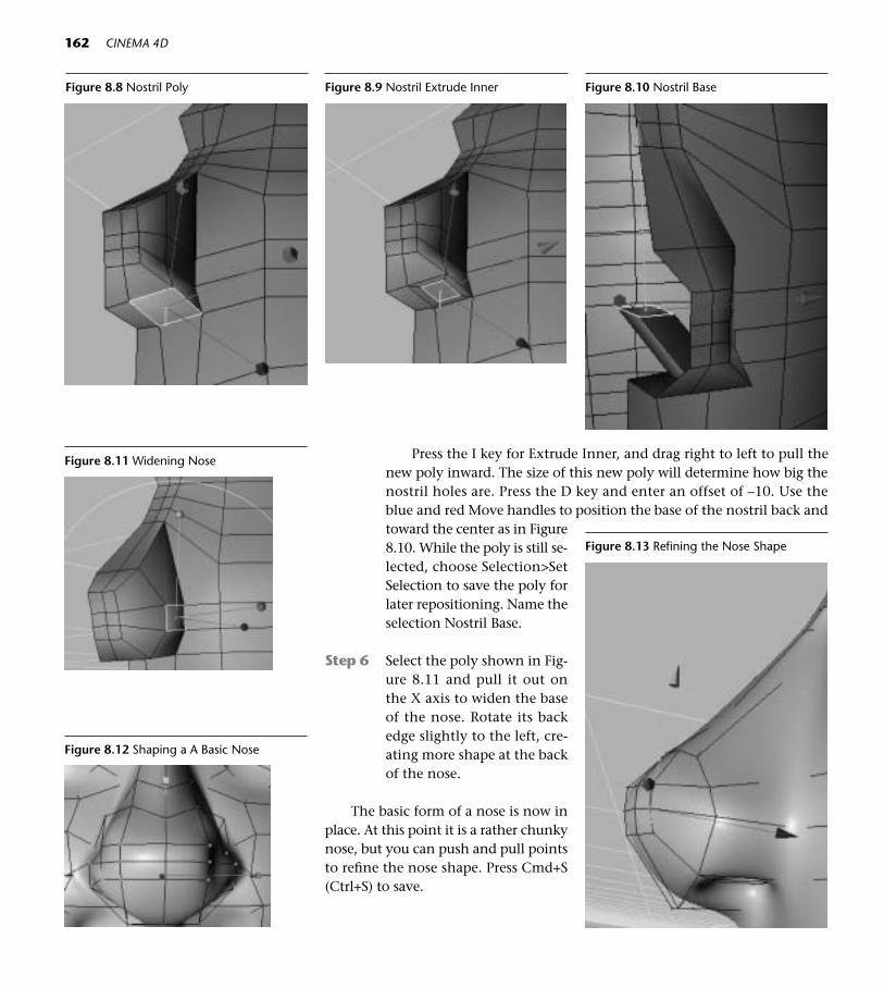
Figure 8.10 Nostril Base
Figure 8.11 Widening Nose
Figure 8.12 Shaping a A Basic Nose
162 CINEMA 4D
Press the I key for Extrude Inner, and drag right to left to pull thenew poly inward. The size of this new poly will determine how big thenostril holes are. Press the D key and enter an offset of –10. Use theblue and red Move handles to position the base of the nostril back andtoward the center as in Figure8.10. While the poly is still se-lected, choose Selection>SetSelection to save the poly forlater repositioning. Name theselection Nostril Base.
Step 6 Select the poly shown in Fig-ure 8.11 and pull it out onthe X axis to widen the baseof the nose. Rotate its backedge slightly to the left, cre-ating more shape at the backof the nose.
The basic form of a nose is now inplace. At this point it is a rather chunkynose, but you can push and pull pointsto refine the nose shape. Press Cmd+S(Ctrl+S) to save.
Figure 8.8 Nostril Poly Figure 8.9 Nostril Extrude Inner
Figure 8.13 Refining the Nose Shape

8 Head Shots 163
The Eye Shape
The secret to nicely contoured eyes is to prepare a good beginning shape. De-pending on the style of eye you want to end up with, you can start with circlesor rectangles or the octagonlike shape used here. Move some points into a goodstarting position like those shown in Figures 8.14 and 8.15.
Step 1 Choose the Polygon tool and select the four polys of the basic eye shapeshown in Figures 8.14 and 8.15.
Step 2 Press I for Extrude Inner and drag the mouse from right to left three orfour times (depending on how much detail and polygon count you havein mind) to create skinny polys aound the eye shape.
Before you start moving the eye points around too much, you may want totake time to make some set selections of points to use later when you animateexpressions.
Step 3 Push and pull points to create the eye shape you want. If you chooseto use sphere primitives for eyeballs, insert a sphere now so you canpush the surface of the eye to wrap around it correctly.
Step 4 If you want a raised rim around the eye opening, adjust the points ofthe polys created with the last Extrude Inner to be even slimmer andperform a slight Extrude to raise the rim.
Step 5 Reposition some points around the inner corner of the eye to make atiny square polygon. Inner Extrude and Extrude this polygon to createa tear duct, and then move all the corner points further toward the Yaxis so the corner is offset from the eyeball. Select the four innermostpolys in the eye area and move them back on the Z axis to create aneye cavity. You don’t need all those polys on the inside, so you can de-lete any that won’t be seen.
◆ Tips: Take care that you don’t Ex-trude Inner so far that any of thepoints cross over each other.
Figure 8.14 Starting Eye Shape Isolated
Figure 8.15 Starting Eye Shape
Figure 8.16 Eye Rim Points

164 CINEMA 4D
Step 6 Either apply the eyeball ma-terial in GOODIES>MATERI-ALS>CharacterMaterials> toa sphere, or use the Eyeballmodel in Chapter 08>EXAM-PLES. (For cartoon-style heads,you could also move the fourcenter eye polys back slightlyand pull the center point for-ward to create an eye surfacethat remains part of themesh.)
Figure 8.17 Rim Scaled/Extruded Figure 8.18 Inner Eye Corner
Those Elusive Points
When you modeling your first heads, it seems like pointsare forever dipping beneath the surface, tangling aroundeach other and careening off into space. You can save alot of frustration by setting up views so you can see ex-actly what you’re doing. Set your display to Isoparm, andthen go to Window>New View Panel and set its display to Gouraud. Use the 2 key and drag the mouse to placeyourself close to the surface. You can work in either view,and when you can’t see points beneath the surface, justclick on a neighboring point you can see and then checkthe Isoparm view to trace the connecting line back to thehidden point.
When facing a point, edge, or poly, using the Cmdkey and the Move tool to drag the element away from ortoward the screen can be an intuitive way to work. Drag-ging the mouse with the righthand button depresseddoes the same thing and is much more natural, so a twoor three-button mouse is a must-have accessory for Macusers who plan to spend a lot of time modeling. However,it can be tricky to judge the amount of movement whenpushing points toward and away from you. Nudging thegreen, red, and blue Move handles of the point is oftenmore accurate and you can easily comprehend a point’sdirection from almost any angle. By using the 3 key tokeep the view tumbling, you can quickly tweak surfacepoints and keep a critical eye how the point pushes areaffecting the mesh.
Figure 8.19 Two Windows

8 Head Shots 165
Making An Ear
We’ll make a simple ear for now.
Step 1 Before starting the ear, face the side profile of the head and select thePoints tool. Use the Magnet tool to shape the back of the head (Radius150) and the jaw (Radius 60).
Step 2 Move points to create a starting shape shown in Figure 8.22.
Step 3 Select the base ear polys, and press the I key to Extrude Inner once ortwice. (The more detail you want, the more extrusions you need to addat every stage of making the ear form.) Type D to extrude. In the ActiveTool tab, enter an offset value of 5 and click Apply. Choose the Scale tool
Once the basic polygonal structure of facial features areset up, it can still be a long, long way to an elegantlyhand-modeled head. The patient pushing and pulling ofpoints, edges, and polys is the way to get there, and thejourney can take some time. The good news is that everyhead you make will be born faster and better looking.And once you have made some decent ones, they can becopied and tweaked into a thousand other personalities.Review your welding skills from Chapter 2 as they willcome in handy now. For example, select the mouth polys,
disconnect some copies, and create different mouths toweld in later. The head in Figure 8.20 was copied, and themouth polys were replaced to create the different versionin Figure 8.21. By using the Edit Structure>Disconnectand Split and saving extra copies, whole libraries of differ-ent features can be created for a basic head and weldedback in later.
What’s in the Road . . . Ahead? The Bad News and The Good News
Figure 8.20 Alien
Figure 8.21 Alien Princess
Figure 8.22 Adjusted Head and Ear Shape

166 CINEMA 4D
and drag the mouse from left to right, so that the ear flares out. Don’tworry about the size of the ear for now, you can adjust it later. Press theI key for Extrude Inner, enter an offset value of 3, and click Apply twotimes.
Step 4 Choose the points shown in Figure 8.25, and pull them up, more to-ward the back of the head and back into the head. Select the polygonshown in Figure 8.26, and rotate its right hand edge back slightly. Pressthe D key to extrude the poly back into the head.
Figure 8.23 Ear Polys Extruded Inner
Figure 8.24 Ear Flared
Figure 8.25 Points for Ear Canal Figure 8.26 Poly for Ear Canal Figure 8.27 Ear Canal Formed

8 Head Shots 167
Step 5 Select a polygon like the one in Figure 8.28, and Extrude Inner to cre-ate some more points for detail of the bony structures inside the ear-lobe. Proceed to push and pull points and polys, shaping the ear. Studysome reference photos, real ears, and the example files for help with theunusual and endlessly individual surfaces of the inner ear lobe. Whenyou are finished, select all the polygons within that original ear shapeyou began with and choose Structure>Edit Surface>Disconnect. Save acopy of the file for your Library (File>Save As). Also, save a Selection ofall the Ear points for size adjustment later.
Shaping The Head
While still working on a symmetry object, you can go ahead and shape up thehead a bit.
Step 1 Use the Magnet tool to round up the top of the head and sculpt thejaw. Be careful to use the correct magnet radius to keep from pullingalready finished contours out of place.
Step 2 Pay some attention to the contours of the face from the profile view.You can select polygons in the cheek to pull them forward.
Step 3 For more forehead shape, face the side of the head and make an addi-tional knife cut above the eyes. Then pull the front polys out for a morepronounced forehead.
Step 4 Now work with points to soften any ridges that may have popped up.Try to adjust the points so that the edges follow the muscle contoursof the face as naturally as possible.
Figure 8.28 Poly for Ear Detail Figure 8.29 Ear
Figure 8.30 Cheek Poly Pulled Out
◆ Tip: Isolate Select the polys of asingle feature, and choose Select>Hide Unselected to clear away all those other things you are notcurrently working on. ChooseSelection>Unhide All to bringeverything back.

168 CINEMA 4D
Step 5 You can always extrude inneranywhere you want more de-tail. In Figure 8.33, an eye-brow shape and a more detailaround the mouth area wereadded. After an Extrude In-ner, the extruded polygonsare often scaled on one axis(in this case only the Y) ormoved to create the neededcontours.
At this point, don’t worry aboutthe edge of the half head or refine-ment of the nose shape, the mouth, orthe chin. Those will be easier to workwith after the Symmetry object is con-verted to one mesh. Let’s do that now.
Figure 8.31 Added Knife Cut
Figure 8.32 Forehead Polys
Figure 8.33 Half Head Finished

8 Head Shots 169
Step 6 Double-click on the Selection Tag titled EDGE to activate the pointsaround the inner opening of the half head. Temporarily turn off the Sym-metry object by clicking the green check mark in the column to its rightin the Objects Manager. You can delete those stray points that are nolonger being used. Because the modeling process has created new pointson the edge, the selection is now incomplete. Hold down the Shift keyand click to select the new points (around the nose and where you knifedthe forehead), adding them to the selection. Be sure to choose Set Selec-tion again to incorporate the new points in that selection tag. ChooseStructure>Edit Surface>Set Value, change X to Set, and enter a value of 0.
Turn the Symmetry Object back on, and check the seam where thetwo halves join. You may need to adjust the position of the Cube ob-ject to realign the Cube object exactly on the Y axis. (Select the Cubewith the Model tool and make sure the value is 0 on the X axis.) If theseam is standing up in a ridge, just select the offending points and usethe blue Z handle to nudge them back on the Z azis until the seam dis-appears. It is sometimes helpful to increase the Tolerance of the Sym-metry object slightly.
Step 7 When the seam looks smooth, choose the Symmetry object and chooseFunctions>Current State to Object. Delete the Symmetry object (the onewith the Symmetry icon to its right) from the Objects Manager.
Now the two halves of the head are joined into one mesh, so you can dragthe Cube directly into the HyperNURBS object and delete the Symmetry object.No more splitting seam worries. But, remember that you are no longer editingboth sides simultaneously. It’s fairly easy to Shift-click to select points or polysas you continue to edit the surface though, and in some cases you actually wantasymmetry. For example, the easiest way to refine the nose shape is to Shift-clickto select opposing points on the nose and scale them closer together (or fartherapart) and move them on the Y and Z axes.
Making the Mouth and Chin
Before you start on the mouth, save yourself some grief by doing a little prelim-inary homework. By repositioning some points into some nice regular geometriesthat are fairly level on the Z axis, you’ll have an easier time when you form themouth and chin. Double-click on a point in the middle of the mouth area to de-termine its Z value, and then select all the points that define a general mouth areaand choose Structure>Edit Surface>Set Value to set all those points to the same Zlevel. (In this case, we are using four polys across and three down, but it can varydepending on the style of mouth and the required detail.) Then use the Moveand Rotate tools to establish a good starting plane for the mouth polys. This sim-ple step will prevent some ugly things happening when you extrude the mouth.
◆ Tip: Save some extra copies ofyour head at this point (File>SaveAs). You may want to go back andmake different mouths for thisbasic head.
Figure 8.34 Chin Polys
Figure 8.35 Mouth Polys

170 CINEMA 4D
Step 1 Select the Chin polys and use the Move and Rotate tools to set the basicposition. For now, just concentrate on the overall form. Later you canpush points to round the chin off and add detail.
Step 2 Now select the 12 beginning mouth polys shown in Figure 8.35. Ex-trude Inner two times as in Figure 8.36, and then scale the innermostpolys only on the Y axis as in Figure 8.37.
Step 3 Select the mouth area shown in Figure 8.38, and choose Selection>HideUnselected. Save some selections now for animation later. All MouthPoints, Top Lip, Bottom Lip, and Mouth Corners will all come in handylater. Also, make a selection of the two points immediately under thecenter of the nose. You’ll push them back later to create that little dipabove the upper lip. An Edge selection of the mouth opening will fa-cilitate closing the mouth completely.
Step 4 Select the inner mouth polygons and press D, dragging the mouseright to left to extrude a mouth cavity. With the polys still selected,scale them to make the base of the mouth larger. Extrude Inner to cre-ate the base of a tongue, and extrude the tongue back toward the frontof the face. You can add more detail to the tongue later if you want to.
Figure 8.36 Mouth Extrude Inner
Figure 8.37 Inner Polys Scaled on the Y Axis
Figure 8.38 Mouth Area Isolated
Figure 8.39 Tongue

8 Head Shots 171
Step 5 Begin forming the mouth by establishing the planes of the lips. Pull theselection in Figure 8.40 out on the Z axis, the rotate the top lip over soit faces downward more. Select the middle polys of the bottom lip as inFigure 8.41, and scale them on the Y axis to make the bottom lip fuller.Then move the polys down slightly and rotate them so the lip faces moreupward.
Step 6 Choose the Points tool, and start to push points to form the mouth. Pushthe corners away from you, and style the shape of the mouth to your lik-ing. By choosing opposing pairs of points, scaling them to move themcloser or farther apart, and moving them back in the Z axis, you canquickly create a very organic mouth. Make this mouth very generic andexpressionless. You can create more expressions later with the selectionsets you saved.
The mouth in Figure 8.44 is pro-portionally small. By clicking on theWHOLE MOUTH Selection Tag, youcan scale the mouth points to changethe mouth’s size.
Forming a Neck
Step 1 In the same way youprepared polygons for the mouth and chin (Figure8.34), organize a set of polys on the bottom of the head.
Step 2 Extrude the polys down from thehead, and adjust the points to smooththe neck form. Make a knife cut halfwaydown the neck and scale the new pointsdown slightly to give the neck more shape.
Figure 8.40 Mouth Polys Moved Forward Figure 8.41 Mouth Polys Rotated Figure 8.42 Pushing Mouth Points
Figure 8.43 Neck Polys
Figure 8.44 Head

172 CINEMA 4D
Eye Targets
Step 1 Choose Objects>Null Object and place the Null out in front of the head.
Step 2 Command-click (Control-click) on Right Eyeball, and drag to New Ex-pression>Target Expression. Click on the Target Expression tag and inthe Attributes Manager Tag Properties, drop the Null Object into theTarget Object box.
Step 3 Control-drag a copy of the Expression tag to Left Eyeball.
Drag the Null around and watch the eyes follow. Animate movement of theeyes by setting keyframes for the position of the Null.
Teeth
Step 1 Choose a Cube primitive. Give it three segments on each axis and aSize.Z of 50. Place the Cube into a HyperNURBS object and push pointsto make a front tooth.
Step 2 Copy the front tooth, and position the two copies as shown in Figure8.46. Rotate the second and third teeth slightly and move them backslightly so the group of teeth forms an arc as in Figure 8.47. Depend-ing on how unique you need the teeth to be, you can create the teethon only one side and put them into a Symmetry object, or make themall individually.
Figure 8.45 Eyes Looking at Target
Figure 8. 46 Simple Top TeethFigure 8.47 Teeth From Top
On the DVD: See Chapter 08>EXTRA!EXTRA! for extra projects and references forHeads and related items like eyeglasses.

8 Head Shots 173
Animating Facial Expressions
Here are two ways to animate expressions. Make copies of the file Chapter 08>C4D Files>CartoonHead from the DVD and use them to practice facial anima-tion. Then, if your computer is up to it, practice animating expressions on copiesof the more detailed head you just made.
Animating with PLA
Step 1 Select the cube inside the HyperNURBS.
Step 2 Enable PLA animation in the Animation Timeline and choose the Pointstool.
Step 3 At Frame 0, click the Record button to set a keyframe for the expres-sionless state of the head.
Step 4 At Frame 15, use the Move tool to move points or use the Magnet toolto move larger sections of the face. Remember that you can also dou-ble-click on selection sets (such as MOUTH CORNERS or TOP LIP) andmove them into different expressions. You may use a selection to be-gin crafting an expression and then push more points to customize thelook. When you have a new expression, click the Record button.
Step 5 At Frame 30, copy the key at Frame 0 and start a new expression. (Dragthe Cube object into the Animation Timeline to work with the keys.)
Step 6 Control-click the top of the Timeline ruler to set Markers and title yourexpressions. They can then be copied anywhere on the Timeline. Onceyou have some key expressions recorded, experiment with their relativepositions on the Timeline to control how one interpolates into another.
◆ Tips: • Remember that you can also scale and rotate sets of points to create
variety in expressions.• To edit an existing set of point states, select the key in the Timeline.
Make sure the current time tab is aligned with the key so you are lookingat the current state of the points. After making changes in the state ofany points on the mesh, click the Record button again. If you want tofreeze part of the face for a while and change another part, just copy thekey and move it forward. Then edit the points you want to change andclick the Record button.
• A change in one feature is often mirrored in other features. When amouth opens in surprise, the eyes widen and the nostrils flare to com-plete the expression.
• If you want to avoid clicking the Record button every time you changepoints, turn on the Auto Keyframing option.

174 CINEMA 4D
• If you are interested in matching facial states to speech, take digital pho-tos of yourself enunciating vowels and consonants to use as modelingreferences. Save the state for each sound as a key in the Timeline labeledwith markers.
Animating with Posemixer
If you have the Posemixer Plugin (Check the Plugins Menu for MOCCA>Pose-Mixer), try this method. Animating expressions with Posemixer is a little morecomplex and makes a larger file, but it lets you combine changed features in infi-nite mixes. Make another copy of the file Chapter 08>C4D Files>CartoonHead.
Step 1 Make five copies of the cube primitive inside the HyperNURBS. Leavethe original as Cube. Rename the first copy as Base Pose, the secondcopy as Big Eyes, the third as Squinted Eyes, the Fourth as Flat Mouth,and the Fifth as Round Mouth. Make sure all these renamed cubes stayon the same hierarchal level as children of the HyperNURBS object.
Step 2 Select Big Eyes, and turn off visibility for everything else. Drag Big Eyesupward in the list so it is the first item under the HyperNURBS object.Double-click the selection tag for ALL RIGHT EYE POINTS. Scale andmove the points so the eyes larger and rounder. If necessary, adjust themesh so there are no creases at the edges of the eyes. Double-click ALLLEFT EYE POINTS and edit those points in the same way.
Step 3 Select Squinted Eyes, and move it as the first item under the Hyper-NURBS. Turn off visibility for everything else. Choose the selection tagsfor both eyes and flatten the eyes into flattened shapes.
Step 4 Edit the Flat Mouth and Round Mouth objects to reflect their titles, tem-porarily moving them as the first object under the HyperNURBS if youwant them to be smoothed as you work.
Step 5 Move the Cube to the top of the list and turn its visibility on. Turn offvisibility for all the renamed cubes.
Step 6 Choose Plugins>MOCCA>Posemixer. In the Objects Manager, make thePosemixer object a child of the Cube.
Step 7 In the Attributes Manager, click the Lock symbol at the top of the At-tributes Manager and drag the object Base Pose from the Objects Man-ager into the Default Pose box.
Step 8 Drag Big Eyes into the empty box next to the L. Click the Add Pose but-ton three times, and drag the remaining expression objects into theempty boxes.
Step 9 Drag the sliders one at a time to see the features morphing individually.

8 Head Shots 175
Then play with combining the sliders in different ways to create differ-ent faces. Whenever you want to keyframe the mix, click the Record but-ton at different points in time. If you want to edit one of the Posemixerkeys, select the key and edit the sliders. Click the Record button again.
Figure 8.48 Posemixer Settings
On the DVD: Scrub through the Cartoon Head PLA.c4d example file and watchthe point-level animation. See Chapter 08>MOVIES/STILLS>MOVIES for moreexpression animations.
Figure 8.49 PLA and Poses

This Page Intentionally Left Blank

9A Characterand HerBones
177
Figure 9.1
C haracter Animation (CA) is a gargantuan topic. By the time you bring tolife a perfect character (one that glides well-timed across the screen with-out her skin stretching into bizarre distortions), you will probably have
read several books specializing in CA, stepped through numerous tutorials, andbirthed many frustrating, jerky-limbed characters. That’s just the way it is, andeven the most accomplished character animators had to go through this intenselearning process and pay their dues. There is space available in this book for onlythe tip of the iceberg—an introductory look at how CA can be accomplished inCINEMA 4D. Because of the lengthy steps involved in setting up rigs, the textwill cover basic explanation of MOCCA tools with the whole character PDF andexample files on the DVD. In this chapter we’ll look at the mesh and mechanismof a character that will be animated.
On the DVD: See Chapter 09>EXTRA!EXTRA!>InDepth>Character for a more com-plete character PDF, other character building methods, example files, instructionalmovies, and pointers to other tutorials for building characters of various complex-ity levels. In the Chapter 09>EXTRA!EXTRA!>References folder you’ll find pointersto animation helpers and lists of specialized books for advanced study of CA.
Building a Character
A character can have one single and continuous skin, or mesh, which moves un-der the influence of bones placed inside it. Alternately, a figure can be constructed
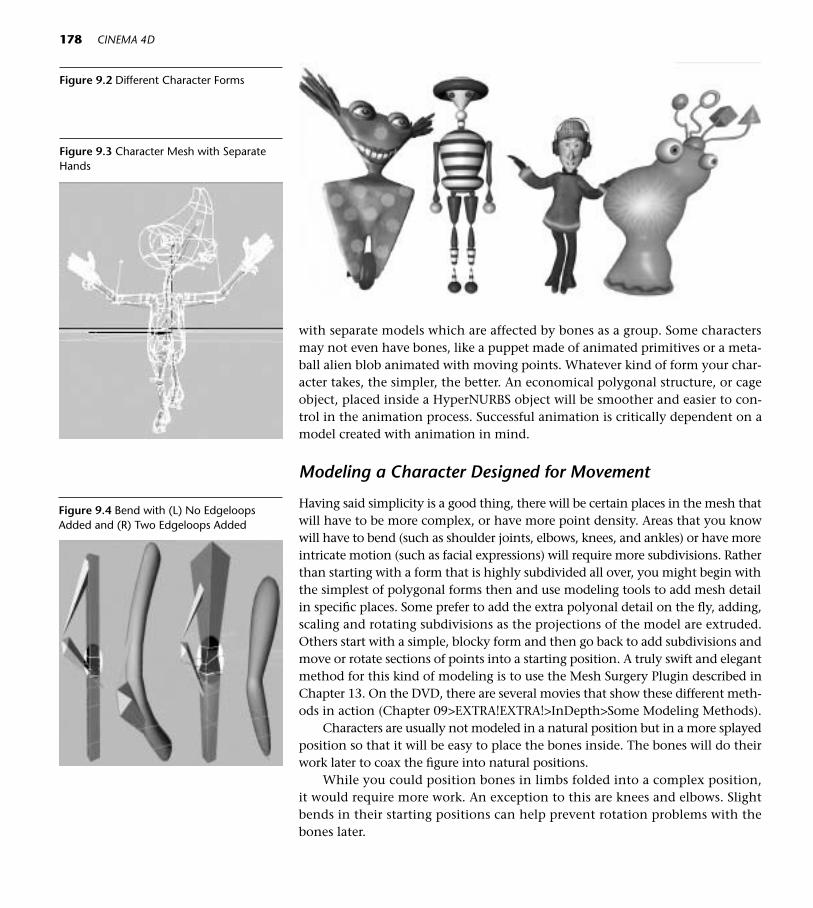
178 CINEMA 4D
Figure 9.2 Different Character Forms
with separate models which are affected by bones as a group. Some charactersmay not even have bones, like a puppet made of animated primitives or a meta-ball alien blob animated with moving points. Whatever kind of form your char-acter takes, the simpler, the better. An economical polygonal structure, or cageobject, placed inside a HyperNURBS object will be smoother and easier to con-trol in the animation process. Successful animation is critically dependent on amodel created with animation in mind.
Modeling a Character Designed for Movement
Having said simplicity is a good thing, there will be certain places in the mesh thatwill have to be more complex, or have more point density. Areas that you knowwill have to bend (such as shoulder joints, elbows, knees, and ankles) or have moreintricate motion (such as facial expressions) will require more subdivisions. Ratherthan starting with a form that is highly subdivided all over, you might begin withthe simplest of polygonal forms then and use modeling tools to add mesh detailin specific places. Some prefer to add the extra polyonal detail on the fly, adding,scaling and rotating subdivisions as the projections of the model are extruded.Others start with a simple, blocky form and then go back to add subdivisions andmove or rotate sections of points into a starting position. A truly swift and elegantmethod for this kind of modeling is to use the Mesh Surgery Plugin described inChapter 13. On the DVD, there are several movies that show these different meth-ods in action (Chapter 09>EXTRA!EXTRA!>InDepth>Some Modeling Methods).
Characters are usually not modeled in a natural position but in a more splayedposition so that it will be easy to place the bones inside. The bones will do theirwork later to coax the figure into natural positions.
While you could position bones in limbs folded into a complex position,it would require more work. An exception to this are knees and elbows. Slightbends in their starting positions can help prevent rotation problems with thebones later.
Figure 9.3 Character Mesh with SeparateHands
Figure 9.4 Bend with (L) No EdgeloopsAdded and (R) Two Edgeloops Added
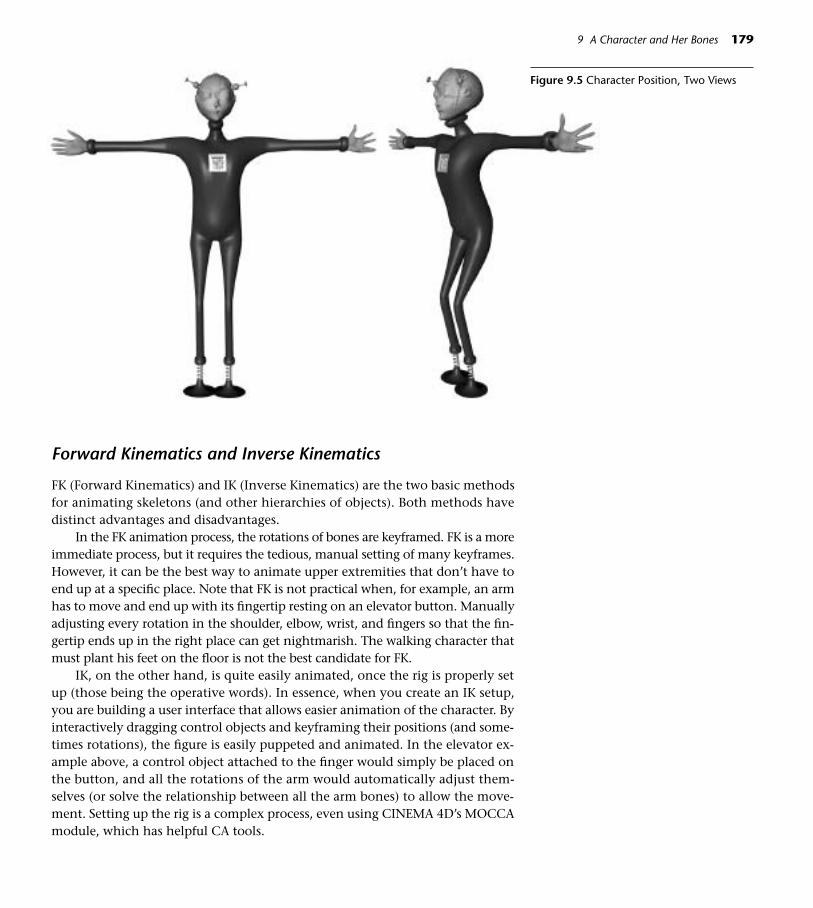
Forward Kinematics and Inverse Kinematics
FK (Forward Kinematics) and IK (Inverse Kinematics) are the two basic methodsfor animating skeletons (and other hierarchies of objects). Both methods havedistinct advantages and disadvantages.
In the FK animation process, the rotations of bones are keyframed. FK is a moreimmediate process, but it requires the tedious, manual setting of many keyframes.However, it can be the best way to animate upper extremities that don’t have toend up at a specific place. Note that FK is not practical when, for example, an armhas to move and end up with its fingertip resting on an elevator button. Manuallyadjusting every rotation in the shoulder, elbow, wrist, and fingers so that the fin-gertip ends up in the right place can get nightmarish. The walking character thatmust plant his feet on the floor is not the best candidate for FK.
IK, on the other hand, is quite easily animated, once the rig is properly setup (those being the operative words). In essence, when you create an IK setup,you are building a user interface that allows easier animation of the character. Byinteractively dragging control objects and keyframing their positions (and some-times rotations), the figure is easily puppeted and animated. In the elevator ex-ample above, a control object attached to the finger would simply be placed onthe button, and all the rotations of the arm would automatically adjust them-selves (or solve the relationship between all the arm bones) to allow the move-ment. Setting up the rig is a complex process, even using CINEMA 4D’s MOCCAmodule, which has helpful CA tools.
9 A Character and Her Bones 179
Figure 9.5 Character Position, Two Views

A Simple IK Example
This simple example of IK in action uses the standard tools in CINEMA 4D andwill introduce you to the feel of IK (without using MOCCA).
Step 1 Navigate to Chapter 09>C4D Files> Bubblegum.c4d. Save a workingcopy to your Models folder (File>Save As).
Step 2 Study the hierarchy and notice that Sphere 3 has an Anchor Tag that willprevent it and those below it from moving. Select the Effector object.
Step 3 Choose the IK tool from the left palette.
Step 4 With the Effector selected, drag the mouse around the screen. The ro-tation of all the pieces of Bubblegum is being decided by the positionof the Effector. Remove the Anchor Tag on Sphere 3 and see how thebehavior changes.
Now we will add an interesting twist by creating a Goal object for the Ef-fector to reach toward. This is a classic example of IK, as the position of the Goalor target will decide the position and rotation of the Bubblegum objects.
Had FK been used, each sphere would have been painstakingly rotated and thedestination of the top sphere would have been difficult to control. With the com-puter solving the rotations, there comes an inherent loose control. MOCCA’s SoftIK tools provide more bells and whistles for firmer management of the IK chain.
Step 5 Control-drag a copy of the Effector and move the copy to the top ofthe list, outside of the original hierarchy. Name the copy Goal.
Step 6 Cmd-click (right-click) on the Effector object in the Objects Manager,and choose New Expression>IK Expression. Drag the name Goal fromthe Objects Manager and drop it into the Target Object box in the At-tributes Manager Tag Properties.
Step 7 Using the Model and Move tools, drag the Goal around the screen. Movethe Goal side to side so the Bubblegum moves in a snakelike path, thenpull it out away from the Bubblegum and notice how the objects appearto stretch toward the Goal.
Creating Bones
In this exercise, we will create some bones using the standard version of CIN-EMA 4D (without the MOCCA Module).
Step 1 On the DVD, navigate to Chapter 09>C4D Files>Arm For Bones.c4d.Save a working copy titled Arm with Bones to your Models folder(File>Save As).
Step 2 Select the ARM object. Work in the Front view and Isoparms Display.Choose Edit>Frame Active Objects.
180 CINEMA 4D
Figure 9.6 IK Tool

Step 3 From the Deformer palette,choose the Add Bone Defor-mation icon. The bone isborn pointing its small endaway from you, so you needto go to the Coordinates Man-ager, enter a Rotation P valueof –90 and press Return (En-ter). Now the bone shouldhave its small end downward.
Step 4 With the Model and Movetools selected, use the blueMove handle to raise the topof the bone to the top of thearm.
Step 5 With the bone still selected,move the mouse on the upperblack arrow next to Length(under Object Properties) untilthe orange dot at the tip ofthe bone is at elbow position.
Step 6 With the bone still selectedand the Model and Move toolchosen, make sure only the Zlock icon has a line around itso that the bone is unable to flip around on the X or Y axes. Control-click on the orange dot and drag a new bone out of the first one, stop-ping at the top of the Left Hand Wrist bone.
Step 7 Save the file as Arm with Bones (File>Save or Cmd+S/Ctrl+S).
Influencing the Mesh with Bones
Step 1 Rename the top Bone as Left Upper Arm Bone, and the lower one (achild of the first one) as Left Lower Arm Bone.
Step 2 Make the Left Upper Arm Bone a child of the ARM object.
Step 3 Drag the uppermost bone of the hand, Left Hand Wrist, as a child ofthe Left Lower Arm Bone. (Don’t worry about any temporary weird-ness of the mesh position.)
Step 4 Select Left Upper Arm Bone, and from the Objects Manager Objectsmenu, choose Fix Bones. Click Yes to the Subobjects message.
Fix Bones sets the beginning position of the bones, something you alwayswant to do before starting to animate the bones. Reset Bones returns bones that
9 A Character and Her Bones 181
Figure 9.7 Bones Palette Icon Figure 9.8 Position of Bones
■ Shortcut: The Objects Menu canbe accessed as a contextual menu byCmd-clicking (right-clicking) on theobject name.

have been moved to the original Fixed position, and releases the binding of thebones to the mesh. By clicking Yes to the Subobjects message, the lower arm bonewas also fixed along with its parent.
Step 5 Save the file. Choose the Object tool and the Rotate tool, and select theLeft Lower Arm Bone. Move the mouse on the green Rotate handle tobend the arm. You’ll notice the elbow might be a little rumpled. Selectthe Left Upper Arm Bone and experiment with the Function values inObject Properties. One further down the list will help out the elbow.
There are two methods in the standard CINEMA 4D application to control thestrength of a bone on the mesh. Figure 9.9 (and the RangeLimitsAnimated.c4d filein Chapter 09>EXAMPLES on the DVD) shows the Range Limit method, useful foranimating minimum and maximum strengths of a bone. There is a PDF on theDVD for using the other method, Vertex Weights and Restriction Tags. In mostcases, MOCCA’s Claude Bonet weighting does the best (and easiest) job of this.
182 CINEMA 4D
Figure 9.9 Minimum and Maximum RangeLimits Influencing the Strength of a Bone ona Mesh

Introducing MOCCA
If you have the XL Bundle of CINEMA 4D or have purchased the MOCCA mod-ule, use these MOCCA tools to do the job.
Making Bones in MOCCA
Step 1 On the DVD, again navigate to Chapter 09>C4D Files>Arm For Bones.c4d. Save a working copy titled MOCCA FK to your Models folder(File>Save As). Click the Lay-out icon and MOCCA.
Step 2 Select the ARM object fromthe Objects Manager. Choosethe Bone Tool from the MOC-CA palette. Click on the Ac-tive Tool tab, and click theAdd Bone button. Using theCoordinates panel in the At-tributes Manager, drag thesmall upper black arrow nextto P.Y to position the bone atthe top of the arm. In the boxnext to R.P enter –90 andpress Return.
Step 3 Double-click the name Bone,and rename it Left Upper ArmBone. In the Attributes Man-ager, click the Object paneland drag the upper smallblack arrow next to Lengthuntil the tip of the bone iscentered in the elbow subdi-visions. Alternately, use theyellow interactive handlescreated by the Bone Tool in the Editor window tolengthen and rotate the bone.
Step 4 Make sure the Left Upper ArmBone is still selected. Control-click at the wrist (at the top ofthe Left Hand Wrist bone) tomake a new child bone. Re-name this bone Left LowerArm Bone.
Figure 9.11 Position of the Left Upper ArmBone Tip
9 A Character and Her Bones 183
Figure 9.10 MOCCA Layout
Figure 9.12 Left Lower Arm Bone Added>

Step 5 Select the Left Upper Arm Bone, and in the Active Tool tab, clickAdd/Update Null Bone.
This creates a Null Bone, sometimes referred to as a Root Bone, which won’taffect the geometry but can be used to control the rotation of its children. Re-name the new Bone object at the top of the hierarchy Left Arm Null Bone. TheNull Bone will take on the rotation of the Left Upper Arm Bone and will zero outthe rotational coordinates of the Left Upper Arm Bone.
Step 6 Make the Left Arm Null Bone (and its children tagging along behind)a child of the ARM.
Step 7 Open the HAND hierarchy, and drag the Left Hand Wrist object anddrop it as a child of the Left Lower Arm Bone.
Step 8 Select the Left Arm Null Bone, and choose Fix Bones before exiting theBone tool. Click the Yes button in the Subobjects input box.
The word Bone is included in the titles for these first looks at character set-ups, and all the words are spelled out. It’s easy to see which objects are bones bythe icon to the right of the name. Later, you’ll want to abbreviate words like Left,so a title of a bone might be only “L_Thigh.” Remember though, it is very im-portant that every object have a distinct title.
Claude Bonet
If you tried out Vertex Weights and Restriction tags (Chapter 09>EXTRA!EX-TRA!InDepth>VERTEXWEIGHTS.pdf on the DVD) you saw how each bone canbe weighted, or told which parts of the mesh to influence and how much. ClaudeBonet creates weighting too; it just does it in a more intuitive way.
Step 1 Work in the Perspective view. Select the Left Upper Arm Bone. From theMOCCA palette, choose the Claude Bonet tool. In the Active Tool tab,uncheck Only Modify Visible Elements and set the Strength to 30 per-cent. Paint the entire Arm and Hand, turning the object around andmaking sure you get in all the crevices.
Step 2 Now select the Left Lower Arm Bone, but this time paint only fromslightly above the elbow down to the fingertips. If you need tighterpainting control, reduce the radius of the brush in the Active Tool tab.
Step 3 Select the Left Hand Wrist Bone, and paint only from the wrist downto the fingertips.
Step 4 Choose the Rotate tool and rotate the Left Lower Arm Bone and thenthe Wrist Bone.
If the skins distorts, the painting of the mesh needs adjustment. Painting inthe distorted state can show you exactly where the problem is, and as you paint the
184 CINEMA 4D
Figure 9.13 Bone Tool
Figure 9.14 Claude Bonet Tool
Figure 9.15 Claude Bonet Map

mesh will correct itself. You can go back, select each bone, and repaint with theClaude Bonet tool. The coverage of the Claude Bonet painting may be extended(just select the bone again and paint more) or removed (hold down the Ctrl keyand paint), or the sliders in the Active Tool tab can be used to adjust the strength.Red X marks next to your bones mean that they are not affecting the mesh. ChooseFix Bones again and they will become functional. The Character project on theDVD has more in-depth information about using Claude Bonet.
Step 5 Save two copies of this file (File>Save As), one as MOCCA Arm FK andone as MOCCA Arm IK.
MOCCA Tools For Soft IK
MOCCA’s Soft IK tools add a natural “stretchability” and more control to char-acter rigs. Get to know MOCCA Soft IK by rigging this handy set of legs. Lateryou can expand them into a full figure, or attach them to any objects that mightsuddenly decide to run off. Be forewarned! This is a fairly tedious process. Onesmall detail left out or in the wrong place can stop the whole rig in its tracks. Dothis exercise when you are unhurried and feeling patient.
Step 1 Navigate to Chapter 09>C4D Files>Legs.c4d. Save a working copy toyour Models folder (File>Save As). Open the MOCCA Layout.
When the file opens, the HyperNURBS object is on so you can seethe form. Before you begin to work, click the green checkmark next tothe HyperNURBS to red so it won’t bog down your work. Claude Bonetmaps have already been painted. If you want to look them over, choosethe Claude Bonet tool and select each bone.
Step 2 Make sure Use IK is not on in the Plugins>MOCCA menu. Choose theMove tool.
Step 3 Command-click (right-click) on the Left Thigh Null Bone and chooseNew Tag>Soft IK Tag from the contextual menu.
Step 4 Command-click (right-click) on the Left Thigh Null Bone’s Soft IK tagand choose Copy Tag to Children from the contextual menu.
Step 5 Cmd-click (Ctrl-click) on the Pelvis Bone (not on its children) and chooseNew Tag>Stop Tag from the contextual menu. In the Attributes ManagerTag Properties, check Stop Generators. This tag will prevent the Hyper-NURBS from smoothing anything beyond the hierarchal level of the tag.
Step 6 Delete the Soft IK tags from the Left Suction Foot and from its children.
Step 7 Cmd-click (Ctrl-click) on the Left Suction Foot and choose New Tag>Stop Tag. In Tag Properties, check Stop Deformer. (This will prevent thebones from affecting the parts of the Suction Foot.)
9 A Character and Her Bones 185
Figure 9.16 Birthday Cake Legs

The Suction Feet will not be in the IK Chain, but because they willbe children of the Left and Right Shin Bones, they will inherit the mo-tion of the shins.
Step 8 Select the Soft IK tag for the Left Thigh Null Bone. On the Tag Prop-erties Pane in the Attributes Manager, check the check box for Anchor.
Step 9 Making sure the Soft IK tag for the Left Thigh Null Bone is no longer se-lected, Shift-click the Soft IK tags for Left Thigh Bone and Left ShinBone. In the Attributes Manager Rest panel, check Force Position. In theMOCCA Palette, click on Set Chain Rest Position and Set Chain Rest Ro-tation. (Use the cue at the bottom of the page until you get to know theMOCCA palette icons.)
Later, after moving the character around you can reset the IK chain back tothese original states. Just choose the uppermost bone that had Rest Position andRotation set originally, (in this case Left Thigh Bone) and click on the Soft IKTag. In the Attributes Manager Rest panel, click the button for Reset to Rest State.
Step 10 Select the Left Shin Bone and click on the Add Root Goal button in theMOCCA Palette.
Step 11 Drag the new Left Shin Bone.Root Goal object out of the hierarchy andplace it at the top of the Objects Manager list.
Step 12 Click on Left Shin Bone, and choose Add Tip Goal (a secondary choiceunder the Add Root Goal Button). Drag the the Left Shin Bone. TipGoal to the top of the list also.
Step 13 From the top menu, choose Objects>Null Object. Choose the Modeland Move tools. In the Editor window, position the null at the tip ofthe Left Shin Bone, checking it in the Front and Side views. (ChooseEdit>Frame Scene if you can’t see it.) Rename the Null Object as LEFTLEG CONTROLS.
Step 14 Drop both the Left Shin Bone.Root Goal and the Left Shin Bone. TipGoal into the LEFT LEG CONTROLS object as its children.
These goals will pull the root (Root Goal) and tip (Tip Goal) of theShin Bone towards them with the amount of strength you specify. AnIK setup is a delicate balance of tensions and counter-tensions. For ex-ample, if you move the Pelvis upward, the Tip Goal will exert pull onthe tip of the shin bone. The bone tip will always strive to reach its goal.If the Pelvis is lowered, the Shin Bone’s Root Goal (which is positionedbelow and out in front of the knee) will work to keep the knee point-ing toward it.
Step 15 Select the Left Thigh Bone (Be sure not to choose the Left Thigh NullBone by mistake) and choose Add UpVector. (Again, this a secondarychoice under the Add Root Goal Button.)
186 CINEMA 4D
Figure 9.17 Set ChainRest Position and SetChain Rest RotationIcons
Figure 9.18 Add Root Goal Icon (and Add Tip Goal, Add UpVector)
Figure 9.19 Leg Hierarchy

Step 16 In the Editor window, use the Move tool to position the Left ThighBone.Up out in front of and slightly above the Thigh Bone’s root. (TheRoot is the original point of the bone where it is widest.)
UpVectors provide more influence over the rotation of bones, asthe bone’s Y axis (by default, unless you change it to X) will strive toface the direction of the UpVector.
Step 17 Click on the Left Shin Bone Soft IK tag, and in the Attributes Managerconstraint pane set the Goal strength percent to 25. Select the Left ShinBone.Root Goal in the Objects Manager, and in the Editor window moveit slightly below and out in front of the knee. Select the Soft IK tag forthe Left Thigh Bone. On the Constraint pane, set the strength for Up-Vector to 75 percent.
Step 18 Cmd-click (right click) on the Left Thigh Null Bone and choose FixBones, clicking the Yes button for Subobjects.
Fix Bones establishes the relationship of the bones to the mesh. Ifyou want to reposition the bones later, select the topmost bone andchoose Reset Bones before you adjust the bones. Then choose Fix Bonesagain when the adjustments are complete.
In the Objects Manager, it’s critical that characters with multiple parts havea correct Hierarchal order or the HyperNURBS object will be making unnecessarydeformations. By using Null Objects and Stop Tags, the function of the Hyper-NURBS object can be controlled correctly.
Now is a good time to see if things are working. First, save the file so you canuse File>Revert to Saved in case things get disasterous while you are experimenting.
In the MOCCA menu, turn on Use Soft IK. In the Perspective view, use theMove tool to move the Left Leg Controls around. If your rig is not working, oneof those little details is afoul! Open the LegsRigged.c4d in the Ch09>Examplesfolder on the DVD and compare your rig item for item to find the culprit! Afteryou have finished experimenting, choose File>Revert to Saved to finish the rig.
Mirroring Bones
Step 1 Select the Left Thigh Null Bone in the Objects Manager, and choose Ob-jects>Reset Bones. (This will prevent the existing fixation values frombeing mirrored to bones on the opposite side.)
Click the Bone Mirror tool from the MOCCA Palette.
Step 2 In the Dialog box, set the Origin to Parent.
Step 3 Clear the text from the input box for Prefix.
Step 4 In the Replace input box, type Left and in the With box, type Right.
Step 5 Check the Auto Find Center box. In the Match Search box, a larger value(try 75 and experiment from there) will mirror the Claude Bonet mapswhen a low value will not.
9 A Character and Her Bones 187
Figure 9.20 IK Leg Rig
Figure 9.21 Bone Mirror Tool

Step 6 Click Mirror. Mirroring will take a few seconds. Click the Mirror but-ton only once. After you see the mirrored bones appear, close the Mir-ror Box.
Step 7 After mirroring the bones, select the Right Thigh Null Bone and chooseObjects>Fix Bones.
Step 8 Create a new Null Object and move it to the tip of the Right Shin Bone(Check Front and Side views). Name it RIGHT LEG CONTROLS and dropRight Shin Bone.Root Goal and Right Shin Bone. Tip Goal and (bothcurrently inside the LEFT LEG CONTROLS hierarchy) into it.
Step 9 Select the Right Thigh Null Bone and in the MOCCA palette, click SetChain Rest Position and Set Chain Rest Rotation.
Step 10 Save the File (File>Save or Cmd+S/Ctrl+S).
Creating a Pelvis Controller and Display Objects
Step 1 Choose a Null Object and place it at the position of the Pelvis Object.(Functions>Transfer). Name the Null Object PELVIS CONTROLLER.
Step 2 With the PELVIS CONTROLLER selected, Command-click (right-click)any of the letters P in the Attributes Manager Coordinates (in the left-hand Position column) and drag down to Animation>Set Driver.
Select the Pelvis object, and Command-click (right-click) on anyof the letters P (same column, Attributes Manager Coordinates panel)and drag to Animation>Set Driven (Relative).
Step 3 Select the PELVIS CONTROLLER again. Command-click (right-click)any of the letters R in the Attributes Manager Coordinates (Rotationcolumn) and drag down to Animation>Set Driver.
Select the Pelvis object, and Command-click (right-click) on anyof the letters R (same column, Attributes Manager Coordinates panel)and drag to Animation>Set Driven (Relative).
Step 4 Drop the Thigh UpVectors for both legs (Left Thigh Bone.Up and RightThigh Bone.Up) as children of the PELVIS CONTROLLER object.
Step 5 By changing the display of some of these tiny objects, you can makethem easier to see and set up a system of symbols for the kind of objectsthey are. Shift-click the LEFT LEG CONTROLS and RIGHT LEG CON-TROLS null objects. In the Attributes Manager Object Properties, chooseCube from the Display pull-down menu. Increase the Radius to 150 andthe Orientation to ZY. In the Basic Properties panel, choose Always fromthe Use Color pull-down and choose a color that will show up wellagainst your background.
See the example file LegsRigged.c4d in Chapter 09>EXAMPLES forthe colors and shapes applied to the Left Shin Bone. Root Goal and LeftThigh Bone.Up or make up your own system. In the Front view, check
188 CINEMA 4D
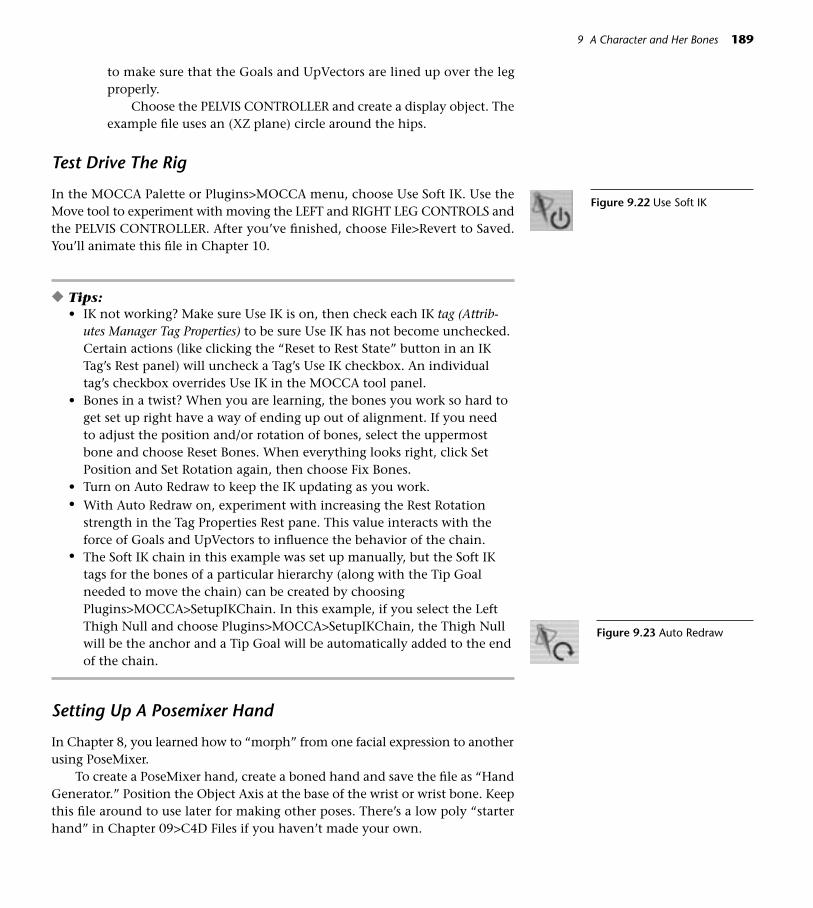
to make sure that the Goals and UpVectors are lined up over the legproperly.
Choose the PELVIS CONTROLLER and create a display object. Theexample file uses an (XZ plane) circle around the hips.
Test Drive The Rig
In the MOCCA Palette or Plugins>MOCCA menu, choose Use Soft IK. Use theMove tool to experiment with moving the LEFT and RIGHT LEG CONTROLS andthe PELVIS CONTROLLER. After you’ve finished, choose File>Revert to Saved.You’ll animate this file in Chapter 10.
◆ Tips: • IK not working? Make sure Use IK is on, then check each IK tag (Attrib-
utes Manager Tag Properties) to be sure Use IK has not become unchecked.Certain actions (like clicking the “Reset to Rest State” button in an IKTag’s Rest panel) will uncheck a Tag’s Use IK checkbox. An individualtag’s checkbox overrides Use IK in the MOCCA tool panel.
• Bones in a twist? When you are learning, the bones you work so hard toget set up right have a way of ending up out of alignment. If you need to adjust the position and/or rotation of bones, select the uppermostbone and choose Reset Bones. When everything looks right, click SetPosition and Set Rotation again, then choose Fix Bones.
• Turn on Auto Redraw to keep the IK updating as you work. • With Auto Redraw on, experiment with increasing the Rest Rotation
strength in the Tag Properties Rest pane. This value interacts with theforce of Goals and UpVectors to influence the behavior of the chain.
• The Soft IK chain in this example was set up manually, but the Soft IKtags for the bones of a particular hierarchy (along with the Tip Goalneeded to move the chain) can be created by choosingPlugins>MOCCA>SetupIKChain. In this example, if you select the LeftThigh Null and choose Plugins>MOCCA>SetupIKChain, the Thigh Nullwill be the anchor and a Tip Goal will be automatically added to the endof the chain.
Setting Up A Posemixer Hand
In Chapter 8, you learned how to “morph” from one facial expression to anotherusing PoseMixer.
To create a PoseMixer hand, create a boned hand and save the file as “HandGenerator.” Position the Object Axis at the base of the wrist or wrist bone. Keepthis file around to use later for making other poses. There’s a low poly “starterhand” in Chapter 09>C4D Files if you haven’t made your own.
9 A Character and Her Bones 189
Figure 9.23 Auto Redraw
Figure 9.22 Use Soft IK

Step 1 Navigate to Chapter 09>C4D Files>Hand Generator file. Choose Save As.Click the New Folder button and create a HANDS folder. Enter CUBE inthe title box and click Save to to save one unposed copy of the hand.Again, use Save As to save another copy named Base Pose.
Step 2 Repeat the Save As process with as many different poses as you want.Close the Hand Generator file.
Step 3 Open the Cube file. Select only the polygonal mesh inside the Hyper-NURBS object and choose Functions>Current State to Object. Drag thenewly generated Cube polygonal mesh up out of the original Hierar-chy. Throw away everything else in the file except the polygonal meshyou just created (including the bones). The polygonal object be at thebottom of the Hierarchy and will have a blue triangle icon to the rightof its name. All you will need in the PoseMixer file is the polygonal ver-sion of the hand, as the PoseMixer file will have its own HyperNURBSobject. Save the file.
190 CINEMA 4D
◆ Tips: • PoseMixer cares deeply about
the position and rotation ofobject axes. If posed objectshave axes in different positionsand various rotations, you’ll getoverall object movement andother weird behaviors when you use the sliders. By creatingall the poses from a Hand Gen-erator file, all the copies willhave common axis placement.If hands which have been cre-ated in separate files start mov-ing around in the PoseMixerfile, enter coordinates of 0,0,0(zero-ing out the axes) for every-thing in the file and then groupall the components into a Nullthat you can move anywhere.
• It’s easy for your PoseMixerAttributes to disappear as you go back to the Objects Managerto select poses. The lock on theupper right of the AttributesWindow will freeze the Attrib-utes for one object as you selectothers.
Figure 9.24 Hierarchy for PoseMixer Hand
Figure 9.25 Hand Poses

Step 4 Repeat Step 3 with the Base Pose, and rename the Cube in Base Pose asBase Pose.
Step 5 Open each pose file and use the bones to “strike the pose” before select-ing the Cube and choosing Current State to Object as in Step 3. Name theCube in each pose with a name describing the pose. Save each file.
Step 6 Create a new file and name it PoseMixer Hand. Choose File>Merge andimport the Cube, Base Pose, and all the poses into this new file.
Step 7 Choose a HyperNURBS object and drop the Cube object as its child.
Step 8 Turn off both visibility switches for the Base Pose and all the other ma-nipulated poses, but leave visibility of the Cube object on.
Step 9 From the MOCCA menu, choose PoseMixer. Make the PoseMixer ob-ject a child of the Cube. Select the PoseMixer object and in the Attrib-utes Manager, drag the name Base Pose from the Objects Manager intothe Default Pose box.
Step 10 Click the Add Pose button to add as many boxes as you need for theposes you created, and drop the names of the poses into the boxes.
Experiment with adjusting the sliders with different combinations, and savethe file.
As alternate methods, the hand poses can be created in one file and objectswith bones intact can be used. PoseMixer can also be used to morph Hierarchiesfor even more complex control of the hand. There is an excellent tutorial on thisat www.maxoncomputer.com in the Support section. Also, the MOCCA manualhas a more complex tutorial for a PoseMixer hand.
Character Shortcuts
If you made it through the Character.pdf, you may be in a state of shock over howmuch is involved in making a full Character rig. It does get better. Not only doesit get easier every time you go through the process, but also you will find ways totake shortcuts. For example, with similar characters you can make a copy of the fileand edit the character, using the same rig. There are some great plugins that pro-vide a ready-made rig that will slide right into your character, saving tons of setuptime. Check out Bonderland and Little Cup of MOCCA in Chapter 13>Plugins.There are example files of these on the DVD also. Paul Everett’s Visual Selector plu-gin adds ease to the rigging process.
Multiple Versions and States of Characters
A finished animation may appear to have one character, but behind the scenesthere may be hiding “multiple personalities.” For example, the main “mediumpoly,” fully rigged character with bones may be backed up by other versions thatfunction better in specific situations. A much lower poly version will work better
9 A Character and Her Bones 191
Figure 9.26 ”Frozen” Arm Position
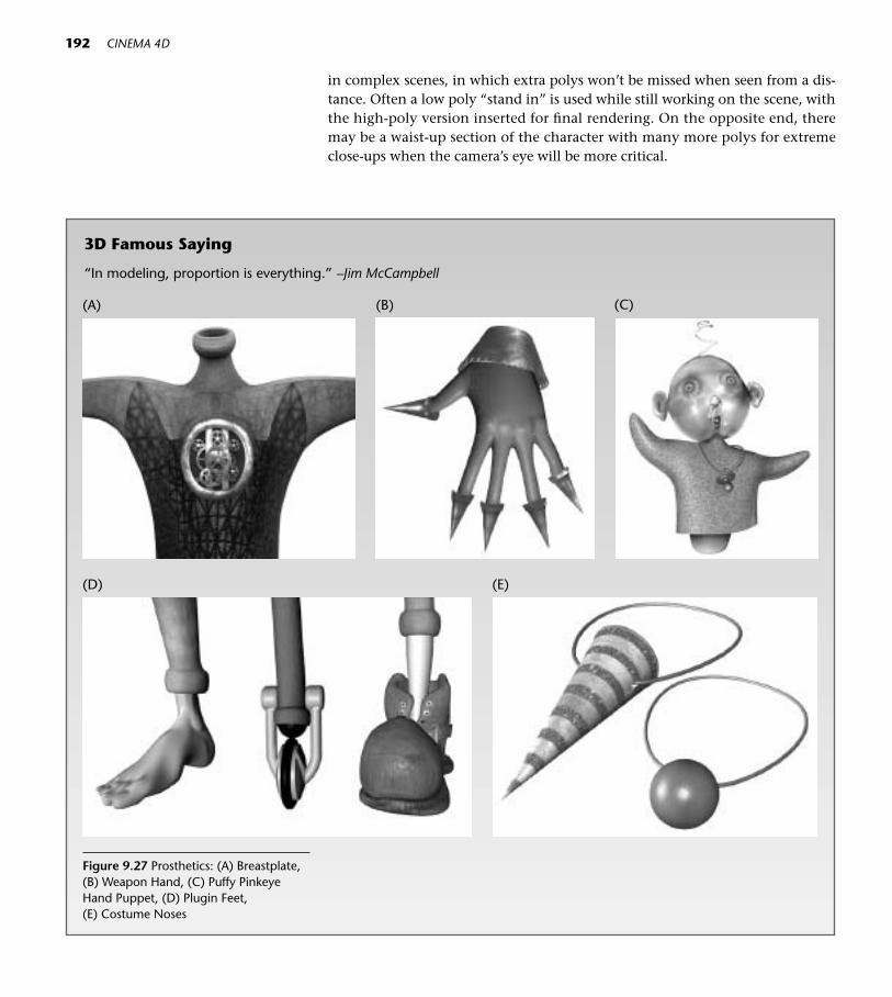
in complex scenes, in which extra polys won’t be missed when seen from a dis-tance. Often a low poly “stand in” is used while still working on the scene, withthe high-poly version inserted for final rendering. On the opposite end, theremay be a waist-up section of the character with many more polys for extremeclose-ups when the camera’s eye will be more critical.
192 CINEMA 4D
3D Famous Saying
“In modeling, proportion is everything.” –Jim McCampbell
Figure 9.27 Prosthetics: (A) Breastplate,(B) Weapon Hand, (C) Puffy PinkeyeHand Puppet, (D) Plugin Feet, (E) Costume Noses
(A) (B) (C)
(D) (E)

9 A Character and Her Bones 193
In certain poses in which parts of the figure will never move, the bones canbe used to nudge the pose into place, then frozen (current state to object) and thebones removed. There’s no need for the computer to keep up with bones that willnever be used.
Doing Your Character Homework
Let’s leave the technical behind for a while. With enough time and patience, any-one can learn the mechanics of animating a character. Even if a character hasachieved technical perfection, if it is one of an army of look-alike clones it will bringyou little attention. Thinly disquised rip-offs of movie characters seen by all, or thesame generic 3D face are simply not worth the trouble. Once again, it’s here thatsketchbook and pencil are more important than terabytes and megahertz.
Character Creativity
So, how do you come up with ideas? Chapter 20 is aboutmaking creative leaps.
Here are a few tips specific to Character Animation.
• Make time to observe people (or animals). Make men-tal notes about all their characteristics, differences andhabits.
• Collect details from life in your sketchbook—pages ofmouth expressions, funny ears, hands, noses from life,or a memory of someone you saw on the subway.
• Steal and incorporate. For example, go to nonhumansystems for details and forms, then brainstorm onways to use them in your character. Coiling tubesfrom the inside of an airplane might become a pros-thetic leg, fill a chestplate, or protrude from the topof a head.
• Invent! Fill your sketchbook with forms that you’venever seen before.
Figure 9.28 Prosthetic Wings

Practice in drawing from life is a tremendous asset to your character skills.Many community art centers have “model nights” when you can draw from themodel for a small fee. Study human and animal proportion generally and indi-vidually, then explore ways to exaggerate proportions into your own style.
Take time to study fields and subsystems that will add variety and believ-ability to your character work. Investigate things like makeup, symbols, hair de-sign, accessories, decorative elements from other cultures and times, old medicaltools, clockworks and machinery, even science and math.
Google Image will come in handy for research. Type in sunglasses, and pe-ruse the 50,000 styles. Explore crossover from field to field and system to sys-tem. Tattoo a microscopic diatom or celestial map on your character’s chest.
194 CINEMA 4D
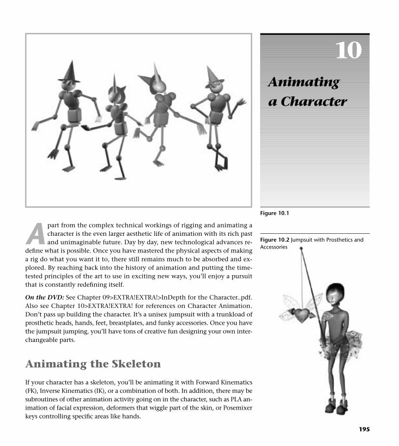
10Animating a Character
195
Figure 10.1
A part from the complex technical workings of rigging and animating acharacter is the even larger aesthetic life of animation with its rich pastand unimaginable future. Day by day, new technological advances re-
define what is possible. Once you have mastered the physical aspects of makinga rig do what you want it to, there still remains much to be absorbed and ex-plored. By reaching back into the history of animation and putting the time-tested principles of the art to use in exciting new ways, you’ll enjoy a pursuitthat is constantly redefining itself.
On the DVD: See Chapter 09>EXTRA!EXTRA!>InDepth for the Character..pdf.Also see Chapter 10>EXTRA!EXTRA! for references on Character Animation.Don’t pass up building the character. It’s a unisex jumpsuit with a trunkload ofprosthetic heads, hands, feet, breastplates, and funky accessories. Once you havethe jumpsuit jumping, you’ll have tons of creative fun designing your own inter-changeable parts.
Animating the Skeleton
If your character has a skeleton, you’ll be animating it with Forward Kinematics(FK), Inverse Kinematics (IK), or a combination of both. In addition, there may besubroutines of other animation activity going on in the character, such as PLA an-imation of facial expression, deformers that wiggle part of the skin, or Posemixerkeys controlling specific areas like hands.
Figure 10.2 Jumpsuit with Prosthetics andAccessories

Animating FK
When animating Forward Kinematics, joints are manually rotated and thenkeyframed.
When moving an arm for instance, you can rotate bones from the uppermostjoint down, keyframing each rotated joint as you go. If you have an arm andhand with continuous bones that will all move in one frame, you may work fromthe shoulder down, rotating shoulder, elbow, wrist, down to the outermost fin-ger joints. Once all the moving joints are rotated, you can then select the up-permost joint, choose the Select Children command and click the red Recordbutton to keyframe them simultaneously. AutoKeyframing can also be used torecord keys for FK. Remember the importance of setting starting state keys foreverything that will be moving. Let’s try out FK.
Step 1 Open the file Fortuneteller.c4d (Chapter 10>C4D Files). Save a work-ing copy to your Models folder (File>Save As). Open the Crystal Ballobject and turn off the visibility on the Hardware object for now.
Step 2 Before we animate the LEFT ARM with FK, we’ll flip-copy it to makethe RIGHT ARM, which we will animate with a different technique.
Step 3 In the Objects Manager, control-drag a copy of the LEFT ARM object.
Step 4 Choose Objects>Null Object. Drop the LEFT ARM copy into the NullObject as its child.
Step 5 Select the Null Object and in the Attributes Manager Coordinatespanel, enter a value of – (minus) 1 for S.X (X Scale) and press return.
Step 6 Drag the LEFT ARM copy out of the Null Object and rename it RIGHTARM. (You can throw the null away.)
Step 7 Open the RIGHT ARM Hierarchy and change all the “L”s to “R”s.
Step 8 Make both the LEFT AND RIGHT ARM objects children of the Manikinobject.
Scrub through the Timeline, and notice what the hands are doing. They wig-gle casually and then at the end (200 frames), they spread out more dramatically.We want the arms to begin with the hands resting (actually they will be tapping)on the table in front of the manikin, then passing over the crystal ball, and endingin the air as if revealing some mystery. There are two ways you can go about ani-mating an arm with FK. For the LEFT ARM, you will hand-rotate and set a keyframefor every joint manually. With the RIGHT ARM, you will set starting keyframes forall the joints, and then turn on Auto Keyframing so that a change in any joint atany point in time will be recorded.
The fact is, you will probably have to try this out several times to get the hangof it. Experiment with timing and combining different rotations on different jointsfor elegant motion. At this point, use the File>Save As command to save several
196 CINEMA 4D
■ Shortcut: The Select Childrencommand is a great candidate for acustom shortcut key, (such as Opt-Cor Alt-C). See the Appendix for in-structions on using the CommandManager to set custom Shortcuts.

versions so you can start over without having to remove keyframes. Have the An-imation Layout open, so it’s easy to pop down and remove keys that don’t seemto be working. If you do want to erase all the keys and start over, you can do so inthe Timeline.
◆ Tips: • Sometimes animation keyframes play hide and seek! Just when you
think you’ve removed all the offending keys and are ready to start over,some key somewhere is making something move! If the Timeline is in Auto-matic Mode (when the padlock is unlocked), Command-A and Delete willclear the animation. When the padlock symbol on the upper right sideof the Timeline is locked, (Manual Mode) only the keys for objects thathave been placed in the Timeline will respond to Timeline commandslike Command-A and Delete. Choosing Show All Animated from the Time-line Edit menu will place all keys in the Timeline, and Command-Afollowed by the Delete key will remove all animation.
• If your mesh is problematic around the elbows, you can always go backand adjust the bone functions, weight maps or work with the mesh itselfuntil it looks good!
• The axes of the sections of the arm are already placed at the properpoints of rotation for you. It’s important to know that if you create yourown jointed figures, you’ll need to make each section editable and moveeach axis to the point on which you want it to rotate. You’ll also need tomake each section a child of the object above it. The figure in the Primi-tive menu is already set up, so open it up and study its hierarchy andaxis placement as an example. It will also come in handy for more ani-mation practice.
• As your animation skills progress, you'll want to explore advanced tech-niques such as using Xpresso to control FK animation.
Step 9 Open the LEFT ARM hierarchy, and select L Upper Arm Bone, L LowerArm Bone, and L Wrist.
Step 10 On the right of the Animation Timeline, make sure Rotation is the onlytype of animation enabled.
Step 11 Making sure the current time is a 0 frames, click the Record button.
Step 12 Forward the current time to 25 frames, and working from the top bone(L Upper Arm Bone) down, rotate the joints into a position similar toFigure 10.3 B. Once you are happy with the pose, make sure you selectall joints that were rotated and record keyframes for each. (You can ei-ther Shift-select all the rotated bones, or select the uppermost bone,choose Objects>Select Children and then click the Record button forall at once.)
10 Animating a Character 197

198 CINEMA 4D
Figure 10.3 Fortuneteller Positions: A ) Starting Position, B) Second Position andC) Ending Position
Figure 10.4. Automatic Keyfram-ing Button
Step 13 At Frame 100, rotate the joints so that the hand is passing over the crys-tal ball. You’ll have to rotate the top joint outward, not just up, for thisto happen. Every time you change the pose, select any joints that werechanged and record keyframes.
Step 10 At Frame 180, pose the figure so that the spread hands have their palmsforward. As you get more accomplished at getting the movement youwant, try keyframing the hand in an arch at the end for a little addedmagic. (See the Example movie in Chapter 10>MOVIES/STILLS>For-tuneteller.)
Ready to try another method on the right side? Let the arm move basicallythe same but with some subtle differences in the motion.
Step 11 Close the LEFT ARM hierarchy, and open the RIGHT ARM hierarchy.Select the R Upper Arm Bone, R Lower Arm Bone, and R Wrist. OnlyRotation should still be enabled, so go ahead and click the Record but-ton to set a starting state key for all the joints at 0 frames.
Step 12 Forward the Timeline to 15 frames. Here we’ll turn on Autokeyframingso that anything that changes at any point in time will be keyframed.
Step 13 Create basically the same motion that you did before so that there willbe a general symmetry of the hands rising, but let the right arm andhand have some subtle differences from the left side.
All you have to do is move to a new point in time and make changes, repeat-ing those steps to the end of the Timeline. The red line around the editor windowreminds you that Autokeyframing is on. Be sure to turn it off when you are fin-ished. The frames you create can still be tweaked on the Timeline or in the F-Curvewindow.
There is a lot to be said for some planned asymmetry in animation. For ex-ample, you can see the movement you already created on the left arm as youwork. Stagger the times slightly where important things are happening. Notice
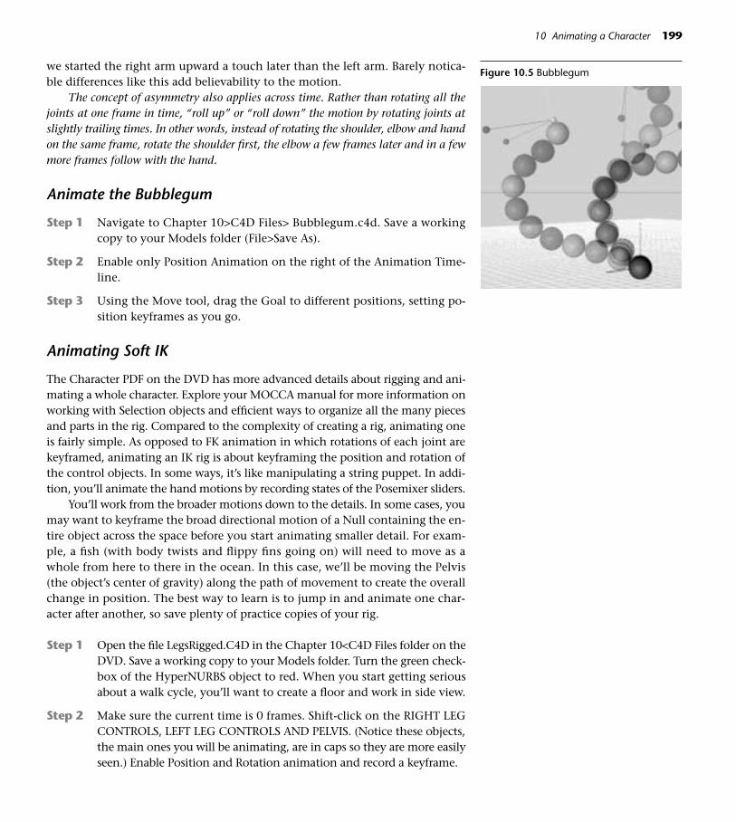
we started the right arm upward a touch later than the left arm. Barely notica-ble differences like this add believability to the motion.
The concept of asymmetry also applies across time. Rather than rotating all thejoints at one frame in time, “roll up” or “roll down” the motion by rotating joints atslightly trailing times. In other words, instead of rotating the shoulder, elbow and handon the same frame, rotate the shoulder first, the elbow a few frames later and in a fewmore frames follow with the hand.
Animate the Bubblegum
Step 1 Navigate to Chapter 10>C4D Files> Bubblegum.c4d. Save a workingcopy to your Models folder (File>Save As).
Step 2 Enable only Position Animation on the right of the Animation Time-line.
Step 3 Using the Move tool, drag the Goal to different positions, setting po-sition keyframes as you go.
Animating Soft IK
The Character PDF on the DVD has more advanced details about rigging and ani-mating a whole character. Explore your MOCCA manual for more information onworking with Selection objects and efficient ways to organize all the many piecesand parts in the rig. Compared to the complexity of creating a rig, animating oneis fairly simple. As opposed to FK animation in which rotations of each joint arekeyframed, animating an IK rig is about keyframing the position and rotation ofthe control objects. In some ways, it’s like manipulating a string puppet. In addi-tion, you’ll animate the hand motions by recording states of the Posemixer sliders.
You’ll work from the broader motions down to the details. In some cases, youmay want to keyframe the broad directional motion of a Null containing the en-tire object across the space before you start animating smaller detail. For exam-ple, a fish (with body twists and flippy fins going on) will need to move as awhole from here to there in the ocean. In this case, we’ll be moving the Pelvis(the object’s center of gravity) along the path of movement to create the overallchange in position. The best way to learn is to jump in and animate one char-acter after another, so save plenty of practice copies of your rig.
Step 1 Open the file LegsRigged.C4D in the Chapter 10<C4D Files folder on theDVD. Save a working copy to your Models folder. Turn the green check-box of the HyperNURBS object to red. When you start getting seriousabout a walk cycle, you’ll want to create a floor and work in side view.
Step 2 Make sure the current time is 0 frames. Shift-click on the RIGHT LEGCONTROLS, LEFT LEG CONTROLS AND PELVIS. (Notice these objects,the main ones you will be animating, are in caps so they are more easilyseen.) Enable Position and Rotation animation and record a keyframe.
10 Animating a Character 199
Figure 10.5 Bubblegum

Step 3 Move the current time to frame 5. Turn on the Automatic Keyframingbutton.
You don’t have to use Automatic Keyframing. The Record button can be clickedevery time an object is moved or rotated at a new point in time. It’s just so easy toforget! Also, the number of frames between keys determines how fast the steps are.These can be spread out or crunched together later as you adjust the timing.
Step 4 Select the RIGHT LEG CONTROLS, and choose the Move and Objecttools. Click the Use Soft IK button in the MOCCA palette. Drag themouse in the Editor window to move the right leg slightly up and for-ward. Don’t go overboard with the motion for now. (Motions thatpush the chain beyond a certain rotation will require other adjust-ments we want to avoid for now).
Step 5 Set the Current time to 10 frames. Select the PELVIS CONTROLLER andmove it forward with the green Move handle. Every time you plant afoot, the PELVIS CONTROLLER will need to be forwarded so that the cen-ter of weight stays over the planted foot.
◆ Tips: • Using the green, red and blue handles when positioning or rotating
LEG CONTROLS and PELVIS CONTROLLER can help you avoid someunplanned bone rotations.
• Remember that animating IK is not just about animating one object, butachieving a working tension between all the forces in the chain. As youstart working with rigs and see bones start to flip in unexpected ways,another object in the rig may need adjusting to allow the motion tooccur without unwanted spins. Spins and flips usually mean the chain isbeing pushed too far, so something has to give. That may mean chang-ing the strength values of one force, or adjusting the position or rotationof a Goal or UpVector. The Strength of Rest Rotations on the Soft IK Tag’sRest panel also interact with the other forces and can be adjusted.
Step 6 At 15 frames, select the RIGHT LEG CONTROLS and plant the foot onthe floor. Move the PELVIS CONTROLLER forward to maintain theweight over the foot. The PELVIS CONTROLLER can also be loweredon the Y axis when a foot plants to enhance the feeling of weight onthe foot.
Step 7 Once the right foot is firmly planted and the weight is centered overit, the left leg can be lifted slightly to the back (in the same frame ora few frames afterward).
Step 8 At this point, select the LEFT LEG CONTROLS and repeat the same steps:left leg up and forward, PELVIS CONTROLLER forward, right leg liftingto the back, left leg plants, PELVIS CONTROLLER rolls forward.
200 CINEMA 4D

● Springboard: From here, the way to success is “try, try again!” Every time the LegsRigged.c4d file is opened for a fresh start, use Save As to savea new working copy. After a smooth babystep walk is achieved, try addingmore personality to the movement by adding some side movement or ro-tation to the PELVIS CONTROLLER. From there move on to hops, jumps,stair climbs, turnarounds (the rotation of the LEG CONTROLS and even the Shin Root goals and Thigh UpVectors may have to be animated for thatone), hip-twisting boogies, slides and other increasingly interesting anddifficult motion! Before you know it, your characters will be turning flips!
To add further realism to the Suction feet, animate Bend deformers to curltheir front edges as they roll up off the floor.
On the DVD: For a truly authentic walk cycle, study stop frames photos of walk-ing bipeds and check out some of the excellent resource books on Character An-imation (Chapter 10>EXTRA!EXTRA!>References).
Using Set Driven Key to Bulge a Muscle
Navigate to the Chapter 10>EXAMPLES>Muscle.c4d. Click the Play button andwatch how the muscle “bulks up” when the elbow bends. After the rotation (Ro-tation on the H or Heading) is keyframed, Command-click (right-click) on theletter H in R.H in the Coordinates panel and drag over to Animation>Set Driver.
10 Animating a Character 201
Figure 10.6 Animated Legs
Figure 10.7 Bulging Muscle

202 CINEMA 4D
Putting Animation Principles To Work
You’ll see these time-tested concepts hard at work in any kind of animation—2D, 3D or stop-frame.
Knife a few extra cuts in the muscle area. Position the Bulge deformer on thearm and in the Objects Manager, and make the deformer a child of the arm.Then in Attributes Manager Object Properties, Command-click (right-click) onthe word Strength and slide over to Animation>Set Driven (Absolute). The de-gree of H rotation on the joint will control the size of the muscle.
• Readability What is behind your animatedcharacter? Is there a strongsilhouette so the audience canclearly read the shape and action?Uncluttered backgrounds in acontrasting value are best.
• Exaggeration Animation is Art. Therefore, you have a license to exaggerate. As a matter of fact, animationhappens so fast that exaggerationis often necessary for motion to be comprehended as normal.
• Clear Motivation Is the reason for an action clear?Think through what your charac-ter is feeling and thinking, so hisor her actions appear to comefrom within rather than from thecharacter being shuffled aroundby an animator.
• Arcs Watch some animation in slowmotion. Notice that everythingmoves on arcs rather than straight lines.
• Overlap In complex animation, one actiondoesn’t completely stop beforeanother starts, and stops andstarts happen at different times.The F-Curve window is extremelyhelpful in comparing the timing of different animated elements.
• Asymmetry Edit pairs or groups of matchingobjects for nuance. Throw thecomposition off balance. If youcan find a pair of eyeballs thesame size in a cartoon animation,you get the prize.
• Secondary Action Smaller actions that underscore a message. An expectant fatherpacing back and forth (primary)bites his nails (secondary).
• Anticipation A preliminary occurance that getsthe viewer primed for the mainaction. Tippi Hedron hears theflapping of bird wings—in itselfnot a bad thing, but a precursorof something scarier to come.
• Squash and Stretch When a character is squashed, the opposing dimensions arestretched so that volume ismaintained.
• Overshoot Most motion reads better if it goespast its destination and recoils.
• Follow-through The golf club doesn’t stop deadwhen it hits the ball but continueson in an arc. Apply the concept to character motion. When yourcharacter stops in his or her tracks,the hair keeps going.
• Continuing Motion Nothing is completely still. Evena character listening to anothermore active one will be displayingsubtle body language.

Animating with Posemixer
This one is easy. Select the Posemixer object in the Objects Manager. In ObjectProperties, just slide the sliders until you get the combination that creates thepose you want at a given point in time. Click the Record button. Go to the next place on the Timeline you want to set keys, and repeat the process.
Using F-Curves with Character Motion
Once your basic movement is in place, remember the power of F-Curves. Many of the Animation Principles (see ”PuttingAnimation Principles to Work”) can be directly affected inthe F-Curve window. Ease Ins and Ease Outs, exaggeration,arcs, timing, and other tweaks that make motion morebelievable can be controlled easily in this powerfulwindow.
Connect: Planting the Feet In Chapter 14 “A Jolt ofXpresso,” there is an expression for preventing yourcharacter’s feet from going through the floor.
Planning Motion
Getting a feel for timing and motion is one of the aspects of animation that mayor may not come intuitively. You may have to work at it. Being an animator islike being an actor, but with using a puppet.
Studying acting, dance, and choreography will add depth and excitement toyour work. Buy a stopwatch, and walk through motions, timing them for a roughidea of how long things take in real life. While you’ve been learning CINEMA 4D,your timeline has probably stayed on 90 frames most of the time. It’s time to stretchthat out so there is ample room for more manipulation of timing. After you havemastered the technicalities of making characters move, your next stop should beActing for Animators: A Complete Guide to Performance Animation, by Ed Hooks.
10 Animating a Character 203
Figure 10.8 PoseMixer Hand Poses
Figure 10.9 Stopwatch

This Page Intentionally Left Blank

11Cameras in Control
205
Figure 1.11
I t’s probably clear to you by now that the creation of a 3D world involvesmany integrated skills. You have already been trying on the roles of painter,sculptor, lighting director, and animator. Now it’s time to explore the work of
director and cinematographer. So far most of your work has been viewed throughthe Editor camera, a default view of the 3D space as seen in CINEMA 4D’s editorwindow. Since you didn’t have to create that camera, there was probably not evenmuch awareness about the role of the camera in the moviemaking process. Youcan create as many cameras as you need in C4D, and animate their position or ro-tations like any other 3D object. These virtual cameras have the same features astheir real-world counterparts, and those parameters (like focal length or depth offield) can be animated as well.
Artistically, the camera through which the scene is viewed is the ultimatecontrol over what your audience perceives. The virtual camera you create is thecritical eye, and therefore, it’s a good idea to set up cameras early in the processand edit everything in the scene to that camera’s eye. As the director, you areusing the camera as a tool, influencing your audience to regard the scene in aparticular way and feel a specific emotion. Ask yourself this important questionbefore you begin: What is it I want my audience to see and feel?
Looking through a Camera When you choose a Camera from the Lighting Menu, a new camera appears inthe editor. If you are in the Perspective view when you create the camera, it will
3D Famous Saying
“If it looks right, it is right.” —Jim McCampbell

be aligned the same as the Editor camera, and at that moment you are viewingthe scene from the camera’s view. However, if you choose Edit>Frame Scene orotherwise manipulate the editor view, you will no longer be looking throughthat new camera and will actually be able to look at it as an object in the scene.In this exercise, you’ll set up the view so you are looking through the camerayou create.
Create the Camera Object
Step 1 Open the file Poppers.c4d from the Chapter 11>C4D Files folder on theDVD. Save it as Poppers.c4d to your Models folder (File>Save As).
Step 2 From the top menu, choose Camera Object from the Lighting palette.Then choose Edit>Frame Scene from the View Menu. Use the mousewith the 2 and 3 keys to get a feel for the camera’s orientation in spaceand an understanding that you are not looking through the camerayou created, but at it.
Step 3 Double-click the Camera object in the Objects Manager and rename itMAIN CAMERA.
206 CINEMA 4D
The Camera Object
When you create a camera, the physical location and orientation is representedby a camera symbol. The X and Y axes of the camera correspond to the filmplane and the Z axis is the direction in which the camera is pointing. The pyra-mid of lines indicates the camera’s field of view, and the orange handles let youmake adjustments to the camera interactively.
Figure 11.2 Camera Icons
Figure 11.3 A Camera Object
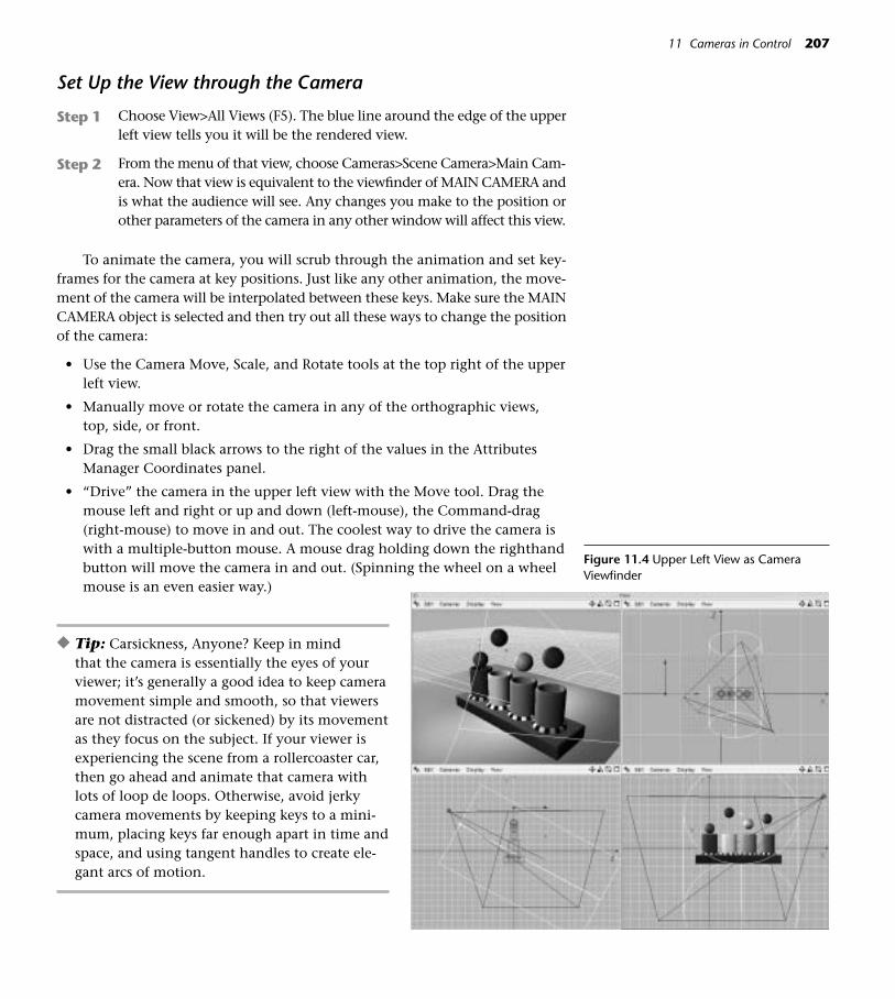
Set Up the View through the Camera
Step 1 Choose View>All Views (F5). The blue line around the edge of the upperleft view tells you it will be the rendered view.
Step 2 From the menu of that view, choose Cameras>Scene Camera>Main Cam-era. Now that view is equivalent to the viewfinder of MAIN CAMERA andis what the audience will see. Any changes you make to the position orother parameters of the camera in any other window will affect this view.
To animate the camera, you will scrub through the animation and set key-frames for the camera at key positions. Just like any other animation, the move-ment of the camera will be interpolated between these keys. Make sure the MAINCAMERA object is selected and then try out all these ways to change the positionof the camera:
• Use the Camera Move, Scale, and Rotate tools at the top right of the upperleft view.
• Manually move or rotate the camera in any of the orthographic views,top, side, or front.
• Drag the small black arrows to the right of the values in the AttributesManager Coordinates panel.
• “Drive” the camera in the upper left view with the Move tool. Drag themouse left and right or up and down (left-mouse), the Command-drag(right-mouse) to move in and out. The coolest way to drive the camera iswith a multiple-button mouse. A mouse drag holding down the righthandbutton will move the camera in and out. (Spinning the wheel on a wheelmouse is an even easier way.)
◆ Tip: Carsickness, Anyone? Keep in mind that the camera is essentially the eyes of yourviewer; it’s generally a good idea to keep cameramovement simple and smooth, so that viewersare not distracted (or sickened) by its movementas they focus on the subject. If your viewer isexperiencing the scene from a rollercoaster car,then go ahead and animate that camera withlots of loop de loops. Otherwise, avoid jerkycamera movements by keeping keys to a mini-mum, placing keys far enough apart in time andspace, and using tangent handles to create ele-gant arcs of motion.
11 Cameras in Control 207
Figure 11.4 Upper Left View as CameraViewfinder

Step 2 At Frame 0, drive the camera (using any of the methods listed above) tothe beginning view you want. Remember, it’s the upper left view thatcounts. Enable Position and Rotation animation, and click the Recordbutton. Or, animate the camera using the Attributes Manager Coordi-nates panel. Click any of the Ps and right- or Command-click to set a key-frame. Click any of the Rs and set a keyframe for Rotation also. Thesettings for Frame 0 in the example movie are: P.X 200, P.Y 1300, P.Z1400, R.H –132, R.P –30, and R.B left at 0.
Step 3 At Frame 90, adjust the camera in position and rotation for the end-ing view and set keyframes. (The example movie settings are P.X –700,P.Y 700, P.Z 2000, R.H –175, R.P –45 and R.B 3.) Be sure to save (File>Save or Cmd+S/Ctrl+S).
Step 4 Look at the animation path in the top view. Holding down the 2 key,drag the mouse right to left so you can see the entire path. Ouch—thatstraight line is a classic no-no in animation. In the Animation Layout,click the F-Curve tab. Drag the MAIN CAMERA object into the F-Curvewindow, choose Frame All, and select MAIN CAMERA>Position Z. Selectthe key at Frame 0, then Command-click (right-click) on it and chooseCustom Tangents>Soft Interpolation from the contextual menu. Raisethe right tangent handle so that the path is curved slightly, as in Figure11.5. Notice how the animation path is now an arc.
208 CINEMA 4D
Step 5 What if the colored balls were popping up out of the view, and youneeded to back up and take in more of the scene? The orange handles canbe used to adjust the focal length to a wider angle so they will be includedin the scene. Or, you could drag keys to new positions in the F-Curvewindow while keeping an eye on the scene in the editor window.
The interactive orange handles of the camera object can be usedto adjust focal length to a wider or narrower angle of view, affectinghow much is included in the scene. Changes in Focal length will dis-tort perspective, while moving the camera object keeps the perspective“normal” (or whatever perspective it is currently set to).
To animate focal length on a selected camera, scrub through the animationand set keyframes for the focal length at key positions. Click the Object panelin the Attributes Manager, and click on the object Focal Length. Drag the blackarrows and watch the editor window to see the value changes in action. Set key-frames where changes are necessary. Again, widely spaced, gradual changes aremore effective than too many sudden in and out movements.
Figure 11.5 Position Z F-Curve
Figure 11.6 Arc in Animation PathTop View

An Easier Way: Target Cameras
In the example above, you animated the position and rotation of the camera tokeep the subject in the view. Here’s a much easier way:
Step 1 Open the file StringofHands.c4d from the Chapter 11>C4D Files folder onthe DVD. Save it as HandsCam.c4d to your models folder (File>Save As).
Step 2 Select a Target Camera from the Lighting Palette.
Step 3 Click the Target tag to the right of the Camera object. In the AttributesManager, click the Tag panel and drag the object HAND 3 from the Ob-jects Manager into the box for Target Object. Choose View>All Views.
Step 4 In the upper left view, choose Camera>Scene Cameras>Camera. Choosethe Model tool and Move tool. In the orthographic views, use the blueand red Move handles to position the camera out in space and to theright, as in Figure 11.8. Set a keyframe for Position X, Y, and Z only.
11 Cameras in Control 209
Figure 11.7 Target Cam
Because rotation is determined by the camera’s relationship to the target ob-ject, it isn’t necessary to keyframe rotation.
Step 5 At Frame 200, working in the top view, use the red handle to swing theCamera around toward the Z axis and the blue handle to move the cam-era in close to the object.
Curses, foiled again! The target camera points specifically to the axis of thetarget object, which was placed at the top of the hanger so the hand could swingcorrectly from the string. To make the Target Camera head for a more central lo-cation on the hand, use this work-around.
Figure 11.8 Starting Position
Figure 11.9 Axis Too High

Step 6 Choose Objects>Null Object. Place the Null object in the middle of thehand’s palm, checking its position in several views, or use Functions>Transfer to get to the general vicinity, then adjust the position fromthere. Reselect the Target tag, and drag the Null Object into the TargetObject box. Now set a keyframe for a close-up of the hand.
Animating a Camera on a Spline Path
In this exercise, the camera will be placed on a spline path to move through anenvironment.
Step 1 Open the file MasterEnvironment.c4d from the Chapter 11>C4D Filesfolder on the DVD. Save it as Joyride.c4d to your Models folder. Workin All Views.
Step 2 Select a Camera from the Lighting Palette. In the View menu, chooseCameras>Scene Camera>Camera.
Step 3 Control-drag a copy of the Tunnel Path Spline object in the Objects Man-ager. Rename the copy Cam Spline.
Step 4 Command-click (right-click) on the Camera object and drag to NewExpression>Align to Spline expression. Select the Align to Spline tag,and in the Attributes Manager drag the object Cam Spline into the boxfor Spline Path. Check the check box for Tangential.
Step 5 With the current time at 0 Frames, click on the word Position in theAttributes manager and enter 0 percent as the value. Command-click(right-click) to set a keyframe. Around Frame 2500, keyframe the Po-sition value as 100 percent.
Step 6 Scrub though the animation and watch the upper left view. You’ll seeplaces where the spline path needs to be adjusted. Select the Cam Pathand the Points tool. Work with the motion of the camera in the ortho-graphic views by tweaking the position of points, converting hard pointsto soft, and adjusting tangent handles. Start with a close-up of the cur-rent camera position in the Top view to get a clear picture of how thecamera movement needs smoothing out, then go back and work in theother views if necessary.
A More Complex Camera Movement
The fly-through created above is fine for a quick joyride. Since the plan is to addinteresting objects to this museumlike space, the camera will need to slow downor look sideways occasionally. The viewer will need time to study objects in thealcoves lining the tunnel. This method offers more control over what the cam-era is looking at and for how long.
210 CINEMA 4D

11 Cameras in Control 211
Step 1 Open the file MasterEnvironment.c4d in the Chapter 11>C4D Filesfolder. Save a working copy to your Models folder (File>Save As).Choose Animation Layout.
Step 2 Choose a Target Camera from the Lighting palette.
Step 3 Set up the upper left view to be the “viewfinder” of the scene camera,and place the camera in a starting position at the entrace of the envi-ronment.
Step 4 Choose Objects>Null Object and drag the Camera’s target as a child ofthe Null. Place the Null where you want the camera to be looking first.
Step 5 Scrub through the scene, keyframing theposition of both the camera and the NullObject. (The Keys for the Null will be thepoints that you want the camera to stopand look at.) As you keyframe, you’ll beworking with the relationship betweencamera and target, moving both forwardin a leapfrog fashion. The rotation of thecamera will be determined by its fixationon the Null Object, so no Rotation key-framing is necessary.
◆ Tips:• Set up the scene camera in
the upper left view to use as a guide.
• Work in All Views.• Choose a brightly colored
and enlarged Display objectfor the Null Object, making it easier to see as you work.(In the Attributes Manager:Basic Tab>Use Color Alwaysand Object>Display.)
• To drive the camera forward,use the Move tool with theCommand-key (right-mouse)or try using the wheel on awheel mouse.
• Drop the Camera and theNull Object into the F-Curvewindow for fine tuning oftiming.
Figure 11.10 18mm Camera on a Spline Path
Figure 11.1150mmCamera on aSpline Path

Focal Length
Open the file BatInCave.c4d from the Chapter 11>C4D Files folder on the DVD.Select the Camera object. In the Attributes Manager Object Properties experi-ment with different values in the box for Focal Length (just drag on the blackarrows). A value of 50–52 is the equivalent of a normal lens on a real camera.Lower values, 45 and under, are in the Wide Angle range. A wide angle shot candistort slightly, adding a strange and dramatic feeling to the scene. Because thewide angle shot takes more in, it can also do more to establish a sense of place.Larger values are in the Telephoto range. They can create a sense of intimacy byfilling the frame with the subject, and they flatten perspective.
Animating a Camera on a Helix Spline Path
Here’s the easy way to circle an object, pulling the camera in tighter as you go.
Step 1 Open the file AlienPrincess.c4d from the Chapter 11>C4D Files folderon the DVD. Save a working copy to your Models folder (File>Save As).
Step 2 Select a Helix Spline from the Spline palette. Rotate the Helix 90º in Pitch.
Step 3 In the Attributes Manager, enter a Start Radius of 500.
Step 4 Create a Target Camera. Click the Target tag and and drag the Head intothe Target Object box.
Step 5 Command-click (right-click) on the Camera object and drag to NewExpression>Align to Spline expression. Select the Align to Spline tag,and in the Attributes Manager drag the object Helix into the box forSpline Path.
Step 6 With the current time at 0 Frames, click on Position in the AttributesManager and enter 0 percent as the value. Command-click (right-click)to set a keyframe. At Frame 350, keyframe the Position value as 100percent.
Step 7 Set the focal length of the camera to 22.
Step 8 Set up the camera as the scene camera in the upper left view; choose Win-dow>New View Panel and in that Editor View, rotate the Helix Spline sothat the last frame is a frontal close-up of the face. Adjust the height ofthe Helix to get the look you want.
Step 9 Open the F-Curve Manager. Drag the Align to Spline tag into the F-Curvewindow. Choose View>Frame All. Press Cmd+A (Ctrl+A) to select bothpoints, and choose Custom Tangents>Soft Interpolation and CustomTangents>Flat to create an Ease Out and Ease In.
212 CINEMA 4D
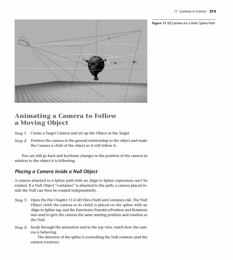
Animating a Camera to Follow a Moving Object
Step 1 Create a Target Camera and set up the Object as the Target.
Step 2 Position the camera in the general relationship to the object and makethe Camera a child of the object so it will follow it.
You can still go back and keyframe changes in the position of the camera inrelation to the object it is following.
Placing a Camera inside a Null Object
A camera attached to a Spline path with an Align to Spline expression can’t berotated. If a Null Object “container” is attached to the path, a camera placed in-side the Null can then be rotated independently.
Step 1: Open the File Chapter 11>C4D Files>NullCamContainer.c4d. The NullObject (with the camera as its child) is placed on the spline with anAlign to Spline tag, and the Functions>Transfer>(Position and Rotation)was used to give the camera the same starting position and rotation asthe Null.
Step 2: Scrub through the animation and in the top view, watch how the cam-era is behaving.
The direction of the spline is controlling the Null rotation (and thecamera rotation).
11 Cameras in Control 213
Figure 11.12 Camera on a Helix Spline Path

Step 3: Scrub back through the animation and keyframe independent rotationsfor the camera object. Enable Rotation Animation. At Frame 40, click theRecord button to set a starting key. At Frame 35, adjust the R.H valueso the camera turns its gaze to the blue cube. Record a key.
Using Depth of Field
Photographers often blur the foreground and background to focus attention ona specific object.
This shallow depth of field can calso be created with a virtual camera inCINEMA 4D.
Step 1 Open the file DOFPoppers.c4d from the Chapter 11>C4D Files folderon the DVD. Save a working copy to your Models folder (File>Save As).
Step 2 The camera has already been created, placed, and chosen as the scenecamera in the top left view. Select DOF Camera in the Objects Manager.
Step 3 Select the DOF Camera in the Objects Manager. In the Attributes Man-ager, click the panel for Depth. Check the check boxes for Front and RearBlur. Leave the Start value at 0 and enter an End value of 2000 for bothFront and Rear.
Step 4 Open the Render Settings. Click the Effects page, and check Depth ofField. Make sure Enable Post Effects is checked. Click Depth of Field tobring up the pages for editing.
Step 5 Click on the Basic panel. Enter a value of 30 percent for Blur Strength.Check on Use Distance Blur and enter a value of 20 percent. Close theRender Settings and render a movie.
214 CINEMA 4D
◆ Tip: Depth of Field is a postren-dering effect and will be addedafter the initial rendering of eachframe.
Figure 11.13 Camera Set for Shallow Depthof Field

Virtual Lens and Filter Effects
The virtual counterparts of diffusers, fisheye lenses, vignettes, and just about anyother real-life lens or filter effect can be easily emulated in 3D. Just make a lensfrom a primitive, apply a material that copies the properties of the real thing, andplace the object in front of the virtual camera. For a vignette, use an alpha chan-nel. A fisheye lens has a high refraction that can be emulated with a material. Al-though they are much easier to accomplish in AfterEffects, even transitions couldbe faked by animating materials or lights between scenes.
Switching Cameras in CINEMA 4D
To be honest, most people create different camera renderings and then compos-ite them with sound and effects in a compositing application. You’ll learn moreabout compositing in Chapter 19. You can switch from camera to camera in a sin-gle CINEMA file. Here’s how:
Step 1 Open the file Switching Cameras.c4d from the Chapter 11>C4D Filesfolder on the DVD. Save a working copy to your Models folder(File>Save As).
Step 2 Choose Objects>Scene>Stage. In the Attributes Manager, click the Ob-ject panel.
Step 3 At Frame 0, drag the Floor Level Cam into the Camera box. Click theword Camera and set a keyframe.
Step 4 At Frame 50, drag the Low, Close Cam into the Camera box and set akeyframe. Scrub the Timeline to see the cameras change.
You can add as many cameras as you want. You can also use the Stage Ob-ject to switch Skies, Backgrounds, Foregrounds, and Environments.
A CriticalDistinction
Remember there is an important differ-ence between moving a camera in rela-tion to the subject and zooming thecamera by changing its focal length.Moving the mouse while holding downthe 2 key now moves the camera whileCmd+2 and moving the mouse changesthe focal length. While moving a cam-era closer and zooming in may look very
11 Cameras in Control 215
Figure 11.14 Zoomed Views

much the same through the camera viewfinder, there is an artistic difference.Moving the camera does not distort perspective. A camera zoomed back from asubject creates emphasized perspective, while zooming into telephoto range alsodistorts with an overly flattened effect. Either extreme can be used to create aunique look for a shot.
Looking through Other Objects
Occasionally it can be helpful to look at the scene from the point of view of anobject or light. Select the object you want to look through, and choose Cam-eras>Link Active Object from the View menu.
On the DVD: Check the Chapter 11>EXTRA!EXTRA! folder for other resources oncamera work and filmmaking.
216 CINEMA 4D

12The Art ofRendering
217
Figure 12.1
T he worlds you have created in a virtual 3D space and framed in the eye ofa camera must now be rendered to create a final product. In layman’s lan-guage, the computer paints a picture of the view through the camera for
a still image or each sequential frame of a movie. The rendering can aim to sim-ulate the look of the real world with photographic clarity, taking into accountlighting, reflections, shadows, and all the other influences of the environment.Alternately, the scene can be rendered with sytlistic or even painterly strokes.The process of rendering is a delicate balance of the quality you must have withthe time it takes to render the project. By getting to know render settings, youcan make the best use of your time and achieve the level of quality appropriatefor your project.
Rather than restating the manual on the specifics of every setting, this sec-tion will explore some of the most helpful uses of basic settings for the right bal-ance of productivity and quality. In addition, it will focus on rendering methodsthat enhance the artistry of your work in CINEMA 4D.
On the DVD: Projects that require the installation of the optional Advanced Ren-der module are on the DVD. See the Chapter 12>EXTRA!EXTRA!>InDepth>AD-VANCED RENDERING folder for the PDF files.
■ Shortcut: To access the Render Settings from the keyboard, press Ctrl+B.
Figure 12.2 Rendering Icons: Render ActiveView, Render in Picture Viewer and RenderSettings

Investigating Render Settings
When you click the Render Settings Icon, a dialog box with ten tabs appears.Let’s look at the significance of the most commonly used settings.
The General Tab
Antialiasing
With this setting on None, the corners of pixels on the edges of objects will benoticable as “the jaggies.” When you are test-rendering, None is fine and willsave time. Depending on your need for smooth edges in the final rendering ofthe project, you may want to choose Better quality of Geometry or highest qual-ity of Best. These settings oversample, or make more (and smaller) pixels for asmoother edge. Naturally, the higher quality settings take longer to render.
Check the Filter pulldown menu. If you are rendering a still, choose the StillImage filter for a cleaner edge. For movie frames, choose the Animation filter,which will yield a softer edge less prone to flickering. For even more control,click the Antialiasing tab.
218 CINEMA 4D
Render As Editor
When test-rendering animation, you are often more concerned with how the mo-tion looks as opposed to the quality of the surfaces or the effects of lighting. Bychecking the Render As Editor box, you can rapidly render one of the less time-in-tensive editor displays (Isoparm, for example) and still have all the informationyou need about the animation.
Transparency, Reflection, Shadow
These pulldown menus allow you to turn off or limit the rendering of these time-intensive features. When you are test-rendering, seeing these may not be criti-cal and turning them off temporarily can speed up the rendering process.
Figure 12.3 Antialiasing , None (L) and Best (R)
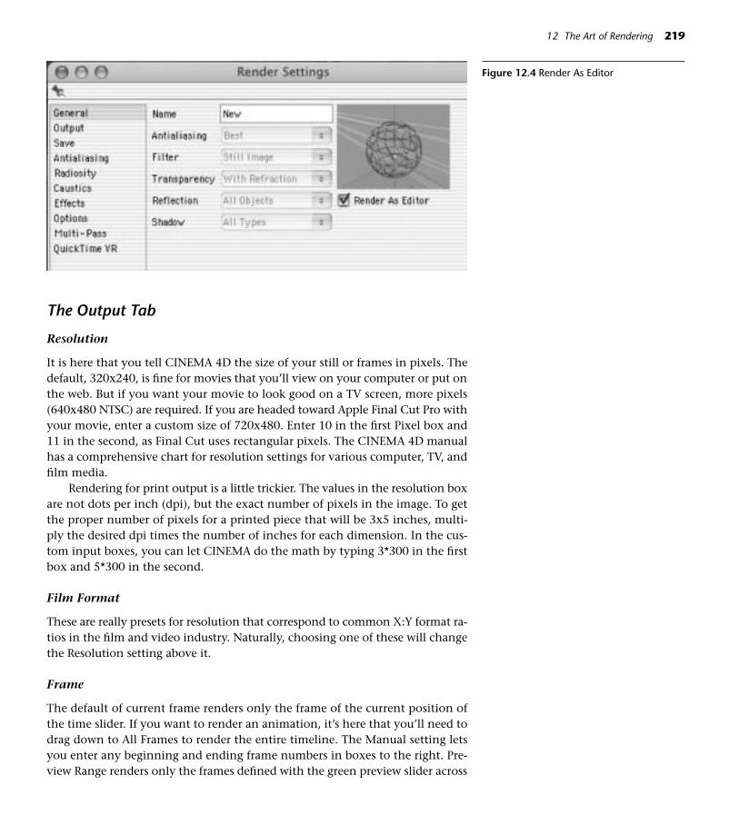
The Output Tab
Resolution
It is here that you tell CINEMA 4D the size of your still or frames in pixels. Thedefault, 320x240, is fine for movies that you’ll view on your computer or put onthe web. But if you want your movie to look good on a TV screen, more pixels(640x480 NTSC) are required. If you are headed toward Apple Final Cut Pro withyour movie, enter a custom size of 720x480. Enter 10 in the first Pixel box and11 in the second, as Final Cut uses rectangular pixels. The CINEMA 4D manualhas a comprehensive chart for resolution settings for various computer, TV, andfilm media.
Rendering for print output is a little trickier. The values in the resolution boxare not dots per inch (dpi), but the exact number of pixels in the image. To getthe proper number of pixels for a printed piece that will be 3x5 inches, multi-ply the desired dpi times the number of inches for each dimension. In the cus-tom input boxes, you can let CINEMA do the math by typing 3*300 in the firstbox and 5*300 in the second.
Film Format
These are really presets for resolution that correspond to common X:Y format ra-tios in the film and video industry. Naturally, choosing one of these will changethe Resolution setting above it.
Frame
The default of current frame renders only the frame of the current position ofthe time slider. If you want to render an animation, it’s here that you’ll need todrag down to All Frames to render the entire timeline. The Manual setting letsyou enter any beginning and ending frame numbers in boxes to the right. Pre-view Range renders only the frames defined with the green preview slider across
12 The Art of Rendering 219
Figure 12.4 Render As Editor

the Timeline ruler. Use one of these two options to zero in on the specific partof the animation you are currently tweaking to save lots of rendering time.
Field Rendering
To be safe, check with your client about their requirements. Also, stay away fromcompression that might destroy field-rendered images.
The Save Tab
Path
Click the Path button and navigate to the location where you want to save thefile. If you want to create a folder as a container for frames, click the New Folderbutton and name the folder. Sometimes, however, it you are working on a proj-ect that is requiring lots of tests, it may be more efficient to create a template file(place it into the same folder with the C4D application) with a default title oftest and default location of Desktop. Continue to replace that test file on thedesktop until you get a keeper, then just rename and file the final file.
Format
The default format is TIFF. When you are rendering an animation, it is importantthat you either 1. create a folder (see Path above) for the TIFF frames, or 2. dragdown to one of the QuickTime choices. If you fail to do so, you’ll be doing someserious housekeeping with all the TIFFs that get splattered all over your desktop.QuickTime movie renders an acceptably compressed movie, QuickTime Small usesmore compression for the web (with significant quality loss) and QuickTime Bighas no compression. Note that CINEMA 4D offers an impressive list of formats forstills and still frames. If you create a template c4d file, (as discussed previously underPath), you could choose QuicktTime format as permanent insurance against for-getting to set the format for an animation and littering the desktop with TIFFs.
Name
This option offers numbering styles for numbered sequences.
Alpha
Click this check box to render a file with a clear background. This file will popright into a compositing program like Adobe After Effects, or other applicationslike Apple Final Cut Pro and Adobe Photoshop. The model will have perfectlyclean edges and slide right in over other layers placed in the composite. The AfterEffects Project File option will be covered in Chapter 19. The Save button at thebottom refers to saving an After Effects file and is not required to save the gen-eral render settings! The Radiosity and Caustics tabs will be covered in PDFs onAdvanced Rendering on the DVD.
220 CINEMA 4D
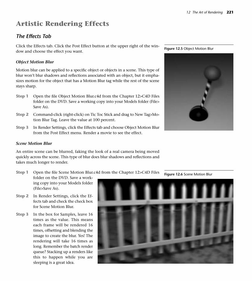
Artistic Rendering Effects
The Effects Tab
Click the Effects tab. Click the Post Effect button at the upper right of the win-dow and choose the effect you want.
Object Motion Blur
Motion blur can be applied to a specific object or objects in a scene. This type ofblur won’t blur shadows and reflections associated with an object, but it empha-sizes motion for the object that has a Motion Blur tag while the rest of the scenestays sharp.
Step 1 Open the file Object Motion Blur.c4d from the Chapter 12>C4D Filesfolder on the DVD. Save a working copy into your Models folder (File>Save As).
Step 2 Command-click (right-click) on Tic Toc Stick and drag to New Tag>Mo-tion Blur Tag. Leave the value at 100 percent.
Step 3 In Render Settings, click the Effects tab and choose Object Motion Blurfrom the Post Effect menu. Render a movie to see the effect.
Scene Motion Blur
An entire scene can be blurred, faking the look of a real camera being movedquickly across the scene. This type of blur does blur shadows and reflections andtakes much longer to render.
Step 1 Open the file Scene Motion Blur.c4d from the Chapter 12>C4D Filesfolder on the DVD. Save a work-ing copy into your Models folder(File>Save As).
Step 2 In Render Settings, click the Ef-fects tab and check the check boxfor Scene Motion Blur.
Step 3 In the box for Samples, leave 16times as the value. This meanseach frame will be rendered 16times, offsetting and blending theimage to create the blur. Yes! Therendering will take 16 times aslong. Remember the batch renderqueue? Stacking up a renders likethis to happen while you aresleeping is a great idea.
12 The Art of Rendering 221
Figure 12.5 Object Motion Blur
Figure 12.6 Scene Motion Blur

Cel Rendering
The cel rendering options in the Effect tab offer some interesting graphic inter-pretations of your scene. Click the Effects tab and Choose Cel Rendering fromPost Effects. Open any of your previous files and experiment with different set-tings in the Basic Properties Settings.
Multipass Rendering
This option is a powertool if you are compositing your CINEMA 4D renderingsin applications such as Adobe Photoshop or After Effects. Multipass allows youto render different artistic possibilities at one time, and then have more controlover the separated layers in the compositing program. This opens up so manycreative possibilities, it can make your head spin.
Step 1 Open the file Multipass.c4d from the Chapter 12>C4D Files folder onthe DVD.
Step 2 In Render Settings, click the Multipass page.
Step 3 Study the settings. Channels for Specular, Material Color, and Reflec-tion have been enabled. Also, All is chosen in the Separate Lights menu.The format is Photoshop.
Step 4 Now, if you have Photoshop, open Multipass Render.psd from the Chap-ter 12>STILLS/MOVIES folder. Everything is neatly separated in yourLayers palette. It would be easy to omit a light or apply a Hue change orPhotoshop Layer Styles to any of the layers.
222 CINEMA 4D
Figure 12.7 Cel Rendering 1 Figure 12.8 Cel Rendering 2 Figure 12.9 Cel Rendering 3
Figure 12.10 Multipass

Rendering a QuickTime VR Movie
A QuickTime VR is a movie that the viewer can explore interactively with a mouse.
Step 1 Open the file QuickTime VR.c4d from the Chapter 12>C4D Files folderon the DVD. Press F5 for all views and notice the placement of thecamera.
Step 2 In Render Settings, click the Save tab. Click the Path tab and set up thelocation for the rendered file.
Step 3 In the Format pull down menu, drag down to QuickTime VR Object.Press Shift+R to render the frames. (It’s normal that the first frames ofthe rendering will be all black.)
Step 4 When you play the movie in QuickTime, drag the hand to navigatethrough the space.
On the DVD: If you have the Advanced Rendering Module installed, be sure tocheck the Chapter 11>EXTRA!EXTRA!>InDepth>ADVANCED RENDERING folderfor projects that explore Radiosity, Caustics, Glows and Highlights, and HDRI.Even if you don’t have the module, look at the examples of the kinds of thingscan be done with this powerful option.
12 The Art of Rendering 223
Figure 12.11 Fives Rendered with Radiosity

This Page Intentionally Left Blank
13Plugins
225
Figure 13.1
W hen an application as solid, intuitive, and powerful as CINEMA 4D hasa user community rich with talented and generous third-party pro-grammers, it’s a win-win situation for all. Support these individuals by
paying them for their reasonably priced commercial wares, and reward their free-ware with thank-yous, attaboys, and donations. Plugins are snippets of program-ming, minitools that do specific jobs and infuse new creative ideas. Most ofteninstantly downloadable, CINEMA 4D plugins range from free to reasonably priced.Some of the add-ons discussed in this chapter are not actually plugins, but mod-ules or standalone helper applications. After reading these descriptions of what youcan do artistically with these, check the DVD for tutorials, example files, and a URLlist of resources. Be sure to visit the Plugin Café at www.maxoncomputer.com, themotherlode for C4D plugins and other resources.
Installing Plugins
• Quit CINEMA 4D before installing plugins.
• Review the Read Me file for any specific instructions.The usual procedure for installing plugins is to dropthe entire folder holding the plugin and its accompa-nying files into the Plugins folder (inside the folder foryour current version of C4D).
• The plugin should then appear in the C4D Pluginspulldown from the top menu. Yet another reason toread the Read Me file is that some plugins have fea-tures in additional locations, so you may need somedirections to those locations.

Commercial Plugins
Mesh Surgery
Mesh Surgery from Paul Everett and Per-Anders Edwards never fails to make anymust-have C4D plugins list. This turbocharged suite of modeling tools empow-ers the crafting of meshes in ways you haven’t even dreamed of. Mesh Surgeryis packed with tools that can subdivide and manipulate the mesh in innovativeways. Be sure to check out the PDF, and then head over to www.tools4d.com forthe grand tour, including excellent manuals and videos of the plugin in action.Here’s a quick peek at just a few of the many features:
• The Scapel. Here’s something everyone has wished for—you can use theScalpel to cut through visible polys without affecting the surrounding mesh.
• Katana. With this tool you can create Edge Loops, a modeling techniquethat provides more naturally movable polygonal structure around organicforms.
• Superflange. This feature allows you to subdivide a HyperNURBS meshwhile keeping a rounded quality in the form. (If you knife a HyperNURBSobject close to the edge it flattens out the form requiring you to go backand push in the points to round off the shape.) With Katana and Super-flange, you can quickly create cuts around the mesh and pull them out toround out the form on the fly.
• Hinge tools. These tools provide numerous ways to transform polygons.For example, you can rotate a selection of polys on one edge and extrudethem upward.
• Soft Selections. Soft selections apply a falloff to the edge of selected polysyou are transforming so the mesh can be pushed and pulled much moreorganically.
226 CINEMA 4D
Figure 13.2 Scapel Example
Figure 13.3 Katana
Figure 13.4 Superflange
Figure 13.5 Hinge Extrude
Figure 13.6 Mesh Brush“ Clay Sculpted”
Figure 13.7 Mesh Brush“ Hair Brush”
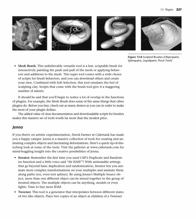
• Mesh Brush. This unbelievably versatile tool is a fast, scriptable brush forinteractively painting the push and pull of the mesh or applying behav-iors and additions to the mesh. This super tool comes with a wide choiceof scripts for brush behaviors, and you can download others and createyour own. Combined with Soft Selection, this tool emulates the feel ofsculpting clay. Scripts that come with the brush tool give it a staggeringnumber of talents.
It should be said that you’ll begin to notice a lot of overlap in the functionsof plugins. For example, the Mesh Brush does some of the same things that otherplugins do. Before you buy, check out as many demos as you can in order to makethe most of your plugin dollars.
The added value of clear documentation and downloadable scripts for brushesmakes this massive set of tools worth far more that the modest price.
Jenna
If you thrive on artistic experimentation, David Farmer at Cidertank has madeyou a happy camper. Jenna is a massive collection of tools for creating and an-imating complex objects and fascinating deformations. Here’s a quick tip-of-the-iceberg look at some of the tools. Visit the galleries at www.cidertank.com formind-boggling insight into the creative possibilities of Jenna.
• Iterator. Remember the first time you used C4D’s Duplicate and Random-ize function and a little voice said “Ah HAH!”? With animatable settingsthat go beyond basic duplication and randomization, Iterator lets you ani-mate more complex transformations on your multiples and animate themalong paths (yes, even text splines). By using Jenna’s Multiple Source ob-ject, more than one different object can be mixed together in the group ofiterated objects. The multiple objects can be anything, models or evenlights. Time to buy more RAM.
• Tweener. This tool is a generator that interpolates between different statesof two like objects. Place two copies of an object as children of a Tweener
13 Plugins 227
Figure 13.8 Scripted Brushes (Objectpaint,Splinepaint, Liquidpaint, Pinch Twirl)

object, and then experiment with changing any transform values on oneof them. This also works with, for instance, colors of lights. Whoa!
• DisplaceVIEW. A DisplaceVIEW object placed as a child of an object witha displacement material gives you unlimited editor feedback on the dis-placement. In addition, this plugin finds bent quadrilateral polygons andconvert them to triangles.
• Nickl. Nickl deforms objects with all kinds of organic and gelatinous wig-gly motions. The nature of the deformation can be generated from mathformulas or from materials.
• GridArray. GridArray is great for filling a 3D space with objects. Settingsallow you to randomize the structure, rotation, and size of the objects inthe space, or design precisely aligned arrangements.
228 CINEMA 4D
Figure 13.9 False Eyelashes Made withIterator
Figure 13.10 Tweener
Figure 13.11 Tweener and Nickl
Figure 13.12 Nickl’d Sticks

• MeshArray. This tool generates complex objects based on a source hier-archy or instanced hierarchy, with further opportunity for affecting theobject and properties related to it with materials.
• Allie. This powerful complexobject generator can apply ani-mated materials to influence thebehavior of characteristics of the object.
• JShader in conjunction with the Jtag. Together, these faciliti-ate the placement of varied colorson instances in a complex object.
Loco
From the same source (www.cidertank.com), Loco is available as a beta down-load, and promises to be the ultimatehypertoy for creating particles on ste-roids. Loaded with playful potential (canyou say, “Sleep deprivation”?), Loco is adrop-dead professional tool. This suite
13 Plugins 229
Figure 13.13 GridArray, More Random Figure 13.14 GridArray , More Structured
Figure 13.15 Allie with Jshader

enables incredible ebbs, flows, tracing behaviors, animation driven by a soundobject, and infinite out-there organic behaviors with particles.
On the DVD: See example movies for Jenna and Loco in Chapter 13>MOVIES/STILLS>Movies.
Sniper Pro and Surface Painter
Paul Everett’s Sniper Pro delivers superfast preview renders in a scalable window.The window has sliders that allow you to choose between levels of quality and ren-dering speed by selecting pixel resolution, level of detail, and the window’s zoomfactor. Further choices include check boxes for RT (real-time refresh of the windowwhile you adjust settings), antialiasing, and reduction in the number of rays. Thisplugin is worth its weight in gold when you are in those endless tweak/test rendercycles.
Paul Everett’s Surface Painter allows you to paint small objects onto the surfaceof an active polygonal mesh. From the plugin’s dialog box you can choose thepaint objects, which are stored in the Presets folder. (As you can imagine, the realartistic power comes from creating your own paint objects and placing them in thePresets folder.) Surface Painter also paints splines (they can have gravity) for “hairy”or “grassy” objects and point clouds. Surface Painter’s dialog boxes have inputboxes for varying parameters of paint objects for a more random application.
Browse all Paul Everett’s plugins at www.tools4d.com.
Shave and a Haircut
Shave and a Haircut is a comprehensive application for making all kinds of hairand hairstyles, including braids. Remember that Shave can also be used for otherapplications that call for multiples, like grass. “Shave and a Haircut” is availablefrom the Plugin Café at www.maxoncomputer.com.
230 CINEMA 4D
Figure 13.17 Sniper Pro
Figure 13.16 Loco Example, Courtesy of Joel Dubin
Figure 13.18 Surface Painter
Figure 13.19 Shave and a Haircut
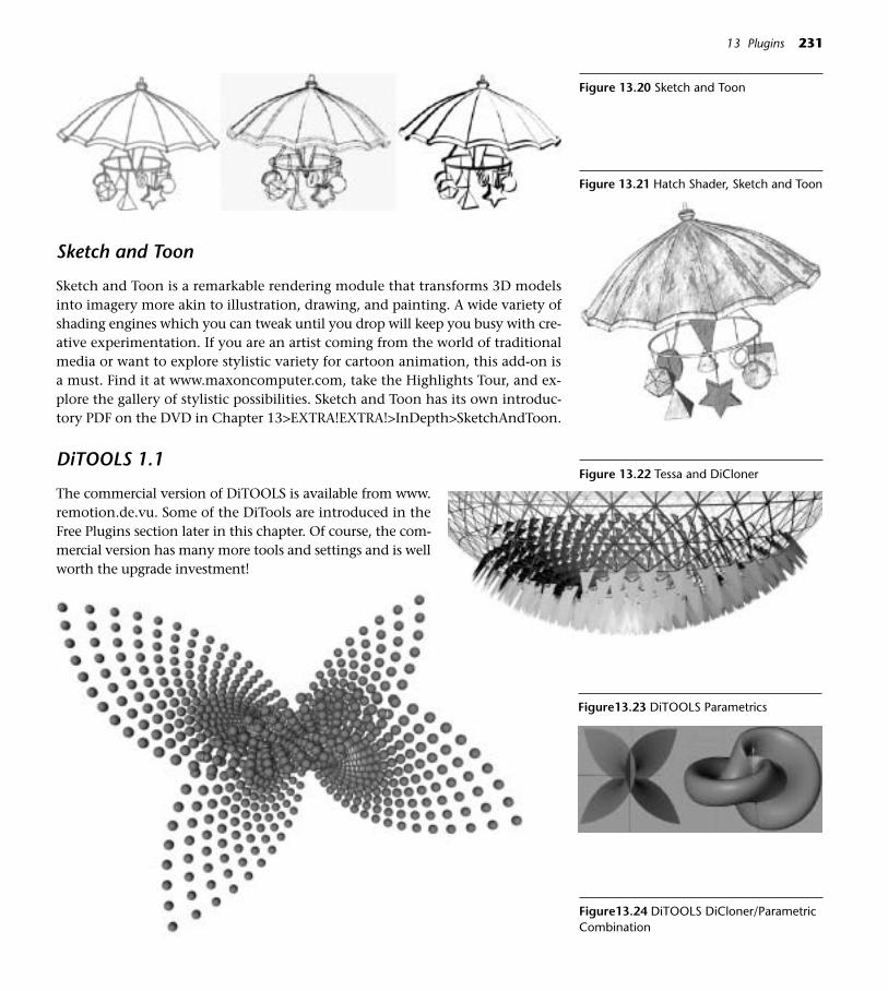
13 Plugins 231
Sketch and Toon
Sketch and Toon is a remarkable rendering module that transforms 3D modelsinto imagery more akin to illustration, drawing, and painting. A wide variety ofshading engines which you can tweak until you drop will keep you busy with cre-ative experimentation. If you are an artist coming from the world of traditionalmedia or want to explore stylistic variety for cartoon animation, this add-on isa must. Find it at www.maxoncomputer.com, take the Highlights Tour, and ex-plore the gallery of stylistic possibilities. Sketch and Toon has its own introduc-tory PDF on the DVD in Chapter 13>EXTRA!EXTRA!>InDepth>SketchAndToon.
DiTOOLS 1.1
The commercial version of DiTOOLS is available from www.remotion.de.vu. Some of the DiTools are introduced in theFree Plugins section later in this chapter. Of course, the com-mercial version has many more tools and settings and is wellworth the upgrade investment!
Figure 13.20 Sketch and Toon
Figure 13.21 Hatch Shader, Sketch and Toon
Figure 13.22 Tessa and DiCloner
Figure13.23 DiTOOLS Parametrics
Figure13.24 DiTOOLS DiCloner/ParametricCombination

SpeeDisplay, and Find and Replace
From Rui Batista, SpeeDisplay adds get-up-and-go to your editor display by lettingyou dynamically choose the level of detail. Find and Replace is a more sophisticatedtool for finding, replacing, and otherwise managing objects in complex scenes. Visitwww.ruimac.com for these and other great utility plugins.
Multiple Spline Attach and HELIX
Mikael Stern at www.xlentplugs.com is the creator of these long-time favorite plug-ins for C4D. Multiple Spline Attach provides a variety of useful tools for workingwith splines such as animatable chains and tank treads. HELIX creates coiled formsalong a spline. In addition to being indespensible for everyday tasks, these plug-ins are capable of oodles of creative fun far beyond their utilitarian appearance.
232 CINEMA 4D
Figure 13.25<<MSA
OnyxTREE
If you want believable trees, bushes, or foliage in your 3D world, OnyxTREE de-livers superb results. This standalone package is not a CINEMA 4D plugin butwill save models created in it as C4D files. The OnyxTREE 6 Suite has a quicklymastered interface and offers a deep level of customization. The materials withinOnyxTREE nicely support foliage that looks like the real thing, but if you wanteda glass tree you could also apply C4D materials once the model opens in CIN-EMA 4D. The OnyxTREE 6 Suite is available from www.onyxtree.com.
Figure 13.26 Helix
Figure 13.27 OnyxTREE

Ozone
Ozone is a powerful solution for creating animated atmospheric effects in CINEMA4D. The package includes two plugins, two atmospheric models, and tons of pre-sets for atmospheres and cloud forms. Ozone will let you create any approximationof nature or go out there on the horizon and invent never before seen environ-ments. Weather presets, fogs, haze, customized lighting, infinite cloud design, andextra goodies like rainbows and ice rings are all part of this highly productive anddefinitely “worth-it” tool available from www.e-onsoftware.com.
Xfrog
Xfrog 4 is a plugin for CINEMA 4D Release 8(PC or Mac) that enables the modeling and
animation of organic forms. Xfrog deftlyhandles trees, foliage, flowers, abstract
forms, and scientific visualizations.There are over 1,000 plant models
available in the XFR formatthat can be edited in C4D. Athirty-day demo is available
from www.xfrogdown-loads.com/greenweb
New/index.htm.
13 Plugins 233
Figure 13.28 Ozone
Figure 13.29 Xfrog Trees
Figure 13.30 Xfrog Plant Library
Figure 13.31 Xfrog Abstract Form
Add-the-Sea
This C4D plugin from www.motion-gimmick.de/a-t-s-e.htm cranks up C4D’smoving water capabilities quite a notch. You’ll also find the Pleasantville video-post plugin and others worth checking out.
Character Animation Helpers
Bonderland (c4dplugins.idea-graphics.de/BL/BL_docs.php) and Little Cup of MOC-CA (www.studio-fabian.de) are rigs that can be fit to your character design. Both in-clude readymade rigs (with all the tedious set-up work done for you) Bonderland(a commercial product) provides rigs for Bipeds, Quadrapeds and even Centipedes,along with a host of other awesome tools for rigging and animating characters inC4D. “Little Cup of MOCCA” is a plugin (with an accompanying rig which canbe fit to your Biped) and can be downloaded free.
Visual Selector (Paul Everett strikes again) simplifies the selection of elementsin a Character Animation rig. A character rig can be a sticky wicket, with manypieces and parts of varied functionality buried deep in hierarchies. This pluginmakes elements more apparent and their selection more intuitive.
MAXON’S Modules
Add-on Modules from MAXON are discussed in the appropriate chapters. Go towww.maxoncomputer.com to learn more about modules for CINEMA 4D. TheDynamics module handles physics simulation, allowing you to introduce natu-ral forces such as gravity, collision, and springs. The NET Render module is nec-essary for setting up distributed rendering over many machines in a lab. (This isespecially great for schools. Go home and leave the render farm chugging awayon a lab full of student renderings all night.)
Shareware and Freeware
DiTOOLS
DiTOOLS 0.892, available as a free download from www.remotion.de.vu is a suiteof tools that deform and generate ultracool models. These tools are especially ex-citing for the invention of original animated forms for motion graphics or ab-stract web imagery, but you can also use them for the creation of representationalmultiples like grass or spines. Many hours can be spent experimenting with theart potential of these tools. In a typical DiTOOLS maneuver the DiTOOLS objectwould have two children, a base object whose points would determine the posi-tions of cloned copies of the second child object. Furthermore, the behavior orparameters of the clones can be controlled with settings or affected by shaders ortextures. When the clones are being affected by an animated shader, the anima-tion possibilities start to get exciting. Here are just a few of the tools:
234 CINEMA 4D

• DiCloner. The DiCloner has two children. The first must have pointswhich will define the origin points of the clones. The child that representsthe object to be cloned can be anything. Think lights!
• DiSplinegen. The DiSplinegen generates multiple splines with the abilityto control the length of the splines with a texture. (It could be animated.)
• Parametric Generators. These provide settings for tweaking an awesomecollection of mathematically defined parametric objects, making it a quicktrip away from the same old models.
• DiFormer and DiShaper. The DiFormer and DiShaper deform a meshbased on a texture. Use these to make landscapes more bumpy.
• Tessa. This tool offers interesting interpretations on the surface structureof polygonal objects such as wire shaders.
Other DiTOOLS animate colors based on formulas, translate textures to ver-tex maps, and generate a material with numbers.
13 Plugins 235
Figure 13.32 DiTOOLS Examples
Hair Department
Hair Department makes terrific hair, fur, or grass, and the price is so right. Down-load it from www.bgs-group.de. Click English, then choose Service>Plugins. Youcan also download an English manual from this site (Figure 13.33).
Fizz
While Fizz has not been officially updated for versions 8.2 and higher, it seemsto work in most cases. Fizz is a set of add-on tools for particles that enables morecomplicated particle behavior, including the control of collisions, rolling, andfriction. It can be used to make particles bounce off of polygonal surfaces or offof other particles—very cool! Available from the Plugin Cafe at www.maxon-computer.com.
Stitch & Sew
One of several great plugins at Aquarius Graphic Wave (homepage2.nifty.com/aquawave) is Stitch & Sew. As the name implies, the plugin a useful tool for patch-ing together sections of mesh.
Figure 13.33 Mrs. Bobblehead

Time Frequency
Rui Mac’s Time Frequency plugin, provided for free at www.ruimac.com. is aneasy way to make twitchy color changes. This plugin works best in version 8.5,where the plugin is accessed at the bottom of the Shader (texture) list in eachchannel. (It isn’t in the top Plugins list.) Enter the starting and ending frames inthe first start and end boxes, select two colors in the next Start and End boxes,and enter a frequency to determine how fast the colors change. Experiment withthe curves to further design the nature of the “jumpiness” of the color.
236 CINEMA 4D
14A Jolt ofXpresso
237
Figure 14.1
C 4D users with programming skills have long been able to code minitoolsand bits of magic as add-ons to CINEMA 4D using C.O.F.F.E.E. This abilityto get under the hood is a huge advantage and greatly multiplies the power
of the basic application. The CINEMA community owes a great debt to the third-party programmers who share their talents in the Plugin Café (www.maxoncom-puter.com) and at other sites. Support them! For the rest of us, the more recentaddition of a visual interface called Xpresso lets nonprogrammers play too.
This chapter introduces the process of using the Xpresso Editor, and providespractice with some simple expressions. Realizing the full potential of Xpresso willbe an ongoing process. The best way to learn Xpresso is to analyze example ex-pressions (there are some on the DVD and links to many more) and read the com-ments. By all means, do read the manual and work through the tutorials forcreating Xpresso expressions. When the need for an expression arises in your ownwork, you should be able to customize just the right helper.
What Is Xpresso?
The Xpresso Editor is a graphical environment for building expressions. Expressionsare snippets of programming in which complex relationships between objects canbe created and controlled. Expressions often streamline or automate interactions,allowing you to bypass time-consuming and repetitive keyframing. In the XpressoEditor, visual building blocks called Nodes, representing objects or actions, are con-

nected with wires into working relationships. The visual nature of Xpresso makesit easy to understand the mechanics of the expression.
Xpresso: Basic Anatomy
An Xpresso expression is created by Command-clicking (right-clicking) on anobject in the Objects Manager and dragging to New Expression>Xpresso Expres-sion. In the Xpresso Editor that opens, you will create Nodes and establish re-lationships between them.
Step 1 Choose File>New and save the file as OrbitHandle in your Models folder(File>Save As).
Step 2 Choose a Cube Primitive and a Sphere Primitive. In the editor window,move the Sphere out to the side of the Cube. With the Sphere selected,press the C key. Choose the Object Axis tool and move the Sphere’s axisback to 0, 0, 0 inside the Cube.
238 CINEMA 4D
Step 3 Command-click (right-click) on the Cube and drag to NewExpression>Xpresso Expression. The Xpresso Editor window opens. If you want tobring it back up later for editing, just double-click the Xpresso Expres-sion tag.
Step 4 Drag the objects Cube and Sphere from the Objects Manager into theXpresso Editor window.
Figure 14.2 Primitives Positioned

Step 5 Practice editing the physical appearance of a Node. Move the mouse onthe red outlines around the selected Node to change the its size. Double-click the name to expand and minimize the window. To rename it, Com-mand-click (right-click) the name and drag down to Rename. Move themouse down on the white title bar to move the Node elsewhere in theEditor.
Step 6 Double-click the name Xgroup in the left column of the Xpresso Edi-tor and rename it Orbit Handle.
The Nodes you just made represents the Cube and Sphere in the expression.Nodes can also house information coming in to affect an object and going out fromthe object to affect something else. On the upper left of the box, the blue squarerepresents incoming information. The red square on the upper right is outgoing in-formation. An X-Group is a container for a related set of Nodes and Wires.
Step 7 Click on the Cube Node’s red square and drag to Coordinates>GlobalPosition>Global Position.Y so that the vertical position of the Cube willbe the outgoing information.
Information is passed from Node to Node via Ports and Wires. The red cir-cle you just created is a port that communicates the position of the Cube.
Step 8 Now click on the Sphere Node’s Blue input square and drag to Coor-dinates>Global Rotation>Global Rotation.H.
Step 9 Move the mouse down on the Square’s Global Position.Y port (the redcircle) and drag to the Sphere’s Global Rotation.H input port (the bluecircle). The wire is a connector between the ports. (If you wanted to re-move the wire you would click on it and drag it away.)
Step 10 Return to the Editor window and use the 3 key to tilt the view so youare looking down over the top of the objects. Use the green handle ofthe Move tool to drag the cube up and down.
You are using one type of information (cube position) to affect another type(sphere rotation). The vertical motion of the cube is driving the orbit of the sphere.
14 A jolt of Xpresso 239
Figure 14.3 The Xpresso Editor

240 CINEMA 4D
Figure 14.4 OrbitHandle
What’s in a Node?
Nodes, the basic building blocks of Xpresso expressions, fall into groups:
• The General group includes nodes that provide access to information or affect information. For example, an Object node represents a spe-cific object, material, or tag and can gather and output informationabout the object. Point or Polygon nodes provide access to specificunder-the-hood elements. A Constant node allows you to input a nu-meric value into the mix from the Attributes Manager. Other generalnodes like Random, Freeze, or Iterate affect the behavior of incominginformation.
• The Adaptor group converts values from one kind of data to another.The Bool group nodes generate true or false states, and the Calculategroup nodes apply math operations, manipulations, and constraints toinput values.
• The Logic group includes nodes that make comparisons or assess condi-tions which will determine further actions.

The Sticking Place
This simple expression will stick an object to a specific point on an animatedspline. (A similar expression could be used to stick an object to a particular poly-gon on a surface. See StickyTooth.c4d in the Chapter 14>EXTRA!EXTRA!>In-Depth folder on the DVD.)
Step 1 Open the file DieNotStuck.c4d from the Chapter 14>C4D Files folder onthe DVD. Look at the hierarchy and notice that the Die is a child of theString. Note that at Frame 0 the Die seems to be positioned just fine onthe String. Play the animation. When the Spline is PLA animated, theDie does not follow along.
Step 2 Choose File>Save As and save a working copy of the file as DieStuck.Now we will create an expression to stick the Die to a permanent spoton the string.
Step 3 Command-click (right-click) on the Die object in the Objects Manager.Drag to New Expression>Xpresso Expression. Drag the Path Spline andthe DIE into the Xpresso Editor window and enlarge their windows.
Step 4 In the Path Spline Node, drag on the red output square down to Ob-ject to create a port.
Step 5 In the Die Node, drag on the blue square down to Coordinates>GlobalPosition>GlobalPosition.
Step 6 We need a new Node that will allow us to define the position of a spe-cific point. Command-click (right-click) on the gray area of the XpressoEditor window and drag down to New Node>Xpresso>General>Point.
Step 7 Now we will create a new Node that will define which point the Dieshould stick to. Command-click (right-click) on the gray area of theXpresso Editor window and drag down to New Node>Xpresso>Gen-eral>Constant. In the Attributes Manager, you can input the numberof the point in the Value box.
How do you know the value of a point? Choose the Points tool and make surePath Spline is selected. Click the Structure tab next to the Objects tab at the top ofthe screen. In the Points column, click 0, 1, 2, and 3 and watch the spline in theeditor window to see how the points are identified.
Step 8 Select the Constant Node and enter 0 in the Value box (in the Attrib-utes Manager) so the Die will stick to the point on the right side of thestring.
Step 9 Connect the red Object output of the Path Spline Node to the blue Ob-ject input on the Point Node. Then connect the red Real (0) output ofthe Constant node to the blue Point Index input on the Point node.
14 A jolt of Xpresso 241
Figure 14.5 Structure Manager

242 CINEMA 4D
Those last two steps are informing the Point node that this specific point onthis spline is the point in question (in this case, the one you will be sticking theDie to).
Step 10 Now all that remains is to forward the position of the point that wasfed into the Point Node onward to the Die Node. Connect the red PointPosition port of the Point Node to the blue Global Position input onthe Die Node.
Play the animation and watch the Die stick to the sticking place!
● Springboard! Want a whole string of dice? Just Control-drag three copiesof the Die, then select the Constant Nodes and edit their values to be 1, 2,and 3. Make sure all the Die are children of the String object.
Stop Right There!
Did you ever want to stop a character’s foot from going through the floor with-out having to pay constant attention to the Y position? Here’s a simple, classicexpression to make your floor behave like a real floor instead of a virtual floor.
Step 1 Open the file Footstopper.c4d from the Chapter 14>C4D Files folder onthe DVD. Notice that the axis of the foot has been moved to the bot-tom of the foot.
Step 2 Command-click (right-click) on the FOOT object and drag to New Ex-pression>Xpresso Expression.
Step 3 Drag the FOOT object and the FLOORTILE object into the Xpresso Editor.
Step 4 Create a new Node by Command-clicking (right-clicking) in the XpressoEditor window and choose New Node>Xpresso>Calculate>Clamp.
Figure 14.6 DieXpresso Editor
Figure 14.7 Die Stuck
◆ Tip: The familiar navigation toolsat the top right of the XpressoEditor window can be used tomove around the Xpresso win-dow. The 1 and 2 keys work too.

Step 5 In both the FOOT and FLOORTILE nodes, click on the red output squaresand choose Coordinates>Global Position>Global Position.Y.
Step 6 Draw a Wire connector from the FLOORTILE Node to the Clamp Node’sMin input port.
Step 7 Make another connection from the FOOT output node to the ClampNode’s Max input port.
Step 8 Now connect another Wire from the FOOT output node to the ClampNode’s Value input port.
Step 9 Again, drag the name FOOT from the Objects Manager into the XpressoEditor window.
Click the blue input square and drag to Coordinates>Global Posi-tion>Global Position.Y.
Step 10 Draw a Wire from the Clamp output port to the Global Position.Y inputport on the new FOOT Node.
In the editor window, use the green Move handle to move the Footup and down.
14 A jolt of Xpresso 243
Figure 14.8 Footstopper Expression
Figure 14.9 Foot on Tile

What Else Can Be Done with Xpresso?
The possibilities are endless. Just to name a few, expressions can be designed thatoffset or randomize attributes and animation or that trigger events based on com-pared attributes or times. All kinds of math operations may be input to affect ob-jects and their motion. The best way to get a feel for the possibilities when you’rebeginning is to look through the descriptions of nodes in the CINEMA manual.We’ll be using more complex Xpresso expressions in Chapter 15 when we workwith Thinking Particles and PyroCluster.
On the DVD: See Chapter 14>EXTRA!EXTRA! for more examples of expressionsthat use other variables like time.
Connect: A Google search of “CINEMA 4D Expressions” should bring up examples.The Plugin Café at www.maxoncomputer.com also has an Expressions section.
244 CINEMA 4D

15Environment,Mood, andMagic
245
Figure 15.1
Agirl named Alice once said, “If I had a world of my own . . . .” In this chap-ter, we’ll build an interior structure with connected rooms nestled in anoutdoor environment. Throughout the chapter, the emphasis will be on
illusion. Much of what we create will be in the viewer’s mind, since we’ll use fa-çades, lighting, and other kinds of theatrical fakery to present an enchanted worldto the camera’s eye. It’s all a sham. Have you ever found yourself behind the scenesof a theme park in the glaring light of morning, wondering what happened to themagic of the night before? Who knew that the starlit outdoor cafe in old Mexicowas only paint and cracked plaster in a prefab metal building?
These projects will introduce skills for creating environments. This 3D worldwill function as a final project and be a place to showcase some of the things youmade as you worked through the book. The exact design or theme of your worldis up to you. Because it is open-ended, you could apply your original touches tothis personal space and use it as a demo piece. The example environment on theDVD, Eyefly, is a cross between a House of Mystery carnival ride and an art mu-seum. It’s a place where art, whimsy, and twisted funhouse collide and physicsdoesn’t live any more.
On the DVD: See sections of an example Eyefly project in Chapter 15>EXAM-PLES and MOVIES/STILLS.
In the EXTRA!EXTRA! folder be sure to check out References.pdf. In theGOODIES folder, there are materials you may want to use or edit for your envi-ronment.
The Interior Environment
Building the Basic Structure
We’ll start out with a simple tunnel structure. Later, if you want to remodel, infi-nite rooms can be added. Chapter 15>EXAMPLES>EYEFLY has examples of morecomplex versions.
Step 1 Working in the Top view, use the Bezier Spline tool to draw a path splinesimilar to the one in Figure 15.2.
Step 2 Working in the Front View, choose Spline>Rectangle Spline. Scale therectangle to be more in proportion with the spline, as in Figure 15.2.
Step 3 Choose NURBS>Sweep NURBS and drop the path spline in first, fol-lowed by the Rectangular cross section. (The cross-section profile couldbe another shape, such as the palladian shape in the example file.)
Step 4 Press the C key to make the Sweep NURBS editable.
Step 5 Choose Structure>Subdivide and enter a value of 2.
Step 6 Select and delete both caps inside the Sweep NURBS. Rename SweepNURBS as Basic Structure.
246 CINEMA 4D
Figure 15.2 Splines for Structure
Figure 15.3 The Basic Structure
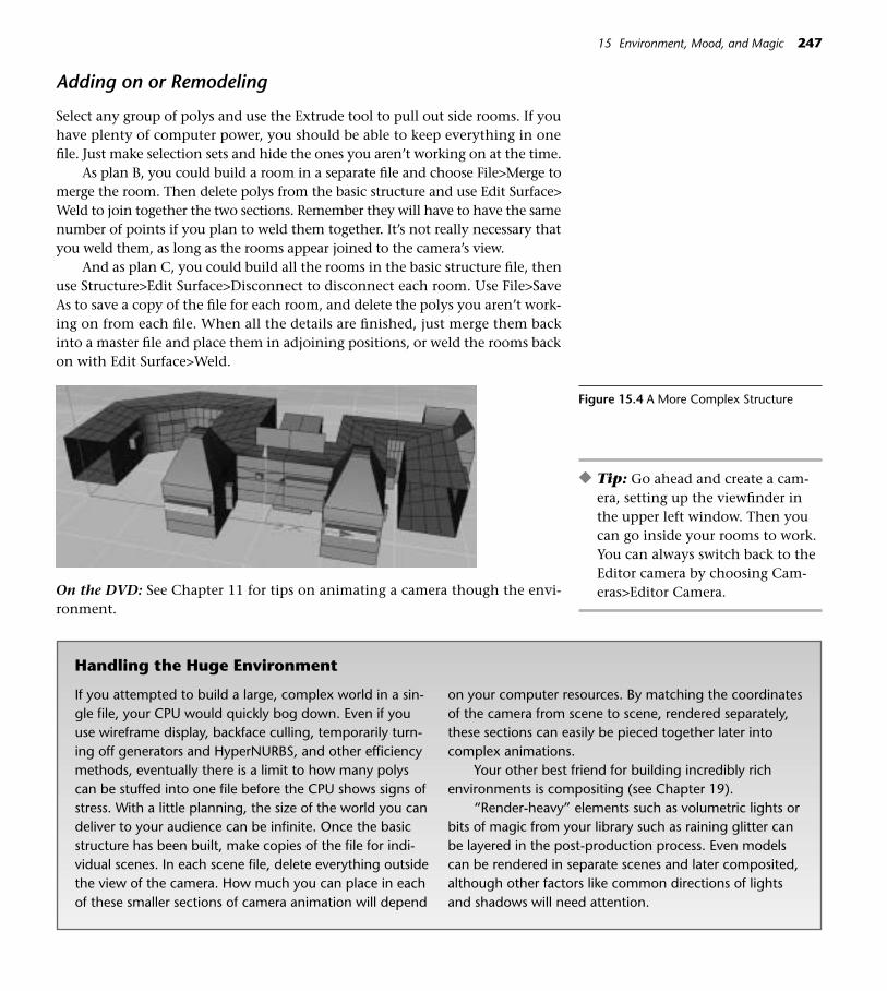
Adding on or Remodeling
Select any group of polys and use the Extrude tool to pull out side rooms. If youhave plenty of computer power, you should be able to keep everything in onefile. Just make selection sets and hide the ones you aren’t working on at the time.
As plan B, you could build a room in a separate file and choose File>Merge tomerge the room. Then delete polys from the basic structure and use Edit Surface>Weld to join together the two sections. Remember they will have to have the samenumber of points if you plan to weld them together. It’s not really necessary thatyou weld them, as long as the rooms appear joined to the camera’s view.
And as plan C, you could build all the rooms in the basic structure file, thenuse Structure>Edit Surface>Disconnect to disconnect each room. Use File>SaveAs to save a copy of the file for each room, and delete the polys you aren’t work-ing on from each file. When all the details are finished, just merge them backinto a master file and place them in adjoining positions, or weld the rooms backon with Edit Surface>Weld.
15 Environment, Mood, and Magic 247
On the DVD: See Chapter 11 for tips on animating a camera though the envi-ronment.
Figure 15.4 A More Complex Structure
◆ Tip: Go ahead and create a cam-era, setting up the viewfinder inthe upper left window. Then youcan go inside your rooms to work.You can always switch back to theEditor camera by choosing Cam-eras>Editor Camera.
Handling the Huge Environment
If you attempted to build a large, complex world in a sin-gle file, your CPU would quickly bog down. Even if youuse wireframe display, backface culling, temporarily turn-ing off generators and HyperNURBS, and other efficiencymethods, eventually there is a limit to how many polyscan be stuffed into one file before the CPU shows signs ofstress. With a little planning, the size of the world you candeliver to your audience can be infinite. Once the basicstructure has been built, make copies of the file for indi-vidual scenes. In each scene file, delete everything outsidethe view of the camera. How much you can place in eachof these smaller sections of camera animation will depend
on your computer resources. By matching the coordinatesof the camera from scene to scene, rendered separately,these sections can easily be pieced together later intocomplex animations.
Your other best friend for building incredibly richenvironments is compositing (see Chapter 19).
“Render-heavy” elements such as volumetric lights orbits of magic from your library such as raining glitter canbe layered in the post-production process. Even modelscan be rendered in separate scenes and later composited,although other factors like common directions of lightsand shadows will need attention.

Fun with Architectural Detail
As you design your 3D world, think about how you can use architectural detail tointroduce surprise and layered dimensions into the viewer’s experience of the space.Select smaller polys and extrude them back out of the structure to create nooks andcrannies. Some might have doors (that can be animated to creak open), some mightbe covered with glass (like an aquarium), still others may be mysteriously lit alcovesfor showcasing interesting models.
248 CINEMA 4D
After creating some details that sink back into the wall, try making some ele-ments that jut out of the wall into the space. The cloud in Figure 15.8 is flat fora cartoon look, but you could make a 3D, puffy one with a Metaball object. (Youhave already made the spline for this cloud in Chapter 2, so all you have to dois drop the cloud spline in an Extrude NURBS object.)
You can also add some elements that hang down, span the space, or add de-tail to edges and corners. The garland of flowers is a color and alpha map on aplane, intersected with a 3D pole. Check out the file in GOODIES>LIBRARIES>FLORAL TRIMS.
Relish lots of detail attention on your wall, ceiling, and floor surfaces. Play solidcolor against polished woodgrains, thickly painted white bricks against rusty beams.Add decorative elements like decoupaged pictures, graffitti, hooks with hanging ob-jects, wallpapers and wallpaper borders, numbers, letters, symbols, or esoterica. Add
Figure 15.5 Alcove Doors
Figure 15.6 Hinges: (L>R) Pointy Hinge,Mustardseed Hinge, Double Hinge , andClover Hinge,
Figure 15.7 Aquarium Insert

bump maps to emulate the textures of lumpy, flaking plaster or dripping thickpaint. Rich surfaces and layers of dirt and cracks, deep wall colors, molding, anddigital architectural “antiques” will enhance your space and make it believable. Re-search architectural details and interior design, and keep a sketchbook of traditionaland invented elements for use in your 3D spaces.
15 Environment, Mood, and Magic 249
Figure 15.8 Cloud
Figure 15.9 Hanging Things
Figure 15.10 Elements Invading the Space
Mixing Lights in an Interior Space
Nothing will add more depth, sense of place, and drama to your space than well-crafted lighting. Here are some general tips for orchestrating lighting in yourrooms. Study the example files for various set-ups of mixed lighting. Look at theplacement of the lights, the attributes for each light, and the materials placedon Light Fixtures.
• Compositionally speaking, it’s usually best to have one main direction ofshadow-casting light. This could be the Main (Key) light in the scene orlight coming in from a window. Add to that any necessary Fill light (withlittle or no shadow), and then place smaller lights that gently illuminatethe dark corners or function only as compositional interest (Radiationturned off).
• The collection of rooms in the final project will give you a chance to ex-periment with illumination. Use lighting purposefully to underscore thepersonality of each room. The spooky room might use a single, harshlight for a dramatic shadow, while a nostalgic room combine several lightsfor a soft, warm and comfy feeling.
• Use opposing color temperature with Main and Fill lights to create depthin the space, or assign colors to lights to attact attention or balance thecomposition. If a sky blue light is coming in the window, the shadows castwill be warm. A low, direct sun through a window will cast cool shadows.
• Create selection sets of lights for easy adjustment (see the Appendix).
• In this project with multiple rooms, think about shifting the light temper-ature from room to room as the kind of light fixtures change.
On the DVD: Don't miss Frederic Berti's scene file for “Something” in Chapter15>EXTRA!EXTRA!>InDepth. This scene from the C4D Masters Gallery (in theColor section) is a great example of complex lighting.
The World Outside: Skies, Backgrounds, and Cycloramas
Let’s make some daylight skies. The first sky will use the Sky object, a sphere in-finite in size and centered on 0, 0, 0. If you want to, make a skylight in your struc-ture to show off the sky.
Step 1 Choose Objects>Scene>Sky. Create a new material and click the colorchannel. Use a BhodiNUT Fusion shader in the Image box.
Step 2 Click the Edit button and place a BhodiNUT 3D Noise shader in theBlend Channel Image box. Check the Edit button for this shader andchoose Turbulance as the noise. Change the global Scale to 300 andthe X scale to 300.
250 CINEMA 4D

Step 3 Click OK and in the editor window for the Fusion shader, place a Bhod-iNut Gradient shader with colors ranging from deep blue to light blue.
Step 4 Change the mode in the left panel of the Fusion editing window to Over-lay. Place the new material on the Sky object, and click the Texture tag.There is an example of this sky in Goodies>Materials>Nature MaterialsLibrary if you want to check all those settings.
Step 5 Check Seamless in the Attributes, and adjust the X and Y tiling values toget the effect you want. The projection should be spherical or cubic. Up-ward camera angles will show a polar effect of the cloud shader, whichcan be fixed by choosing Shrink-wrapping projection for those camerashots. Save this generic sky to your Models folder if you want to keep itfor future use (File>Save As).8.5 Update The (BhodiNUT) Fusion Shader is now found by going toShader>Fusion. The former BhodiNUT 3D Noise is now called Noise inthe Shader list. Click the word Fusion in the elongated box to edit theBlend and Base channels. Use the navigation arrows at the top of theMaterial Editor to return to the Fusion pane where you can adjust theinteraction of the layers.
Now for a second way to make a sky:
In a new file, experiment with making a sky with floor objects. ChooseFile>Objects>Scene>Floor Object and make two copies of the floor. Sep-arate these floors on the Y so they float one over the other. Also infinitein size, the Floor object is a plane and can be used for anything thatstretches to infinity (such as skies or bodies of water). Note that in theeditor display it has a representative plane which does not look infinite,but it will be infinite when rendered.
Multiple floor objects can be layered with semitransparent cloudshaders and turbulance or noise materials animated in different speedsand directions. Make some materials that combine the colors found instormy skies (warm and cold greys, blues and unexpected colors likeochres and creamy yellows) with noise and turbulance shaders. Experi-ment with increasing the size of turbulance shaders for interesting cloudyskies. Animate subtle rotations of the floors, too.
Here’s the night version of the sky:
Step 1 Choose File>ObjectsScene>Sky Object. Create a new material andchoose the Starfield Shader.
Step 2 Create a few Omni lights with various small visibility distances andbarely there tints of warm and cool colors. Place them randomly in thesky. Animate some on and off visibility and visibility size to simulatetwinkling. For added realism you could animate an occasional shootingstar, some fireflies, or a blinking airplane light.
15 Environment, Mood, and Magic 251

252 CINEMA 4D
Figure 15.12 Night Sky
Figure 15.13 Sky Made with the OzonePlugin
Figure 15.11 Clouds on a Floor Object

Using Backgrounds and Foregrounds
Background and Foreground objects allow you to place images, colors, or tex-tures in front of or behind the models in a scene. Choose Objects>Scene>Back-ground and assign any material to it.
You can use a solid color like white if you are tired of the default black back-ground or a photographic image such as a city, landscape, or aerial view. You canalso place a movie sequence on the background. Choose a Foreground object foranything you want to appear in front of the rest of the scene, such as the dash-board of a car driving through the scene.
Backdrops, False Façades, and Cycloramas
As opposed to a background, a backdrop is an actual 3D object that you placeinto the scene. Usually a plane, it uses materials to fake the presence of objects
15 Environment, Mood, and Magic 253
Figure 15.14 DistantTrees and Alpha on aCyclorama
Figure 15.15 False Facades

farback in space. The Alpha channel can be used to drop out the plane aroundthe outline of objects. You can also construct backdrops like an actual theatreflat, (complete with canvas stretchers, rough wooden props and graffiti scrawledon the back) for an intriguing “fake, but real” element in your scene. A cyclo-rama, another crossover from the world of theater, is a plane or Bezier objectplaced outside a window or other viewport to provide bogus scenery only whereit’s needed. The material placed on the cyclorama could be a photograph, illus-tration, or again a movie.
The Outdoor Environment
We won’t build all of the great outdoors for our environment, just enough togive the illusion of an outside world.
Nature: Realistic or Stylized
Making a Landscape
Step 1 In a new file choose Primitive>Landscape Object. In the Attributes Man-ager, enter Sizes of X 10,000, Y 500, and Z 10,000. Alternately, use a verylarge plane, subdivide if necessary, and push the mesh polys into a landform you like.
Step 2 Press the C key to make the object editable, and choose Structure>Mag-net. In the Active tool tab, enter a Radius of 150. Nudge a small pondin the middle of the landscape. If the landscape needs to be smoother,drop the Landscape object into a HyperNURBS.
254 CINEMA 4D
Figure 15.16 Landscape and Pond
Step 3 Create your own Material, or choose a ground material from GOODIES>MATERIALS>Environment/Nature>NATURE MATERIALS.c4d. If youwanted a more cartoonlike material, you could use a BhodiNUT Cheenshader or hand-paint a stylized surface in BodyPaint. The free DiTOOLSPlugins available at www.remotion.de.vu have great tools for using ma-terials to displace surfaces into very organic landscapes.
Helper Apps for Natural Environments
While models straight from Bryce may have a canned, predictable look, you mayfind an occasional use for them in your digital toolbox. Nothing is more boringthan “already done for you” models, and using premade models will get you littlerespect in the 3D community. However, on occasion you might incorporate ele-ments created in these applications into your C4D worlds. You can find informa-tion on and support for Bryce at www.corel.com. Other applications for scenerygeneration are Vue d’Esprit and Vue 4 Professional, in which natural environmentswith advanced wind silumation can be animated. Check out their features at www.e-onsoftware.com. Terregen (www.terregen.com) is a free scenery generation ap-plication. Ozone creates awesome atmospheres (www.e-onsoftware.com), and Add-the-Sea (www.motion-gimmick.com) is a flowing water solution.
Connect: See Chapter 13 for information about environment plugins.
Water, Water Everywhere
The Pond in our project is still water, rippled by a light touch of wind.
Step 1 Choose Objects>Floor Object. (Note that you could use a plane insteadif you want to deform the surface more. The Formula Deformer or Struc-ture>Edit Surface>Crumple will deform a plane, but not a Floor object.For this still water, the shader will be enough to suggest water.)
Step 2 Create a new material and place the water shader in the color channel andbump channel. Layer semitransparent water or turbulance shaders onmultiple Floor objects (using the same process as the sky made with mul-tiple Floors earlier). Don’t forget that the water and turbulence shaderscan be animated. Open the water material in GOODIES>MATERIALS>En-vironment/Nature>NATURE MATERIALS.c4d and study the settings.
Step 3 Save the Landscape and Pond to be merged later with the Indoor struc-ture (File>Save or Cmd+S/Ctrl+S).
You can create dripping or slowly rolling puddles of water with a Metaballobject:
Step 1 Choose a Metaball object from the Array palette. In the AttributesManager, try a hull value of 40 percent, and 5 Subdivisons for Editorand Render.
15 Environment, Mood, and Magic 255

Step 2 Choose Objects>Spline Object. Make sure the Move tool and the Pointstool are selected, and Control-click some points in a long line across thescreen.
Step 3 Enable PLA Animation, and animate the points to move in the generaldirection you want the puddle to move.
Step 4 Make the Spline Object a child of the Metaball object.
Step 5 To make the puddle appear flatter, sink the metaball down under thefloor or surface it’s sitting on.
● Springboard! Take the Metaball object a step farther and make a foun-tain. Open the file Fountain.c4d in the Chapter 15>EXAMPLES>Fountainfolder. Study the set-up of the Particle Emitter inside the Metaball object.Then check out the settings in the Attributes Manager for Particle, Emitter,and the Metaball itself. You can copy the material from this file for makingyour own fountain.
Connect: Want to make an underwater scene? The Advanced Render PDF in theChapter 12>EXTRA!EXTRA!>InDepth on the DVD shows how to use Caustics tocreate the undersea illusion. If you think the next step is the making of surgingocean waves splashing on rocks, hold that thought—that is one thing that won’thappen easily in C4D, and not without special plugins. See Chapter 13.
Trees
A decent, distant realistic tree can be made with this manual method. The secretto this manual method is the alpha material. Navigate to Chapter 15>EXAM-PLES>Tree.
The groups of leaves are placed on single polygons that were duplicated (20instances) and then randomized in position, scale, and rotation. The resultingNull Object can be copied several times for more thickness, and a copy can bescaled down and placed in the center of the tree for more density.
From the Chapter 15>EXAMPLES>Tree folder, open the Tex folder and lookat the materials for the Color and Alpha channels.
For a distant tree, a cylinder made editable and bent in a few places usingthe Magnet tool will do fine for the trunk. The limbs are multiples of Stick 1 inGOODIES>LIBRARIES>Sticks and Weeds>Stick Library. Once the wood materialis placed on the truck and limbs, it works visually as a unit.
After you place your tree in a scene, you may need to rotate some of the “leafy”polys for more randomization, better angles, or more specific placement. Just clickon the offending polys in the editor window and use the Move and Rotate tools toadjust them, or select Null groups in the Objects Manager to rotate so they look bet-ter from the camera angle. If it’s a close-in tree shot you need, a more specific image
256 CINEMA 4D
Figure 15.17 Fountain
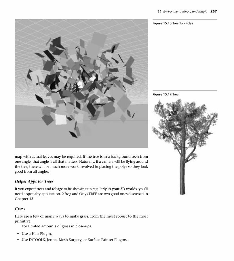
map with actual leaves may be required. If the tree is in a background seen fromone angle, that angle is all that matters. Naturally, if a camera will be flying aroundthe tree, there will be much more work involved in placing the polys so they lookgood from all angles.
Helper Apps for Trees
If you expect trees and foliage to be showing up regularly in your 3D worlds, you’llneed a specialty application. Xfrog and OnyxTREE are two good ones discussed inChapter 13.
Grass
Here are a few of many ways to make grass, from the most robust to the mostprimitive.
For limited amounts of grass in close-ups:
• Use a Hair Plugin.
• Use DiTOOLS, Jenna, Mesh Surgery, or Surface Painter Plugins.
15 Environment, Mood, and Magic 257
Figure 15.18 Tree Top Polys
Figure 15.19 Tree

• Use Edit Surface>Matrix Extrude.
• Create a single grass blade model, Duplicate Instances, and then randomize.
For large, distant grassy surfaces, rely on materials placed on the surface tofake the look of grass.
How’s the Weather?
To make some simple rain or snow, we’ll use the Particle Emitter. In the next sec-tion, we’ll move up a notch and use the Thinking Particles module to create Par-ticle Systems with much more control.
Step 1 Make a single weather particle model. Depending on the style of youranimation, it could be a long and very skinny cube for more realisticrain, a sphere for realistic snow, or a teardrop or snowflake for morecartoon-like precipitation. Whatever it is, make it small. A 2m spherewould be fine.
Step 2 Experiment with your own materials or use the ones in Goodies>Ma-terials>Weather. Place some kind of turbulence into the alpha of thematerial to keep the model from looking too hard-edged.
258 CINEMA 4D
Step 3 Choose Objects>Particles>Emitter to create an Emitter object. Rotatethe emitter so that its Z axis is pointing downward and move it to thetop of the screen.
Step 4 Make your weather particle a child of the Emitter object. Select theEmitter.
Step 5 In the Attributes Manager, click the Emitter tab. For a weather systemyou’ll need the X value to stretch all the way across the screen. It canbe as deep or as shallow on the Y as you need it to be for the level ofrealism desired.
Figure 15.20 Weather Models

Step 6 Try changing the Horizontal and Vertical Angle values to create nar-rower and wider sprays. A value of 360 on both would will spew par-ticles out in all directions. For our weather system, we don’t really needany angle settings as we want the precipitation to fall straight down.
Step 7 Click the Particle tab. Enter the number of particles you want in theeditor and the render. Enter a value for scale variation if you want theparticles to vary in size. If the check box for show objects is unchecked,a representive tic will appear in the editor. If you want to see the par-ticles, check the box. Having done that, you can now see the results ofyour variation settings better. Just be sure to scrub all the way to thebeginning of the animation for an accurate preview.
Step 8 To make your weather a little more blustery, choose Objects>Particles>Wind and place the new object on the same hierarchical level with theEmitter. Scale and position the modifier so that it encloses the particlesyou want to affect. Try some of the other tools in the particle menu. Youcan stack up multiple modifiers for some interesting custom effects.
A cool thing about emitters is that you can put more than one object in asa particle. In other words, you could put all the letters of the alphabet in the emit-ter at one time and rain alphabet soup.
15 Environment, Mood, and Magic 259
Figure 15.21 Cartoon Snowflakes in anEmitter
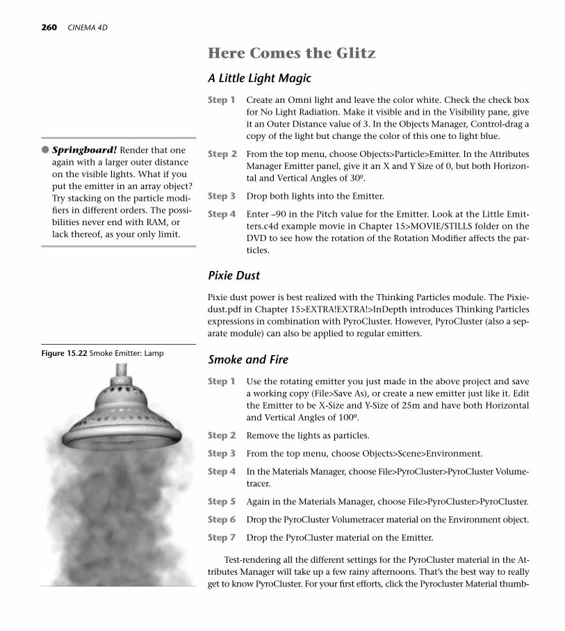
Here Comes the Glitz
A Little Light Magic
Step 1 Create an Omni light and leave the color white. Check the check boxfor No Light Radiation. Make it visible and in the Visibility pane, giveit an Outer Distance value of 3. In the Objects Manager, Control-drag acopy of the light but change the color of this one to light blue.
Step 2 From the top menu, choose Objects>Particle>Emitter. In the AttributesManager Emitter panel, give it an X and Y Size of 0, but both Horizon-tal and Vertical Angles of 30º.
Step 3 Drop both lights into the Emitter.
Step 4 Enter –90 in the Pitch value for the Emitter. Look at the Little Emit-ters.c4d example movie in Chapter 15>MOVIE/STILLS folder on theDVD to see how the rotation of the Rotation Modifier affects the par-ticles.
Pixie Dust
Pixie dust power is best realized with the Thinking Particles module. The Pixie-dust.pdf in Chapter 15>EXTRA!EXTRA!>InDepth introduces Thinking Particlesexpressions in combination with PyroCluster. However, PyroCluster (also a sep-arate module) can also be applied to regular emitters.
Smoke and Fire
Step 1 Use the rotating emitter you just made in the above project and savea working copy (File>Save As), or create a new emitter just like it. Editthe Emitter to be X-Size and Y-Size of 25m and have both Horizontaland Vertical Angles of 100º.
Step 2 Remove the lights as particles.
Step 3 From the top menu, choose Objects>Scene>Environment.
Step 4 In the Materials Manager, choose File>PyroCluster>PyroCluster Volume-tracer.
Step 5 Again in the Materials Manager, choose File>PyroCluster>PyroCluster.
Step 6 Drop the PyroCluster Volumetracer material on the Environment object.
Step 7 Drop the PyroCluster material on the Emitter.
Test-rendering all the different settings for the PyroCluster material in the At-tributes Manager will take up a few rainy afternoons. That’s the best way to reallyget to know PyroCluster. For your first efforts, click the Pyrocluster Material thumb-
260 CINEMA 4D
● Springboard! Render that oneagain with a larger outer distanceon the visible lights. What if youput the emitter in an array object?Try stacking on the particle modi-fiers in different orders. The possi-bilities never end with RAM, orlack thereof, as your only limit.
Figure 15.22 Smoke Emitter: Lamp

nail and edit the settings in the Attributes Manager, using the Preview button to seethe effects. The Noise types on the Fractal panel will give you an idea of the widevariety of things you can do with PyroCluster. In the Applications>MAXON>CIN-EMA R8>Features>PyroCluster folder, there are plenty of starter examples.
Connect: As you begin to craft more complex worlds, connect to these skills fromother chapters. They are major players for adding magic to your environments.
• Strings of Lights and other twinkling lighting. Use those F-Curves to ran-domize light visibility for twinkling effects (Chapter 6).
• “Painted” atmospheres or blinking puffs of colored visible lights (Chapter 6).
• Highlights and Glow (Chapter 12).
• Hand-painting decorative elements (Chapter 16).
• Glitter Materials, (Chapter 5),
On the DVD: See the Chapter 15>MOVIE/STILLS folder for examples of sparkle,magical lighting, decorative painting, and fun with architectural details.
The Importance of Music and Sound
The process for placing sound into CINEMA 4D for preview is discussed in Chap-ter 7, Animation ABCs. So, just a word about sound. Appropriate music andtimely sound effects can make or break your project. And don’t neglect the layers
15 Environment, Mood, and Magic 261
Figure 15.23 Smoke Emitter: Spinnercraft

262 CINEMA 4D
of secondary ambient noise that can add realism to your world. It would be wellworth your while to master some kind of sound mixing application if you planon hanging around the world of 3D.
● Springboard! Now that you have the basic idea of how to create thestructure of a world, you are ready to fill it with objects, textures, colors,and sounds. It’s a good time to go back and review all the things you’velearned in other chapters and to think about how you can incorporatethose elements into a finished project.
On the DVD: If you have the Thinking Particles module and are ready to starttoward poweruser status, be sure to work through the Pixiedust.pdf in Chapter15>EXTRA!EXTRA!>InDepth.
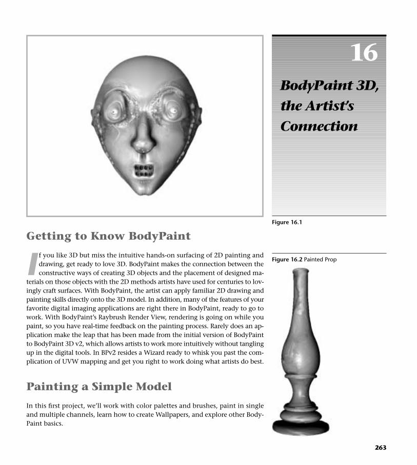
16BodyPaint 3D,the Artist’sConnection
263
Figure 16.1
Getting to Know BodyPaint
I f you like 3D but miss the intuitive hands-on surfacing of 2D painting anddrawing, get ready to love 3D. BodyPaint makes the connection between theconstructive ways of creating 3D objects and the placement of designed ma-
terials on those objects with the 2D methods artists have used for centuries to lov-ingly craft surfaces. With BodyPaint, the artist can apply familiar 2D drawing andpainting skills directly onto the 3D model. In addition, many of the features of yourfavorite digital imaging applications are right there in BodyPaint, ready to go towork. With BodyPaint’s Raybrush Render View, rendering is going on while youpaint, so you have real-time feedback on the painting process. Rarely does an ap-plication make the leap that has been made from the initial version of BodyPaintto BodyPaint 3D v2, which allows artists to work more intuitively without tanglingup in the digital tools. In BPv2 resides a Wizard ready to whisk you past the com-plication of UVW mapping and get you right to work doing what artists do best.
Painting a Simple Model
In this first project, we’ll work with color palettes and brushes, paint in singleand multiple channels, learn how to create Wallpapers, and explore other Body-Paint basics.
Figure 16.2 Painted Prop

Setting up with the BodyPaint Set-up Wizard
Step 1 Open the file PaintedProp.c4d from the Chapter 16>C4D Files folderon the DVD. Save a working copy to your Models folder (File>Save As).
Step 2 Select the Lathe Object in the Objects Manager, and turn off all otherobjects in the scene except the Light. Press the C key to make the ob-ject editable. (It is necessary to make parametrics editable before UVscan be recalulated.)
Step 3 Select the BP 3D Paint Layout from the Layout Icon (the top icon onthe Left Palette).
Step 4 Click on the Paint Set-up Wizard. On the first page of the Wizard (Step1), make sure only the Lathe Object has a green check mark. Click onthe names of the other objects so the green check marks turn to red.Click Next.
Step 5 On the Step 2 page, accept the default choices by clicking the Next but-ton. (If you had a file with separate objects and wanted to create sepa-rate textures for each rather than painting across all the objects withone texture, you would uncheck Single Material Mode.)
Step 6 On the Step 3 page, check the boxes for Color and Bump. Click the boxnext to color and edit the color to be a pale gold-orange. Leave the Bumpcolor gray and click the Finish button. Wait for the Wizard to make itscalculations (Set-up Wizard End will be the last line in the list) and clickthe Close button. You’re ready to paint.
The Basic Tools
Step 1 Click the Colors tab in the upper right of the screen, then click on theChannels panel. You’ll see Co for Color and B for Bump, correspondingto the two channels you created in the Wizard. To the left of those, thereis a box with a pencil and a green check mark or red cross mark.
If the green check is showing, multichannel mode is enabled and you canpaint in both channels (or more if you originally set them up in the Wizard) si-multaneously. If the red cross mark is showing, you will only be painting in theactive channel with pencil showing and a red line around it. You can click thered line to enable either for painting, but only one will be active at a time untilMultichannel mode is enabled again.
Take a moment to stop and absorb this one, as it is a critical concept of howBodyPaint works. Even after you understand it, you’ll still have to concentrate tobe sure you are assigning a color to the channel you intend to paint in. Notice thateither Color or Bump will have a red line around it at any given time. The chan-nel with the red line is the one for which you are choosing a color and/or wall-paper. The color chosen for the color channel will paint that color or wallpaper.
264 CINEMA 4D
Figure 16.3 Layout Icon
Figure 16.4 Paint Setup WizardIcon
Figure 16.5 Wizard Page One
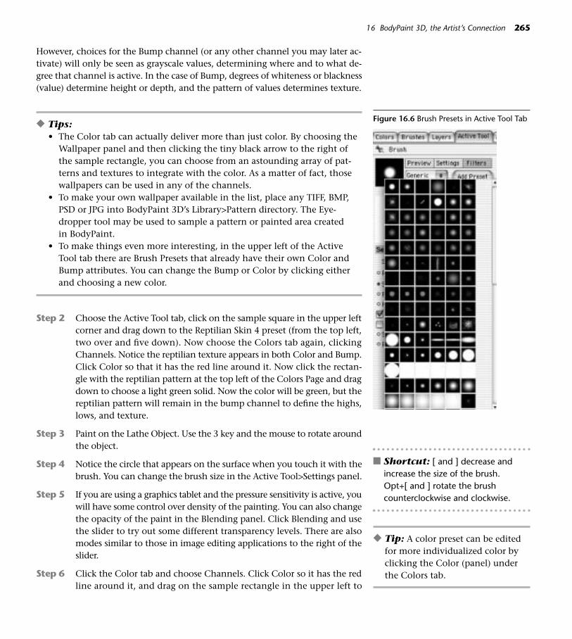
However, choices for the Bump channel (or any other channel you may later ac-tivate) will only be seen as grayscale values, determining where and to what de-gree that channel is active. In the case of Bump, degrees of whiteness or blackness(value) determine height or depth, and the pattern of values determines texture.
◆ Tips:• The Color tab can actually deliver more than just color. By choosing the
Wallpaper panel and then clicking the tiny black arrow to the right ofthe sample rectangle, you can choose from an astounding array of pat-terns and textures to integrate with the color. As a matter of fact, thosewallpapers can be used in any of the channels.
• To make your own wallpaper available in the list, place any TIFF, BMP,PSD or JPG into BodyPaint 3D’s Library>Pattern directory. The Eye-dropper tool may be used to sample a pattern or painted area createdin BodyPaint.
• To make things even more interesting, in the upper left of the ActiveTool tab there are Brush Presets that already have their own Color andBump attributes. You can change the Bump or Color by clicking eitherand choosing a new color.
Step 2 Choose the Active Tool tab, click on the sample square in the upper leftcorner and drag down to the Reptilian Skin 4 preset (from the top left,two over and five down). Now choose the Colors tab again, clickingChannels. Notice the reptilian texture appears in both Color and Bump.Click Color so that it has the red line around it. Now click the rectan-gle with the reptilian pattern at the top left of the Colors Page and dragdown to choose a light green solid. Now the color will be green, but thereptilian pattern will remain in the bump channel to define the highs,lows, and texture.
Step 3 Paint on the Lathe Object. Use the 3 key and the mouse to rotate aroundthe object.
Step 4 Notice the circle that appears on the surface when you touch it with thebrush. You can change the brush size in the Active Tool>Settings panel.
Step 5 If you are using a graphics tablet and the pressure sensitivity is active, youwill have some control over density of the painting. You can also changethe opacity of the paint in the Blending panel. Click Blending and usethe slider to try out some different transparency levels. There are alsomodes similar to those in image editing applications to the right of theslider.
Step 6 Click the Color tab and choose Channels. Click Color so it has the redline around it, and drag on the sample rectangle in the upper left to
16 BodyPaint 3D, the Artist’s Connection 265
Figure 16.6 Brush Presets in Active Tool Tab
■ Shortcut: [ and ] decrease andincrease the size of the brush. Opt+[ and ] rotate the brushcounterclockwise and clockwise.
◆ Tip: A color preset can be editedfor more individualized color byclicking the Color (panel) underthe Colors tab.

choose a bright orange solid color. Click the Bump channel so it now issurrounded by the red line. Now open the Wallpaper panel, and dragdown on the tiny black arrow under the word Wallpaper to Dirtg02b.jpg.Paint with this new hybrid material on the Lathe Object, experimentingwith different Blending modes.
Step 7 The result of your painting may be a little fuzzy and hard to see. Justturn on Raybrush Render View, and the painting will be rendered inreal-time for a clear picture of your artistry.
266 CINEMA 4D
Figure 16.7 Wallpapers
Step 8 Want to work on your texture in a flat 2D state? Click the Texture tabon the upper left of the View. Click the View tab to return to paintingon the model.
Step 9 Experiment with editing brushes in the Active Tool tab. Click Add Pre-set and enter a name for any brush design you want to keep.
Step 10 Now for some serious art fun! Choose Window>Brush Presets. Drag thepushpin from that window to the pushpin in the upper left of the Col-ors window to add it as a tab with the other important tabs. Click theBrushes tab. First, open some of those folders and check out how manybrush presets you have (that’s not even counting the ones you canmake yourself). You can close your mouth now, and open the Oil folder.Choose Oil Round Wide.
Step 11 Paint on the Lathe Object. Notice how the brush is picking up the ex-isting color, blending it into the new color like real oils.
■ Shortcut: Want to use the paint already on the surface as a palette? Holddown the Ctrl key and use the Eyedropper tool to sample any area, then paintwith the sampled color.
Step 12 To keep a floating color palette more handy, choose Window>Color Pre-sets. If you want to edit a preset and keep the new version, double-clickthe preset and edit it in the Color panel, then choose File>Add SingleColor Preset from the Color Panel menu and give the new preset aname. If you want to replace an existing preset, choose File>Overwrite
Figure 16.8 Ray-brush Render View

Preset. Check the Colors>View menu for ways you can set up the palette.Sometimes, it is easier to identify a preset by name so viewing by list ishelpful.
Finish painting the Lathe Object with abstractions of color and texture. Ex-periment with various combinations of color, blending, wallpapers, and brushstyles for infinite possibilities. Do your own thing. There are examples on theDVD in the Chapter 16>EXTRA!EXTRA!>InDepth folder if you need inspiration.
◆ Tips:• Remember to use the 3 key and mouse to paint all the way around the
object. On the other hand, if you are creating the object for a still seenfrom the front view only, no one needs to know you didn’t waste yourtime painting a back that will never be seen.
• Ready to get rid of that Reptilian texture now? Any texture that waspainted in the Bump channel can be erased (actually, flattened back tothe original surface) by painting over the texture with a medium grayin the Bump channel.
• To paint a stroke with optimum lift up off the surface, choose white forthe Bump color. For a stroke that digs down deep into the surface, thebump color should be black. A black and white texture in the BumpChannel will make the most obvious 3D textural surface.
• So many brush presets, colors, and wallpapers—here are some favoritesto get you started: Watercolor Rough Brush Preset, Smear>Tri SmearBrush Preset, Brush Settings>Spacing and Jitter.
16 BodyPaint 3D, the Artist’s Connection 267
Figure 16.9 Floating Color Palette
Figure 16.10 Painted Prop
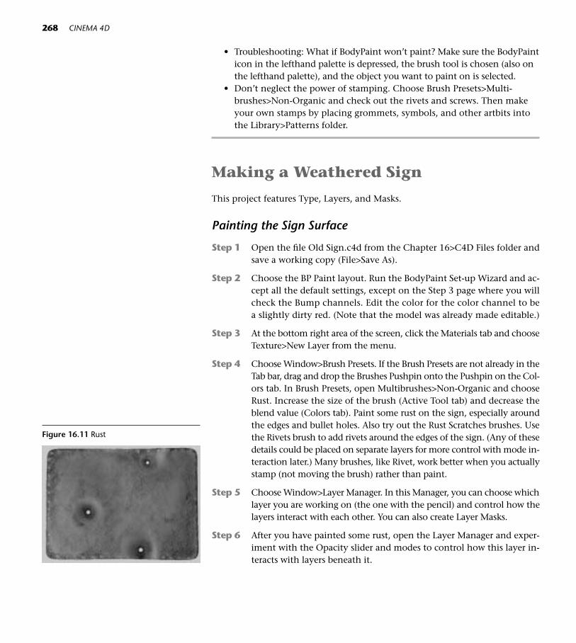
• Troubleshooting: What if BodyPaint won’t paint? Make sure the BodyPainticon in the lefthand palette is depressed, the brush tool is chosen (also onthe lefthand palette), and the object you want to paint on is selected.
• Don’t neglect the power of stamping. Choose Brush Presets>Multi-brushes>Non-Organic and check out the rivets and screws. Then makeyour own stamps by placing grommets, symbols, and other artbits intothe Library>Patterns folder.
Making a Weathered Sign
This project features Type, Layers, and Masks.
Painting the Sign Surface
Step 1 Open the file Old Sign.c4d from the Chapter 16>C4D Files folder andsave a working copy (File>Save As).
Step 2 Choose the BP Paint layout. Run the BodyPaint Set-up Wizard and ac-cept all the default settings, except on the Step 3 page where you willcheck the Bump channels. Edit the color for the color channel to bea slightly dirty red. (Note that the model was already made editable.)
Step 3 At the bottom right area of the screen, click the Materials tab and chooseTexture>New Layer from the menu.
Step 4 Choose Window>Brush Presets. If the Brush Presets are not already in theTab bar, drag and drop the Brushes Pushpin onto the Pushpin on the Col-ors tab. In Brush Presets, open Multibrushes>Non-Organic and chooseRust. Increase the size of the brush (Active Tool tab) and decrease theblend value (Colors tab). Paint some rust on the sign, especially aroundthe edges and bullet holes. Also try out the Rust Scratches brushes. Usethe Rivets brush to add rivets around the edges of the sign. (Any of thesedetails could be placed on separate layers for more control with mode in-teraction later.) Many brushes, like Rivet, work better when you actuallystamp (not moving the brush) rather than paint.
Step 5 Choose Window>Layer Manager. In this Manager, you can choose whichlayer you are working on (the one with the pencil) and control how thelayers interact with each other. You can also create Layer Masks.
Step 6 After you have painted some rust, open the Layer Manager and exper-iment with the Opacity slider and modes to control how this layer in-teracts with layers beneath it.
268 CINEMA 4D
Figure 16.11 Rust

Creating a Mask
Step 1 In the Layers Manager, select the red background layer. Undock the Lay-ers Manager for easy access to it and the Colors tab at the same time.
Step 2 From the menu at the top of the Layers Manager, choose Functions>Du-plicate Layer. From the same menu choose Functions>Add Layer Mask.Notice the Layer Mask Thumbnail in the Layer Manager. If it has a redline around it (click on it if it doesn’t) anything you paint or draw willappear on the Mask. From the Colors tab, choose black as the color. Fromthe left palette, choose the Paintbucket (Fill Bitmap) tool and click on theimage to fill the Mask shape with black. Then change the color to whiteby choosing it from the Colors tab.
Step 3 From the Left Palette, choose the Draw Polygon Shape tool.
Step 4 Click the Active Tool tab on the upper right, and drag down to Star in theShape pulldown menu. Click Edit and give the Star five points. Click inthe center of the sign and drag a Star shape that works well with the bul-let holes. Now in the Layers Manager, click back on the image thumbnailto the left of the mask thumbnail. Since you chose the Fill Bitmap tool(the Paintbucket) before, you will have to click back on the Brush tool toreturn to painting. Anything you paint on the image now will be blockedby the mask.
Step 5 Choose Brush Presets>Multibrushes>Dosch Texture Brushes>Stone 3.Paint inside the Star.
Step 6 After you paint the Star, return to the Layer Manager and use the Opac-ity slider and the modes pull-down menu to make the star look morelike faded paint.
Making the Sign Letters
Step 1 Click the Colors tab and activate the Color channel. In the Layers Man-ager, choose Functions>New Layer. Choose a color and brush style.
Step 2 From the Left Palette, choose the Draw Text tool. In the Active Tool tab,type A R T in the text box. Click the Select button to choose a font. Entera size of 200 and choose Align>Center. Enter a Feather value of 2.
Step 3 Click the I-beam to place the text on the surface. If you miss, just pressCmd+Z (Ctrl+Z) and try again.
Step 4 Create another New Layer and repeat the text creation above, exceptenter a size of 125 for the word “AHEAD.”
Step 5 Select each layer and experiment with the opacity slider and modes.
16 BodyPaint 3D, the Artist’s Connection 269
Figure 16.12 Fill BitmapTool
Figure 16.13 Draw Polygon Shape

Step 6 The type on each layer needs to be dirtied up a bit. Return to the Brushicon on the left palette. Choose a Charcoal Chunky from the Brush Pre-sets, and in the Active Tool tab click the Filters panel. Play back and forthon the letters with the Dodge and Burn filters. You may want to add sometouches of migrant color to the letters also.
270 CINEMA 4D
Figure 16.14 Draw Text Tool
Figure 16.15 Old Sign
Painting a Head with BodyPaint
To be a spooky Wizard, Mr. Bobblehead needs some surface interest. In this proj-ect, we’ll use the color and bump channels to create dry scaly skin, wrinkles, veins,scars, warts, and other lovely details.
Preparing the Head for Painting
Be sure to save frequently and say yes when BodyPaint asks if you want to savethe textures, which must be saved in a separate file and kept with the .c4d file. Ifyou use Save Project, the BodyPaint files will be in the right place.
Step 1 Open the file Mr.Bobblehead.c4d from the Chapter 16>C4D Files folderon the DVD. Save a working copy to your Models folder (File>Save As).Choose the BP 3D Paint Layout.

Step 2 Click the Paint Set-up Wizard. On the Step 1 page, check Deselect Alland then click the red checkmark next to the Cube so it turns green.On the Step 3 page, check Color and Bump. Edit the Color channel tobe a sickly pale skin base color. Click Finish and Close.
16 BodyPaint 3D, the Artist’s Connection 271
Figure 16.16 Wizard Step 1
Figure 16.17 Wizard Step 3
Projection Painting
Take advantage of BodyPaint’s Projection Painting mode. This lays the paintonto an invisible plane floating parallel to the screen and then drops it ontothe model. The advantage of this mode is that brush strokes are more trueand undistorted. If you change views or click the Apply Projection Painticon, the paint will be applied to the surface. To continue painting on othersides of the model, rotate the view and projection paint in that view. If youclick the Discard Projection Paint,the painting will not be applied. To activate Projection Paint, click theEnable Projection Paint icon.
Figure 16.18 L>R,3DPaint Enable, Pro-jection Paint Enable,Apply and Discard
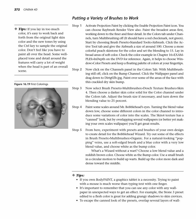
Putting a Variety of Brushes to Work
Step 1 Activate Projection Paint by clicking the Enable Projection Paint icon. Youcan choose Raybrush Render View also. Paint the broadest areas first,working down to the finer and finer detail. In the Colors tab under Chan-nels, turn Multibrushing off (It should have a red checkmark, not green).Start by choosing Brush Presets>Standard Tools>Airbrush. Click the Ac-tive Tool tab and give the Airbrush a size of around 100. Choose a morecolorful peach skintone for the color and set the blending to 15. Lay inbroad areas of soft color. Check the color example in Chapter 16>EXAM-PLES>InDepth on the DVD for reference. Again, it helps to choose Win-dow>Color Presets and keep a floating palette of colors at your fingertips.
Step 2 Now click on the Channels panel in the Colors Tab. With Multibrush-ing still off, click on the Bump Channel. Click the Wallpaper panel anddrag down to Dirtg02b.jpg. Paint over some of the areas of the face withthis crackled dry skin bump.
Step 3 Now select Brush Presets>Multibrushes>Dosch Texture Brushes>Skin4. Then choose a darker skin color solid for the Color channel underthe Colors tab. Adjust the brush size if necessary, and turn down theblending value to 25 percent.
Step 4 Paint some scales around Mr. Bobblehead’s eyes. Turning the blend valuedown low, choose some different colors in the color channel to intro-duce some variations of color into the scales. The Skin4 texture has a“canned” look, but by overlapping several wallpapers (or better yet mak-ing your own scales wallpaper) you’ll get great results.
Step 5 From here, experiment with presets and brushes of your own designto create detail for the Bobblehead Wizard. Try out some of the effectsin Brush Presets>Multibrushes>Organic. For a natural-looking “pop-ping” veins, use a soft-edged brush and a blue color with a very lowblend value, and choose white as the bump color.
What’s a Wizard without a wart? Choose a low blend value and areddish brown color. Choose white as the Bump color. Use a small brushin a circular motion to build up warts. Build up the color more dark anddense toward the middle.
◆ Tips:• If you own BodyPAINT, a graphics tablet is a necessity. Trying to paint
with a mouse is much worse than typing text with one finger. • It’s important to remember that you can use any color with any wall-
paper in unexpected ways to get an effect. For example, the Stone 3 presetedited to a flesh color is great for adding grungy shadows to skin crevices.
• To escape the canned look of the presets, overlap several layers of wall-
272 CINEMA 4D
◆ Tips: If you lay in too muchcolor, it’s easy to work back andforth from the original light skincolor and the new tones by usingthe Ctrl key to sample the originalcolor. Don’t feel like you have topaint all over the head. Some well-placed tone and detail around thefeatures will carry a lot of weightwhen the head is part of an overallscene.
Figure 16.19 First Colorings

paper textures or, better yet, place your own textures in the Library>Pat-terns folder.
• Flesh tones aren’t just peach-colored. Add more interest to your flesh tonewith earth colors and whispery shadows of blues, greens, and violets.
• Keeping the Blend level down is important for natural-looking applica-tion of color, especially when the color is working in conjunction with aBump Channel.
• When adding last minute bump detail, disable Multibrushing and justuse white and black in the Bump channel. To erase, just switch to middlegray and brush over the offending Bump.
• If you decide to go back and edit the BodyPaint work at another time,don’t run the wizard again, just click the BodyPaint icon. (The paletteand brush to the left of the Projection Paint Icon.)
• You can access most Adobe Photoshop plugins in BodyPaint if you havePhotoshop installed on your computer. Go to Edit>Preferences>Body-Paint>BitmapFilter, and check Use Photoshop Filters. Then use the pulldown menu to navigate to the Photoshop Plugins folder in yourPhotoshop Folder. Any filter in the Filter menu at the top with a PS isa Photoshop Plugin. Many third-party Photoshop filters work too.
Pasting on a Tattoo
Step 1 Open the file Mr.Bobblehead.c4d from the Chapter 16>C4D Files folderand save a working copy as Tattoo.c4d (File>Save As). Choose the BPPaint Layout and run the Wizard on the Cube. On the Step 1 page, De-select All and then check only the Cube. Check the Color and Bumpchannels and assign a flesh color to the Color channel.
Step 2 From the top menu, choose File>Open and open the file Tattoo 1.psd.This file is located on the DVD in the GOODIES>LIBRARIES>Tattoosfolder.
Step 3 When the file opens in the Texture view, notice the Layers Manager.The two layers of the file as it was created in Photoshop are still sepa-rate in BodyPaint. That is a good thing to remember, as later you maywant separate parts. For now though, choose Functions>Merge LayerDown from the Layer Manager menu to combine the two layers intoone. If you want to edit the image on this layer, the Filter menu at thetop has some familiar image-editing tools. For example, experimentwith the sliders in Color Correction>Gamma Correction for differentlooks for the Tattoo.
Step 4 Press Cmd+A (Ctrl+A) to select the image and Cmd+C (Ctrl+C) to copythe image.
16 BodyPaint 3D, the Artist’s Connection 273

274 CINEMA 4D
Figure 16.20 Mr.Bobblehead Tattoo
Figure 16.21 Mr. Bobblehead with a Crownof Stars
Step 5 Click the View tab to return to the 3D view, and make sure Gouraudshading is active.
Step 6 Press Cmd+V (Ctrl+V) to paste. Notice that Projection Painting has ac-tivated.
Step 7 Move the mouse anywhere inside the box to move the tattoo into amore centered position, then work with the handles to size it.
Step 8 Turn off Projection Painting by rotating the view or clicking the ApplyProjection Painting icon. Of course you can continue to paint on topof the image.
This technique can be an end it itself, allowing you to add art from any othersource to the surface. Or, you can use photos or art made in other programs as astart for drawing or painting in BodyPaint.

17CINEMA 4Dand Friends
275
Figure 17.1
As awesome as CINEMA 4D is, no application is an island. These digitalwonders deserve special mention for their ability to partner with CIN-EMA 4D for exciting artistic results. Each of these programs is vast, but
here are a few favorite examples of their supporting roles with C4D.
Adobe Photoshop
On the DVD: The PhotoshopSkills.PDF in Chapter 17>EXTRA!EXTRA!>InDepthon the DVD has step-by-step instructions for Adobe Photoshop tasks most oftenused in conjunction with CINEMA 4D.
Image editing skills are a necessity for the 3D artist. Especially if you don’t haveBodyPaint 3D, Photoshop’s robust selection of tools, filters, and intuitive Layersmake the creation of channel defining imagery a snap. Photoshop Layer Styles areimportant helpers when it’s time to create believable graphics for 3D surfacing.
Photoshop Custom Shapes comeright into CINEMA 4D as splines. Aftercreating the custom shape in Photo-shop, choose File>Export>Paths ToIllustrator. Open C4D, and chooseObjects>Load Object. Choose Edit>Frame Selected Elements to find thespline in the 3D space.
Figure 17.2 Image Maps
Figure 17.3 Custom Shapes and Layer Styles

Adobe Illustrator and Macromedia Freehand
You’ll head for Adobe Illustrator (or its Macromedia counterpart, Freehand) whenyou need vector art. Intricate patterns, customized text, graphs, and complexsplines that would be too clunky to tackle in CINEMA 4D are easily imported fromthese two applications into CINEMA 4D. Vectors created in Illustrator and Free-hand can be imported into C4D for use as construction splines and motion paths,or they can be rasterized and imported into a raster program (or simply capturedas a screen shot) to function as linear texture. If you are not very familiar with theseapplications, roll your mouse over the tools for a quick ID.
If you are one of those closet Bezier-phobics, it’s time to bite the bullet andget over it. The lack of Bezier skills will make a gaping hole in your 3D reper-toire, so take an afternoon to sit down with a good Bezier curve tutorial.
Things can get a little strange when importing elements from other programs.Remember that the other application has no idea what size your C4D world is. Itmay be totally normal that you have to scale elements drastically to make themproportionate to your world. Also, objects often come in way off base, so zeroingout the axes of the imported object (by entering 0, 0, 0 in the coordinates) to sendit to the center of the world is usually a good idea. Often there will be mavericksplines on import. Sometimes these can be taken care of by checking or uncheck-ing Close Spline or by changing the Intermediate Points, but other times you’llhave to do a little point editing on the spline.
Illustrator
Complex Splines
Complex vectors are easily generated in Illustrator. Here’s an example:
Step 1 Move the mouse down on the Rectangle tool and slide over to the Flaretool in the sidecar menu.
Step 2 Double-click the Flare tool to access the settings. The number of Raysmay depend on what your CPU can handle. Drag the cursor in the workarea to create a Flare.
Step 3 Use the Warp Tool (Shift+R) to make an organic version of the Flare.
Step 4 Save the file with Illustrator 8 compatibility (File>Save As), and in CIN-EMA 4D choose Objects>Load Object to import the outlines. Select theseparate paths and choose Functions>Connect to create a single to beused in the usual ways in C4D.
276 CINEMA 4D
Figure 17.4 Flare tool and Warp tool
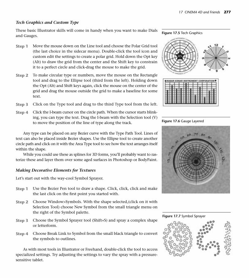
Tech Graphics and Custom Type
These basic Illustrator skills will come in handy when you want to make Dialsand Gauges.
Step 1 Move the mouse down on the Line tool and choose the Polar Grid tool(the last choice in the sidecar menu). Double-click the tool icon andcustom edit the settings to create a polar grid. Hold down the Opt key(Alt) to draw the grid from the center and the Shift key to constrainit to a perfect circle and click-drag the mouse to make the grid.
Step 2 To make circular type or numbers, move the mouse on the Rectangletool and drag to the Ellipse tool (third from the left). Holding downthe Opt (Alt) and Shift keys again, click the mouse on the center of thegrid and drag the mouse outside the grid to make a baseline for sometext.
Step 3 Click on the Type tool and drag to the third Type tool from the left.
Step 4 Click the I-beam cursor on the circle path. When the cursor starts blink-ing, you can type the text. Drag the I-beam with the Selection tool (V)to move the position of the line of type along the track.
Any type can be placed on any Bezier curve with the Type Path Tool. Lines oftext can also be placed inside Bezier shapes. Use the Ellipse tool to create anothercircle path and click on it with the Area Type tool to see how the text arranges itselfwithin the shape.
While you could use these as splines for 3D forms, you’ll probably want to ras-terize these and layer them over some aged surfaces in Photoshop or BodyPaint.
Making Decorative Elements for Textures
Let’s start out with the way-cool Symbol Sprayer.
Step 1 Use the Bezier Pen tool to draw a shape. Click, click, click and makethe last click on the first point you started with.
Step 2 Choose Window>Symbols. With the shape selected,(click on it withSelection Tool) choose New Symbol from the small triangle menu onthe right of the Symbol palette.
Step 3 Choose the Symbol Sprayer tool (Shift+S) and spray a complex shapeor letterform.
Step 4 Choose Break Link to Symbol from the small black triangle to convertthe symbols to outlines.
As with most tools in Illustrator or Freehand, double-click the tool to accessspecialized settings. Try adjusting the settings to vary the spray with a pressure-sensitive tablet.
17 CINEMA 4D and Friends 277
Figure 17.5 Tech Graphics
Figure 17.6 Gauge Layered
Figure 17.7 Symbol Sprayer

Making Repetitive Patterns
Step 1 Use the Bezier Pen tool to draw a shape and choose the stroke and fillcolors from the Color palette (Window>Color).
Step 2 If the Pattern Piece you are building has more than one object, groupthem together with Cmd+G (Ctrl+G).
Step 3 Select the Pattern piece (or Group) and Opt-drag (Alt-drag) a first copy,dropping the copy with the desired spacing. Once that first copy is cor-rectly positioned, you can press Cmd+D (Ctrl+D) for as many copiesas you want. If you want to constrain the movement of the first copyon a level line, hold down the Shift key after you begin the Opt-drag(Alt-drag).
Step 4 Press Command-A to selectthe row of pattern pieces, andCommand-G to group them.
Step 5 Repeat Step 3 to copy the rowsvertically.
The Tile shader within CINEMA 4Dwill handle most patterning jobs, butyour favorite vector application willhelp out when needs for more complexrepetitive bump maps or surface designsarise.
The uses for Illustrator in creatingimagery for surfacing are endless. Anyforms you create can easily be used tocreate patterns. The Pathfinder (Effect>Pathfinder) is particularly useful forgenerating fresh forms for logos. ThePaintbrush tool is great for adding cus-tom decorative trims to your textures.
278 CINEMA 4D
Figure 17.8 Repetitive Pattern
Figure 17.9 Shapes created with thePathfinder
Figure 17.10 Decorative Trims Using Illustra-tor’s Brush Tool
Figure 17.11 Decorative Edge Using anIllustrator Style
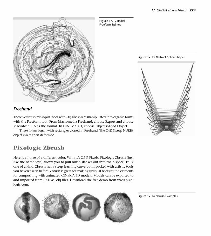
17 CINEMA 4D and Friends 279
Figure 17.12 RadialFreeform Splines
Figure 17.13 Abstract Spline Shape
Figure 17.14 Zbrush Examples
Freehand
These vector spirals (Spiral tool with 50) lines were manipulated into organic formswith the Freeform tool. From Macromedia Freehand, choose Export and chooseMacintosh EPS as the format. In CINEMA 4D, choose Objects>Load Object.
These forms began with rectangles cloned in Freehand. The C4D Sweep NURBSobjects were then deformed.
Pixologic Zbrush
Here is a horse of a different color. With it’s 2.5D Pixols, Pixologic Zbrush (justlike the name says) allows you to pull brush strokes out into the Z space. Trulyone of a kind, Zbrush has a steep learning curve but is packed with artistic toolsyou haven’t seen before. Zbrush is great for making unusual background elementsfor compositing with animated CINEMA 4D models. Models can be exported toand imported from C4D as .obj files. Download the free demo from www.pixo-logic.com.

Synthetik Studio Artist and Corel Painter
While Adobe Photoshop is the basic image-editing workhorse, two other appli-cations are must-have if you lean toward the fine arts and natural media. Theseapplications provide both unique elements for import into CINEMA 4D and cre-ative possibilities for postproduction.
Corel Painter has long been a champion in the natural media arena, and thenewest version has an improved interface. Painter’s inventive tools offer excit-ing texturing possibilities for the CINEMA 4D artist. Painter’s cool feature list in-cludes watercolors that actually run down the page, believable impastos, nozzlesthat spray multiple images, and the best fur brush around. An extra plus for 3D:Painter has an editor for custom designing warps and wefts of fabrics.
280 CINEMA 4D
Figure 17.15 Painter Nozzles Figure 17.16 Fabric Patterns in Painter
Figure 17.17 Painter Impasto Surface
Synthetik Studio Artist, a graphics synthesizer, is a massive set of illustrationand postproduction tools. If you want to create imaginative and original tex-tures, this is your weapon of choice. Its massive palette of tools in the naturalmedia genre is almost distracting. In addition, Studio Artist will use any of itstools to automatically generate markings over imported resource images. On thepostproduction side, animations created in CINEMA 4D can be opened in Stu-dio Artist and automatically processed with thousands of stylistic treatments for

17 CINEMA 4D and Friends 281
Figure 17.18 Studio Artist Brushes
a myriad of new versions of the original. Mac users can download a free demofrom www.synthetik.com.
Sources and Software for Splines
The web has many sources for free splines for vector and raster programs. Type“Free PS Custom Shapes” in a search engine such as Google. Free font dingbatsare also plentiful. Adobe Streamline can be useful for converting any raster imageinto vectors. Illustrator and Freehand have trace functions also.
Sound Solutions
Apple Computer’s Garageband and Soundtrack provide easy ways to make originalsounds and background music for your animations. GarageBand comes with theeconomical iLife package. Soundtrack ships with Final Cut Pro or you can purchaseit as a standalone application. Even if you have no music training, these amazingapplications will let you produce just the right sound for your 3D projects.
GarageBand
With GarbageBand, you can connect your own keyboard or guitar inputs (withextra hardware) and mix the different tracks into a song. If you don’t have yourown music input, GarageBand includes a keyboard for inputing your original tuneswith a mouse. In addition, GarageBand comes with a library of royalty-free loopsthat you can layer creatively. The loops include a wide choice of instruments and
Figure 17.19 Textures Painted in StudioArtist

drums. Since the loops are searchable by keyword, it’s easy to quickly find and mixappropriate sounds for your animation. For those who aren’t ready to go into morecomplex sound editing but need copyright-free and inexpensive music, this is it.
Soundtrack
Soundtrack is similar to GarageBand, but has a video window so you can matchthe music tracks you are creating to a QuickTime movie.
Open Soundtrack, and choose Window>Media Manager. To build a sound-track for your animation, drag the QuickTime you rendered out of CINEMA 4Dinto the upper left Video window. In the Media Manager, click any genre panelwhere you can choose the sounds to preview. When you find a sound you like,just drag and drop it into the soundtrack (Untitled Track 1). You can drag left orright to any starting point you like. (Hold down the Cmd key to bypass snap-ping for more accurate placement.) To loop the sound over and over, move themouse on the right edge and drag out multiples of the sound. Change the keyof the sound by dragging down to the desired key in the pulldown menu to theright of the record and playback controls at the top of the window. In that samewindow you can change the beats per minute, access the SMPTE timecode, con-trol the play of the project, and even record sound.
Try it! Choose Synths>A Bleep Odessey.aiff in the first track. Add a new trackwith Cmd+T and choose Drums>Bass Drum Pattern. Now here’s the ultimatelycool thing about Soundtrack—it automatically matches the tempo of anythingyou add to the existing beat. Add some more tracks. When you are finished mix-ing, just choose File>Export to QuickTime to create the soundtrack intact in theoriginal QuickTime or File>Export Mix to export a separate soundtrack.
To the Web with You, C4D!
Here are ways to show off your masterpieces on the web:
QuickTime
Choose QuickTime Movie Small from the Render Settings>Save panel for a varia-tion on the Cinepak codec, which will produce a small time-compressed file of fairquality. For a more lossless version (and a larger file size) choose QuickTime Big. Ifyou want to experiment with other choices that might work better with the colorand detail in your animation, choose QuickTime Movie and use the Options but-ton to access a pulldown menu of codecs. The Animation codec will usually workfine, but the color quality, detail quality, and motion quality that you require in aparticular movie will vary and other compression styles might work better. Ren-der out several different compression options and compare them. Compressionapplications like Sorensen Squeeze and Cleaner will be great helpers for efficientlycompressing your movies for the web.
282 CINEMA 4D

Using the FlashEx Plugin
FlashEx is a plugin that exports CINEMA 4D models as .swf files and even gen-erates the HTML file.
Because these exports are vector graphics, raster textures are not exportable.But interesting models exported in a variety of rendering modes and line stylescan add fresh looks for your Flash work.
Step 1 Place the FlashEx folder inside CINEMA 4D’s Plugins folder. The pluginshould show up in the Plugins list the next time you start CINEMA 4D.
Step 2 Choose the FlashEx plugin from the Plugins list.
Step 3 On the general page, click the Render button and the save location willappear in the File input box. Under Duration, enter the beginning andending frames you want to export. Under Optimize For, enter the sizeyou want the exported art to be. Choose a frame rate and a mode.
Step 4 Click the Background tab and set a background color.
Step 5 Click the Lines tab. In this page, you can experiment with different linewidths and colors.
Step 6 Click OK, and the .swf file will be saved to the specified Save location.
CINEMA 4D into Adobe ImageReady
Step 1 Make a folder on your desktop named Frames. In the Render SettingsOutput page, you might want to choose Manual to make a tiny movie.The example is 50 by 50. You’ll end up with an animated GIF, so theFrame Rate needs to be very low (5–7).
Step 2 On the Save page, click Path and navigate to the Frames folder you made.Change the Format to Photoshop PSD. Check Alpha channel if you wantto layer the image over other layers in Photoshop. Render the frames.
Step 3 Open Photoshop and click the Jump to ImageReady button at the bot-tom of the Toolbar. Choose File>Import>Folder as Frames and navigateto the Frames folder to import the rendered frames.
Step 4 Click the Play button if you want to preview the movie in ImageReady.To export the GIF, choose File>Save Optimized. In the dialog box, entera title for the GIF and under Format, choose Images Only or HTML andImages.
On the DVD: Open “BodyPainted Gif” in the MOVIES/STILLS folder.
17 CINEMA 4D and Friends 283
Figure 17.20 Web Element made withFlashEx Plugin

CINEMA 4D and Apple Final Cut Pro
CINEMA 4D animations are easily im-ported into Apple Final Cut Pro bychoosing File>Import>Files. Just clickthe Alpha check box when renderingout of CINEMA 4D, and objects journeyinto Final Cut Pro with beautiful edges.
OrganizingLibraries
After you get started in 3D, it won’t belong before you are drowning in a seaof files. CINEMA 4D models, texturesand image maps, sounds, fonts, andrendered projects will crowd your stor-age real estate.
Set up an organizational systemnow, and file faithfully after you finisha project. This little bit of forethoughtnow will save hours of unnecessarysearching in the future. Not only willorganized libraries save lots of time butthey are important for saving storagespace. Huge libraries of rarely used filescan be saved with a catalog to DVD.
The Browser
Place your models in a folder, and clickthe Browser tab in CINEMA 4D. Choose
284 CINEMA 4D
Figure 17.21 Sphere Painted in BodyPaintand Imported into ImageReady
Figure 17.22 C4D Rendering in Final Cut Pro
Figure 17.23 Organization Example

17 CINEMA 4D and Friends 285
Figure 17.24 C4D Browser Catalog
Figure 17.25 Iview Catalog

File>Import Directory from the Browser Menu. This collection of models mayalso be saved as a Catalog (File>Save Catalog). Drag and drop models to the Edi-tor window or materials to the Materials Manager.
iView Media Pro
Drag and drop a folder of (almost) any kind of files onto the iView icon on thedock, and you’ll get a blazingly fast thumbnail preview. Image files, QuickTimemovies, sound files, fonts, just to name a few, can be quickly browsed with thisindespensible application. Not only is this program great for organization, it’s asuper tool for client presentations. Students or teachers can drop a folder con-taining an entire semester’s work (random mixes of raster, vector, QuickTimes,even SWFs) into iView for quick and easy presentation or grading. (Note thatiView does not preview CINEMA 4D files, only rendered models and scenes, butyou have the CINEMA 4D Browser for that.)
Hardware Friends
There are catalogs full of hardware toys, but here are the digital artist’s bare ne-cessities:
• A decent digital camera.
• A scanner.
• A digital tablet.
• A stopwatch.
On the DVD: Chapter 17>EXTRA!EXTRA!>InDepth>More Tools and Toys.pdf fora list of cool toys that aren’t necessary but add bells, whistles, and fun to the 3Dprocess.
286 CINEMA 4D

18Tips on Type
Figure 18.1
A fter an introduction to making text objects in CINEMA 4D, this sectionwill look at creative ways to glorify letters and numbers in 3D space andtime. The names of comicbook superheros were extruded in space long be-
fore the age of the desktop designer. Enjoy those 3D Archi-Types, and then exploresome new techniques for appropriate and inventive typography. Be sure to checkout the resources on typography on the DVD. Building and animating 3D lettersis one thing, but choosing type and applying the wonders of CINEMA 4D in re-gard to the design process is another. Not knowing the language of typography(with its foreign words like serif, kern, and counterspace) can cause the most clever3D artist to lose credibility and clients in the professional world. You can neverknow enough about the communicative qualities of typestyles and the beauty ofletterforms. If your work will involve typography, make it your business to learnabout it. If you can’t take design classes, there are many excellent, free Internet re-sources on designing with type.
On the DVD: See Chapter 18>EXTRA!EXTRA!>References for pointers to more in-formation about designing with type.
The Basics of Text Splines
Step 1 Choose File>New and save the file as TextPlay in your Models folder(File>Save As).
◆ Tip: In these projects, you may or may not have the indicatedfonts available on your system. If you don’t have the specifiedfonts, choose a similar font. Natu-rally, your efforts may look differ-ent from the examples. The qualityof the spline will determine thequality of the 3D Type, so be awarethat some fonts (like some freehandcrafted Internet offerings)may have troublesome splines.Among the many trustworthytypefaces and dingbats shared forfree or nominal fees are those atwww.larabiefonts.com. Some ofthem are used in these exercisesif you want to download them.
287
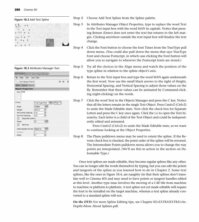
Step 2 Choose Add Text Spline from the Spline palette.
Step 3 In Attributes Manager Object Properties, type to replace the word Textin the Text input box with the word MAN in capitals. Notice that press-ing Return (Enter) does not enter the text but returns to the left mar-gin. Clicking anywhere outside the text input box will finalize the textchange.
Step 4 Click the Font button to choose the font Times from the TrueType pulldown menu. (You could also pull down the menu that says TrueTypeFont and choose Postscript, in which case clicking the Font button willallow you to navigate to wherever the Postscript fonts are stored.)
Step 5 Try all the choices in the Align menu and watch the position of thetype spline in relation to the spline object’s axis.
Step 6 Return to the Text input box and type the word MAN again underneaththe first word. Now use the small black arrows to the right of Height,Horizontal Spacing, and Vertical Spacing to adjust those values on thefly. Remember that these values can be animated by Command-click-ing (right-clicking) on the words.
Step 7 Click the word Text in the Objects Manager and press the C key. Noticethat all the letters remain in the single Text Object. Press Cmd+Z (Ctrl+Z)to undo the Made Editable state. Now click the check box for SeparateLetters and press the C key once again. Click the (+) to open the Text hi-erarchy. Each letter is a child of the Text Object and could be independ-ently edited and animated.
Press Cmd+Z (Ctrl+Z) to undo the Made Editable state, as we wantto continue looking at the Object Properties.
Step 8 The Plane pulldown menu may be used to orient the spline. If the Re-verse check box is checked, the point order of the spline will be reversed.The Intermediate Points pulldown menu allows you to change the waypoints are interpolated. (We’ll see this in action in the section on De-formable Type.)
Once text splines are made editable, they become regular splines like any other.You can no longer edit the words themselves by typing, but you can edit the pointsand tangents of the spline as you learned how to do in Chapter 2. Some textsplines, like the ones in Figure 18.4, are naughty (in that their splines don’t trans-late well to Cinema 4D) and may need to have points or tangent handles editedat this level. Another type issue involves the moving of a C4D file from machineto machine or platform to platform. A text spline not yet made editable will requirethe font to be installed on the target machine, whereas a text spline already con-verted to a standard spline will not.
On the DVD: For more Spline Editing tips, see Chapter 02>EXTRA!EXTRA!>In-Depth>More About Splines.pdf.
288 Cinema 4D
Figure 18.2 Add Text Spline
Figure 18.3 Attributes Manager Text

I Have No Words
Despite all that editing, a render at this point would look like a panther deep in acoal mine. Remember that splines are invisible and are used as elements to creategeometry. For now, create an Extrude NURBS and drop the text spline into it. Youmay want to review the Extrude NURBS and Sweep NURBS tools in Chapter 3.
Making Text Behave in CINEMA 4D
Step 1 Return to the Text input box and replace the word Man with MOON(all caps). Change the Type to TrueType>Helvetica. Uh oh—looks likesomeone took a bite out of the Os.
Step 2 Make the Text Object Editable, select each O. Choose Structure>EditSpline>Soft Interpolation. You will still need to tweak a few points andtangent handles. It is inevitable that you’ll occasionally run into weirdsplines, but they can be manually adjusted.
Deformable Type
Study Figure 18.6. The first A on the left has no apparent problems since it is staticand was never intended to bend. The second A from the left became rather cubist-style for lack of enough subdivisions when it was subjected to a bend deformer.Unfortunate. The third and fourth As are just right. First the Intermediate Pointsof the Text spline were changed to Natural. Then the Subdivision of the ExtrudeNURBS object was increased in Object Properties. In the Caps panel, Regular Gridwas checked and the Width was increased. How much these values are increaseddepends on the letter itself and the degree of the bend, so you will have to exper-iment and test-render each situation.
18 Tips on Type 289
Figure 18.4 Naughty Splines
Figure 18.5 Fixed “O”s
Figure 18.6 Not Deformed, BadlyDeformed, Well Deformed

And Now, Some Creative Text Messaging
The whole point of typography is communication. In the 2D world, a single let-ter can speak volumes and send a message without even joining others in thespelling of a word. The typestyle itself—by virtue of its curves, overall shape, mo-tion, or historical reference—may say seriously businesslike, funky, frivolous, ornostalgic. The 2D artist may add further communication value by rendering thetype in colors, patterns, or stylistic treatments that remind the typographic au-dience of times, places, emotions, or attitudes.
In the CINEMA 4D environment, this ability to tell a story with letters increasesexponentially. The capability to animate position, rotation, scale, color, transpar-ency, and other attributes provides infinitely more ways to bring type to life. Let-ters can be made to twitch and wiggle, or flop over and die. So a word of warningis in order. It’s not always about making type fancy but rather about using it to saywhat needs to be said. Sometimes a restrained motion of the most plain or tradi-tional typestyle is called for. Some of your type may speak with quiet elegance,while other letters play boisteriously. Enjoy and explore the differences.
Sleek and Sophisticated
The strength of classic type and 3D tools are a powerful combination. Deceptivelysimple, this genre of 3D typography can take hours of tweaking before every ma-terial surface, highlight, and movement comes together in a perfect gestalt. Let’sreview basic Extrude NURBS skills with this corporate logotype.
Step 1 In a new C4D file, choose Spline>Add Text Spline and type CORPCO(all caps) in the Text input box. Choose the Charcoal TrueType font.(If you don’t have Charcoal, choose a similar blocky, sans serif font.)Increase the Horizontal Spacing to 20m. (Any time type will be seenfrom side angles, increasing the horizontal spacing will help maintainreadability.)
Step 2 Choose an Extrude NURBS object, and drop the text spline inside. Se-lect the Extrude NURBS object and in the Attributes Manager, increasethe Z Movement to 50.
Step 3 Click the Caps panel, and enter Fillet Caps with Steps 1, Radius 5 forboth Start and End. Leave the Fillet Type on Convex.
Step 4 Create two silver metal materials, one leaning toward blue and one to-ward green. Make sure the blue material has a high, narrow Specularhighlight and set the color to a bright blue. Turn on Reflection for thegreen material and leave the Brightness high. Turn on Environment andnavigate to any file from GOODIES>MATERIALS>HDRIImages. Experi-ment with the Brightness and Mix sliders to get the right look. (Laterif you want to render the animation with HDRI luminance, return toChapter 12>EXTRA!EXTRA!>InDepth for a review on how to set that
290 Cinema 4D

up.) Place the blue material on the Extrude NURBS first, and place thegreen material on the Extrude Nurbs last. Select the green material tag,and in Tag Properties type C1 in the selection box.
Step 5 Using the skills you learned in Chapters 6 and 11, set up lights and a cam-era to fly up to the logo. (Turn on Title Safe in Preferences>Viewport andkeep the type within those guidelines.) Set up basic Main/Fill lighting,and then add a light to animate across the top or bottom faceted edgeof the letters. Experiment with highlights as finishing touches. If this isrendered out with an alpha channel, it can be layered over video footage.Don’t be surprised if it takes a long time to get it right. Even the most sim-ple logo can require numerous test renderings to balance the delicate in-teractions of surface, timing, camera, and lights.
On the DVD: See Chapter 18>MOVIES/STILLS for example movies.
◆ Tips:• What about kerning in C4D? The spacing you made between letters in
the Horizontal Spacing box is called tracking (equal space added betweenletters). What if you needed to kern, or independently adjust the spacebetween any two letters? That must be done manually, which is anothergood reason to check Separate Letters when you make the text spline.
• While selecting objects in the editor window is usually OK, it’s a bad ideawith text objects. You’ll probably end up with only a Cap selected in-stead of the entire 3D object.
Text on Illustrator Paths
Step 1 Create a new C4D file (File>New) and save it as TextSpiral.c4d into yourModels folder (File>Save As). In the Objects Manager menu, choose File>Load Object. Navigate to LittleGirl.AI from the Chapter 18>C4D Filesfolder. It’s important to note that this file was saved out of Adobe Illus-trator with Illustrator 8 file compatibility. Also, in Illustrator, select anytext you create and choose Type>Create Outlines so the type will appearin CINEMA 4D.
18 Tips on Type 291
Figure 18.7 CORPCO
Multiple Materials on Text
Drop the overall Material on thename of an Extrude NURBS objectfirst. Then drop additional materi-als. (Materials without selectionsshould go to the left of those withselections.) In the Tag Propertiesselection box, type R1 for Round-ing 1 (the front), R2 for Rounding2 (the back), C1 for Cap 1 (FrontCap), and C2 for Cap 2 (backcap). Once the Text object hasbeen made editable by pressingthe C key, you can also makepolygonal selection sets and as-sign different materials to those.
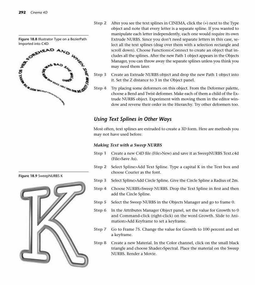
Step 2 After you see the text splines in CINEMA, click the (+) next to the Typeobject and note that every letter is a separate spline. If you wanted tomanipulate each letter independently, each one would require its ownExtrude NURBS. Since you don’t need separate letters in this case, se-lect all the text splines (drag over them with a selection rectangle andscroll down). Choose Functions>Connect to create an object that in-cludes all the splines. After the new Path 1 object appears in the ObjectsManager, you can throw away the separate splines unless you think youmay need them later.
Step 3 Create an Extrude NURBS object and drop the new Path 1 object intoit. Set the Z distance to 3 in the Object panel.
Step 4 Try placing some deformers on this object. From the Deformer palette,choose a Bend and Twist deformer. Make each of them a child of the Ex-trude NURBS object. Experiment with moving them in the editor win-dow and reverse their order in the Hierarchy. Try other deformers too.
Using Text Splines in Other Ways
Most often, text splines are extruded to create a 3D form. Here are methods youmay not have used before.
Making Text with a Sweep NURBS
Step 1 Create a new C4D file (File>New) and save it as SweepNURBS Text.c4d(File>Save As).
Step 2 Select Spline>Add Text Spline. Type a capital K in the Text box andchoose Courier as the font.
Step 3 Select Spline>Add Circle Spline. Give the Circle Spline a Radius of 2m.
Step 4 Choose NURBS>Sweep NURBS. Drop the Text Spline in first and thenadd the Circle Spline.
Step 5 Select the Sweep NURBS in the Objects Manager and go to frame 0.
Step 6 In the Attributes Manager Object panel, set the value for Growth to 0and Command-click (right-click) on the word Growth. Slide to Ani-mation>Add Keyframe to set a keyframe.
Step 7 Go to Frame 75. Change the value for Growth to 100 percent and seta keyframe.
Step 8 Create a new Material. In the Color channel, click on the small blacktriangle and choose Shader>Spectral. Place the material on the SweepNURBS. Render a Movie.
292 Cinema 4D
Figure 18.8 Illustrator Type on a BezierPathImported into C4D
Figure 18.9 SweepNURBS K

Try using a text spline as the profile for a Sweep NURBS (start with an ArcSpline as the path), and keyframe the Growth value.
On the DVD: See Chapter 18>MOVIES/STILLS for examples of these techniques.
Easily Animated Flat Letters
Text splines could also be placed in Loft NURBS object to create a totally flat let-ter. But, here’s a more versatile way to make flat letters that can behave organi-cally in the 3D space.
Step 1 Create a new C4D file (File>New) and save it as A_Flat_Letter.c4d (File>Save As).
Step 2 From the top menu, choose Primitive>Plane. In the Attributes Man-ager, change the Width to 300 and the Orientation to –Z.
Step 3 Press the C key to make the plane editable.
Step 4 In the Materials Manager, choose File>New Material. In the Color chan-nel, navigate to GOODIES>MATERIALS>TYPEIMAGES>A_Color.psd. Ac-tivate the alpha channel and navigate to GOODIES>MATERIALS>TYPEIMAGES>A_Alpha.psd. Click the Invert check box on the Alpha page.
Place the material on the plane.
Step 5 With the plane still selected, choose the Use Polygons tool, and thenchoose Structure>Edit Surface>Crumple. Now animate some deformers
18 Tips on Type 293
Figure 18.10 SuperText

on the flat letter. If your edges begin to get too chunky, you can alwaysdrop the plane into a HyperNURBS for instant smoothing.
Step 6 Return to the material and place some patterns in the Transparencychannel.
This technique offers some additional ways to play. Think about using AdobePhotoshop filters to create creative edges for the Alpha channel. (The PhotoshopPDF on the DVD shows you how.) Revisit the Color channel and experiment withdifferent tile patterns in the Transparency channel. This technique is great for cre-ating wispy typographic floaters to invade your 3D space as secondary noise.
On the DVD: See Chapter 18>MOVIES/ STILLS for examples of these techniquesand Chapter 17>EXTRA!EXTRA!>InDepth for a PDF on Photoshop Skills.
Type Forms: Finishing Touches and Creative Play
Beyond the choice of typestyle and modeling tool used to make a 3D type form,there are many ways to individualize type. When the situation calls for sophisti-cation, you may be using simple, elegant materials and adjusting caps and round-ing in subtle ways to catch the light in a scene. For more stylized or edgy type,you’ll experiment with color, patterns, cap/rounding treatments, or radically dis-torted text meshes.
Study the files from the Chapter 18>C4DFiles>Typeplay folder. Study the Capspanel settings and Material settings. (There are two Caps_Rounding files: Caps_
294 Cinema 4D
Figure 18.11 Wispy Floating Type Figure 18.12 Deformed Type

RoundMat.c4d has been made editable to maintain the typestyle, and Caps_RoundSet.c4d has not been made editable so you can inspect the Caps and Roundingsettings.)
Open the Chapter 18>C4DFiles>ComplexSplines folder. In the HD.c4d file, theobject was created by first making the H and D splines editable and choosing Func-tions>Connect. The eight-pointed star was then created and made editable, andFunction>Connect was chosen again. The text object inside the Extrude NURBSwas selected and the top and bottompoints of the star were moved with thegreen move handle. In the Five Frag-ments.c4d file, the text spline was madeeditable and the points and tangents ad-justed to create the fragmented forms.CINEMA 4D does fine with these typesof nonoverlapping splines.
To create complex spline combina-tions that involve combining shapesand joining points, you are better offcreating the complex outline in Illustra-tor, saving the file as Illustrator 8, andchoosing Objects>Load Object to im-port the new spline into C4D. Fan-cyM.c4d started with a spline created byusing the pathfinder tool in Illustrator.
18 Tips on Type 295
Figure 18.13 Rounding on Extrude NURBS
Figure 18.14 Text Caps
Figure 18.15 Text Materials
Figure 18.16 HD, Splines Adjusted inCINEMA

296 Cinema 4D
Figure 18.17 Complex Splines in Illustrator Figure 18.18 Complex Splines Loaded into C4D
Figure 18.19 Five Fragments, SplinesAdjusted in CINEMA
Figure 18.20 Dragon Queen, Polys Extruded Figure 18.21 Text Object, Manipulated andObjects Added (Toothy A)
Figure 18.22 Cheese Boolean

In Chapter 18>C4Dfiles, open the Stylized Text folder. These letters are read-able but manipulated as 3D objects for the sake of novelty.
Now open the Chapter 18>C4DFiles>TypeAsArt folder. There’s a place outthere on the edge where type is less concerned with readability of words but be-comes more about communicating as an art element.
Even if they are not readable, typographical elements can still have muchto say. At this point, play becomes the work of the most serious designer. Thosewho are willing to let go, take chances, and spend many hours experimentingwill go far in this genre.
18 Tips on Type 297
Figure 18.23 Numbers on a String Figure 18.24 S Beads
Figure 18.25 Flag for the Digital Age
Figure 18.26 Moonman Duplication
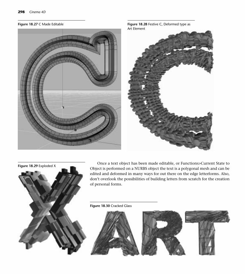
Once a text object has been made editable, or Functions>Current State toObject is performed on a NURBS object the text is a polygonal mesh and can beedited and deformed in many ways for out there on the edge letterforms. Also,don’t overlook the possibilities of building letters from scratch for the creationof personal forms.
298 Cinema 4D
Figure 18.27 C Made Editable Figure 18.28 Festive C, Deformed type asArt Element
Figure 18.29 Exploded X
Figure 18.30 Cracked Glass

Animated Type Effects
Happy Trails to “U”
Step 1 Create a new C4D file (File>New) and save it as Trailing U.c4d (File>Save As). Set the project length to 200 frames.
Step 2 Select Spline>Add Text Spline. Type a capital U in the Text box andchoose Impact or another chunky sans serif font.
Step 3 Choose NURBS>Extrude NURBS and drop the Text Spline inside. Namethe Extrude NURBS object U DADDY.
Step 5 Control-drag 4 copies of U DADDY, naming them U CHILD 1, U CHILD2, U CHILD 3, and U CHILD 4.
Step 6 Command-click (right-click) on U CHILD 1 and drag to New Expression>Xpresso Expression. Drag the names U DADDY and U CHILD 1 into theXpresso Editor window. Enlarge the window of the U DADDY Node.
Step 7 Move the mouse to the blue input square of U DADDY and choose His-tory Level. In the Attributes Manager, enter Relative Reference as Ref-erence Mode, 10 as History Depth, and 10 as the History Level.
Step 8 Move the mouse to the red output square of U DADDY and choose Pre-vious Position.
Step 9 Move the mouse on the blue input square of U CHILD 1 and choose Co-ordinates>Global Position>Global Position. With the U Child 1 Node se-lected, set the Reference Mode to Relative and enter 10 for History Depth.Draw a connector line from U DADDY’s Previous Position port to UCHILD 1’s Global Position port.
Step 10 Control-drag the Xpresso Expression tag from U CHILD 1 to U CHILD2, U CHILD 3, and U CHILD 4.
Step 11 Use the Move tool to drag U DADDY around thescreen, and you should see the U children follow.Animate U DADDY to move up and down acrossthe screen. If you want the children to catch upwith the daddy by the end of the animation, leavesome frames at the end of the animation so therewill be time for that to happen.
Step 12 Create a new material in a solid color. Make fourcopies of the material, and make each one in-creasingly transparent. Place the solid on UDADDY and the material copies on the U chil-dren, with U CHILD 1 being least transparentand U CHILD 4 being most transparent.
18 Tips on Type 299
Figure 18.31 U Daddy with Children Trailing

■ Springboard! Make a more interesting version of this project by addinga Previous Rotation output port to the U DADDY Node. Then add an in-put port to the U CHILD 1 node for Coordinates>Global Rotation>GlobalRotation. (If you make this addition to the initial Trailing U file, be sure toremove the tags previously copied to the children and copy the new editedtag so all the tags will be updated.) Any animation of position or rotationfor U DADDY will be copied by the children as they follow along. See theexamples on the DVD.
On the DVD: Don’t miss the Chapter 18>EXTRA!EXTRA!>InDepth! folder. Thereare examples of creative type play, including Fun with Dingbats.
300 Cinema 4D
Figure 18.32 Dingbats1&2
Figure 18.33 Helvetica, reproduced bypermission of Chris Cousins
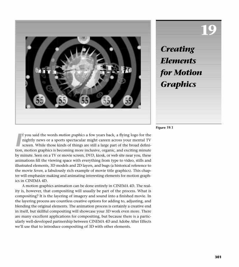
19CreatingElements for MotionGraphics
301
Figure 19.1
I f you said the words motion graphics a few years back, a flying logo for thenightly news or a sports spectacular might careen across your mental TVscreen. While those kinds of things are still a large part of the broad defini-
tion, motion graphics is becoming more inclusive, organic, and exciting minuteby minute. Seen on a TV or movie screen, DVD, kiosk, or web site near you, theseanimations fill the viewing space with everything from type to video, stills andillustrated elements, 3D models and 2D layers, and bugs (a historical reference tothe movie Seven, a fabulously rich example of movie title graphics). This chap-ter will emphasize making and animating interesting elements for motion graph-ics in CINEMA 4D.
A motion graphics animation can be done entirely in CINEMA 4D. The real-ity is, however, that compositing will usually be part of the process. What iscompositing? It is the layering of imagery and sound into a finished movie. Inthe layering process are countless creative options for adding to, adjusting, andblending the original elements. The animation process is certainly a creative endin itself, but skillful compositing will showcase your 3D work even more. Thereare many excellent applications for compositing, but because there is a partic-ularly well-developed partnership between CINEMA 4D and Adobe After Effectswe’ll use that to introduce compositing of 3D with other elements.
On the DVD: The C4D_AE.pdf in the Chapter 19>EXTRA!EXTRA!>InDepth willprovide introductory After Effects skills to get you started with compositing.
302 CINEMA 4D
Design and Flow
Artistically, the same art elements and design principlesused in fine art or graphic design apply to motion graph-ics. The difference is that these elements and principlesnow apply across time and interact with motion andsound. The design process has much more depth andcomplexity. As you begin to create motion graphics, thesesimple guidelines may help you create cohesive and inter-esting visuals.
• Variety and Contrast. Kindergarten art teachers some-times tell their young artists to include somethingsmall, medium, and large in their designs. Look atmotion graphics and you’ll see the same principle atwork. Variation of size, value, and other kinds of ele-ments keep things interesting.
You might ask yourself, “What kind of element do I need to contrast against what I already have?”For example, sharp, mechanical edges might be bestshowcased against soft, organic blur. Geometricsmight call out for curvilinear elements, or large, slowlymoving, heavy forms might need itchy-scratchy, rap-idly twitching lines to complement them. In 3D ani-mation, the word for variety is randomization.
• Unity. Repeating some kinds of elements across theframe and across time can act as “cosmic visual glue”to unify your design. Repeating typestyles, colors,shapes, sounds, and kinds of motion throughout thepiece reinforces the sense of design purpose.
• Direction and Patterns of Flow. What directional pathsor 3D forms will define the motion? Get out your realpaper sketchbook. Use a real pencil and doodle roughstoryboards, using little arrows and primitives to thinkabout how things will move in space. Ask yourself the
right questions before you begin, like “How will I usemotion and speed to affect the viewer?” Think abouthow motion functions as a design element. Motionpaths will serve as the structure of the design. Start ana-lyzing motion graphics, and think about the implica-tions of motion paths as they move across, toward you,and slowly away. Experiment with motion and counter-motion. For example, if one type element enters fromthe left, another might enter from the right to meet it,but with slightly different timing or in a different color.
• Timing is everything. Listen to some jazz. Use your F-Curves to massage visual happenings over time.Syncopation, jitter, drumbeats, tension and repose,ebb, and smooth, slow flow are all inspiration forlively moving graphics.
• Stars, Supporting Cast, and Extras. Decide up frontwhat elements will be the stars and secondary starsin your visual production. Then, find ways to “knockback” all the extras so that they provide richness,noise, and texture but don’t compete with what youhave to say. If all the colors in your design are intense,nothing will stand out. In motion graphics, an ele-ment floating almost transparently though the spacecan have much more artistic power than if all theelements are equally articulated. Use blur and trans-parency, dulling of color, and diminishing size toreduce the importance of subliminal layers.
• Purpose. Every element should have a reason to bein the space. It’s tempting to throw in that cool 3Dwidget you just made. Even abstract objects or visualnoise should contribute to the message. If not, use itanother day when it is appropriate.
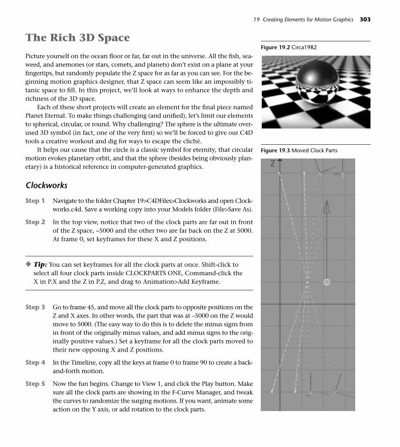
The Rich 3D Space
Picture yourself on the ocean floor or far, far out in the universe. All the fish, sea-weed, and anemones (or stars, comets, and planets) don’t exist on a plane at yourfingertips, but randomly populate the Z space for as far as you can see. For the be-ginning motion graphics designer, that Z space can seem like an impossibly ti-tanic space to fill. In this project, we’ll look at ways to enhance the depth andrichness of the 3D space.
Each of these short projects will create an element for the final piece namedPlanet Eternal. To make things challenging (and unified), let’s limit our elementsto spherical, circular, or round. Why challenging? The sphere is the ultimate over-used 3D symbol (in fact, one of the very first) so we’ll be forced to give our C4Dtools a creative workout and dig for ways to escape the cliché.
It helps our cause that the circle is a classic symbol for eternity, that circularmotion evokes planetary orbit, and that the sphere (besides being obviously plan-etary) is a historical reference in computer-generated graphics.
Clockworks
Step 1 Navigate to the folder Chapter 19>C4DFiles>Clockworks and open Clock-works.c4d. Save a working copy into your Models folder (File>Save As).
Step 2 In the top view, notice that two of the clock parts are far out in frontof the Z space, –5000 and the other two are far back on the Z at 5000.At frame 0, set keyframes for these X and Z positions.
◆ Tip: You can set keyframes for all the clock parts at once. Shift-click toselect all four clock parts inside CLOCKPARTS ONE, Command-click theX in P.X and the Z in P.Z, and drag to Animation>Add Keyframe.
Step 3 Go to frame 45, and move all the clock parts to opposite positions on theZ and X axes. In other words, the part that was at –5000 on the Z wouldmove to 5000. (The easy way to do this is to delete the minus signs fromin front of the originally minus values, and add minus signs to the orig-inally positive values.) Set a keyframe for all the clock parts moved totheir new opposing X and Z positions.
Step 4 In the Timeline, copy all the keys at frame 0 to frame 90 to create a back-and-forth motion.
Step 5 Now the fun begins. Change to View 1, and click the Play button. Makesure all the clock parts are showing in the F-Curve Manager, and tweakthe curves to randomize the surging motions. If you want, animate someaction on the Y axis, or add rotation to the clock parts.
19 Creating Elements for Motion Graphics 303
Figure 19.2 Circa1982
Figure 19.3 Moved Clock Parts

Here’s the truly cool thing. You can adjust the editor window view, the F-Curves, or the overall values of any attributes in the Attributes Coordinates on thefly while the animation is playing. Of course, if you want to keyframe changes overtime, stop the play and set the current time for keyframing. While it’s importantthat you know how to do this kind of thing manually, plugins like DiTOOLS,Jenna, and Loco are awesome tools for animating organic multiples in space.
On the DVD: Study the example file ClockParts.c4d in Chapter19>EXAMPLESand the movie ClockParts.mov in Chapter 19>MOVIES/STILLS.
Rendering a Single Layer for After Effects
All you have to do to render a single layer for After Effects compositing is checkthe Alpha check box on the Save page in Render Settings. The background willbe clear, and the edges of the objects smooth. The Alpha checkbox creates a pre-multiplied alpha. In some video compositing situations antialiasing can causean unexpected edge behavior, in which case you should choose Straight Alphainstead. Stay away from Floors, Skies, Backgrounds, or Foregrounds when ren-dering alpha channels, as these objects block out the entire channel.
Once you have a set of clock parts that has decent timing, render it with analpha channel. If you want a more dense array of clock parts in the final After Ef-fects composition, you could adjust the F-Curves and render several layers withdifferently timed files. In AE, you will be able to control the size and position ofeach set of clock parts but not the rotation of each individual object, so the rota-tion needs to be randomized in CINEMA 4D. If you wish, you can just make acopy of the clock parts and place a set on each side of the scene. Exactly wherethey are positioned is up to you. You’ll need to be sure that the camera doesn’t seeone of the clock parts flying through the solid glass sphere we are about to add.
Creating the Centroid
Step 1 Continue working in the Clockworks file, but hide the CLOCKPARTSONE objects by clicking the gray visibility dot to red.
Step 2 Choose a Sphere primitive, and give it a radius of 1000. Command-clickon the Sphere and choose New Tag>Display Tag. In Tag Properties, chooseWireframe mode.
Step 3 Copy the the Spiny ClockPart object (inside CLOCKPARTS ONE) to thetop of the list, make it editable by pressing the C key, and move its axisto its center. (You may need to use Frame Selected Elements to find it.)
Step 4 Select the Model tool, and enter 0, 0, 0 for the object’s coordinates.
Step 5 Remove the object’s animation tracks and keys in the timeline. (Makesure the Timeline lock is locked, and drag the Spiny Clockpart into the
304 CINEMA 4D
Figure 19.4 Spiny ClockPart’s Axis Moved toCenter

Timeline. Drag a rectangular selection over the all the keys and typeDelete.)
Step 6 Repeat Steps 3–5 with the Big Clock Part.
Step 7 Select the Sphere and choose Frame Selected Elements.
Step 8 Scale both elements so they fit the outside of the sphere, and rotate themas in Figure 19.5.
Step 9 Create a clear glass material with a refraction of 2 (the BhodiNUT Banjishader will do nicely), and place it on the Sphere.
Step 10 Make the two clockparts children of the Sphere.
Step 11 Animate the Sphere to rotate 360º on the H. Add some Pitch rotationif you like.
Step 12 Place a target camera in the scene and drag the central Sphere as thetarget. Set up the View in the upper left window, and position the cam-era so that everything looks good when you play the animation.
Step 13 Animate the camera to move in slowly so that the Centroid ends upbeing larger at the end of the animation.
Step 14 Go ahead and set up some basic lighting, and place a strong backlight be-hind the Centroid to show off the glass. You’ll want to adjust the light-ing after all the elements are placed and animated.
19 Creating Elements for Motion Graphics 305
Figure 19.5 Target Camera’sStarting (top) and Ending(bottom) Positions
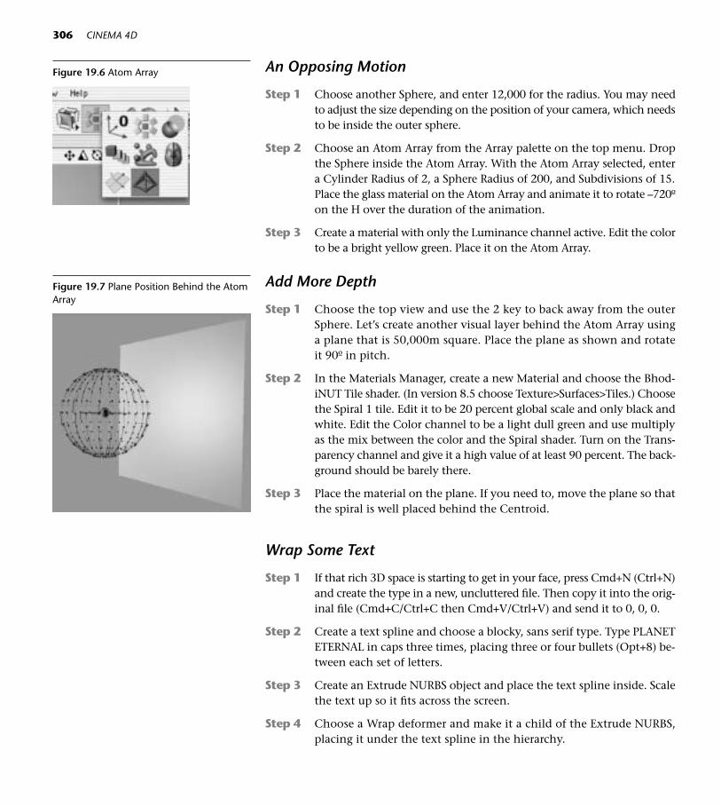
An Opposing Motion
Step 1 Choose another Sphere, and enter 12,000 for the radius. You may needto adjust the size depending on the position of your camera, which needsto be inside the outer sphere.
Step 2 Choose an Atom Array from the Array palette on the top menu. Dropthe Sphere inside the Atom Array. With the Atom Array selected, entera Cylinder Radius of 2, a Sphere Radius of 200, and Subdivisions of 15.Place the glass material on the Atom Array and animate it to rotate –720ºon the H over the duration of the animation.
Step 3 Create a material with only the Luminance channel active. Edit the colorto be a bright yellow green. Place it on the Atom Array.
Add More Depth
Step 1 Choose the top view and use the 2 key to back away from the outerSphere. Let’s create another visual layer behind the Atom Array usinga plane that is 50,000m square. Place the plane as shown and rotateit 90º in pitch.
Step 2 In the Materials Manager, create a new Material and choose the Bhod-iNUT Tile shader. (In version 8.5 choose Texture>Surfaces>Tiles.) Choosethe Spiral 1 tile. Edit it to be 20 percent global scale and only black andwhite. Edit the Color channel to be a light dull green and use multiplyas the mix between the color and the Spiral shader. Turn on the Trans-parency channel and give it a high value of at least 90 percent. The back-ground should be barely there.
Step 3 Place the material on the plane. If you need to, move the plane so thatthe spiral is well placed behind the Centroid.
Wrap Some Text
Step 1 If that rich 3D space is starting to get in your face, press Cmd+N (Ctrl+N)and create the type in a new, uncluttered file. Then copy it into the orig-inal file (Cmd+C/Ctrl+C then Cmd+V/Ctrl+V) and send it to 0, 0, 0.
Step 2 Create a text spline and choose a blocky, sans serif type. Type PLANETETERNAL in caps three times, placing three or four bullets (Opt+8) be-tween each set of letters.
Step 3 Create an Extrude NURBS object and place the text spline inside. Scalethe text up so it fits across the screen.
Step 4 Choose a Wrap deformer and make it a child of the Extrude NURBS,placing it under the text spline in the hierarchy.
306 CINEMA 4D
Figure 19.6 Atom Array
Figure 19.7 Plane Position Behind the AtomArray

Step 5 Using the Scale tool, enlarge the Wrap Deformer object until all the typeis visible. If necessary, further adjustments can be made with the de-former’s orange interactive handles. The Text splines could also be scaled.Rename the Extrude NURBS as PLANET ETERNAL TEXT.
Step 6 You will also need to make the Extrude NURBS object editable and repo-sition it’s axis in the center. In the Top view, use the grid to center the Ex-trude NURBS object around 0,0,0. Then use the Object Axis tool and theMove tool to center the axis. Choose the Object tool when you are fin-ished. With the PLANET ETERNAL TEXT returned to the original file withthe spheres, set all its coordinates to 0,0,0 and animate the type to rotatecounterclockwise (-360) around the centroid.
19 Creating Elements for Motion Graphics 307
Figure 19.8 Wrap Deformer on Text
As your RAM allows, add a few more elements of your choice. See the examplemovie on the DVD in Chapter 19>MOVIES/STILLS>EternalPlanet.mov. In the ex-ample movie, two orbits of semitransparent clockparts (using the Arrange function)were added around the Centroid.
On the DVD: Study the example file EternalPlanet.c4d in Chapter 19>EXAMPLES.
The After Effects Plugin
The After Effects plugin is located in MAXON>CINEMA R8>ExchangePlugins>After Effects. You should install the proper version for your After Effects (5 or5.5, Mac or PC). Run the .sit file and drop the plugin in your After Effects Plug-ins folder.
Setting Up A Multi-Pass Rendering
Step 1 In the Objects Manager, Shift-click to select the two clock parts that youused to make the metal rings around the Centroid sphere. Command-click (right-click) on one of them and drag down to New Tag>Composit-ing Tag. Click the Object tab, and select Object Buffer 1.

Step 2 In the Render Settings Save page, check the After Effects file check box.
Step 3 In the Render Settings, click Multi-Pass page. Use the Channels pull-downmenu to the right to select which information you want rendered sepa-rately into AE. For this example, choose Object Buffer and click OK toGroup ID 1, but notice all the other choices you have.
Step 4 Back on the Multi-Pass page, pull down to All in the Separate Lightsmenu, and 1 Channel in the Mode menu. Render the file.
308 CINEMA 4D
On the DVD: Working with Multi-Pass layers in After Effects is discussed in C4D_AE.pdf in the Chapter 19>EXTRA!EXTRA!>InDepth folder on the DVD.
Explore the additional motion graphics projects in Chapter 19>EXTRA!EX-TRA!>InDepth. They contain embedded explanations in their Objects Managersor have accompanying instructional PDF files. The Planet Eternal project rotatedelements in front of a stationary camera. The projects on the DVD use camera fly-throughs and other types of motion design.
Figure 19.9 The Multi-pass Page

20The Creative Leap
309
Figure 20.1
T his chapter is a collection of miscellany about becoming an artist usingCINEMA 4D, leaving most of the technical how-to behind and goingback to the jungle of digital art. Now that you are fairly comfortable with
the toolset of C4D, it’s time to address other parts of the process in becoming a3D artist.
Finding Your Voice as an Artist
Here’s some solid advice. Spend an afternoon surfing the web and visit as many3D app user sites as you can. By typing 3D Animation and the names of 3D pro-grams (including CINEMA 4D) in your favorite search engine you’ll find plentyof user galleries. You may begin to notice that 95 percent of the work all looksalike. When you’ve grown tired of the same spaceships, generic models (that onlyshow that someone learned to use a 3D tool), and lookalike characters, sit backand do some soul searching. The truth is, anyone with a lot of patience can learnto make 3D worlds and animate. Compelling 3D work is born only to those whopush beyond technical skills. Why spin your wheels in the same rut with every-one else when you can make the creative leap into a personal vision?
Make your own list of the things that distinguished the truly memorable work,for example:
• Chances are that the artist was taking a quirky, offbeat look at the subject.
• The artist made an effort to escape the sameness. Models with a newstylistic twist, color schemes that inspire emotions, or a fresh look at aneveryday story will stand out from the crowd.
• Often outstanding 3D work showcases beautiful texturing, coloring, orrendering algorithms that give the work a unique look or personal style.The artist may have put a lot of effort into escaping that too clean andperfect look so prevalent in beginners’ 3D work.
• Even if they were very short, movies had compelling and well-articulatedstories with good timing.
• The artist used psychological content. In animation, even a cube can havea psychological state and today’s animation world is highly populatedwith interesting oddities of personality.
Then, as you aspire to break away from the pack, ask some questions ofyourself:
• What subjects outside art and animation am I into? (Great animators are usually open-minded information sponges, interested in everything.Passion and knowledge about a subject or topic, well supported by art andapplication skills, is the formula for greatness in 3D.)
• What kind of art do I really enjoy? Do I like to construct geometrics, paintorganically, or decorate with meticulous detail? (Find ways to incorporatethe things you enjoy into your work.)
• How can I increase my observation of the world and personalities aroundme? (Take mental notes about the characters that you meet every day, andthen transfer those characteristics to a cube.)
The World Outside the Realism Box
It’s a buzzword already turned cliché, but thinking outside the box is still a goodidea. Just because today’s 3D tools enable us to closely approximate physical re-alism does not mean that in itself is the final goal. Think back to your tour of 3Duser sites and you’ll remember that many of artists seem satisfied to stop at mak-ing something look just like it looks in real life. That is an admirable technicalskill that all modelers and animators should have, but just looking real doesn’tnecessarily give a model or scene artistic integrity and excitement.
Here are some ways to go beyond the technically correct model:
• Push the envelope when shaping models, making a conscious effort tocreate more inventive forms or add unusual details to the model.
• Combine forms and systems that don’t normally live together in real life.
• Use BodyPaint (or another raster program) to create unexpected or moreorganic surfaces.
310 Cinema 4D
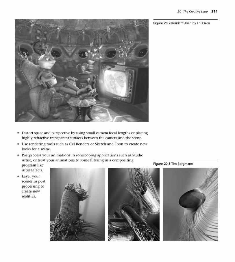
• Distort space and perspective by using small camera focal lengths or placinghighly refractive transparent surfaces between the camera and the scene.
• Use rendering tools such as Cel Renders or Sketch and Toon to create newlooks for a scene.
• Postprocess your animations in rotoscoping applications such as StudioArtist, or treat your animations to some filtering in a compositingprogram likeAfter Effects.
• Layer yourscenes in postprocessing tocreate newrealities.
20 The Creative Leap 311
Figure 20.2 Resident Alien by Eni Oken
Figure 20.3 Tim Borgmann

Walk Away from Your Computer
Whaa? You heard right. Take a day (or even better a week) and meander, un-plugged, through the rest of your world. It is there that you will find the inspira-tion, ideas, visual richness and content, which are the most important part ofwhat you will ultimately do with 3D. Turn your eyeballs on high and get yoursketchbook and #2 pencil out. Chase the dust bunnies out of the forgotten cor-ners, and search high and low for a story. Sketch everyday scenes and objects, thenbrainstorm on what would happen if they came to life in a world that knows noboundaries . . . the world of animation.
Physics Doesn’t Live Here Anymore
No boundaries. While lots of people develop some facility with the tools of 3D,not all have mentally escaped the real world. Surprise! The rules no longer apply.The laws of nature no longer demand to be obeyed and gravity has taken a va-cation. In the 3D world, objects can pass through each other, float unsupportedthrough space, or change form from solid to rubbery to gaseous in an instant.Linear perspective can be disregarded. Study Cubism, the impossible perspec-tives of Escher, and the dripping clocks of Salvador Dali for inspiration.
Challenge Reality and Play with Space
• Play with scale. Things no longer have to be the size they are in real life.Lilliputian figures can shuffle across a normal-sized coffee table.
• Rethink materials. Make a cup out of fur and ballet dancer out of glass.Animate native material into impossible mutations.
• Incorporate the pop-up book idea. Create walls in the 3D space, thenpunch holes for the camera to move through, or animate objects to popout from behind the façade to surprise the viewer.
312 Cinema 4D
Figure 20.4 Sketchbook Pages
Figure 20.5 Floating Landscape 1
Figure 20.6 Floating Landscape 2
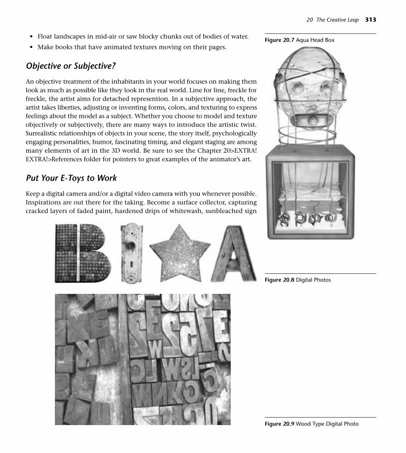
• Float landscapes in mid-air or saw blocky chunks out of bodies of water.
• Make books that have animated textures moving on their pages.
Objective or Subjective?
An objective treatment of the inhabitants in your world focuses on making themlook as much as possible like they look in the real world. Line for line, freckle forfreckle, the artist aims for detached represention. In a subjective approach, theartist takes liberties, adjusting or inventing forms, colors, and texturing to expressfeelings about the model as a subject. Whether you choose to model and textureobjectively or subjectively, there are many ways to introduce the artistic twist.Surrealistic relationships of objects in your scene, the story itself, psychologicallyengaging personalities, humor, fascinating timing, and elegant staging are amongmany elements of art in the 3D world. Be sure to see the Chapter 20>EXTRA!EXTRA!>References folder for pointers to great examples of the animator’s art.
Put Your E-Toys to Work
Keep a digital camera and/or a digital video camera with you whenever possible.Inspirations are out there for the taking. Become a surface collector, capturingcracked layers of faded paint, hardened drips of whitewash, sunbleached sign
20 The Creative Leap 313
Figure 20.7 Aqua Head Box
Figure 20.8 Digital Photos
Figure 20.9 Wood Type Digital Photo

letters, and any other details to add to your material layers. A small digital soundrecorder is also a great traveling partner for capturing and creating sounds. AProscope (available at www.apple.com) accesses unseen microscopic imageryand works on Mac or Windows.
Make Some Grunge
Get out your calendar and schedule a studio day. Gather real materials like paint,plaster, wallpaper paste, paints, glues, and sticks, and spend the day making thickand textural messes on surfaces. Scrape thick impastos and invade the surface with
314 Cinema 4D
Figure 20.10 3D Texture Found on the Backof a Truck
Figure 20.11 Target Wall Texture
Figure 20.12 Rough Paint

scratches and dents. Use paint and stains to intensify the textures. A few days laterafter the surfaces have dried (your scanner will love you for being patient), scan thesurfaces. If you have a good digital camera you won’t have to wait as long. Just lightthe surfaces from the side and shoot. Save these organic image maps in a Library.
20 The Creative Leap 315
Figure 20.13 Spray Insulation on HardwareCloth
Famous 3d Saying: “It’s All in the Details” —Anonymous
Photographing Existing Textures
• Make sure your shots are not out of focus from being too close. Use aMacro setting if you need to.
• Be sure there is plenty of illumination. Nothing degrades digital photog-raphy like a lack of light. Existing textures should be shot with side light-ing, as frontal lighting would flatten them.
• Shoot 300 dpi TIFFs whenever possible, so you’ll have adequate resolu-tion for close-up textures.
• Try to face the surface flat-on, with as little perspective as possible.(If you can’t escape the angled perspective you can use Adobe Photo-shop’s Crop tool to correct the perspective.)
Become a Scrap Rat
The current scrapbooking rage has a lot of crossover application to 3D. Go to ascrapbooking store and you’ll be inspired. The collage mentality leads to richtextures and backgrounds for 3D. In a shoe box or filing cabinet, collect treas-ures—tags and torn papers, strings and ribbons, handwriting and doodles, sta-tionery items, Want to create textures that have a genuine look? Stain papers inteabags. Think about how scrapbooking activities like punching decorative
holes in paper, em-bossing, using dec-orative grommets,stitching, or staples,and dusting withglitters and metalicscould translate into3D forms and sur-faces.
Figure 20.14 Scrap-book Examples
Figure 20.15 Tags in 3D

Create Libraries of Digital Details
The more collections of cool things you have already made, the faster your work-flow will go.
Mechanical parts, splines, symbols, patterns, confetti, interesting small ob-jects, light fixtures, architectural details, character accessories, face parts, color-ful game pieces, letters, decorative 3D forms, color palettes, fonts, and materialsin easily accessed and well organized Libraries will speed up your work and en-able you to quickly add more interest to scenes.
On the DVD: See examples of these in GOODIES>LIBRARIES.
316 Cinema 4D
Figure 20.16 Charm Library
The Holistic Artist
The best digital artists often make nonvirtual art too and find ways to integerateor cycle the nondigital into the digital (and vice versa). Bring that video, sculp-ture, painting, or drawing into your 3D world and use it as a background or wrap
Figure 20.17 Flower Swag
Figure 20.18 Green Box Figure 20.19 Baby Squares Figure 20.20 Wall Piece 1

it around a model. Turning the process around, use a printout of your 3D sceneas inspiration for a large painting or sculpture.
Optimize Your Creative Time
Everyone has times when their mental wheels just won’t stop spinning. For some,it’s when they first wake up. Once you’ve identified your best creative time, don’tsit down at the computer and get bogged down in process. Instead, crash in a com-fortable place with your sketchbook and pencil. (Sometimes colored pencils, gelpens, or watercolors can add to the creative flow.) Let the personal brainstorm-ing session happen away from the computer.
Become An Art Historian
On your way to finding your own style, it’s helpful to study other artists, illus-trators, filmmakers, and architects of the present and past. In analyzing the workof others, lessons about design and storytelling begin to sink in almost subcon-sciously. It’s fun to add depth and interest to your work with historical references.You may find yourself developing affinities for stylistic flavors from the past thatmay weave themselves into the tapestry of your own style.
Cultivate Efficient Work Habits
• Back up animation projects often and in several different locations andvolumes. Things happen.
• Create a structured organizational system for everything you use and createin 3D. (See Chapter 17.) You should be able to go right to Models, Sounds,Image Maps, Splines, Resources, Fonts, and all the other bits and pieces.
• Use logical titles that will be easy to find in a systemwide search later (for ex-ample, when you are trying to find a model rather than make it from scratchall over again). Titles like Number Two are as good as lost in space forever.
• Keep a Calendar and Task list to keep projects on track.
• Learn where to find references. The name of an object typed in GoogleImage will bring up thousands of visual references. These images are copy-right protected, but you can check details like the colors of a parrot or thenumber of legs on a squid.
Storyboards, Thought Charts, Animatics
A storyboard is a collection of still sketches that show key stages in the devel-opment of a story. Ideally, the drawings communicate the feeling of the moment
20 The Creative Leap 317
Figure 20.21 Wall Piece 2

without being too labored over or sacred. The more time that is spent on a sto-ryboard, the less willing one might be to rip it up and replace it with a betteridea. Storyboards can be rather thumbnail in size, but in studios they are oftenletter size (8 1/2”x 11”).
Thought Charts are verbal plans that state what each character is thinking inkey frames. These are a valuable aid in creating characters that appear to be aliveand acting out their own desires, rather than being puppeteered by an animator.
An Animatic is a rough approximation of the finished animation. It can be-gin as a slideshow of the storyboards, but can include sections of rough or closeto finished animation as the process unfolds. The animatic is structured on theactual timeline of the finished piece, so the actual music and sound may be inthe background.
Most animators keep some sort of Archive, that holds the collected notes,storyboards, and resource files for a single project and tells the story of the proj-ect’s development. Be sure to write down important settings in case somethinghas to be recreated.
318 Cinema 4D
Figure 20.22 Storyboards
3D as a Day Job
Every aspiring artist has surely been encouraged away from art and toward more“responsible” fields by a parent, relative, or friend who sees art and animationas immature play rather than legitimate work. Because the animation field is in-herently fun and requires playful thought, it may appear to lack the seriousness
of other grown-up careers. In fact, the vocation requires long hours, hardwork, dedication, and mountains of academic study. If you find that
you are so passionate about working in 3D that you can’t wait to getup in the morning and begin again, there’s a good chance it could be
a viable career for you.
On the DVD: As your 3D skills grow, you’ll be designing in-creasingly complex worlds. Without some basic under-
standing of color theory and the principles of design,you’ll be creating with a limited set of tools. See Chap-ter 20>EXTRA!EXTRA!>References for resources tojump-start for your creativity and design skills. Themore you learn about traditional art, film, and de-sign, the more exciting and cohesive your workwill be.
Figure 20.23 Cards

319
Appendix
Figure A.1
I f you are new to CINEMA 4D, this reference section covers what you need toknow now about general use of the application. As always, see the manual fordetails and further explanatory text. The documentation disk that shipped
with your copy of C4D has the manual in PDF form. Install it if you want to havethe manual always available under the Help menu.
Basics of the C4D Interface
Fire up your engines! Start CINEMA 4D by clicking the C4D icon in the dock orthe original application icon. You can also drag a C4D file onto either icon. Al-though double-clicking a C4D file will usually open the application, there aretimes when that’s not the best way. Quit with File>Quit or Command-Q, savingat that point if you need to. However, the best saving habit is to save immedi-ately upon starting a project and update with a quick Command-S every time youstop to think. An important twist on saving is when you have any texture thatyou have imported (apart from the shaders inside CINEMA 4D, for example aphotographic image map you imported). It is necessary to use Save Project if youwant the textures to stay with the project so that it will render properly. (SaveProject creates a nice folder for you and tucks everything inside.)
In the default layout, there is a main menu across the top, one down the leftside of the main window, and another smaller menu at the top of each ViewPanel, sometimes called the Editor window (the one where you see the objects).
A new view panel can be added any time by choosing Window>New View Panelfrom the top menu. Each View window has a unique menu, so it can have sep-arate settings for angle of view and display style. Go to View>Panels on at the topof each view for a variety of pre-designed panel layouts. If you want to view yourscene from a different angle, or from perspective, top, side and front simultaneouslyuse these key shortcuts to switch from view to view. (Or choose them from theView menu in each View.)
• F1 View 1 Perspective
• F2 View 2 Top
• F3 View 3 Right Side
• F4 View 4 Front
• F5 All Views
To change the way objects are drawn in a view, choose Display from thatView’s menu. Gouraud shading roughly previews the general effect textures andlighting, but Wireframe or Isoparm displays are much faster and may be all youneed when modeling. When working with complex motion in animation, boxdisplay may be necessary. Wireframe and Isoparm displays let you see into orthrough the object, making it easier to select buried points. When modeling, itcan be helpful to make a new View Window and set one window to Gouraud dis-play (so you can clearly see the surface), but change the display of the other win-dow to Wireframe or Isoparm (so you can easily see and select points on themesh). You can also assign a specific display style to just one object in a sceneby assigning a Display Tag (Right-click on the object, choose NewTag>Display Tag,click Use Display Mode, and choose the display style from the pull-down menu.)
The Manager Windows are specialized work areas that house the controls forthe major processes in CINEMA 4D. Most manager windows have a menu spe-cific to the work of that window. Be aware that for shortcuts (such as Command-A) to work in a Manager window, it must be the active one. It’s a good habit to
click on an empty area of a window to acti-vate it before working.
Changes in Version 8 from Previous Versions
Former CINEMA 4DXL users should note thatit is no longer necessary to double click theEdit Object Icon to open a window for editinga new object. The information is now auto-matically available in the Attributes Manager,available by default underneath the ObjectsManager. Objects can now be Shift-selected inthe Editor or the Objects Manager, allowing formultiple selections to which settings or trans-
320 CINEMA 4D
Figure A.2 View Menu, View Window and Manager Windows

formations can be applied simultaneously. For example, ten separate lights couldbe reduced in brightness at the same time by Shift-selecting (or dragging a rectan-gular marquis over) the lights and turning down the brightness of one. F-curves pro-vide a more streamlined and powerful way to control animation keys. See theCINEMA 4D manual and the Addendum PDFs for a complete list of changes in ver-sions 8 through 8.5.
The World Grid and 3D World Geography
In C4D, Y is up and is the vertical axis of the 3D world, or the height. X is thehorizontal axis or width, and Z goes away from you into space representing thedepth of the space. It will also help to memorize the colors of the axes in CIN-EMA 4D. You may get turned around at times and not be able to see the labels,and the colors may be your only signpost.
Successfully navigating the 3D world requires familiarity with the geogra-phy of the 3D space.
The world grid is a default construction plane, a subdivided grid that helpsyou get your bearings and imparts a sense of where you are placing objects. Thegreen, red and blue arrows in the world grid represent the world axes. The po-sition of any object axis or even any single point in the world can be defined byits coordinates, or numeric values on each world axis.
The origin of the world is where the X, Y and Z axes coincide; the locationwith coordinates of 0,0,0. The diagram in Figure A.3 shows the direction of pos-itive and negative values for each axis. It may seem strange that negative Z (–Z)comes to the front and positive Z (+Z) goes to the back, but that’s the way it is!
Appendix 321
Figure A.3 The World Grid and World Axes
In the modeling process, it may help to imagine the invisible planes definedby any two axes. For instance, the world’s default construction plane lies on theXZ Plane.
There are several ways you can manipulate the camera through which youare viewing the 3D space. One way is to use these hotkeys to navigate the view.
1 + Mousedrag Moves the camera from side to sideor top to bottom
2 + Mousedrag Moves the camera in and out
Figure A.4 XY, ZY and XZ Planes
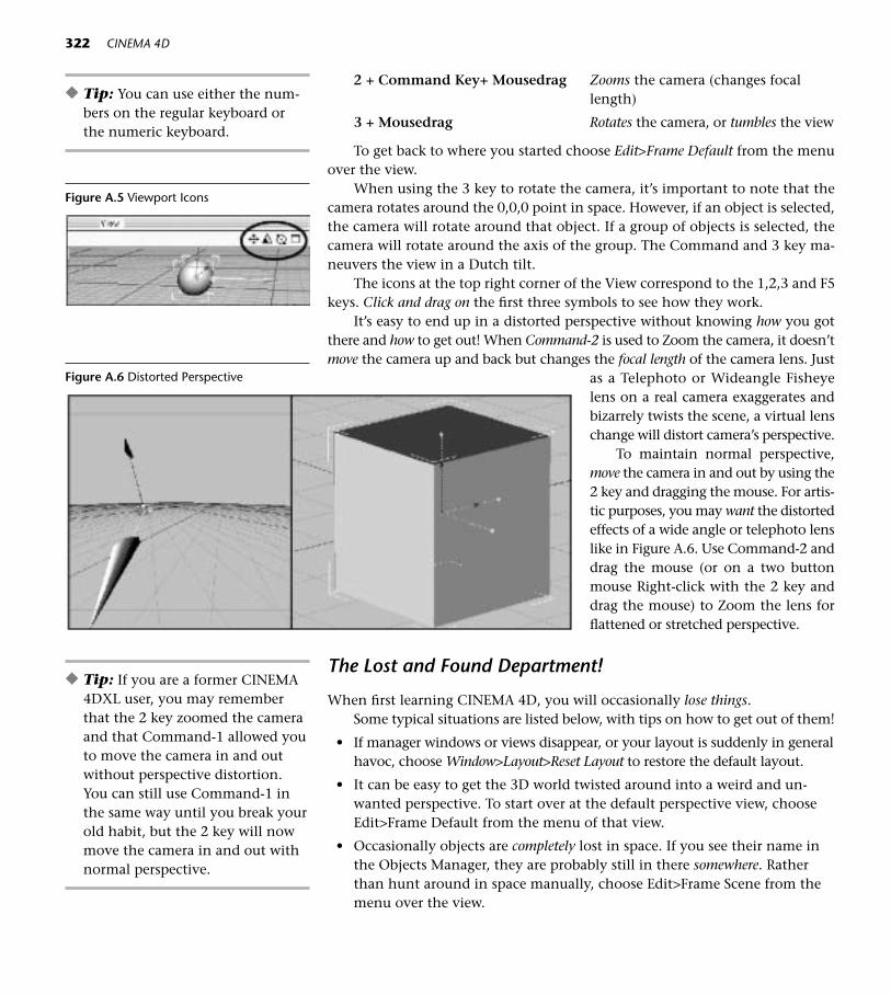
2 + Command Key+ Mousedrag Zooms the camera (changes focallength)
3 + Mousedrag Rotates the camera, or tumbles the view
To get back to where you started choose Edit>Frame Default from the menuover the view.
When using the 3 key to rotate the camera, it’s important to note that thecamera rotates around the 0,0,0 point in space. However, if an object is selected,the camera will rotate around that object. If a group of objects is selected, thecamera will rotate around the axis of the group. The Command and 3 key ma-neuvers the view in a Dutch tilt.
The icons at the top right corner of the View correspond to the 1,2,3 and F5keys. Click and drag on the first three symbols to see how they work.
It’s easy to end up in a distorted perspective without knowing how you gotthere and how to get out! When Command-2 is used to Zoom the camera, it doesn’tmove the camera up and back but changes the focal length of the camera lens. Just
as a Telephoto or Wideangle Fisheyelens on a real camera exaggerates andbizarrely twists the scene, a virtual lenschange will distort camera’s perspective.
To maintain normal perspective,move the camera in and out by using the2 key and dragging the mouse. For artis-tic purposes, you may want the distortedeffects of a wide angle or telephoto lenslike in Figure A.6. Use Command-2 anddrag the mouse (or on a two buttonmouse Right-click with the 2 key anddrag the mouse) to Zoom the lens forflattened or stretched perspective.
The Lost and Found Department!
When first learning CINEMA 4D, you will occasionally lose things. Some typical situations are listed below, with tips on how to get out of them!
• If manager windows or views disappear, or your layout is suddenly in generalhavoc, choose Window>Layout>Reset Layout to restore the default layout.
• It can be easy to get the 3D world twisted around into a weird and un-wanted perspective. To start over at the default perspective view, chooseEdit>Frame Default from the menu of that view.
• Occasionally objects are completely lost in space. If you see their name inthe Objects Manager, they are probably still in there somewhere. Ratherthan hunt around in space manually, choose Edit>Frame Scene from themenu over the view.
322 CINEMA 4D
Figure A.5 Viewport Icons
Figure A.6 Distorted Perspective
◆ Tip: You can use either the num-bers on the regular keyboard orthe numeric keyboard.
◆ Tip: If you are a former CINEMA4DXL user, you may rememberthat the 2 key zoomed the cameraand that Command-1 allowed youto move the camera in and outwithout perspective distortion.You can still use Command-1 inthe same way until you break yourold habit, but the 2 key will nowmove the camera in and out withnormal perspective.

The number of “undo levels” can be set in preferences. In C4D, Command-Zsteps back as many levels as you have set, and the Redo command Command-Ysteps forward. The default level is 10.
Working with Objects
Each Object created in C4D is “born” in the center of the 3D world where theX, Y and Z-axes coincide at coordinates 0, 0, and 0. Each object has its own setof axes, so if the object is tilted those axes are no longer oriented in space as whenthey were born, and no longer match the world axes in orientation.
To select an object for editing or transforming, you can click on the objectitself in the Editor window. A better habit is to click on the name of the object inthe Objects Manager. All the transform tools (Move, Scale and Rotate) can be usedto select objects or their inner elements in the Editor window. For more complexselections, the selection tools in the top menu can be used.
The Objects Manager
Welcome to Inventory Central! CINEMA 4D’s Objects Manager is the bin whereall the objects in your 3D world are listed by name. More importantly, objectsare listed in a meaningful diagram called a Hierarchy that visually communicatesthe relationship of one object to another. It will be clear to you when objects arein Groups or Parent/Child relationships.
In the Objects Manager, object names are critically important for recognition,selection and organization. Taking the time to rename generic elements like splinesand primitives is a necessary habit that will pay big dividends later when you at-tempt to manage large projects.
“Pool Ball 8,” “Mars,” and “Eyeball” will provide more information than“Sphere,” “Sphere,” and “Sphere.”
Take a look at the dots and checks in the column to the right of the objectnames. When clicked twice to a red state, the top dot turns off the visibility of
Appendix 323
Figure A.7 Selection Tools
Figure A.8 A Hierarchy in the ObjectsManager
an object in the Editor window. The bottom dot does the same thing for visi-bility in final rendering. The visibility will be that of the object’s parent if thedots are gray. A green dot means the object will be visible even if its parent is in-visible. The check marks activate and deactivate deformers and generators. (De-formers and Generators are tools you will use later to modify the shape and stateof objects or primitives.)
Tags (including the tags for textures) have their own icons in the third col-umn to the right of the object name. You can also drag and drop these from oneobject to another in the Objects Manager. To access a contextual menu of tagsin the Objects Manager, Command-click (Or Right Mouse button) on the objectand choose the tag you want from the New Tag sidecar menu.
The Attributes Manager
The Attributes Manager is where you will find all the editable characteristics aboutan object currently selected in the Objects Manager. It is here where you will goto enter or modify all information about an object. You can even set animationkey frames in the Attributes Manager by Command-clicking the title word or let-ters next to a value and dragging over to Animation>Add Keyframe.
324 CINEMA 4D
Figure A.9 The Attributes Manager
The Model and Object Tool
First let’s talk about the Model tool in relation to the Points, Edges, Polygons, Axisand Texture tools. Use the Model tool when you want the action of the Move, Scaleor Rotate tools to apply to the Object as a whole. However, if you want to get underthe hood to edit elements that make up the object, switch to the Points, Edges, Poly-gons, Axis or Texture tool to use the Move, Scale or Rotate tools on those respectiveelements. You’ll have to make the object editable (just type the “C” key!) beforebeing able to access them!
Figure A.10 L>R, Model, Points, Edge,Polygons, Object Axis, Texture and MakeEditable Tools
Figure A.11 Model Tool, Object Tool
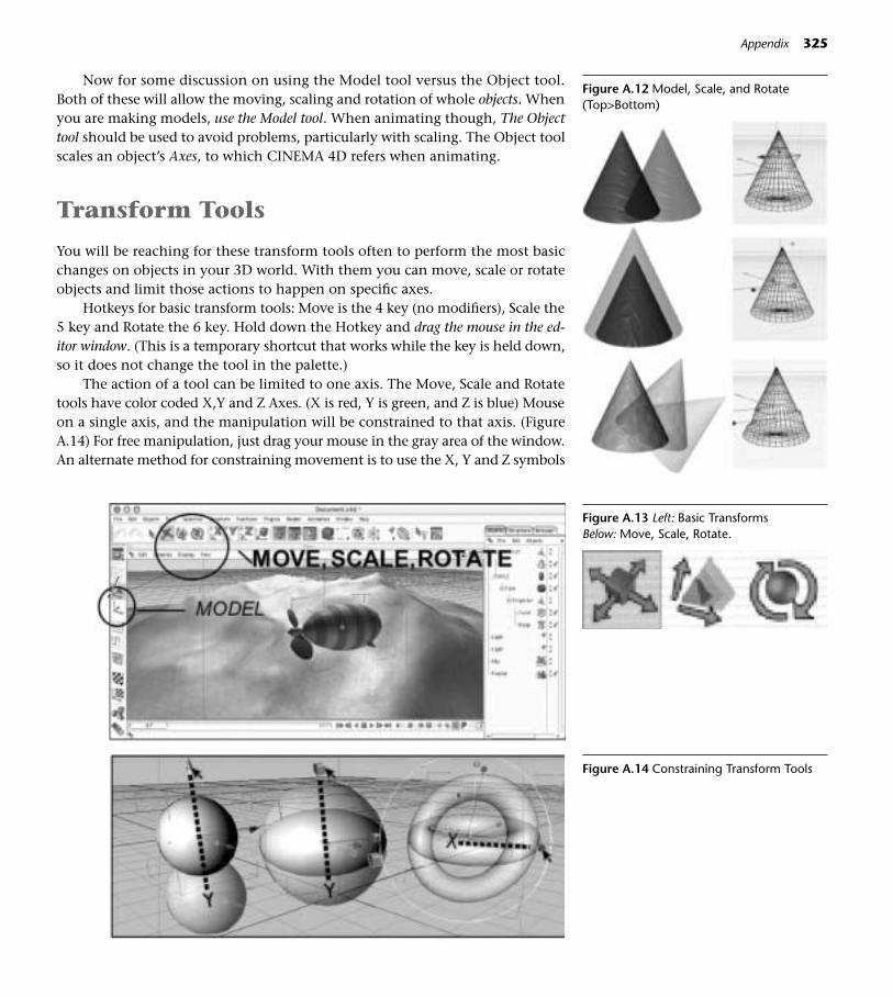
Now for some discussion on using the Model tool versus the Object tool.Both of these will allow the moving, scaling and rotation of whole objects. Whenyou are making models, use the Model tool. When animating though, The Objecttool should be used to avoid problems, particularly with scaling. The Object toolscales an object’s Axes, to which CINEMA 4D refers when animating.
Transform Tools
You will be reaching for these transform tools often to perform the most basicchanges on objects in your 3D world. With them you can move, scale or rotateobjects and limit those actions to happen on specific axes.
Hotkeys for basic transform tools: Move is the 4 key (no modifiers), Scale the5 key and Rotate the 6 key. Hold down the Hotkey and drag the mouse in the ed-itor window. (This is a temporary shortcut that works while the key is held down,so it does not change the tool in the palette.)
The action of a tool can be limited to one axis. The Move, Scale and Rotatetools have color coded X,Y and Z Axes. (X is red, Y is green, and Z is blue) Mouseon a single axis, and the manipulation will be constrained to that axis. (FigureA.14) For free manipulation, just drag your mouse in the gray area of the window.An alternate method for constraining movement is to use the X, Y and Z symbols
Appendix 325
Figure A.12 Model, Scale, and Rotate(Top>Bottom)
Figure A.13 Left: Basic TransformsBelow: Move, Scale, Rotate.
Figure A.14 Constraining Transform Tools

326 CINEMA 4D
on the top palette. If one of these islocked (no line around it), the object willnot be able to move on that axis. If youwant to move the object only alongone axis, then the symbol for that axisshould unlocked. (It should have a linearound it!)
Each object has its own system ofaxes placed by default in the center ofthe object when it is created. Theseaxes are used as an orientation pointby the Move, Scale and Rotate tools, and the coordinates of an object’s axis de-fine the single point on the object referred to in matters of positioning and
Figure A.15 Object Axis Figure A.16 Make Editable, Model andObject Axis Tools
Figure A.17 Object Coordinates System Icon
Figure A.18 World Coor-dinates System Icon
movement. You will often need to move the object’s axis either within or com-pletely outside the object using the Object Axis Tool. For example, a planet ro-tating around the sun would have its axis, the point of rotation, at the center ofthe sun.
The object’s axis is independent of the world axes, and you can decide whichset of axes to use. Click the Object Axis icon to switch to the World axes.
The Coordinates Manager is where numeric values for position, size, scale, androtation may be input. In addition to entering typed values, you can quicklychange the values by dragging on the small black arrows by each input box (dragupward for larger increments and downward for smaller ones), or by single-click-ing the arrows with the mouse to nudge tiny changes. If you have a wheel mouseyou can spin the values. Don’t confuse this separate manager with the Coordi-nates panel in the Attributes Manager, where you can Command- or right-clickon the names of values and set key frames from the Contextual menu.
Rotation in the Coordinates Manager is entered in plus or minus values for Hor Heading, P or Pitch, and B or Bank. Heading rotates around the Y axis, Pitcharound the X axis and Bank around the Z axis. Visualizing those terms in relationto an airplane may help you get your bearings.
These are the basic working elements in CINEMA 4D:
• Points are also called control points or vertices, defined by their positionin the X,Y,Z space.
• Splines are lines in space, series of points connected by lines that can be
straight or curved. Splines are invisible in rendering.
• Spline Primitives are splines of various shapes available in the palette.
Figure A.19 The Coordinates Manager
Figure A.20 HPB System
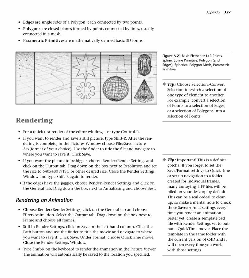
Appendix 327
• Edges are single sides of a Polygon, each connected by two points.
• Polygons are closed planes formed by points connected by lines, usuallyconnected in a mesh.
• Parametric Primitives are mathematically defined basic 3D forms.
Rendering
• For a quick test render of the editor window, just type Control-R.
• If you want to render and save a still picture, type Shift-R. After the ren-dering is complete, in the Pictures Window choose File>Save PictureAs>(format of your choice). Use the finder to title the file and navigate towhere you want to save it. Click Save.
• If you want the picture to be bigger, choose Render>Render Settings andclick on the Output tab. Drag down on the box next to Resolution and setthe size to 640x480 NTSC or other desired size. Close the Render SettingsWindow and type Shift-R again to render.
• If the edges have the jaggies, choose Render>Render Settings and click onthe General tab. Drag down the box next to Antialiasing and choose Best.
Rendering an Animation
• Choose Render>Render Settings, click on the General tab and chooseFilter>Animation. Select the Output tab. Drag down on the box next toFrame and choose all frames.
• Still in Render Settings, click on Save in the left-hand column. Click thePath button and use the finder to title the movie and navigate to whereyou want to save it. Click Save. Under Format, choose QuickTime movie.Close the Render Settings Window.
• Type Shift-R on the keyboard to render the animation in the Picture Viewer.The animation will automatically be saved to the location you specified.
Figure A.21 Basic Elements: L>R Points,Spline, Spline Primitive, Polygon (andEdges), Spherical Polygon Mesh, ParametricPrimitive
◆ Tip: Choose Selection>ConvertSelection to switch a selection ofone type of element to another.For example, convert a selection of Points to a selection of Edges, or a selection of Polygons into aselection of Points.
◆ Tip: Important! This is a definitegotcha! If you forget to set theSave/Format settings to QuickTimeor set up navigation to a foldercreated for Individual frames,many annoying TIFF files will bepiled on your desktop by default.This can be a real ordeal to cleanup, so make a mental note to checkthose Save>Format settings everytime you render an animation.Better yet, create a Template.c4dfile with Render Settings set to out-put a QuickTime movie. Place thetemplate in the same folder withthe current version of C4D and itwill open every time you workwith those settings.
Previewing an Animation
From the top menu, select Render>Make Preview. In the input box, click yourchoices for the kind of preview you want. The progress box at the bottom left ofthe main window will show you the rendering progress, and then a QuickTimewindow will open. Click the Play button. Choose File>Save if you want to savethe QuickTime preview movie.
Chose Preferences>Edit>Viewport to turn on Render Safe (the borders ofyour final rendering determined by the format choice in your render settings),Action Safe or Title Safe (for TV output) guidelines.
Customization
You can place any elements of the C4D interface anywhere you wish, and thensave your redesigned workspace as a custom layout (Window>Layout>Save Lay-out As), and place the file inside the Library>Layout folder which resides in thecurrent CINEMA 4D folder. It will then be accessible in the Layout icon at the topof the Left Palette.
If you want to float a window and be able to move it freely around the work-space, click the pushpin in the upper left corner of any window and drag over tochoose Undock. If you click the red close button on the window, it will disappearfrom the interface. To bring it back, choose the name of the window from theWindow menu.
If you want to make a Manager window share a space with another window,and reside as a tab in the same tab bar, drag the window’s pushpin and drop it onthe pushpin of the target window. Dragging a window’s pushpin against the edgeof another window will result in a new docking position. To change the height orwidth of a window, mouse on its border and drag with the double-sided cursor.
To restore the layout to the original layout, choose Window>Layout>ResetLayout.
Click on the top icon of the left-hand tools palette to choose a layout ap-propriate for the task at hand. CINEMA 4D has several already built in that areset up for specific tasks, like using MOCCA or BodyPaint 3D.
Right-click on a Palette to access a contextual menu for custom editing.Choose Edit Palettes and you will be able to drag and drop icons from onepalette to another, or delete palettes.
Choose Window>Layout>Command Manager and you’ll see a complete listof all CINEMA 4D’s commands. Select the command for which you want to as-sign a key combination. Click in the Assign Text box and type the short-cut. Clickthe green check to the right of the text box and the new shortcut will appear inthe Current box above. (You’ll get a message if the key combination you requestedis already in use.) As an example of how shortcuts can make your life easier, long-time Photoshop users might capitalize on their lifetime Command-D habit by as-signing it to Deselect All.
328 CINEMA 4D
Figure A.22 Layout Icon
To restore CINEMA 4D to its original factory settings, throw away the CIN-EMA 4D.prf file in the current C4D Prefs folder. Don’t be afraid! The next time youuse CINEMA 4D, a clean prefs file will be created automatically. You can explorethe deeper meaning of the many preferences settings in your manual. Preferencesettings will stay in place from file to file, until you change them or restore the orig-inal settings. One note: If you plan to use a Graphics Tablet (which is a must haveif you plan to use BodyPaint 3D), better head right into Preferences and check theGraphics Tablet checkbox, or you’ll see some strange cursor behavior.
Project Settings (Top Menu>Edit>Project Settings) apply only to the currentscene. Here you can set a frame rate appropriate for your output, enter the firstframe of the animation in the Minimum box and the last frame in the Maxi-mum box.
If you are working on a Mac, buy a two-button wheel mouse if at all possible.Right-clicking will bring up contextual menus and streamline your workflowgreatly! If you stick with the regular Mac mouse, holding down the Command(Apple) key does the same as right-button mousing. If your mouse has a wheel, useit to scroll sliders, enter values in numerical input boxes, and move in and out ofthe editor window.
CINEMA 4D plays cross-platform very nicely. With just the usual differenceslisted below, there is little difference between the Mac and PC versions of CIN-EMA 4D.
MAC PC
Command Control
Opt Alt
Command-click Right-click
The Selection Filter allows you to turn the selectibility of certain subcategoriesof objects on and off. This applies to the Editor window (and not the ObjectsManager where all objects can always be selected). When scenes get very densewith objects, you can use this list to isolate the type of objects you’re working on.Just Control-click on one object and all others will be disabled, or uncheck theobjects you don’t want to be selectable. You can also Shift-select objects andchoose Create Selection Object from the Selection Filter list, creating a selectionobject in the Objects Manager. Later, if you click Restore in the Attributes Man-ager, all these objects will select at once for easy multiple editing.
Remember that in R8 you can Shift-select multiple objects (in either the EditorWindow or the Objects Manager) and mass edit parameters, but there would betimes when having a complex group of objects already saved would make thingsmuch easier.
The Display Filter works the same way, but determines which sets of objectswill be visible in the editor window. You’ll still see the axes of objects which havebeen made invisible. To return the objects to the view, just check the checkboxagain.
Appendix 329
Figure A.23 Selection Filter forEditor Selection
Figure A.24 Display Filter
◆ Tip: You can access a glossary ofterms pertinent to CINEMA 4D athttp://www.maxoncomputer.com.

AnimationAnimation,
PipelineTimelineAdd keyframeToolbarEnd of animationAnimation layout
LayoutWindows commandsMultiple button mouse (three
button mouse, two but-ton mouse)
Primitive (s)ParametricParametersPointsPolygonsEdgesAxesMake EditableEditor WindowHierarchyManagers,
AttributesCoordinatesMaterialsObjectsStructure
Renaming objectsObject propertiesOrientationToolbarsRadiusModel toolMove toolScale toolRotate ToolObject toolChildParent
Index
GroupDependencyArrayFrame SceneNull ObjectBhodiNUTBhodiNUT volumeSLASmells Like AlmondsDiffuseColor PickerSpecularReflectionParametersGalaxy BallMaterial
ThumbnailManagerEditorCopying aNew
ColorPage PaneParameter
LuminanceLocksTransformationsCoordinates panelX,Y, and ZR.H, R.P, R.BHeading (See Rotation)Pitch (See Rotation)Bank (See Rotation)Rotation
HeadingPitchBank
Add keyframeEnd of animationBarometer ConeDisplayCopyS.X, S.Y, and S.ZOrthographicTransparencyRefractionBanjiRoughnessBumpTest renderingColor dropsFunctions menuDuplicateGenerate instancesInstancesPlacing materialsTexture tagRecord button
PositionRotationScaleFrameCurrent time sliderViewBubbling teardropCapsConeSphereCubeTorusFillet segmentsMaterialRGB slidersVolume tabBump functionTurbulencePlay buttonPreview renderingMake previewFull RenderQuickTime movieDNA SpinnerSymmetry objectMirror planeFrame active objectBrowserFile>import fileStarlight lanternParametric handleX,Y,Z LockTexture panelAlpha channelVolumetric lightsCosmic receiverCapsuleTube LightTransferRandomizeEditor cameraTrackZoomFocal lengthView hotkeysPandora’s BoxSubdivisionSliceAll viewsView 1View 2View 3View 4Easy and BreezyAtom ArrayPlatonicIcosaBhodiNUT TilesGyro
SegmentsNukeiBanziVisibilityCameraF-CurveFrame allFrame selectedFrame active objectGraphKeysColor BarrelIsoparmWireframeImage MapGouraudCylinderMaking primitives editablepolygonal surfacequadrilateral triangular verticesAdjoining polygonsMeshPoints toolEdge toolPolygons toolDiscHyperNURBSGeneratorCageProjectionRectangle selection toolActive Tool tabOnly select visible elementsRectangular selectionLive Selection toolExtrude Top viewSide ViewFront ViewPerspective viewPreserve groupsSet SelectionSelection setsDeselectSelection tagMatrix extrudeExtrude InnerUnfold AllMade editableObject axisObject axis toolStitch two separate surfacesBridgeWeldConnectPoly countObject Information
330

Scene InformationKnife toolSubdivisionsPhong tagMagnet toolTumbling the viewDutch tiltOffsetUVW ProjectionSpline (s)TangentBezierHard interpolationSoft interpolationSegmentsClosed splineBezier splineBezier spline toolSpline primitivesCreate OutlineSpline libraryImport splinesNURBSNonuniform Rational B-SplinesUnfold allExtrude NURBSLathe NURBSLoft NURBSSweep NURBSBezier NURBSWorld coordinate systemHelix settingsTangent handlesMirrorUndoRedoUndo viewRedo viewGrowthReverse sequenceAdd PointsSegmentsOverriding Hyper NURBS influ-
enceDisable Backface CullingConverting NURBS objects
back to polygonalmeshes
Current state to objectDeformersTwist deformationBend deformationBulge deformerExplosion deformationShatter deformationWind deformerShear deformerBoolean operationsArrange function
Metaball objectTexturesParametersParameter paneShadersProcedural shader2D shaders3D shadersChannelImage buttonSpecular highlightBhodiNUT fusionTexture errorTex folderAlphaAlpha channelPlacing and adjusting materialsTypes of mappingTexture>fit to objectSelection boxTag propertiesCaps and roundingDiffusion channelCopy channelPaste channelSpecular colorBhodiNUT volumeBump functionBatch renderingMovie data boxUsing a movie as a materialTimeline windowAnimation layoutKey propertiesExpressionsXpressoNodeLighting setupDifferent types of lightsThree point lighting systemMain lightFill LightMain to fill ratiosBackground lightTypes of light and their settingsChoosing appropriate lightingTarget lightTarget tagGobosVisible lightsEditing multiple lightsAlign to splineVector selectionWorking with custom tangentsHold keyframesEase outsEase insAutomatic modeManual mode
Animation principlesSquash and stretchTime curvesSequence propertiesPLA trackPoint level animationEnable PLARecord buttonAutokeyframing buttonAdding soundPlay sound buttonAlign to spline tagVibrate expressionMove down sequenceSubdivideNew view panelReset LayoutDisconnectSplitHide unselectedUnhide allSet valuePosemixerCharacter building methodsForward kinematics Inverse kinematicsIK setupIK toolEffectorAnchor TagGoal objectSoft IKBones
Add bone deformationFix bonesReset bonesRange LimitVertex WeightsClaude Bonet toolBone toolNull BoneRoot BoneAdd/update null boneAdd bone
MOCCASoft IKMOCCASoft IK tagStop tagSet chain rest positionSet chain rest rotationAdd root goalAdd tip goalAdd UpVectorMOCCA PaletteBone Mirror toolAuto Find Center Box
Posemixer handMultiple Versions and States of
CharactersAnimating FKAnimating Soft IKSet driven keyPosemixer animationFilm planeTarget camerasCamera on a spline pathComplex camera movementDepth of fieldSwitching camerasRender active viewRender in picture viewerRender settingsAntialiasingRender as editorRender settingsFormatEffects tabObject motion blurScene motion blurCel renderingMulti-pass renderingRendering a QuickTime VRAdvanced renderingSavingStarting QuitingWorking with viewsWorking with reference imagesDisplay optionsManager windowsWorld gridNavigating the 3D worldTransform toolsRelocating an object’s axisThe HPB systemRendering an animation Previewing an animation, (see
Preview)Render safeTitle safeCustomizing layoutsDocking and undocking win-
dowsMultiple layoutsCustomizing palettesCustomizing command short-
cutsPreferencesProject settingsPCSelection filterDisplay filterModulesPlugins
Installing Mesh surgeryJenna
Index 331

LocoDiToolsSniper ProSurface PainterShave and a HaircutSketch and ToonSpeedDisplayMultiple Spline AttachHelixOnyxTreeOzoneXfrogAdd-the-SeaBonderlandLittle Cup of MoccaHair DepartmentFizzStitch & SewTime Frequency
Plugin CaféXpresso editorXpresso
PortWireInput squareNode
Structure, (See manager)Bezier Spline toolMergeInterior environmentArchitectural detailSkiesSky objectBackgroundsForegroundsFloorsBackdropsCycloramasTreesGrassWaterWeatherParticlesPixiedustSmoke and fireSmoke emittersPyroclusterSoundBP Paint layoutBodyPaint 3D
Set-up wizardBrush presetsWallpapersRaybrush render ViewColor paletteBlendingMasksDraw text toolProjection painting
MultibrushingDraw text toolDraw Polygon shape
Adobe IllustratorMacromedia FreehandAdobe PhotoshopPixologic ZbrushSynthetik Studio ArtistCorel PainterGaragebandSoundtrackApple Final Cut ProQuickTimeFlashExAdobe ImagereadyIviewText splinesAdd Text splineMaterials on textText on Illustrator PathsLoad ObjectAnimated type effectsMotion graphicsCompositingAdobe After EffectsFrame selected elementsWrap deformerAfter Effects pluginMulti-Pass layers in After Ef-
fectsCamera fly-throughsDigital cameraProscopePhotographing Existing Tex-
turesWork habitsStoryboardsThought chartsAnimaticEmitterParticle Emitter, (See Emitter)
I didn’t know how to handlethese below. I think theyshould go in the index, butthey would not be “search-able” with your software, (Idon’t think, but then again Idon’t really know how itworks.) If the search wordshave to be exact, the textcould not be extracted tocommunicate as well as thesephrases. I tried to give an ideaof where they are related tofigures they were closest to.
These would only occur inone place, so if you did a
search for one key word, itwould bring up a lot of inap-propriate references:
For example:Keyframing Light Visibility
Each of these words alonewould bring up a number ofunrelated references.
Attributes Manager, Coordi-nates Chapter 01Above Figure 1.26
X,Y and Z axes Chapter 01Sidebar above Figure 1.2
Enabling types of animation Chapter 01, Figure 1.33
Setting keyframes Adding points to splines
Chapter 02, Fig 2.62Connecting splines
Chapter 03, Fig 3.7Deleting animation, Remov-
ing animation Chapter 04 Before Figure4.7
Excluding objects from lights Chapter 06 After Fig 6.3
Keyframing light visibility Chapter 06 Before Fig.6.12
Timeline, automatic and man-ual modes Chapter 07after Fig. 7.7
Adjusting F-Curves with tan-gent handles Chapter07 Right before Fig. 7.8
Adjusting timeline and f-curveviews Chapter 07 Be-fore Fig.7.10
Copying keys in the timelineChapter 07 Fig.7.14
Copying objects in the objectsmanager Chapter 01(right now above Fig.1.36 but I think Copying(needs a sidebar whichI will add in Chapter 1)
Copying materials in the ma-terials manager (wouldgo in the same sidebar.)
Copying objects in the ob-jects manager (Chapter1 after Figure 1.35)
Setting up a view through acamera Chapter 11 afterFig 11.3
Camera, interactive adjust-
ment Chapter 11 Fig.11.6
Camera, following moving ob-ject Chapter 11 afterFig.11.12
Camera, inside a null object Camera, circling subject Camera, move versus zoom Pasting images into BodyPaint
Chapter 16 above fig16.20
Alpha channel, renderingChapter 19 After fig 19.3
332 CINEMA 4D

Index 333

334 CINEMA 4D

Index 335

336 CINEMA 4D

Index 337

This Page Intentionally Left Blank

This Page Intentionally Left Blank

Guide to the DVD
The gestalt of this book package is much more than thetext, so remember to spend time with the DVD. It’s literallyloaded with instruction presented in alternate forms. Re-member to browse through these folders as you read eachchapter for a wealth of extra learning experiences.
Chapter Folders
With the exception of the Goodies Folder, which containscollections of models, materials, splines, and other freebiesfor overall use, materials related to specific chapters are ina folder named by the chapter number. For organizationalpurposes, the folder structure is identical from chapter tochapter, so don’t be alarmed at the occasional empty folder.You may want to use the folders later as you generate yourown examples. The structure within each chapter foldergoes like this:
C4D Files: In this folder you’ll find CINEMA 4D filesnecessary for projects. These are starter files that havematerials or models already prepared so you can getright to work. Rarely, you may find an interloper, anon-C4D file (for example, an Illustrator file) that isnecessary for the project.
EXAMPLES: Residing in this folder are finished ver-sions of projects or other C4D example files that youcan analyze and learn from.
EXTRA!EXTRA! Here you’ll find the References folder(pointer lists to other information like books, maga-zines and multimedia, and web URLs) on the chaptertopic.
In addition, here’s where extra instruction lives. The In-Depth folder has extra project PDFs, Instructional Movies,supplementary instruction, explanatory information, andlists. Many of the C4D Files are annotated. When you seeREAD ME in the Objects Manager, just double-click theXpresso tag on the right for notes on how the model wasmade. MOVIES/STILLS There are example C4D files and
movies for animations on the DVD. Just look in the ap-propriate chapter folder for these helper files. Also insidethis file are the Figures for each Chapter. In some cases, itmay be important to see a figure in more detail, or in color.You’ll find them here.
The Goodies Folder
LIBRARIES: There are example libraries of models,materials, sounds, and other elements for the C4Dwork process in these folders.
MATERIALS: This is a general bin of materials andother art elements for projects on the book (and foryour use later).
View DVD
Click on this icon to view an interactive preview of bookprojects and guest artist galleries. If the interface doesn't ap-pear, Command-click or Right-click on the icon and choose"Open with” Internet Explorer or Safari. Use the newestbrowser version for the best behavior.
INTRODUCTION: A short joyride through the kindsof things you'll learn how to make by workingthrough this book.
MOVIES: QuickTime movies featuring Guest Artistsand sample Book Projects.
CINEMA 4D GALLERY: A gallery of still images fromC4D Artists around the world.
Updates
Want to receive e-mail updates for CINEMA 4D: An Artist'sProject Sourcebook? Send a blank e-mail to [email protected]. We'll do our best to keep you informed ofsoftware updates and enhancements, new tips, and otherCINEMA 4D resources.