cirh series - farnell.com
TRANSCRIPT

RAIL /// CIRH: MODULAR BAYONET LOCK CONNECTOR
Modular Bayonet Lock Connector
CIRH SERIES(MIL-C-5015 STYLE)


RAIL /// CIRH: MODULAR BAYONET LOCK CONNECTOR
CIRH SERIES (MIL-C-5015 STYLE)HALOGEN FREE BAYONET LOCK CONNECTOR SERIES
The Connectors for Industrial Range (CIR) (H - halogen free) is based on the products covered by the American MilC-5015 and the German VG95234 specifications. These connectors are used extensively throughout the mass transportation, entertainment and general industrial markets.
CIRH connectors are interchangeable with all corresponding types and feature contact arrangements from Mil-STD-1651. Positive coupling is indicated by an audible ‘snap’ and by the alignment of three coloured dots on the receptacle and on the coupling nut of the plug connector.
To enhance service life in applications where the connectors are likely to experience severe vibration or repeated mating, CIRH connectors feature stainless steel anti-wear pins at the critical point of the receptacle coupling ramps.
In response to safety and environmental requirements, CIRH connectors have as standard, low fire hazard/halogen free rubber insulators which have been independently tested and shown to conform with the requirements of European specification EN 45545-2 (HL3, R22/R23), French specification NF F 16-101 classification 12 F1 and to British specification BS 6853 app. A clause A.9 and app. B clause B.5.1. Connector shells can also be supplied with cadmium free plating finishes.
Protection against water and dust ingress is provided by the use of a dynamic seal ring under the coupling nut and by an individual wire seal grommet at the rear of the connector. A wavy washer assembly, also under the coupling nut and a comprehensive range of back shells and accessories, ensure excellent continuity and shielding characteristics between mated connectors where the effects of EMI and RFI must be eliminated.

RAIL /// CIRH: MODULAR BAYONET LOCK CONNECTOR
General Information ...................................................................... 2Electrical Data ................................................................................. 3Part Number Explanation ...........................................................4F80 Contact Arrangements ..................................................5-19F80 Contact Arrangement Selection Chart .................20-21Alternative Insert Orientations ........................................ 22-23F80 Crimp Contacts - Pin .........................................................24F80 Crimp Contacts - Socket .................................................25F80 Crimp Contacts - Low Insertion Force Socket ........26F80 Crimp Contacts Coaxial - Pin & Socket ......................27F80 Crimp Contacts Twinaxial - Pin & Socket ................. 28Front Mounting Receptacle - CIRH00 .......................... 29-32Cable Mounted Receptacle - CIRH01 ............................ 33-35Rear Mounting Receptacle - CIRH03 ........................... 36-40Size 49 Front Mounting Receptacle - CIRH04 ..................41Size 49 Rear Mounting Receptacle - CIRH05 ...................42Plug - CIRH06/SE06 ............................................................43-45Plug, Rubber Covered Coupling Nut - CIRHP06 ......... 46-48Size 49 Plug - CIRHP06 ........................................................... 49Through Bulkhead Receptacle - CIRH07 .......................... 50Rear Mounting Single Hole Receptacle - CIRH09 ......... 51-54Panel Mounted Plug - CIRH12A .............................................. 55Conduit Adaptor With Braid Screen Trap - Type RM (CRA) ........................................................................ 56Non-Locking Cable Clamp - Type D (OCN) ...................... 57Non-Locking Grommet Nut - Type EV ............................... 58Locking 90° Outlet With Cable Clamp & Bushing - Type F ........................................................................................... 59Locking 90° Outlet With Sealed Cable Clamp - Type FC ....................................................................................... 60Locking 90° Outlet - Type FT ................................................. 61Locking 90° Outlet, RFI - Type FM ...................................... 62Locking Heatshrink Adaptor - Type G (HSA) ................... 63Locking RFI Shielded Adaptor - Type GM (LHSA) ........ 64Non-Locking Heatshrink Adaptor - Type GS (HSAS) ...... 65
Locking Armoured Conduit Adaptor - Type H (ACA) ..... 66Locking Cable Clamp With Bushing - Type HC ............... 67Locking Sealed Cable Clamp - Type HD ........................... 68Non-Locking Cable Clamp With Bushing - Type JE ..... 69Locking Screened Cable Adaptor - Type M (SCA) ....... 70Non-Locking Conduit Adaptor - Type R (CCA) ............... 71Non-Locking Sealed Cable Clamp - Type RC .................. 72Long Backshell With Cable Clamp & Bushing - Type XLA ..................................................................................... 73Long Backshell With Sealed Cable Clamp - Type XLC ..................................................................................... 74Long Backshell With Grommet - Type SHE ...................... 75Step Up Adaptor ......................................................................... 76Step Down Adaptor ................................................................... 77Screened Shell Extender .......................................................... 78PG Threaded Adaptors (DIN 40430) .................................. 79Cable Clamp - Type MS3057A .............................................. 80Cable Clamp - Type MS3057C ................................................ 81Telescopic Bushing ..................................................................... 82Panel Sealing Gaskets ............................................................... 83Protective Caps........................................................................... 84Wire Sealing Grommets, Dummy Pins, Sockets & Grommet Filler Plugs ................ 85Stowage Receptacles ............................................................... 86Square Flange Receptacle Nut Plates ................................. 87Square Flange Receptacles, Panel Mounting Details ... 88Single Hole Mounting Receptacles, Panel Mounting Details ............................................................ 89Contact Insertion & Extraction Tools, Socket Guide Pins ...................................................................... 90F80 Contacts, Crimp & Tooling Data ............................. 91-92F80 Coax & Twinax Contacts, Crimp & Tooling Data ........ 93
RFI Braid Sock, Bandit Strap & Knitmesh Braid........94
CONTENTS

PAGE 2
GENERAL INFORMATION
Standard DataMaterials:Connector metalwork: Aluminium alloy
Insulator, grommet & bushing: Low Fire Hazard, rubber
Contacts: Copper alloy
Accessory hardware: Aluminium alloy
Standard Plating Finishes:Aluminium parts: Olive drab chromate over zinc cobalt or
Olive drab chromate over cadmium plate.*
Contacts: Silver or Gold.
* Consult TE for alternative finishes.
Environmental Ratings:Temperature range: -55°C to + 200°C
Shock severity: 75g
Vibration: 5-500 Hz long endurance. 30 hour test at 10g.
Acceleration: 50g
Mechanical Features:Coupling: 3 pin bayonet.
Number of contacts: 2 to 85
Contact termination: Crimp or p.c. tail.
Sealing: Dynamic sealing ring & individual wire seal grommet. When mated and used with appropriate sealed backshell, IP67 rated.
Matings: 2000.
CIRH Connectors:CIRH connectors feature stainless steel pins at critical wear points of the cam tracks of all receptacle shells, to protect from wear inflicted by continuous mating/de-mating and vibration.
Note: The company reserves the right and may change or vary specificationwithout prior written notice.
Stainless SteelWear Pin

RAIL /// CIRH: MODULAR BAYONET LOCK CONNECTOR
ELECTRICAL DATA
Contact Current Ratings
Contact Current De-Rating Curve
Contact Arrangement Service Ratings
Contact SizeAWG Metric
*Maximum Current@ 20°C (68°F)
* Rated Current@ 85°C (185°F)
** De-rated Current@ 85°C (185°F)
16/16S 15/15S 22A 13A 10A
12 25 41A 23A 20A
8 100 73A 46A 42A
4 160 135A 80A 75A
0 500 245A 150A 135A
Service Rating Inst. A D E
Working VoltageDC or AC Peak 350 V 700 V 1,250 V 1,750 V
Voltage ProofAC RMS 1,000 V 2,000 V 2,800 V 3,500 V
Minimum FlashoverAC RMS 1,400 V 2,800 V 3,600V 4,500 V
0
50
100
150
200
250
20 40 60 80 100 120
500 (0)
160 (4)
60/100 (8)
25 (12)
15S (16S) 15 (16)10 (20)
Temperature ºC
Ope
ratin
g C
urre
nt -
Ampe
res

PAGE 4
PART NUMBER EXPLANATION
CIRH 06 F 28 21 P C N F80 ** **
SeriesPrefix
AccessoryType
ContactArrangement
Contact Termination
Contact Style
Contact Supply
ShellStyle
ShellSize
ContactType
Insert Orientation
Modification Code
Series Prefix: CIRH Low Fire Hazard
Shell Style: 00 4 Hole Square flange receptacle, front panel mounted.
01 Cable mounted receptacle.
03 4 Hole Square flange receptacle, rear panel mounted.
06 Plug. No RFI grounding.
P06 Plug, rubber covered coupling nut. No RFI grounding.
SE06 Plug with RFI grounding.
07 Through bulkhead receptacle
08 Plug with 900 angle outlet. No RFI grounding.
SE08 Plug with 900 angle outlet. RFI grounding.
09 Single hole mounted receptacle.
Accessory Type: See relevant catalogue pages.
Shell Size: 10SL– 49.
Contact Arrangement: See pages 5 - 22
Contact Type: P = Pin, S = Socket, H pin/socket assembly for bulkhead connector 07.
Contact Termination: C crimp removeable, (except for style 07 no designation in part number).
Insert orientation: N normal, WXYZ alternative insert positions. See pages 25 & 26
Contact style: F80
Modification Code: M11 Zinc Colbalt Plating with Green passivate finish
M32 Zinc Colbalt Plating with Black passivate finish
M14 Zinc Colbalt Plating with Black passivate finish and tapped mounting holes
M35 Zinc Colbalt Plating with Green passivate finish and tapped mounting holes
Others Consult TE
Contact Supply:Leave blank for connectors supplied with silver contacts
P3 for gold contacts.V0 for connectors supplied without contacts.

RAIL /// CIRH: MODULAR BAYONET LOCK CONNECTOR
F80 CONTACT ARRANGEMENTS
Contact Arrangement 10SL-4 14S-9 18-3 20-23
No. Contacts x Size AWG (Metric) 2 x #16S (15S) 2 x #16S (15S) 2 x #12 (25) 2 x #0 (100)
Service Rating A A D A
2 Contacts
A
BC
15/15S(16/16S)
25(12)
100(8)
160(4)
500(0)
A
BC
15/15S(16/16S)
25(12)
100(8)
160(4)
500(0)
A
BC
15/15S(16/16S)
25(12)
100(8)
160(4)
500(0)
1 Contact
Contact Arrangement 22-7
No. Contacts x Size AWG (Metric) 1 x #0 (100)
A
BC
15/15S(16/16S)
25(12)
100(8)
160(4)
500(0)
Contact Arrangement 22-1 24-9 28-T2 32-5
No. Contacts x Size AWG (Metric) 2 x #8 (100) 2 x #4 (160) 2 x Co Ax 2 x #0 (500)

PAGE 6
Contact Arrangement 10SL-3 14S-7 16S-5 16-10
No. Contacts x Size AWG (Metric) 3 x #16S (15S) 3 x #16S (15S) 3 x #16S (15S) 3 x #12 (25)
Service Rating A A A A
Contact Arrangement 20-3 22-2 14S-1 16S-5
No. Contacts x Size AWG (Metric) 3 x #12 (25) 3 x #8 (100) 3 x #16S (15S) 3 x #16S (15S)
Service Rating D D
3 Contacts
A
BC
15/15S(16/16S)
25(12)
100(8)
160(4)
500(0)
A
BC
15/15S(16/16S)
25(12)
100(8)
160(4)
500(0)
A
BC
15/15S(16/16S)
25(12)
100(8)
160(4)
500(0)
A
BC
15/15S(16/16S)
25(12)
100(8)
160(4)
500(0)
A
BC
15/15S(16/16S)
25(12)
100(8)
160(4)
500(0)
A
BC
15/15S(16/16S)
25(12)
100(8)
160(4)
500(0)
A
BC
15/15S(16/16S)
25(12)
100(8)
160(4)
500(0)
Contact Arrangement 18-22 20-19 28-6 28-3
No. Contacts x Size AWG (Metric) 3 x #16 (15) 3 x #8 (100) 3 x #4 (160) 3 x #8 (100)
F80 CONTACT ARRANGEMENTS

RAIL /// CIRH: MODULAR BAYONET LOCK CONNECTOR
F80 CONTACT ARRANGEMENTS
Contact Arrangement 20-4 24-22 32-17 36-5
No. Contacts x Size AWG (Metric) 4 x #12 (25) 4 x #8 (100) 4 x #4 (160) 4 x #0 (500)
Service Rating D D D A
Contact Arrangement 22-22 32-C17 49-D4
No. Contacts x Size AWG (Metric) 4 x #8 (100) 4 x COAX
2 x #00002 x #12 (25)
4 Contacts
D A
BC
15/15S(16/16S)
25(12)
100(8)
160(4)
500(0)
D A
BC
15/15S(16/16S)
25(12)
100(8)
160(4)
500(0)
D A
BC
15/15S(16/16S)
25(12)
100(8)
160(4)
500(0)
D A
BC
15/15S(16/16S)
25(12)
100(8)
160(4)
500(0)
D A
BC
15/15S(16/16S)
25(12)
100(8)
160(4)
500(0)
D A
BC
15/15S(16/16S)
25(12)
100(8)
160(4)
500(0)
A
BC
15/15S(16/16S)
25(12)
100(8)
160(4)
500(0)
Contact Arrangement 40-E4 49-A4 14S-2 18-4
No. Contacts x Size AWG (Metric) 4 x #0 (500) 4 x #0 (500) 4 x #16S (15S) 4 x #16 (15)
Service Rating E D

PAGE 8
F80 CONTACT ARRANGEMENTS
Contact Arrangement 14S-5 16S-8 18-11 40-A5
No. Contacts x Size AWG (Metric) 5 x #16S (15S) 5 x #16S (15S) 5 x #12 (25) 5 x#0 (500)
Service Rating Inst. A D A
5 Contacts
D A
BC
15/15S(16/16S)
25(12)
100(8)
160(4)
500(0)
D A
BC
15/15S(16/16S)
25(12)
100(8)
160(4)
500(0)
D A
BC
15/15S(16/16S)
25(12)
100(8)
160(4)
500(0)
D A
BC
15/15S(16/16S)
25(12)
100(8)
160(4)
500(0)
D A
BC
15/15S(16/16S)
25(12)
100(8)
160(4)
500(0)
Contact Arrangement 16S-8 20-14 24-12
No. Contacts x Size AWG (Metric) 5 x #16 (15)
3 x #12 (25)2 x #8 (100)
2 x #4 (160)3 x #12 (25)
Contact Arrangement 14S-6 18-12 28-22 20-8 40-D6
No. Contacts x Size AWG (Metric) 6 x #16S (15S) 6 x #16 (15)
3 x #16 (15)3 x #4 (160)
4 x #16 (15)2 x #8 (100)
3 #16 (15)3 #0 (500)
Service Rating Inst. A D
6 Contacts
AB
C
DE
F
G
H
A
B
C
DE
F
AB
C
DE
F
G
H
A
B
C
DE
F
AB
C
DE
F
G
H
A
B
C
DE
F

RAIL /// CIRH: MODULAR BAYONET LOCK CONNECTOR
F80 CONTACT ARRANGEMENTS
7 Contacts
8 Contacts
D A
BC
15/15S(16/16S)
25(12)
100(8)
160(4)
500(0)
Contact Arrangement 16S-1 20-15 24-2 24-10
No. Contacts x Size AWG (Metric) 7 x #16S (15S) 7 x #12 (25) 7 x #12 (25) 7 x #8 (100)
Service Rating A A D A
Contact Arrangement 20-7 22-18 22-23 28-8
No. Contacts x Size AWG (Metric) 8 x #16 (15) 8 x #16 (15) 8 x #12 (25) 2 x #4 (160)
6 x #16 (15)
Service RatingA,B,H,G = D, Balance = A
A,B,F,G,H = D, Balance = A
H = D, Balance = A
AB
C
DE
F
G
H
A
B
C
DE
F
AB
C
DE
F
G
H
A
B
C
DE
F
AB
C
DE
F
G
H
A
B
C
DE
F
AB
C
DE
F
G
H
A
B
C
DE
F
AB
C
DE
F
G
H
A
B
C
DE
F
AB
C
DE
F
G
H
A
B
C
DE
F
AB
C
DE
F
G
H
A
B
C
DE
F
Contact Arrangement 24-27 14S-A7 18-9 28-10
No. Contacts x Size AWG (Metric) 7 x #16 (15) 7 x #16S (15S) 5 x #16 (15)
2 x #12 (25)
3 x #12 (25) 2 x #8 (100) 2 x #4 (160)
Service Rating A
AB
C
DE
F
G
H
A
B
C
DE
F

PAGE 10
F80 CONTACT ARRANGEMENTS
Contact Arrangement 20-A9 20-16 20-18 24-11
No. Contacts x Size AWG (Metric) 9 x #12 (25) 2 x #12 (25)
6x #16 (15) 3 x #12 (25)
6 x #12 (25) 3 x #8 (100)
Service Rating J = D. Balance = Inst. A A
9 Contacts
10 Contacts
D A
BC
15/15S(16/16S)
25(12)
100(8)
160(4)
500(0)
Contact Arrangement 18-1 18-19 49-10
No. Contacts x Size AWG (Metric) 10 x #16 (15) 10 x #16 (15) 4 x #12 (25)
6 x # 0 (500)
Service RatingB,C,F,G = A.
Balance = Inst.A D
Contact Arrangement 28-A9 28-1 28-T9
No. Contacts x Size AWG (Metric)
4 x #4 (160) 5 x #16 (15)
3 x #8 (100) 6x #12 (25)
5 x #16 (15) 4 x COAX
Service Rating A
AB C
D E F
G HJ
AB C
D E F
G HJ
AB C
D E F
G HJ
AB C
D E F
G HJ
AB C
D E F
G HJ
AB C
D E F
G HJ
AB C
D E F
G HJ
AB C
D E F
G HJ

RAIL /// CIRH: MODULAR BAYONET LOCK CONNECTOR
F80 CONTACT ARRANGEMENTS
Contact Arrangement 20-33
No. Contacts x Size AWG (Metric) 11 x #16 (15)
Service Rating A
Contact Arrangement 49-A12
No. Contacts x Size AWG (Metric)
5 x #8 (100) 7 x #4 (160)
Service Rating D
Contact Arrangement 20-27 22-19 28-20 36-D78
No. Contacts x Size AWG (Metric) 14 x #16 (15) 14 x #16 (15) 4 x #16 (15)
10 x #12 (25)10 x #8 (100) 4 x #16 (15)
Service Rating A A A
11 Contacts
14 Contacts
12 Contacts
13 Contacts
D A
BC
15/15S(16/16S)
25(12)
100(8)
160(4)
500(0)
Contact Arrangement 32-A13 20-11 28-C1
No. Contacts x Size AWG (Metric) 13 x #12 (25) 13 x #16 (15) 12 x #16 (15)
1 x COAX
Service Rating D
PAGE 12
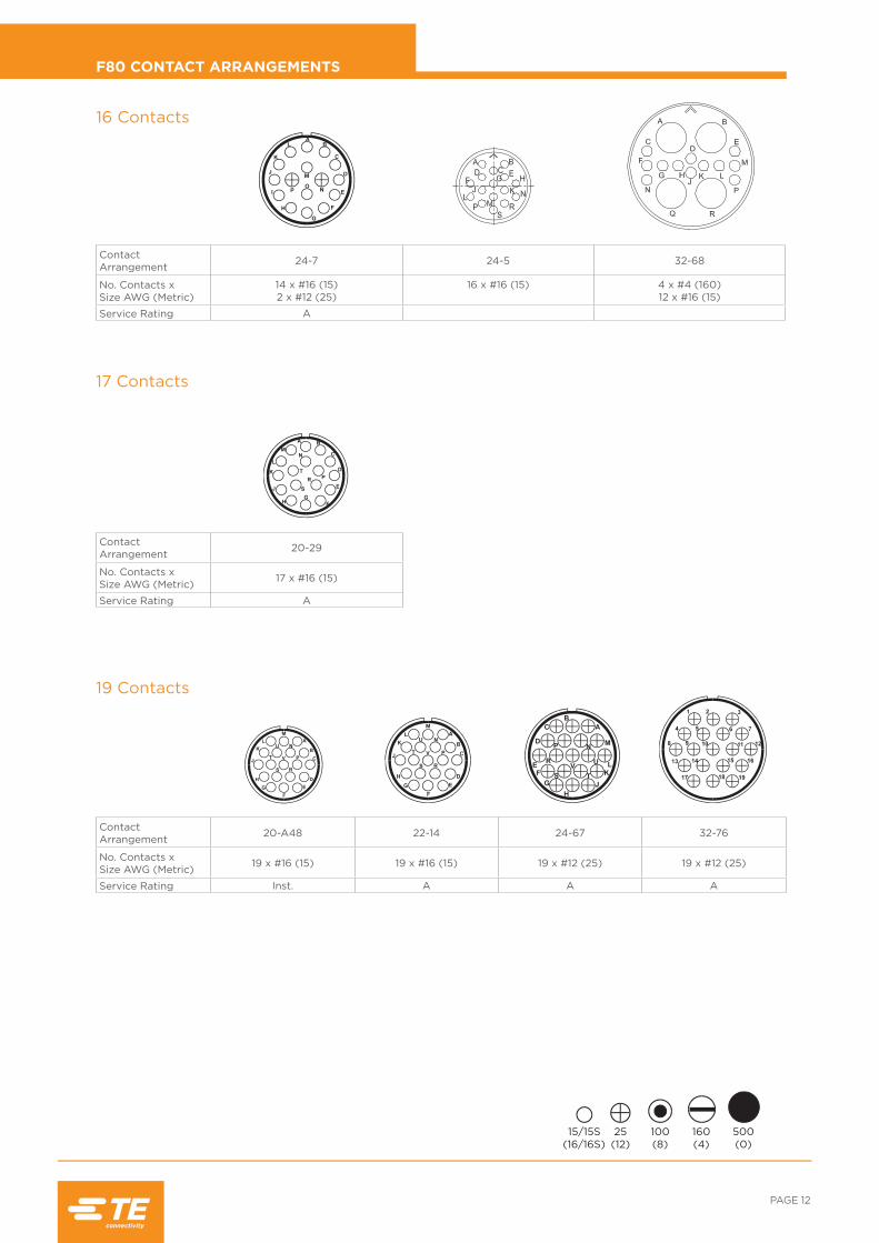
F80 CONTACT ARRANGEMENTS
16 Contacts
17 Contacts
D A
BC
15/15S(16/16S)
25(12)
100(8)
160(4)
500(0)
Contact Arrangement 20-29
No. Contacts x Size AWG (Metric) 17 x #16 (15)
Service Rating A
Contact Arrangement 24-7 24-5 32-68
No. Contacts x Size AWG (Metric)
14 x #16 (15) 2 x #12 (25)
16 x #16 (15) 4 x #4 (160) 12 x #16 (15)
Service Rating A
19 Contacts
Contact Arrangement 20-A48 22-14 24-67 32-76
No. Contacts x Size AWG (Metric) 19 x #16 (15) 19 x #16 (15) 19 x #12 (25) 19 x #12 (25)
Service Rating Inst. A A A

RAIL /// CIRH: MODULAR BAYONET LOCK CONNECTOR
F80 CONTACT ARRANGEMENTS
Contact Arrangement 28-16
No. Contacts x Size AWG (Metric) 20 x #16 (15)
Service Rating A
Contact Arrangement 28-11 36-A22
No. Contacts x Size AWG (Metric)
18 x # 16 (15) 4 x # 12 (25) 22 x # 12 (25)
Service Rating A
22 Contacts
20 Contacts
23 Contacts
21 Contacts
D A
BC
15/15S(16/16S)
25(12)
100(8)
160(4)
500(0)
Contact Arrangement 40-D21
No. Contacts x Size AWG (Metric)
20 x #12 (25) 1 x #8 (100)
Service Rating D
Contact Arrangement 32-6
No. Contacts x Size AWG (Metric)
2 x #4 (160) 3 x #8 (100) 2 x #12 (25)16 x #16 (15)
24 Contacts
Contact Arrangement 24-28
No. Contacts x Size AWG (Metric) 24 x #16 (15)
Service Rating Inst.

PAGE 14
F80 CONTACT ARRANGEMENTS
25 Contacts
D A
BC
15/15S(16/16S)
25(12)
100(8)
160(4)
500(0)
Contact Arrangement 24-A25
No. Contacts x Size AWG (Metric) 25 x #16 (15)
Service Rating A
Contact Arrangement 40-A31 32-31
No. Contacts x Size AWG (Metric) 31 x #12 (25) 31 x #16 (15)
Service Rating D
Contact Arrangement 28-12 28-13
No. Contacts x Size AWG (Metric) 26 x #16 (15) 28-12 Rotated by 1000
26 x #16 (15)
Service Rating A A
26 Contacts
31 Contacts

RAIL /// CIRH: MODULAR BAYONET LOCK CONNECTOR
F80 CONTACT ARRANGEMENTS
Contact Arrangement 28-15 32-7 40-A35
No. Contacts x Size AWG (Metric) 35 x #16 (15)
28 x #16 (15)7 x #12 (25)
35 x #12 (25)
Service Rating AA,B,H & J = Inst.
Balance = AD
35 Contacts
37 Contacts
32 Contacts
D A
BC
15/15S(16/16S)
25(12)
100(8)
160(4)
500(0)
Contact Arrangement 49-D32
No. Contacts x Size AWG (Metric)
26 x #12 (25) 2 x #8 (100)
4 x Coax
Service Rating D
Contact Arrangement 28-21
No. Contacts x Size AWG (Metric) 37 x #16 (15)
Service Rating A

PAGE 16
F80 CONTACT ARRANGEMENTS
38 Contacts
D A
BC
15/15S(16/16S)
25(12)
100(8)
160(4)
500(0)
Contact Arrangement 40-A38
No. Contacts x Size AWG (Metric) 38 x #12 (25)
Service Rating A
Contact Arrangement 36-7 36-16
No. Contacts x Size AWG (Metric)
40 x #16 (15)7 x #12 (25)
36-7 Rotated by 1000
Service Rating A A
47 Contacts
Contact Arrangement 36-17 40-9
No. Contacts x Size AWG (Metric) 36-7 Rotated by 2500
1 x #8 (100) 22 x #12 (25) 24 x #16 (15)
Service Rating A

RAIL /// CIRH: MODULAR BAYONET LOCK CONNECTOR
F80 CONTACT ARRANGEMENTS
Contact Arrangement 36-10 36-11
No. Contacts x Size AWG (Metric) 48 x #16 (15) 36-10 Rotated by 1000
Service Rating A A
Contact Arrangement 36-12 36-A48
No. Contacts x Size AWG (Metric) 36-10 Rotated by 2500 48 x # 16 (15)
Service Rating A Inst.
48 Contacts
49 Contacts
D A
BC
15/15S(16/16S)
25(12)
100(8)
160(4)
500(0)
Contact Arrangement 49-A49 49-D1
No. Contacts x Size AWG (Metric)
38 x #16 (15), 4 x #12 (25) 5 x #8 (100), 2 x #4 (160)
44 x #16 (15) 5 x #4 (160)
Service Rating D D

PAGE 18
F80 CONTACT ARRANGEMENTS
54 Contacts
D A
BC
15/15S(16/16S)
25(12)
100(8)
160(4)
500(0)
Contact Arrangement 32-22
No. Contacts x Size AWG (Metric) 54 x #16 (15)
Service Rating A
Contact Arrangement 32-A55
No. Contacts x Size AWG (Metric) 55 x #16 (15)
Contact Arrangement 40-A60
No. Contacts x Size AWG (Metric) 60 x #16 (15)
Service Rating A
55 Contacts
60 Contacts
Contact Arrangement 49-A57
No. Contacts x Size AWG (Metric)
54 x #12 (25) 3 x Coax
57 Contacts
Contact Arrangement 49-A68 49-D68
No. Contacts x Size AWG (Metric) 68 x # 12 (25)
57 x #12 (25) 10 x #16 (15)
1 x Coax
68 Contacts

RAIL /// CIRH: MODULAR BAYONET LOCK CONNECTOR
F80 CONTACT ARRANGEMENTS
Contact Arrangement 40-56
No. Contacts x Size AWG (Metric) 85 x # 16 (15)
Service Rating A
85 Contacts
D A
BC
15/15S(16/16S)
25(12)
100(8)
160(4)
500(0)
Contact Arrangement 49-74
No. Contacts x Size AWG (Metric) 74 x # 16 (15)
74 Contacts
Contact Arrangement 49-D75
No. Contacts x Size AWG (Metric)
73 x # 16 (15)2 x Coax
75 Contacts
Contact Arrangement 49-A76
No. Contacts x Size AWG (Metric) 76 x # 12 (25)
76 Contacts
Contact Arrangement 49-A95
No. Contacts x Size AWG (Metric) 95 x # 16 (15)
95 Contacts
PAGE 20
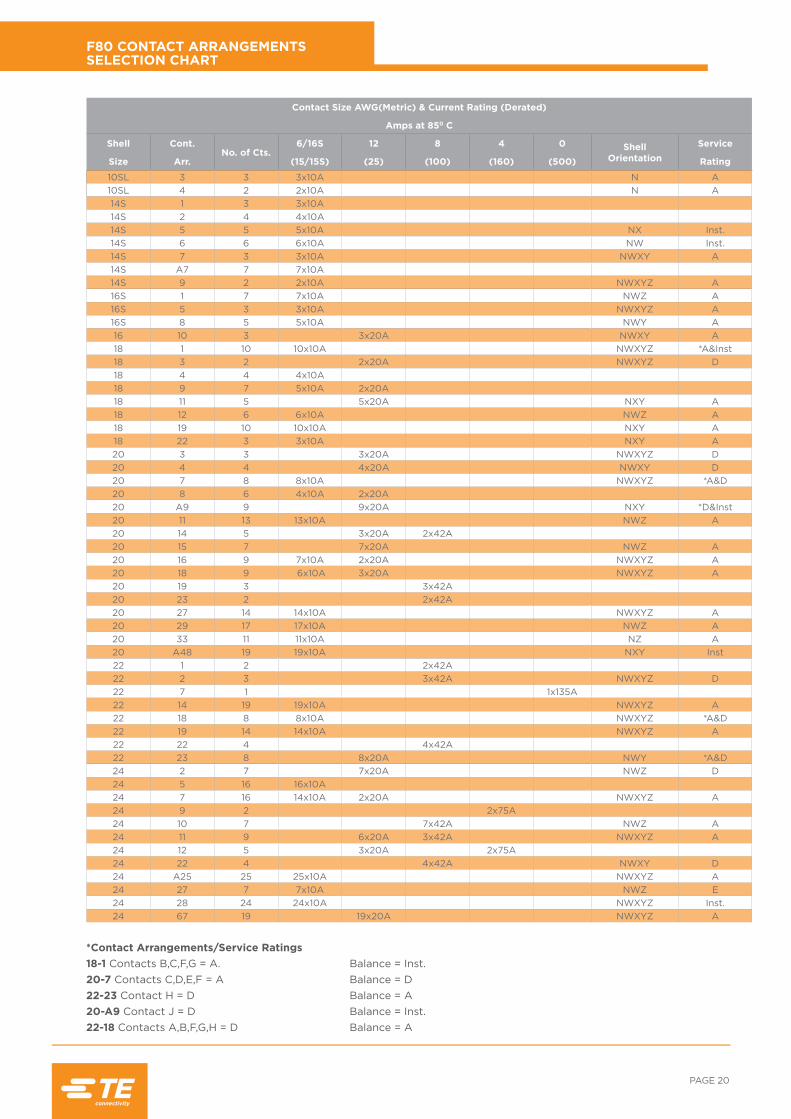
F80 CONTACT ARRANGEMENTS SELECTION CHART
*Contact Arrangements/Service Ratings18-1 Contacts B,C,F,G = A. Balance = Inst. 20-7 Contacts C,D,E,F = A Balance = D 22-23 Contact H = D Balance = A 20-A9 Contact J = D Balance = Inst.22-18 Contacts A,B,F,G,H = D Balance = A
Contact Size AWG(Metric) & Current Rating (Derated)
Amps at 850 C
Shell Cont.No. of Cts.
6/16S 12 8 4 0 Shell Orientation
Service
Size Arr. (15/15S) (25) (100) (160) (500) Rating
10SL 3 3 3x10A N A10SL 4 2 2x10A N A14S 1 3 3x10A14S 2 4 4x10A14S 5 5 5x10A NX Inst.14S 6 6 6x10A NW Inst.14S 7 3 3x10A NWXY A14S A7 7 7x10A14S 9 2 2x10A NWXYZ A16S 1 7 7x10A NWZ A16S 5 3 3x10A NWXYZ A16S 8 5 5x10A NWY A16 10 3 3x20A NWXY A18 1 10 10x10A NWXYZ *A&Inst18 3 2 2x20A NWXYZ D18 4 4 4x10A18 9 7 5x10A 2x20A18 11 5 5x20A NXY A18 12 6 6x10A NWZ A18 19 10 10x10A NXY A18 22 3 3x10A NXY A20 3 3 3x20A NWXYZ D20 4 4 4x20A NWXY D20 7 8 8x10A NWXYZ *A&D20 8 6 4x10A 2x20A20 A9 9 9x20A NXY *D&Inst20 11 13 13x10A NWZ A20 14 5 3x20A 2x42A20 15 7 7x20A NWZ A20 16 9 7x10A 2x20A NWXYZ A20 18 9 6x10A 3x20A NWXYZ A20 19 3 3x42A20 23 2 2x42A20 27 14 14x10A NWXYZ A20 29 17 17x10A NWZ A20 33 11 11x10A NZ A20 A48 19 19x10A NXY Inst22 1 2 2x42A22 2 3 3x42A NWXYZ D22 7 1 1x135A22 14 19 19x10A NWXYZ A22 18 8 8x10A NWXYZ *A&D22 19 14 14x10A NWXYZ A22 22 4 4x42A22 23 8 8x20A NWY *A&D24 2 7 7x20A NWZ D24 5 16 16x10A24 7 16 14x10A 2x20A NWXYZ A24 9 2 2x75A24 10 7 7x42A NWZ A24 11 9 6x20A 3x42A NWXYZ A24 12 5 3x20A 2x75A24 22 4 4x42A NWXY D24 A25 25 25x10A NWXYZ A24 27 7 7x10A NWZ E24 28 24 24x10A NWXYZ Inst.24 67 19 19x20A NWXYZ A

RAIL /// CIRH: MODULAR BAYONET LOCK CONNECTOR
*Contact Arrangements/Service Ratings32-7 Contacts A,B,H,J = Inst Balance = A
F80 CONTACT ARRANGEMENTS SELECTION CHART
Contact Size AWG(Metric) & Current Rating (Derated)Amps at 850 C
Shell Cont.No. of Cts.
6/16S 12 8 4 0 Shell Orientation
Service
Size Arr. (15/15S) (25) (100) (160) (500) Rating28 1 9 6x20A 3x42A28 C1 13 12x10A28 T2 228 3 3 3x42A28 6 3 3x75A28 8 8 6x10A 2x75A28 T9 9 5x10A28 10 7 3x20A 2x42A 2x75A28 11 22 18x10A 4x20A NWXYZ A28 12 26 26x10A NWXY A28 13 26 26x10A - A28 15 35 35x10A NWXYZ A28 16 20 20x10A NWXYZ A28 20 14 4x10A 10x20A NWXYZ A28 21 37 37x10A NWXYZ A28 22 6 3x10A 3x75A NWXYZ D28 A9 9 5X10A 4X75A NWXYZ A32 5 2 2x135A32 6 23 16x10A 2x20A 3x42A 2x75A32 7 35 28x10A 7x20A NWXYZ *A&Inst32 A13 13 13x20A NWXYZ D32 17 4 4x75A NWXY D32 C17 432 22 54 54x10A NWXYZ A32 31 31 31x10A32 A55 55 55x10A NWXYZ A32 68 16 12x10A 4x75A32 76 19 19x20A NWXYZ A36 5 4 4x135A NXY A36 7 47 40x10A 7x20A 4x135A NWXYZ A36 10 48 48x10A NWXYZ A36 11 48 48x10A - A36 12 48 48x10A - A36 16 47 40x10A 7x20A - A36 17 47 40x10A 7x20A - A36 A22 22 22x20A NWXYZ D36 A48 48 48x10A NW Inst36 54 39 31x10A 8x42A NW A36 D68 14 4x10A 10x42A36 D78 14 4x10A 10x42A40 56 85 85x10A NWXYZ A40 A5 5 5x135A NWZ A40 D6 6 3x10A 3x135A40 9 47 24x10A 22x20A 1X42A40 D21 21 20x20A 1x42A NW D40 A31 31 31x20A NWXYZ D40 A35 35 35x20A NWXYZ D40 A38 38 38x20A NWXYZ A40 A60 60 60x10A NWXYZ A40 E4 4 4x135A NWX E49 D1 49 44x10A 5xCoax NW D49 A4 4 4x135A NW D49 D4 4 2X20A49 A10 10 4x20A 6x135A NWX D49 A12 12 5x42A 7x75A NW D49 D32 32 26x20A 2x42A 4xCoax NW D49 A49 49 38x10A 4x20A 5x42A 2xCoax NW D49 A57 57 54x20A49 A68 68 68x20A49 D68 68 10x10A 57x20A49 74 74 74x10A49 D75 75 73x10A49 A76 76 76x20A49 A95 95 95x10A

PAGE 22
ALTERNATIVE INSERT ORIENTATIONS
View on Mating Face of Pin Inserts
A
B
C
Z
A B
C
Y
A
B C
X
A
B
C
W
A
B
C
N
Contact Arrangement
Angular Displacement Of Insert
N Yellow W Blue X Green Y Purple Z White
10SL-3 010S-4 014S-114S-214S-5 0 11014S-6 0 9014S-7 0 90 180 270
14S-A714S-9 0 70 145 215 29016S-1 0 80 28016S-5 0 70 145 215 29016S-8 0 170 26516-10 0 90 180 27018-1 0 70 145 215 29018-3 0 35 110 250 32518-418-918-11 0 170 26518-12 0 80 28018-19 0 120 24018-2220-3 0 70 145 215 29020-4 0 45 110 25020-7 0 80 110 250 28020-8
20-A9 0 110 25020-1120-1420-15 0 80 28020-16 0 80 110 250 28020-18 0 35 110 250 32520-1920-2320-27 0 35 110 250 32520-29 0 80 28020-33 0 280
20-A48 0 80 28022-122-2 0 70 145 215 29022-722-14 0 80 110 250 28022-18 0 80 110 250 28022-19 0 80 110 250 28022-2222-23 0 35 25024-1 0 80 28024-524-7 0 80 110 250 28024-924-10 0 80 28024-11 0 35 110 250 32524-1224-22 0 45 110 250
24-A25 0 80 110 250 28024-27 0 80 28024-28 0 80 110 250 28024-67 0 80 335

RAIL /// CIRH: MODULAR BAYONET LOCK CONNECTOR
View on Mating Face of Pin Inserts
ALTERNATIVE INSERT ORIENTATIONS
A
B
C
Z
A B
C
Y
A
B C
X
A
B
C
W
A
B
C
N
Contact ArrangementAngular Displacement Of Insert
N Yellow W Blue X Green Y Purple Z White28-1
28-C128-T228-328-628-828-T928-1028-11 0 80 110 250 28028-12 0 90 180 27028-13 028-15 0 80 110 250 28028-16 0 80 110 250 28028-20 0 80 110 250 28028-21 0 80 110 250 28028-22 0 70 145 215 29028-A9 0 110 250 260 28032-532-632-7 0 80 125 235 280
32-A13 0 65 130 230 29532-17 0 45 110 250
32-C1732-22 0 80 110 250 28032-31
32-A55 0 80 110 250 28032-6832-76 0 80 110 250 28036-5 0 120 24036-7 0 80 110 250 28036-10 0 80 125 235 28036-11 036-12 036-16 036-17 0
36-A22 0 80 110 250 28036A48 0 6536-54 0 67
36-D6840-56 0 72 144 216 28840-A5 0 33 27040-D640-9
40-D21 0 8040-A31 0 80 110 250 28040-A35 0 70 130 230 29040-A38 0 37 74 285 32240-A60 0 80 110 250 28040-E4 0 45 11049-D1 0 8049-A4 0 8049-D449-A10 0 80 15049-A12 0 8049-D32 049-A49 0 8049-57
49-A6849-D6849-74
49-D7549-A7649-A95

PAGE 24
F80 CRIMP CONTACTS PIN
Contact SizeAWG (Metric) Part Number A B C Conductor
CSA mm2 L
16S/20 CIRB16S/20KPKF80 3,200.126
2,650.104
1,100.043 0,50/0,60 26,60
1.047
16S/18 CIRB16S/18KPKF80 3,200.126
2,300.091
1,250.049 0,75/0,93 26,60
1.047
16S (15S) CIRB16SKPKF80 3,200.126
2,750.108
1,75 0.069 0,93/1,50 26,60
1.047
16S/14 CIRB16S/14KPKF80 3,200.126
2,900.114
1,800.071 1,94/2,08 26,60
1.047
16/22 CIRB16/22KPKF80 3,20 0.126
2,300.091
0,900.035 0,22/0,34 31,75
1.250
16/20 CIRB16/20KPKF80 3,200.126
2,650.104
1,100.043 0,50/0,75 31,75
1.250
16/18 CIRB16/18KPKF80 3,200.126
2,300.091
1,250.049 0,75/0,93 31,75
1.250
16 (15) CIRB16KPKF80 3,200.126
2,750.108
1,750.069 0,93/1,50 31,75
1.250
16/14 CIRB1614KPKF80 3,200.126
2,900.114
1,80 0.071 1,94/2,08 31,75
1,250
16/12 CIRB16/12KPKF80 3,200.126
3,800.150
2,500.098 2,50/3,00 31,75
1.250
12/20 CIRB12/20KPKF80 4,800.189
2,650.104
1,100.043 0,50/0,60 37,50
1.476
12/18 CIRB12/18KPKF80 4,800.189
2,300.091
1,250.049 0,75/0,93 37,50
1.476
12/16 (25/15) CIRB12/16KPKF80 4,800.189
2,750.108
1,750.069 0,93/1,50 37,50
1.476
12/14 CIRB12/14KPKF80 4,800.189
2,900.114
1,800.071 1,94/2,08 37,50
1.476
12 (25) CIRB12KPKF80 4,800.189
3,800.150
2,500.098 2,50/3,00 37,50
1.476
12/10 CIRB1210KPKF80 4,800.189
4,400.173
3,00 0.118 5,53 37,50
1.476
12/40 (25/40) CIRB12/40KPKF80 4,800.189
4,000.157
2,700.106 4,00 37,50
1.476
8/40 (100/40) CIRB8/40KPKF80 7,800.307
5,200.205
2,900.114 4,00 40,70
1.602
8/12 CIRB8/12KPKF80 7,800.307
3,800.150
2,500.098 2,50 40,70
1.602
8/10 CIRB8/10KPKF80 7,800.307
5,200.205
3,300.130 5,53 40,70
1.602
8 CIRB8KPKF80 7,800.307
6,800.268
4,550.179 9,00 40,70
1.602
(100/60) CIRB100/60KPKF80 7,800.307
5,500.217
3,400.134 6,00 40,70
1.602
(100) CIRB100KPKF80 7,800.307
7,000.276
4,400.173 10,00 40,70
1.602
4/10 CIRB4/10KPKF80 11,000.433
5,200.205
3,300.130 553 41,25
1.624
4 CIRB4KPKF80 11,000.433
9,550.376
7,100.280 22,00 41,25
1.624
(160) CIRB160KPKF80 11,000.433
9,450.372
5,700.224 16,00 41,25
1.624
0 CIRB0KPKF80 15,000.591
14,350.565
11,500.453 53,0 44,50
1.752
(500/160) CIRB500/160KPKF80 15,000.591
9,450.372
5,70 0.224 16,00 44,50
1.752
(500/250) CIRB500/250KPKF80 15,000.591
10,000.394
7,000.276 25,00 44,50
1.752
(500/350) CIRB500/350KPKF80 15,000.591
11,900.468
8,000.315 35,00 44,50
1.752
(500) CIRB500KPKF80 15,000.591
14,350.565
9,800.386 50,00 44,50
1.752
MetricImperial
For standard gold plating, add P3 to theend of the part number.

RAIL /// CIRH: MODULAR BAYONET LOCK CONNECTOR
Contact SizeAWG (Metric) Part Number A B C D Conductor
CSA mm2 L
16S/20 CIRB16S/20KSKF80 3,200.126 - 2,65
0.1041,10
0.049 0,50/0,60 26,601.047
16S/18 CIRB16S/18KSKF80 3,200.126 - 2,30
0.0911,25
0.069 0,75/0.93 26,601.047
16S (15S) CIRB16SKSKF80 3,200.126 - 2,75
0.1081,75
0.069 0,93/1,50 26,601.047
16S/14 CIRB16S/14KSKF80 3,200.126 - 3,90
0.1141,80
0.071 1,94/2,08 26,601.047
16/22 CIRB16/22KSKF80 3,20 0.126 - 2,30
0.0910,90
0.035 0,22/0,34 36,501.437
16/20 CIRB16/20KSKF80 3,200.126 - 2,65
0.1041,10
0.049 0,50/0,75 36,501.437
16/18 CIRB16/18KSKF80 3,200.126 - 2,30
0.0911,25
0.049 0,75/0,93 36,501.437
16 (15) CIRB16KSKF80 3,200.126 - 2,75
0.1081,750.07 0,93/1,50 36,50
1.437
16/14 CIRB16/14KSKF80 3,200.126 - 2,90
0.1141,80
0.071 1,94/2,08 36,501.437
16/12 CIRB16/12KSKF80 3,200.126 - 3,80
0.1502,50
0.098 2,50/3,00 36,501.476
12/20 CIRB12/20KSKF80 4,800.189 - 2,65
0.1041,10
0.049 0,50/0,60 37,501.476
12/18 CIRB12/18KSKF80 4,800.189 - 2,30
0.0911,25
0.049 0,75/0,93 37,501.476
12/16 (25/15) CIRB12/16KSKF80 4,800.189 - 2,75
0.1081,75
0.069 0,93/1,50 37,501.476
12/14 CIRB12/14KSKF80 4,800.189 - 2,90
0.1141,80
0.071 1,94/2,08 37,501.476
12 (25) CIRB12KSKF80 4,800.189 - 3,80
0.1502,50
0.098 2,50/3,00 37,501.476
12/10 CIRB1210KSKF80 4800.189 - 4,40
0.1733,00 0.118 5,53 37,50
1.476
12/40 (25/40) CIRB12/40KSKF80 4,800.189 - 4,00
0.1572,70
0.106 4,00 37,501.476
8/40 CIRB8/40KSKF80 7,800.307
6,500.256
5,200.204
2,900.114 4,00 40,70
1.602
8/12 CIRB8/12KSKF80 7,800.307
6,500.256
3,800.150
2,500.098 2,50/3,00 40,70
1.602
8/10 CIRB8/10KSKF80 7,800.307
6,500.256
4,400.173
3,000.118 5,53 40,70
1.602
8 CIRB8KSKF80 7,800.307
6,500.256
6,800.268
4,550.179 9,00 40,70
1.602
(100/60) CIRB100/60KSKF80 7,800.307
6,500.256
5,500.217
3,400.134 6,00 40,70
1.602
(100) CIRB100KSKF80 7,800.307
6,500.256
7,000.276
4,400.173 10,00 40,70
1.602
4/10 CIRB4/10KSKF80 11,100.437
6,500.256
5,200.205
3,300.130 5,53 41,25
1.624
4 CIRB4KSKF80 11,100.437
8,600.339
9,550.376
7,100.280 22,00 41,25
1.624
(160) CIRB160KSKF80 11,100.437
8,600.339
9,450.372
5,700.224 16,00 41,25
1.624
0 CIRB0KSKF80 15,100.594
13,200.520
14,350.565
11,500.453 53,00 44,50
1.752
(500/160) CIRB500/160KSKF80 15,100.594
13,200.520
9,45 0.372
5,70 0.224 16,00 44,50
1.752
(500/250) CIRB500/250KSKF80 15,100.594
13,200.520
10,000.394
7,000.276 25,00 44,50
1.752
(500/350) CIRB500/350KPKF80 15,100.594
13,200.520
11,900.469
8,000.315 35,00 44,50
1.752
(500) CIRB500KPKF80 15,100.594
13,200.520
14,350.565
9.800.386 50,00 44,50
1.752
MetricImperial
For standard gold plating, add P3 to theend of the part number.
F80 CRIMP CONTACTS SOCKET

PAGE 26
F80 CRIMP CONTACTS LOW INSERTION FORCE SOCKET
Standard finish = gold plated.MetricImperial
Contact Size AWG (Metric)
PartNumber A B C Conductor
CSA mm2 L
16S(15S) CIRB16SKLKF80P3 3,20
0.1262,75
0.1081,75
0.069 1,00/1,50 26,601.047
16/22 CIRB16/22KLKF80P3 3,200.126
2,300.091
0,900.035 0,22/0,34 36,50
1.437
16/20 CIRB16/20KLKF80P3 3,200.126
2,650.104
1,100.043 0,50/0,60 36,50
1.437
16/18 CIRB16/18KLKF80P3 3,200.126
2,300.091
1,250.049 0,75/0,93 36,50
1.437
16(15) CIRB16KLKF80P3 3,20
0.1262,75
0.1081,75
0.069 1,00/1,50 36,501.437
16/14 CIRB16/14KLKF80P3 3,200.126
2,900.114
1,800.071 1,94/2,08 36,50
1.437
16/12 CIRB16/12KLKF80P3 3,200.126
3,800.150
2,500.098 2,50/3,00 36,50
1.437
12/40(25/40) CIRB12/40KLKF80P3 4,80
0.1894,000.157
2,700.106 4,00 37,50
1.476
12/20 CIRB12/20KLKF80P3 4,800.189
2,650.104
1,100.043 0,50/0,60 37,50
1.476
12/18 CIRB12/18KLKF80P3 4,800.189
2,300.091
1,250.049 0,75/0,93 37,50
1.476
12/16 CIRB12/16KLKF80P3 4,800.189
2,750.108
1,750.069 1,00/1,50 37,50
1.476
12/10 CIRB12/10KLKF80P3 4,800.189
4,400.175
3,000.118 5,53 37,50
1.476
12(25) CIRB12KLKF80P3 4,80
0.1893,80
0.15082,50
0.098 2,50/3,00 37,501.476

RAIL /// CIRH: MODULAR BAYONET LOCK CONNECTOR
Contact SizeAWG* Part Number A B C D L Use With
Conductors
4 CIRB 4 CKPK F80 P1 001 11,100.437
9,800.386
5,200.205
1,070.042
44,701.760 0.5 mm2
4 CIRB 4 CKPK F80 P1 002 11,100.437
9,800.386
7,500.295
1,750.069
44,701.760 1.0 mm2
Contact SizeAWG* Part Number A B C D L Use With
Conductors
4 CIRB 4 CKSK F80 P1 001 11,100.437
9,800.386
5,200.205
1,070.042
43,051.695 0.5 mm2
4 CIRB 4 CKSK F80 P1 002 11,100.437
9,800.386
7,500.295
1,750.069
43,051.695 1.0 mm2
MetricImperial
MetricImperial
* Important Note.Consult TE for suitable contact arrangement details.
* Important Note.Consult TE for suitable contact arrangement details.
F80 CRIMP CONTACTS COAXIAL PIN & SOCKET
Pin Contact
Socket Contact
LØ
A
ØD
ØC
ØB
ØD
ØC
ØA
LØ
B
L
ØA
ØD
ØC
ØB
ØD
ØC
ØA
L
ØB

PAGE 28
F80 CRIMP CONTACTS TWINAXIAL PIN & SOCKET
Contact SizeAWG* Part Number A B C D E L Use With
Conductors
4 CIRB 4 TKPK F80 P1 11,100.437
9,800.386
6,000.236
1,070.042
1,050.041
44,701.760
0.5 mm2
0.6 mm2
4 CIRB 4 TKPK F80 P1 001 11,100.437
9,800.386
6,500.256
1,300.051
1,300.051
44,701.760
0.75 mm2
1.0 mm2
Contact SizeAWG* Part Number A B C D E L Use With
Conductors
4 CIRB 4 TKSK F80 P1 11,100.437
9,800.386
6,000.236
1,070.042
1,050.041
43,051.695
0.5 mm2
0.6 mm2
4 CIRB 4 TKSK F80 P1 001 11,100.437
9,800.386
6,500.256
1,300.051
1,300.051
43,051.695
0.75 mm2
1.0 mm2
MetricImperial
MetricImperial
* Important Note.Consult TE for suitable contact arrangement details.
* Important Note.Consult TE for suitable contact arrangement details.
Pin Contact
Socket Contact
L
ØA
ØE
ØD
ØC
ØB
L
ØE
ØA
ØD
ØC ØB
L
ØA
ØE
ØD
ØC
ØB
L
ØE
ØA
ØD
ØC ØB

RAIL /// CIRH: MODULAR BAYONET LOCK CONNECTOR
C
C
H
E
øM
Om
P (max. panel thickness)
4 Holes ød1
4 Tapped holes d2 (M6 MOD.)B
Shell Size
BMax
CMax
d1+0,2 -0
+0.008-0
d2Thread
EMax
MMax
HMax
Om MinOverlapMated
10SL 17,60 0.693
25,701.012
3,200.126
M40,7-6H
3,000.118
16,100.634
25,000.98
11,100.437
14S 18,000.709
30,301.193
3,200.126
M40,7-6H
3,400.134
19,200.756
25,000.98
11,10 0.437
16S 18,00 0.709
32,801.291
3,200.126
M40,7-6H
3,400.134
22,400.882
25,000.98
11,10 0.437
16 22,800.898
32,801.291
3,200.126
M40,7-6H
3,400.134
22,400.882
32,851.293
15,850.624
18 23,600.929
35,301.390
3,200.126
M40,7-6H
4,200.165
25,601.008
32,851.293
15,850.624
20 23,60 0.929
38,301.508
3,200.126
M40,7-6H
4,200.165
29,001.142
32,851.293
15,850.624
22 23,600.929
41,301.626
3,200.126
M40,7-6H
4,200.165
31,901.256
32,851.293
15,750.620
24 25,200.992
44,801.764
3,700.146
M40,7-6H
4,200.165
35,001.378
32,851.293
15,750.620
28 25,200.992
51,102.012
3,700.146
M50,8-6H
4,200.165
41,401.630
32,851.293
15,750.620
32 26,801.055
57,302.256
4,300.169
M50,8-6H
4,200.165
47,801.882
32,851.293
15,750.620
36 26,801.055
63,802.512
4,300.169
M50,8-6H
4,200.165
52,602.071
32,851.293
15,750.620
40 26,801.055
70,202.764
4,300.169
M50,8-6H
4,200.165
59,002.323
32,851.293
15,750.620
See page 90 for panel mounting details.
SQUARE FLANGE RECEPTACLE FRONT MOUNTING (NO ACCESSORY THREAD) STYLE: CIRH00A/CIRH00A...M6
MetricImperial

PAGE 30
SQUARE FLANGE RECEPTACLE FRONT MOUNTING STYLE: CIRH00T/CIRH00T...M6
Shell Size
BMax
CMax
d1+0,2 -0
+0.008-0
d2Thread
EMax
F Thread Dia. Class
2A
HMax P
Om MinOverlapMated
10SL 17,60 0.693
25,701.012
3,200.126
M40,7-6H
3,000.118
5/8" x 24 UNEF 28,781.133
3,300.130
11,100.437
14S 18,000.709
30,301.193
3,200.126
M40,7-6H
3,400.134
3/4" x 20 UNEF 28,781.133
3,300.130
11,10 0.437
16S 18,00 0.709
32,801.291
3,200.126
M40,7-6H
3,400.134
7/8" x 20 UNEF 28,781.133
3,300.130
11,10 0.437
16 22,800.898
32,801.291
3,200.126
M40,7-6H
3,400.134
7/8" x 20 UNEF 36,301.429
3,300.130
15,850.624
18 23,600.929
35,301.390
3,200.126
M40,7-6H
4,200.165 1" x 20 UNEF 36,30
1.4293,300.130
15,850.624
20 23,60 0.929
38,301.508
3,200.126
M40,7-6H
4,200.165 1 1/8" x 18 UNEF 36,30
1.4293,300.130
15,850.624
22 23,600.929
41,301.626
3,200.126
M40,7-6H
4,200.165 1 1/4" x 18 UNEF 36,30
1.4293,300.130
15,750.620
24 25,200.992
44,801.764
3,700.146
M40,7-6H
4,200.165 1 3/8" x 18 UNEF 36,30
1.4293,300.130
15,750.620
28 25,200.992
51,102.012
3,700.146
M50,8-6H
4,200.165 1 5/8" x 18 UNEF 36,30
1.4293,300.130
15,750.620
32 26,801.055
57,302.256
4,300.169
M50,8-6H
4,200.165 1 7/8" x 16 UN 36,30
1.4293,300.130
15,750.620
36 26,801.055
63,802.512
4,300.169
M50,8-6H
4,200.165 21/16" x 16 UNS 36,30
1.4293,300.130
15,750.620
40 26,801.055
70,202.764
4,300.169
M50,8-6H
4,200.165 2 5/16" x 16 UN 36,30
1.4293,300.130
15,750.620
See page 90 for panel mounting details.Metric
Imperial
C
C
H
E
øF
Om
P (max. panel thickness when using accessory)
4 Holes ød1
4 Tapped holes d2 (M6 MOD.)B

RAIL /// CIRH: MODULAR BAYONET LOCK CONNECTOR
Shell Size A B C D E F G H J
10SL 109,00 4.291
44,001.732
57,002.244
58,002.283
54,002.126
54,002.126
49,001.929
53,002.087 *
14S 107,004.213
44,001.732
61,002.402
60,002.362
56,002.205
56,002.205
49,001.929
53,002.087 *
16S 104,00 4.094
44,001.732
64,002.520
64,002.520
60,002.362
60,002.362
49,001.929
53,002.087 *
16 111,004.370
54,002.126
71,002.795
71,002.795
67,002.638
67,002.638
57,002.244
65,002.559 *
18 115,004.528
54,002.126
76,002.992
76,002.992
72,002.835
72,002.835
59,002.323
65,002.559
74,002.913
20 114,00 4.488
54,002.126
81,003.189
82,003.228
77,003.031
77,003.031
60,002.362
68,002.677
80,003.150
22 114,004.488
54,002.126
81,002.189
82,003.228
77,003.031
77,003.031
63,002.480
68,002.677
80,003.150
24 109,004.291
54,002.126
89,003.504
89,003.504
85,003.346
85,003.346
60,002.362
68,002.677
80,003.150
28 119,004.685
54,002.126
88,003.465
89,003.504
85,003.346
85,003.346
63,002.480
67,002.638
81,003.189
32 115,004.528
54,002.126
98,003.858
101,003.976
95,003.740
95,003.740
61,002.402
67,002.638
80,003.189
36 112,004.409
54,002.126
104,004.094
105,004.134
101,003.976
101,003.976
67,002.638
68,002.677
80,003.189
40 N/A 54,002.126
111,004.370
112,004.409
107,004.213
107,004.213
68,002.677
68,002.677
80,003.189
* Please consult TE for availability.
CIRH ‘00’ STYLE CONNECTOR & ACCESSORY
MetricImperial
J
CIRH00GS
H
CIRH00GM
G
CIRH00G
D
CIRH00FC
E
CIRH00FT
F
CIRH00FM
C
CIRH00FB
CIRH00EVA
CIRH00D

PAGE 32
CIRH ‘00’ STYLE CONNECTOR & ACCESSORY CONT.
Shell Size K L M N P R S T U
10SL 50,001.969
122,004.803
81,003.189
121,004.764
53,002.087
51,002.008
82,003.228
140,005.512
101,003.976
14S 50,001.969
118,004.646
81,003.189
118,004.646
56,002.205
51,002.008
82,003.228
137,005.394
101,003.976
16S 50,001.969
120,004.724
81,003.189
115,004.528
56,002.205
51,002.008
82,003.228
134,005.276
101,003.976
16 57,002.244
123,004.843
88,003.465
124,004.882
63,002.480
60,002.362
91,003.583
152,005.984
121,004.764
18 59,002.323
124,004.882
92,003.622
126,004.961
66,002.598
66,002.598
99,003.898
148,005.827
121,004.764
20 59,002.323
120,004.724
92,003.622
123,004.843
66,002.598
66,002.598
99,003.898
145,005.709
121,004.764
22 59,002.323
120,004.724
92,003.622
123,004.843
66,002.598
66,002.598
99,003.898
145,005.709
121,004.764
24 59,002.323
107,004.213
95,003.740
123,004.843
66,002.598
69,002.716
105,004.134
142,005.591
124,004.882
28 59,002.323
107,004.213
95,003.740
124,004.882
65,002.559
70,002.756
106,004.173
149,005.866
131,005.157
32 58,002.283
106,004.173
100,003.937
120,004.724
65,002.559
69,002.716
111,004.370
146,005.748
137,005.394
36 58,002.283
106,004.173
107,004.213
117,004.606
65,002.559
69,002.716
117,004.606
143,005.630
144,005.669
40 58,00 2.283
103,004.055
107,004.213
114,004.488
65,002.559
70,002.756
112,004.409
140,005.512
144,005.669
MetricImperial
S
CIRH00RC
T
CIRH00XLAU
CIRH00XLC
R
CIRH00R
P
CIRH00M
N
CIRH00JE
K
CIRH00H
L
CIRH00HC
M
CIRH00HD

RAIL /// CIRH: MODULAR BAYONET LOCK CONNECTOR
D
C
H
E
øF
Om
B
Shell Size
BMax
CMax
DMax
EMax
F Thread Dia. Class
2A
HMax
Om Min Overlap Mated
10SL 17,600.693
25,200.992
20,800.819
3,000.118
5/8" x 24 UNEF 28,781.133
11,100.437
14S 18,000.709
29,801.173
25,601.008
3,400.134
3/4" x 20 UNEF 28,781.133
11,100.437
16S 18,000.709
32,301.272
28,801.134
3,400.134
7/8" x 20 UNEF 28,781.133
11,100.437
16 22,800.898
32,301.272
28,801.134
3,400.134
7/8" x 20 UNEF 36,301.429
15,850.624
18 23,600.929
34,801.370
31,901.256
4,200.165 1" x 20 UNEF 36,30
1.42915,850.624
20 23,600.929
37,801.488
35,101.382
4,200.165 1 1/8" x 18 UNEF 36,30
1.42915,850.624
22 23,600.929
41,101.618
38,301.508
4,200.165 1 1/4" x 18 UNEF 36,30
1.42915,75
0.620
24 25,200.992
44,601.756
41,501.634
4,200.165 1 3/8" x 18 UNEF 36,30
1.42915,75
0.620
28 25,200.992
50,902.004
47,801.882
4,200.165 1 5/8" x 18 UNEF 36,30
1.42915,75
0.620
32 26,801.055
57,102.248
54,202.134
4,200.165 1 7/8" x 16 UN 36,30
1.42915,75
0.620
36 26,801.055
63,802.512
60,802.394
4,200.165 2 1/16" x 16 UNS 36,30
1.42915,75
0.620
40 26,801.055
70,002.756
66,702.626
4,200.165 2 5/16" x 16 UN 36,30
1.42915,75
0.620
CABLE MOUNTED RECEPTACLE STYLE: CIRH01T
MetricImperial

PAGE 34
CIRH ‘01’ STYLE CONNECTOR & ACCESSORY
Shell Size A B G H J K L M N
10SL 109,004.291
44,001.732
49,001.929
53,002.087 * 50,00
1.696122,004.803
81,003.189
121,004.764
14S 107,004.213
44,001.732
49,001.929
53,002.087 * 50,00
1.969118,004.646
81,003.189
118,004.646
16S 104,004.094
44,001.732
49,001.929
53,002.087 * 50,00
1.969120,004.724
81,003.189
115,004.528
16 111,004.370
54,002.126
57,002.244
65,002.559 * 57,00
2.244123,004.843
88,003.465
124,004.882
18 115,004.528
54,002.126
59,002.323
65,002.559
74,002.913
59,002.323
124,004.882
92,003.622
126,004.961
20 114,004.488
54,002.126
60,002.362
68,002.677
80,003.150
59,002.323
120,004.724
92,003.622
123,004.843
22 114,004.488
54,002.126
63,002.480
68,002.677
80,003.150
59,002.323
120,004.724
92,003.622
123,004.843
24 109,004.291
54,002.126
60,002.362
68,002.677
80,003.150
59,002.323
107,004.213
95,003.740
123,004.843
28 119,004.685
54,002.126
63,002.480
67,002.638
81,003.189
59,002.323
107,004.213
95,003.740
124,004.882
32 115,004.528
54,002.126
61,002.402
67,002.638
80,003.189
58,002.283
106,004.173
100,003.937
120,004.724
36 112,004.409
54,002.126
67,002.638
68,002.677
80,003.189
58,002.283
106,004.173
107,004.213
117,004.606
40 N/A 54,002.126
68,002.677
68,002.677
80,003.189
58,002.283
103,004.055
107,004.213
114,004.488
* Please consult TE for availability.
MetricImperial
M
CIRH01HD
N
CIRH01JE
L
CIRH01HCK
CIRH01H
J
CIRH01GS
A
CIRH01D
B
CIRH01EV
G
CIRH01GH
CIRH01GM

RAIL /// CIRH: MODULAR BAYONET LOCK CONNECTOR
Shell Size P R S T U
10SL 53,002.087
51,002.008
82,003.228
140,005.512
101,003.976
14S 56,002.205
51,002.008
82,003.228
137,005.394
101,003.976
16S 56,002.205
51,002.008
82,003.228
134,005.276
101,003.976
16 56,002.205
60,002.362
91,003.583
152,005.984
121,004.764
18 63,002.480
66,002.598
99,003.898
148,005.827
121,004.764
20 66,002.598
66,002.598
99,003.898
145,005.709
121,004.764
22 66,002.598
66,002.598
99,003.898
145,005.709
121,004.764
24 66,002.598
69,002.716
105,004.134
142,005.591
124,004.882
28 66,002.598
70,002.756
106,004.173
149,005.866
131,005.157
32 66,002.598
69,002.716
111,004.370
146,005.748
137,005.394
36 66,002.598
69,002.716
117,004.606
143,005.630
144,005.669
40 66,002.598
70,002.756
112,004.409
140,005.512
144,005.669
CIRH ‘01’ STYLE CONNECTOR & ACCESSORY CONT.
MetricImperial
U
CIRH01XLC
T
CIRH01XLA
P
CIRH01M
R
CIRH01R
S
CIRH01RC

PAGE 36
SQUARE FLANGE RECEPTACLE REAR MOUNTING (NO ACCESSORY THREAD) STYLE: CIRH03A/CIRH03A...M6
Shell Size
BMax
CMax
d1+0,2 -0
+0.008-0
d2Thread
EMax
MMax
HMax
P See Note
Om MinOverlap Mated
10SL 18,600.732
25,701.012
3,200.126
M40,7-6H
3,000.118
16,100.634
25,000.99
3,300.130
11,100.437
14S 18,600.732
30,301.193
3,200.126
M40,7-6H
3,400.134
19,200.756
25,000.99
3,300.130
11,100.437
16S 18,600.732
32,801.291
3,200.126
M40,7-6H
3,400.134
22,400.882
25,000.99
3,300.130
11,100.437
16 21,900.862
32,801.291
3,200.126
M40,7-6H
3,400.134
22,400.882
32,701.28
3,300.130
15,850.624
18 23,450.923
35,301.390
3,200.126
M40,7-6H
4,200.165
25,601.008
32,701.28
3,300.130
15,850.624
20 23,450.923
38,301.508
3,200.126
M40,7-6H
4,200.165
29,001.142
33,401.32
3,300.130
15,850.624
22 23,450.923
41,301.626
3,200.126
M40,7-6H
4,200.165
31,901.250
33,401.32
3,300.130
15,750.620
24 23,450.923
44,801.764
3,700.146
M40,7-6H
4,200.165
35,001.380
32,751.29
3,300.130
15,750.620
28 24,450.963
51,102.012
3,700.146
M50,8-6H
4,200.165
41,401.630
35,801.41
3,300.130
15,750.620
32 24,450.963
57,302.256
4,300.169
M50,8-6H
4,200.165
47,801.882
36,801.45
3,300.130
15,750.620
36 24,450.963
63,802.512
4,300.169
M50,8-6H
4,200.165
52,602.071
36,801.45
3,300.130
15,750.620
40 24,450.963
70,202.764
4,300.169
M50,8-6H
4,200.165
59,002.323
36,801.45
3,300.130
15,750.620
MetricImperial
Note: Maximum panel thickness when using cap head screws. When using countersunk screws, maximum panel thickness = 7.5 mm.
See page 90 for panel mounting details.
C
CøM
4 Holes ød1
4 Tapped holes d2 (M6 MOD.)
H
EOm
B
P (max. panel thickness when using accessory)

RAIL /// CIRH: MODULAR BAYONET LOCK CONNECTOR
SCRAP VIEW
C
C
4 HOLES Ød1
4 TAPPED HOLES d2(M6 MOD CODE)
P (MAX. PANELTHICKNESS)
Om
MØ
Q R
B
H
E
XØ
Shell Size
BMax
CMax
d1+0,2 -0
+0.008-0
d2Thread
EMax
MMax
HMax
P See
Note
Om MinOverlap Mated
10SL 18,600.732
25,701.012
3,200.126
M40,7-6H
3,000.118
16,100.634
25,000.990
3,300.130
11,100.437
14S 18,600.732
30,301.193
3,200.126
M40,7-6H
3,400.134
19,200.756
25,000.990
3,300.130
11,100.437
16S 18,600.732
32,801.291
3,200.126
M40,7-6H
3,400.134
22,400.882
25,000.990
3,300.130
11,100.437
16 21,900.862
32,801.291
3,200.126
M40,7-6H
3,400.134
22,400.882
32,701.280
3,300.130
15,850.624
18 23,450.923
35,301.390
3,200.126
M40,7-6H
4,200.165
25.601.008
32,701.280
3,300.130
15,850.624
20 23,450.923
38,301.508
3,200.126
M40,7-6H
4,200.165
29.001.142
33.401.320
3,300.130
15,850.624
22 23,450.923
41,301.626
3,200.126
M40,7-6H
4,200.165
31.901.250
33.401.320
3,300.130
15,750.620
24 23,450.923
44,801.764
3,700.146
M40,7-6H
4,200.165
35.001.380
32.751.290
3,300.130
15,750.620
28 24,450.963
51,102.012
3,700.146
M50,8-6H
4,200.165
41.401.630
35.801.410
3,300.130
15,750.620
32 24,450.963
57,302.256
4,300.169
M50,8-6H
4,200.165
37,01.46
36.801.450
3,300.130
15,750.620
36 24,450.963
63,802.512
4,300.169
M50,8-6H
4,200.165
37,01.46
36.801.450
3,300.130
15,750.620
40 24,450.963
70,202.764
4,300.169
M50,8-6H
4,200.165
38,01.50
36.801.450
3,300.130
15,750.620
PC TAIL CODE TABLE
PC CODE
Q±0.88
R±0.10
ØXMax
A 25,000.984
5,000.197
0,750.030
C 12,700.500
7,000.276
0,750.030
F * 15,000.591
4,500.177
0,750.030
SQUARE FLANGE RECEPTACLE WITH PCB CONTACTS REAR MOUNTING (NO ACCESSORY THREAD) STYLE: CIRH03APC#/CIRH03APC#...M6
MetricImperial
Note: Maximum panel thickness when using cap head screws. When using countersunk screws, maximum panel thickness = 7.5 mm.
See page 90 for panel mounting details.
*1) Use PC code F for standard tail length.
2) Other PC tails available - please add detail to chart above and consult TE

PAGE 38
SQUARE FLANGE RECEPTACLE REAR MOUNTING (WITH ACCESSORY THREAD) STYLE: CIRH03T/CIRH03T...M6
Shell Size
BMax
CMax
d1+0,2 -0
+0.008-0
d2Thread
EMax
F Thread Dia. Class
2A
HMax
P See Note
Om MinOverlap Mated
10SL 18,600.732
25,701.012
3,200.126
M40,7-6H
3,000.118
5/8" x 24 UNEF
30,01.19
3,300.130
11,100.437
14S 18,600.732
30,301.193
3,200.126
M40,7-6H
3,400.134
3/4" x 20 UNEF
30,01.19
3,300.130
11,100.437
16S 18,600.732
32,801.291
3,200.126
M40,7-6H
3,400.134
7/8" x 20 UNEF
30,01.19
3,300.130
11,100.437
16 21,900.862
32,801.291
3,200.126
M40,7-6H
3,400.134
7/8" x 20 UNEF
37,01.46
3,300.130
15,850.624
18 23,450.923
35,301.390
3,200.126
M40,7-6H
4,200.165 1" x 20 UNEF 37,0
1.463,300.130
15,850.624
20 23,450.923
38,301.508
3,200.126
M40,7-6H
4,200.165
1 1/8" x 18 UNEF
37,01.46
3,300.130
15,850.624
22 23,450.923
41,301.626
3,200.126
M40,7-6H
4,200.165
1 1/4" x 18 UNEF
37,01.46
3,300.130
15,750.620
24 23,450.923
44,801.764
3,700.146
M40,7-6H
4,200.165
1 3/8" x 18 UNEF
37,01.46
3,300.130
15,750.620
28 24,450.963
51,102.012
3,700.146
M50,8-6H
4,200.165
1 5/8" x 18 UNEF
37,01.46
3,300.130
15,750.620
32 24,450.963
57,302.256
4,300.169
M50,8-6H
4,200.165 1 7/8" x 16 UN 37,0
1.463,300.130
15,750.620
36 24,450.963
63,802.512
4,300.169
M50,8-6H
4,200.165
2 1/16" x 16 UNS
37,01.46
3,300.130
15,750.620
40 24,450.963
70,202.764
4,300.169
M50,8-6H
4,200.165 2 5/16" x 16 UN 38,0
1.503,300.130
15,750.620
MetricImperial
Note: Maximum panel thickness when using cap head screws. When using countersunk screws, maximum panel thickness = 7.5 mm.
See page 90 for panel mounting details.
C
C
H
E
øF
Om
P (max. panel thickness when using accessory)
4 Holes ød1
4 Tapped holes d2 (M6 MOD.)
B

RAIL /// CIRH: MODULAR BAYONET LOCK CONNECTOR
Shell Size A B C D E F G H J
10SL 109,004.291
44,001.732
58,002.283
58,002.283
55,002.165
55,002.165
50,001.968
54,002.126 *
14S 108,004.252
44,001.732
61,002.402
61,002.402
57,002.244
57,002.244
50,001.968
54,002.126 *
16S 105,004.134
44,001.732
65,002.559
65,002.559
61,002.402
61,002.402
50,001.968
54,002.126 *
16 117,004.606
60,002.362
77,003.031
77,003.031
73,002.874
73,002.874
63,002.480
70,002.756 *
18 121,004.764
60,002.362
82,003.228
82,003.228
78,003.071
78,003.071
65,002.559
70,002.756
80,003.150
20 120,004.724
60,002.362
87,003.425
88,003.465
83,003.268
83,003.268
66,002.598
74,002.913
86,003.386
22 120,004.724
60,002.362
87,003.425
88,003.465
83,003.268
83,003.268
68,002.677
74,002.913
86,003.386
24 114,004.488
60,002.362
95,003.740
95,003.740
91,003.583
91,003.583
66,002.598
74,002.913
86,003.386
28 124,004.882
60,002.362
94,003.700
94,003.700
90,003.543
90,003.543
68,002.677
73,002.874
87,003.425
32 121,004.764
60,002.362
104,004.094
107,004.213
100,003.937
100,003.937
67,002.638
73,002.874
86,003.386
36 118,004.646
60,002.362
110,004.331
111,004.370
106,004.173
106,004.173
72,002.835
74,002.913
88,003.465
40 NA 60,002.362
117,004.606
117,004.606
113,004.449
113,004.449
74,002.913
74,002.913
88,003.465
CIRH ‘03’ STYLE CONNECTOR & ACCESSORY
MetricImperial
A
CIRH03D
D
CIRH03FC
B
CIRH03EV
E
CIRH03FT
C
CIRH03F
F
CIRH03FM
J
CIRH03GS
H
CIRH03GMG
CIRH03G
* Please consult TE for availability.

PAGE 40
Shell Size K L M N P R S T U
10SL 50,001.969
123,004.843
81,003.189
122,004.803
54,002.126
52,002.047
83,003.268
141,005.551
102,004.016
14S 50,001.969
119,004.685
81,003.189
118,004.646
56,002.205
52,002.047
83,003.268
138,005.433
102,004.016
16S 50,001.969
121,004.764
81,003.189
115,004.528
56,002.205
52,002.047
83,003.268
135,005.315
102,004.016
16 63,002.480
129,005.079
94,003.700
129,005.079
69,002.716
66,002.598
97,003.819
157,006.181
126,004.961
18 65,002.559
130,005.118
97,003.819
132,005.197
72,002.835
72,002.835
104,004.094
154,006.063
126,004.961
20 65,002.559
126,004.961
97,003.819
129,005.079
72,002.835
72,002.835
104,004.094
151,005.945
126,004.961
22 65,002.559
126,004.961
97,003.819
129,005.079
72,002.835
72,002.835
104,004.094
151,005.945
126,004.961
24 65,002.559
113,004.449
101,003.976
129,005.079
72,002.835
75,002.593
110,004.331
148,005.827
130,005.118
28 65,002.559
113,004.449
101,003.976
130,005.118
71,002.795
76,002.992
111,004.370
155,006.102
137,005.394
32 64,002.520
112,004.409
106,004.173
125,004.921
71,002.795
75,002.593
117,004.606
152,005.984
143,005.630
36 64,002.520
112,004.409
112,004.409
122,004.803
71,002.795
75,002.593
123,004.842
148,005.827
149,005.866
40 64,002.520
109,004.291
112,004.409
120,004.724
71,002.795
76,002.992
118,004.646
145,005.709
149,005.866
MetricImperial
CIRH ‘03’ STYLE CONNECTOR & ACCESSORY CONT.
K
CIRH03H
L
CIRH03HC
M
CIRH03HD
R
CIRH03RP
CIRH03M
N
CIRH03JE
S
CIRH03RC
T
CIRH03XLA
U
CIRH03XLC

RAIL /// CIRH: MODULAR BAYONET LOCK CONNECTOR
Shell Size B C
D1+0,2 -0
+0.008-0E
F Thread Dia. Class
2AG Dia. H X
49 56,502.224
110,004.330
8,500.335
8,000.315 2 7/8" x 16 UN 90,00
3.54362,502.460
90,003.543
Shell Size B C
D1+0,2 -0
+0.008-0E G Dia. H X
49 56,502.224
110,004.330
8,500.335
8,000.315
90,003.543
81,503.209
90,003.543
SIZE 49 SQUARE FLANGE FRONT MOUNTING RECEPTACLE NO ACCESSORY OR WITH GROMMET & GROMMET NUT STYLES: CIRH04T OR CIRH04EV
MetricImperial
MetricImperial
CIRH04T
CIRH04EV
See page 90 for panel mounting details
See page 90 for panel mounting details

PAGE 42
Shell Size B C
D1+0,2 -0
+0.008-0E
F Thread Dia. Class
2AG Dia. H P X
49 56,502.224
110,004.330
8,500.335
8,000.315 2 7/8" x 16 UN 90,00
3.54362,502.460
15,000.590
90,003.543
Shell Size B C
D1+0,2 -0
+0.008-0E G Dia. H P X
49 56,502.224
110,004.330
8,500.335
8,000.315
90,003.543
62,502.460
15,000.590
90,003.543
MetricImperial
MetricImperial
CIRH05T
CIRH05EV
SIZE 49 SQUARE FLANGE REAR MOUNTING RECEPTACLE NO ACCESSORY OR WITH GROMMET & GROMMET NUT STYLES: CIRH05T OR CIRH05EV
See page 90 for panel mounting details
See page 90 for panel mounting details

RAIL /// CIRH: MODULAR BAYONET LOCK CONNECTOR
PLUG - FINE KNURL COUPLING NUT STYLE: CIRH06T/CIRHSE06T
CIRHSE06T with Screening Facility
Shell Size
CMax
EMax
F Thread Dia. Class
2A
HMax
Om MinOverlapMated
10SL 24,200.953
17,500.689
5/8" x 24 UNEF 28,951.140
11,100.437
14S 30,601.205
17,500.689
3/4" x 20 UNEF 28,951.140
11,100.437
16S 33,401.315
17,500.689
7/8" x 20 UNEF 28,951.140
11,100.437
16 33,401.315
24,000.945
7/8" x 20 UNEF 36,401.433
15,850.624
18 37,301.468
24,000.945 1" x 20 UNEF 36,40
1.43315,850.624
20 40,701.602
24,000.945 1 1/8" x 18 UNEF 36,40
1.43315,850.624
22 44,201.740
24,000.945 1 1/4" x 18 UNEF 36,40
1.43315,850.624
24 47,701.878
24,000.945 1 3/8" x 18 UNEF 36,40
1.43315,75
0.620
28 54,502.146
24,000.945 1 5/8" x 18 UNEF 36,40
1.43315,75
0.620
32 61,402.417
27,001.063 1 7/8" x 16 UN 36,40
1.43315,75
0.620
36 68,002.677
27,001.063 2 1/16" x 16 UNS 36,40
1.43315,75
0.620
40 74,002.913
27,001.063 2 5/16" x 16 UN 36,40
1.43315,75
0.620
MetricImperial
øF
Om
E
H
øC

PAGE 44
Shell Size A B C D E F G H J
10SL 109,004.291
44,001.732
57,002.244
58,002.283
54,002.126
54,002.126
50,001.969
54,002.126 *
14S 107,004.213
44,001.732
61,002.402
60,002.362
56,002.205
57,002.244
50,001.969
54,002.126 *
16S 104,004.094
44,001.732
64,002.520
64,002.520
60,002.362
60,002.362
50,001.969
54,002.126 *
16 111,004.370
54,002.126
71,002.795
71,002.795
68,002.677
68,002.677
57,002.244
65,002.559 *
18 115,004.528
54,002.126
76,002.992
76,002.992
72,002.835
72,002.835
59,002.323
65,002.559
74,002.913
20 114,004.488
54,002.126
81,003.190
82,003.228
77,003.031
78,003.071
60,002.362
68,002.677
80,003.150
22 114,004.488
54,002.126
81,003.190
119,004.685
78,003.071
78,003.071
63,002.480
68,002.677
80,003.150
24 109,004.291
54,002.126
89,003.504
90,003.543
86,003.386
86,003.386
60,002.362
68,002.677
80,003.150
28 119,004.685
54,002.126
88,003.465
89,003.504
85,003.346
85,003.346
63,002.480
67,002.638
81,003.189
32 116,004.567
54,002.126
98,003.858
101,003.976
95,003.740
95,003.740
62,002.441
67,002.638
80,003.150
36 112,004.409
54,002.126
104,004.094
105,004.134
101,003.976
101,003.976
67,002.638
68,002.677
80,003.150
40 N/A 54,002.126
111,004.370
112,004.409
107,004.213
107,004.213
68,002.677
68,002.677
80,003.150
MetricImperial
CIRH ‘06’ OR ‘SE06’ STYLE CONNECTOR & ACCESSORY
* Please consult TE for availability.
G
CIRH06G
H
CIRH06GMJ
CIRH06GS
F
CIRH08FM
C
CIRH08F
E
CIRH08FT
B
CIRH06EVA
CIRH06D
D
CIRH08FC

RAIL /// CIRH: MODULAR BAYONET LOCK CONNECTOR
Shell Size K L M N P R S T U
10SL 50,001.969
122,004.803
81,003.189
121,004.764
53,002.087
51,002.008
82,003.228
140,005.512
101,003.976
14S 50,001.969
119,004.685
81,003.189
118,004.646
56,002.205
51,002.008
82,003.228
137,005.394
101,003.976
16S 50,001.969
120,004.724
81,003.189
115,004.528
56,002.205
51,002.008
82,003.228
134,005.276
101,003.976
16 57,002.244
123,004.843
88,003.465
124,004.882
63,002.480
60,002.362
91,003.583
152,005.984
121,004.764
18 59,002.323
124,004.882
92,003.622
127,005.000
66,002.598
66,002.598
99,003.898
149,005.866
121,004.764
20 59,002.323
120,004.724
92,003.622
123,004.843
66,002.598
66,002.598
99,003.898
145,005.709
121,004.764
22 59,002.323
120,004.724
92,003.622
123,004.843
66,002.598
66,002.598
99,003.898
145,005.709
121,004.764
24 59,002.323
107,004.213
95,003.740
123,004.843
66,002.598
69,002.717
105,004.134
142,005.591
124,004.882
28 59,002.323
107,004.213
95,003.740
124,004.882
65,002.559
70,002.756
106,004.173
149,005.866
131,005.157
32 58,002.283
106,004.173
100,003.937
120,004.724
65,002.559
69,002.717
111,004.370
146,005.748
137,005.394
36 58,002.283
106,004.173
107,004.213
117,004.606
65,002.559
69,002.717
117,004.606
143,005.630
144,005.669
40 58,002.283
103,004.055
107,004.213
114,004.488
65,002.559
70,002.756
112,004.409
140,005.512
144,005.669
CIRH ‘06’ OR ‘SE06’ STYLE CONNECTOR & ACCESSORY CONT.
MetricImperial
U
CIRH06XLC
R
CIRH06R
M
CIRH06HD
L
CIRH06HC
P
CIRH06M
T
CIRH06XLA
S
CIRH06RC
N
CIRH06JE
K

PAGE 46
Shell Size
B Max
C Max
E Max
F Thread Dia. Class
2A
H Max
Om Min Overlap Mated
*10SL 33,501.319
28,501.122
19,400.764
5/8 " x 24 UNEF 29,551.163
13,100.516
*14S 40,201.583
35,201.386
19,400.764
3/4" x 20 UNEF 29,551.163
13,100.516
*16S 43,881.726
38,901.531
19,400.764
7/8" x 20 UNEF 29,551.163
13,100.516
*16 43,881.726
38,901.531
27,101.067
7/8" x 20 UNEF 37,071.459
17,850.703
18 49,001.929
43,501.713
27,101.067 1" x 20 UNEF 37,07
1.45917,850.703
20 51,502.026
46,001.811
27,101.067 1 1/8" x 18 UNEF 37,07
1.45917,850.703
22 56,002.205
50,501.988
27,101.067 1 1/4" x 18 UNEF 37,07
1.45917,850.703
24 60,002.362
54,002.126
27,101.067 1 3/8" x 18 UNEF 37,07
1.45917,75
0.669
*28 67,002.638
61,002.402
27,101.067 1 5/8" x 18 UNEF 37,07
1.45917,75
0.669
*32 76,002.992
67,602.661
27,101.067 1 7/8" x 16 UN 37,07
1.45917,75
0.669
36 82,303.240
74,302.925
27,101.067 2 1/16" x 16 UNS 37,07
1.45917,75
0.669
40 88,003.465
80,003.150
27,101.067 2 5/16" x 16 UN 37,07
1.45917,75
0.669
MetricImperial
PLUG RUBBER COVERED COUPLING NUT STYLE: CIRHP06T/CIRHPSE06T
* Please consult TE for availability.
E
H
ØF
Thre
ad
Om
ØB
C

RAIL /// CIRH: MODULAR BAYONET LOCK CONNECTOR
Shell Size A B C D E F G J
*10SL 109,004.291
44,001.732
58,002.283
58,002.283
55,002.165
55,002.165
50,001.969 *
*14S 108,004.252
44,001.732
61,002.402
61,002.402
57,002.244
57,002.244
50,001.969 *
*16S 105,004.134
44,001.732
65,002.559
65,002.559
61,002.402
61,002.402
50,001.969 *
*16 112,004.409
55,002.165
72,002.835
72,002.835
68,002.677
68,002.677
58,002.283 *
18 116,004.567
55,002.165
77,003.031
77,003.031
73,002.874
73,002.874
60,002.362
75,002.953
20 115,004.528
55,002.165
82,003.228
83,003.268
78,003.071
78,003.071
61,002.402
81,003.189
22 115,004.528
55,002.165
82,003.228
83,003.268
78,003.071
78,003.071
64,002.520
81,003.189
24 109,004.291
55,002.165
90,003.543
90,003.543
86,003.386
86,003.386
61,002.402
81,003.189
*28 119,004.685
55,002.165
89,003.504
89,003.504
85,003.346
85,003.346
64,002.520
82,003.228
*32 116,004.567
55,002.165
99,003.898
102,004.016
95,003.740
95,003.740
62,002.441
81,003.189
36 113,004.449
55,002.165
105,004.134
106,004.173
101,003.976
101,003.976
67,002.638
81,003.189
40 NA 55,002.165
112,004.409
112,004.409
108,004.252
108,004.252
69,002.717
81,003.189
CIRH ‘06’ OR ‘SE06’ STYLE CONNECTOR & ACCESSORY
MetricImperial
* Please consult TE for availability.
G
CIRHP06G
J
CIRHP06GS
F
CIRHP08FM
E
CIRHP08FT
C
CIRHP08F
B
CIRHP06EV
D
CIRHP08FC
A
CIRHP06D

PAGE 48
Shell Size K L M N R S T U
*10SL 51,002.008
123,004.843
81,003.189
122,004.803
52,002.047
83,003.268
140,005.512
102,004.016
*14S 51,002.008
119,004.685
81,003.189
119,004.685
52,002.047
83,003.268
138,005.433
102,004.016
*16S 51,002.008
121,004.764
81,003.189
115,004.528
52,002.047
83,003.268
135,005.315
102,004.016
*16 58,002.283
124,004.882
89,003.504
124,004.882
61,002.402
92,003.622
152,005.984
121,004.764
18 60,002.362
125,004.921
93,003.661
127,005.000
67,002.638
99,003.898
149,005.866
121,004.764
20 60,002.362
121,004.764
93,003.661
124,004.882
67,002.638
99,003.898
146,005.748
121,004.764
22 60,002.362
121,004.764
93,003.661
124,004.882
67,002.638
99,003.898
146,005.748
121,004.764
24 60,002.362
108,004.252
96,003.780
124,004.882
70,002.756
106,004.173
143,005.630
125,004.921
*28 60,002.362
108,004.252
96,003.780
125,004.921
71,002.795
106,004.173
150,005.906
132,005.197
*32 59,002.323
107,004.213
101,003.976
121,004.764
70,002.756
112,004.409
147,005.787
138,005.433
36 59,002.323
107,004.213
107,004.213
117,004.606
70,002.756
118,004.646
144,005.669
144,005.669
40 59,002.323
104,004.094
107,004.213
116,004.567
71,002.795
113,004.449
140,005.512
144,005.669
MetricImperial
CIRH ‘06’ OR ‘SE06’ STYLE CONNECTOR & ACCESSORY CONT.
* Please consult TE for availability.
U
CIRHP06XLC
T
CIRHP06XLA
R
CIRHP06R
S
CIRHP06RC
N
CIRHP06JE
K
CIRHP06H
L
CIRHP06HC
M
CIRHP06HD

RAIL /// CIRH: MODULAR BAYONET LOCK CONNECTOR
Connector Style A Dia. Max. B Thread
CIRHP06GGL....... 43,501.713 2 1/4" x 16 UN-2A
CIRHP06GGS........ 29,001.142 1 3/4" x 18 UNEF-2A
SIZE 49 PLUG WITH CONDUIT ADAPTOR RUBBER COVERED COUPLING NUT STYLE: CIRHP06GGL OR GGS
MetricImperial
172.00 109.50 Dia.
12.00
74.5
0 A/
F
B Th
d.
A D
ia.

PAGE 50
Shell Size
A Max
B Max
C Max
d1+0,2 -0
+0.008-0
d2Thread
E Max
PSee Note
Om Min Overlap Mated
10SL 38,201.504
17,600.693
25,701.012
3,200.126 M4 3,00
0.1183,300.130
11,100.437
14S 38,201.504
18,000.709
30,301.193
3,200.126 M4 3,40
0.1343,300.130
11,100.437
16S 38,201.504
18,000.709
32,801.291
3,200.126 M4 3,40
0.1343,300.130
11,100.437
16 52,102.051
22,800.898
32,801.291
3,200.126 M4 3,40
0.1343,300.130
15,850.624
18 52,102.051
23,600.929
35,301.390
3,200.126 M4 4,20
0.1653,300.130
15,850.624
20 52,102.051
23,600.929
38,301.508
3,200.126 M4 4,20
0.1653,300.130
15,850.624
22 52,102.051
23,600.929
41,301.626
3,200.126 M4 4,20
0.1653,300.130
15,750.620
24 52,102.051
25,200.992
44,801.764
3,700.146 M4 4,20
0.1653,300.130
15,750.620
28 52,102.051
25,200.992
51,102.012
3,700.146 M5 4,20
0.1653,300.130
15,750.620
32 52,102.051
26,801.055
57,302.256
4,300.169 M5 4,20
0.1653,300.130
15,750.620
36 52,102.051
26,801.055
63,802.512
4,300.169 M5 4,20
0.1653,300.130
15,750.620
40 52,102.051
26,801.055
70,202.764
4,300.169 M5 4,20
0.1653,300.130
15,750.620
MetricImperial
THROUGH BULKHEAD RECEPTACLE STYLE: CIRH07/CIRH07...M6
Note. Maximum panel thickness when using cap head screws. When using countersunk screws, maximum panel thickness = 7.5 mm.
See page 90 for panel mounting details.
C
C
B
Om
A
E
P (Max. Panel Thickness)4 Holes Ø d1
4 Tapped Holes d2(M6 MOD.)
Pin side Socket side
Om

RAIL /// CIRH: MODULAR BAYONET LOCK CONNECTOR
Shell Size B C D
Max E GP Om Min
Overlap MatedMin Max
10SL 24,500.965
4,000.157
32,051.262
27,001.063
11,200.441
2,400.094
5,200.205
11,100.437
14S 26,801.055
4,800.189
41,551.636
33,001.299
14,600.575
2,400.094
7,500.295
11,100.437
16S 26,801.055
4,800.189
44,651.758
38,101.500
15,700.618
2,400.094
7,500.295
11,100.437
16 32,101.264
4,800.189
44,651.758
38,101.500
15,700.618
2,400.094
7,500.295
15,850.624
18 33,701.327
4,800.189
47,851.884
39,701.563
16,800.661
2,400.094
9,000.354
15,850.624
20 33,701.327
4,800.189
51,052.034
44,001.732
18,000.709
2,400.094
9,000.354
15,850.624
22 33,701.327
4,800.189
54,452.144
46,001.811
20,200.795
2,400.094
9,100.358
15,750.620
24 33,701.327
4,800.189
57,452.262
50,802.000
20,200.795
2,400.094
9,100.358
15,750.620
28 35,201.386
5,600.220
63,752.510
55,002.165
22,500.886
2,400.094
8,500.335
15,750.620
32 35,201.386
5,600.220
70,052.758
62,002.441
24,700.972
2,400.094
8,500.335
15,750.620
36 35,201.386
5,600.220
76,453.010
71,002.795
26,901.059
2,400.094
8,300.327
15,750.620
40 35,201.386
5,600.220
83,753.297
75,002.953
29,601.165
2,400.094
8,300.327
15,750.620
SINGLE HOLE MOUNTING RECEPTACLE REAR MOUNTED (NO ACCESSORY THREAD) STYLE: CIRH09A
MetricImperial
PPanel Thickness
D
BC
D
E
G
G
0m
See page 91 for panel mounting details.

PAGE 52
Shell Size
A Max B C D
Max EF Thread Dia. Class
2AG
P Om Min Overlap MatedMin Max
10SL 36,451.435
24,500.965
4,000.157
32,051.262
27,001.063
5/8" x 24 UNEF 11,200.441
2,400.094
5,200.205
11,100.437
14S 39,151.541
26,801.055
4,800.189
41,551.636
33,001.299
3/4" x 20 UNEF 14,600.575
2,400.094
7,500.295
11,100.437
16S 39,151.541
26,801.055
4,800.189
44,651.758
38,101.500
7/8" x 20 UNEF 15,700.618
2,400.094
7,500.295
11,100.437
16 48,751.919
32,101.264
4,800.189
44,651.758
38,101.500
7/8" x 20 UNEF 15,700.618
2,400.094
7,500.295
15,850.624
18 49,551.951
33,701.327
4,800.189
47,851.884
39,701.563 1" x 20 UNEF 16,80
0.6612,40
0.0949,00
0.35415,850.624
20 49,551.951
33,701.327
4,800.189
51,052.034
44,001.732 1 1/8" x 18 UNEF 18,00
0.7092,40
0.0949,00
0.35415,850.624
22 49,551.951
33,701.327
4,800.189
54,452.144
46,001.811 1 1/4" x 18 UNEF 20,20
0.7952,40
0.0949,10
0.35815,75
0.620
24 49,551.951
33,701.327
4,800.189
57,452.262
50,802.000 1 3/8" x 18 UNEF 20,20
0.7952,40
0.0949,10
0.35815,75
0.620
28 52,152.053
35,201.386
5,600.220
63,752.510
55,002.165 1 5/8" x 18 UNEF 22,50
0.8862,40
0.0948,50
0.33515,75
0.620
32 52,152.053
35,201.386
5,600.220
70,052.758
62,002.441 1 7/8" x 16 UN 24,70
0.9722,40
0.0948,50
0.33515,75
0.620
36 52,152.053
35,201.386
5,600.220
76,453.010
71,002.795 2 1/16" x 16 UNS 26,90
1.0592,40
0.0948,30
0.32715,75
0.620
40 52,152.053
35,201.386
5,600.220
83,753.297
75,002.953 2 5/16" x 16 UN 29,60
1.1652,40
0.0948,30
0.32715,75
0.620
MetricImperial
SINGLE HOLE MOUNTING RECEPTACLE REAR MOUNTED STYLE: CIRH09T
PPanel Thickness
0m
G
G
BC
A D
D EFThread
See page 91 for panel mounting details.

RAIL /// CIRH: MODULAR BAYONET LOCK CONNECTOR
Shell Size A B ++C ++D ++E ++F ++G ++H J
10SL 116,004.567
51,002.008
65,002.560
65,002.560
61,002.402
61,002.402
57,002.244
61,002.402 *
14S 117,004.606
54,002.126
70,002.756
71,002.795
67,002.638
67,002.638
60,002.362
64,002.520 *
16S 114,004.488
54,002.126
72,002.835
74,002.913
70,002.756
70,002.756
60,002.362
64,002.520 *
16 124,004.882
67,002.638
84,003.307
83,003.268
78,003.071
80,003.150
69,002.717
77,003.031 *
18 128,005.040
68,002.677
89,003.504
89,003.504
85,003.346
85,003.346
72,002.835
78,003.071
88,003.465
20 127,005.000
68,002.677
94,003.700
95,003.740
91,003.583
91,003.583
73,002.875
82,003.228
93,003.661
22 127,005.000
68,002.677
94,003.700
96,003.780
91,003.583
91,003.583
76,002.992
82,003.228
94,003.700
24 122,004.803
68,002.677
102,004.016
103,004.055
99,003.898
99,003.898
73,002.875
82,003.228
94,003.700
28 135,005.315
70,002.756
104,004.094
105,004.134
101,003.976
101,003.976
79,003.110
83,003.268
97,003.700
32 131,005.157
70,002.756
114,004.488
117,004.606
111,004.370
111,004.370
77,003.031
83,003.268
96,003.780
36 128,005.040
70,002.756
120,004.724
121,004.764
117,004.606
117,004.606
83,003.268
84,003.307
96,003.780
40 NA 70,002.756
127,005.000
128,005.039
123,004.843
123,004.843
84,003.307
84,003.307
96,003.780
CIRH ‘09’ STYLE CONNECTOR & ACCESSORY
MetricImperial
* Please consult TE for availability. ++ For connector with locking accessory, please refer to the Sales office.
C
CIRH09F
F
CIRH09FM
J
CIRH09GS
H
CIRH09GM
E
CIRH09FT
B
CIRH09EVA
CIRH09D
D
CIRH09FC
G
CIRH09G
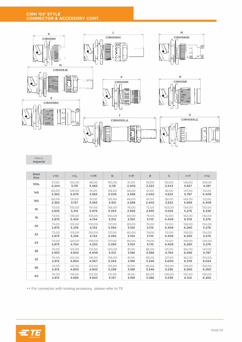
PAGE 54
Shell Size ++K ++L ++M N ++P R S ++T ++U
10SL 57,002.244
130,005.118
88,003.465
130,005.118
61,002.402
59,002.323
90,003.543
148,005.827
109,004.291
14S 60,002.362
129,005.079
91,003.583
128,005.039
66,002.598
61,002.402
92,003.622
147,005.787
112,004.409
16S 60,002.362
131,005.157
91,003.583
125,004.921
66,002.598
61,002.402
92,003.622
144,005.669
112,004.409
16 72,002.835
135,005.315
101,003.976
136,005.354
76,002.992
72,002.835
103,004.055
134,005.276
133,005.236
18 73,002.875
138,005.433
105,004.134
140,005.512
80,003.150
79,003.110
112,004.409
162,006.378
134,005.276
20 73,002.875
133,005.236
105,004.134
137,005.394
80,003.150
79,003.110
112,004.409
159,006.260
134,005.276
22 73,002.875
133,005.236
105,004.134
137,005.394
80,003.150
79,003.110
112,004.409
159,006.260
134,005.276
24 73,002.875
120,004.724
108,004.252
137,005.394
80,003.150
79,003.110
112,004.409
159,006.260
134,005.276
28 75,002.953
123,004.843
112,004.409
140,005.512
81,003.189
86,003.386
121,004.764
165,006.496
147,005.787
32 74,002.913
122,004.803
116,004.567
136,005.354
81,003.189
85,003.346
127,005.000
162,006.378
153,006.024
36 74,002.913
122,004.803
122,004.803
133,005.236
81,003.189
85,003.346
133,005.236
159,006.260
159,006.260
40 74,002.913
119,004.685
123,004.843
131,005.157
81,003.189
86,003.386
128,005.039
155,006.102
159,006.260
MetricImperial
CIRH ‘09’ STYLE CONNECTOR & ACCESSORY CONT.
++ For connector with locking accessory, please refer to TE
K
CIRH09H
N
CIRH09JE
S
CIRH09RC
P
CIRH09M
L
CIRH09HC
T
CIRH09XLA
U
CIRH09XLC
R
CIRH09R
M
CIRH09HD

RAIL /// CIRH: MODULAR BAYONET LOCK CONNECTOR
Shell Size A Max. C Max. d1
+0.2, -0 mmd2
Thread E Max. H Max. 0m Min. Overlap, mated
10SL 24,200.953
25,701.012
3.200.126 M4 3,00
0.11828,101.106
11,100.437
14S 30,601.205
30,301.193
3.200.126 M4 3,40
0.13428,101.106
11,100.437
16S 33,401.315
32,801.291
3.200.126 M4 3,40
0.13428,101.106
11,100.437
16 33,401.315
32,801.291
3.200.126 M4 3,40
0.13437,601.480
15,850.624
18 37,301.469
35,301.390
3.200.126 M4 4,20
0.16538,601.519
15,850.624
20 40,701.602
38,301.508
3.200.126 M4 4,20
0.16538,601.519
15,850.624
22 44,201.740
41,301.626
3.200.126 M4 4,20
0.16538,601.519
15,850.624
24 47,701.878
44,801.764
3.200.126 M4 4,20
0.16541,001.614
15,750.620
28 54,502.146
51,102.012
3.200.126 M5 4,20
0.16541,801.646
15,750.620
32 61,402.417
57,302.256
4,300.169 M5 4,20
0.16545,001.772
15,750.620
36 68,002.677
63,802.512
4,300.169 M5 4,20
0.16545,001.772
15,750.620
40 74,002.913
70,202.764
4,300.169 M5 4,20
0.16545,001.772
15,750.620
PANEL MOUNTED PLUG (NO ACCESSORY THREAD) STYLE: CIRH12A/CIRH12A...M6
MetricImperial
Note: No provision for rear sealing - contact factory if required. See page 90 for panel mounting details.
4 holes Ød1
C
C
H
E
ØA
4 Tapped Holes Ød2(M6 MOD.)
Om

PAGE 56
Shell Size
F Thread Dia. Class
2B
F1 Thread Dia. Class
2A
GMax
NMax
SMin
TMax
MMax
10SL 5/8" x 24 UNEF 3/4" x 20 UNEF 11,000.433
23.100.909
8,400.331
18,500.728
10.100.398
14S 3/4" x 20 UNEF 7/8" x 20 UNEF 10,000.394
27,601.087
8,510.335
21,530.848
11,710.461
16S 7/8" x 20 UNEF 1" x 20 UNEF 10,000.394
27,601.087
9,740.383
25,501.004
13,100.516
16 7/8" x 20 UNEF 1" x 20 UNEF 11,000.433
30,601.205
9,740.383
25,501.004
13,100.516
18 1" x 20 UNEF 1 2/16" x 18 UNEF 11,000.433
30,601.205
12,900.508
29,101.146
16,260.640
20 1 3/16" x 18 UNEF 1 7/16" x 18 UNEF 11,000.433
30,601.205
18,230.718
35,451.396
21,510.847
22 1 3/16" x 18 UNEF 1 7/16" x 18 UNEF 11,000.433
30,601.205
18,230.718
35,451.396
21,510.847
24 1 7/16" x 18 UNEF 1 3/4" x 18 UNS 11,000.433
30,601.205
25,931.021
43,601.717
29,211.150
28 1 7/16" x 18 UNEF 1 3/4" x 18 UNS 11,000.433
30,601.205
25,931.021
43,601.717
29,211.150
32 1 3/4" x 18 UNS 1 3/4" x 18 UNS 13,000.512
30,601.205
25,931.021
49,551.951
29,101.146
36 2" x 18 UNS 2" x 18 UNS 13,000.512
30,601.205
32,001.260
55,902.201
35,191.385
40 2 1/4" x 16 UN 2 1/4" x 16 UN 13,000.512
30,601.205
32,331.273
63,102.484
35,601.402
MetricImperial
How to order:
CIRB - ** - CRA
Shell size
CONDUIT ADAPTOR WITH BRAID SCREEN TRAP - NO GROMMET ACCESSORY TYPE ‘RM’ STYLE: CIRB - ** - CRA
Note: This accessory can only be used in conjunction with style ‘H’ or ‘FT’ adaptor.
*Please consult TE for availability.
ØT
ØFThread
ØS ØMØF1
Thread
G
N

RAIL /// CIRH: MODULAR BAYONET LOCK CONNECTOR
Shell Size
F Thread Dia. Class 2B
N1Max
N2Max
S Min/Max
T Max
Oa Min Overlap Accessory
10SL 5/8" x 24 UNEF 36,421.434
86,683.413
3,68/5,760.145/0.227
35,151.384
7,000.276
14S 3/4" x 20 UNEF 27,411.079
85,043.348
4,62/8,100.182/0.319
39,881.570
7,000.276
16S 7/8" x 20 UNEF 27,411.079
81,993.228
7,82/11,300.308/0.444
41,451.632
7,000.276
16 7/8" x 20 UNEF 27,411.079
81,993.228
7,82/11,300.308/0.444
41,451.632
7,000.276
18 1" x 20 UNEF 44,681.759
85,553.368
8,79/14,450.346/0.569
45,521.792
7,000.276
20 1 1/8" x 18 UNEF 44,681.759
84,613.331
10,54/16,000.415/0.632
49,631.954
7,000.276
22 1 1/4" x 18 UNEF 44,681.759
84,613.331
10,54/16,000.415/0.632
49,631.954
7,000.276
24 1 2/8" x 18 UNEF 44,681.759
79,203.118
14,55/19,230.573/0.757
56,292.216
7,000.276
28 1 5/8" x 18 UNEF 54,792.157
89,313.516
14,15/19,230.557/0.757
60,452.380
7,000.276
32 1 7/8" x 16 UN 54,792.157
86,133.390
19,18/23,980.755/0.944
68,432.694
7,000.276
36 2 1/16" x 16 UNS 54,792.157
82,983.267
24,51/31,930.965/1.257
71,682.822
7,000.276
NON-LOCKING CABLE CLAMP WITH GROMMET & FOLLOWER ACCESSORY TYPE ‘D’ STYLE: CIRBH - ** - ** - OCN - F80
MetricImperial
How to order:
CIRBH - ** - ** - OCN- F80
Shell size
Contact arrangement
ØT
ØF ØS
OaN1
N2

PAGE 58
Shell Size
T Max
F Thread Dia. Class
2B
N Max
S Min
Oa Min Overlap Accessory
10SL 21,600.850
5/8" x 24 UNEF 20,830.820
8,600.339
6,100.240
14S 24,800.976
3/4" x 20 UNEF 20,830.820
11,100.437
6,100.240
16S 28,701.130
7/8" x 20 UNEF 20,830.820
14,300.563
6,100.240
16 28,701.130
7/8" x 20 UNEF 25,531.005
14,300.563
7,600.300
18 31,901.256 1" x 20 UNEF 25,53
1.00516,700.657
7,600.300
20 34,901.374 1 1/8" x 18 UNEF 25,53
1.00519,800.780
7,600.300
22 38,201.504 1 1/4" x 18 UNEF 25,53
1.00521,340.840
7,600.300
24 41,401.630 1 3/8" x 18 UNEF 25,53
1.00525,401.000
7,600.300
28 47,801.882 1 5/8" x 18 UNEF 25,53
1.00530,131.186
7,600.300
32 54,102.130 1 7/8" x 16 UN 25,53
1.00536,731.446
7,600.300
36 58,702.311 2 1/16" x 16 UNS 25,53
1.00541,001.614
7,600.300
40 63.002.480 2 5/16" x 16 UN 25,64
1.00945,901.807
7,600.300
MetricImperial
NON-LOCKING GROMMET NUT TYPE ‘EV’ STYLE: CIRBH - ** - ** - EV - F80
How to order:
CIRBH - ** - ** - EV - F80
Shell size
Contact arrangement
ØT
ØF
ØS
N
Oa

RAIL /// CIRH: MODULAR BAYONET LOCK CONNECTOR
Shell Size
B Max
C Max
C1Max
F Thread Dia. Class
2B
N Max
T Max
T1Max
S Max
Oa Min Overlap
Accessory
10SL 24,000.945
30,001.181
100,003.937
5/8" x 24 UNEF 42,001.654
22,000.866
22,700.894
5,760.227
7,000.276
14S 25,000.984
30,001.181
100,003.937
3/4" x 20 UNEF 42,001.654
25,000.984
27,501.083
8,100.319
7,000.276
16S 27,001.063
30,001.181
100,003.937
7/8" x 20 UNEF 45,001.772
28,001.102
30,001.181
11,300.444
7,000.276
16 27,001.063
30,001.181
100,003.937
7/8" x 20 UNEF 45,001.772
28,001.102
30,001.181
11,300.444
7,000.276
18 30,101.224
35,001.378
100,003.937 1" x 20 UNEF 53,00
2.08731,001.220
33,001.299
14,450.569
7,000.276
20 33,001.299
35,001.378
100,003.937 1 1/8" x 18 UNEF 53,00
2.08735,001.378
37,501.476
16,000.632
7,000.276
22 33,101.303
35,001.378
100,003.937 1 1/4" x 18 UNEF 53,00
2.08738,001.496
37,501.476
16,000.632
7,000.276
24 37,901.492
40,001.575
100,003.937 1 3/8" x 18 UNEF 58,00
2.28341,001.614
43,301.705
19,230.757
7,000.276
28 37,101.461
40,001.575
100,003.937 1 5/8" x 18 UNEF 58,00
2.28348,001.890
43,301.705
19,230.757
7,000.276
32 43,101.697
45,001.772
110,004.331 1 7/8" x 16 UN 66,00
2.59854,002.126
51,702.035
23,980.944
7,000.276
36 45,901.807
50,001.969
110,004.331 2 1/16" x 16 UNS 69,00
2.71761,002.402
58,002.283
31,931.257
7,000.276
40 49,001.929
54,602.150
100,003.937 2 5/16" x 16 UN 85,50
3.36667,002.638
65,002.559
35,101.382
7,000.276
LOCKING 90° OUTLET WITH CABLE CLAMP & BUSHING TYPE ‘F’ STYLE: CIRBH - ** - ** - F - F80
MetricImperial
How to order:
CIRBH - ** - ** - F - F80
Shell size
Contact arrangement

PAGE 60
Shell Size
B Max
C Max
D Max
F Thread Dia. Class
2B
T Max
Oa Min Overlap
Accessory
10SL 24,000.945
23,800.937
61,002.402
5/8" x 24 UNEF 22,000.866
7,000.276
14S 25,000.984
26,971.062
61,002.402
3/4" x 20 UNEF 25,000.984
7,000.276
16S 27,001.063
30,181.188
61,002.402
7/8" x 20 UNEF 28,001.102
7,000.276
16 27,001.063
30,181.188
61,002.402
7/8" x 20 UNEF 28,001.102
7,000.276
18 30,101.224
33,321.312
68,002.677 1" x 20 UNEF 31,00
1.2207,00
0.276
20 33,001.299
39,671.562
68,002.677 1 1/8" x 18 UNEF 35,00
1.3787,00
0.276
22 33,101.303
39,671.562
68,002.677 1 1/4" x 18 UNEF 38,00
1.4967,00
0.276
24 37,901.492
44,451.750
76,002.992 1 3/8" x 18 UNEF 41,00
1.6147,00
0.276
28 37,101.461
44,451.750
76,002.992 1 5/8" x 18 UNEF 48,00
1.8907,00
0.276
32 43,101.697
57,152.250
87,003.425 1 7/8" x 16 UN 54,00
2.1267,00
0.276
36 45,901.807
60,332.375
98,003.858 2 1/16" x 16 UNS 61,00
2.4027,00
0.276
40 49,001.929
66,682.625
103,004.055 2 5/16" x 16 UN 67,00
2.6387,00
0.276
MetricImperial
LOCKING 90° OUTLET WITH SEALED CABLE CLAMP TYPE ‘FC’ STYLE: CIRBH - ** - ** - FC - F80
How to order:
CIRBH - ** - ** - FC - F80
Shell size
Contact arrangement

RAIL /// CIRH: MODULAR BAYONET LOCK CONNECTOR
Shell Size
B Max
C Max
F Thread Dia. Class
2B
F1Thread Dia.
Class 2A
T Max
Oa Min Overlap
Accessory
10SL 24,000.945
30,001.181
5/8" x 24 UNEF 5/8" x 24 UNEF 22,000.866
7,000.276
14S 25,000.984
30,001.181
3/4" x 20 UNEF 3/4" x 20 UNEF 25,000.984
7,000.276
16S 27,001.063
30,001.181
7/8" x 20 UNEF 7/8" x 20 UNEF 28,001.102
7,000.276
16 27,001.063
30,001.181
7/8" x 20 UNEF 7/8" x 20 UNEF 28,001.102
7,000.276
18 30,101.224
35,001.378 1" x 20 UNEF 1" x 20 UNEF 31,00
1.2207,00
0.276
20 33,101.299
35,001.378 1 1/8" x 18 UNEF 1 3/16" x 18 UNEF 35,00
1.3787,00
0.276
22 33,101.303
35,001.378 1 1/4" x 18 UNEF 1 3/16" x 18 UNEF 38,00
1.4967,00
0.276
24 37,901.492
40,001.575 1 3/8" x 18 UNEF 1 7/16" x 18 NEF 41,00
1.6147,00
0.276
28 37,101.461
40,001.575 1 5/8" x 18 UNEF 1 7/16" x 18 NEF 48,00
1.8907,00
0.276
32 43,101.697
45,001.772 1 7/8" x 16 UN 1 3/4" x 18 UNS 54,00
2.1267,00
0.276
36 45,901.807
50,001.969 2 1/16" x 16 UNS 2" x 18 UNS 61,00
2.4027,00
0.276
40 49,001.929
54,602.150 2 5/16" x 16 UN 2 1/4" x 16 UN 67,00
2.6387,00
0.276
LOCKING 90° OUTLET WITH GROMMET ACCESSORY TYPE ‘FT’ STYLE: CIRBH - ** - ** - FT - F80
MetricImperial
How to order:
CIRBH - ** - ** - FT - F80
Shell size
Contact arrangement
ØT
ØFThread
ØF1
C
0aB

PAGE 62
Shell Size
A Max
B Max
C Max
D Max
F Thread Dia. Class
2B
T Max
Oa Min Overlap
Accessory
10SL 15,900.626
24,000.945
30,001.181
7,770.306
5/8" x 24 UNEF 22,000.866
7,000.276
14S 19,100.764
25,000.984
30,001.181
10,360.408
3/4" x 20 UNEF 25,000.984
7,000.276
16S 22,300.878
27,001.063
30,001.181
13,010.512
7/8" x 20 UNEF 28,001.102
7,000.276
16 22,300.878
27,001.063
30,001.181
13,010.512
7/8" x 20 UNEF 28,001.102
7,000.276
18 25,501.004
30,101.224
35,001.378
15,140.596 1" x 20 UNEF 31,00
1.2207,00
0.276
20 30,201.189
33,001.299
35,001.378
18,100.713 1 1/8" x 18 UNEF 35,00
1.3787,00
0.276
22 30,201.189
33,101.303
35,001.378
21,620.851 1 1/4" x 18 UNEF 38,00
1.4967,00
0.276
24 36,601.441
37,901.492
40,001.575
25,100.988 1 3/8" x 18 UNEF 41,00
1.6147,00
0.276
28 36,601.441
37,101.461
40,001.575
30,381.196 1 5/8" x 18 UNEF 48,00
1.8907,00
0.276
32 44,501.752
43,101.697
45,001.772
36,481.436 1 7/8" x 16 UN 54,00
2.1267,00
0.276
36 50,902.004
45,901.807
50,001.969
40,671.601 2 1/16" x 16 UNS 61,00
2.4027,00
0.276
40 57,202.252
49,001.929
54,602.150
48,501.909 2 5/16" x 16 UN 67,00
2.6387,00
0.276
MetricImperial
LOCKING 90° OUTLET RFI SHIELDED WITH GROMMET ACCESSORY TYPE ‘FM’ STYLE: CIRBH - ** - ** - FM - F80
How to order:
CIRBH - ** - ** - FM - F80
Shell size
Contact arrangement
ØFThread
ØT ØD
ØA
C
0a
B

RAIL /// CIRH: MODULAR BAYONET LOCK CONNECTOR
Shell Size
F Thread Dia. Class
2B
G Max
M Max
N Max
S Min
T Max
Oa Min Overlap
Accessory
10SL 5/8" x 24 UNEF 8,200.323
15,700.618
28.461.120
7,700.303
22,000.87
7,000.276
14S 3/4" x 20 UNEF 8,200.323
19,300.760
28.461.120
10.600.417
25,000.99
7,000.276
16S 7/8" x 20 UNEF 8,200.323
24,100.949
28.461.120
13,500.532
28,001.11
7,000.276
16 7/8" x 20 UNEF 8,000.315
24,100.949
32.261.270
13,500.532
28,001.11
7,000.276
18 1" x 20 UNEF 8,000.315
24,100.949
32.261.270
14,600.575
31,001.22
7,000.276
20 1 1/8" x 18 UNEF 9,200.362
29,801.173
35.801.409
18,700.736
35,001.38
7,000.276
22 1 1/4" x 18 UNEF 9,200.362
29,801.173
35.801.409
20,800.819
38,001.50
7,000.276
24 1 3/8" x 18 UNEF 9,200.362
38,001.496
35.801.409
24,600.969
41,001.62
7,000.276
28 1 5/8" x 18 UNEF 9,200.362
38,001.496
35.761.408
27,001.063
48,001.89
7,000.276
32 1 7/8" x 16 UN 11,700.461
48,001.890
38.261.506
33,301.311
54,002.13
7,000.276
36 2 1/16" x 16 UNS 11,700.461
48,001.890
39.261.546
38,501.516
61,002.40
7,000.276
40 2 5/16" x 16 UN 12,100.476
57,952.281
38.301.508
48,101.894
67,002.638
7,000.276
LOCKING HEATSHRINK ADAPTOR WITH GROMMET ACCESSORY TYPE ‘G’ STYLE: CIRBH - ** - ** - HSA - F80
MetricImperial
How to order:
CIRBH - ** - ** - HSA - F80
Shell size
Contact arrangement
ØT
ØFThread
ØS
G
N
Oa
M

PAGE 64
Shell Size
F Thread Dia. Class
2B
G Max
M Max
N Max
S Min
T Max
Oa Min Overlap
Accessory
10SL 5/8" x 24 UNEF 12,400.488
15,700.618
32.261.270
8,600.339
22,000.87
7,000.276
14S 3/4" x 20 UNEF 12,400.488
19,300.760
32.261.270
11,100.437
25,000.984
7,000.276
16S 7/8" x 20 UNEF 12,400.488
24,100.949
32.261.270
14,300.563
28,001.102
7,000.276
16 7/8" x 20 UNEF 12,400.488
24,100.949
36.061.420
14,300.563
28,001.102
7,000.276
18 1" x 20 UNEF 12,400.488
24,100.949
36.061.420
16,700.657
31,001.22
7,000.276
20 1 1/8" x 18 UNEF 12,400.488
29,801.173
38.601.520
19,800.780
35,001.38
7,000.276
22 1 1/4" x 18 UNEF 12,400.488
29,801.173
38.601.520
21,340.840
38,001.50
7,000.276
24 1 3/8" x 18 UNEF 12,400.488
38,001.496
38.601.520
25,401.000
41,001.62
7,000.276
28 1 5/8" x 18 UNEF 12,400.488
38,001.496
38.561.518
30,131.186
48,001.89
7,000.276
32 1 7/8" x 16 UN 12,100.476
48,001.890
38.261.506
36,731.446
54,002.13
7,000.276
36 2 1/16" x 16 UNS 12,100.476
48,001.890
39.261.546
41,001.614
61,002.40
7,000.276
40 2 5/16" x 16 UN 12,100.476
57,952.281
38.301.508
48,101.894
67,002.638
7,000.276
MetricImperial
LOCKING RFI SHIELDED ADAPTOR WITH GROMMET ACCESSORY TYPE ‘GM’ STYLE: CIRBH - ** - ** - LHSA - F80
How to order:
CIRBH - ** - ** - LHSA - F80
Shell size
Contact arrangement
ØT
ØFThread ØS ØM
G
N
Oa

RAIL /// CIRH: MODULAR BAYONET LOCK CONNECTOR
Shell Size
F Thread Dia. Class
2B
M Max
G Max
N Max
S Min
T Max
Oa Min Overlap
Accessory
*10SL - - - - - - -
*14S - - - - - - -
*16S - - - - - - -
*16 - - - - - - -
18 1" x 20 UNEF 24,100.949
11,900.469
45,301.783
14,700.579
28,601.126
7,340.289
20 1 1/8" x 18 UNEF 29,801.173
11,900.469
51,102.012
18,700.736
31,851.254
7,340.289
22 1 1/4" x 18 UNEF 29,801.173
11,900.469
51,102.012
20,900.823
35,031.379
7,140.281
24 1 3/8" x 18 UNEF 38,001.496
11,900.469
51,102.012
24,700.972
39,101.539
7,140.281
28 1 5/8" x 18 UNEF 38,001.496
11,900.469
51,102.012
27,101.067
45,601.795
6,340.250
32 1 7/8" x 16 UN 48,001.890
11,900.469
51,102.012
33,401.315
50,802.000
7,400.291
36 2 1/16" x 16 UNS 48,001.890
11,900.469
51,102.012
38,601.520
57,452.262
7,400.291
40 2 5/16" x 16 UN 57,952.281
11,900.469
51,102.012
48,101.894
63,102.484
7,400.291
NON-LOCKING HEATSHRINK ADAPTOR, GROMMET & FOLLOWER ACCESSORY TYPE ‘GS’ STYLE: CIRBH - ** - ** - HSAS - F80
MetricImperial
* Please consult TE for availability.
How to order:
CIRBH - ** - ** - HSAS - F80
Shell size
Contact arrangement
ØT
ØMØFThread
G
N
Oa
ØS

PAGE 66
Shell Size
F Thread Dia. Class
2B
F1 Thread Dia. Class
2A
G Max
N Max
S Min
T Max
Oa Min Overlap
Accessory
10SL 5/8" x 24 UNEF 5/8" x 24 UNEF 9,500.374
27,901.098
8,200.323
22,000.87
7,000.276
14S 3/4" x 20 UNEF 3/4" x 20 UNEF 9,500.374
27,901.098
11,100.437
25,000.99
7,000.276
16S 7/8" x 20 UNEF 7/8" x 20 UNEF 9,500.374
27,901.098
14,300.563
28,001.11
7,000.276
16 7/8" x 20 UNEF 7/8" x 20 UNEF 9,500.374
27,901.098
14,300.563
28,001.11
7,000.276
18 1" x 20 UNEF 1" x 20 UNEF 9,500.374
29,901.177
16,700.657
31,001.22
7,000.276
20 1 1/8" x 18 UNEF 1 2/16" x 18 NEF 9,500.374
29,901.177
19,800.780
35,001.38
7,000.276
22 1 1/4" x 18 UNEF 1 3/16" x 18 NEF 9,500.374
29,901.177
19,800.780
38,001.50
7,000.276
24 1 3/8" x 18 UNEF 1 7/16" x 18 NEF 9,500.374
29,901.177
25,401.000
41,001.62
7,000.276
28 1 5/8" x 18 UNEF 1 7/16" x 18 NEF 9,500.374
30,001.181
27,001.063
48,001.89
7,000.276
32 1 7/8" x 16 UN 1 3/4" x 18 NS 11,000.433
28,901.138
32,501.280
54,002.13
7,000.276
36 2 1/16" x 16 UNS 2" x 18 NS 11,800.464
28,901.138
35,701.406
61,002.40
7,000.276
40 2 5/16" x 16 UN 2 1/4" x 16 UN 11,800.464
28,901.138
45,001.772
67,002.638
7,000.276
MetricImperial
LOCKING ARMOURED CONDUIT ADAPTOR WITH GROMMET ACCESSORY TYPE ‘H’ STYLE: CIRBH - ** - ** - ACA - F80
How to order:
CIRBH - ** - ** - ACA - F80
Shell size
Contact arrangement
ØT
ØF1Thread
ØFThread
G
N
Oa
ØS

RAIL /// CIRH: MODULAR BAYONET LOCK CONNECTOR
Shell Size
F Thread Dia. Class
2B
N1Max
N2Max S T
Max
Oa Min Overlap
Accessory
10SL 5/8" x 24 UNEF 40,101.58
100,103.94
5.590.220
22,700.90
7,000.276
14S 3/4" x 20 UNEF 41,701.65
96,703.81
7.920.312
27,501.09
7,000.276
16S 7/8" x 20 UNEF 43,501.72
98,503.88
11.100.437
30,001.19
7,000.276
16 7/8" x 20 UNEF 43,501.72
93,503.68
11.100.437
30,001.19
7,000.276
18 1" x 20 UNEF 50,001.97
95,003.74
14.270.562
33,001.30
7,000.276
20 1 1/8" x 18 UNEF 45,501.80
90,503.57
15.880.625
37,501.48
7,000.276
22 1 1/4" x 18 UNEF 45,501.80
90,503.57
15.880.625
37,501.48
7,000.276
24 1 3/8" x 18 UNEF 47,501.87
77,503.05
19.050.750
43,301.71
7,000.276
28 1 5/8" x 18 UNEF 47,601.88
77,603.06
19.050.750
43,301.71
7,000.276
32 1 7/8" x 16 UN 46,501.83
76,503.02
23.800.937
51,702.04
7,000.276
36 2 1/16" x 16 UNS 46,401.826
76,403.01
31.751.250
58,002.29
7,000.276
40 2 5/16" x 16 UN 59,802.35
73,802.90
34.921.375
65,002.56
7,000.276
LOCKING CABLE CLAMP WITH BUSHING TYPE ‘HC’ STYLE: CIRBH - ** - ** - HC - F80
MetricImperial
Note: Clamp & bush are available separately. See pages 83 & 84 respectively.
How to order:
CIRBH - ** - ** - HC - F80
Shell size
Contact arrangement
ØTØF
Thread
Oa
N1N2
ØS

PAGE 68
Shell Size
AMax B
C F Thread Dia. Class
2B
T Max
Oa Min Overlap
AccessoryMax Min
10SL 58,872.318
23,800.937
7,930.312
2,380.094
5/8" x 24 UNEF 22,000.866
7,000.276
14S 58,872.318
26,971.062
11,120.438
6,350.250
3/4" x 20 UNEF 25,000.984
7,000.276
16S 58,872.318
30,181.188
13,480.531
7,920.312
7/8" x 20 UNEF 28,000.984
7,000.276
16 58,872.318
30,181.188
13,480.531
7,920.312
7/8" x 20 UNEF 28,000.984
7,000.276
18 62,442.458
33,321.312
15,870.625
9,530.375 1" x 20 UNEF 31,00
1.2207,00
0.276
20 62,442.458
39,211.562
19,000.748
12,700.500 1 1/8" x 18 UNEF 35,00
1.3787,00
0.276
22 62,442.458
39,211.562
19,000.748
12,700.500 1 1/4" x 18 UNEF 38,00
1.4967,00
0.276
24 65,612.583
44,451.750
23,800.937
15,090.594 1 3/8" x 18 UNEF 41,00
1.6147,00
0.276
28 65,712.587
44,451.750
23,800.937
15,090.594 1 5/8" x 18 UNEF 48,00
1.8907,00
0.276
32 70,962.794
57,152.250
31,751.250
23,830.938 1 7/8" x 16 UN 54,00
2.1267,00
0.276
36 77,313.044
60,332.375
35,001.378
24,610.969 2 1/16" x 16 UNS 61,00
2.4027,00
0.276
40 77,313.044
66,682.625
41,251.624
30,181.188 2 5/16" x 16 UN 67,00
2.6387,00
0.276
MetricImperial
LOCKING SEALED CABLE CLAMP TYPE ‘HD’ STYLE: CIRBH - ** - ** - HD - F80
How to order:
CIRBH - ** - ** - HD - F80
Shell size
Contact arrangement
ØT
ØFThread
A
C B
Oa

RAIL /// CIRH: MODULAR BAYONET LOCK CONNECTOR
Shell Size
F Thread dia. Class
2B
L Max S T
Max
Oa Min Overlap
Accessory
10SL 5/8" x 24 UNEF 99,133.903
5.590.220
19,100.752
7,000.276
14S 3/4" x 20 UNEF 95,963.778
7.920.312
22,100.870
7,000.276
16S 7/8" x 20 UNEF 92,786.653
11.100.437
25,501.004
7,000.276
16 7/8" x 20 UNEF 94,283.712
11.100.437
25,501.004
7,000.276
18 1" x 20 UNEF 97,513.839
14.270.562
28,601.126
7,340.289
20 1 1/8" x 18 UNEF 94,333.714
15.880.625
31,851.254
7,340.289
22 1 1/4" x 18 UNEF 94,333.714
15.880.625
35,031.379
7,340.289
24 1 3/8" x 18 UNEF 94,013.701
19.050.750
39,101.539
7,140.281
28 1 5/8" x 18 UNEF 94,013.701
19.050.750
45,601.795
6,340.250
32 1 7/8" x 16 UN 90,833.576
23.800.937
50,802.000
7,400.291
36 2 1/16" x 16 UNS 87,673.452
31.751.250
57,452.262
7,400.291
40 2 5/16" x 16 UN 84,433.324
34.921.375
63,102.484
6,340.250
NON-LOCKING CABLE CLAMP WITH BUSHING TYPE ‘JE’ STYLE: CIRBH - ** - ** - JE - F80
MetricImperial
How to order:
CIRBH - ** - ** - JE - F80
Shell size
Contact arrangement
ØT
ØFThread
Oa
L
S

PAGE 70
Shell Size
F Thread Dia. Class
2B
MMax
NMax
SMin
TMax
Oa Min Overlap
Accessory
10SL 5/8" x 24 UNEF 19,000.748
31,300.812
8,600.339
22,000.87
7,000.276
14S 3/4" x 20 UNEF 22,500.886
33,901.335
10,600.417
25,000.99
7,000.276
16S 7/8" x 20 UNEF 25,501.004
33,901.335
13,500.532
28,001.11
7,000.276
16 7/8" x 20 UNEF 25,501.004
33,901.335
13,500.532
28,001.11
7,000.276
18 1" x 20 UNEF 25,501.004
36,901.453
14,600.575
31,001.22
7,000.276
20 1 1/8" x 18 UNEF 32,501.280
36,901.453
18,500.728
35,001.38
7,000.276
22 1 1/4" x 18 UNEF 34,501.358
36,901.453
20,800.819
38,001.50
7,000.276
24 1 3/8" x 18 UNEF 38,501.516
36,901.453
24,600.969
41,001.62
7,000.276
28 1 5/8" x 18 UNEF 41,501.634
35,901.413
27,001.063
48,001.89
7,000.276
32 1 7/8" x 16 UN 48,501.910
35,901.413
33,301.311
54,002.13
7,000.276
36 2 1/16" x 16 UNS 55,502.185
35,901.413
38,501.516
61,002.40
7,000.276
40 2 5/16" x 16 UN 62,502.461
35,901.413
45,001.772
67,002.638
7,000.276
MetricImperial
LOCKING SCREENED CABLE ADAPTOR TYPE ‘M’ STYLE: CIRBH - ** - ** - SCA - F80
How to order:
CIRBH - ** - ** - SCA - F80
Shell size
Contact arrangement
ØT
ØFThread
N
Oa
ØSØM

RAIL /// CIRH: MODULAR BAYONET LOCK CONNECTOR
Shell Size
F Thread Dia. Class
2B
F1Thread Dia.
Class 2A
G Max
N Max
S Min
T Max
Oa Min Overlap
Accessory
10SL 5/8" x 24 UNEF 5/8" x 24 UNEF 10,100.398
29,101.146
8,800.346
19,100.752
7,000.276
14S 3/4" x 20 UNEF 3/4" x 20 UNEF 10,100.398
29,101.146
11,300.445
22,100.870
7,000.276
16S 7/8" x 20 UNEF 7/8" x 20 UNEF 10,100.398
29,101.146
18,540.730
25,501.004
7,000.276
16 7/8" x 20 UNEF 7/8" x 20 UNEF 10,100.398
30,601.205
18,540.730
25,501.004
7,000.276
18 1" x 20 UNEF 1" x 20 UNEF 10,100.398
37,001.457
16,700.657
28,601.126
7,340.289
20 1 1/8" x 18 UNEF 1 3/16" x 18 UNEF 10,100.398
37,001.457
19,800.780
31,851.254
7,340.289
22 1 1/4" x 18 UNEF 1 3/16" x 18 UNEF 10,100.398
37,001.457
19,800.780
35,031.379
7,340.289
24 1 3/8" x 18 UNEF 1 7/16" x 18 UNEF 11,100.437
39,851.569
25,401.000
39,101.539
7,140.281
28 1 5/8" x 18 UNEF 1 7/16" x 18 UNEF 11,100.437
39,851.569
30,131.186
45,601.795
6,340.250
32 1 7/8" x 16 UN 1 3/4" x 18 UNS 11,100.437
39,851.569
32,501.280
50,802.000
7,400.291
36 2 1/16" x 16 UNS 2" x 18 UNS 11,100.437
39,851.569
35,701.406
57,452.262
7,400.291
40 2 5/16" x 16 UN 2 1/4" x 16 UN 11,100.437
39,851.569
45,001.772
63,102.484
6,340.250
NON-LOCKING CONDUIT ADAPTOR TYPE ‘R’ STYLE: CIRBH - ** - ** - CCA - F80
MetricImperial
How to order:
CIRBH - ** - ** - CCA - F80
Shell size
Contact arrangement
ØT
ØSØF1
Thread
ØFThread
Oa
N
G

PAGE 72
Shell Size
AMax B
C F Thread Dia. Class
2B
TMax
Oa Min Overlap
AccessoryMax Min
10SL 59,102.327
23,800.937
7,930.312
2,380.094
5/8" x 24 UNEF 19,100.752
7,000.276
14S 59,102.327
26,971.062
11,120.438
6,350.250
3/4" x 20 UNEF 22,100.870
7,000.276
16S 59,102.327
30,181.188
13,480.531
7,920.312
7/8" x 20 UNEF 25,501.004
7,000.276
16 60,602.386
30,181.188
13,480.531
7,920.312
7/8" x 20 UNEF 25,501.004
7,000.276
18 70,002.756
33,321.312
15,870.625
9,530.375 1" x 20 UNEF 28,60
1.1267,34
0.289
20 70,002.756
39,211.562
19,000.748
12,700.500 1 1/8" x 18 UNEF 31,85
1.2547,34
0.289
22 70,002.756
39,211.562
19,000.748
12,700.500 1 1/4" x 18 UNEF 35,03
1.3797,34
0.289
24 75,852.986
44,451.750
23,800.937
15,090.594 1 3/8" x 18 UNEF 39,10
1.5397,14
0.281
28 75,852.986
44,451.750
23,800.937
15,090.594 1 5/8" x 18 UNEF 45,60
1.7956.34
0.250
32 81,853.222
57,152.250
31,751.250
23,830.938 1 7/8" x 16 UN 50,80
2.0007,400.291
36 88,853.498
60,332.375
35,001.378
24,610.969 2 1/16" x 16 UNS 57,45
2.2627,400.291
40 88,853.498
66,682.625
41,251.624
30,181.188 2 5/16" x 16 UN 63,10
2.4846.34
0.250
MetricImperial
NON-LOCKING SEALED CABLE CLAMP TYPE ‘RC’ STYLE: CIRBH - ** - ** - RC - F80
How to order:
CIRBH - ** - ** - RC - F80
Shell size
Contact arrangement

RAIL /// CIRH: MODULAR BAYONET LOCK CONNECTOR
Shell Size C
F Thread Dia. Class
2BN T
MaxT1
Max
Oa Min Overlap
Accessory
10SL 5,590.220
5/8" x 24 UNEF 118,354.659
22,000.866
22,700.894
7,000.276
14S 7,920.312
3/4" x 20 UNEF 115,184.535
25,000.984
27,501.083
7,000.276
16S 11,100.437
7/8" x 20 UNEF 112,004.409
28,001.102
30,001.181
7,000.276
16 11,100.437
7/8" x 20 UNEF 122,304.815
28,001.102
30,001.181
7,000.276
18 14,270.562 1" x 20 UNEF 119,13
4.69031,001.220
33,001.299
7,000.276
20 15,880.625 1 1/8" x 18 UNEF 115,95
4.56535,001.378
37,501.476
7,000.276
22 15,880.625 1 1/4" x 18 UNEF 115,95
4.56538,001.496
37,501.476
7,000.276
24 19,050.750 1 3/8" x 18 UNEF 112,78
4.44041,001.614
43,301.704
7,000.276
28 19,050.750 1 5/8" x 18 UNEF 119,78
4.71648,001.889
43,301.704
7,000.276
32 23,800.937 1 7/8" x 16 UN 116,60
4.59154,002.126
51,702.035
7,000.276
36 31,751.250 2 1/16" x 16 UNS 113,43
4.46661,002.402
58,002.283
7,000.276
40 34,921.375 2 5/16" x 16 UN 110,20
4.33867,002.638
65,002.559
7,000.276
LONG BACKSHELL WITH CABLE CLAMP & BUSHING TYPE ‘XLA’ STYLE: CIRBH - ** - ** - XLA - F80
MetricImperial
N
OaØ T
Ø F
Thr
ead
Ø C
Ø T
1
How to order:
CIRBH - ** - ** - XLA - F80
Shell size
Contact arrangement

PAGE 74
Shell Size
C F Thread Dia. Class
2BN T
MaxT1
Max
Oa Min Overlap
AccessoryMax Min
10SL 7,930.312
2,380.094
5/8" x 24 UNEF 79,473.129
22,000.866
23,800.937
7,000.276
14S 11,120.438
6,350.250
3/4" x 20 UNEF 79,473.129
25,000.984
26,971.062
7,000.276
16S 13,480.531
7,920.312
7/8" x 20 UNEF 79,473.129
28,001.102
30,181.188
7,000.276
16 13,480.531
7,920.312
7/8" x 20 UNEF 91,333.596
28,001.102
30,181.188
7,000.276
18 15,870.625
9,530.375 1" x 20 UNEF 91,33
3.59631,001.220
33,321.312
7,000.276
20 19,000.748
12,700.500 1 1/8" x 18 UNEF 91,33
3.59635,001.378
39,671.562
7,000.276
22 19,000.748
12,700.500 1 1/4" x 18 UNEF 91,33
3.59638,001.496
39,671.562
7,000.276
24 23,800.937
15,090.594 1 3/8" x 18 UNEF 94,51
3.72141,001.614
44,451.750
7,000.276
28 23,800.937
15,090.594 1 5/8" x 18 UNEF 101,51
3.99648,001.889
44,451.750
7,000.276
32 31,751.250
23,830.938 1 7/8" x 16 UN 107,86
4.24654,002.126
57,152.250
7,000.276
36 35,001.378
24,610.969 2 1/16" x 16 UNS 114,21
4.49661,002.402
60,332.375
7,000.276
40 41,251.624
30,181.188 2 5/16" x 16 UN 114,21
4.49667,002.638
66,682.625
7,000.276
MetricImperial
LONG BACKSHELL WITH SEALED CABLE CLAMP TYPE ‘XLC’ STYLE: CIRBH - ** - ** - XLC - F80
N
OaØ T
Ø F
Thr
ead
Ø C
Ø T
1
How to order:
CIRBH - ** - ** - XLC - F80
Shell size
Contact arrangement

RAIL /// CIRH: MODULAR BAYONET LOCK CONNECTOR
Shell Size
Ø T (Max.) B C
±0.10ØD
±0/-0.10 Ø E Thd. Ø F Thd. 0a(Min)
10SL 22,00.866
48,51.909
15,00.591
8,50.335
5/8" x 24 UNEF 5/8" x 24 UNEF 7,00.276
14S 25,00.984
48,51.909
15,00.591
11,70.461
3/4" x 20 UNEF 3/4" x 20 UNEF 7,00.276
16S 28,01.102
48,51.909
15,00.591
13,90.547
7/8" x 20 UNEF 7/8" x 20 UNEF 7,00.276
16 28,01.103
58,82.303
15,00.591
13,90.547
7/8" x 20 UNEF 7/8" x 20 UNEF 7,00.276
18 31,01.220
58,82.303
15,00.591
16,90.666 1" x 20 UNEF 1" x 20 UNEF 7,0
0.276
20 35,01.378
58,82.303
15,00.591
20,90.823 1 3/16" x 18 UNEF 1 1/8" x 18 UNEF 7,0
0.276
22 38,01.496
58,82.303
15,00.591
20,90.823 1 3/16" x 18 UNEF 1 1/4" x 18 UNEF 7,0
0.276
24 41,01.614
58,82.303
15,00.591
25,91.020 1 7/16" x 18 UNEF 1 3/8" x 18 UNEF 7,0
0.276
28 48,01.890
65,82.303
15,00.591
25,91.020 1 7/16" x 18 UNEF 1 5/8" x 18 UNEF 7,0
0.276
32 54,02.126
65,82.303
15,00.591
32,01.260 1 3/4" x 18 UNS 1 7/8" x 16 UN 7,0
0.276
36 61,02.402
65,82.303
15,00.591
36,91.453 2" x 18 UNS 2 1/16" x 16 UNS 7,0
0.276
40 67,02.638
65,82.303
15,00.591
44,91.768 2 1/4" x 16 UN 2 5/16" x 16 UN 7,0
0.276
LONG BACKSHELL WITH GROMMET TYPE ‘SHE’ STYLE: CIRBH - ** - ** - SHE - F80
MetricImperial
How to order:
CIRBH - ** - ** - SHE - F80
Shell size
Contact arrangement
ØT
ØF
Thre
ad
ØD
ØE
Thd.
Oa
B
C

PAGE 76
Shell Size Thread F ØA max. B
ØD+0/-0.10
boreThread E
ØG Thread
Metric PG
10SL Consult TE
14S Consult TE
16S Consult TE
16 Consult TE
18 1" x 20 UNEF 31.0 58.8 16.7 1 3/16" x 18 UNEF M25 x 1.5 PG 16
20 1 1/8" x 18 UNEF 35.0 58.8 19.8 1 7/16" x 18 UNEF M32 x 1.5 PG 21
22 1 1/4" x 18 UNEF 38.0 58.8 19.8 1 7/16" x 18 UNEF M32 x 1.5 PG 21
24 1 3/8" x 18 UNEF 41.0 58.8 25.4 1 3/4" x 18 UNEF M40 x 1.5 PG 29
28 1 5/8" x 18 UNEF 48.0 65.8 27.0 1 3/4" x 18 UN M40 x 1.5 PG 29
32 1 7/8" x 16 UNEF 54.0 65.8 32.5 2" x 18 UNS M40 x 1.5 PG 29
36 2 1/16" x 16 UNS 61.0 65.8 35.7 2 1/4" x 16 UN M50 x 1.5 PG 36
40 2 5/16" x 16 UNS 67.0 65.8 45.0 2 1/2" x 16 UN M50 x 1.5 PG 42
STEP-UP ADAPTOR - TYPE ‘SUAM/SUAP’ STYLE: CIRBH - ** - ** - SUA* - F80
Ø A
B
12.00
15.00
Ø F
Thr
ead
Ø G
Thr
ead
Ø E
Thr
ead
Ø D
* Indicates: M = Metric / P = PG
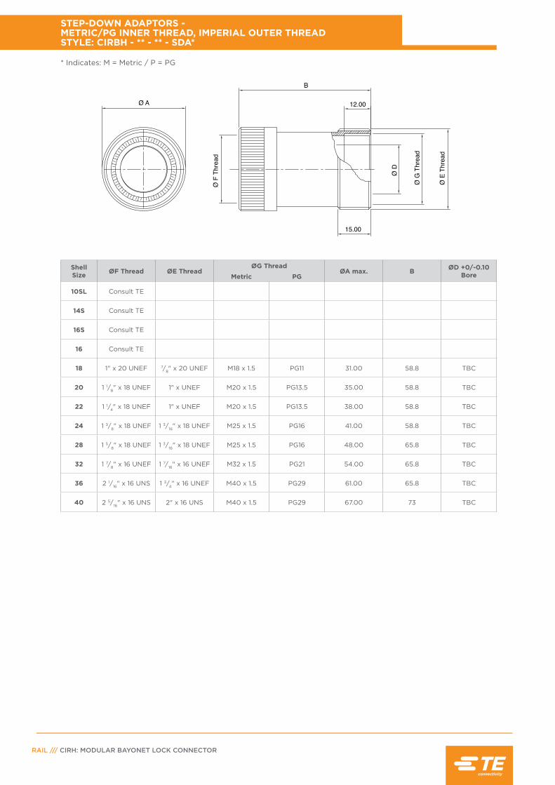
RAIL /// CIRH: MODULAR BAYONET LOCK CONNECTOR
Shell Size ØF Thread ØE Thread
ØG ThreadØA max. B ØD +0/-0.10
BoreMetric PG
10SL Consult TE
14S Consult TE
16S Consult TE
16 Consult TE
18 1" x 20 UNEF 7/8" x 20 UNEF M18 x 1.5 PG11 31.00 58.8 TBC
20 1 1/8" x 18 UNEF 1" x UNEF M20 x 1.5 PG13.5 35.00 58.8 TBC
22 1 1/4" x 18 UNEF 1" x UNEF M20 x 1.5 PG13.5 38.00 58.8 TBC
24 1 3/8" x 18 UNEF 1 3/16" x 18 UNEF M25 x 1.5 PG16 41.00 58.8 TBC
28 1 5/8" x 18 UNEF 1 3/16" x 18 UNEF M25 x 1.5 PG16 48.00 65.8 TBC
32 1 7/8" x 16 UNEF 1 7/16" x 16 UNEF M32 x 1.5 PG21 54.00 65.8 TBC
36 2 1/16" x 16 UNS 1 3/4" x 16 UNEF M40 x 1.5 PG29 61.00 65.8 TBC
40 2 5/16" x 16 UNS 2" x 16 UNS M40 x 1.5 PG29 67.00 73 TBC
STEP-DOWN ADAPTORS - METRIC/PG INNER THREAD, IMPERIAL OUTER THREAD STYLE: CIRBH - ** - ** - SDA*
Ø A
B
12.00
15.00
Ø F
Thr
ead
Ø G
Thr
ead
Ø E
Thr
ead
Ø D
* Indicates: M = Metric / P = PG

PAGE 78
Shell Size ØF Thread ØE Thread
ØG ThreadØA max. B
Metric PG
10SL Consult TE
14S Consult TE
16S Consult TE
16 Consult TE
18 1" x 20 UNEF 1 3/16" x 18 UNEF M25 x 1.5 PG16 31.00 83.3
20 1 1/8" x 18 UNEF 1 7/16" x 18 UNEF M32 x 1.5 PG21 35.00 83.3
22 1 1/4" x 18 UNEF 1 7/16" x 18 UNEF M32 x 1.5 PG21 38.00 83.3
24 1 3/8" x 18 UNEF 1 3/4" x 18 UNEF M40 x 1.5 PG29 41.00 83.3
28 1 5/8" x 18 UNEF 1 3/4" x 18 UN M40 x 1.5 PG29 48.00 83.3
32 1 7/8" x 16 UNEF 2" x 18 UNS M40 x 1.5 PG29 54.00 83.3
36 2 1/16" x 16 UNS 2 1/4" x 16 UN M50 x 1.5 PG36 61.00 83.3
40 2 5/16" x 16 UNS 2 1/2" x 16 UN M50 x 1.5 PG42 67.00 83.3
SCREENED SHELL EXTENDER - METRIC/PG INNER THREAD, IMPERIAL OUTER THREAD STYLE: CIRBH - ** - ** - SUA*S
* Indicates: M = Metric / P = PG

RAIL /// CIRH: MODULAR BAYONET LOCK CONNECTOR
Shell Size
Part Number ØA B Thread
C
10SL CIRB-10SL-#GA-#M32 20.00 35.00 5/8" x 24 UNEF
14S CIRB-14S-#GA-#M32 23.50 35.00 3/4" x 20 UNEF
16S CIRB-16S-#GA-#M32 28.00 35.00 7/8" x 20 UNEF
18 CIRB-18-#GA-#M32 34.00 40.00 1" x 20 UNEF
20-22 CIRB-20-#GA-#M32 37.00 35.001 3/16" x 18 UNEF
20-22 CIRB-20-#GA-#M32
43.00 40.0024-28 CIRB-24-#GA-#M32
1 7/16" x 18 UNEF24-28 CIRB-24-#GA-#M32
24-28 CIRB-24-#GA-#M3254.00
46.00
32 CIRB-32-#GA-#M32 38.00 1 3/4" x 18 UNS
36 CIRB-36-#GA-#M32 57.20 50.00 2" x 18 UNS
40 CIRB-40-#GA-#M32 65.00 51.00 2 1/4" x 16 UN
Thread Table (D)Imperial(PGA) Thread Size Metric
(MGA) Thread Size
A PG7 A M12
B PG9 B M16
C PG11 C M20
D PG13.5 D M25
E PG16 E M32
F PG21 F M40
G PG29 G M50
H PG36 H M63
J PG42
K PG48
PG THREADED ADAPTORS (FITTING ON ACA, CCA, XL & FT ACCESSORY WITH PG/METRIC THREAD)
Part Number KeyCIRB ## #GA #
P/N Prefi xAccessory Size
Thread DesignationPGA - ImperialM GA - Metric
P/N Example to fi t shell size 20 with arear metric thread size M25
CIRB 20 M GA D
Thread ‘D’(see table)
B
THR
EAD
C‘O’RING SEAL
THR
EAD
D
ØA
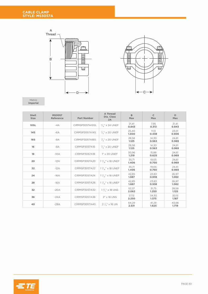
PAGE 80
Shell Size
MS3057Reference
Part Number
A Thread Dia. Class
2A
BMax
CMax
DMax
10SL -4A CIRMSP3057A10SL 5/8" x 24 UNEF 21,410.843
7,950.313
21,410.843
14S -6A CIRMSP3057A14S 3/4" x 20 UNEF 25,401.000
11,130.438
23,010.906
16S -8A CIRMSP3057A16S 7/8" x 20 UNEF 28,581.125
14,300.563
24,610.969
16 -8A CIRMSP3057A16 7/8" x 20 UNEF 28,581.125
14,300.563
24,610.969
18 -10A CIRMSP3057A18 1" x 20 UNEF 30,961.219
15,880.625
24,610.969
20 -12A CIRMSP3057A20 1 3/16" x 18 UNEF 35,711.406
19,050.750
24,610.969
22 -12A CIRMSP3057A22 1 3/16" x 18 UNEF 35,711.406
19,050.750
24,610.969
24 -16A CIRMSP3057A24 1 7/16" x 18 UNEF 42,851.687
23,830.938
26,971.062
28 -16A CIRMSP3057A28 1 7/16" x 18 UNEF 42,851.687
23,830.938
26,971.062
32 -20A CIRMSP3057A32 1 3/4" x 18 UNS 52,372.062
31,751.250
28,581.125
36 -24A CIRMSP3057A36 2" x 18 UNS 57,152.250
34,931.375
30,151.187
40 -28A CIRMSP3057A40 2 1/4" x 16 UN 64,292.531
41,281.625
43,661.719
CABLE CLAMP STYLE: MS3057A
MetricImperial
CD
B
AThread

RAIL /// CIRH: MODULAR BAYONET LOCK CONNECTOR
Shell Size
MS3057Reference
Part Number
A Thread Dia. Class
2A
C Dia. DMax
EMaxMax Min
10SL -4C CIRMSP3057C10SL 5/8" x 24 UNEF 7,930.312
2,380.094
34,931.375
23,800.937
14S -6C CIRMSP3057C14S 3/4" x 20 UNEF 11,120.438
6,350.250
34,931.375
26,971.062
16S -8C CIRMSP3057C16S 7/8" x 20 UNEF 13,480.531
7,920.312
34,931.375
30,181.188
16 -8C CIRMSP3057C16 7/8" x 20 UNEF 13,480.531
7,920.312
34,931.375
30,181.188
18 -10C CIRMSP3057C18 1" x 20 UNEF 15,870.625
9,530.375
36,501.437
33,321.312
20 -12C CIRMSP3057C20 1 3/16" x 18 UNEF 19,000.748
12,700.500
36,501.437
39,211.562
22 -12C CIRMSP3057C22 1 3/16" x 18 UNEF 19,000.748
12,700.500
36,501.437
39,211.562
24 -16C CIRMSP3057C24 1 7/16" x 18 UNEF 23,800.937
15,090.594
39,671.562
44,451.750
28 -16C CIRMSP3057C28 1 7/16" x 18 UNEF 23,800.937
15,090.594
39,671.562
44,451.750
32 -20C CIRMSP3057C32 1 3/4" x 18 UNS 31,751.250
23,830.938
46,021.812
57,152.250
36 -24C CIRMSP3057C36 2" x 18 UNS 35,001.378
24,610.969
52,372.062
60,332.375
40 -28C CIRMSP3057C40 2 1/4" x 16 UN 41,251.624
30,181.188
52,372.062
66,682.625
SEALED CABLE CLAMP FOR JACKETED CABLE STYLE: MS3057C
MetricImperial
AThread
D
E C Dia

PAGE 82
Shell Size
PartNumber A B C D
10SL CIRSBMSH5541 12,830.505
69,852.750
5,590.220
7,620.300
14S CIRSBMSH5542 15,880.625
66,682.625
7,920.312
10,800.425
16S CIRSBMSH5543 19,050.750
63,502.500
11,100.437
13,970.550
16 CIRSBMSH5543 19,050.750
63,502.500
11,100.437
13,970.550
18 CIRSBMSH5544 22,230.875
60,332.375
14,270.562
15,570.613
20 CIRSBMSH5545 25,401.000
57,152.250
15,880.625
18,750.738
22 CIRSBMSH5546 28,581.125
57,152.250
15,880.625
18,750.738
24 CIRSBMSH5547 31,751.250
53,982.125
19,050.750
23,500.925
28 CIRSBMSH5548 38,231.505
53,982.125
19,050.750
23,500.925
32 CIRSBMSH5549 44,451.750
50,802.000
23,800.937
31,451.238
36 CIRSBMSH55410 47,881.885
47,631.875
31,751.250
34,621.363
40 CIRSBMSH55411 52,902.083
44,401.748
34,921.375
40,991.614
TELESCOPIC BUSHINGSTYLE: MS 3057A
MetricImperial
Note: The bushings can fit inside one another to reduce the cable entry diameter and improving clamping and sealing.
C
A
B
D

RAIL /// CIRH: MODULAR BAYONET LOCK CONNECTOR
Shell Size
A Min
B Nominal
B1Nominal
dMin
T Nominal
10SL 25,401.000
15,880.625
18,300.720
3,430.135
1,000.040
14S 30,201.188
19,000.750
24,700.972
3,430.135
1,000.040
16S 32,501.280
22,200.875
27,501.083
3,430.135
1,000.040
16 32,501.280
22,200.875
27,501.083
3,430.135
1,000.040
18 34,901.375
25,401.000
30,901.217
3,430.135
1,000.040
20 38,101.500
28,601.125
34,301.350
3,430.135
1,000.040
22 41,301.625
31,701.250
37,501.476
3,430.135
1,000.040
24 44,501.750
34,901.375
41,001.614
4,120.162
1,000.040
28 50,802.000
41,301.625
46,801.843
4,120.162
1,000.040
32 57,202.250
47,601.875
53,502.106
4,780.188
1,000.040
36 63,502.500
52,602.071
59,702.350
4,780.188
1,000.040
40 69,902.750
61,902.440
65,502.580
5,102.010
1,000.040
*49 110,004.331
98,103.862
98,103.862
7,900.311
1,250.049
PANEL SEALING GASKETS NON-SCREENING, SEALING ONLY RFI CONDUCTIVE SCREENING & SEALING
MetricImperial
*Size 49 is available as non-screened version only.
Front Mounted ReceptaclePart Number:
Non-Screening- CIRSB - ** - RPGRFI Screening- CIRSB - ** - RPGS
Rear Mounted ReceptaclePart Number:
Non-Screening- CIRSB - ** - FPGRFI Screening- CIRSB - ** - FPGS
T 4 Holes Ød
ØB A SQ.
T 4 Holes Ød
ØB1 A SQ.

PAGE 84
Shell Size
BMax
CMax
DMax
E1Max
E2Max
F1Max
F2Max
L approx.
See note
d1Min
d2+0.5, -0
+0.02, -0
Om Min Overlap Mated
10SL 22,800.898
26,101.028
18,200.717
17,500.689
21,600.850
24,600.969
28,401.118
100,004.000
4,850.191
4,300.169
11,100.437
14S 29,201.150
32,501.280
24,600.969
17,500.689
21,600.850
24,600.969
28,401.118
100,004.000
4,850.191
4,300.169
11,100.437
16S 32,401.276
35,301.390
27,401.079
17,500.689
21,600.850
24,600.969
28,401.118
100,004.000
4,850.191
4,300.169
11,100.437
16 32,401.276
35,301.390
27,401.079
24,000.945
27,301.075
24,600.969
28,401.118
100,004.000
4,850.191
4,300.169
15,850.624
18 36,501.437
38,701.524
30,801.213
24,000.945
27,301.075
29,801.173
33,901.335
150,006.000
4,850.191
4,300.169
15,850.624
20 39,901.571
42,101.658
34,201.346
24,000.945
27,301.075
29,801.173
33,901.335
150,006.000
4,850.191
4,300.169
15,850.624
22 43,101.697
45,301.784
37,401.472
24,000.945
27,301.075
29,801.173
33,901.335
150,006.000
4,850.191
4,300.169
15,750.620
24 46,601.835
48,801.921
40.901.610
24,000.945
27,301.075
29,801.173
33,901.335
150,006.000
4,850.191
4,300.169
15,750.620
28 53,402.102
54,602.150
46,701.838
24,000.945
27,301.075
29,801.173
33,901.335
150,006.000
4,850.191
4,300.169
15,750.620
32 60,102.366
61,302.413
53,402.102
27,001.063
27,301.075
29,801.173
33,901.335
150,006.000
4,850.191
5,500.217
15,750.620
36 66,302.610
67,502.658
59,602.346
27,001.063
27,301.075
29,801.173
33,901.335
150,006.000
4,850.191
5,500.217
15,750.620
40 72,102.838
73,402.890
65.502.579
27,001.063
27,301.075
29,801.173
33,901.335
150,006.000
4,850.191
5,500.217
15,750.620
PROTECTIVE CAPS STYLES: CIRBE - ** - X-PCA/X-PCAK & X-PCAJ/X-PCAJK TEB - ** - E-PAC/E-PCAK
MetricImperial
Note: For alternative cord or chain length, please consult TE.
CIRBE-**-X-PCAJK (with sash chain)
CIRB-**-E-PCA (with nylon cord)
CIRBE-**-X-PCA (with nylon cord)
CIRBE-**-X-PCAK (with sash chain)
CIRBE-**-X-PCAJ (with nylon cord)
CIRB-**-E-PCAK (with sash chain)
Caps for Single HoleMounting Receptacle
ØB
Ød1
0mE1
F1 ABBE - **-X-PCA(with nylon cord)
L
ABBE - **-X-PCAK(with sash chain)
Ød2
L
ØB
0mE1
F1 ABBE - **-X-PCAJ(with nylon cord)
L
ABBE - **-X-PCJaK(with sash chain)
L
ØDØd1
0mE2
F2
ABB - **-E-PCA(with nylon cord)
L
ØC
ABB - **-E-PCAK(with sash chain)
Ød2
L

RAIL /// CIRH: MODULAR BAYONET LOCK CONNECTOR
F80 Contact SizesAWG (Metric)
*Wire InsulationMin O/D
*Wire InsulationMax O/D
16S/16 (15S/15) 1,520.060
3,200.126
12 (25) 2,440.096
5,120.202
8 (100) 4,900.193
7,200.283
4 (160) 8.180.322
11,000.433
**0 (500) 14,000.551
16,000.630
Contact SizeAWG (Metric)
L Max
dMax
L1Max
d1Max
ColourCode
***16 (15) 12,300.484
3,900.154
20,000.787
3,200.126
Brown(KDP/KDS)
12 (25) 12,300.484
4,800.189
20,400.803
4,800.189 Orange
8 (100) 12,100.476
7,000.276
22,750.896
7,800.307 Violet
4 (160) 12,100.476
10,200.402 * * Black
0 (500) 12,500.500
15,600.614
24,600.969
15,000.590 White
INDIVIDUAL WIRE SEAL GROMMET DUMMY PIN, SOCKET & GROMMET FILLER PLUG
MetricImperial
MetricImperial
* Please contact sales office for further detail.** For details of grommet reducing bushes to suit 35mm2, 25mm2 & 16mm2 wire, please contact the sales office.
* Please consult TE for availability.*** For Grommet Filler Plugs (KFP), do not add F80 to part number. Colour Blue.
How to order:
CIRBH - ** - ** - GAC - F80
Shell size
Contact arrangement
Grommet Filler Plug Dummy ContactØd
L
Ød1
L1Ød
L
Ød1
L1
CIRB-**-KFP F80 CIRB-**-KDP F80

PAGE 86
PartNumber
BMax
CMax
D1Min
d2Thread
E Max X
Om min overlap mated
CIR-10SL-SX 17,600.693
25,701.012
3,200.126 M4 3,00
0.11818,200.717
11,100.437
CIR-14S-SX 18,000.709
30,301.193
3,200.126 M4 3,40
0.13423,100.909
11,100.437
CIR-16S-SX 18,000.709
32,801.291
3,200.126 M4 3,40
0.13424,600.969
11,100.437
CIR-16-SX 22,800.898
32,801.291
3,200.126 M4 3,40
0.13424,600.969
15,850.624
CIR-18-SX 23,600.929
35,301.390
3,200.126 M4 4,20
0.16527,001.063
15,850.624
CIR-20-SX 23,600.929
38,301.508
3,200.126 M4 4,20
0.16529,401.157
15,850.624
CIR-22-SX 23,600.929
41,301.626
3,200.126 M4 4,20
0.16531,801.252
15,750.620
CIR-24-SX 25,200.992
44,801.764
3.700.146 M4 4,20
0.16534,901.374
15,750.620
CIR-28-SX 25,200.992
51,102.012
3,700.146 M5 4,20
0.16539,701.563
15,750.620
CIR-32-SX 26,801.055
57,302.256
4,300.169 M5 4,20
0.16544,501.752
15,750.620
CIR-36-SX 26,801.055
63,802.512
4,300.169 M5 4,20
0.16549,201.937
15,750.620
CIR-40-SX 26,801.055
70,202.763
4,300.169 M5 4,20
0.16555,502.185
15,750.620
CIR-49-SX 56,732.233
110,404.346
8,500.335 - 8,20
0.32390,003.543
SQUARE FLANGE STOWAGE RECEPTACLE STYLE: CIR - ** - SX/SX - M6
MetricImperial
Note: See page 90 for mounting details • This part has a hole through the centre • In order to maintain sealing to a panel (when used with Gasket),
the panel cut out should not include the connector through hole• Not normally practical with tapped holes.
4 Holes Ø d1
C X
X
C
4 Tapped Holes d2
(M6 MOD.)
OmE
B
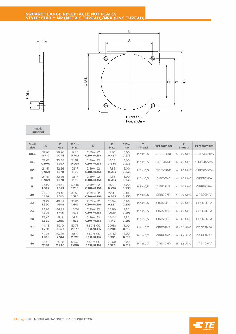
RAIL /// CIRH: MODULAR BAYONET LOCK CONNECTOR
Shell Size A B
MaxC Dia. Max D E
MaxF Dia. Max
TThread Part Number T
Thread Part Number
10SL 18,260.719
26,261.034
17,850.702
2,69/4,220.106/0.166
11,500.453
6,000.236 M3 x 0,5 CIRB10SLNP 4 - 40 UNC CIRB10SLNPA
14S 23,010.906
30,661.207
24,590.968
2,69/4,220.106/0.166
16,250.640
6,000.236 M3 x 0,5 CIRB14SNP 4 - 40 UNC CIRB14SNPA
16S 24,610.969
32,261.270
28,171.109
2,69/4,220.106/0.166
17,850.703
6,000.236 M3 x 0,5 CIRB16SNP 4 - 40 UNC CIRB16SNPA
16 24,610.969
32,261.270
28,171.109
2,69/4,220.106/0.166
17,850.703
6,000.236 M3 x 0,5 CIRB16NP 4 - 40 UNC CIRB16NPA
18 26,971.062
34,621.363
30,481.250
2,69/4,220.106/0.166
20,210.796
6,000.236 M3 x 0,5 CIRB18NP 4 - 40 UNC CIRB18NPA
20 29,361.156
38,481.515
33,531.320
2,69/4,220.106/0.166
22,470.885
6,000.236 M3 x 0,5 CIRB20NP 4 - 40 UNC CIRB20NPA
22 31,751.250
40,841.608
36,651.443
2,69/4,220.106/0.166
23,540.927
6,000.236 M3 x 0,5 CIRB22NP 4 - 40 UNC CIRB22NPA
24 34,931.375
44,831.765
40,001.575
2,69/4,220.106/0.166
25,901.020
7,500.295 M3 x 0,5 CIRB24NP 4 - 40 UNC CIRB24NPA
28 39,671.562
51,182.015
46,611.835
2,69/4,220.106/0.166
29,081.145
7,500.295 M3 x 0,5 CIRB28NP 4 - 40 UNC CIRB28NPA
32 44,451.750
59,102.327
52,752.077
3,50/5,000.138/0.197
30,681.208
8,000.315 M4 x 0,7 CIRB32NP 8 - 32 UNC CIRB32NPA
36 49,231.968
63,862.514
59,102.327
3,50/5,000.138/0.197
35,431.395
8,000.315 M4 x 0,7 CIRB36NP 8 - 32 UNC CIRB36NPA
40 55,582.188
74,682.940
68,332.690
3,50/5,000.138/0.197
38,601.520
8,000.315 M4 x 0,7 CIRB40NP 8 - 32 UNC CIRB40NPA
SQUARE FLANGE RECEPTACLE NUT PLATES STYLE: CIRB ** NP (METRIC THREAD)/NPA (UNC THREAD)
B
D A
T ThreadTypical On 4
C D
ia.
F D
ia.
BAE
MetricImperial

PAGE 88
Shell Size
d3 dia.
d4 dia. V W W1 X
10SL 3,400.134
4,500.177
26,601.047
17,000.670
18,580.732
18,200.717
14S 3,400.134
4,500.177
31,601.244
20,000.780
24,980.984
23,000.906
16S 3,400.134
4,500.177
34,401.354
23,000.906
27,781.094
24,600.969
16 3,400.134
4,500.177
34,401.354
23,000.906
27,781.094
24,600.969
18 3,400.134
4,500.177
38,301.508
26,001.024
31,181.228
27,001.063
20 3,400.134
4,500.177
41,701.642
30,001.181
34,581.361
29,401.157
22 3,400.134
4,500.177
45,201.780
33,001.300
37,781.487
31,801.252
24 3,900.154
4,500.177
48,701.917
36,001.417
41,281.625
34,901.374
28 3,900.154
5,500.217
55,502.185
42,001.654
47,081.854
39,701.563
32 4,500.177
5,500.217
62,402.475
48,501.909
53,782.117
44,501.752
36 4,500.177
5,500.217
69,002.717
55,002.165
59,982.361
49,201.937
40 4,500.177
5,500.217
75,002.953
59,102.327
66,42.614
55,502.186
49 8,500.315 - 140,00
5.51291,003.583
91,003.583
90,003.543
SQUARE FLANGE RECEPTACLES PANEL MOUNTING DETAIL
MetricImperial
Front Mounting Style: CIRH00 CIRH04 CIRH12A
Rear Mounting Style: CIRH03 CIRH05 & 07
Note 1: When fixed connectors are used with threaded mounting holes, refer to hole sizes in column d4.
Note 2:. When fixed connectors are used with plugs having rubber coupling nuts, please consult factory for panel cut-out dimensions.
ØW
V
X
X
4 Holes d3(See note)
ØW1
V
X
X
4 Holes d3(See note)
ØW
V
X
X
4 Holes d3(See note)
ØW1
V
X
X
4 Holes d3(See note)

RAIL /// CIRH: MODULAR BAYONET LOCK CONNECTOR
Shell Size H ctrs. J dia. K
10SL 32,551.281
22,530.887
20,830.820
14S 42,051.656
28,881.137
27,231.072
16S 45,151.776
32,081.263
30,781.212
16 45,151.776
32,081.263
30,781.212
18 48,851.923
35,231.387
33,581.322
20 52,052.049
38,431.513
36,681.444
22 55,452.183
41,561.636
39,881.570
24 58,452.301
44,781.763
43,181.700
28 65,252.569
51,132.013
49,371.944
32 71,552.817
57,482.263
55,782.196
36 77.953.069
63,832.513
62,182.448
40 85,253.356
70,182.763
68,382.692
SINGLE HOLE MOUNTING RECEPTACLE PANEL MOUNTING DETAIL
H ctrs.K
J dia.
MetricImperial
Note: When fixed connectors are used with plugs having rubber coupling nuts, please consult factory for panel cut-out dimensions.
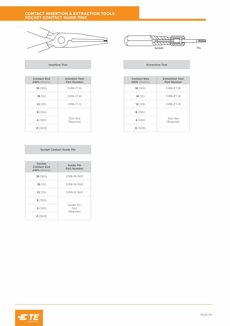
PAGE 90
Contact SizeAWG (Metric)
Insertion Tool Part Number
16 (16S) CIRB-IT-16
16 (15) CIRB-IT-16
12 (25) CIRB-IT-12
8 (100)
Tool NotRequired4 (160)
0 (500)
Socket Contact SizeAWG (Metric)
Guide Pin Part Number
16 (16S) CIRB-16-SGP
16 (15) CIRB-16-SGP
12 (25) CIRB-12-SGP
8 (100)
Guide PinNot
Required4 (160)
0 (500)
Contact SizeAWG (Metric)
Extraction Tool Part Number
16 (16S) CIRB-ET-16
16 (15) CIRB-ET-16
12 (25) CIRB-ET-12
8 (100)
Tool NotRequired4 (160)
0 (500)
CONTACT INSERTION & EXTRACTION TOOLS SOCKET CONTACT GUIDE PINS
Insertion Tool
Socket Contact Guide Pin
Extraction Tool
Socket Pin

RAIL /// CIRH: MODULAR BAYONET LOCK CONNECTOR
Contact Size & Type
ContactPart Number
Wire Size C.S.A. mm2
ToolRequired
Turret/ Locator
ToolSetting
Tool Pos’n If
Applicable
InsertionTool
ExtractionTool
GuidePins
16S/20 Pin CIRB16S/20KPKF80 0,5/0,6 FT8/WA27F TP1249 3 - CIRIT16 CIRET16 -
16S/20 Skt. CIRB16S/20KSKF80 0,5/0,6 FT8/WA27F TP1249 3 - CIRIT16 CIRET16 CIRB16SG
16S/18 Pin CIRB16S/18KPKF80 0,75/0,93 FT8/WA27F TP1249 4 - CIRIT16 CIRET16 -
16S/18 Skt. CIRB16S/18KSKF80 0,75/0,93 FT8/WA27F TP1249 4 - CIRIT16 CIRET16 CIRB16SG
16S/14 Pin CIRB16S/14KPKf80 1,94/2,08 FT8/WA27F TP1249 5 - CIRIT16 CIRET16 -
16S/14 Skt. CIRB16S/14KSKf80 1,94/2,08 FT8/WA27F TP1249 5 - CIRIT16 CIRET16 CIRB16SG
16S/12 Pin CIRB16S/12KPKf80 2,50/3,00 FT8/WA27F TP1249 7 - CIRIT16 CIRET16 -
16S/12 Skt. CIRB16S/12KPKf80 2,50/3,00 FT8/WA27F TP1249 7 - CIRIT16 CIRET16 CIRB16SG
16S Pin CIRB16SKPKF80 0,93/1,5 FT8/WA27F TP1249 5 - CIRIT16 CIRET16 -
16S Skt. CIRB16SKSKF80 0,93/1,5 FT8/WA27F TP1249 5 - CIRIT16 CIRET16 CIRB16SG
LIF 16S Skt. CIRB16SKLKF80 0,93/1,5 FT8/WA27F TP1249 5 - CIRIT16 CIRET16 CIRB16SG
16/22 Pin CIRB16/22KPKF80 0,22/0,34 FT8/WA27F TH592 2/3 Red CIRIT16 CIRET16 -
16/22 Skt. CIRB16/22KSKF80 0,22/0,34 FT8/WA27F TH592 2/3 Blue CIRIT16 CIRET16 CIRB16SG
16/20 Pin CIRB16/20KPKF80 0,5/0,6 FT8/WA27F TH592 3 Blue CIRIT16 CIRET16 -
16/20 Skt. CIRB16/20KSKF80 0,5/0,6 FT8/WA27F TH592 3 Red CIRIT16 CIRET16 CIRB16SG
LIF16/20 Skt. CIRB16/20KLKF80 0,5/0,6 FT8/WA27F TH592 3 Red CIRIT16 CIRET16 CIRB16SG
16/18 Pin CIRB16/18KPKF80 0,75/0,93 FT8/WA27F TH592 4 Blue CIRIT16 CIRET16 -
16/18 Skt. CIRB16/18KSKF80 0,75/0,93 FT8/WA27F TH592 4 Red CIRIT16 CIRET16 CIRB16SG
16 Pin CIRB16KPKF80 0,93/1,5 FT8/WA27F TH592 5 Blue CIRIT16 CIRET16 -
16 Skt. CIRB16KSKF80 0,93/1,5 FT8/WA27F TH592 5 Red CIRIT16 CIRET16 CIRB16SG
LIF 16 Skt. CIRB16KLKF80 0,93/1,5 FT8/WA27F TH592 5 Red CIRIT16 CIRET16 CIRB16SG
16/14 Pin CIRB16/14KPKF80 1,94/2,08 FT8/WA27F TH592 5 Blue CIRIT16 CIRET16 -
16/14 Skt. CIRB16/14KSKF80 1,94/2,08 FT8/WA27F TH592 5 Red CIRIT16 CIRET16 CIRB16SG
16/12 Pin CIRB16/12KPKF80 2,50/3,00 FT8/WA27F TH592 7 Yellow CIRIT16 CIRET16 -
16/12Skt. CIRB16/12KSKF80 2,50/3,00 FT8/WA27F TH592 7 Yellow CIRIT16 CIRET16 CIRB16SG
12/20 Pin CIRB12/20KPKF80 0,5/0,6 FT8/WA27F TH592 3 Yellow CIRIT12 CIRET12 -
12/20 Skt. CIRB12/20KSKF80 0,5/0,6 FT8/WA27F TH592 3 Yellow CIRIT12 CIRET12 CIRB12SG
LIF 12/20 Skt. CIRB12/20KLKF80 0,5/0,6 FT8/WA27F TH592 3 Yellow CIRIT12 CIRET12 CIRB12SG
12/18 Pin CIRB12/18KPKF80 0,75/0,93 FT8/WA27F TH592 4 Yellow CIRIT12 CIRET12 -
12/18 Skt. CIRB12/18KSKF80 0,75/0,93 FT8/WA27F TH592 4 Yellow CIRIT12 CIRET12 CIRB12SG
12/16 Pin CIRB12/16KPKF80 0,93/1,5 FT8/WA27F TH592 5 Yellow CIRIT12 CIRET12 -
12/16 Skt. CIRB12/16KSKF80 0,93/1,5 FT8/WA27F TH592 5 Yellow CIRIT12 CIRET12 CIRB12SG
LIF 12/16 Skt. CIRB12/16KLKF80 0,93/1,5 FT8/WA27F TH592 5 Yellow CIRIT12 CIRET12 CIRB12SG
12/14 Pin CIRB12/14KPKF80 1,94/2,08 FT8/WA27F TH592 5 Yellow CIRIT12 CIRET12 -
12/14 Skt. CIRB12/14KSKF80 1,94/2,08 FT8/WA27F TH592 5 Yellow CIRIT12 CIRET12 CIRB12SG
12 Pin CIRB12KPKF80 2,50/3,00 FT8/WA27F TH592 7 Yellow CIRIT12 CIRET12 -
12 Skt. CIRB12KSKF80 2,50/3,00 FT8/WA27F TH592 7 Yellow CIRIT12 CIRET12 CIRB12SG
LIF 12 Skt. CIRB12KLKF80 2,50/3,00 FT8/WA27F TH592 7 Yellow CIRIT12 CIRET12 CIRB12SG
12/10 Pin CIRB12/10KPKF80 5,53 M310 TH592 5 Yellow CIRIT12 CIRET12 -
12/10 Skt. CIRB12/10KSKF80 5,53 M310 TH592 5 Yellow CIRIT12 CIRET12 CIRB12SG
12/40 Pin CIRB12/40KPKF80 4,0 M310 TH592 5 Yellow CIRIT12 CIRET12 -
12/40 Skt. CIRB12/40KSKF80 4,0 M310 TH592 5 Yellow CIRIT12 CIRET12 CIRB12SG
F80 CONTACTS CRIMP & TOOLING DATA

PAGE 92
Contact Size & Type
ContactPart Number
Wire Size C.S.A. mm2
ToolRequired Turret/ Locator Tool
Setting
Tool Pos’n If
Applicable
InsertionTool
ExtractionTool
GuidePins
8/40 Pin CIRB8/40KPKF80 4,0 D55E Die Set - - - - -
8/40 Skt. CIRB8/40KSKF80 4,0 D55E Die Set - - - - -
8/12 Pin CIRB8/12KPKF80 2,5 M310 Consult TE 3 - - - -
8/12 Skt. CIRB8/12KSKF80 2,5 M310 Consult TE 3 - - - -
8/10 Pin CIRB8/10KPKF80 5,53 D55E Die Set - - - - -
8/10 Skt. CIRB8/10KSKF80 5,53 D55E Die Set - - - - -
8 Pin CIRB8KPKF80 9,0 D36 Die Set 02541 - - - - -
8 Skt. CIRB8KSKF80 9,0 D36 Die Set 02541 - - - - -
100/60 Pin CIRB100/60KPKF80 6,0 D55E Die Set - - - - -
100/60 Skt. CIRB100/60KSKF80 6,0 D55E Die Set - - - - -
100 Pin CIRB100KPKF80 10,0 D55E Die Set MRP0925 - - - - -
100 Skt. CIRB100KSKF80 10,0 D55E Die Set MRP0925 - - - - -
4/10 Pin CIRB4/10KPKF80 5,53 D55E Die Set - - - - -
4/10 Skt. CIRB4/10KSKF80 5,53 D55E Die Set - - - - -
4 Pin CIRB4KPKF80 22,0 D36 Die Set - - - - -
4 Skt. CIRB4KSKF80 22,0 D36 Die Set - - - - -
160 Pin CIRB160KPKF80 16,0 D55E Die Set MRP0924 - - - - -
160 Skt. CIRB160KSKF80 16,0 D55E Die Set MRP0924 - - - - -
0 Pin CIRB0KPKF80 53,0 D36 Die Set - - - - -
0 Skt CIRB0KSKF80 53,0 D36 Die Set - - - - -
500/160 Pin CIRB500/160KPKF8 16,0 D55E Die Set MRP0924 - - - - -
500/160 Skt. CIRB500/160KSKF8 16,0 D55E Die Set MRP0924 - - - - -
500/250 Pin CIRB500/250KPKF8 25,0 D55E Die Set - - - - -
500/250 Skt. CIRB500/250KSKF8 25,0 D55E Die Set - - - - -
500/350 Pin CIRB500/350KPKF8 35,0 D55E Die Set - - - - -
500/350 Skt. CIRB500/350KSKF8 35,0 D55E Die Set - - - - -
500 Pin CIRB500KPKF80 50,0 D55E Die Set MRP0925 - - - - -
500 Skt. CIRB500KSKF80 50,0 D55E Die Set MRP0925 - - - - -
F80 CONTACTS CRIMP & TOOLING DATA CONT.

RAIL /// CIRH: MODULAR BAYONET LOCK CONNECTOR
Contact Size & Type
ContactPart Number
Wire Size C.S.A. mm2
ContactSection
ToolRequired
Turret/ Locator
ToolSetting
Tool Position If Applicable
4 Coax Pin CIRB4CKPKF80P1001 0.5 Inner FT8 TH619 4 Red
Screen D55E/D51 31038 - -
4 Coax Skt CIRB4CKSKF80P1001 0.5 Inner FT8 TH619 4 Blue
Screen D55E/D51 31038 - -
4 Coax Pin CIRB4CKPKF80P1002 1.0 Inner FT8 TH619 4 Red
Screen D55E/D51 HD51-150 - -
4 Coax Skt. CIRB4CKSKF80P1002 1.0 Inner FT8 TH619 4 Blue
Screen D55E/D51 HD51-150 - -
4 Twinax Pin CIRB4TKPKF80P1 0.5/0.6 Inner FT8 TH608 4 Red
Intermediate HX4 Y946 - -
Screen D55E/D51 HD51-150 - -
4 Twinax Skt CIRB4TKSKF80P1 0.5/0.6 Inner FT8 TH608 4 Blue
Intermediate HX4 Y946 - -
Screen D55E/D51 HD51-150 - -
4 Twinax Pin CIRB4TKPKF80P1001 0.75/1.0 Inner FT8 TH608 4 Red
Intermediate HX4 Y946 - -
Screen D55E/D51 HD51-150 - -
4 Twinax Skt. CIRB4TKSKF80P1001 0.75/1.0 Inner FT8 TH608 4 Blue
Intermediate HX4 Y946 - -
Screen D55E/D51 HD51-150 - -
F80 COAX & TWINAX CONTACTS CRIMP & TOOLING DATA
Tool Number Supplier
FT8 DMC
WA27F DMC
TH592 DMC
HT250-3 DMC
67-012-01 DMC
67-016-01 DMC
68-012-01 DMC
68-016-01 DMC
D51 Dubuis
D55E Dubuis

PAGE 94
RFI BRAID SOCK, BANDIT STRAP & KNITMESH BRAID
TE ConnectorsPart Number Diameter Length Max
Shell Size
CIRBMBS035015 ø 20 mm 100 mm 22
CIRBMBS050015 ø 25 mm 150 mm 22
CIRBMBS020010 ø 35 mm 150 mm 32
CIRBMBS025015 ø 50 mm 150 mm 36 & 40
TE ConnectorsPart Number Length Width
CIRBMKM1050 500 mm 25 mm
TE ConnectorsPart Number Length Width Max
Shell Size
CIRB600052 520 mm 6.1 mm 32
CIRB600090 900 mm 6.1 mm 36 & 40
CIRB608109 362 mm 4 mm 22
CIRB600057 07 mm 3 mm 22
TE ConnectorsPart Number Tool Description
CIRB600058 Standard Bandit Tool
CIRB600061 Micro Bandit Tool (3mm Band Straps)
CIRB601200 Calibration Kit
RFI Braid Sock
Knitmesh Braid
Bandit Strap
Bandit Tools

RAIL /// CIRH: MODULAR BAYONET LOCK CONNECTOR
te.com/Rail© 2016 TE Connectivity Ltd. family of companies. All Rights Reserved. 1-1773858-1 JS 0316
EVERY CONNECTION COUNTS, TE Connectivity, TE connectivity (logo) and TE are trademarks of the TE Connectivity group of companies andits licensors.
SNCF, RATP, Alstom, Bombardier, LUL and other product or company names mentioned herein may be trademarks of their respective owners. While TE has made every reasonable effort to ensure the accuracy of the information herein, nothing herein constitutes any guarantee that such information is error-free, or any other representation, warranty or guarantee that the information is accurate, correct, reliable or current. The TE entity issuing this publication reserves the right to make any adjustments to the information contained herein at any time without notice. All implied warranties regarding the information contained herein, including, but not limited to, any implied warranties of merchantability or fitness for a particular purpose are expressly disclaimed.
The dimensions herein are for reference purposes only and are subject to change without notice. Specifications are subject to change without notice. Consult TE for the latest dimensions and design specifications.
For More Information Follow us on Twitter for all the latest product news
@TEConnectivity, and on Facebook, TEConnectivity.
TE Connectivity (TE) Technical Support CenterNorth America +1 800 522 6752
Asia Pacific +86 0 400 820 6015
Austria +43 1 905 601 228
Baltic Regions +46 8 5072 5000
Benelux +31 73 6246 999
Czech Republic +420 800 701 462
France +33 1 34 20 86 86
Germany +49 6251 133 1999
Hungary +36 809 874 04
Italy +39 011 401 2632
Nordic +46 8 5072 5000
Poland +48 800 702 309
Russia +7495 790 790 2
Spain/Portugal +34 93 2910366
Switzerland +41 52 633 66 26
United Kingdom +44 800 267 666