cirrus sr20 (classical cockpit) operating · pdf filecirrus sr20 (classical cockpit) operating...
TRANSCRIPT

Cirrus SR20 (classical cockpit)Operating Manual
This aircraft was designed for MS Flightsimulator™ 2004 only.
The aircraft was developed by:Wolfram Beckert Flight dynamicsGünter Kraemer Model and gaugesThomas Röhl Graphics
Garmin Avionics by Don Kuhn
Please write any comments, suggestions or bug reports to the forum on ourwebsite: http://www.gkflusi.de/nuke
IMPORTANT INFORMATIONThis manual is for use with MS Flightsimulator™ only
NOT FOR REAL WORLD NAVIGATION
1

Table of contentsThe 2D Panel....................................................................................................................... 3Engine Controls [Shift-5]...................................................................................................... 5Radio Stack [Shift-2]............................................................................................................. 6Center Console [Shift-4]....................................................................................................... 7Panel key assignments........................................................................................................ 8The Virtual Cockpit............................................................................................................... 8ARNAV GPS........................................................................................................................ 9Meggitt/S-TEC Altitude Selector/Alerter............................................................................. 10Garmin GMA340 Audio Panel............................................................................................ 12Garmin GNS430 GPS Radios (by Don Kuhn)................................................................... 13Meggitt/S-TEC Fifty Five Autopilot..................................................................................... 16Garmin GTX330 Transponder (by Don Kuhn).................................................................... 17Davtron M803 Digital Clock................................................................................................ 22The CAPS System............................................................................................................. 23The Pilot............................................................................................................................. 23Checklist............................................................................................................................. 24Reference Guide................................................................................................................ 27Credits................................................................................................................................ 29License Information............................................................................................................ 29
2

The 2D Panel
3
1 Annunciator Panel2 Altitude Preselector3 Davtron M803 Digital Clock4 Airspeed Indicator 5 Attitude Indicator6 Altimeter7 Garmin GI102 VOR2 Indicator8 Turn Coordinator9 NSD-360 HSI10 Vertical Speed Indicator11 Switches (left to right)
1 Alternator2 Battery3 Avionics Master Switch4 De-Ice Switch5 Pitot Heat Switch6 Navigation Lights Switch7 Strobe Lights Switch8 Landing Light Switch
12 Interior Light Switches
1 Instrument Lights2 + 3 Cabin Lights
13 ARNAV GPS14 Elevator Trim Down Click Spot15 Autopilot Master Switch Click Spot16 Elevator Trim Up Click Spot17 Rudder Trim18 Elevator Trim Indicator

The panel is equipped with a NSD 360 HSI (9). It can be replaced with Eaglesoft's SANDEL SN3308 payware HSI which is availableon the Eaglesoft website: http://www.eaglesoftdg.com/avionics_catalog.htm
4
19 Starter Switch20 Garmin GNA 340 Audio Panel21 Garmin GNS 430 1 22 Garmin GNS 430 2

Engine Controls [Shift-5]
5
1 Tachometer2 Exhaust Gas / Cylinder Head
Temperature Indicator3 Manifold Pressure / Fuel Flow
Indicator4 Oil Tempreature / Pressure Indicator
5 Volt- / Amperemeter

Radio Stack [Shift-2]
Garmin GNA 340 AudioPanel
Garmin GNS 430 GPS 1
Garmin GNS 430 GPS 2
S-TEC Fifty Five Autopilot
Garmin GTX 330Transponder
Description see below
6

Center Console [Shift-4]
7
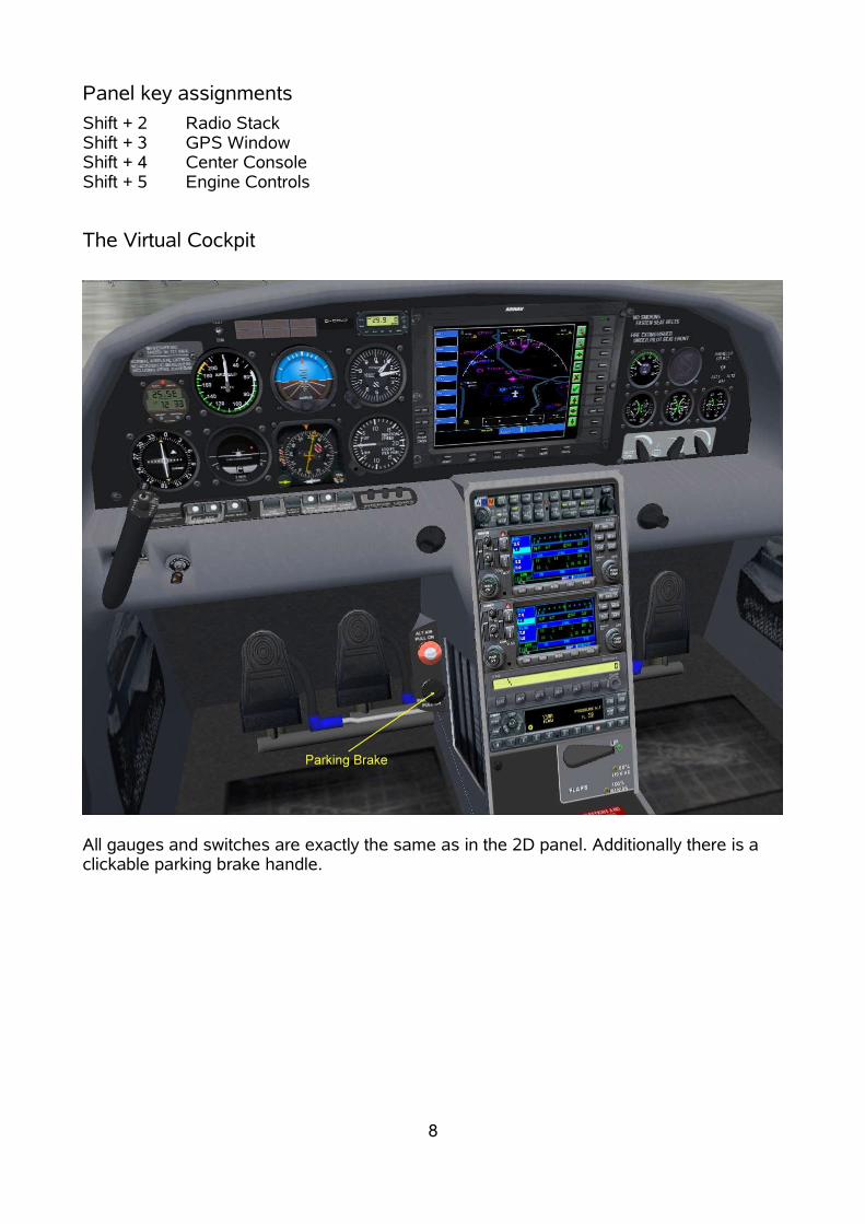
Panel key assignmentsShift + 2 Radio StackShift + 3 GPS WindowShift + 4 Center ConsoleShift + 5 Engine Controls
The Virtual Cockpit
All gauges and switches are exactly the same as in the 2D panel. Additionally there is aclickable parking brake handle.
8
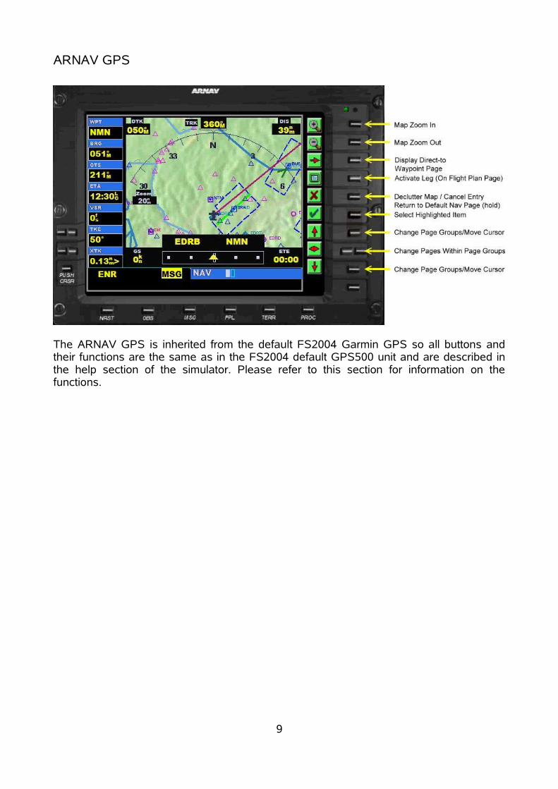
ARNAV GPS
The ARNAV GPS is inherited from the default FS2004 Garmin GPS so all buttons andtheir functions are the same as in the FS2004 default GPS500 unit and are described inthe help section of the simulator. Please refer to this section for information on thefunctions.
9
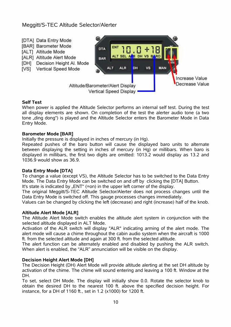
Meggitt/S-TEC Altitude Selector/Alerter
Self TestWhen power is applied the Altitude Selector performs an internal self test. During the testall display elements are shown. On completion of the test the alerter audio tone (a twotone „ding dong“) is played and the Altitude Selector enters the Barometer Mode in DataEntry Mode.
Barometer Mode [BAR]Initially the pressure is displayed in inches of mercury (in Hg).Repeated pushes of the baro button will cause the displayed baro units to alternatebetween displaying the setting in inches of mercury (in Hg) or millibars. When baro isdisplayed in millibars, the first two digits are omitted: 1013.2 would display as 13.2 and1036.9 would show as 36.9.
Data Entry Mode [DTA]To change a value (except VS), the Altitude Selector has to be switched to the Data EntryMode. The Data Entry Mode can be switched on and off by clicking the [DTA] Button. It's state is indicated by „ENT“ (=on) in the upper left corner of the display.The original Meggitt/S-TEC Altitude Selector/Alerter does not process changes until theData Entry Mode is switched off. This gauge processes changes immediately.Values can be changed by clicking the left (decrease) and right (increase) half of the knob.
Altitude Alert Mode [ALR]The Altitude Alert Mode switch enables the altitude alert system in conjunction with theselected altitude displayed in ALT Mode.Activation of the ALR switch will display "ALR" indicating arming of the alert mode. Thealert mode will cause a chime throughout the cabin audio system when the aircraft is 1000ft. from the selected altitude and again at 300 ft. from the selected altitude. The alert function can be alternately enabled and disabled by pushing the ALR switch.When alert is enabled, the “ALR” annunciation will be visible on the display.
Decision Height Alert Mode [DH]The Decision Height (DH) Alert Mode will provide altitude alerting at the set DH altitude byactivation of the chime. The chime will sound entering and leaving a 100 ft. Window at theDH.To set, select DH Mode. The display will initially show 0.0. Rotate the selector knob toobtain the desired DH to the nearest 100 ft. above the specified decision height. Forinstance, for a DH of 1160 ft., set in 1.2 (x1000) for 1200 ft.
10

At the set DH window, the DH alert will activate. In our example, the alert will sound at1250 ft. and again at 1150 ft., alerting the pilot that he is at or near the set decision height.The DH Mode can be disabled by pushing the DH switch causing the DH annunciator toextinguish and returning to the previous display.Repeated activation of the DH button in operate mode will alternately enable or disablethe DH mode.To change the decision height it is necessary to switch off the DH Mode and then switch iton again.
REMARKS:Description partly adopted from the original Meggitt Avionics/S-TEC Pilot's OperatingHandbook.
11
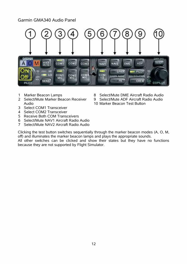
Garmin GMA340 Audio Panel
Clicking the test button switches sequentially through the marker beacon modes (A, O, M,off) and illuminates the marker beacon lamps and plays the appropriate sounds.All other switches can be clicked and show their states but they have no functionsbecause they are not supported by Flight Simulator.
12
1 Marker Beacon Lamps2 Select/Mute Marker Beacon Receiver
Audio3 Select COM1 Transceiver4 Select COM2 Transceiver5 Receive Both COM Transceivers6 Select/Mute NAV1 Aircraft Radio Audio7 Select/Mute NAV2 Aircraft Radio Audio
8 Select/Mute DME Aircraft Radio Audio9 Select/Mute ADF Aircraft Radio Audio10 Marker Beacon Test Button

Garmin GNS430 GPS Radios (by Don Kuhn)
GNS430 Default Map Page
1. The power button turns the unit on and off.
2. The top number in each radio box corresponds to the active frequency, the bottomnumber corresponds to the standby frequency.
3. The active/standby switches toggle the active frequency to standby and the standbyfrequency to active.
4. The radio frequency set switch is used to tune the radios. The click areas are shown inthe figure above.
5. The Com2/Nav2 set toggle switch is used to toggle between tuning the Com and Navradios.
6. The CDI switch ( Nav/GPS switch) toggles between GPS and Nav1 navigation modes.
7. The map page bar switch displays a moving map and various flight information in aboxed rectangle along the right side of the screen. See the accompanying file “430 NavMap Page”.
8. Clicking on the GPS icon will bring up the position page which contains informationboxes displaying information relating to the position of the aircraft and its relativeposition to the next waypoint. A clock displays local or Greenwich mean time. See theaccompanying file “430 Nav Pos Page”.
9. The digital display of GPS waypoint information shows values only for GPS waypoints(excluding TRK and GS). If no waypoint is set in the GPS, the readout will display ----.
13
Com2 Active and Standby Frequencies
Nav2 Active and Standby Frequencies
Power Button
Com2 Active/Standby Frequency Switch
Nav2 Active/Standby Switch
Ident Toggle Switch
Com2/Nav2 Set Switch
Decrease Frequency (MHz)
Decrease Frequency (KHz)
Radio Frequency Set Switch
Increase Frequency (MHz)
Increase Frequency (KHz)
Nav/GPS SwitchDefault/Map Page Switch
Position Page Toggle Switch
CDI Display
To/From Pointer
CDI Needle
Digital Display of GPS Waypoint Information

The values will be displayed whether in the Nav1 or GPS navigation mode.
10.The CDI at the top of the page shows course deviation information in either Nav1 orGPS navigation modes. In the Nav1 mode, the CDI works exactly like the standard CDIdisplay found on most aircraft. The deflection distance of the CDI needle correspondsto ~1 mile on each side of the desired track in the Nav1 mode. It corresponds to a 5mile distance on each side when tracking a waypoint in the GPS mode.
11.All other buttons and their functions are the same as in the FS2004 default GPS500unit and are described in the help section of the simulator. Please refer to this sectionfor information on the functions.
GNS430 Pos Page
1. Flight information boxes contain information relating to the aircraft position in the realworld.
2. Trek graphical readout is self-explanatory. Shows the same information given in theTRK box as a sliding scale representation.
3. The position box lists the latitude and longitude of the aircraft.
4. Local or mean time listed, default is local time.
5. The waypoint boxes contain information relating to the aircraft position relative to thenext GPS waypoint identified.
6. The position page is toggled on or off by clicking on the GPS logo as shown.
14
Position PageToggle Switch
Graphical Readout of Aircraft Trek
Aircraft Latitude and Longitude Position
Local Time (click for GMT)
GPS Waypoint Information Boxes
Flight Information Boxes

7. The position page can be toggled directly from the default Nav or Map pages
8. The default Nav and Map pages cannot be toggled on directly from the position page.You must exit the position page before toggling between these 2 pages (re-click onGPS).
GNS430 NAV Map Page
1. Clicking on the “DEFAULT NAV” logo toggles the Map page on or off.
2. The information bar lists the aircraft ground speed, and the distance and direction(magnetic) of the GPS waypoint identified in the WPT box.
3. The Nav bar is only available on the map pages.
4. The Map page is only available from the default Nav page. It is not available directlyfrom the position page.
15
Digital Display of GPS Waypoint Information
GPS WaypointInformation Bar
Toggle Between Default and Map Pages

Meggitt/S-TEC Fifty Five Autopilot
Self TestWhen power is applied the Autopilot performs an internal self test. During the test alldisplay elements are shown. On completion of the test the RDY symbol is displayed.
OperationAfter self test the autopilot is ready and can be used immediately by pressing one of thebuttons.Clicking the NAV button once sets the autopilot to Nav 1 mode. Clicking a second timesets the GPS mode which is indicated by the GPSS Symbol. Clicking a third time turns offNAV AP.The autopilot can be switched on and off by clicking the Autopilot Master Switch spot ontop of the stick (see 2D Panel).
16

Garmin GTX330 Transponder (by Don Kuhn)
GTX 330 Self-Test Page
1. turns transponder on.
2. turns transponder off.
3. sends a special position identification pulse for 18 seconds for ATC identification (inreal life). Toggles an IDENT display for 18 seconds in FS9. See GTX 330 PrAlt.
4. toggles and sets the transponder code to 1200 directly.
5. toggles between the different display screens.
6. cursor button is used to cancel manual setting of the transponder code at any timein the setting process.
7. clear button is used to reset the flight and count up timers. Also used to go backwhen setting the transponder code.
8. starts and stops the count up timer. Also starts and stops the altitude monitor.
9. lights up when transponder is on.
10.numbers for setting the transponder code manually.
11.brightens transponder background.
12.unbrightens transponder background.
13.display screen.
14.stops the transponder from replying to any interrogations.
15.altitude alert sensor is on when indicated altitude is < or > 5 feet from set altitude.
17
15. Altitude alert sensor
1.On Button2.Off Button
3.Ident Button
4.VFR Button
13.Display screen 5.Function Button
6.Cursor Button
7.Clear Button
8.Start/Stop Button
9.On/Off Indicator10.Transponder Code Set Buttons
12.Turn Bright Off
11.Turn Bright On

Manual Tuning Instructions
Transponder code set number buttons
1. first click on any number button between 0 and 7. This will set that number into the thousand position (first button on the left) and a rectangle will appear behind the second, or hundreds, button. (note: the rectangle is positioned over the number that is to be set.)
2. click again on a number button and that number will be entered into the second, orhundreds, location. The rectangle will move over to the third, or tenths, number.
3. click again on a number button and that number will be entered into the third, ortens, location. The rectangle will move over to the fourth, or ones, number.
4. click again on a number button and that number will be entered into the fourth location. The rectangle will disappear and the new code will be entered into the transponder. (note: the new code will not be entered until the fourth number is clicked.)
5. the number to be set will be shown in the rectangle, and both can be movedbackwards by clicking on the CLR button. Going completely back using the CLRbutton will return the transponder to the previous code.
6. clicking on the CRSR button at any time during the code setting will cancel thesetting and return the transponder to the previous code.
7. note that the VFR frequency 1200 can be set directly by clicking on the VFR button.
18
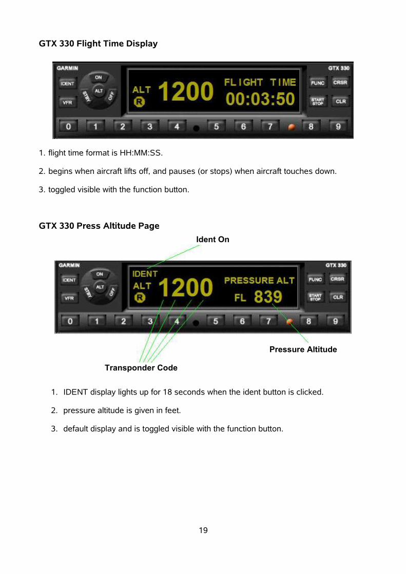
GTX 330 Flight Time Display
1. flight time format is HH:MM:SS.
2. begins when aircraft lifts off, and pauses (or stops) when aircraft touches down.
3. toggled visible with the function button.
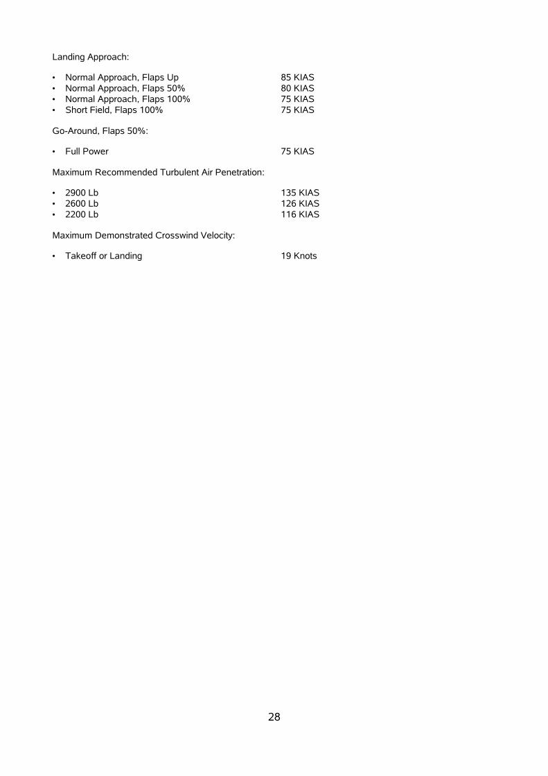
GTX 330 Press Altitude Page
1. IDENT display lights up for 18 seconds when the ident button is clicked.
2. pressure altitude is given in feet.
3. default display and is toggled visible with the function button.
19
Ident On
Transponder Code
Pressure Altitude

GTX 330 Altitude Monitor Display
1. monitors altitude and displays the number of feet above or below the set altitude.
2. displays the word “ABOVE” or “BELOW” depending on the aircraft altitude relativeto that set.
3. toggled visible with the function button.
4. toggled off and on with the start/stop button.
5. sensor light is lit when the indicated altitude is exceeded by +/- 5 feet.
GTX 330 Density Altitude Display
1. displays outside ambient temperature in degrees Celsius.
2. displays density altitude in feet.
3. toggled visible with the function button.
20
Outside ambient temperature
Density altitude

GTX 330 Count Up Timer Display
1. count time format is HH:MM:SS.
2. start/stop and reset (clr) buttons are self-explanatory.
3. toggled visible with the function button.
21
start/stop timerreset timer

Davtron M803 Digital Clock
The upper display can be switched to Voltage, O.A.T Fahrenheit and O.A.T Centigrade.The actual mode is indicated by a letter behind the value.E indicates VoltageF indicates O.A.T FahrenheitC indicates O.A.T CentigradeOn power up the Voltage mode is selected.
The lower display shows time information and can be switched to UT, local time, flighttime and elapsed time.The selected mode is indicated in the left part of the clock display.UT indicates „Universal Time“, also known as GMT (Greenwich Mean Time)LT indicates local timeFT indicates flight timeET indicates elapsed time
The Timer Control Button starts and resets the timer in ET mode.
22

The CAPS SystemThe CAPS (Cirrus Airframe Parachute System) can be activated using the „Spoiler“ key.In the default key assignment table it is the [#] - key.
After deploying the parachute the aircraft will descent slowly and we hope that you willreach the earth's surface without any injuries.
The PilotThe pilot figure can be removed using the „Tailhook“ key. In the default key assignment table it is the [Ctrl-W] - key.
23

ChecklistBefore Starting EngineSeat Belts FASTENEDParking Brakes SETPower Lever FULL BACKMagneto/Starter Switch OFFBat-Alt Master Switches OFFAvionics Master Switch OFFFuel Boost Pump Switch OFFMixture CUTOFF
Starting EngineBrakes HOLDBat-Alt Master Switches ON (Check Volts)Fuel Selector FULLEST TANKFuel Quantity CHECKMixture FULL RICHPower Lever FULL FORWARDBoost Pump PRIME (2-4 seconds), then BOOSTPropeller Area CLEARPower Lever OPEN ¼ INCHIgnition Switch START (Release after engine starts)Power Lever RETARD (to maintain 1000 RPM)Oil Pressure CHECKAvionics Power Switch ONEngine Parameters MONITORAmmeter CHECKTransponder STBY
Before TaxiingBrakes CHECKFlaps UP (0%)Radios/Avionics AS REQUIREDCabin Heat/Defrost AS REQUIRED
TaxiingDirectional Gyro/HSI Orientation CHECK
Before TakeoffBrakes HOLDFlight Controls FREE & CORRECTTrim SET TakeoffFlaps SET 50% & CHECKFlight and Engine Instruments CHECKDirectional Gyro, Altimeter CHECK & SETFuel Quantity CONFIRMFuel Selector FULLEST TANKPropeller CHECK
a. Power Lever INCREASE to detentb. Note RPM rises to approximately 2000 RPM then drops by approximately 100 RPM
as Power Lever is set in detent.c. Power Lever 1700 RPM
Alternator CHECK a. Landing Light ON (3-5 seconds)
24

b. Note ammeter remains within the needle width.Voltage CHECKPower Lever DECREASE to 1000 RPMTransponder ALT Navigation Radios/GPS SET for TakeoffPitot Heat ON, AS REQUIRED
Normal TakeoffPower Lever FULL FORWARDEngine Instruments CHECKBrakes RELEASE (Steer with Rudder Only)Elevator Control Rotate Smoothly at 65-70 KIASAt 80 KIAS, Flaps UP
Short Field TakeoffBrakes HOLDPower Lever FULL FORWARDEngine Instruments CHECKBrakes RELEASE (Steer with Rudder Only)Elevator Control Rotate Smoothly at 65 KIASAirspeed at Obstacle 75 KIASAt 80 KIAS, Flaps UP
ClimbClimb Power SET Mixture FULL RICHEngine Instruments CHECKBoost Pump OFF
CruiseCruise Power SETEngine Instruments MONITORFuel Flow and Balance MONITORMixture LEAN as required
DescentAltimeter SETCabin Heat/Defrost AS REQUIREDFuel System CHECKMixture FULL RICHFlaps AS REQUIREDBrake Pressure CHECK
25

Before LandingMixture FULL RICHFlaps AS REQUIREDLanding Light AS REQUIREDAutopilot DISENGAGE
LandingLanding Speed 80 KIASTouchdown MAIN WHEELS FIRSTLanding Roll LOWER NOSE WHEELBrakes MINIMUM REQUIRED
After LandingFlaps UPPower Lever 1000 RPMTransponder STBYPitot Heat OFF
ShutdownAvionics Switch OFFMixture CUTOFFMagneto/Starter Switch OFFBat-Alt Master Switches OFFParking Brake SETThrottle FULL BACKNav Lights OFFFuel Boost Pump Switch OFFFuel Selector OFFPanel Lights OFF
Securing AircraftParking Brake VERIFY SETThrottle VERIFY IDLEAll Switches VERIFY OFF
26

Reference Guide
Airspeed Limitations
Speed KIAS KCAS RemarksVNE 200 201 Never Exceed Speed is the speed limit that may not be
exceeded at any time.VNO 165 165 Maximum Structural Cruising Speed is the speed that
should not be exceeded except in smooth air, and then onlywith caution.
VO
2900 Lb2600 Lb2200 Lb
135126116
135126116
Operating Maneuvering Speed is the maximum speed atwhich full control travel may be used. Below this speed theairplane stalls before limit loads are reached. Above thisspeed, full control movements can damage the airplane.
VFE
50% Flaps100% Flaps
120100
120101
Maximum Flap Extended Speed is the highest speedpermissible with wing flaps extended.
VPD 135 135 Maximum Demonstrated Parachute Deployment Speedis the maximum speed at which parachute deployment
General LimitationsWeight LimitsMaximum Takeoff Weight 2900 lb (1315 kg)Maximum Weight in Baggage Compartment 130 lb (59 kg)
Maximum Operating AltitudeMaximum Operating Altitude 17,500 ft MSL
Airspeeds for Normal OperationTakeoff Rotation:• Normal, Flaps 50% 70 KIAS• Short Field, Flaps 50% 65 KIAS• Obstacle Clearance, Flaps 50% 75 KIAS
Enroute Climb, Flaps Up:
• Normal, SL 100 KIAS• Normal, 10,000’ 90 KIAS• Best Rate of Climb, SL 94 KIAS• Best Rate of Climb, 10,000’ 89 KIAS• Best Angle of Climb, SL 81 KIAS• Best Angle of Climb, 10,000’ 83 KIAS
27
Landing Approach:
• Normal Approach, Flaps Up 85 KIAS• Normal Approach, Flaps 50% 80 KIAS• Normal Approach, Flaps 100% 75 KIAS• Short Field, Flaps 100% 75 KIAS
Go-Around, Flaps 50%:
• Full Power 75 KIAS
Maximum Recommended Turbulent Air Penetration:
• 2900 Lb 135 KIAS• 2600 Lb 126 KIAS• 2200 Lb 116 KIAS
Maximum Demonstrated Crosswind Velocity:
• Takeoff or Landing 19 Knots
28

CreditsWe want to thank Don Kuhn for the permission to distribute his excellent Garmin Avionicswith our aircraft.
License InformationThis product is freeware and may be freely distributed as long as no payment isrequested.It must not be sold single or as part of a collection without our permission.It may only be uploaded to websites which are available without any cost.It may only be distributed if the original zip file remains unchanged.
Mainz, Germany (EDFZ)May 2005The team:➢ Wolfram Beckert➢ Günter Kraemer➢ Thomas Röhl
29