cisco call manager
TRANSCRIPT
Corporate HeadquartersCisco Systems, Inc.170 West Tasman DriveSan Jose, CA 95134-1706USAhttp://www.cisco.comTel: 408 526-4000
800 553-NETS (6387)Fax: 408 526-4100
Cisco IP Phone Administration Guide for Cisco CallManager 3.3Cisco IP Phones 7902G, 7905G, and 7912G
Text Part Number: OL-6313-01

THE SPECIFICATIONS AND INFORMATION REGARDING THE PRODUCTS IN THIS MANUAL ARE SUBJECT TO CHANGE WITHOUT NOTICE. ALL STATEMENTS, INFORMATION, AND RECOMMENDATIONS IN THIS MANUAL ARE BELIEVED TO BE ACCURATE BUT ARE PRESENTED WITHOUT WARRANTY OF ANY KIND, EXPRESS OR IMPLIED. USERS MUST TAKE FULL RESPONSIBILITY FOR THEIR APPLICATION OF ANY PRODUCTS.
THE SOFTWARE LICENSE AND LIMITED WARRANTY FOR THE ACCOMPANYING PRODUCT ARE SET FORTH IN THE INFORMATION PACKET THAT SHIPPED WITH THE PRODUCT AND ARE INCORPORATED HEREIN BY THIS REFERENCE. IF YOU ARE UNABLE TO LOCATE THE SOFTWARE LICENSE OR LIMITED WARRANTY, CONTACT YOUR CISCO REPRESENTATIVE FOR A COPY.
The following information is for FCC compliance of Class B devices: The equipment described in this manual generates and may radiate radio-frequency energy. If it is not installed in accordance with Cisco’s installation instructions, it may cause interference with radio and television reception. This equipment has been tested and found to comply with the limits for a Class B digital device in accordance with the specifications in part 15 of the FCC rules. These specifications are designed to provide reasonable protection against such interference in a residential installation. However, there is no guarantee that interference will not occur in a particular installation.
Modifying the equipment without Cisco’s written authorization may result in the equipment no longer complying with FCC requirements for Class A or Class B digital devices. In that event, your right to use the equipment may be limited by FCC regulations, and you may be required to correct any interference to radio or television communications at your own expense.
You can determine whether your equipment is causing interference by turning it off. If the interference stops, it was probably caused by the Cisco equipment or one of its peripheral devices. If the equipment causes interference to radio or television reception, try to correct the interference by using one or more of the following measures:
• Turn the television or radio antenna until the interference stops.• Move the equipment to one side or the other of the television or radio.• Move the equipment farther away from the television or radio.• Plug the equipment into an outlet that is on a different circuit from the television or radio. (That is, make certain the equipment and the television or radio are on circuits controlled by different circuit breakers or fuses.)
Modifications to this product not authorized by Cisco Systems, Inc. could void the FCC approval and negate your authority to operate the product.
The Cisco implementation of TCP header compression is an adaptation of a program developed by the University of California, Berkeley (UCB) as part of UCB’s public domain version of the UNIX operating system. All rights reserved. Copyright © 1981, Regents of the University of California.
NOTWITHSTANDING ANY OTHER WARRANTY HEREIN, ALL DOCUMENT FILES AND SOFTWARE OF THESE SUPPLIERS ARE PROVIDED “AS IS” WITH ALL FAULTS. CISCO AND THE ABOVE-NAMED SUPPLIERS DISCLAIM ALL WARRANTIES, EXPRESSED OR IMPLIED, INCLUDING, WITHOUT LIMITATION, THOSE OF MERCHANTABILITY, FITNESS FOR A PARTICULAR PURPOSE AND NONINFRINGEMENT OR ARISING FROM A COURSE OF DEALING, USAGE, OR TRADE PRACTICE.
IN NO EVENT SHALL CISCO OR ITS SUPPLIERS BE LIABLE FOR ANY INDIRECT, SPECIAL, CONSEQUENTIAL, OR INCIDENTAL DAMAGES, INCLUDING, WITHOUT LIMITATION, LOST PROFITS OR LOSS OR DAMAGE TO DATA ARISING OUT OF THE USE OR INABILITY TO USE THIS MANUAL, EVEN IF CISCO OR ITS SUPPLIERS HAVE BEEN ADVISED OF THE POSSIBILITY OF SUCH DAMAGES.
CCSP, the Cisco Square Bridge logo, Cisco Unity, Follow Me Browsing, FormShare, and StackWise are trademarks of Cisco Systems, Inc.; Changing the Way We Work, Live, Play, and Learn, and iQuick Study are service marks of Cisco Systems, Inc.; and Aironet, ASIST, BPX, Catalyst, CCDA, CCDP, CCIE, CCIP, CCNA, CCNP, Cisco, the Cisco Certified Internetwork Expert logo, Cisco IOS, Cisco Press, Cisco Systems, Cisco Systems Capital, the Cisco Systems logo, Empowering the Internet Generation, Enterprise/Solver, EtherChannel, EtherFast, EtherSwitch, Fast Step, GigaDrive, GigaStack, HomeLink, Internet Quotient, IOS, IP/TV, iQ Expertise, the iQ logo, iQ Net Readiness Scorecard, LightStream, Linksys, MeetingPlace, MGX, the Networkers logo, Networking Academy, Network Registrar, Packet, PIX, Post-Routing, Pre-Routing, ProConnect, RateMUX, Registrar, ScriptShare, SlideCast, SMARTnet, StrataView Plus, SwitchProbe, TeleRouter, The Fastest Way to Increase Your Internet Quotient, TransPath, and VCO are registered trademarks of Cisco Systems, Inc. and/or its affiliates in the United States and certain other countries.
All other trademarks mentioned in this document or Website are the property of their respective owners. The use of the word partner does not imply a partnership relationship between Cisco and any other company. (0406R)
Cisco IP Phone Administration Guide for Cisco CallManager 3.3, Cisco IP Phones 7902G, 7905G, and 7912GCopyright © 2000-2004 Cisco Systems, Inc. All rights reserved.
Cisco IP Phone Administration Guide for OL-6313-01
C O N T E N T S
Preface xi
Overview xi
Audience xi
Objectives xii
Organization xii
Related Documentation xiii
Obtaining Documentation xiv
World Wide Web xiv
Documentation CD-ROM xiv
Ordering Documentation xiv
Documentation Feedback xiv
Obtaining Technical Assistance xv
Cisco Connection Online xv
Technical Assistance Center xvi
Obtaining Additional Publications and Information xvii
Document Conventions xviii
C H A P T E R 1 An Overview of the Cisco IP Phone 1-1
Understanding the Cisco IP Phone 7902G 1-2
Understanding the Cisco IP Phone Models 7905G/7912G 1-4
What Networking Protocols Are Used? 1-7
What Features are Supported on the Cisco IP Phone Models 7902G/7905G/7912G? 1-9
Feature Overview 1-9
iiiCisco CallManager 3.3, Cisco IP Phones 7902G/7905G/7912G
Contents
Configuring Telephony Features 1-10
Configuring Network Features Using the Cisco IP Phone 1-11
Providing Users with Feature Information 1-11
Understanding the Requirements for Installing and Configuring the Cisco IP Phone Models 7902G/7905G/7912G 1-12
C H A P T E R 2 Preparing to Install the Cisco IP Phone on Your Network 2-1
Understanding Interactions with Other Cisco IP Telephony Products 2-1
Understanding How the Cisco IP Phone Interacts with Cisco CallManager 2-2
Understanding How the Cisco IP Phone Interacts with the Cisco Catalyst Family of Switches 2-3
Understanding the Phone Startup Process 2-4
Obtaining Power from the Switch 2-4
Loading the Stored Phone Image 2-5
Configuring VLAN 2-5
Obtaining an IP Address 2-5
Accessing TFTP Server 2-6
Requesting Configuration Files 2-6
Contacting Cisco CallManager 2-7
Guidelines for Configuring Ports on the Cisco IP Phone models 7902G/7905G/7912G 2-8
Connecting to the Network 2-8
Using the Network Port 2-8
Using the Access Port 2-9
Providing Power to the Cisco IP Phone 2-9
Power Source Design 2-10
Redundancy Feature 2-11
Connecting a Handset to a Cisco IP Phone 2-11
ivCisco IP Phone Administration Guide for Cisco CallManager 3.3, Cisco IP Phones 7902G/7905G/7912G
OL-6313-01
Contents
Adding Phones to the Cisco CallManager Database 2-12
Using Auto-Registration 2-12
Adding Phones Manually 2-14
Adding Phones Manually Using DHCP 2-14
Assigning Static IP Addresses 2-15
Using the Bulk Administration Tool 2-17
C H A P T E R 3 Installing the Cisco IP Phone 3-1
Before You Begin 3-1
Network Requirements 3-2
Cisco CallManager Configuration 3-2
Safety 3-3
Connecting the Cisco IP Phone to the Network 3-4
Mounting the Phone to the Wall 3-8
Verifying the Phone Startup Process 3-9
Configuring Startup Network Settings 3-10
C H A P T E R 4 Configuring Network Settings on the Cisco IP Phone 4-1
Configuring Methods 4-1
Accessing Network Configuration Settings from a Cisco IP Phone 4-2
Accessing Network Configuration Settings through a Phone’s Web Page 4-3
Verifying Network Settings 4-4
Modifying DHCP Settings 4-9
Enabling DHCP 4-10
Disabling DHCP 4-11
Releasing a DHCP Address 4-13
vCisco IP Phone Administration Guide for Cisco CallManager 3.3, Cisco IP Phones 7902G/7905G/7912G
OL-6313-01
Contents
Configuring IP Settings 4-15
Assigning an IP Address 4-15
Assigning a Default Router 4-17
Assigning a Subnet Mask 4-19
Assigning a Domain Name 4-20
Assigning DNS Servers 4-22
Modifying VLAN Settings 4-24
Configuring VLAN Settings 4-25
Disabling VLAN 4-26
Configuring TFTP Options 4-28
Assigning a TFTP Sever 4-28
Enabling an Alternate TFTP Server 4-30
Assigning a Backup TFTP Server 4-31
Configuring CDP 4-32
C H A P T E R 5 Configuring Users, Features, and Services 5-1
Configuring Telephony Features Using Cisco CallManager Administration 5-2
Configuring Telephony Features for the Cisco IP Phone models 7902G/7905G/7912G 5-2
Adding Users to Cisco CallManager 5-7
Configuring the Corporate Directory 5-7
Setting Up Services 5-8
Providing Information to Users Via a Web Site 5-9
How Users Obtain Support for the Cisco IP Phone 5-9
How Users Get Copies of Cisco IP Phone Manuals 5-9
How Users Subscribe to Services and Configure Phone Features 5-10
How Users Configure Phone Features 5-11
How Users Access Voice Messages 5-11
viCisco IP Phone Administration Guide for Cisco CallManager 3.3, Cisco IP Phones 7902G/7905G/7912G
OL-6313-01
Contents
C H A P T E R 6 Troubleshooting the Cisco IP Phone 6-1
Obtaining Status, Model, and Version Information 6-2
Viewing Status Messages 6-2
Displaying Network Statistics 6-3
Verifying Model and Serial Number 6-5
Verifying Firmware Version 6-6
Monitoring Cisco IP Phones Remotely 6-7
Resetting the Cisco IP Phone 6-8
Erasing the Local Configuration 6-8
Updating the Firmware Version 6-10
Checking the Light Indicators on a Cisco IP Phone 7902G 6-11
Resolving Startup Problems 6-12
Symptom: Cisco IP Phone Does Not Start Up 6-12
Symptom: Cisco IP Phone Not Registering with Cisco CallManager 6-13
Registering the Phone with Cisco CallManager 6-14
Checking Network Connectivity 6-14
Verifying TFTP Server Settings 6-15
Verifying IP Addressing and Routing 6-15
Verifying DNS Settings 6-16
Verifying Cisco CallManager Settings 6-16
Cisco CallManager and TFTP Services Are Not Running 6-16
Creating a New Configuration File 6-17
Symptom: Cisco IP Phone Resetting 6-18
Verifying Physical Connection 6-19
Identifying Intermittent Network Outages 6-19
Verifying DHCP Settings 6-19
Checking Static IP Address Settings 6-19
Verifying Voice VLAN Configuration 6-20
Verifying that the Phones Have Not Been Intentionally Reset 6-20
viiCisco IP Phone Administration Guide for Cisco CallManager 3.3, Cisco IP Phones 7902G/7905G/7912G
OL-6313-01
Contents
Eliminating DNS or Other Connectivity Errors 6-20
Resolving Known Issues 6-21
Where to Go for More Information 6-23
A P P E N D I X A Additional Configuration Methods, Parameters, and Procedures A-1
TFTP Configuring A-2
About Profile Files A-3
Creating or Updating a Profile File A-4
Profile File Conventions A-4
Editing a Profile File and Converting it to Binary Format A-5
Web Page Configuring A-6
Device Information A-8
Network Configuration A-8
Network Statistics A-10
Device Logs A-11
Configuration Parameters A-11
Network Parameters A-11
Tone Parameters A-16
Audio Parameters A-19
Profile File Parameters A-20
Specifying Firmware Upgrade Instructions for the Cisco IP Phone A-21
Using the Interactive Voice Response (IVR) System on the Cisco IP Phone 7902G A-22
IVR System Menu Codes A-22
Entering Data in the IVR System A-24
Navigating the IVR System A-26
Changing the Logo on the Cisco IP Phone LCD Screen A-27
Collecting Information for Troubleshooting A-30
viiiCisco IP Phone Administration Guide for Cisco CallManager 3.3, Cisco IP Phones 7902G/7905G/7912G
OL-6313-01

Contents
A P P E N D I X B Technical Specifications B-1
Physical and Operating Environment Specifications B-1
Cable Specifications B-2
Network Port Pinouts B-2
IN D E X
ixCisco IP Phone Administration Guide for Cisco CallManager 3.3, Cisco IP Phones 7902G/7905G/7912G
OL-6313-01

Contents
xCisco IP Phone Administration Guide for Cisco CallManager 3.3, Cisco IP Phones 7902G/7905G/7912G
OL-6313-01
Preface
OverviewCisco IP Phone Administration Guide for Cisco CallManager 3.3, Cisco IP Phones 7902G, 7905G, and 7912G provides the information you need to understand, install, configure, and manage the Cisco IP Phone models 7902G, 7905G, and 7912G on your network.
AudienceNetwork engineers, system administrators, or telecom engineers should review this guide to learn the steps required to properly set up the Cisco IP Phone on the network.
The tasks described are considered to be administration-level tasks and are not intended for end-users of the phones. Many of the tasks involve configuring network settings and affect the phone’s ability to function in the network.
Because of the close interaction between the Cisco IP Phone and Cisco CallManager, these tasks require familiarity with Cisco CallManager.
xiCisco IP Phone Administration Guide for Cisco CallManager 3.3, Cisco IP Phones 7902G/7905G/7912G
OL-6313-01

PrefaceObjectives
ObjectivesThis guide provides the required steps to get the Cisco IP Phone up and running on a Voice-over-IP (VoIP) network. Because of the complexity of an IP telephony network, this guide does not provide complete and detailed information for procedures that you need to perform on the Cisco CallManager application or other network devices.
OrganizationThis guide is organized as follows:
Chapter Description
Chapter 1, “An Overview of the Cisco IP Phone” Provides a conceptual overview and description of the Cisco IP Phone.
Chapter 2, “Preparing to Install the Cisco IP Phone on Your Network”
Describes how the IP Phone interacts with other key IP telephony components, and provides an overview of the tasks required prior to installation.
Chapter 3, “Installing the Cisco IP Phone” Describes how to properly and safely install and configure the Cisco IP Phone on your network.
Chapter 4, “Configuring Network Settings on the Cisco IP Phone”
Describes how to configure network settings, verify status, and make global changes to the Cisco IP Phone.
Chapter 5, “Configuring Users, Features, and Services”
Provides an overview of procedures for adding users to the network, configuring corporate directories, and setting up web information services.
Chapter 6, “Troubleshooting the Cisco IP Phone” Provides tips for troubleshooting the Cisco IP Phones.
Appendix A, “Additional Configuration Methods, Parameters, and Procedures”
Describes alternative configuration methods for the Cisco IP Phone.
Appendix B, “Technical Specifications” Provides technical specifications of the Cisco IP Phone.
xiiCisco IP Phone Administration Guide for Cisco CallManager 3.3, Cisco IP Phones 7902G/7905G/7912G
OL-6313-01
PrefaceRelated Documentation
Related DocumentationFor more information about Cisco IP Phones, refer to the following publications, which are available at this location:
http://www.cisco.com/en/US/products/hw/phones/index.html
• Find Your Phone Guide on the Web
• Cisco IP Phone 7902G Quick Start Guide
• At a Glance Cisco IP Phone 7905G
• At a Glance Cisco IP Phone 7912G
• Cisco IP Phone 7902G User Guide for Cisco CallManager
• Cisco IP Phone 7905G/7912G User Guide for Cisco CallManager
• Cisco IP Phone 7905G Quick Reference Card for Cisco CallManager
• Regulatory Compliance and Safety Information for the Cisco IP Phone 7900 Series
For more information about Cisco CallManager, refer to the following publications, which are available at this location:
http://www.cisco.com/en/US/products/sw/voicesw/ps556/prod_technical_documentation.html
Cisco CallManager Administration
• Cisco CallManager Administration Guide
• Cisco CallManager System Guide
• Cisco CallManager Serviceability Administration Guide
• Cisco CallManager Serviceability System Guide
• Bulk Administration Tool User Guide
Cisco IP Phones Services and Features
• Cisco CallManager Features and Services Guide
xiiiCisco IP Phone Administration Guide for Cisco CallManager 3.3, Cisco IP Phones 7902G/7905G/7912G
OL-6313-01
PrefaceObtaining Documentation
Obtaining Documentation
World Wide WebYou can access the most current Cisco documentation on the World Wide Web at http://www.cisco.com, http://www-china.cisco.com, or http://www-europe.cisco.com.
Documentation CD-ROMCisco documentation and additional literature are available in a CD-ROM package, which ships with your product. The Documentation CD-ROM is updated monthly. Therefore, it is probably more current than printed documentation. The CD-ROM package is available as a single unit or as an annual subscription.
Ordering DocumentationRegistered CCO users can order the Documentation CD-ROM and other Cisco Product documentation through our online Subscription Services at http://www.cisco.com/cgi-bin/subcat/kaojump.cgi.
Nonregistered CCO users can order documentation through a local account representative by calling Cisco’s corporate headquarters (California, USA) at 408 526-4000 or, in North America, call 800 553-NETS (6387).
Documentation FeedbackIf you are reading Cisco product documentation on the World Wide Web, you can submit technical comments electronically. Click Feedback in the toolbar and select Documentation. After you complete the form, click Submit to send it to Cisco.
You can e-mail your comments to [email protected].
xivCisco IP Phone Administration Guide for Cisco CallManager 3.3, Cisco IP Phones 7902G/7905G/7912G
OL-6313-01
PrefaceObtaining Technical Assistance
To submit your comments by mail, for your convenience many documents contain a response card behind the front cover. Otherwise, you can mail your comments to the following address:
Cisco Systems, Inc.Document Resource Connection170 West Tasman DriveSan Jose, CA 95134-9883
We appreciate and value your comments.
Obtaining Technical AssistanceCisco provides Cisco Connection Online (CCO) as a starting point for all technical assistance. Warranty or maintenance contract customers can use the Technical Assistance Center. All customers can submit technical feedback on Cisco documentation using the web, e-mail, a self-addressed stamped response card included in many printed docs, or by sending mail to Cisco.
Cisco Connection OnlineCisco continues to revolutionize how business is done on the Internet. Cisco Connection Online is the foundation of a suite of interactive, networked services that provides immediate, open access to Cisco information and resources at anytime, from anywhere in the world. This highly integrated Internet application is a powerful, easy-to-use tool for doing business with Cisco.
CCO’s broad range of features and services helps customers and partners to streamline business processes and improve productivity. Through CCO, you will find information about Cisco and our networking solutions, services, and programs. In addition, you can resolve technical issues with online support services, download and test software packages, and order Cisco learning materials and merchandise. Valuable online skill assessment, training, and certification programs are also available.
Customers and partners can self-register on CCO to obtain additional personalized information and services. Registered users may order products, check on the status of an order and view benefits specific to their relationships with Cisco.
xvCisco IP Phone Administration Guide for Cisco CallManager 3.3, Cisco IP Phones 7902G/7905G/7912G
OL-6313-01
PrefaceObtaining Technical Assistance
You can access CCO in the following ways:
• WWW: www.cisco.com
• Telnet: cco.cisco.com
• Modem using standard connection rates and the following terminal settings: VT100 emulation; 8 data bits; no parity; and 1 stop bit.
– From North America, call 408 526-8070
– From Europe, call 33 1 64 46 40 82
You can e-mail questions about using CCO to [email protected].
Technical Assistance CenterThe Cisco Technical Assistance Center (TAC) is available to warranty or maintenance contract customers who need technical assistance with a Cisco product that is under warranty or covered by a maintenance contract.
To display the TAC web site that includes links to technical support information and software upgrades and for requesting TAC support, use www.cisco.com/techsupport.
To contact by e-mail, use one of the following:
In North America, TAC can be reached at 800 553-2447 or 408 526-7209. For other telephone numbers and TAC e-mail addresses worldwide, consult the following web site: http://www.cisco.com/warp/public/687/Directory/DirTAC.shtml.
Language E-mail Address
English [email protected]
Hanzi (Chinese) [email protected]
Kanji (Japanese) [email protected]
Hangul (Korean) [email protected]
Spanish [email protected]
Thai [email protected]
xviCisco IP Phone Administration Guide for Cisco CallManager 3.3, Cisco IP Phones 7902G/7905G/7912G
OL-6313-01
PrefaceObtaining Additional Publications and Information
Obtaining Additional Publications and InformationInformation about Cisco products, technologies, and network solutions is available from various online and printed sources.
• The Cisco Product Catalog describes the networking products offered by Cisco Systems, as well as ordering and customer support services. Access the Cisco Product Catalog at this URL:
http://www.cisco.com/en/US/products/products_catalog_links_launch.html
• Cisco Press publishes a wide range of networking publications. Cisco suggests these titles for new and experienced users: Internetworking Terms and Acronyms Dictionary, Internetworking Technology Handbook, Internetworking Troubleshooting Guide, and the Internetworking Design Guide. For current Cisco Press titles and other information, go to Cisco Press online at this URL:
http://www.ciscopress.com
• Packet magazine is the Cisco quarterly publication that provides the latest networking trends, technology breakthroughs, and Cisco products and solutions to help industry professionals get the most from their networking investment. Included are networking deployment and troubleshooting tips, configuration examples, customer case studies, tutorials and training, certification information, and links to numerous in-depth online resources. You can access Packet magazine at this URL:
http://www.cisco.com/go/packet
• iQ Magazine is the Cisco bimonthly publication that delivers the latest information about Internet business strategies for executives. You can access iQ Magazine at this URL:
http://www.cisco.com/go/iqmagazine
• Internet Protocol Journal is a quarterly journal published by Cisco Systems for engineering professionals involved in designing, developing, and operating public and private internets and intranets. You can access the Internet Protocol Journal at this URL:
http://www.cisco.com/en/US/about/ac123/ac147/about_cisco_the_internet_protocol_journal.html
xviiCisco IP Phone Administration Guide for Cisco CallManager 3.3, Cisco IP Phones 7902G/7905G/7912G
OL-6313-01
PrefaceDocument Conventions
• Training—Cisco offers world-class networking training. Current offerings in network training are listed at this URL:
http://www.cisco.com/en/US/learning/le31/learning_recommended_training_list.html
Document ConventionsThis document uses the following conventions:
Note Means reader take note. Notes contain helpful suggestions or references to material not covered in the publication.
Convention Description
boldface font Commands and keywords are in boldface.
italic font Arguments for which you supply values are in italics.
[ ] Elements in square brackets are optional.
{ x | y | z } Alternative keywords are grouped in braces and separated by vertical bars.
[ x | y | z ] Optional alternative keywords are grouped in brackets and separated by vertical bars.
string A nonquoted set of characters. Do not use quotation marks around the string or the string will include the quotation marks.
screen font Terminal sessions and information the system displays are in screen font.
boldface screen font Information you must enter is in boldface screen font.
italic screen font Arguments for which you supply values are in italic screen font.
^ The symbol ^ represents the key labeled Control—for example, the key combination ^D in a screen display means hold down the Control key while you press the D key.
< > Nonprinting characters, such as passwords are in angle brackets.
xviiiCisco IP Phone Administration Guide for Cisco CallManager 3.3, Cisco IP Phones 7902G/7905G/7912G
OL-6313-01
PrefaceDocument Conventions
Caution Means reader be careful. In this situation, you might do something that could result in equipment damage or loss of data.
Warnings use the following conventions:
Warning IMPORTANT SAFETY INSTRUCTIONS
This warning symbol means danger. You are in a situation that could cause bodily injury. Before you work on any equipment, be aware of the hazards involved with electrical circuitry and be familiar with standard practices for preventing accidents. Use the statement number provided at the end of each warning to locate its translation in the translated safety warnings that accompanied this device. Statement 1071
SAVE THESE INSTRUCTIONS
Waarschuwing BELANGRIJKE VEILIGHEIDSINSTRUCTIES
Dit waarschuwingssymbool betekent gevaar. U verkeert in een situatie die lichamelijk letsel kan veroorzaken. Voordat u aan enige apparatuur gaat werken, dient u zich bewust te zijn van de bij elektrische schakelingen betrokken risico's en dient u op de hoogte te zijn van de standaard praktijken om ongelukken te voorkomen. Gebruik het nummer van de verklaring onderaan de waarschuwing als u een vertaling van de waarschuwing die bij het apparaat wordt geleverd, wilt raadplegen.
BEWAAR DEZE INSTRUCTIES
Varoitus TÄRKEITÄ TURVALLISUUSOHJEITA
Tämä varoitusmerkki merkitsee vaaraa. Tilanne voi aiheuttaa ruumiillisia vammoja. Ennen kuin käsittelet laitteistoa, huomioi sähköpiirien käsittelemiseen liittyvät riskit ja tutustu onnettomuuksien yleisiin ehkäisytapoihin. Turvallisuusvaroitusten käännökset löytyvät laitteen mukana toimitettujen käännettyjen turvallisuusvaroitusten joukosta varoitusten lopussa näkyvien lausuntonumeroiden avulla.
SÄILYTÄ NÄMÄ OHJEET
xixCisco IP Phone Administration Guide for Cisco CallManager 3.3, Cisco IP Phones 7902G/7905G/7912G
OL-6313-01
PrefaceDocument Conventions
Attention IMPORTANTES INFORMATIONS DE SÉCURITÉ
Ce symbole d'avertissement indique un danger. Vous vous trouvez dans une situation pouvant entraîner des blessures ou des dommages corporels. Avant de travailler sur un équipement, soyez conscient des dangers liés aux circuits électriques et familiarisez-vous avec les procédures couramment utilisées pour éviter les accidents. Pour prendre connaissance des traductions des avertissements figurant dans les consignes de sécurité traduites qui accompagnent cet appareil, référez-vous au numéro de l'instruction situé à la fin de chaque avertissement.
CONSERVEZ CES INFORMATIONS
Warnung WICHTIGE SICHERHEITSHINWEISE
Dieses Warnsymbol bedeutet Gefahr. Sie befinden sich in einer Situation, die zu Verletzungen führen kann. Machen Sie sich vor der Arbeit mit Geräten mit den Gefahren elektrischer Schaltungen und den üblichen Verfahren zur Vorbeugung vor Unfällen vertraut. Suchen Sie mit der am Ende jeder Warnung angegebenen Anweisungsnummer nach der jeweiligen Übersetzung in den übersetzten Sicherheitshinweisen, die zusammen mit diesem Gerät ausgeliefert wurden.
BEWAHREN SIE DIESE HINWEISE GUT AUF.
Avvertenza IMPORTANTI ISTRUZIONI SULLA SICUREZZA
Questo simbolo di avvertenza indica un pericolo. La situazione potrebbe causare infortuni alle persone. Prima di intervenire su qualsiasi apparecchiatura, occorre essere al corrente dei pericoli relativi ai circuiti elettrici e conoscere le procedure standard per la prevenzione di incidenti. Utilizzare il numero di istruzione presente alla fine di ciascuna avvertenza per individuare le traduzioni delle avvertenze riportate in questo documento.
CONSERVARE QUESTE ISTRUZIONI
xxCisco IP Phone Administration Guide for Cisco CallManager 3.3, Cisco IP Phones 7902G/7905G/7912G
OL-6313-01
PrefaceDocument Conventions
Advarsel VIKTIGE SIKKERHETSINSTRUKSJONER
Dette advarselssymbolet betyr fare. Du er i en situasjon som kan føre til skade på person. Før du begynner å arbeide med noe av utstyret, må du være oppmerksom på farene forbundet med elektriske kretser, og kjenne til standardprosedyrer for å forhindre ulykker. Bruk nummeret i slutten av hver advarsel for å finne oversettelsen i de oversatte sikkerhetsadvarslene som fulgte med denne enheten.
TA VARE PÅ DISSE INSTRUKSJONENE
Aviso INSTRUÇÕES IMPORTANTES DE SEGURANÇA
Este símbolo de aviso significa perigo. Você está em uma situação que poderá ser causadora de lesões corporais. Antes de iniciar a utilização de qualquer equipamento, tenha conhecimento dos perigos envolvidos no manuseio de circuitos elétricos e familiarize-se com as práticas habituais de prevenção de acidentes. Utilize o número da instrução fornecido ao final de cada aviso para localizar sua tradução nos avisos de segurança traduzidos que acompanham este dispositivo.
GUARDE ESTAS INSTRUÇÕES
¡Advertencia! INSTRUCCIONES IMPORTANTES DE SEGURIDAD
Este símbolo de aviso indica peligro. Existe riesgo para su integridad física. Antes de manipular cualquier equipo, considere los riesgos de la corriente eléctrica y familiarícese con los procedimientos estándar de prevención de accidentes. Al final de cada advertencia encontrará el número que le ayudará a encontrar el texto traducido en el apartado de traducciones que acompaña a este dispositivo.
GUARDE ESTAS INSTRUCCIONES
xxiCisco IP Phone Administration Guide for Cisco CallManager 3.3, Cisco IP Phones 7902G/7905G/7912G
OL-6313-01
PrefaceDocument Conventions
Varning! VIKTIGA SÄKERHETSANVISNINGAR
Denna varningssignal signalerar fara. Du befinner dig i en situation som kan leda till personskada. Innan du utför arbete på någon utrustning måste du vara medveten om farorna med elkretsar och känna till vanliga förfaranden för att förebygga olyckor. Använd det nummer som finns i slutet av varje varning för att hitta dess översättning i de översatta säkerhetsvarningar som medföljer denna anordning.
SPARA DESSA ANVISNINGAR
xxiiCisco IP Phone Administration Guide for Cisco CallManager 3.3, Cisco IP Phones 7902G/7905G/7912G
OL-6313-01
PrefaceDocument Conventions
xxiiiCisco IP Phone Administration Guide for Cisco CallManager 3.3, Cisco IP Phones 7902G/7905G/7912G
OL-6313-01

PrefaceDocument Conventions
xxivCisco IP Phone Administration Guide for Cisco CallManager 3.3, Cisco IP Phones 7902G/7905G/7912G
OL-6313-01
Cisco IP Phone Administration Guide for Cisco CallManager 3OL-6313-01
C H A P T E R 1
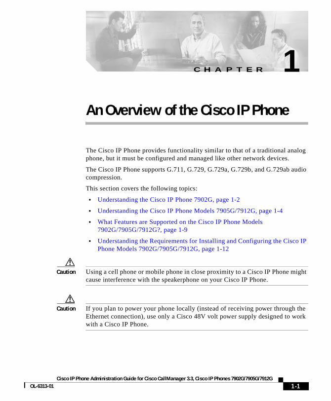
An Overview of the Cisco IP PhoneThe Cisco IP Phone provides functionality similar to that of a traditional analog phone, but it must be configured and managed like other network devices.
The Cisco IP Phone supports G.711, G.729, G.729a, G.729b, and G.729ab audio compression.
This section covers the following topics:
• Understanding the Cisco IP Phone 7902G, page 1-2
• Understanding the Cisco IP Phone Models 7905G/7912G, page 1-4
• What Features are Supported on the Cisco IP Phone Models 7902G/7905G/7912G?, page 1-9
• Understanding the Requirements for Installing and Configuring the Cisco IP Phone Models 7902G/7905G/7912G, page 1-12
Caution Using a cell phone or mobile phone in close proximity to a Cisco IP Phone might cause interference with the speakerphone on your Cisco IP Phone.
Caution If you plan to power your phone locally (instead of receiving power through the Ethernet connection), use only a Cisco 48V volt power supply designed to work with a Cisco IP Phone.
1-1.3, Cisco IP Phones 7902G/7905G/7912G
Chapter 1 An Overview of the Cisco IP PhoneUnderstanding the Cisco IP Phone 7902G
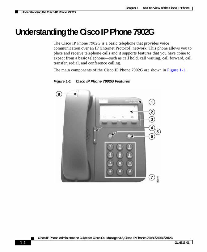
Understanding the Cisco IP Phone 7902GThe Cisco IP Phone 7902G is a basic telephone that provides voice communication over an IP (Internet Protocol) network. This phone allows you to place and receive telephone calls and it supports features that you have come to expect from a basic telephone—such as call hold, call waiting, call forward, call transfer, redial, and conference calling.
The main components of the Cisco IP Phone 7902G are shown in Figure 1-1.
Figure 1-1 Cisco IP Phone 7902G Features
1-2Cisco IP Phone Administration Guide for Cisco CallManager 3.3, Cisco IP Phones 7902G/7905G/7912G
OL-6313-01
Chapter 1 An Overview of the Cisco IP PhoneUnderstanding the Cisco IP Phone 7902G
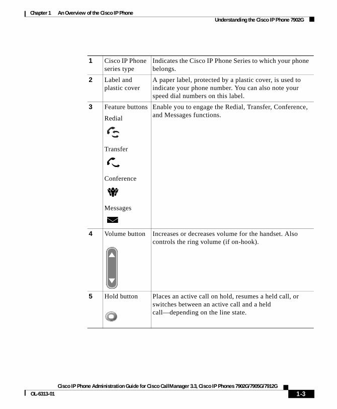
1 Cisco IP Phone series type
Indicates the Cisco IP Phone Series to which your phone belongs.
2 Label and plastic cover
A paper label, protected by a plastic cover, is used to indicate your phone number. You can also note your speed dial numbers on this label.
3 Feature buttons
Redial
Transfer
Conference
Messages
Enable you to engage the Redial, Transfer, Conference, and Messages functions.
4 Volume button Increases or decreases volume for the handset. Also controls the ring volume (if on-hook).
5 Hold button Places an active call on hold, resumes a held call, or switches between an active call and a held call—depending on the line state.
1-3Cisco IP Phone Administration Guide for Cisco CallManager 3.3, Cisco IP Phones 7902G/7905G/7912G
OL-6313-01
Chapter 1 An Overview of the Cisco IP PhoneUnderstanding the Cisco IP Phone Models 7905G/7912G
Understanding the Cisco IP Phone Models 7905G/7912G
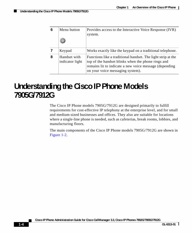
The Cisco IP Phone models 7905G/7912G are designed primarily to fulfill requirements for cost-effective IP telephony at the enterprise level, and for small and medium-sized businesses and offices. They also are suitable for locations where a single-line phone is needed, such as cafeterias, break rooms, lobbies, and manufacturing floors.
The main components of the Cisco IP Phone models 7905G/7912G are shown in Figure 1-2.
6 Menu button Provides access to the Interactive Voice Response (IVR) system.
7 Keypad Works exactly like the keypad on a traditional telephone.
8 Handset with indicator light
Functions like a traditional handset. The light strip at the top of the handset blinks when the phone rings and remains lit to indicate a new voice message (depending on your voice messaging system).
1-4Cisco IP Phone Administration Guide for Cisco CallManager 3.3, Cisco IP Phones 7902G/7905G/7912G
OL-6313-01
Chapter 1 An Overview of the Cisco IP PhoneUnderstanding the Cisco IP Phone Models 7905G/7912G
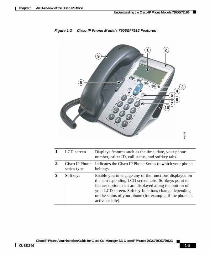
Figure 1-2 Cisco IP Phone Models 7905G/7912 Features
1 LCD screen Displays features such as the time, date, your phone number, caller ID, call status, and softkey tabs.
2 Cisco IP Phone series type
Indicates the Cisco IP Phone Series to which your phone belongs.
3 Softkeys Enable you to engage any of the functions displayed on the corresponding LCD screen tabs. Softkeys point to feature options that are displayed along the bottom of your LCD screen. Softkey functions change depending on the status of your phone (for example, if the phone is active or idle).
9
83
4
65
710
1 2
9103
1
1-5Cisco IP Phone Administration Guide for Cisco CallManager 3.3, Cisco IP Phones 7902G/7905G/7912G
OL-6313-01
Chapter 1 An Overview of the Cisco IP PhoneUnderstanding the Cisco IP Phone Models 7905G/7912G
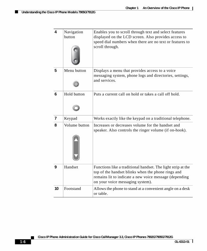
4 Navigation button
Enables you to scroll through text and select features displayed on the LCD screen. Also provides access to speed dial numbers when there are no text or features to scroll through.
5 Menu button Displays a menu that provides access to a voice messaging system, phone logs and directories, settings, and services.
6 Hold button Puts a current call on hold or takes a call off hold.
7 Keypad Works exactly like the keypad on a traditional telephone.
8 Volume button Increases or decreases volume for the handset and speaker. Also controls the ringer volume (if on-hook).
9 Handset Functions like a traditional handset. The light strip at the top of the handset blinks when the phone rings and remains lit to indicate a new voice message (depending on your voice messaging system).
10 Footstand Allows the phone to stand at a convenient angle on a desk or table.
1-6Cisco IP Phone Administration Guide for Cisco CallManager 3.3, Cisco IP Phones 7902G/7905G/7912G
OL-6313-01
Chapter 1 An Overview of the Cisco IP PhoneWhat Networking Protocols Are Used?
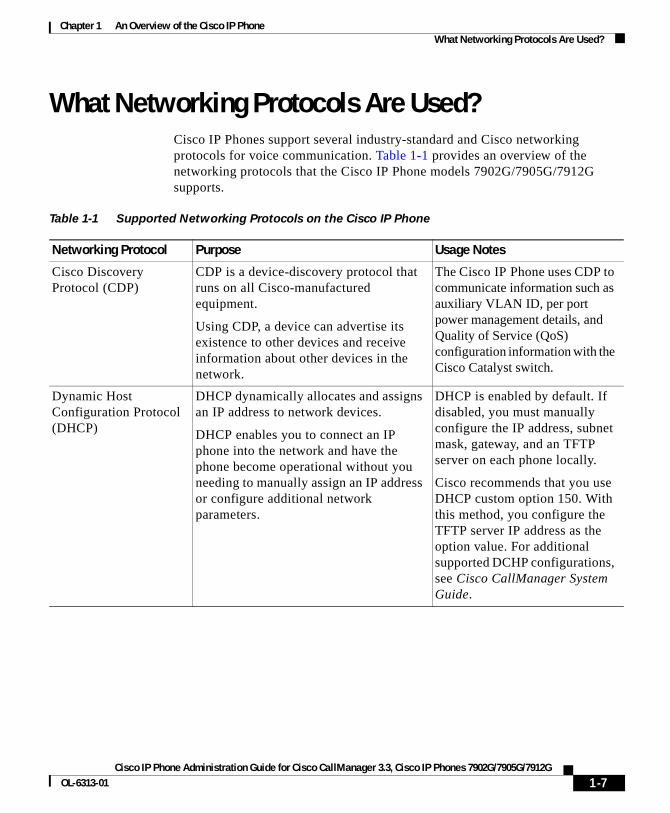
What Networking Protocols Are Used?Cisco IP Phones support several industry-standard and Cisco networking protocols for voice communication. Table 1-1 provides an overview of the networking protocols that the Cisco IP Phone models 7902G/7905G/7912G supports.
Table 1-1 Supported Networking Protocols on the Cisco IP Phone
Networking Protocol Purpose Usage Notes
Cisco Discovery Protocol (CDP)
CDP is a device-discovery protocol that runs on all Cisco-manufactured equipment.
Using CDP, a device can advertise its existence to other devices and receive information about other devices in the network.
The Cisco IP Phone uses CDP to communicate information such as auxiliary VLAN ID, per port power management details, and Quality of Service (QoS) configuration information with the Cisco Catalyst switch.
Dynamic Host Configuration Protocol (DHCP)
DHCP dynamically allocates and assigns an IP address to network devices.
DHCP enables you to connect an IP phone into the network and have the phone become operational without you needing to manually assign an IP address or configure additional network parameters.
DHCP is enabled by default. If disabled, you must manually configure the IP address, subnet mask, gateway, and an TFTP server on each phone locally.
Cisco recommends that you use DHCP custom option 150. With this method, you configure the TFTP server IP address as the option value. For additional supported DCHP configurations, see Cisco CallManager System Guide.
1-7Cisco IP Phone Administration Guide for Cisco CallManager 3.3, Cisco IP Phones 7902G/7905G/7912G
OL-6313-01
Chapter 1 An Overview of the Cisco IP PhoneWhat Networking Protocols Are Used?
Related Topics
• Modifying DHCP Settings, page 4-9
• Configuring IP Settings, page 4-15
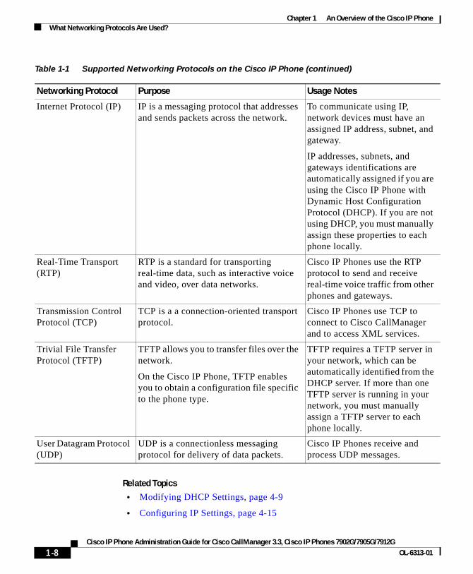
Internet Protocol (IP) IP is a messaging protocol that addresses and sends packets across the network.
To communicate using IP, network devices must have an assigned IP address, subnet, and gateway.
IP addresses, subnets, and gateways identifications are automatically assigned if you are using the Cisco IP Phone with Dynamic Host Configuration Protocol (DHCP). If you are not using DHCP, you must manually assign these properties to each phone locally.
Real-Time Transport (RTP)
RTP is a standard for transporting real-time data, such as interactive voice and video, over data networks.
Cisco IP Phones use the RTP protocol to send and receive real-time voice traffic from other phones and gateways.
Transmission Control Protocol (TCP)
TCP is a a connection-oriented transport protocol.
Cisco IP Phones use TCP to connect to Cisco CallManager and to access XML services.
Trivial File Transfer Protocol (TFTP)
TFTP allows you to transfer files over the network.
On the Cisco IP Phone, TFTP enables you to obtain a configuration file specific to the phone type.
TFTP requires a TFTP server in your network, which can be automatically identified from the DHCP server. If more than one TFTP server is running in your network, you must manually assign a TFTP server to each phone locally.
User Datagram Protocol (UDP)
UDP is a connectionless messaging protocol for delivery of data packets.
Cisco IP Phones receive and process UDP messages.
Table 1-1 Supported Networking Protocols on the Cisco IP Phone (continued)
Networking Protocol Purpose Usage Notes
1-8Cisco IP Phone Administration Guide for Cisco CallManager 3.3, Cisco IP Phones 7902G/7905G/7912G
OL-6313-01
Chapter 1 An Overview of the Cisco IP PhoneWhat Features are Supported on the Cisco IP Phone Models 7902G/7905G/7912G?
• Configuring TFTP Options, page 4-28
• Understanding Interactions with Other Cisco IP Telephony Products, page 2-1
• Understanding the Phone Startup Process, page 2-4
What Features are Supported on the Cisco IP Phone Models 7902G/7905G/7912G?
The Cisco IP Phone models 7902G/7905G/7912G function much like traditional analog phones, allowing you to place and receive telephone calls.
In addition to traditional telephony features, the Cisco IP Phone includes features that enable you to administer and monitor the phone as a network device.
This section includes the following topics:
• Feature Overview, page 1-9
• Configuring Telephony Features, page 1-10
• Configuring Network Features Using the Cisco IP Phone, page 1-11
• Providing Users with Feature Information, page 1-11
Feature OverviewCisco IP Phones provide traditional telephony functionality, such as call forwarding and transferring, redialing, speed dialing, conference calling, and voice messaging system access. Cisco IP phones also provide a variety of other features. For an overview telephony features the Cisco IP Phone models 7902G/7905G/7912G support, and for tips on configuring them, see the “Configuring Telephony Features Using Cisco CallManager Administration” section on page 5-2.
Like other network devices, you must configure the Cisco IP Phones to prepare them to access Cisco CallManager and the rest of the IP network. Using DHCP, you have fewer settings to modify, but you can choose to assign a static IP if your network requires it. For instructions on configuring the network settings on the Cisco IP Phones, see Chapter 4, “Configuring Network Settings on the Cisco IP Phone.”
1-9Cisco IP Phone Administration Guide for Cisco CallManager 3.3, Cisco IP Phones 7902G/7905G/7912G
OL-6313-01
Chapter 1 An Overview of the Cisco IP PhoneWhat Features are Supported on the Cisco IP Phone Models 7902G/7905G/7912G?
The Cisco IP Phone models 7905G/7912G can integrate with the corporate Lightweight Directory Access Protocol 3 (LDAP3) standard directory to enable users to search for co-workers contact information directly from their IP phones. For information about configuring this feature, see the “Configuring the Corporate Directory” section on page 5-7.
Because the Cisco IP Phone is a network device, you can obtain detailed status information from it directly. This information can assist you in troubleshooting any problems users might encounter when using their IP phones. See Chapter 6, “Troubleshooting the Cisco IP Phone” for tips on using this information.
Related Topics
• Configuring Network Settings on the Cisco IP Phone, page 4-1
• Configuring Users, Features, and Services, page 5-1
• Troubleshooting the Cisco IP Phone, page 6-1
Configuring Telephony FeaturesYou can modify additional settings from the Cisco CallManager Administration application. Use this web-based application to set up phone registration criteria and calling search spaces, to configure corporate directories, and to modify phone button templates, among other tasks. See the “Configuring Telephony Features Using Cisco CallManager Administration” section on page 5-2 and the Cisco CallManager Administration Guide for additional information.
If you are not familiar with the Cisco CallManager Administration application, use the context-sensitive help that is available within the application for guidance. You can access context-sensitive help by choosing Help > For this screen from the main menu bar.
This guide provides partial instructions for procedures that involve Cisco CallManager Administration. These instructions are intended to point you to the appropriate window in the Cisco CallManager application and to provide some initial guidance.
For detailed information about using Cisco CallManager, refer to the Cisco CallManager documentation suite that is available at this location:
http://www.cisco.com/univercd/cc/td/doc/product/voice/c_callmg/index.htm
1-10Cisco IP Phone Administration Guide for Cisco CallManager 3.3, Cisco IP Phones 7902G/7905G/7912G
OL-6313-01
Chapter 1 An Overview of the Cisco IP PhoneWhat Features are Supported on the Cisco IP Phone Models 7902G/7905G/7912G?
Related Topic
• Configuring Telephony Features Using Cisco CallManager Administration, page 5-2
Configuring Network Features Using the Cisco IP PhoneYou can locally configure features such as DHCP, TFTP, and IP settings on the phone itself. You can also obtain statistics about a current call or firmware versions on the phone.
For more information about configuring features and viewing statistics from the phone, see Chapter 4, “Configuring Network Settings on the Cisco IP Phone” and Chapter 6, “Troubleshooting the Cisco IP Phone.”
Related Topics
• Configuring Network Settings on the Cisco IP Phone, page 4-1
• Troubleshooting the Cisco IP Phone, page 6-1
Providing Users with Feature InformationIf you are a system administrator, you are likely the primary source of information for Cisco IP Phone users in your network or company. To ensure that you distribute the most current feature and procedural information, familiarize yourself with Cisco IP Phone documentation. Make sure to visit the Cisco IP Phone web site:
http://www.cisco.com/univercd/cc/td/doc/product/voice/c_ipphon/ip_clmgr/english/index.htm.
From this site, you can view and order various user guides, including wallet cards. For complete ordering information, see the “Obtaining Documentation” section on page xiv.
In addition to providing documentation, it is important to inform users of available Cisco IP Phone features—including features specific to your company or network—and of how to access and customize those features, if appropriate.
For a summary of some of the key information that phone users need their system administrators to provide, see the “Providing Information to Users Via a Web Site” section on page 5-9.
1-11Cisco IP Phone Administration Guide for Cisco CallManager 3.3, Cisco IP Phones 7902G/7905G/7912G
OL-6313-01
Chapter 1 An Overview of the Cisco IP PhoneUnderstanding the Requirements for Installing and Configuring the Cisco IP Phone Models 7902G/7905G/7912G
Related Topic
• Providing Information to Users Via a Web Site, page 5-9
Understanding the Requirements for Installing and Configuring the Cisco IP Phone Models 7902G/7905G/7912G
To install and configure the Cisco IP Phone models 7902G/7905G/7912G, you must configure some network settings, set up Cisco CallManager, and make changes locally on the phone.
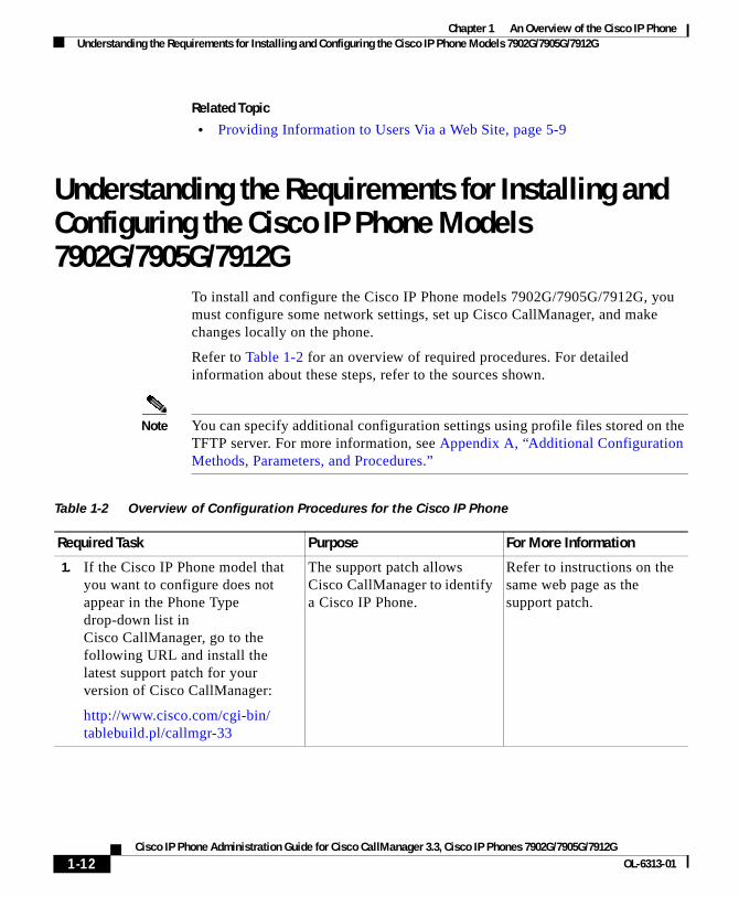
Refer to Table 1-2 for an overview of required procedures. For detailed information about these steps, refer to the sources shown.
Note You can specify additional configuration settings using profile files stored on the TFTP server. For more information, see Appendix A, “Additional Configuration Methods, Parameters, and Procedures.”
Table 1-2 Overview of Configuration Procedures for the Cisco IP Phone
Required Task Purpose For More Information
1. If the Cisco IP Phone model that you want to configure does not appear in the Phone Type drop-down list in Cisco CallManager, go to the following URL and install the latest support patch for your version of Cisco CallManager:
http://www.cisco.com/cgi-bin/tablebuild.pl/callmgr-33
The support patch allows Cisco CallManager to identify a Cisco IP Phone.
Refer to instructions on the same web page as the support patch.
1-12Cisco IP Phone Administration Guide for Cisco CallManager 3.3, Cisco IP Phones 7902G/7905G/7912G
OL-6313-01
Chapter 1 An Overview of the Cisco IP PhoneUnderstanding the Requirements for Installing and Configuring the Cisco IP Phone Models 7902G/7905G/7912G
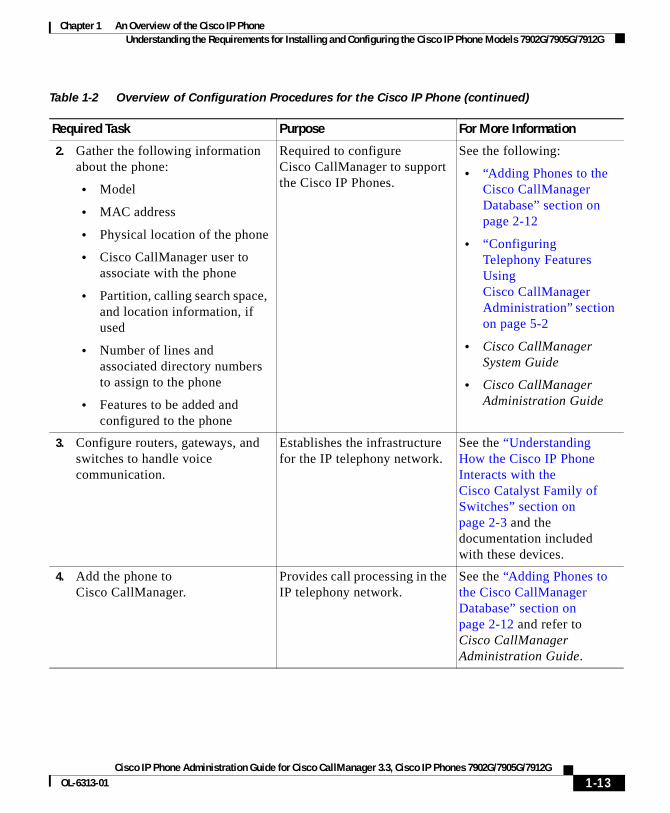
2. Gather the following information about the phone:
• Model
• MAC address
• Physical location of the phone
• Cisco CallManager user to associate with the phone
• Partition, calling search space, and location information, if used
• Number of lines and associated directory numbers to assign to the phone
• Features to be added and configured to the phone
Required to configure Cisco CallManager to support the Cisco IP Phones.
See the following:
• “Adding Phones to the Cisco CallManager Database” section on page 2-12
• “Configuring Telephony Features Using Cisco CallManager Administration” section on page 5-2
• Cisco CallManager System Guide
• Cisco CallManager Administration Guide
3. Configure routers, gateways, and switches to handle voice communication.
Establishes the infrastructure for the IP telephony network.
See the “Understanding How the Cisco IP Phone Interacts with the Cisco Catalyst Family of Switches” section on page 2-3 and the documentation included with these devices.
4. Add the phone to Cisco CallManager.
Provides call processing in the IP telephony network.
See the “Adding Phones to the Cisco CallManager Database” section on page 2-12 and refer to Cisco CallManager Administration Guide.
Table 1-2 Overview of Configuration Procedures for the Cisco IP Phone (continued)
Required Task Purpose For More Information
1-13Cisco IP Phone Administration Guide for Cisco CallManager 3.3, Cisco IP Phones 7902G/7905G/7912G
OL-6313-01

Chapter 1 An Overview of the Cisco IP PhoneUnderstanding the Requirements for Installing and Configuring the Cisco IP Phone Models 7902G/7905G/7912G
5. Choose to auto-register phones, add them to the Cisco CallManager database manually, or use the Bulk Administration Tool (BAT) to add many phones to the database simultaneously.
Determines how the phone is added to Cisco CallManager and how the directory number is assigned.
See the “Adding Phones to the Cisco CallManager Database” section on page 2-12 and refer to Cisco CallManager Administration Guide.
6. Choose to power through the Cisco AC adapter or Cisco Catalyst switch.
Determines whether the phone receives power from an external power source over a power cord or from the in-line power source over the Ethernet cable.
See the “Providing Power to the Cisco IP Phone” section on page 2-9 or the documentation included with the Cisco Catalyst switch.
7. Install the phone in the network. Adds the phone to the network. See Chapter 3, “Installing the Cisco IP Phone”.
8. Configure network settings on the Cisco IP Phone.
Sets IP settings (if not using DHCP in the network) and assigns a TFTP server.
See the “Configuring IP Settings” section on page 4-15 and the “Configuring TFTP Options” section on page 4-28.
9. Configure the phone features such as call waiting, call forward, call park, and call pickup.
Provides enhanced telephony functionality.
See the “Configuring Telephony Features Using Cisco CallManager Administration” section on page 5-2 and refer to Cisco CallManager Administration Guide.
10. Configure directories.
Note This task does not apply to the Cisco IP Phone 7902G.
Integrates with a LDAP3 standard directory, enabling users to search through a corporate directory.
See the “Configuring the Corporate Directory” section on page 5-7 or refer to Cisco CallManager Administration Guide.
Table 1-2 Overview of Configuration Procedures for the Cisco IP Phone (continued)
Required Task Purpose For More Information
1-14Cisco IP Phone Administration Guide for Cisco CallManager 3.3, Cisco IP Phones 7902G/7905G/7912G
OL-6313-01

Chapter 1 An Overview of the Cisco IP PhoneUnderstanding the Requirements for Installing and Configuring the Cisco IP Phone Models 7902G/7905G/7912G
11. Configure Cisco IP Phone services.
Note This task does not apply to the Cisco IP Phone 7902G.
Allows users to quickly access information such as weather quotes, stocks quotes, or other web-based information that uses extensible-markup language (XML).
See the “Setting Up Services” section on page 5-8 and refer to Cisco CallManager Administration Guide.
12. Configure directories.
Note This task does not apply to the Cisco IP Phone 7902G.
Integrates with an LDAP3 standard directory, enabling users to search through a corporate directory.
See the “Configuring the Corporate Directory” section on page 5-7 and refer to Cisco CallManager Administration Guide.
13. Add users to Cisco CallManager. Associates a user with a phone, enabling access to the User Options web-based application where users set up features such as call forwarding and speed dial, and subscribe to services.
See the “Adding Users to Cisco CallManager” section on page 5-7 and refer to Cisco CallManager Administration Guide or the Cisco CallManager application online help.
14. Provide information to end users about how to use their phones and how to configure their phone options.
Ensures that users have adequate information to successfully use their Cisco IP Phones.
See the “Providing Information to Users Via a Web Site” section on page 5-9.
Table 1-2 Overview of Configuration Procedures for the Cisco IP Phone (continued)
Required Task Purpose For More Information
1-15Cisco IP Phone Administration Guide for Cisco CallManager 3.3, Cisco IP Phones 7902G/7905G/7912G
OL-6313-01

Chapter 1 An Overview of the Cisco IP PhoneUnderstanding the Requirements for Installing and Configuring the Cisco IP Phone Models 7902G/7905G/7912G
1-16Cisco IP Phone Administration Guide for Cisco CallManager 3.3, Cisco IP Phones 7902G/7905G/7912G
OL-6313-01
Cisco IP Phone Administration Guide for Cisco CallManager 3OL-6313-01
C H A P T E R 2
Preparing to Install the Cisco IP Phone on Your NetworkCisco IP Phones enable you to communicate using voice over a data network. To provide this capability, the IP Phones depend upon and interact with several other key Cisco IP Telephony components, including Cisco CallManager.
These sections provide you with an important overview of the interaction between the Cisco IP Phone models 7902G/7905G/7912G and other key components of the Voice over IP (VoIP) network:
• Understanding Interactions with Other Cisco IP Telephony Products, page 2-1
• Understanding the Phone Startup Process, page 2-4
• Guidelines for Configuring Ports on the Cisco IP Phone models 7902G/7905G/7912G, page 2-8
• Adding Phones to the Cisco CallManager Database, page 2-12
Understanding Interactions with Other Cisco IP Telephony Products
To function in the IP telephony network, the Cisco IP Phone must be connected to a networking device, such as a Cisco Catalyst switch. You must also register the Cisco IP Phone with a Cisco CallManager system before sending and receiving calls.
2-1.3, Cisco IP Phones 7902G/7905G/7912G
Chapter 2 Preparing to Install the Cisco IP Phone on Your NetworkUnderstanding Interactions with Other Cisco IP Telephony Products
This section covers the following topics:
• Understanding How the Cisco IP Phone Interacts with Cisco CallManager, page 2-2
• Understanding How the Cisco IP Phone Interacts with the Cisco Catalyst Family of Switches, page 2-3
Understanding How the Cisco IP Phone Interacts with Cisco CallManager
Cisco CallManager is an open and industry-standard call processing system. Cisco CallManager software runs on a Windows 2000 server and sets up and tears down calls between phones, integrating traditional PBX functionality with the corporate IP network. Cisco CallManager manages the components of the IP telephony system—the phones, access gateways, and the resources necessary for such features as call conferencing and route planning.
For information about configuring Cisco CallManager to work with the IP devices described in this chapter, refer to Cisco CallManager Administration Guide and Cisco CallManager System Guide.
Note If the Cisco IP Phone model that you want to configure does not appear in the Phone Type drop-down list in Cisco CallManager, go to the following URL and install the latest support patch for your version of Cisco CallManager: http://www.cisco.com/cgi-bin/tablebuild.pl/callmgr-33
Related Topic
• Configuring Telephony Features Using Cisco CallManager Administration, page 5-2
2-2Cisco IP Phone Administration Guide for Cisco CallManager 3.3, Cisco IP Phones 7902G/7905G/7912G
OL-6313-01
Chapter 2 Preparing to Install the Cisco IP Phone on Your NetworkUnderstanding Interactions with Other Cisco IP Telephony Products
Understanding How the Cisco IP Phone Interacts with the Cisco Catalyst Family of Switches
The Cisco IP Phone 7912G has an internal Ethernet switch, enabling it to switch incoming traffic to the phone, the access port, or to the network port (see the “Connecting to the Network” section on page 2-8 for details). The Cisco IP Phone models 7902G/7905G do not include an internal Ethernet switch or an access port.
If a computer is connected to the access port, the computer and the phone share the same physical link to the switch and the same port on the switch.
This shared physical link has the following implications for the VLAN configuration on the network:
• The current VLANs might be configured on an IP subnet basis. However, additional IP addresses may not be available to assign the phone to the same subnet as other devices connected to the same port.
• Data traffic present on the VLAN supporting phones might reduce the quality of Voice-over-IP traffic.
You can resolve these issues by isolating the voice traffic onto a separate VLAN on each of the ports connected to a phone. The switch port configured for connecting a phone would have separate VLANs configured for carrying:
• Voice traffic to and from the IP phone (auxiliary VLAN)
• Data traffic to and from the PC connected to the switch through the access port of the IP phone (native VLAN)
Isolating the phones on a separate, auxiliary VLAN increases the quality of the voice traffic and allows a large number of phones to be added to an existing network where there are not enough IP addresses.
For more information, refer to the documentation included with the Cisco Catalyst switch.
Related Topics
• Connecting to the Network, page 2-8
• Understanding the Phone Startup Process, page 2-4
• Modifying VLAN Settings, page 4-24
2-3Cisco IP Phone Administration Guide for Cisco CallManager 3.3, Cisco IP Phones 7902G/7905G/7912G
OL-6313-01

Chapter 2 Preparing to Install the Cisco IP Phone on Your NetworkUnderstanding the Phone Startup Process
Understanding the Phone Startup ProcessWhen connecting to the VoIP network, the Cisco IP Phone goes through a standard startup process composed of up to seven steps. Depending on your specific network configuration, not all of these steps may occur on your Cisco IP Phone.
Each of these steps is described in the sections that follow:
• Obtaining Power from the Switch, page 2-4
• Loading the Stored Phone Image, page 2-5
• Configuring VLAN, page 2-5
• Obtaining an IP Address, page 2-5
• Accessing TFTP Server, page 2-6
• Requesting Configuration Files, page 2-6
• Contacting Cisco CallManager, page 2-7
Related Topics
• Verifying the Phone Startup Process, page 3-9
• Resolving Startup Problems, page 6-12
Obtaining Power from the SwitchYou can connect the Cisco IP Phone to a Cisco Catalyst switch with one of the modules that provides power to the phone (WS-X6348-RJ45V). See the “Providing Power to the Cisco IP Phone” section on page 2-9 for details.
If you use this optional configuration, the phone receives phantom power and powers up when you connect the Cisco IP Phone to the switch. The phone then sends Cisco Discovery Protocol (CDP) notifications to the switch indicating it is ready to receive CDP packets and indicating the power requirement for the phone. The switch allocates power and sends it over the network cable.
2-4Cisco IP Phone Administration Guide for Cisco CallManager 3.3, Cisco IP Phones 7902G/7905G/7912G
OL-6313-01
Chapter 2 Preparing to Install the Cisco IP Phone on Your NetworkUnderstanding the Phone Startup Process
Related Topics
• Understanding the Phone Startup Process, page 2-4
• Providing Power to the Cisco IP Phone, page 2-9
• Resolving Startup Problems, page 6-12
Loading the Stored Phone ImageThe Cisco IP Phone has non-volatile Flash memory in which it stores firmware images and user-defined preferences. At startup, the phone runs a bootstrap loader that loads a phone image stored in Flash memory. Using this image, the phone initializes its software and hardware.
Related Topics
• Understanding the Phone Startup Process, page 2-4
• Resolving Startup Problems, page 6-12
Configuring VLANIf the Cisco IP Phone is connected to a Cisco Catalyst switch, the switch next informs the phone of the voice VLAN defined on the switch. The phone needs to know its VLAN membership before it can proceed with the Dynamic Host Configuration Protocol (DHCP) request for an IP address.
Related Topics
• Understanding the Phone Startup Process, page 2-4
• Modifying VLAN Settings, page 4-24
• Resolving Startup Problems, page 6-12
Obtaining an IP AddressIf the Cisco IP Phone is using DHCP to obtain an IP address, the phone queries the DHCP server to obtain one. If you are not using DHCP in your network, you must assign static IP addresses to each phone locally.
2-5Cisco IP Phone Administration Guide for Cisco CallManager 3.3, Cisco IP Phones 7902G/7905G/7912G
OL-6313-01
Chapter 2 Preparing to Install the Cisco IP Phone on Your NetworkUnderstanding the Phone Startup Process
Related Topics
• Understanding the Phone Startup Process, page 2-4
• Modifying DHCP Settings, page 4-9
• Configuring IP Settings, page 4-15
• Resolving Startup Problems, page 6-12
Accessing TFTP ServerIn addition to assigning an IP address, the DHCP server directs the Cisco IP Phone to a TFTP Server. If the phone has a statically defined IP address, you must configure the TFTP server locally on the phone; the phone then contacts the TFTP server directly.
Related Topics
• Understanding the Phone Startup Process, page 2-4
• Configuring TFTP Options, page 4-28
• Resolving Startup Problems, page 6-12
Requesting Configuration FilesThe TFTP server has configuration files (.cnf file format or .cnf.xml) for telephony devices, which define parameters for connecting to Cisco CallManager. In general, any time you make a change in Cisco CallManager that requires the phone (device) to be reset, a change has been made to the phone's configuration file.
The .cnf.xml file also contains the information that tells the phone which image load it should be running. If this image load differs from the one currently loaded on the phone, the phone contacts the TFTP server to request the new image file.
The phone first requests the file SEPxxxxxxxxxxxx.cnf.xml, where each xx is the two-digit lowercase hexadecimal representation of each integer in the phone’s MAC address. If the phone cannot find this file, it requests the files XMLDefault.cnf.xml and SEDDefault.cnf.
2-6Cisco IP Phone Administration Guide for Cisco CallManager 3.3, Cisco IP Phones 7902G/7905G/7912G
OL-6313-01
Chapter 2 Preparing to Install the Cisco IP Phone on Your NetworkUnderstanding the Phone Startup Process
After the phone obtains one of the .cnf.xml files or the .cnf file, the Cisco IP Phone 7902G requests the profile file ffxxxxxxxxxxxx, the Cisco IP Phone 7905G requests the profile file ldxxxxxxxxxxxx, and the Cisco IP Phone 7912G requests the profile file gkxxxxxxxxxxxx, where each xx is the two-digit lowercase hexadecimal representation of each integer in the phone’s MAC address. If a phone cannot find this profile file, it requests the profile file ffdefault.cfg for the Cisco IP Phone 7902G, the profile file lddefault.cfg for the Cisco IP Phone 7905G, or the profile file gkdefault.cfg for the Cisco IP Phone 7912G. For more information about profile files, see Appendix A, “Additional Configuration Methods, Parameters, and Procedures.”
After the phone finds one of the profile files, or if it cannot find a profile file, it continues with its startup process.
Related Topics
• Understanding the Phone Startup Process, page 2-4
• Resolving Startup Problems, page 6-12
Contacting Cisco CallManagerThe configuration file defines how the Cisco IP Phone communicates with Cisco CallManager. After obtaining the file from the TFTP server, the phone attempts to make a TCP connection to the highest priority Cisco CallManager on the list.
If the phone was manually added to the database, Cisco CallManager identifies the phone. If the phone was not manually added to the database and auto-registration is enabled in Cisco CallManager, the phone attempts to auto-register itself in the Cisco CallManager database.
Cisco CallManager informs devices using .cnf format configuration files of their load ID. Devices using .xml format configuration files receive the load ID in the configuration file.
Related Topics
• Understanding the Phone Startup Process, page 2-4
• Resolving Startup Problems, page 6-12
2-7Cisco IP Phone Administration Guide for Cisco CallManager 3.3, Cisco IP Phones 7902G/7905G/7912G
OL-6313-01
Chapter 2 Preparing to Install the Cisco IP Phone on Your NetworkGuidelines for Configuring Ports on the Cisco IP Phone models 7902G/7905G/7912G
Guidelines for Configuring Ports on the Cisco IP Phone models 7902G/7905G/7912G
Cisco IP Phones include ports for connecting the phones to the network and for providing power to the phones. These sections provide tips for configuring these ports:
• Connecting to the Network, page 2-8
• Providing Power to the Cisco IP Phone, page 2-9
Connecting to the NetworkThe Cisco IP Phone 7912G has two RJ-45 ports labelled “network” and “access.” The Cisco IP Phone models 7902G/7905G have one RJ-45 port. Each port supports 10/100 Mbps half- or full-duplex connections to external devices. You can use either Category 3 or 5 cabling for 10-Mbps connections, but you must use Category 5 for 100 Mbps connections. On both the network port and access port, use full-duplex mode to avoid collisions.
See Figure 3-1 for the connection ports available on the back of the Cisco IP Phone models 7902G/7905G. See Figure 3-2 for the connection ports available on the back of the Cisco IP Phone 7912G
Related Topics
• Connecting the Cisco IP Phone to the Network, page 3-4
• Using the Network Port, page 2-8
• Using the Access Port, page 2-9
Using the Network Port
Use the network port to connect the phone to the network. You must use a straight-through cable on this port. The phone can also obtain inline power from the Cisco Catalyst switch over this connection. See the “Providing Power to the Cisco IP Phone” section on page 2-9 for details.
2-8Cisco IP Phone Administration Guide for Cisco CallManager 3.3, Cisco IP Phones 7902G/7905G/7912G
OL-6313-01
Chapter 2 Preparing to Install the Cisco IP Phone on Your NetworkGuidelines for Configuring Ports on the Cisco IP Phone models 7902G/7905G/7912G
Related Topics
• Connecting the Cisco IP Phone to the Network, page 3-4
• Providing Power to the Cisco IP Phone, page 2-9
Using the Access Port
Use the access port to connect a network device, such as a computer, to the phone. You must use a straight-through cable on this port.
Related Topic
• Connecting the Cisco IP Phone to the Network, page 3-4
Providing Power to the Cisco IP PhoneYou can power a Cisco IP Phone from an external power supply, from a switch port, or from a power source between the phone and the switch.
The Cisco IP Phone can be powered by the following sources:
• External power—optional Cisco AC adapter and power cord for connecting to a standard wall receptacle.
• Inline power—inline power provider to the Cisco IP Phone when connected to a Cisco Catalyst switch capable of providing inline power.
Note Only the network port supports inline power from the Cisco Catalyst switches.
• WS-PWR-PANEL—power patch panel that allows the Cisco IP Phone to be connected to existing Catalyst 4000, 5000, and 6000 family 10/100BaseTX switching modules.
This module sends power on pins 4, 5, 7, & 8, which are not used for Ethernet signaling. The power patch panel also attempts to verify that the attached device is a Cisco IP Phone before providing power.
2-9Cisco IP Phone Administration Guide for Cisco CallManager 3.3, Cisco IP Phones 7902G/7905G/7912G
OL-6313-01
Chapter 2 Preparing to Install the Cisco IP Phone on Your NetworkGuidelines for Configuring Ports on the Cisco IP Phone models 7902G/7905G/7912G
Related Topics
• Connecting the Cisco IP Phone to the Network, page 3-4
• Connecting to the Network, page 2-8
• Understanding Interactions with Other Cisco IP Telephony Products, page 2-1
• Power Source Design, page 2-10
• Redundancy Feature, page 2-11
Power Source Design
The phone and switch automatically determine which power source the phone uses. If the power has to be switched to a different source, the phone user will experience different results based on which power source is being used by the phone.
Use the following information to choose a power source for the phone:
• If you plug a phone into the optional power supply before plugging it into the network, the phone is powered by the power supply.
• If you then unplug the phone from the power supply, the phone resets. If the switch port is configured for 10/100 Mbps, the switch recognizes the loss of power and brings the phone back up.
• If the switch port is configured for 10 Mbps only, then you must unplug the network connection and plug it back into the phone for the switch to recognize the phone’s loss of power.
• If, however, you plugged the network connection into the phone before you plugged in the power cord, the phone receives power through the switch, and unplugging the power cord will not bring down the phone. If the switch reboots, the phone will then be powered by the power cord.
Related Topics
• Connecting the Cisco IP Phone to the Network, page 3-4
• Connecting to the Network, page 2-8
• Understanding Interactions with Other Cisco IP Telephony Products, page 2-1
• Providing Power to the Cisco IP Phone, page 2-9
2-10Cisco IP Phone Administration Guide for Cisco CallManager 3.3, Cisco IP Phones 7902G/7905G/7912G
OL-6313-01
Chapter 2 Preparing to Install the Cisco IP Phone on Your NetworkGuidelines for Configuring Ports on the Cisco IP Phone models 7902G/7905G/7912G
Redundancy Feature
For redundancy, you can use the Cisco AC adapter even if you are using inline power from the Cisco Catalyst switches. The Cisco IP Phone can share the power load being used from the inline power and external power source. If either the inline power or the external power goes down, the phone can switch entirely to the other power source.
To use this redundancy feature:
1. Set the inline power mode to auto on the Cisco Catalyst switch.
2. Connect the unpowered Cisco IP Phone to the network.
3. Connect the external power supply to the phone after the phone powers up.
Related Topics
• Connecting the Cisco IP Phone to the Network, page 3-4
• Connecting to the Network, page 2-8
• Understanding Interactions with Other Cisco IP Telephony Products, page 2-1
• Providing Power to the Cisco IP Phone, page 2-9
Connecting a Handset to a Cisco IP PhoneEach Cisco IP Phone includes a handset designed especially for use with the phone. These handsets are interchangeable among Cisco IP Phone models. The handsets include a light strip used to indicate voice messages waiting.
To place and answer calls using a handset, plug the included handset into the back of the phone base (see the “Connecting the Cisco IP Phone to the Network” section on page 3-4 for details) and pick up the handset.
2-11Cisco IP Phone Administration Guide for Cisco CallManager 3.3, Cisco IP Phones 7902G/7905G/7912G
OL-6313-01
Chapter 2 Preparing to Install the Cisco IP Phone on Your NetworkAdding Phones to the Cisco CallManager Database
Adding Phones to the Cisco CallManager DatabaseBefore installing any Cisco IP phones, you must make decisions about how you want the phones to be added to the Cisco CallManager database. Because Cisco CallManager handles call processing in the network, this is a critical step.
You can add phones to the Cisco CallManager database automatically using auto-registration, manually using the Cisco CallManager Administration application, or in groups with the Bulk Administration Tool (BAT).
Once you add a Cisco IP phone using the Cisco CallManager Administration application, the Phone Configuration Window in the application displays the device name, registration status, and the IP address of the Cisco CallManager to which the device is registered.
This section covers the following topics:
• Using Auto-Registration, page 2-12
• Adding Phones Manually, page 2-14
• Using the Bulk Administration Tool, page 2-17
Tip To get help using the Cisco CallManager application, access context-sensitive help by choosing Help > For this page from the main menu bar. For complete instructions and conceptual information, refer to Cisco CallManager Administration Guide and Cisco CallManager System Guide.
Using Auto-RegistrationUse auto-registration if you want Cisco CallManager to assign directory numbers automatically to new phones as they connect to the IP telephony network. Once a phone has auto-registered, you can move it to a new location and assign it to a different device pool without affecting its directory number.
With auto-registration enabled, Cisco CallManager begins the automatic startup process to obtain a directory number as soon as you connect the Cisco IP Phone to the network. During auto-registration, Cisco CallManager automatically assigns the next available sequential directory number to the phone.
2-12Cisco IP Phone Administration Guide for Cisco CallManager 3.3, Cisco IP Phones 7902G/7905G/7912G
OL-6313-01
Chapter 2 Preparing to Install the Cisco IP Phone on Your NetworkAdding Phones to the Cisco CallManager Database
Use auto-registration to quickly get all phones into the Cisco CallManager database. You can then modify any settings, such as the directory numbers, from Cisco CallManager. If you do not use auto-registration, you must manually add phones to the Cisco CallManager database or use the Bulk Administration Tool (BAT).
Use the following procedure as a starting point to enable auto-registration using the Cisco CallManager Administration application. For additional information, access context-sensitive help from the application or refer to Cisco CallManager documentation.
Procedure
Step 1 Log in to the Cisco CallManager Administration application.
Step 2 From the menu bar, choose System > Cisco CallManager.
The Cisco CallManager Configuration window appears.
Step 3 Verify that the “Auto-registration disabled on this Cisco CallManager” setting is not checked. Cisco CallManager disables the auto-registration by default to prevent unauthorized connections to the network.
Step 4 To modify phone settings, choose Device > Phone. Use the Find and List Phones window to enter search criteria for each phone.
Step 5 Install the phone by following the instructions in Chapter 3, “Installing the Cisco IP Phone.”
Step 6 To configure additional phone features, see the “Configuring Telephony Features Using Cisco CallManager Administration” section on page 5-2 for details.
Related Topics
• Adding Phones Manually, page 2-14
• Using the Bulk Administration Tool, page 2-17
• Configuring Telephony Features Using Cisco CallManager Administration, page 5-2
2-13Cisco IP Phone Administration Guide for Cisco CallManager 3.3, Cisco IP Phones 7902G/7905G/7912G
OL-6313-01
Chapter 2 Preparing to Install the Cisco IP Phone on Your NetworkAdding Phones to the Cisco CallManager Database
Adding Phones ManuallyIf you want to assign specific directory numbers to a specific Cisco IP Phone without using auto-registration, you can manually add each phone to the Cisco CallManager database or use the Bulk Administration Tool (BAT).
If you want to add phones manually, and are not using Dynamic Host Configuration Protocol (DHCP) in your network, then you must configure the IP settings and Trivial File Transfer Protocol (TFTP) server locally on each phone.
Alternatively, if you use DHCP, but want to manually set the TFTP server, then allow the phone to start up, using DHCP, before re-assigning the TFTP server.
See these topics for more information:
• Adding Phones Manually Using DHCP, page 2-14
• Assigning Static IP Addresses, page 2-15
Adding Phones Manually Using DHCP
If you are using DHCP in your network, but you are not using auto-registration, you can manually add a phone to the Cisco CallManager database. If you are using DHCP, you do not need to assign IP addresses or TFTP servers.
Use the following procedure as a starting point to add phones manually using the Cisco CallManager Administration application.
Procedure
Step 1 Log in to the Cisco CallManager Administration application.
Step 2 From the menu bar, choose Device > Add a New Device.
The Add a New Device window appears.
Step 3 Select Phone from the Device Type drop-down menu and click Next.
The Add a New Phone window appears.
Step 4 Select a phone type from the drop-down menu and click Next.
The Phone Configuration window appears. The fields displayed in this window depend upon the phone type selected.
2-14Cisco IP Phone Administration Guide for Cisco CallManager 3.3, Cisco IP Phones 7902G/7905G/7912G
OL-6313-01
Chapter 2 Preparing to Install the Cisco IP Phone on Your NetworkAdding Phones to the Cisco CallManager Database
Step 5 In the Phone Configuration window, you must enter information in the following fields:
• MAC Address
• Device Pool
Step 6 Click Insert.
The Cisco CallManager Administration application asks if you want to assign a directory number.
Step 7 To configure additional phone features, see the “Configuring Telephony Features Using Cisco CallManager Administration” section on page 5-2 for details.
For additional information, access context-sensitive help from the application or refer to Cisco CallManager documentation.
Related Topics
• Using Auto-Registration, page 2-12
• Assigning Static IP Addresses, page 2-15
• Using the Bulk Administration Tool, page 2-17
• Configuring Telephony Features Using Cisco CallManager Administration, page 5-2
Assigning Static IP Addresses
If you do not use DHCP in your network, you must assign static IP addresses to each phone. You must configure each phone locally.
Use the following procedure as a starting point to add phones manually using the Cisco CallManager Administration application.
Procedure
Step 1 Log in to the Cisco CallManager Administration application.
Step 2 From the menu bar, choose Device > Add a New Device.
The Add a New Device window appears.
2-15Cisco IP Phone Administration Guide for Cisco CallManager 3.3, Cisco IP Phones 7902G/7905G/7912G
OL-6313-01
Chapter 2 Preparing to Install the Cisco IP Phone on Your NetworkAdding Phones to the Cisco CallManager Database
Step 3 Select Phone from the Device Type drop-down menu and click Next.
The Add a New Phone window appears.
Step 4 Select a phone type from the drop-down menu and click Next.
The Phone Configuration window appears. The fields displayed in this window depend upon the phone type selected.
Step 5 In the Phone Configuration window, enter information in the following fields:
• MAC Address
• Device Pool
Step 6 Click Insert.
The Cisco CallManager Administration application asks if you want to assign a directory number.
Step 7 Enter information in the required fields.
Step 8 Install the phone by following the instructions in the Chapter 3, “Installing the Cisco IP Phone.”
Step 9 Configure the IP settings by following the instructions in the “Configuring IP Settings” section on page 4-15.
Step 10 Configure the TFTP server by following the instructions in the “Configuring TFTP Options” section on page 4-28.
Step 11 To configure additional phone features, see the “Configuring Telephony Features Using Cisco CallManager Administration” section on page 5-2 for details.
Related Topics
• Using Auto-Registration, page 2-12
• Adding Phones Manually Using DHCP, page 2-14
• Using the Bulk Administration Tool, page 2-17
• Configuring Telephony Features Using Cisco CallManager Administration, page 5-2
2-16Cisco IP Phone Administration Guide for Cisco CallManager 3.3, Cisco IP Phones 7902G/7905G/7912G
OL-6313-01
Chapter 2 Preparing to Install the Cisco IP Phone on Your NetworkAdding Phones to the Cisco CallManager Database
Using the Bulk Administration ToolThe Cisco Bulk Administration Tool (BAT) is a plug-in application for Cisco CallManager that enables system administrators to perform batch operations, including registration, on large numbers of Cisco IP Phones.
Refer to Bulk Administration Tool Guide for Cisco CallManager for information about using BAT in your network.
Related Topics
• Using Auto-Registration, page 2-12
• Adding Phones Manually, page 2-14
• Configuring Telephony Features Using Cisco CallManager Administration, page 5-2
2-17Cisco IP Phone Administration Guide for Cisco CallManager 3.3, Cisco IP Phones 7902G/7905G/7912G
OL-6313-01

Chapter 2 Preparing to Install the Cisco IP Phone on Your NetworkAdding Phones to the Cisco CallManager Database
2-18Cisco IP Phone Administration Guide for Cisco CallManager 3.3, Cisco IP Phones 7902G/7905G/7912G
OL-6313-01
Cisco IP Phone Administration Guide for Cisco CallManager 3OL-6313-01
C H A P T E R 3
Installing the Cisco IP PhoneThese topics help you install the Cisco IP Phone on an IP telephony network:
• Before You Begin, page 3-1
• Connecting the Cisco IP Phone to the Network, page 3-4
• Mounting the Phone to the Wall, page 3-8
• Verifying the Phone Startup Process, page 3-9
• Configuring Startup Network Settings, page 3-10
Note For each Cisco IP phone that you install in your network, you must first make some critical decisions about how to configure the phone in your network. You can then safely install the phone and verify its functionality. For information on preparing to install, see Chapter 2, “Preparing to Install the Cisco IP Phone on Your Network.”
Before You BeginBefore installing the Cisco IP Phone, review the requirements in these sections:
• Network Requirements, page 3-2
• Cisco CallManager Configuration, page 3-2
• Safety, page 3-3
3-1.3, Cisco IP Phones 7902G/7905G/7912G

Chapter 3 Installing the Cisco IP PhoneBefore You Begin
Network RequirementsFor the Cisco IP Phone to successfully operate as a Cisco IP Phone endpoint in your network, your network must meet the following requirements:
• Working VoIP Network
– Voice over IP (VoIP) configured on your Cisco routers and gateways
– Cisco CallManager Release 3.3 or higher installed in your network and configured to handle call processing
• IP network that supports DHCP or manual assignment of IP address, gateway, and subnet mask
Cisco CallManager ConfigurationThe Cisco IP Phone requires Cisco CallManager to handle call processing. Refer to the Cisco CallManager Administration Guide or context-sensitive help in the Cisco CallManager application to ensure that Cisco CallManager is set up properly to manage the phone and to properly route and process calls.
If you plan to use auto-registration, verify that it is enabled and properly configured in Cisco CallManager before connecting any Cisco IP Phone to the network. See the “Using Auto-Registration” section on page 2-12 for details.
You must use Cisco CallManager to configure and assign telephony features to the Cisco IP Phones. See the “Configuring Telephony Features Using Cisco CallManager Administration” section on page 5-2 for details.
In Cisco CallManager, you can add users to the database and associate them with specific phones. By doing this, users gain access to web pages that allow them to configure phone options such as call forwarding and speed dialing. See the “Adding Users to Cisco CallManager” section on page 5-7 for details.
Note If the Cisco IP Phone model that you want to configure does not appear in the Phone Type drop-down list in Cisco CallManager, go to the following URL and install the latest support patch for your version of Cisco CallManager: http://www.cisco.com/cgi-bin/tablebuild.pl/callmgr-33
3-2Cisco IP Phone Administration Guide for Cisco CallManager 3.3, Cisco IP Phones 7902G/7905G/7912G
OL-6313-01
Chapter 3 Installing the Cisco IP PhoneBefore You Begin
SafetyReview the following warnings before installing the Cisco IP Phone. To see translations of these warnings, refer to the Regulatory Compliance and Safety Information for the Cisco IP Phone 7900 Series document that accompanied this device.
Warning Read the installation instructions before you connect the system to its power source.
Warning Only trained and qualified personnel should be allowed to install, replace, or service this equipment.
Warning Ultimate disposal of this product should be handled according to all national laws and regulations.
Warning Do not work on the system or connect or disconnect cables during periods of lightning activity.
Warning To avoid electric shock, do not connect safety extra low voltage (SELV) circuits to telephone network voltage (TNV) circuits. LAN ports contain SELV circuits, and WAN ports contain TNV circuits. Some LAN and WAN ports both use RJ-45 connectors. Use caution when connecting cables.
3-3Cisco IP Phone Administration Guide for Cisco CallManager 3.3, Cisco IP Phones 7902G/7905G/7912G
OL-6313-01
Chapter 3 Installing the Cisco IP PhoneConnecting the Cisco IP Phone to the Network
The following warnings apply when you use an external power supply.
Warning This product relies on the building's installation for short-circuit (overcurrent) protection. Ensure that a fuse or circuit breaker no larger than 120 VAC, 15 A U.S. (240 VAC, 10 A international) is used on the phase conductors (all current-carrying conductors).
Warning The device is designed to work with TN power systems.
Warning The plug-socket combination must be accessible at all times because it serves as the main disconnecting device.
Connecting the Cisco IP Phone to the NetworkYou must connect the Cisco IP Phone to the network and to a power source before using it. See Figure 3-1 and Figure 3-2 for graphical overviews of the procedures that follow.
To install a Cisco IP Phone, perform these steps.
Procedure
Step 1 Connect a Category 3 or 5 straight-through Ethernet cable from the switch to the network port on the phone.
See the “Connecting to the Network” section on page 2-8 for guidelines. Each Cisco IP Phone ships with one Ethernet cable in the box.
Step 2 Connect the handset to its port.
3-4Cisco IP Phone Administration Guide for Cisco CallManager 3.3, Cisco IP Phones 7902G/7905G/7912G
OL-6313-01
Chapter 3 Installing the Cisco IP PhoneConnecting the Cisco IP Phone to the Network
Step 3 Connect a Category 3 or 5 straight-through Ethernet cable from another network device, such as a desktop computer, to the access port on the Cisco IP Phone 7912G (optional).
See the “Connecting to the Network” section on page 2-8 for guidelines.
Note This option is not available on the Cisco IP Phone models 7902G/7905G.
Step 4 Connect the power supply to the Cisco DC Adapter port (optional).
See the “Providing Power to the Cisco IP Phone” section on page 2-9.
3-5Cisco IP Phone Administration Guide for Cisco CallManager 3.3, Cisco IP Phones 7902G/7905G/7912G
OL-6313-01
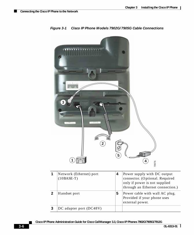
Chapter 3 Installing the Cisco IP PhoneConnecting the Cisco IP Phone to the Network
Figure 3-1 Cisco IP Phone Models 7902G/7905G Cable Connections
1 Network (Ethernet) port (10BASE-T)
4 Power supply with DC output connector. (Optional. Required only if power is not supplied through an Ethernet connection.)
2 Handset port 5 Power cable with wall AC plug. Provided if your phone uses external power.
3 DC adapter port (DC48V)
2
3
541
7997
6
3-6Cisco IP Phone Administration Guide for Cisco CallManager 3.3, Cisco IP Phones 7902G/7905G/7912G
OL-6313-01
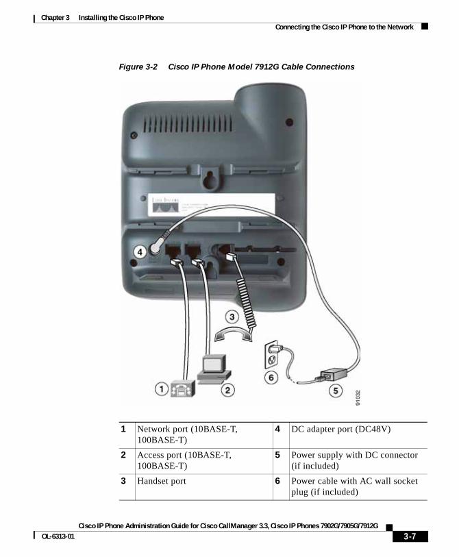
Chapter 3 Installing the Cisco IP PhoneConnecting the Cisco IP Phone to the Network
Figure 3-2 Cisco IP Phone Model 7912G Cable Connections
1 Network port (10BASE-T, 100BASE-T)
4 DC adapter port (DC48V)
2 Access port (10BASE-T, 100BASE-T)
5 Power supply with DC connector (if included)
3 Handset port 6 Power cable with AC wall socket plug (if included)
3-7Cisco IP Phone Administration Guide for Cisco CallManager 3.3, Cisco IP Phones 7902G/7905G/7912G
OL-6313-01
Chapter 3 Installing the Cisco IP PhoneMounting the Phone to the Wall
Mounting the Phone to the WallYou can mount the Cisco IP Phone on the wall by removing the footstand and using the mounting bracket on the back of the phone, or you can use special brackets available in a Cisco IP Phone wall mount kit. (A wall mount kit must be ordered separately from the phone.) If you attach the Cisco IP Phone to the wall using the standard footstand and not the wall mount kit, you need to supply the following tools and parts:
• Screwdriver
• Screws to secure the Cisco IP phone to the wall
Use the following procedure to mount the phone on the wall using its mounting bracket.
Before You Begin
To ensure that the handset attaches securely to a wall-mounted phone, remove the handset wall hook from the handset rest, rotate the hook 180 degrees, and reinsert the hook. Turning the hook exposes a lip on which the handset catches when the phone is vertical. For an illustrated procedure, see Installing the Wall Mount Kit for the Cisco IP Phone.
Procedure
Step 1 Remove the footstand from the phone.
Step 2 Modify the handset rest so that the handset remains on the ear-piece rest when the phone is vertically placed.
a. Remove the handset from the ear-piece rest.
b. Locate the tab (handset wall hook) at the base of the ear-piece rest.
c. Slide this tab out, rotate it 180 degrees (left to right), and reinsert it.
d. Place the handset on the ear-piece rest.
3-8Cisco IP Phone Administration Guide for Cisco CallManager 3.3, Cisco IP Phones 7902G/7905G/7912G
OL-6313-01
Chapter 3 Installing the Cisco IP PhoneVerifying the Phone Startup Process
Step 3 Insert two screws into a wall stud, matching them to the two screw holes on the back of the phone.
The keyholes fit standard phone jack mounts.
Step 4 Hang the phone on the wall.
Verifying the Phone Startup ProcessAfter the Cisco IP Phone has power connected to it, the phone begins its startup process by cycling through the following steps.
Cisco IP Phone 7902G
The phone uses a combination of the three LEDs (handset, Hold, and Menu buttons) to indicate the phone startup process. After several minutes, startup is complete and your phone is ready to use. When all of the LEDs are off, you will hear a dial tone when you lift the handset. If the phone does not start up successfully, see “Checking the Light Indicators on a Cisco IP Phone 7902G” section on page 6-11.
Cisco IP Phone Models 7905G/7912G
1. The handset light strip, Hold button, and Menu button flash on and off simultaneously.
2. The LCD screen displays the Cisco Systems, Inc., copyright screen.
3. The LCD screen displays these messages as the phone starts up:
• Configuring VLAN
• Configuring IP via DHCP
• Configuring CM List
• Opening address (where address is the IP address of the Cisco CallManager server)
• Registering
3-9Cisco IP Phone Administration Guide for Cisco CallManager 3.3, Cisco IP Phones 7902G/7905G/7912G
OL-6313-01

Chapter 3 Installing the Cisco IP PhoneConfiguring Startup Network Settings
4. The main LCD screen displays:
• Current date and time
• Primary directory number
• Softkeys
If the phone successfully passes through these stages, it has started up properly. Otherwise, see to the “Resolving Startup Problems” section on page 6-12.
Configuring Startup Network SettingsIf you are not using DHCP in your network, you must configure these network settings on the Cisco IP Phone after installing the phone on the network:
• IP address
• IP subnet mask
• Default gateway IP address
• Domain name
• DNS server IP address
• TFTP server IP address
Collect this information and follow the procedures defined in Chapter 4, “Configuring Network Settings on the Cisco IP Phone.”
3-10Cisco IP Phone Administration Guide for Cisco CallManager 3.3, Cisco IP Phones 7902G/7905G/7912G
OL-6313-01
Cisco IP Phone Administration Guide for Cisco CallManager 3OL-6313-01
C H A P T E R 4
Configuring Network Settings on the Cisco IP PhoneBecause the Cisco IP Phone is a network device, it includes many configurable network settings, which you might need to modify before the phone is accessible and functional for your users.
The following sections provide details about configuring and verifying these network settings:
• Configuring Methods, page 4-1
• Verifying Network Settings, page 4-4
• Modifying DHCP Settings, page 4-9
• Configuring IP Settings, page 4-15
• Modifying VLAN Settings, page 4-24
• Configuring TFTP Options, page 4-28
• Configuring CDP, page 4-32
Configuring MethodsOn the Cisco IP Phone 7902G, you can configure network settings using the phone’s web page or using its Interactive Voice Response (IVR) system. On the Cisco IP Phone models 7905G/7912G, you can configure network settings through the phone’s web page or using the Network Configuration screen on the phone.
4-1.3, Cisco IP Phones 7902G/7905G/7912G

Chapter 4 Configuring Network Settings on the Cisco IP PhoneConfiguring Methods
This chapter describes various methods you can use to configure most network settings for the Cisco IP Phone. For more information about web page configuration, and for information about IVR system configuration, see Appendix A, “Additional Configuration Methods, Parameters, and Procedures.”
Related Topics
• Accessing Network Configuration Settings from a Cisco IP Phone, page 4-2
• Accessing Network Configuration Settings through a Phone’s Web Page, page 4-3
Accessing Network Configuration Settings from a Cisco IP PhoneOn the Cisco IP Phone models 7905G/7912G, network configuration options in the Network Configuration Screen are locked by default to prevent users from making changes that could affect network connectivity for a phone.
When settings are inaccessible for modification, a locked padlock icon appears on the Network Configuration screen. An unlocked padlock icon appears on this screen when settings are unlocked and accessible for modification.
You must unlock the network configuration options from the Network Configuration screen before you can configure them. If a password has been specified for the phone, you must enter the password when unlocking network configuration options. (For more information about passwords, see Appendix A, “Additional Configuration Methods, Parameters, and Procedures.”)
Network configuration options are locked again automatically when you exit the Network Configuration Screen.
The unlocked padlock icon, shown below, appears in the margins of this chapter to indicate procedures that require you to unlock settings before modifying them.
Note On the Cisco IP Phone 7902G, network settings are not locked on the phone itself because these settings are accessed through the Phone Configuration web page or the Interactive Voice Response (IVR) system. See the specific instructions for the Cisco IP Phone 7902G in the sections that follow for more information.
4-2Cisco IP Phone Administration Guide for Cisco CallManager 3.3, Cisco IP Phones 7902G/7905G/7912G
OL-6313-01
Chapter 4 Configuring Network Settings on the Cisco IP PhoneConfiguring Methods
To unlock network settings on the Cisco IP Phone models 7905G/7912G, follow these steps.
Procedure
Step 1 Press the Menu button.
Step 2 Use the Navigation button to select Settings, and then press the Select softkey.
Step 3 Use the Navigation button to select Network Configuration, and then press the Select softkey.
Step 4 From the Network Configuration menu, press **#.
Step 5 If your phone displays “Enter Admin Password,” enter your password and then press the Enter softkey.
Step 6 Look at the upper-right portion of your LCD.
• Locked—The icon appears as a locked padlock.
• Unlocked—The icon appears as an unlocked padlock.
Accessing Network Configuration Settings through a Phone’s Web Page
The following sections include instructions for setting configuration options using a phone’s web page. To set configuration options in this way, you must first use the UIPassword parameter in the phone’s profile file to set up a password. If you do not set up a password, you will not be able to change network settings, and Apply will not be available.
For more information about the UIPassword parameter, see Table A-4 on page A-21.
4-3Cisco IP Phone Administration Guide for Cisco CallManager 3.3, Cisco IP Phones 7902G/7905G/7912G
OL-6313-01
Chapter 4 Configuring Network Settings on the Cisco IP PhoneVerifying Network Settings
Verifying Network SettingsOn Cisco IP Phone models 7905G/7912G, you can view detailed information about the current network settings of the phone. Use this information to troubleshoot or to make modifications.
For the Cisco IP Phone 7902G, you can obtain detailed information about current network settings from the Phone Configuration web page or through the IVR system.
To display current network settings for the Cisco IP Phone, follow these steps:
Using the Phone Configuration Web Page (Cisco IP Phone Models 7902G/7905G/7912G)
Procedure
Step 1 Open the Phone Configuration web page.
a. Open your web browser and enter the following URL, where IPaddress is the IP address of your phone
http://IPaddress
b. Press Enter.
The Phone Configuration web page appears.
Step 2 In the pane on the left:
a. Select Network Configuration to review network configuration information.
b. Select Network Statistics to view network statistics.
On the Cisco IP Phone 7902G, you can also review phone settings using the IVR system. See the “Using the Interactive Voice Response (IVR) System on the Cisco IP Phone 7902G” section on page A-22.
4-4Cisco IP Phone Administration Guide for Cisco CallManager 3.3, Cisco IP Phones 7902G/7905G/7912G
OL-6313-01
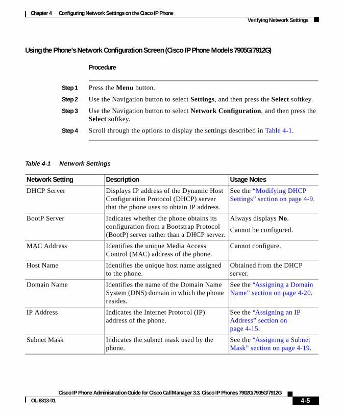
Chapter 4 Configuring Network Settings on the Cisco IP PhoneVerifying Network Settings
Using the Phone’s Network Configuration Screen (Cisco IP Phone Models 7905G/7912G)
Procedure
Step 1 Press the Menu button.
Step 2 Use the Navigation button to select Settings, and then press the Select softkey.
Step 3 Use the Navigation button to select Network Configuration, and then press the Select softkey.
Step 4 Scroll through the options to display the settings described in Table 4-1.
Table 4-1 Network Settings
Network Setting Description Usage Notes
DHCP Server Displays IP address of the Dynamic Host Configuration Protocol (DHCP) server that the phone uses to obtain IP address.
See the “Modifying DHCP Settings” section on page 4-9.
BootP Server Indicates whether the phone obtains its configuration from a Bootstrap Protocol (BootP) server rather than a DHCP server.
Always displays No.
Cannot be configured.
MAC Address Identifies the unique Media Access Control (MAC) address of the phone.
Cannot configure.
Host Name Identifies the unique host name assigned to the phone.
Obtained from the DHCP server.
Domain Name Identifies the name of the Domain Name System (DNS) domain in which the phone resides.
See the “Assigning a Domain Name” section on page 4-20.
IP Address Indicates the Internet Protocol (IP) address of the phone.
See the “Assigning an IP Address” section on page 4-15.
Subnet Mask Indicates the subnet mask used by the phone.
See the “Assigning a Subnet Mask” section on page 4-19.
4-5Cisco IP Phone Administration Guide for Cisco CallManager 3.3, Cisco IP Phones 7902G/7905G/7912G
OL-6313-01
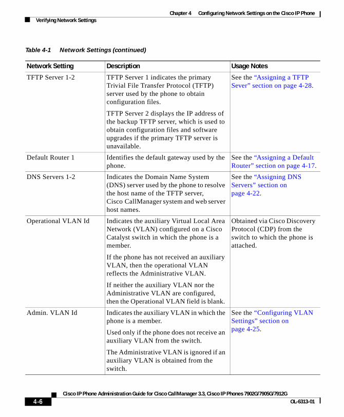
Chapter 4 Configuring Network Settings on the Cisco IP PhoneVerifying Network Settings
TFTP Server 1-2 TFTP Server 1 indicates the primary Trivial File Transfer Protocol (TFTP) server used by the phone to obtain configuration files.
TFTP Server 2 displays the IP address of the backup TFTP server, which is used to obtain configuration files and software upgrades if the primary TFTP server is unavailable.
See the “Assigning a TFTP Sever” section on page 4-28.
Default Router 1 Identifies the default gateway used by the phone.
See the “Assigning a Default Router” section on page 4-17.
DNS Servers 1-2 Indicates the Domain Name System (DNS) server used by the phone to resolve the host name of the TFTP server, Cisco CallManager system and web server host names.
See the “Assigning DNS Servers” section on page 4-22.
Operational VLAN Id Indicates the auxiliary Virtual Local Area Network (VLAN) configured on a Cisco Catalyst switch in which the phone is a member.
If the phone has not received an auxiliary VLAN, then the operational VLAN reflects the Administrative VLAN.
If neither the auxiliary VLAN nor the Administrative VLAN are configured, then the Operational VLAN field is blank.
Obtained via Cisco Discovery Protocol (CDP) from the switch to which the phone is attached.
Admin. VLAN Id Indicates the auxiliary VLAN in which the phone is a member.
Used only if the phone does not receive an auxiliary VLAN from the switch.
The Administrative VLAN is ignored if an auxiliary VLAN is obtained from the switch.
See the “Configuring VLAN Settings” section on page 4-25.
Table 4-1 Network Settings (continued)
Network Setting Description Usage Notes
4-6Cisco IP Phone Administration Guide for Cisco CallManager 3.3, Cisco IP Phones 7902G/7905G/7912G
OL-6313-01
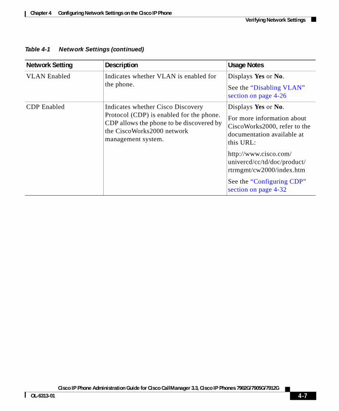
Chapter 4 Configuring Network Settings on the Cisco IP PhoneVerifying Network Settings
VLAN Enabled Indicates whether VLAN is enabled for the phone.
Displays Yes or No.
See the “Disabling VLAN” section on page 4-26
CDP Enabled Indicates whether Cisco Discovery Protocol (CDP) is enabled for the phone. CDP allows the phone to be discovered by the CiscoWorks2000 network management system.
Displays Yes or No.
For more information about CiscoWorks2000, refer to the documentation available at this URL:
http://www.cisco.com/univercd/cc/td/doc/product/rtrmgmt/cw2000/index.htm
See the “Configuring CDP” section on page 4-32
Table 4-1 Network Settings (continued)
Network Setting Description Usage Notes
4-7Cisco IP Phone Administration Guide for Cisco CallManager 3.3, Cisco IP Phones 7902G/7905G/7912G
OL-6313-01
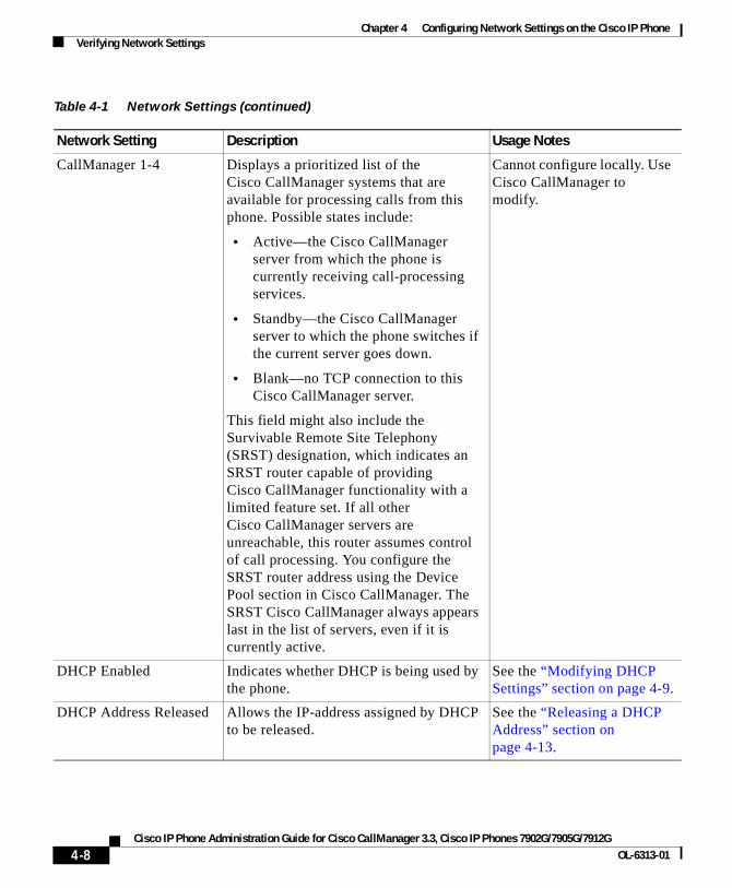
Chapter 4 Configuring Network Settings on the Cisco IP PhoneVerifying Network Settings
CallManager 1-4 Displays a prioritized list of the Cisco CallManager systems that are available for processing calls from this phone. Possible states include:
• Active—the Cisco CallManager server from which the phone is currently receiving call-processing services.
• Standby—the Cisco CallManager server to which the phone switches if the current server goes down.
• Blank—no TCP connection to this Cisco CallManager server.
This field might also include the Survivable Remote Site Telephony (SRST) designation, which indicates an SRST router capable of providing Cisco CallManager functionality with a limited feature set. If all other Cisco CallManager servers are unreachable, this router assumes control of call processing. You configure the SRST router address using the Device Pool section in Cisco CallManager. The SRST Cisco CallManager always appears last in the list of servers, even if it is currently active.
Cannot configure locally. Use Cisco CallManager to modify.
DHCP Enabled Indicates whether DHCP is being used by the phone.
See the “Modifying DHCP Settings” section on page 4-9.
DHCP Address Released Allows the IP-address assigned by DHCP to be released.
See the “Releasing a DHCP Address” section on page 4-13.
Table 4-1 Network Settings (continued)
Network Setting Description Usage Notes
4-8Cisco IP Phone Administration Guide for Cisco CallManager 3.3, Cisco IP Phones 7902G/7905G/7912G
OL-6313-01
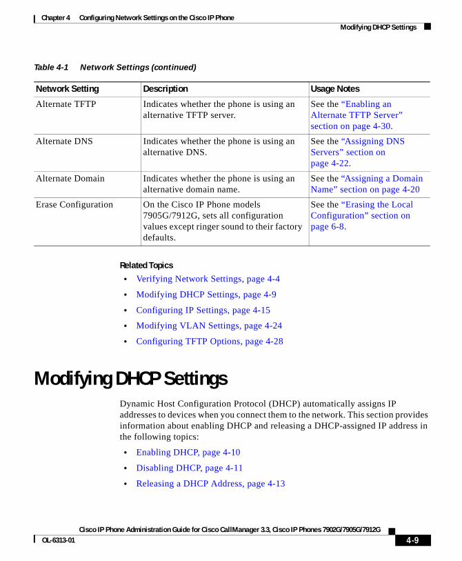
Chapter 4 Configuring Network Settings on the Cisco IP PhoneModifying DHCP Settings
Related Topics
• Verifying Network Settings, page 4-4
• Modifying DHCP Settings, page 4-9
• Configuring IP Settings, page 4-15
• Modifying VLAN Settings, page 4-24
• Configuring TFTP Options, page 4-28
Modifying DHCP SettingsDynamic Host Configuration Protocol (DHCP) automatically assigns IP addresses to devices when you connect them to the network. This section provides information about enabling DHCP and releasing a DHCP-assigned IP address in the following topics:
• Enabling DHCP, page 4-10
• Disabling DHCP, page 4-11
• Releasing a DHCP Address, page 4-13
Alternate TFTP Indicates whether the phone is using an alternative TFTP server.
See the “Enabling an Alternate TFTP Server” section on page 4-30.
Alternate DNS Indicates whether the phone is using an alternative DNS.
See the “Assigning DNS Servers” section on page 4-22.
Alternate Domain Indicates whether the phone is using an alternative domain name.
See the “Assigning a Domain Name” section on page 4-20
Erase Configuration On the Cisco IP Phone models 7905G/7912G, sets all configuration values except ringer sound to their factory defaults.
See the “Erasing the Local Configuration” section on page 6-8.
Table 4-1 Network Settings (continued)
Network Setting Description Usage Notes
4-9Cisco IP Phone Administration Guide for Cisco CallManager 3.3, Cisco IP Phones 7902G/7905G/7912G
OL-6313-01
Chapter 4 Configuring Network Settings on the Cisco IP PhoneModifying DHCP Settings
Enabling DHCP
Cisco IP Phones enable DHCP by default, but you can reset the protocol if it becomes disabled.
Using the Phone Configuration Web Page (Cisco IP Phone Models 7902G/7905G/7912G)
Procedure
Step 1 Open the Phone Configuration web page.
a. Open your web browser and enter the following URL, where IPaddress is the IP address of your phone
http://IPaddress
b. Press Enter.
The Phone Configuration web page appears.
Step 2 In the pane on the left under Change Configuration, click Network Parameters.
You may be prompted to enter a password.
The Network Parameters web page appears.
Step 3 To enable DHCP, enter 1 in the DHCP field and click Apply.
On the Cisco IP Phone 7902G, you can also review phone settings using the IVR system. See the “Using the Interactive Voice Response (IVR) System on the Cisco IP Phone 7902G” section on page A-22.
Using the Phone’s Network Configuration Screen (Cisco IP Phone Models 7905G/7912G)
Procedure
Step 1 Press the Menu button.
Step 2 Use the Navigation button to select Settings, and then press the Select softkey.
Step 3 From the Settings menu, use the Navigation button to select Network Configuration, and then press the Select softkey.
4-10Cisco IP Phone Administration Guide for Cisco CallManager 3.3, Cisco IP Phones 7902G/7905G/7912G
OL-6313-01
Chapter 4 Configuring Network Settings on the Cisco IP PhoneModifying DHCP Settings
Step 4 From the Network Configuration menu, press **#.
If your phone displays “Enter Admin Password,” enter your password and then press the Enter softkey.
Make sure that an unlocked padlock icon appears in the upper-right corner of your LCD.
Step 5 Scroll to DHCP Enabled.
If DHCP is disabled, the option appears as
DHCP Enabled NO
Step 6 Press the Yes softkey to enable DHCP.
Step 7 Press Save.
Related Topics
• Disabling DHCP, page 4-11
• Releasing a DHCP Address, page 4-13
• Configuring IP Settings, page 4-15
Disabling DHCP
If you do not use DHCP in your network, use this procedure to disable DHCP before manually assigning IP addresses to Cisco IP phones.
Note Procedures involved in configuring IP settings or TFTP options cannot be completed when DHCP is enabled in your network.
4-11Cisco IP Phone Administration Guide for Cisco CallManager 3.3, Cisco IP Phones 7902G/7905G/7912G
OL-6313-01
Chapter 4 Configuring Network Settings on the Cisco IP PhoneModifying DHCP Settings
Using the Phone Configuration Web Page (Cisco IP Phone Models 7902G/7905G/7912G)
Procedure
Step 1 Open the Phone Configuration web page.
a. Open your web browser and enter the following URL, where IPaddress is the IP address of your phone:
http://IPaddress
b. Press Enter.
The Phone Configuration web page appears.
Step 2 In the pane on the left under Change Configuration, click Network Parameters.
You may be prompted to enter a password.
The Network Parameters web page appears.
Step 3 To disable DHCP, enter 0 in the DHCP field and click Apply.
On the Cisco IP Phone 7902G, you can also review phone settings using the IVR system. See the “Using the Interactive Voice Response (IVR) System on the Cisco IP Phone 7902G” section on page A-22.
Using the Phone’s Network Configuration Screen (Cisco IP Phone Models 7905G/7912G)
Procedure
Step 1 Press the Menu button.
Step 2 Use the Navigation button to select Settings, and then press the Select softkey.
Step 3 From the Settings menu, use the Navigation button to select Network Configuration, and then press the Select softkey.
Step 4 From the Network Configuration menu, press **#.
If your phone displays “Enter Admin Password”, enter your password and then press the Enter softkey.
Make sure that an unlocked padlock icon appears in the upper-right corner of your LCD.
4-12Cisco IP Phone Administration Guide for Cisco CallManager 3.3, Cisco IP Phones 7902G/7905G/7912G
OL-6313-01

Chapter 4 Configuring Network Settings on the Cisco IP PhoneModifying DHCP Settings
Step 5 Scroll to DHCP Enabled.
If DHCP is enabled, the option appears as
DHCP Enabled YES
Step 6 Press the No softkey to disable DHCP.
Step 7 Press Save.
Related Topics
• Enabling DHCP, page 4-10
• Releasing a DHCP Address, page 4-13
• Configuring IP Settings, page 4-15
Releasing a DHCP Address
When moving the phone to a new network segment, you should first release the DHCP address. You cannot perform this procedure from the Phone Configuration web page. Instead, you must use the IVR system (for the Cisco IP Phone 7902G) or the phone’s Network Configuration Screen (for the Cisco IP Phone models 7902G/7912G).
Using the IVR System (Cisco IP Phone 7902G)
Step 1 Lift the handset, then press and hold the Menu button for about 3 seconds.
Step 2 Press 4444 to release the DHCP address.
Step 3 Hang up the phone. The phone resets.
4-13Cisco IP Phone Administration Guide for Cisco CallManager 3.3, Cisco IP Phones 7902G/7905G/7912G
OL-6313-01

Chapter 4 Configuring Network Settings on the Cisco IP PhoneModifying DHCP Settings
Using the Phone’s Network Configuration Screen (Cisco IP Phone Models 7905G/7912G)
Procedure
Step 1 Press the Menu button.
Step 2 Use the Navigation button to select Settings, and then press the Select softkey.
Step 3 From the Settings menu, use the Navigation button to select Network Configuration, and then press the Select softkey.
Step 4 From the Network Configuration menu, press **#.
If your phone displays “Enter Admin Password,” enter your password and then press the Enter softkey.
Make sure that an unlocked padlock icon appears in the upper-right corner of your LCD.
Step 5 Scroll to DHCP Address Released.
If the DHCP address is currently assigned, the option appears as
DHCP Address Released NO
Step 6 Press the Yes softkey to release the DHCP-assigned IP address.
Step 7 Press Save.
The phone remains in an idle state, without an IP address assigned, until you do one of the following actions:
• Manually assign an IP address.
• Set DHCP Address Released back to No.
• Power cycle the phone, which enables all default settings, including enabling DHCP.
Related Topics
• Enabling DHCP, page 4-10
• Disabling DHCP, page 4-11
• Configuring IP Settings, page 4-15
4-14Cisco IP Phone Administration Guide for Cisco CallManager 3.3, Cisco IP Phones 7902G/7905G/7912G
OL-6313-01
Chapter 4 Configuring Network Settings on the Cisco IP PhoneConfiguring IP Settings
Configuring IP SettingsUse these guidelines when manually configuring the IP settings:
• You can use 0.0.0.0 for the subnet mask only if the default gateway is also 0.0.0.0.
• Ensure the TFTP server has an IP address.
• Ensure the default gateway IP address is on the same subnet as the host IP address.
Note Procedures involved in configuring IP settings or TFTP options cannot be completed when DHCP is enabled in your network.
This section covers the following topics:
• Assigning an IP Address, page 4-15
• Assigning a Default Router, page 4-17
• Assigning a Subnet Mask, page 4-19
• Assigning a Domain Name, page 4-20
• Assigning DNS Servers, page 4-22
Assigning an IP Address
The IP address is the unique logical address identifying each host computer, or node, on a TCP/IP network. An IP address is a 32-bit number expressed as four decimal numbers from 0 to 255 separated by periods.
Before you can assign an IP address, you must disable DHCP. For instructions, see the “Disabling DHCP” section on page 4-11.
4-15Cisco IP Phone Administration Guide for Cisco CallManager 3.3, Cisco IP Phones 7902G/7905G/7912G
OL-6313-01
Chapter 4 Configuring Network Settings on the Cisco IP PhoneConfiguring IP Settings
Using the Phone Configuration Web Page (Cisco IP Phone Models 7902G/7905G/7912G)
Procedure
Step 1 Open the Phone Configuration web page.
a. Open your web browser and enter the following URL, where IPaddress is the IP address of your phone:
http://IPaddress
b. Press Enter.
The Phone Configuration web page appears.
Step 2 In the pane on the left under Change Configuration, click Network Parameters.
You may be prompted to enter a password.
The Network Parameters web page appears.
Step 3 To set the IP address, enter an address in the StaticIP field and click Apply.
On the Cisco IP Phone 7902G, you can also review phone settings using the IVR system. See the “Using the Interactive Voice Response (IVR) System on the Cisco IP Phone 7902G” section on page A-22.
Using the Phone’s Network Configuration Screen (Cisco IP Phone Models 7905G/7912G)
Procedure
Step 1 Press the Menu button.
Step 2 Use the Navigation button to select Settings, and then press the Select softkey.
Step 3 From the Settings menu, use the Navigation button to select Network Configuration, and then press the Select softkey.
Step 4 From the Network Configuration menu, press **#.
If your phone displays “Enter Admin Password,” enter your password and then press the Enter softkey.
Make sure that an unlocked padlock icon appears in the upper-right corner of your LCD.
4-16Cisco IP Phone Administration Guide for Cisco CallManager 3.3, Cisco IP Phones 7902G/7905G/7912G
OL-6313-01
Chapter 4 Configuring Network Settings on the Cisco IP PhoneConfiguring IP Settings
Step 5 Scroll to IP Address.
Step 6 Press the Edit softkey.
Step 7 Use the buttons on the keypad to enter the new IP address, using the * key on the keypad to enter periods.
Use the << softkey to correct any mistakes.
Step 8 Press Validat.
Step 9 Press Save.
Assigning a Default Router
If you manually assign an IP address to the Cisco IP Phone, you must indicate the default router to be used. The default router provides connectivity to the IP network beyond the subnet to which the phone belongs.
Before you can assign a default router, you must disable DHCP. For instructions, see the “Disabling DHCP” section on page 4-11.
Using the Phone Configuration Web Page (Cisco IP Phone Models 7902G/7905G/7912G)
Procedure
Step 1 Open the Phone Configuration web page.
a. Open your web browser and enter the following URL, where IPaddress is the IP address of your phone
http://IPaddress
b. Press Enter.
The Phone Configuration web page appears.
Step 2 In the pane on the left under Change Configuration, click Network Parameters.
You may be prompted to enter a password.
The Network Parameters web page appears.
4-17Cisco IP Phone Administration Guide for Cisco CallManager 3.3, Cisco IP Phones 7902G/7905G/7912G
OL-6313-01
Chapter 4 Configuring Network Settings on the Cisco IP PhoneConfiguring IP Settings
Step 3 To set the route address, enter an address in the StaticRoute field and click Apply.
On the Cisco IP Phone 7902G, you can also review phone settings using the IVR system. See the “Using the Interactive Voice Response (IVR) System on the Cisco IP Phone 7902G” section on page A-22.
Using the Phone’s Network Configuration Screen (Cisco IP Phone Models 7905G/7912G)
Procedure
Step 1 Press the Menu button.
Step 2 Use the Navigation button to select Settings, and then press the Select softkey.
Step 3 From the Settings menu, use the Navigation button to select Network Configuration, and then press the Select softkey.
Step 4 From the Network Configuration menu, press **#.
If your phone displays “Enter Admin Password,” enter your password and then press the Enter softkey.
Make sure that an unlocked padlock icon appears in the upper-right corner of your LCD.
Step 5 Scroll to Default Router.
Step 6 Press the Edit softkey.
Step 7 Use the buttons on the keypad to enter the new IP address, using the * key on the keypad to enter periods.
Use the << softkey to correct any mistakes.
Step 8 Press Validat.
Step 9 Press Save.
4-18Cisco IP Phone Administration Guide for Cisco CallManager 3.3, Cisco IP Phones 7902G/7905G/7912G
OL-6313-01
Chapter 4 Configuring Network Settings on the Cisco IP PhoneConfiguring IP Settings
Assigning a Subnet Mask
The subnet mask is used to partition the IP address into a network and a host identifier. The subnet mask is used to mask a portion of the IP address so that TCP/IP can distinguish the network ID from the host ID.
Before you can assign a subnet mask, you must disable DHCP. For instructions, see the “Disabling DHCP” section on page 4-11.
Using the Phone Configuration Web Page (Cisco IP Phone Models 7902G/7905G/7912G)
Procedure
Step 1 Open the Phone Configuration web page.
a. Open your web browser and enter the following URL, where IPaddress is the IP address of your phone
http://IPaddress
b. Press Enter.
The Phone Configuration web page appears.
Step 2 In the pane on the left under Change Configuration, click Network Parameters.
You may be prompted to enter a password.
The Network Parameters web page appears.
Step 3 To set the subnet mask, enter an address in the StaticNetMask field and click Apply.
On the Cisco IP Phone 7902G, you can also review phone settings using the IVR system. See the “Using the Interactive Voice Response (IVR) System on the Cisco IP Phone 7902G” section on page A-22.
4-19Cisco IP Phone Administration Guide for Cisco CallManager 3.3, Cisco IP Phones 7902G/7905G/7912G
OL-6313-01

Chapter 4 Configuring Network Settings on the Cisco IP PhoneConfiguring IP Settings
Using the Phone’s Network Configuration Screen (Cisco IP Phone Models 7905G/7912G)
Procedure
Step 1 Press the Menu button.
Step 2 Use the Navigation button to select Settings, and then press the Select softkey.
Step 3 From the Settings menu, use the Navigation button to select Network Configuration, and then press the Select softkey.
Step 4 From the Network Configuration menu, press **#.
If your phone displays “Enter Admin Password,” enter your password and then press the Enter softkey.
Make sure that an unlocked padlock icon appears in the upper-right corner of your LCD.
Step 5 Scroll to Subnet Mask.
Step 6 Press the Edit softkey.
Step 7 Use the buttons on the keypad to enter the new IP address, using the * key on the keypad to enter periods.
Use the << softkey to correct any mistakes.
Step 8 Press Validat.
Step 9 Press Save.
Assigning a Domain Name
The domain name is the name of the Domain Name System (DNS) domain in which the phone is located. DNS is a hierarchical name for TCP/IP host computers that provides standard naming conventions.
Before assigning a domain name, verify that you have a DNS in your network.
4-20Cisco IP Phone Administration Guide for Cisco CallManager 3.3, Cisco IP Phones 7902G/7905G/7912G
OL-6313-01
Chapter 4 Configuring Network Settings on the Cisco IP PhoneConfiguring IP Settings
Using the Phone Configuration Web Page (Cisco IP Phone Models 7902G/7905G/7912G)
Procedure
Step 1 Open the Phone Configuration web page.
a. Open your web browser and enter the following URL, where IPaddress is the IP address of your phone
http://IPaddress
b. Press Enter.
The Phone Configuration web page appears.
Step 2 In the pane on the left under Change Configuration, click Network Parameters.
You may be prompted to enter a password.
The Network Parameters web page appears.
Step 3 To set the domain name, enter a domain name in the Domain field and click Apply.
On the Cisco IP Phone 7902G, you can also review phone settings using the IVR system. See the “Using the Interactive Voice Response (IVR) System on the Cisco IP Phone 7902G” section on page A-22.
Using the Phone’s Network Configuration Screen (Cisco IP Phone Models 7905G/7912G)
Procedure
Step 1 Press the Menu button.
Step 2 Use the Navigation button to select Settings, and then press the Select softkey.
Step 3 From the Settings menu, use the Navigation button to select Network Configuration, and then press the Select softkey.
4-21Cisco IP Phone Administration Guide for Cisco CallManager 3.3, Cisco IP Phones 7902G/7905G/7912G
OL-6313-01
Chapter 4 Configuring Network Settings on the Cisco IP PhoneConfiguring IP Settings
Step 4 From the Network Configuration menu, press **#.
If your phone displays “Enter Admin Password,” enter your password and then press the Enter softkey.
Make sure that an unlocked padlock icon appears in the upper-right corner of your LCD.
Step 5 Scroll to Alternate Domain.
Step 6 If the option appears as
Alternate Domain NO
Press the Yes softkey.
Step 7 Scroll to Domain Name.
Step 8 Press the Edit softkey.
Step 9 Use the buttons on the keypad to enter the new domain name, using the * key on the keypad to enter periods.
To enter letters, use the numbers associated with a particular letter. For example, the 2 key has the letters ABC. For a lower case “a,” press 2 once. Press the 2 key repeatedly to scroll through the available letters and numbers. Pause after the selected letter appears on the screen.
Use the << softkey to correct any mistakes.
Step 10 Press Validat.
Step 11 Press Save.
Assigning DNS Servers
The DNS setting on the Cisco IP Phone allows users to specify remote computers by host names, which are character strings with some mnemonic value, rather than by using IP addresses, which are simply strings of numbers.
The phones use DNS to resolve the host name of TFTP servers, Cisco CallManager systems, and web server host names when the system is configured to use names rather than IP addresses.
4-22Cisco IP Phone Administration Guide for Cisco CallManager 3.3, Cisco IP Phones 7902G/7905G/7912G
OL-6313-01
Chapter 4 Configuring Network Settings on the Cisco IP PhoneConfiguring IP Settings
Using the Phone Configuration Web Page (Cisco IP Phone Models 7902G/7905G/7912G)
Procedure
Step 1 Open the Phone Configuration web page.
a. Open your web browser and enter the following URL, where IPaddress is the IP address of your phone
http://IPaddress
b. Press Enter.
The Phone Configuration web page appears.
Step 2 In the pane on the left under Change Configuration, click Network Parameters.
You may be prompted to enter a password.
The Network Parameters web page appears.
Step 3 To set the DNS servers:
a. To set DNS Server1, in the DNSServer1 field enter an address and click Apply.
b. To set DNS Server2, in the DNSServer2 field enter an address and click Apply.
On the Cisco IP Phone 7902G, you can also review phone settings using the IVR system. See the “Using the Interactive Voice Response (IVR) System on the Cisco IP Phone 7902G” section on page A-22.
Using the Phone’s Network Configuration Screen (Cisco IP Phone Models 7905G/7912G)
Procedure
Step 1 Press the Menu button.
Step 2 Use the Navigation button to select Settings, and then press the Select softkey.
Step 3 From the Settings menu, use the Navigation button to select Network Configuration, and then press the Select softkey.
4-23Cisco IP Phone Administration Guide for Cisco CallManager 3.3, Cisco IP Phones 7902G/7905G/7912G
OL-6313-01
Chapter 4 Configuring Network Settings on the Cisco IP PhoneModifying VLAN Settings
Step 4 From the Network Configuration menu, press **#.
If your phone displays “Enter Admin Password,” enter your password and then press the Enter softkey.
Make sure that an unlocked padlock icon appears in the upper-right corner of your LCD.
Step 5 Scroll to Alternate DNS.
Step 6 If the option appears as
Alternate DNS NO
Press the Yes softkey.
Step 7 Scroll to DNS Server 1.
Step 8 Press the Edit softkey.
Step 9 Use the buttons on the keypad to enter the new domain name, using the * key on the keypad to enter periods.
Use the << softkey to correct any mistakes.
Step 10 Scroll to DNS Server 2 to add a backup DNS server.
Step 11 Press Validat.
Step 12 Press Save.
Modifying VLAN SettingsYou can change the administrative VLAN used by the Cisco IP Phone and, on the Cisco IP Phone models 7905G/7912, you can disable or enable VLAN manually.
This section covers the following topics:
• Configuring VLAN Settings, page 4-25
• Disabling VLAN, page 4-26
4-24Cisco IP Phone Administration Guide for Cisco CallManager 3.3, Cisco IP Phones 7902G/7905G/7912G
OL-6313-01
Chapter 4 Configuring Network Settings on the Cisco IP PhoneModifying VLAN Settings
Configuring VLAN Settings
If you have an auxiliary VLAN assigned on the Cisco Catalyst switch, that setting overrides any changes made on the phone.
Using the Phone Configuration Web Page (Cisco IP Phone Models 7902G/7905G/7912G)
Procedure
Step 1 Open the Phone Configuration web page.
a. Open your web browser and enter the following URL, where IPaddress is the IP address of your phone
http://IPaddress
b. Press Enter.
The Phone Configuration web page appears.
Step 2 In the pane on the left under Change Configuration, click Network Parameters.
You may be prompted to enter a password.
The Network Parameters web page appears.
Step 3 In the VLANSetting field, enter a VLAN ID into bits 18–29 and click Apply.
For more information about this field, see the VLANSetting parameter in Table A-1 on page A-12.
On the Cisco IP Phone 7902G, you can also review phone settings using the IVR system. See the “Using the Interactive Voice Response (IVR) System on the Cisco IP Phone 7902G” section on page A-22.
Using the Phone’s Network Configuration Screen (Cisco IP Phone Models 7905G/7912G)
Procedure
Step 1 Press the Menu button.
Step 2 Use the Navigation button to select Settings, and then press the Select softkey.
4-25Cisco IP Phone Administration Guide for Cisco CallManager 3.3, Cisco IP Phones 7902G/7905G/7912G
OL-6313-01
Chapter 4 Configuring Network Settings on the Cisco IP PhoneModifying VLAN Settings
Step 3 From the Settings menu, use the Navigation button to select Network Configuration, and then press the Select softkey.
Step 4 From the Network Configuration menu, press **#.
If your phone displays “Enter Admin Password,” enter your password and then press the Enter softkey.
Make sure that an unlocked padlock icon appears in the upper-right corner of your LCD.
Step 5 Scroll to Admin. VLAN Id.
Step 6 Press the Edit softkey.
Step 7 Use the buttons on the keypad to enter the new Admin VLAN setting.
Use the << softkey to correct any mistakes.
Step 8 Press Validat.
Step 9 Press Save.
Disabling VLAN
You can disable or enable VLAN manually.
Using the Phone Configuration Web Page (Cisco IP Phone Models 7902G/7905G/7912G)
Procedure
Step 1 Open the Phone Configuration web page.
a. Open your web browser and enter the following URL, where IPaddress is the IP address of your phone
http://IPaddress
b. Press Enter.
The Phone Configuration web page appears.
4-26Cisco IP Phone Administration Guide for Cisco CallManager 3.3, Cisco IP Phones 7902G/7905G/7912G
OL-6313-01
Chapter 4 Configuring Network Settings on the Cisco IP PhoneModifying VLAN Settings
Step 2 In the pane on the left under Change Configuration, click Network Parameters.
You may be prompted to enter a password.
The Network Parameters web page appears.
Step 3 To enable VLAN, in the OpFlags field, change bit 5 to 0 (zero).
To disable VLAN, in the OpFlags field, change bit 5 to 1.
For more information about this field, see OpFlags parameter in Table A-1 on page A-12.
Step 4 Click Apply.
Using the Phone’s Network Configuration Screen (Cisco IP Phone Models 7905G/7912G)
Procedure
Step 1 Press the Menu button.
Step 2 Use the Navigation button to select Settings, and then press the Select softkey.
Step 3 From the Settings menu, use the Navigation button to select Network Configuration, and then press the Select softkey.
Step 4 From the Network Configuration menu, press **#.
If your phone displays “Enter Admin Password,” enter your password and then press the Enter softkey.
Make sure that an unlocked padlock icon appears in the upper-right corner of your LCD.
Step 5 Scroll to VLAN Enabled.
If VLAN is enabled, the option appears as
VLAN Enabled YES
Step 6 Press the No softkey to disable VLAN.
Step 7 Press Save.
4-27Cisco IP Phone Administration Guide for Cisco CallManager 3.3, Cisco IP Phones 7902G/7905G/7912G
OL-6313-01
Chapter 4 Configuring Network Settings on the Cisco IP PhoneConfiguring TFTP Options
Configuring TFTP OptionsIf you do not use DHCP to direct the Cisco IP Phone to a TFTP server, you must manually assign one. You can also assign an alternative TFTP server to use instead of the one assigned by DHCP. On the Cisco IP Phone 7902G, you can manually enable or disable TFTP.
This section covers these topics:
• Assigning a TFTP Sever, page 4-28
• Enabling an Alternate TFTP Server, page 4-30
Assigning a TFTP Sever
If you are not using DHCP in your network, and you want to change this setting, you must manually assign the TFTP server to the phone.
Before you can manually assign a TFTP server, you must enable an alternate TFTP server. For instructions, see the “Enabling an Alternate TFTP Server” section on page 4-30.
Using the Phone Configuration Web Page (Cisco IP Phone Models 7902G/7905G/7912G)
Procedure
Step 1 Open the Phone Configuration web page.
a. Open your web browser and enter the following URL, where IPaddress is the IP address of your phone
http://IPaddress
b. Press Enter.
The Phone Configuration web page appears.
Step 2 In the pane on the left under Change Configuration, click Network Parameters.
You may be prompted to enter a password.
The Network Parameters web page appears.
4-28Cisco IP Phone Administration Guide for Cisco CallManager 3.3, Cisco IP Phones 7902G/7905G/7912G
OL-6313-01
Chapter 4 Configuring Network Settings on the Cisco IP PhoneConfiguring TFTP Options
Step 3 To set the TFTP servers:
a. To set TFTP Server1, in the TFTPServer1 field enter an address and click Apply.
b. To set TFTP Server2, in the TFTPServer2 field enter an address and click Apply.
Using the Phone’s Network Configuration Screen (Cisco IP Phone Models 7905G/7912G)
Procedure
Step 1 Press the Menu button.
Step 2 Use the Navigation button to select Settings, and then press the Select softkey.
Step 3 From the Settings menu, use the Navigation button to select Network Configuration, and then press the Select softkey.
Step 4 From the Network Configuration menu, press **#.
If your phone displays “Enter Admin Password,” enter your password and then press the Enter softkey.
Make sure that an unlocked padlock icon appears in the upper-right corner of your LCD.
Step 5 Scroll to TFTP Server 1.
Step 6 Press the Edit softkey.
Step 7 Use the buttons on the keypad to enter a new TFTP server address, using the * key on the keypad to enter periods.
Use the << softkey to correct any mistakes.
Step 8 Press Validat.
Step 9 Scroll to TFTP Server 2 to add a backup TFTP server.
Step 10 Press Save.
4-29Cisco IP Phone Administration Guide for Cisco CallManager 3.3, Cisco IP Phones 7902G/7905G/7912G
OL-6313-01
Chapter 4 Configuring Network Settings on the Cisco IP PhoneConfiguring TFTP Options
Enabling an Alternate TFTP Server
If you are using DHCP, but you want to override the TFTP address that the phone received through DHCP, enable an alternate TFTP Server.
Using the Phone’s Network Configuration Screen (Cisco IP Phone Models 7905G/7912G)
Procedure
Step 1 Press the Menu button.
Step 2 Use the Navigation button to select Settings, and then press the Select softkey.
Step 3 From the Settings menu, use the Navigation button to select Network Configuration, and then press the Select softkey.
Step 4 From the Network Configuration menu, press **#.
If your phone displays “Enter Admin Password,” enter your password and then press the Enter softkey.
Make sure that an unlocked padlock icon appears in the upper-right corner of your LCD.
Step 5 Scroll to Alternate TFTP.
If the phone is not using an alternative TFTP server, the option appears as
Alternate TFTP NO
Step 6 Press the Yes softkey.
Step 7 Scroll to TFTP Server 1.
Step 8 Press the Edit softkey.
Step 9 Use the buttons on the keypad to enter the new Alternative TFTP Server address, using the * key on the keypad to enter periods.
Step 10 Press Validat.
Step 11 Scroll to TFTP Server 2 to add a backup TFTP server.
Step 12 Press Save.
4-30Cisco IP Phone Administration Guide for Cisco CallManager 3.3, Cisco IP Phones 7902G/7905G/7912G
OL-6313-01
Chapter 4 Configuring Network Settings on the Cisco IP PhoneConfiguring TFTP Options
Assigning a Backup TFTP Server
TFTP Server 2 displays the IP address of the backup TFTP server. This server is used to obtain configuration files and software upgrades if the primary TFTP server is unavailable.
Before you can assign a backup TFTP server, the Alternate TFTP setting must be set to Yes.
This procedure does not apply to the Cisco IP Phone 7902G.
Using the Phone’s Network Configuration Screen (Cisco IP Phone Models 7905G/7912G)
Procedure
Step 1 Press the Menu button.
Step 2 Use the Navigation button to select Settings, and then press the Select softkey.
Step 3 From the Settings menu, use the Navigation button to select Network Configuration, and then press the Select softkey.
Step 4 From the Network Configuration menu, press **#.
If your phone displays “Enter Admin Password,” enter your password and then press the Enter softkey.
Make sure that an unlocked padlock icon appears in the upper-right corner of your LCD.
Step 5 Scroll to TFTP Server 2.
Step 6 Press the Edit softkey.
Step 7 Use the buttons on the keypad to enter the new Alternative TFTP Server address, using the * key on the keypad to enter periods.
Use the << softkey to correct any mistakes.
Step 8 Press the Validat softkey.
Step 9 Press Save.
4-31Cisco IP Phone Administration Guide for Cisco CallManager 3.3, Cisco IP Phones 7902G/7905G/7912G
OL-6313-01
Chapter 4 Configuring Network Settings on the Cisco IP PhoneConfiguring CDP
Configuring CDPYou can disable or enable Cisco Discovery Protocol (CDP). CDP allows the phone to be discovered by the CiscoWorks2000 network management system.
For more information about CiscoWorks2000, refer to the documentation available at this URL:
http://www.cisco.com/univercd/cc/td/doc/product/rtrmgmt/cw2000/index.htm
Using the Phone Configuration Web Page (Cisco IP Phone Models 7902G/7905G/7912G)
Procedure
Step 1 Open the Phone Configuration web page.
a. Open your web browser and enter the following URL, where IPaddress is the IP address of your phone
http://IPaddress
b. Press Enter.
The Phone Configuration web page appears.
Step 2 In the pane on the left under Change Configuration, click Network Parameters.
You may be prompted to enter a password.
The Network Parameters web page appears.
Step 3 In the OpFlags field,
a. To enable CDP, change bit 6 to a zero (0).
b. To disable CDP, change bit 6 to a 1.
Using the Phone’s Network Configuration Screen (Cisco IP Phone Models 7905G/7912G)
Procedure
Step 1 Press the Menu button.
Step 2 Use the Navigation button to select Settings, and then press the Select softkey.
4-32Cisco IP Phone Administration Guide for Cisco CallManager 3.3, Cisco IP Phones 7902G/7905G/7912G
OL-6313-01
Chapter 4 Configuring Network Settings on the Cisco IP PhoneConfiguring CDP
Step 3 From the Settings menu, use the Navigation button to select Network Configuration, and then press the Select softkey.
Step 4 From the Network Configuration menu, press **#.
If your phone displays “Enter Admin Password,” enter your password and then press the Enter softkey.
Make sure that an unlocked padlock icon appears in the upper-right corner of your LCD.
Step 5 Scroll to CDP Enabled.
If CDP is enabled, the option appears as
CDP Enabled Yes
Step 6 Press the No softkey to disable CDP.
Step 7 Press Save.
4-33Cisco IP Phone Administration Guide for Cisco CallManager 3.3, Cisco IP Phones 7902G/7905G/7912G
OL-6313-01

Chapter 4 Configuring Network Settings on the Cisco IP PhoneConfiguring CDP
4-34Cisco IP Phone Administration Guide for Cisco CallManager 3.3, Cisco IP Phones 7902G/7905G/7912G
OL-6313-01
Cisco IP Phone Administration Guide for Cisco CallManager 3OL-6313-01
C H A P T E R 5
Configuring Users, Features, and ServicesAfter you install Cisco IP Phones in your network, configure their network settings, and add them to Cisco CallManager, you must then configure directory numbers, assign users, configure features and services.
Many of the Cisco IP Phone features available to end users require that you configure them using the Cisco CallManager Administration application. This chapter provides overview of many of the configuration procedures. Detailed instructions are available in Cisco CallManager Administration documentation.
This chapter describes setting up user features and providing users with information about those features. See the following topics:
• Configuring Telephony Features Using Cisco CallManager Administration, page 5-2
• Adding Users to Cisco CallManager, page 5-7
• Configuring the Corporate Directory, page 5-7
• Setting Up Services, page 5-8
• Providing Information to Users Via a Web Site, page 5-9
5-1.3, Cisco IP Phones 7902G/7905G/7912G
Chapter 5 Configuring Users, Features, and ServicesConfiguring Telephony Features Using Cisco CallManager Administration
Configuring Telephony Features Using Cisco CallManager Administration
After you add Cisco IP Phones to Cisco CallManager, you can add additional functionality to them as described in the “Configuring Telephony Features for the Cisco IP Phone models 7902G/7905G/7912G” section on page 5-2.
Note If the Cisco IP Phone model that you want to configure does not appear in the Phone Type drop-down list in the Cisco CallManager Administration application, go to the following URL and install the latest support patch for your version of Cisco CallManager: http://www.cisco.com/cgi-bin/tablebuild.pl/callmgr-33
Configuring Telephony Features for the Cisco IP Phone models 7902G/7905G/7912G
Table 5-1 includes, for the Cisco IP Phone models 7902G/7905G/7912G, a list of the supported telephony features and tips about how to configure them using the Cisco CallManager Administration application. For additional details, refer to Cisco CallManager Administration Guide, Cisco CallManager System Guide, Cisco CallManager Extended Services Administrator's Guide, or the Cisco CallManager Administration application online help.
5-2Cisco IP Phone Administration Guide for Cisco CallManager 3.3, Cisco IP Phones 7902G/7905G/7912G
OL-6313-01
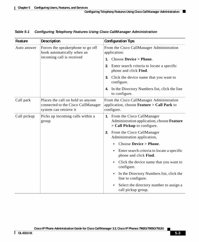
Chapter 5 Configuring Users, Features, and ServicesConfiguring Telephony Features Using Cisco CallManager Administration
Table 5-1 Configuring Telephony Features Using Cisco CallManager Administration
Feature Description Configuration Tips
Auto answer Forces the speakerphone to go off hook automatically when an incoming call is received
From the Cisco CallManager Administration application:
1. Choose Device > Phone.
2. Enter search criteria to locate a specific phone and click Find.
3. Click the device name that you want to configure.
4. In the Directory Numbers list, click the line to configure.
Call park Places the call on hold so anyone connected to the Cisco CallManager system can retrieve it
From the Cisco CallManager Administration application, choose Feature > Call Park to configure.
Call pickup Picks up incoming calls within a group
1. From the Cisco CallManager Administration application, choose Feature > Call Pickup to configure.
2. From the Cisco CallManager Administration application,
• Choose Device > Phone.
• Enter search criteria to locate a specific phone and click Find.
• Click the device name that you want to configure.
• In the Directory Numbers list, click the line to configure.
• Select the directory number to assign a call pickup group.
5-3Cisco IP Phone Administration Guide for Cisco CallManager 3.3, Cisco IP Phones 7902G/7905G/7912G
OL-6313-01
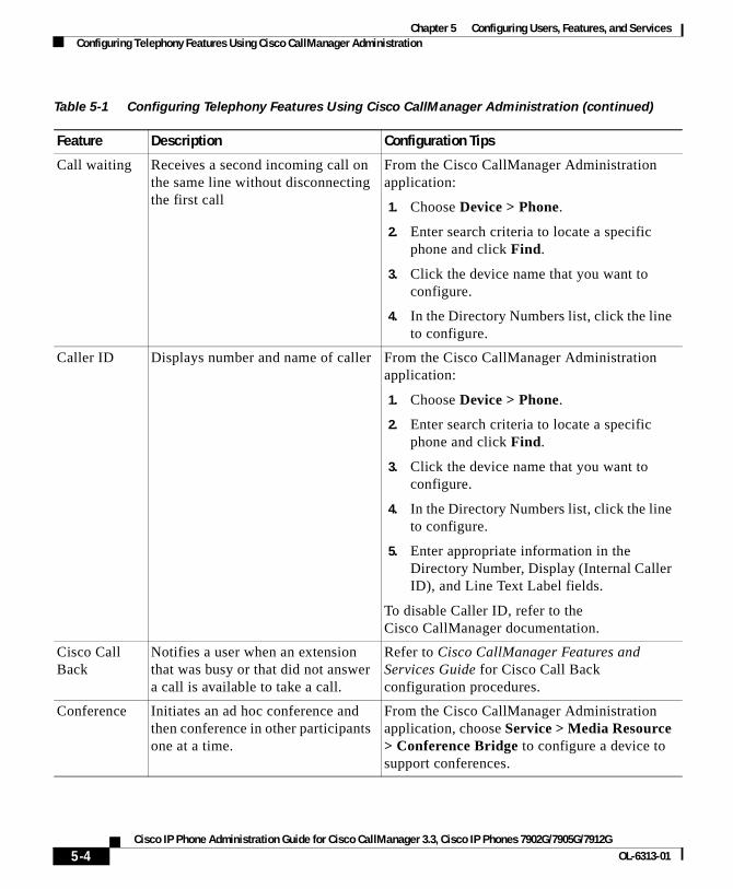
Chapter 5 Configuring Users, Features, and ServicesConfiguring Telephony Features Using Cisco CallManager Administration
Call waiting Receives a second incoming call on the same line without disconnecting the first call
From the Cisco CallManager Administration application:
1. Choose Device > Phone.
2. Enter search criteria to locate a specific phone and click Find.
3. Click the device name that you want to configure.
4. In the Directory Numbers list, click the line to configure.
Caller ID Displays number and name of caller From the Cisco CallManager Administration application:
1. Choose Device > Phone.
2. Enter search criteria to locate a specific phone and click Find.
3. Click the device name that you want to configure.
4. In the Directory Numbers list, click the line to configure.
5. Enter appropriate information in the Directory Number, Display (Internal Caller ID), and Line Text Label fields.
To disable Caller ID, refer to the Cisco CallManager documentation.
Cisco Call Back
Notifies a user when an extension that was busy or that did not answer a call is available to take a call.
Refer to Cisco CallManager Features and Services Guide for Cisco Call Back configuration procedures.
Conference Initiates an ad hoc conference and then conference in other participants one at a time.
From the Cisco CallManager Administration application, choose Service > Media Resource > Conference Bridge to configure a device to support conferences.
Table 5-1 Configuring Telephony Features Using Cisco CallManager Administration (continued)
Feature Description Configuration Tips
5-4Cisco IP Phone Administration Guide for Cisco CallManager 3.3, Cisco IP Phones 7902G/7905G/7912G
OL-6313-01

Chapter 5 Configuring Users, Features, and ServicesConfiguring Telephony Features Using Cisco CallManager Administration
Forward Forwards all calls to the designated directory number
From the Cisco CallManager Administration application:
1. Choose Device > Phone.
2. Enter search criteria to locate a specific phone and click Find.
3. Click the device name that you want to configure.
4. In the Directory Numbers list, click the line to configure.
You can configure Forward All, Forward Busy, or Forward No Answer.
Users can also designate the forward numbers from their Cisco IP Phone or from the User Options web pages.
Group call pickup
Allows users to pick up incoming calls within their own group or in other groups
1. From the Cisco CallManager Administration application, choose Feature > Call Pickup to configure.
2. From the Cisco CallManager Administration application,
• Choose Device > Phone.
• Enter search criteria to locate a specific phone and click Find.
• Click the device name that you want to configure.
• In the Directory Numbers list, click the line to configure.
• Select the directory number to assign a call pickup group.
Hold Places an active call on hold This feature requires no configuration, unless you want to use music on hold. See “Music-on-Hold” in this table for information.
Table 5-1 Configuring Telephony Features Using Cisco CallManager Administration (continued)
Feature Description Configuration Tips
5-5Cisco IP Phone Administration Guide for Cisco CallManager 3.3, Cisco IP Phones 7902G/7905G/7912G
OL-6313-01
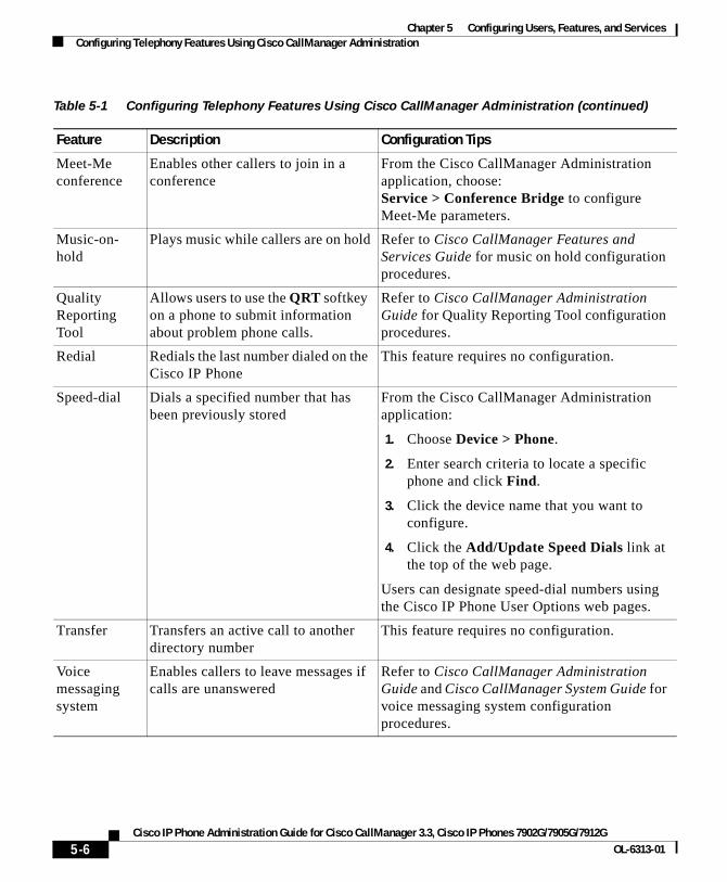
Chapter 5 Configuring Users, Features, and ServicesConfiguring Telephony Features Using Cisco CallManager Administration
Meet-Me conference
Enables other callers to join in a conference
From the Cisco CallManager Administration application, choose:Service > Conference Bridge to configure Meet-Me parameters.
Music-on- hold
Plays music while callers are on hold Refer to Cisco CallManager Features and Services Guide for music on hold configuration procedures.
Quality Reporting Tool
Allows users to use the QRT softkey on a phone to submit information about problem phone calls.
Refer to Cisco CallManager Administration Guide for Quality Reporting Tool configuration procedures.
Redial Redials the last number dialed on the Cisco IP Phone
This feature requires no configuration.
Speed-dial Dials a specified number that has been previously stored
From the Cisco CallManager Administration application:
1. Choose Device > Phone.
2. Enter search criteria to locate a specific phone and click Find.
3. Click the device name that you want to configure.
4. Click the Add/Update Speed Dials link at the top of the web page.
Users can designate speed-dial numbers using the Cisco IP Phone User Options web pages.
Transfer Transfers an active call to another directory number
This feature requires no configuration.
Voice messaging system
Enables callers to leave messages if calls are unanswered
Refer to Cisco CallManager Administration Guide and Cisco CallManager System Guide for voice messaging system configuration procedures.
Table 5-1 Configuring Telephony Features Using Cisco CallManager Administration (continued)
Feature Description Configuration Tips
5-6Cisco IP Phone Administration Guide for Cisco CallManager 3.3, Cisco IP Phones 7902G/7905G/7912G
OL-6313-01

Chapter 5 Configuring Users, Features, and ServicesAdding Users to Cisco CallManager
Adding Users to Cisco CallManagerThe Cisco CallManager Administration application allows you to display and maintain information about users on the network.
You must configure features to allow users to perform the following actions:
• Access the corporate directory and other customized directories from a Cisco IP Phone
• Create their own personal directories
• Set up their own speed dial and call forwarding numbers
To set up these features, you must first add users to Cisco CallManager, using either of the following methods:
• To add users individually, use the Cisco CallManager Administration application and select User >Add a New User.
Refer to Cisco CallManager Administration Guide, Cisco CallManager System Guide, or Cisco CallManager Administration online help in the application for details.
• To add users in batches, use the Bulk Administration Tool. This method also enables you to set an identical default password for all users.
Refer to Bulk Administration Tool User Guide for details.
Configuring the Corporate DirectoryFrom the Cisco IP Phone models 7905G/7912G, users can look up directory numbers for their co-workers. To support this feature, you must first configure corporate directories
Cisco CallManager uses a Lightweight Directory Access Protocol (LDAP) directory to store authentication and authorization information about users of Cisco CallManager applications, which interface with the Cisco CallManager. Authentication establishes the user right to access the system, while authorization identifies the telephony resources that a user is permitted to use, such as a specific telephone extension.
5-7Cisco IP Phone Administration Guide for Cisco CallManager 3.3, Cisco IP Phones 7902G/7905G/7912G
OL-6313-01
Chapter 5 Configuring Users, Features, and ServicesSetting Up Services
To install and set up these features, refer to Installing and Configuring the Cisco Customer Directory Configuration Plugin. This book guides you through the configuration process for integrating Cisco CallManager with Microsoft Active Directory and Netscape Directory Server.
After the LDAP directory configuration completes, users can use the Directories menu on the Cisco IP Phone models 7905G/ 7912G to look up users in the corporate directory.
Setting Up ServicesThe Menu button on the Cisco IP Phone gives users access to Cisco IP Phone services. These services comprise XML applications that enable the display of interactive content on the phone. Examples of services include local movie times, stock quotes, and weather reports.
Cisco CallManager provides sample Cisco IP Phone Services applications. You can also create customized applications for your site.
Note The Cisco IP Phone models 7905G/ 7912G do not support graphic-based XML applications. These phones support audio and text based XML applications only.
Before a user can access any service,
• You as the system administrator must use the Cisco CallManager Administration application to configure available services.
• The user must subscribe to services using the Cisco IP Phone User Options application. This web-based application provides a graphical user interface (GUI) for limited, end-user configuration of IP Phone applications.
Before you set up services, gather the URLs for the sites you want to set up and verify that users can access those sites from your corporate IP telephony network.
To set up these services, choose Feature > Cisco IP Phone Services from the Cisco CallManager Administration application. Refer to Cisco CallManager Administration Guide and Cisco CallManager System Guide for more information.
5-8Cisco IP Phone Administration Guide for Cisco CallManager 3.3, Cisco IP Phones 7902G/7905G/7912G
OL-6313-01
Chapter 5 Configuring Users, Features, and ServicesProviding Information to Users Via a Web Site
After you configure these services, verify that your users have access to the Cisco CallManager IP Phone Options web-based application, from which they can select and subscribe to configured services. See the “How Users Subscribe to Services and Configure Phone Features” section on page 5-10 for a summary of the information that you must provide to end users.
Providing Information to Users Via a Web SiteIf you are a system administrator, you are likely the primary source of information for Cisco IP Phone users in your network or company. It is important to provide current and thorough information to end users.
Cisco recommends that you create a web page on your internal support site that provides end users with important information about their new Cisco IP Phones.
Consider adding the following types of information to this site:
• How Users Obtain Support for the Cisco IP Phone, page 5-9
• How Users Get Copies of Cisco IP Phone Manuals, page 5-9
• How Users Configure Phone Features, page 5-11
• How Users Access Voice Messages, page 5-11
How Users Obtain Support for the Cisco IP PhoneOther documentation for your Cisco IP Phone may instruct users to direct some questions to a system administrator. To be able to successfully use some of the phone’s features (speed dial numbers, voice messaging system access), users must receive information from you or your network team or be able to contact you for assistance.
How Users Get Copies of Cisco IP Phone ManualsYou should provide end users with access to user documentation for the Cisco IP Phones. This documentation includes detailed user instructions for key phone features. See the “Related Documentation” section on page xiii for more information.
5-9Cisco IP Phone Administration Guide for Cisco CallManager 3.3, Cisco IP Phones 7902G/7905G/7912G
OL-6313-01
Chapter 5 Configuring Users, Features, and ServicesProviding Information to Users Via a Web Site
Because there are several Cisco IP Phone models available, users might have difficulty locating their specific documentation on the Cisco.com website. To assist users in finding their documentation, we recommend that you provide links to the current documentation. This ensures that users have access to the latest and most up-to-date documentation. However, if you do not want to or cannot send users to Cisco.com, we suggest that you download the PDF files and provide them to end users on your website.
• For a list of available documentation, go to the Cisco IP Phone website at: http://www.cisco.com/univercd/cc/td/doc/product/voice/c_ipphon/ip_clmgr/index.htm and select your preferred language.
• For more information about viewing or ordering documentation, see the “Obtaining Documentation” section on page xiv.
How Users Subscribe to Services and Configure Phone FeaturesEnd users can perform a variety of activities using the Cisco IP Phone User Options web page. These activities vary depending on the Cisco IP Phone model a user has, and can include subscribing to services, setting up speed dial and call forwarding numbers, configuring ring settings, and creating a personal address book. Keep in mind that being able to configure settings on a phone using a web site might be a new paradigm for your end users. You need to provide as much information as possible to ensure that they can successfully access and use the User Options.
Be sure to provide end users with the following information about the User Options page:
• The URL required to access the application.
http://serverName/CCMUser/, where serverName is the host on which the web server is installed.
• A user ID and default password needed to access the application.
These settings correspond to the values you entered when you added the user to Cisco CallManager (see the “Adding Users to Cisco CallManager” section on page 5-7).
• A brief description of what a web-based, graphic user interface application is, and how it is accessed with a Web browser.
• Outline the tasks that users can expect to accomplish with the application.
5-10Cisco IP Phone Administration Guide for Cisco CallManager 3.3, Cisco IP Phones 7902G/7905G/7912G
OL-6313-01

Chapter 5 Configuring Users, Features, and ServicesProviding Information to Users Via a Web Site
How Users Configure Phone FeaturesEnd users can perform a variety of activities using the Cisco IP Phone User Options web page. These activities vary depending on the Cisco IP Phone model a user has, and can include setting up speed dial and call forwarding numbers. Keep in mind that being able to configure settings on a phone using a web site might be a new paradigm for your end users. You need to provide as much information as possible to ensure that they can successfully access and use the User Options.
Be sure to provide end users with the following information about the User Options page:
• The URL required to access the application
http://serverName/CCMUser/, where serverName is the host on which the web server is installed.
• A user ID and default password needed to access the application
These settings correspond to the values you entered when you added the user to Cisco CallManager (see the“Adding Users to Cisco CallManager” section on page 5-7).
• A brief description of what a web-based, graphic user interface application is, and how it is accessed with a web browser.
• Outline the tasks that users can expect to accomplish with the application.
How Users Access Voice MessagesCisco CallManager provides you with the flexibility to integrate with many different voice messaging systems, including the Cisco Unity voice messaging system. However, because you can integrate with many different systems, you must provide users with information about how to use your specific system.
You should inform each user of the following information:
• How to access the voice messaging system account.
Make sure that you have used Cisco CallManager to configure the Messages button on the Cisco IP Phone.
5-11Cisco IP Phone Administration Guide for Cisco CallManager 3.3, Cisco IP Phones 7902G/7905G/7912G
OL-6313-01
Chapter 5 Configuring Users, Features, and ServicesProviding Information to Users Via a Web Site
• Initial password for accessing the voice messaging system.
Make sure that you have configured a default voice messaging system password for all users.
• How the phone indicates that messages are waiting.
Make sure that you have used Cisco CallManager to set up a message waiting indicator (MWI) method.
5-12Cisco IP Phone Administration Guide for Cisco CallManager 3.3, Cisco IP Phones 7902G/7905G/7912G
OL-6313-01
Cisco IP Phone Administration Guide for Cisco CallManager 3OL-6313-01
C H A P T E R 6
Troubleshooting the Cisco IP PhoneCisco IP Phones provide diagnostic information that can assist you with troubleshooting problems in your IP telephony network.
This chapter includes the following sections:
• Obtaining Status, Model, and Version Information, page 6-2
• Monitoring Cisco IP Phones Remotely, page 6-7
• Resetting the Cisco IP Phone, page 6-8
• Erasing the Local Configuration, page 6-8
• Updating the Firmware Version, page 6-10
• Checking the Light Indicators on a Cisco IP Phone 7902G, page 6-11
• Resolving Startup Problems, page 6-12
• Resolving Known Issues, page 6-21
• Resolving Known Issues, page 6-21
• Where to Go for More Information, page 6-23
Note You can collect information for troubleshooting and store this information in a log file. For more information, see the “Collecting Information for Troubleshooting” section on page A-30.
6-1.3, Cisco IP Phones 7902G/7905G/7912G
Chapter 6 Troubleshooting the Cisco IP PhoneObtaining Status, Model, and Version Information
Obtaining Status, Model, and Version InformationOn a Cisco IP Phone or from a phone’s web page, you can obtain status information about the current call and the network, and verify the phone model and installed firmware version.
This section covers these topics:
• Viewing Status Messages, page 6-2
• Displaying Network Statistics, page 6-3
• Verifying Model and Serial Number, page 6-5
• Verifying Firmware Version, page 6-6
Viewing Status MessagesUse the status messages to diagnose network configuration problems. You can access these messages at any point, even if the phone has not finished starting up.
Note This feature does not apply to the Cisco IP Phone 7902G.
Cisco IP Phone Models 7905G/7912G
Procedure
Step 1 Press the Menu button.
Step 2 Use the Navigation button to select Settings, and then press the Select softkey.
Step 3 Select Status, and then press the Select softkey.
Step 4 Select Status Messages, and then press the Select softkey.
The phone displays the name of the configuration file in the following format:
SEPDefault.cnf.xml or SEPmacaddress
6-2Cisco IP Phone Administration Guide for Cisco CallManager 3.3, Cisco IP Phones 7902G/7905G/7912G
OL-6313-01
Chapter 6 Troubleshooting the Cisco IP PhoneObtaining Status, Model, and Version Information
Related Topics
• Adding Phones Manually, page 2-14
• Configuring IP Settings, page 4-15
• Modifying DHCP Settings, page 4-9
• Verifying Firmware Version, page 6-6
• Configuring TFTP Options, page 4-28
Displaying Network StatisticsNetwork statistics provide information about the phone and network performance.
Cisco IP Phone 7902G
Procedure
Step 1 Open the Phone Configuration web page.
a. Open your web browser and enter the following URL, where IPaddress is the IP address of your phone
http://IPaddress
b. Press Enter.
The Phone Configuration web page appears.
Step 2 Click Network Statistics hyperlink.
The Network Statistics page shows the following information:
• Elapsed Time—amount of time that has elapsed since the phone connected to Cisco CallManager.
• Receive Packets—number of packets received at the phone.
• Transmit Packets—number of transmitted at the phone.
• Broadcast—number of broadcast packets received.
• Multicast—Number of multicast packets on the network during the elapsed time
• Receive errors—number of receive errors at the phone.
6-3Cisco IP Phone Administration Guide for Cisco CallManager 3.3, Cisco IP Phones 7902G/7905G/7912G
OL-6313-01
Chapter 6 Troubleshooting the Cisco IP PhoneObtaining Status, Model, and Version Information
• Transmit errors—number of transmit errors at the phone.
• Receive overflow—Number packet overflows that the phone has experienced during the elapsed time
Cisco IP Phone Models 7905G/7912G
Procedure
Step 1 Press the Menu button
Step 2 Use the Navigation button to select Settings.
Step 3 Press the Select softkey.
Step 4 Select Status.
Step 5 Press the Select softkey.
Step 6 Select Network Statistics.
Step 7 Press the Select softkey.
Step 8 Use the Navigation button to display the available information:
• Rcv—number of packets received at the phone.
• Xmt—number of packets transmitted from the phone.
• REr—number of receive errors at the phone.
• Bcast—number of broadcast packets received.
• Elapsed Time—amount of time that has elapsed since the phone connected to Cisco CallManager.
6-4Cisco IP Phone Administration Guide for Cisco CallManager 3.3, Cisco IP Phones 7902G/7905G/7912G
OL-6313-01
Chapter 6 Troubleshooting the Cisco IP PhoneObtaining Status, Model, and Version Information
Verifying Model and Serial NumberYou can verify the model and serial number of Cisco IP Phones.
Cisco IP Phone 7902G
Procedure
Step 1 Open the Phone Configuration web page.
a. Open your web browser and enter the following URL, where IPaddress is the IP address of your phone
http://IPaddress
b. Press Enter.
The Phone Configuration web page appears.
Step 2 In the pane on the left, click Device Information.
The Device Information page displays the Product ID (model number) and serial number of the phone.
Cisco IP Phone Models 7905G/7912G
Procedure
Step 1 Press the Menu button.
Step 2 Use the Navigation button to select Settings.
Step 3 Press the Select softkey.
Step 4 Select Model Information.
Step 5 Press the Select softkey.
Step 6 Use the Navigation button to display the following information:
• Model Number
• MAC Address
• AppLoadID—Identifier of the firmware running on the phone
6-5Cisco IP Phone Administration Guide for Cisco CallManager 3.3, Cisco IP Phones 7902G/7905G/7912G
OL-6313-01
Chapter 6 Troubleshooting the Cisco IP PhoneObtaining Status, Model, and Version Information
• BootLoadID—Identifier of the factory-installed load running on the phone
• Serial Number
Verifying Firmware VersionYou can verify the firmware version for Cisco IP Phones.
Cisco IP Phone 7902G
Procedure
Step 1 Open the Phone Configuration web page.
a. Open your web browser and enter the following URL, where IPaddress is the IP address of your phone
http://IPaddress
b. Press Enter.
The Phone Configuration web page appears.
Step 2 In the pane on the left, click Device Information.
The Device Information page displays the following information:
• App Load ID—Identifier of the firmware running on the phone
• Boot Load ID—Identifier of the factory-installed load running on the phone
Cisco IP Phone Models 7905G/7912G
Procedure
Step 1 Press the Menu button.
Step 2 Use the Navigation button to select Settings, and then press the Select softkey.
6-6Cisco IP Phone Administration Guide for Cisco CallManager 3.3, Cisco IP Phones 7902G/7905G/7912G
OL-6313-01
Chapter 6 Troubleshooting the Cisco IP PhoneMonitoring Cisco IP Phones Remotely
Step 3 Select Status, and then press the Select softkey.
Step 4 Select Firmware Versions, and then press the Select softkey.
The following information appears:
• App Load ID
• Boot Load ID
• Version
Monitoring Cisco IP Phones RemotelyYou can remotely monitor the network activity of any Cisco IP Phone on your network using a web browser. To do so, open a web browser and enter the following URL, where IPaddress is the currently assigned IP address of the phone:
http://IPaddress
To confirm the IP address, you can either
• search for a particular phone in Cisco CallManager by choosing Device > Phone. Phones registered with Cisco CallManager display the IP address at the top of the Phone Configuration page.
• obtain the IP address from the phone itself by choosing Settings > Network Configuration > IP Address.
When you enter the IP address of a Cisco IP Phone into a web browser, the following information appears:
• Device information
• Network information
• Network statistics
• Device logs
The web page also lets you view and change a variety of configuration parameters. For more information about these parameters and how to change them, see Appendix A, “Additional Configuration Methods, Parameters, and Procedures.”
6-7Cisco IP Phone Administration Guide for Cisco CallManager 3.3, Cisco IP Phones 7902G/7905G/7912G
OL-6313-01
Chapter 6 Troubleshooting the Cisco IP PhoneResetting the Cisco IP Phone
Resetting the Cisco IP Phone If you reset the phone, any changes made that have not been saved are lost and set back to default settings.
Cisco IP Phone 7902G
Procedure
• Press **#** to reset the Cisco IP Phone 7902G.
The phone cycles through normal startup procedures.
Cisco IP Phone Models 7905G/7912G
Procedure
Step 1 Press **#** to reset the Cisco IP Phone.
The phone displays “Do you want to reboot the phone?”
Step 2 Press the Yes softkey.
The phone cycles through normal startup procedures.
Erasing the Local ConfigurationIf you want to erase all locally stored configuration options, you can erase the configuration and restore settings to their default values, including enabling DHCP.
Caution Erasing the local configuration removes all user-defined changes, except ringer sound, made locally on the Cisco IP Phone. If you choose this option, these settings are set back to their default values.
6-8Cisco IP Phone Administration Guide for Cisco CallManager 3.3, Cisco IP Phones 7902G/7905G/7912G
OL-6313-01

Chapter 6 Troubleshooting the Cisco IP PhoneErasing the Local Configuration
Cisco IP Phone 7902G
Procedure
Step 1 Lift the handset, then press and hold the Menu button for about 3 seconds.
Step 2 Press # to go to the extended menu.
Step 3 Enter the code # 322873738.
Step 4 Hang up the phone. The phone resets.
Cisco IP Phone Models 7905G/7912G
Procedure
Step 1 Press the Menu button.
Step 2 Use the Navigation button to select Settings, and then press the Select softkey.
Step 3 Use the Navigation button to select Network Configuration, and then press the Select softkey.
Step 4 Perform either of these procedures:
• Procedure A:
– Press **2. The phone displays “Do you want to reset all system settings to default values?”
– Press the Yes softkey.
• Procedure B:
– Press **#. If your phone displays “Enter Admin Password,” enter your password and then press the Enter softkey. Make sure that an unlocked padlock icon appears in the upper-right corner of your LCD.
– Scroll to Erase Configuration.
– Press the Yes softkey and then press the Save softkey.
The phone cycles through normal startup procedures.
6-9Cisco IP Phone Administration Guide for Cisco CallManager 3.3, Cisco IP Phones 7902G/7905G/7912G
OL-6313-01
Chapter 6 Troubleshooting the Cisco IP PhoneUpdating the Firmware Version
Updating the Firmware VersionYou can update the firmware version using the Cisco CallManager Administration application. You can also update the firmware version using a profile file. See Appendix A, “Additional Configuration Methods, Parameters, and Procedures” for information about profile files.
Before You Begin
Read the “Read Me” files included with Cisco software updates. These files provide important updated information about installing and configuring the new software.
Procedure
Step 1 Obtain an updated phone load.
You can download the latest available software from the Cisco Service & Support Software Center:http://www.cisco.com/kobayashi/sw-center/sw-voice.shtml
Step 2 Install the update.
Step 3 From the Cisco CallManager Administration choose System > Device Defaults.
Locate the Device Type field corresponding to the model IP Phone.
Step 4 Enter the new device load in the Load Information field.
You can typically locate this information in the Read Me file distributed with the software update. The Read Me file for the Cisco IP Phone models 7905G/7912G begins with LD
Step 5 Click Update.
Step 6 From Cisco CallManager Administration, choose System > CallManager Group.
6-10Cisco IP Phone Administration Guide for Cisco CallManager 3.3, Cisco IP Phones 7902G/7905G/7912G
OL-6313-01
Chapter 6 Troubleshooting the Cisco IP PhoneChecking the Light Indicators on a Cisco IP Phone 7902G
Step 7 From the Cisco CallManager Group list, choose the group you want to update.
Step 8 Click Reset Devices.
Related Topic
• Verifying Firmware Version, page 6-6
Checking the Light Indicators on a Cisco IP Phone 7902G
Refer to the following table for explanations about the light indicators on a Cisco IP Phone 7902G.
Problem Explanation
After the phone is connected to power, the phone Hold and Menu buttons blink red and green respectively.
There is no Ethernet link. See the “Connecting the Cisco IP Phone to the Network” section on page 3-4 and the “Symptom: Cisco IP Phone Does Not Start Up” section on page 6-12.
After the phone is connected to power, the phone Menu button blinks green about every two seconds.
The VLAN is not set up. See the “Modifying DHCP Settings” section on page 4-9.
After the phone is connected to power, the phone Menu button blinks twice about every two seconds.
The IP address is not set up. See the “Assigning an IP Address” section on page 4-15.
After the phone is connected to power, the phone Menu button blinks three times about every two seconds.
The Cisco CallManager is not set up. See the “Adding Phones to the Cisco CallManager Database” section on page 2-12.
After the phone is connected to power, the phone Hold button is steady red and the Menu button is steady green.
The phone is not registered. See the “Symptom: Cisco IP Phone Not Registering with Cisco CallManager” section on page 6-13.
6-11Cisco IP Phone Administration Guide for Cisco CallManager 3.3, Cisco IP Phones 7902G/7905G/7912G
OL-6313-01
Chapter 6 Troubleshooting the Cisco IP PhoneResolving Startup Problems
Resolving Startup ProblemsAfter installing a Cisco IP Phone into your network and adding it to Cisco CallManager, the phone should start up as described in the “Verifying the Phone Startup Process” section on page 3-9. If the phone does not start up properly, these sections can help you resolve the problem:
• Symptom: Cisco IP Phone Does Not Start Up, page 6-12
• Symptom: Cisco IP Phone Not Registering with Cisco CallManager, page 6-13
• Symptom: Cisco IP Phone Resetting, page 6-18
Note Any procedures that refer to an LCD screen display problem apply only to the Cisco IP Phone models 7905G/7912G.
Symptom: Cisco IP Phone Does Not Start UpIf you connect a Cisco IP Phone into the network port, the LEDs should light up and, on the Cisco IP Phone models 7905G/7912G, messages should appear on the LCD display. (See the “Verifying the Phone Startup Process” section on page 3-9 for information on the normal startup process.) If the phone does not proceed through this normal startup process, you must determine if the phone is functional or if anything else in the configuration is causing the phone to not start up properly.
After the phone is connected to power, the phone handset indicator light is steady red and the Menu button is steady green.
The phone has a duplicate IP address. See the “Assigning an IP Address” section on page 4-15.
The phone Hold button flashes red and the Menu button flashes green at the same time.
The phone’s firmware is being upgraded. After the upgrade, all LEDs on the phone should be off.
Problem Explanation
6-12Cisco IP Phone Administration Guide for Cisco CallManager 3.3, Cisco IP Phones 7902G/7905G/7912G
OL-6313-01
Chapter 6 Troubleshooting the Cisco IP PhoneResolving Startup Problems
To determine whether the phone is functional, you must eliminate any other potential problems, such as faulty cables, network outages, lack of power, and so on. Follow these suggestions to systematically eliminate these other causes.
Procedure
Step 1 To verify that the network port is functional:
a. Exchange the Ethernet cables with cables you know are functional.
b. Disconnect a functioning Cisco IP Phone from another port and connect it to this network port to verify the port is active.
c. Connect the Cisco IP Phone that will not start up to a different network port that you know to be good.
d. Connect the Cisco IP Phone that will not start up directly to the port on the switch, eliminating the patch panel connection in the office.
Step 2 To verify that the phone is receiving power:
a. Verify that the electrical outlet is functional.
b. If you are using in-line power, use the external power supply instead.
c. If you are using the external power supply, switch with a unit you know to be functional.
Step 3 Cisco IP Phone models 7905G/7912G only. If, after attempting these solutions, the LCD screen persists in not displaying any characters for at least five minutes, contact a Cisco technical support representative for additional assistance.
Symptom: Cisco IP Phone Not Registering with Cisco CallManager
If a phone proceeds past the first stage (LED buttons flashing on and off), and, on a Cisco IP Phone model 7905G/7912G, continues to cycle through the messages displaying on the LCD screen, then the phone is not starting up properly. The phone cannot successfully start up unless it is connected to the Ethernet network and it has registered with a Cisco CallManager server.
6-13Cisco IP Phone Administration Guide for Cisco CallManager 3.3, Cisco IP Phones 7902G/7905G/7912G
OL-6313-01
Chapter 6 Troubleshooting the Cisco IP PhoneResolving Startup Problems
These sections can assist you in determining the reason the phone is unable to start up properly:
• Registering the Phone with Cisco CallManager, page 6-14
• Checking Network Connectivity, page 6-14
• Verifying TFTP Server Settings, page 6-15
• Verifying IP Addressing and Routing, page 6-15
• Verifying DNS Settings, page 6-16
• Verifying Cisco CallManager Settings, page 6-16
• Cisco CallManager and TFTP Services Are Not Running, page 6-16
• Creating a New Configuration File, page 6-17
Registering the Phone with Cisco CallManager
Registration with a Cisco CallManager server can only be successful if the phone has been added to the server or if auto-registration is enabled. Review the information and procedures in the “Adding Phones to the Cisco CallManager Database” section on page 2-12 to ensure that the phone has been added to the Cisco CallManager database.
To verify that the phone is in the Cisco CallManager database, use Device > Find from Cisco CallManager to search for the phone based on its MAC Address. Verify the MAC address to search for by pressing Settings > Network Configuration > MAC address on the phone.
If the phone is already in the Cisco CallManager database, its configuration file might be damaged. See the “Creating a New Configuration File” section on page 6-17 for assistance.
Checking Network Connectivity
If the network is down between the phone and the TFTP server or Cisco CallManager, the phone cannot start up properly. Ensure that the network is currently up and running.
6-14Cisco IP Phone Administration Guide for Cisco CallManager 3.3, Cisco IP Phones 7902G/7905G/7912G
OL-6313-01

Chapter 6 Troubleshooting the Cisco IP PhoneResolving Startup Problems
Verifying TFTP Server Settings
The Cisco IP Phone uses the TFTP server setting (Settings > Network Configuration > TFTP Server 1) to identify the Cisco CallManager server. If this setting is incorrect, the Cisco IP Phone might continually cycle while attempting to contact the identified TFTP Server.
If you have assigned a static IP address to the phone, you must manually enter this setting. See the “Configuring IP Settings” section on page 4-15.
If you are using DHCP, the phone obtains the address for the TFTP server from the DHCP server. Check the IP address configured in Option 150. Refer to Configuring Windows 2000 DHCP Server for Cisco Call Manager on Cisco.com: http://www.cisco.com/warp/customer/788/AVVID/win2000_dhcp.html
You can also enable the phone to use an alternate TFTP server (Settings > Network Configuration > Alternate TFTP Server). This is particularly useful if this phone was recently moved from a different location, such as a test lab to a production network.
You must unlock the network settings before you can assign an alternate TFTP server (see “Accessing Network Configuration Settings from a Cisco IP Phone” section on page 4-2).
Verifying IP Addressing and Routing
You should verify the IP addressing and routing settings on the IP Phone. If you are using DHCP, the DHCP server should provide these values. If you have assigned a static IP address to the phone, you must enter these values manually.
On the Cisco IP Phone, press Settings > Network Configuration and check for the following problems:
• DHCP Server—has no address
If you have assigned a static IP address to the phone, you do not need to enter a value here. However, if you are using a DHCP server, this field must have a value. If it does not, check your IP routing and VLAN configuration. Refer to Troubleshooting Switch Port Problems on Cisco.com: http://www.cisco.com/warp/customer/473/53.shtml
• IP address, subnet mask, or default router—have no addresses
If you have assigned a static IP address to the phone, you must manually enter these settings. See the “Configuring IP Settings” section on page 4-15.
6-15Cisco IP Phone Administration Guide for Cisco CallManager 3.3, Cisco IP Phones 7902G/7905G/7912G
OL-6313-01
Chapter 6 Troubleshooting the Cisco IP PhoneResolving Startup Problems
If you are using DHCP, check the IP addresses distributed by your DHCP server. Refer to Understanding and Troubleshooting DHCP in Catalyst Switch or Enterprise Networks on Cisco.com: http://www.cisco.com/warp/customer/473/100.html#41
Verifying DNS Settings
If you are using DNS to refer to the TFTP server or Cisco CallManager, you must ensure you have specified a DNS server (Settings > Network Configuration > DNS Server 1). You should also verify that you have a CNAME entry in the DNS server for the TFTP server and Cisco CallManager system.
You must also ensure that DNS is configured to do reverse look-ups. The default setting on Windows 2000 is to perform forward-only look-ups.
Verifying Cisco CallManager Settings
On the Cisco IP Phone, press Settings > Network Configuration > CallManager 1, 2, 3, 4. The Cisco IP Phone attempts to open a TCP connection to all the Cisco CallManager servers that are part of the assigned Cisco CallManager group. If none of these fields have IP addresses or state “Active” or “Standby”, the phone is not properly registered with Cisco CallManager. See the “Registering the Phone with Cisco CallManager” section on page 6-14 for tips on resolving this problem.
Cisco CallManager and TFTP Services Are Not Running
If the Cisco CallManager or TFTP services are not running, phones might not be able to start up properly. However, in this case, it is likely that you are experiencing a system-wide failure. Rather than being isolated to one phone that is experiencing problems, in this situation many or all phones and other devices are not able to start up properly.
If the Cisco CallManager service is not running, all devices on the network that rely on it to make phone calls will be affected. If the TFTP service is not running, many devices will not be able to start up successfully.
6-16Cisco IP Phone Administration Guide for Cisco CallManager 3.3, Cisco IP Phones 7902G/7905G/7912G
OL-6313-01
Chapter 6 Troubleshooting the Cisco IP PhoneResolving Startup Problems
Procedure
Step 1 From the Cisco CallManager Administration window, choose Application > Cisco CallManager Serviceability.
Step 2 Choose Tools > Control Center.
Step 3 From the Servers column, choose the primary Cisco CallManager server.
The window displays the service names for the server that you chose, the status of the services, and a service control panel to stop or start a service.
Step 4 If a service has stopped, click the Start button.
The Service Status symbol changes from a square to an arrow.
Creating a New Configuration File
If you continue to have problems with a particular phone, despite all attempts at resolution, the configuration file might be corrupted. You can manually create a new configuration file by following this procedure:
Procedure
Step 1 From Cisco CallManager, select Device > Phone > Find to locate the phone experiencing problems.
Step 2 Choose Delete to remove the phone from the Cisco CallManager database.
Step 3 In Cisco CallManager, choose Service > Cisco TFTP > Advanced and make sure that False appears in the Enable Caching of Configuration Files in the Cisco TFTP Configuration page.
Step 4 Search the hard drive of the Cisco CallManager server for files named SEP*.cnf.xml. This file should be in a folder containing the configuration files for all the registered phones.
Step 5 Make a copy of a configuration file for a functional phone of the same type as the problematic phone. For example, if the phone experiencing problems is a Cisco IP Phone 7905G, make a copy of a configuration file for another phone of this model.
6-17Cisco IP Phone Administration Guide for Cisco CallManager 3.3, Cisco IP Phones 7902G/7905G/7912G
OL-6313-01
Chapter 6 Troubleshooting the Cisco IP PhoneResolving Startup Problems
Step 6 Rename this to match the name of the configuration file for the problematic phone.
Use the convention SEP<MAC address>.cnf.xml, where <MAC address> is the MAC address for the deleted phone.
Step 7 Replace the old configuration file with the new one you created.
Step 8 Add the phone to Cisco CallManager database. See the “Adding Phones Manually” section on page 2-14 for details.
Step 9 Power cycle the phone.
Symptom: Cisco IP Phone ResettingOnce a Cisco IP Phone has properly started up and registered with Cisco CallManager, you can reset it, forcing it to go through the startup process. At times, you might want to intentionally do this. For example, if you want to force a firmware upgrade from Cisco CallManager on to the phone. Anytime a phone has to load a new image, it has to restart itself and re-register with Cisco CallManager using the new image
However, if users report that their phones appear to be resetting during calls or while idle on their desk, you should investigate the cause. If the network connection and Cisco CallManager connection are stable, the Cisco IP Phone should not reset on its own.
Typically, the cause of the phones resetting can be categorized by problems connecting to the Ethernet network or to Cisco CallManager. These sections can help you identify the cause in your network:
• Verifying Physical Connection, page 6-19
• Identifying Intermittent Network Outages, page 6-19
• Verifying DHCP Settings, page 6-19
• Checking Static IP Address Settings, page 6-19
• Verifying Voice VLAN Configuration, page 6-20
• Verifying that the Phones Have Not Been Intentionally Reset, page 6-20
• Eliminating DNS or Other Connectivity Errors, page 6-20
6-18Cisco IP Phone Administration Guide for Cisco CallManager 3.3, Cisco IP Phones 7902G/7905G/7912G
OL-6313-01
Chapter 6 Troubleshooting the Cisco IP PhoneResolving Startup Problems
Verifying Physical Connection
Verify that the Ethernet connection to which the Cisco IP Phone is connected is up-and-running. For example, check if the particular port or switch to which the phone is connected is down.
Identifying Intermittent Network Outages
Intermittent network outages affect data and voice traffic differently. Your network might have been experiencing intermittent outages without detection, but data traffic can resend lost packets and verify packets are received and transmitted.
However, voice traffic cannot recapture lost packets. Rather than retransmitting a lost network connection, the phone resets and attempts to reconnect its network connection.
Therefore, if you are experiencing problems with the voice network, you should investigate whether an existing problem is simply being exposed at this point.
Verifying DHCP Settings
The following procedure can help you determine if the phone has been properly configured to use DHCP:
Procedure
Step 1 Verify that you have properly configured the phone to use DHCP. See the “Modifying DHCP Settings” section on page 4-9 for details.
Step 2 Verify that the DHCP server has been set up properly.
Step 3 Verify the DHCP lease duration. Cisco recommends that you set it to 8 days.
Checking Static IP Address Settings
If the phone has been assigned a static IP address, verify that you have entered the correct settings. See the “Configuring IP Settings” section on page 4-15.
6-19Cisco IP Phone Administration Guide for Cisco CallManager 3.3, Cisco IP Phones 7902G/7905G/7912G
OL-6313-01
Chapter 6 Troubleshooting the Cisco IP PhoneResolving Startup Problems
Verifying Voice VLAN Configuration
If the Cisco IP Phone appears to reset during heavy network usage (for example, following extensive web surfing on a computer connected to same switch as phone), it is likely that you do not have a voice VLAN configured.
Isolating the phones on a separate, auxiliary VLAN increases the quality of the voice traffic. See “Understanding How the Cisco IP Phone Interacts with the Cisco Catalyst Family of Switches” section on page 2-3 for more details.
Verifying that the Phones Have Not Been Intentionally Reset
If you are not the only administrator with access to Cisco CallManager, you should verify that no one else has intentionally reset the phones.
Eliminating DNS or Other Connectivity Errors
If the phone continues to reset, follow this procedure.
Procedure
Step 1 Reset the phone to factory defaults. See the “Resetting the Cisco IP Phone” section on page 6-8 for details.
Step 2 Modify DHCP and IP settings.
a. Disable DHCP. See the “Modifying DHCP Settings” section on page 4-9 for details.
b. Assign static IP values to the phone. See the “Configuring IP Settings” section on page 4-15 for details. Use the same default router setting used for other functioning Cisco IP Phones.
c. Assign TFTP server. See the “Configuring TFTP Options” section on page 4-28 for details. Use the same TFTP server used for other functioning Cisco IP Phones.
Step 3 On the Cisco CallManager server, verify that the local host files have the correct Cisco CallManager server name mapped to the correct IP address. Refer to Configuring The IP Hosts File on a Windows 2000 CallManager Server on Cisco.com: http://www.cisco.com/warp/customer/788/AVVID/cm_hosts_file.html
6-20Cisco IP Phone Administration Guide for Cisco CallManager 3.3, Cisco IP Phones 7902G/7905G/7912G
OL-6313-01
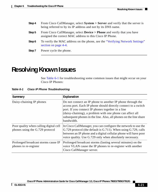
Chapter 6 Troubleshooting the Cisco IP PhoneResolving Known Issues
Step 4 From Cisco CallManager, select System > Server and verify that the server is being referred to by its IP address and not by its DNS name.
Step 5 From Cisco CallManager, select Device > Phone and verify that you have assigned the correct MAC address to this Cisco IP Phone.
Step 6 To verify the MAC address on the phone, see the “Verifying Network Settings” section on page 4-4.
Step 7 Power cycle the phone.
Resolving Known IssuesSee Table 6-1 for troubleshooting some common issues that might occur on your Cisco IP Phones:
Table 6-1 Cisco IP Phone Troubleshooting
Summary Explanation
Daisy-chaining IP phones Do not connect an IP phone to another IP phone through the access port. Each IP phone should directly connect to a switch port. If you connect IP phones together in a line (daisy-chaining), a problem with one phone can affect all subsequent phones in the line. Also, all phones on the line share bandwidth.
Poor quality when calling digital cell phones using the G.729 protocol
In Cisco CallManager, you can configure the network to use the G.729 protocol (the default is G.711). When using G.729, calls between an IP phone and a digital cellular phone will have poor voice quality. Use G.729 only when absolutely necessary.
Prolonged broadcast storms cause IP phones to re-register
Prolonged broadcast storms (lasting several minutes) on the voice VLAN cause the IP phones to re-register with another Cisco CallManager server.
6-21Cisco IP Phone Administration Guide for Cisco CallManager 3.3, Cisco IP Phones 7902G/7905G/7912G
OL-6313-01
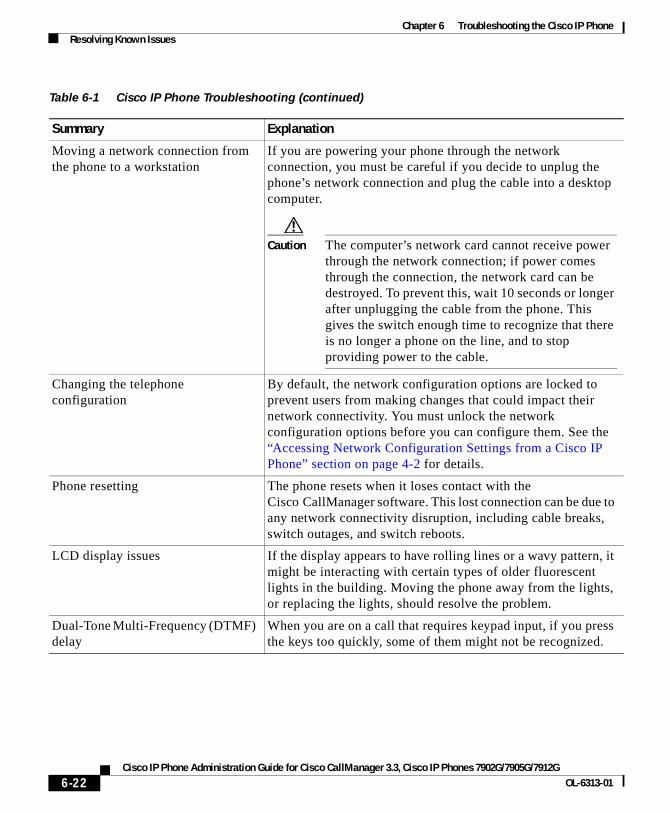
Chapter 6 Troubleshooting the Cisco IP PhoneResolving Known Issues
Moving a network connection from the phone to a workstation
If you are powering your phone through the network connection, you must be careful if you decide to unplug the phone’s network connection and plug the cable into a desktop computer.
Caution The computer’s network card cannot receive power through the network connection; if power comes through the connection, the network card can be destroyed. To prevent this, wait 10 seconds or longer after unplugging the cable from the phone. This gives the switch enough time to recognize that there is no longer a phone on the line, and to stop providing power to the cable.
Changing the telephone configuration
By default, the network configuration options are locked to prevent users from making changes that could impact their network connectivity. You must unlock the network configuration options before you can configure them. See the “Accessing Network Configuration Settings from a Cisco IP Phone” section on page 4-2 for details.
Phone resetting The phone resets when it loses contact with the Cisco CallManager software. This lost connection can be due to any network connectivity disruption, including cable breaks, switch outages, and switch reboots.
LCD display issues If the display appears to have rolling lines or a wavy pattern, it might be interacting with certain types of older fluorescent lights in the building. Moving the phone away from the lights, or replacing the lights, should resolve the problem.
Dual-Tone Multi-Frequency (DTMF) delay
When you are on a call that requires keypad input, if you press the keys too quickly, some of them might not be recognized.
Table 6-1 Cisco IP Phone Troubleshooting (continued)
Summary Explanation
6-22Cisco IP Phone Administration Guide for Cisco CallManager 3.3, Cisco IP Phones 7902G/7905G/7912G
OL-6313-01
Chapter 6 Troubleshooting the Cisco IP PhoneWhere to Go for More Information
Where to Go for More InformationIf you have additional questions about troubleshooting the Cisco IP Phones, several Cisco.com web sites can provide you with more tips. Choose from the sites available for your access level:
General Access
• Cisco IP Phone Troubleshooting Resources: http://www.cisco.com/pcgi-bin/Support/PSP/psp_view.pl?p=Hardware:IP_Phones&s=Troubleshooting
• Cisco IP Phone for Cisco CallManager documentation: http://www.cisco.com/univercd/cc/td/doc/product/voice/c_ipphon/ip_clmgr/index.htm
• Cisco Products and Technologies (Cisco Voice Applications, including Cisco CallManager): http://www.cisco.com/warp/public/44/jump/voice_applications.shtml
• Cisco Products and Technologies (Telephony, including Cisco IP Phones): http://www.cisco.com/warp/public/44/jump/telephony.shtml
Registered Cisco.com Users
• Technical Tips for Cisco CallManager, Attendant Applications, Utilities, and Technologies (includes Cisco IP Phones): http://www.cisco.com/warp/customer/788/AVVID/ccmaaut.shtml
• Top Issues for Voice, Telephony, and Messaging: http://www.cisco.com/warp/customer/788/top_issues/vox/vox_top_issues.shtml
• Cisco Technologies: http://www.cisco.com/cgi-bin/Support/PSP/index.pl?i=Technologies
• Cisco Products: http://www.cisco.com/cgi-bin/Support/PSP/index.pl?i=Products
• Voice, Telephony, and Messaging Solutions: http://www.cisco.com/warp/customer/788/AVVID/avvid_index.shtml
6-23Cisco IP Phone Administration Guide for Cisco CallManager 3.3, Cisco IP Phones 7902G/7905G/7912G
OL-6313-01

Chapter 6 Troubleshooting the Cisco IP PhoneWhere to Go for More Information
6-24Cisco IP Phone Administration Guide for Cisco CallManager 3.3, Cisco IP Phones 7902G/7905G/7912G
OL-6313-01
Cisco IP Phone Administration Guide for Cisco CallManager 3OL-6313-01
A
P P E N D I X A Additional Configuration Methods, Parameters, and ProceduresThe Cisco IP Phone must be correctly configured before it will operate properly. When you configure a phone, you specify parameters and values that instruct the phone how to operate in your environment. Configuring provides the phone with instructions for many aspects of its operation, including how to interact with the network and how to handle IP telephony protocols.
In general, configuring the Cisco IP Phone models 7902G/7905G/7912G can be accomplished through Cisco CallManager and through the network configuration options on a phone. These processes are described in detail in this manual.
This appendix describes the following additional methods for configuring the Cisco IP Phone models 7902G/7905G/7912G. These methods are optional and are available to help you configure your phones most efficiently and to provide certain configuration options that are not available through other methods.
• Through a profile file—A profile file contains various parameters and values for phone and network settings. This file is stored on a Trivial File Transfer Protocol (TFTP) server and is downloaded to the phone.
• Through the phone’s web page—Each phone has a web page from which you can view and update many parameter values.
• Through the phone’s Interactive Voice Response (IVR) system (Cisco IP Phone 7902G only)
This section covers the following topics:
• TFTP Configuring, page A-2
• Web Page Configuring, page A-6
A-1.3, Cisco IP Phones 7902G/7905G/7912G
Appendix A Additional Configuration Methods, Parameters, and ProceduresTFTP Configuring
• Configuration Parameters, page A-11
• Specifying Firmware Upgrade Instructions for the Cisco IP Phone, page A-21
• Using the Interactive Voice Response (IVR) System on the Cisco IP Phone 7902G, page A-22
• Changing the Logo on the Cisco IP Phone LCD Screen, page A-27
• Collecting Information for Troubleshooting, page A-30
TFTP ConfiguringYou can configure many parameters on the Cisco IP Phone models 7902G/7905G/7912G using a profile file stored on the TFTP server. A profile file is a binary file that contains a list of tag, length, and value triplets (TLVs) that represent some of the configuration parameters for the Cisco IP Phone. You can edit a text version of a profile file and then convert it to a binary file for the phone to download.
TFTP configuring works as follows:
1. The Cisco IP Phone 7902G will try to download from the TFTP server the profile file ffxxxxxxxxxxxx. The Cisco IP Phone model 7905G will try to download from the TFTP server the profile file ldxxxxxxxxxxxx. The Cisco IP Phone model 7912G will try to download from the TFTP server the profile file gkxxxxxxxxxxxx. In these file names, each xx is the two-digit lowercase hexadecimal representation of each integer in the phone’s MAC address.
2. If the ffxxxxxxxxxxxx, ldxxxxxxxxxxxx, or gkxxxxxxxxxxxx profile file does not exist, the Cisco IP Phone 7902G will try to download the profile file ffdefault.cfg, the Cisco IP Phone 7905G will try to download profile file lddefault.cfg, and the Cisco IP Phone 7912G will try to download profile file gkdefault.cfg
The ffxxxxxxxxxxxx, ldxxxxxxxxxxxx, or gkxxxxxxxxxxxx profile file can be used to configure a particular Cisco IP Phone. The ffdefault.cfg, lddefault.cfg, or gkdefault.cfg profile file can be used to simultaneously configure multiple phones of the same model with the same information.
A-2Cisco IP Phone Administration Guide for Cisco CallManager 3.3, Cisco IP Phones 7902G/7905G/7912G
OL-6313-01
Appendix A Additional Configuration Methods, Parameters, and ProceduresTFTP Configuring
Related Topics
• About Profile Files, page A-3
• Creating or Updating a Profile File, page A-4
• Configuration Parameters, page A-11
About Profile FilesThe TFTP server stores the common profile file lddefault.cfg and each phone-specific profile file in binary format. The Cisco IP Phone 7902G profile file name is ffxxxxxxxxxxxx, where each xx is the two-digit lowercase hexadecimal representation of each integer in the phone’s MAC address. The Cisco IP Phone models 7905G/7912G profile file name is ldxxxxxxxxxxxx, where each xx is the two-digit lowercase hexadecimal representation of each integer in the phone’s MAC address. The file name must be exactly 14 characters. For example, if the MAC address is 0.1.45.2.10.20, the file name is ld00012d020a14.
Note Profile file names begin with “ld,” which is a lowercase “L” followed by a lowercase “D.”
You can edit a profile file in text format on the TFTP server and then convert it to the binary format required by the phone. See the “Creating or Updating a Profile File” section on page A-4 for more information.
Configuration parameters are entered in the format “Parameter:value.” For example, the following entry specifies that the password for accessing a phone’s web page or Network Configuration screen is 12345: UIPassword:12345. See the “Configuration Parameters” section on page A-11 for more information about parameters and values.
Use the file example_uprofile.txt as a template for creating the text version of your Cisco IP Phone profile files. You can obtain the latest version of this file from the CCO website. It is included with the SCCP Software Package Zip file.
Note A profile file for your phone may contain some parameters that are not described in this manual. These parameters are reserved for future use or are configured with factory default settings and should not be changed.
A-3Cisco IP Phone Administration Guide for Cisco CallManager 3.3, Cisco IP Phones 7902G/7905G/7912G
OL-6313-01
Appendix A Additional Configuration Methods, Parameters, and ProceduresTFTP Configuring
Related Topic
• Creating or Updating a Profile File, page A-4
Creating or Updating a Profile FileUse the file example_uprofile.txt or an existing text profile file as a template for creating a text version of a Cisco IP Phone profile file.
Profile File Conventions
A text profile file must conform to the following conventions:
• The characters #txt must appear at the beginning of the first line of the file so that the formatting tool, cfgfmt.exe, will treat the file as a text file
• A pound sign (#) at the beginning of a line indicates a comment
• Parameter/value pairs are entered in the form parameter:value, where parameter is the exact name of the parameter and value is a valid value
• Each parameter/value pair must appear on a its own line
• All parameter/value pairs are optional, but the Cisco IP Phone Models 7902G and 7905G might not function properly if some values are missing.
• A parameter value is one of the following types:
– Alphanumeric string
– Numeric digit string
– Array of short integers
– IP address (for example, 192.168.2.170)
– Extended IP address—IP address with port (for example, 192.168.2.170.9001)
– Boolean (1 or 0)
– Bitmap—unsigned hexadecimal integer (for specifying bits in 32-bit integer)
– Integer (32-bit integer)
A-4Cisco IP Phone Administration Guide for Cisco CallManager 3.3, Cisco IP Phones 7902G/7905G/7912G
OL-6313-01
Appendix A Additional Configuration Methods, Parameters, and ProceduresTFTP Configuring
Editing a Profile File and Converting it to Binary Format
Before you can create a new binary profile file, you will need the cfgfmt.exe tool, which converts a text profile file to binary format.
The cfgfmt.exe tool requires a parameter tag file named ptag.dat. This file specifies the type and size of each parameter. It is recommended that you use the ptag.dat file provided by Cisco.
The cfgfmt.exe tool and the ptag.dat are bundled with the Cisco IP Phone software. You can also obtain them from the CCO website. They are included with the SCCP Software Package Zip file.
To create or update a profile file, follow these steps:
Procedure
Step 1 Use a text editor to open the text version of the profile file on the TFTP server.
Step 2 Make changes as needed to the profile file, and save it.
For a description of profile file parameters, see the “Configuration Parameters” section on page A-11.
Step 3 Open a command window and type the following command to generate the binary profile file from the text file:
cfgfmt [-tpTagFile] input-text-file output-binary-file
where:
• pTagFile is an optional path to a folder containing the ptag.dat file. Specify this path if the ptag.dat file is not in the directory from which you are running the cfgfmt.exe tool.
• input-text-file is the name of the text version of the profile file.
• output-binary-file is the name of the binary file that the Cisco IP Phone uses as the TFTP configuration profile file. See the “About Profile Files” section on page A-3 for profile file name requirements.
Step 4 Put the binary file in the root directory on the TFTP server.
A-5Cisco IP Phone Administration Guide for Cisco CallManager 3.3, Cisco IP Phones 7902G/7905G/7912G
OL-6313-01
Appendix A Additional Configuration Methods, Parameters, and ProceduresWeb Page Configuring
Web Page ConfiguringYou can display and configure device and network information for a Cisco IP Phone by accessing the phone’s web page. You can access the web page using any graphically capable web browser.
Note It is recommended that you take care to prevent unauthorized access to a phone’s web page. It is also recommended that you increase security by setting a password using the UIPassword parameter in the phone’s profile file. For more information about this parameter, see Table A-4 on page A-21.
To access the web page for a Cisco IP Phone, perform the following steps.
If you want to edit parameters in the Network Parameters, Tone Parameters, or Audio Parameters areas, you must first set up a password with the UIPassword parameter in the profile file. If you do not set up a password, you will be able to view information in these areas, but you will not be able to change parameters, and Apply will not be available.
Procedure
Step 1 Open a web browser and enter the URL of the web page for the phone as follows:
http://<Cisco IP Phone IP address>
where Cisco IP Phone IP address is the IP address of the Cisco IP Phone.
On the Cisco IP Phone 7902G, you can determine the IP address through the IVR system, menu option 21. See the “Using the Interactive Voice Response (IVR) System on the Cisco IP Phone 7902G” section on page A-22.
On the Cisco IP Phone 7905G, you can determine the IP address by pressing the Menu button, choosing Settings > Network Configuration, and then scrolling to IP Address.
For example, the configuration page for a Cisco IP Phone with the IP address 192.168.3.225 is:
http://192.168.3.225
A-6Cisco IP Phone Administration Guide for Cisco CallManager 3.3, Cisco IP Phones 7902G/7905G/7912G
OL-6313-01
Appendix A Additional Configuration Methods, Parameters, and ProceduresWeb Page Configuring
Step 2 From the phone’s web page, choose the hyperlink for the information that you want to display or configure:
• Device Information—Display only. For more information, see the “Device Information” section on page A-8.
• Network Configuration—Display only. For more information, see the “Network Configuration” section on page A-8.
• Network Statistics—Display only. For more information, see the “Network Statistics” section on page A-10.
• Device Logs—Display only. For more information, see the “Device Logs” section on page A-11.
• Network Parameters—Configurable parameters. For more information, see the “Network Parameters” section on page A-11.
• Tone Parameters—Configurable parameters. For more information, see the “Tone Parameters” section on page A-16.
• Audio Parameters—Configurable parameters. For more information, see the “Audio Parameters” section on page A-19.
Step 3 If you selected Network Parameters, Tone Parameters, or Audio Parameters, follow these steps:
a. If you have set up a password with the UIPassword parameter in the profile file, enter the password in the UIPassword field, and then click Apply. (If you want to change the password, enter the new password in the two ChangeUIPassword fields before clicking Apply.)
b. Make changes to parameters in the Network Parameters, Tone Parameters, and Audio Parameters areas as needed and lick Apply to save your changes.
Step 4 Close your web browser.
Related Topics
• Device Information, page A-8
• Network Configuration, page A-8
• Network Statistics, page A-10
• Device Logs, page A-11
• Network Parameters, page A-11
A-7Cisco IP Phone Administration Guide for Cisco CallManager 3.3, Cisco IP Phones 7902G/7905G/7912G
OL-6313-01

Appendix A Additional Configuration Methods, Parameters, and ProceduresWeb Page Configuring
• Tone Parameters, page A-16
• Audio Parameters, page A-19
Device InformationThe Device Information area of the Cisco IP Phone web page displays the following information about a phone:
• MAC address—Unique Media Access Control (MAC) address of the phone
• Host name—Unique host name assigned to the phone
• Phone DN—Directory number assigned to the phone
• App Load ID—Identifier of the firmware running on the phone
• Boot Load ID—Identifier of the factory-installed load running on the phone
• Software version—Version of the software running on the phone
• Hardware revision—Version of the phone hardware
• Serial number—Serial number of the phone
• Product ID—Product identifier of the phone
• Hardware features—Reserved for future use
• BTXML cards version—Version of the graphics card in the phone
Note You can access the Device Information area directly from a web browser by entering this URL: ip-address/DeviceInformation, where ip-address is the IP address of the phone.
Network ConfigurationThe Network Configuration area of the Cisco IP Phone web page displays the following information about a phone:
• DHCP server—If DHCP is enabled, the DHCP server that the pone contacts.
• BOOTP server—Not used.
• MAC address—Unique MAC address of the phone.
A-8Cisco IP Phone Administration Guide for Cisco CallManager 3.3, Cisco IP Phones 7902G/7905G/7912G
OL-6313-01
Appendix A Additional Configuration Methods, Parameters, and ProceduresWeb Page Configuring
• Host name—Unique host name assigned to the phone.
• Domain name—If DHCP is enabled, Domain Name System (DNS) in which the phone resides.
• IP address—If DHCP is enabled, Internet protocol (IP) address of the phone.
• Default gateway—If DHCP is enabled, default gateway used by the phone.
• Subnet mask—If DHCP is enabled, subnet mask used by the phone.
• TFTP server 1—If DHCP is enabled, IP address of the primary TFTP server used by the phone.
• TFTP server 2—If DHCP is enabled, IP address of the alternate TFTP server used by the phone.
• DNS server 1—If DHCP is enabled, IP address of the primary DNS server used by the phone.
• DNS server 2—If DHCP is enabled, IP address of the alternate DNS server used by the phone.
• Operational VLAN ID—Auxiliary Virtual Local Area Network (VLAN) configured on a Cisco Catalyst switch in which the phone is a member. If the phone has not received an auxiliary VLAN, this field reflects the Administrative VLAN.
• CallManager 1 – 4—Prioritized list of Cisco CallManager systems that are available for processing calls from this phone. Possible states include:
– Active—Cisco CallManager server from which the phone is currently receiving call-processing services.
– Standby—Cisco CallManager server to which the phone switches if the current server goes down.
– Blank—No TCP connection to this Cisco CallManager server.
This field might also include the Survivable Remote Site Telephony (SRST) designation, indicating an SRST router that assumes control of call processing if all other Cisco CallManager servers are unreachable.
• DHCP enabled—1 if DHCP is enabled. 0 if not.
• DHCP address released—1 if the DCHP address is released. 0 if not.
A-9Cisco IP Phone Administration Guide for Cisco CallManager 3.3, Cisco IP Phones 7902G/7905G/7912G
OL-6313-01
Appendix A Additional Configuration Methods, Parameters, and ProceduresWeb Page Configuring
Note You can access the Network Configuration area directly from a web browser by entering this URL: ip-address/NetworkConfiguration, where ip-address is the IP address of the phone.
Network StatisticsThe Network Statistics area of the Cisco IP Phone web page displays the following information about a phone:
• Elapsed time—Time that has elapsed since the phone or Cisco CallManager was last reset
• Receive packets—Number of packets that the phone has received during the elapsed time
• Transmit packets—Number of packets that the phone has transmitted during the elapsed time
• Broadcast—Number of packets that the network has broadcast during the elapsed time
• Multicast—Number of multicast packets on the network during the elapsed time
• Receive errors—Number receive errors that the phone has experienced during the elapsed time
• Transmit errors—Number transmit errors that the phone has experienced during the elapsed time
• Receive overflow—Number packet overflows that the phone has experienced during the elapsed time
Note You can access the Network Statistics area directly from a web browser by entering this URL: ip-address/EthernetInformation, where ip-address is the IP address of the phone.
A-10Cisco IP Phone Administration Guide for Cisco CallManager 3.3, Cisco IP Phones 7902G/7905G/7912G
OL-6313-01
Appendix A Additional Configuration Methods, Parameters, and ProceduresConfiguration Parameters
Device LogsThe Device Logs area of the Cisco IP Phone web page displays the name of the phone’s profile file.
Note You can access the Device Logs area directly from a web browser by entering this URL: ip-address/DeviceLog, where ip-address is the IP address of your phone.
Configuration ParametersThis section provides information on the parameters that you can use to configure the Cisco IP Phone models 7902G/7905G/7912G through a profile file or through a phone’s web page.
Note On the Cisco IP Phone 7902G, some of these parameters can also be configured through the IVR. See the “Using the Interactive Voice Response (IVR) System on the Cisco IP Phone 7902G” section on page A-22.
These parameters are organized into the following categories:
• Network parameters—Control various network-related activities of the phone. See the “Network Parameters” section on page A-11.
• Tone parameters—Control how the phone handles the various tones that it plays, and related options. See the “Tone Parameters” section on page A-16.
• Audio parameters—Control how the phone handles various audio-related activities. See the “Audio Parameters” section on page A-19.
• Profile file parameters—Parameters that are available only from the phone’s profile file. See the “Profile File Parameters” section on page A-20.
Network ParametersTable A-1 describes the network parameters that you can configure through a phone’s profile file or through its Network Parameters web page.
A-11Cisco IP Phone Administration Guide for Cisco CallManager 3.3, Cisco IP Phones 7902G/7905G/7912G
OL-6313-01
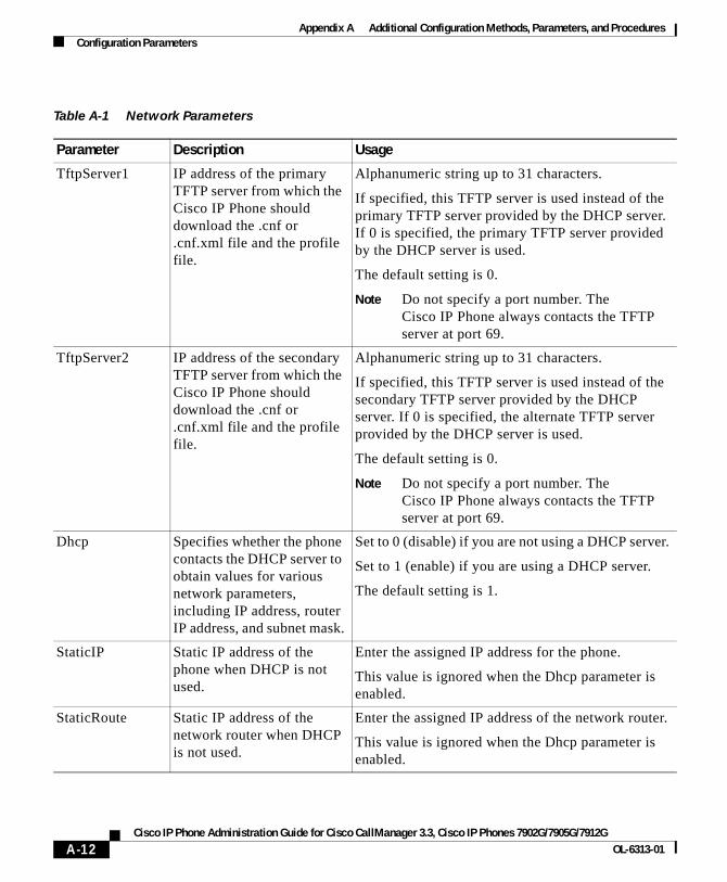
Appendix A Additional Configuration Methods, Parameters, and ProceduresConfiguration Parameters
Table A-1 Network Parameters
Parameter Description Usage
TftpServer1 IP address of the primary TFTP server from which the Cisco IP Phone should download the .cnf or .cnf.xml file and the profile file.
Alphanumeric string up to 31 characters.
If specified, this TFTP server is used instead of the primary TFTP server provided by the DHCP server. If 0 is specified, the primary TFTP server provided by the DHCP server is used.
The default setting is 0.
Note Do not specify a port number. The Cisco IP Phone always contacts the TFTP server at port 69.
TftpServer2 IP address of the secondary TFTP server from which the Cisco IP Phone should download the .cnf or .cnf.xml file and the profile file.
Alphanumeric string up to 31 characters.
If specified, this TFTP server is used instead of the secondary TFTP server provided by the DHCP server. If 0 is specified, the alternate TFTP server provided by the DHCP server is used.
The default setting is 0.
Note Do not specify a port number. The Cisco IP Phone always contacts the TFTP server at port 69.
Dhcp Specifies whether the phone contacts the DHCP server to obtain values for various network parameters, including IP address, router IP address, and subnet mask.
Set to 0 (disable) if you are not using a DHCP server.
Set to 1 (enable) if you are using a DHCP server.
The default setting is 1.
StaticIP Static IP address of the phone when DHCP is not used.
Enter the assigned IP address for the phone.
This value is ignored when the Dhcp parameter is enabled.
StaticRoute Static IP address of the network router when DHCP is not used.
Enter the assigned IP address of the network router.
This value is ignored when the Dhcp parameter is enabled.
A-12Cisco IP Phone Administration Guide for Cisco CallManager 3.3, Cisco IP Phones 7902G/7905G/7912G
OL-6313-01
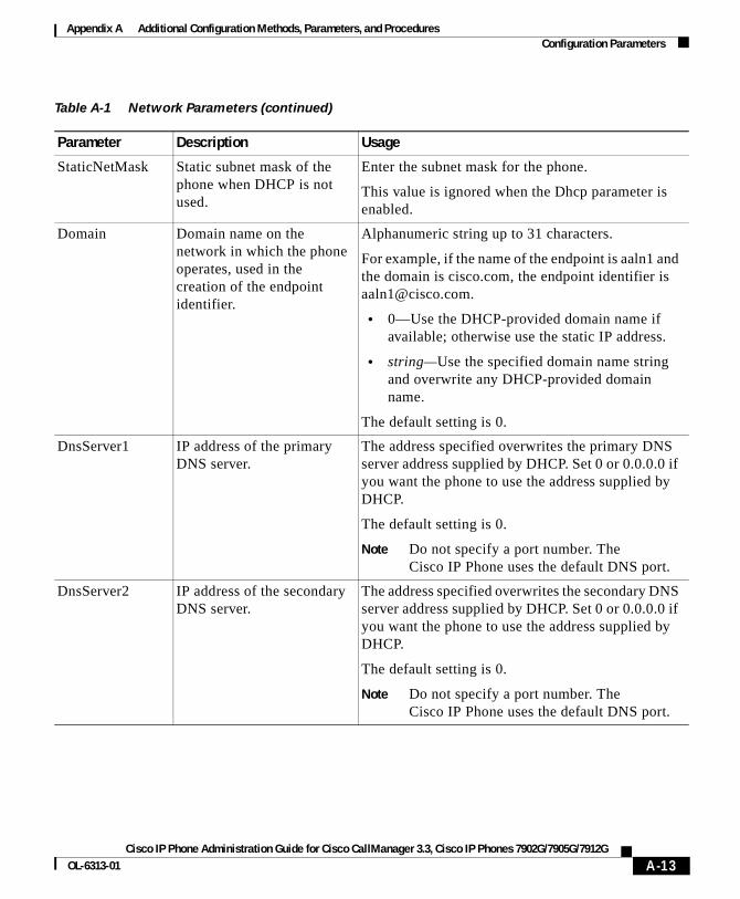
Appendix A Additional Configuration Methods, Parameters, and ProceduresConfiguration Parameters
StaticNetMask Static subnet mask of the phone when DHCP is not used.
Enter the subnet mask for the phone.
This value is ignored when the Dhcp parameter is enabled.
Domain Domain name on the network in which the phone operates, used in the creation of the endpoint identifier.
Alphanumeric string up to 31 characters.
For example, if the name of the endpoint is aaln1 and the domain is cisco.com, the endpoint identifier is [email protected].
• 0—Use the DHCP-provided domain name if available; otherwise use the static IP address.
• string—Use the specified domain name string and overwrite any DHCP-provided domain name.
The default setting is 0.
DnsServer1 IP address of the primary DNS server.
The address specified overwrites the primary DNS server address supplied by DHCP. Set 0 or 0.0.0.0 if you want the phone to use the address supplied by DHCP.
The default setting is 0.
Note Do not specify a port number. The Cisco IP Phone uses the default DNS port.
DnsServer2 IP address of the secondary DNS server.
The address specified overwrites the secondary DNS server address supplied by DHCP. Set 0 or 0.0.0.0 if you want the phone to use the address supplied by DHCP.
The default setting is 0.
Note Do not specify a port number. The Cisco IP Phone uses the default DNS port.
Table A-1 Network Parameters (continued)
Parameter Description Usage
A-13Cisco IP Phone Administration Guide for Cisco CallManager 3.3, Cisco IP Phones 7902G/7905G/7912G
OL-6313-01
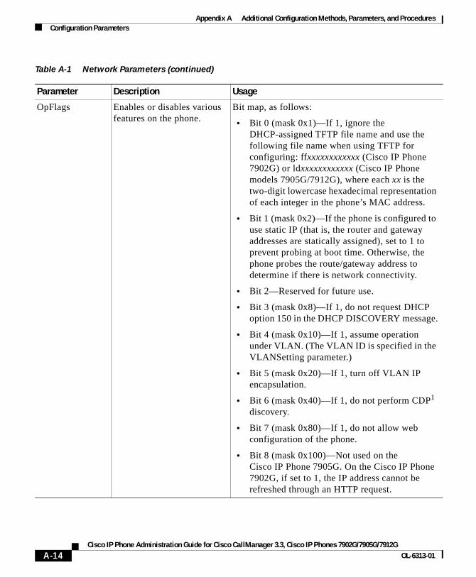
Appendix A Additional Configuration Methods, Parameters, and ProceduresConfiguration Parameters
OpFlags Enables or disables various features on the phone.
Bit map, as follows:
• Bit 0 (mask 0x1)—If 1, ignore the DHCP-assigned TFTP file name and use the following file name when using TFTP for configuring: ffxxxxxxxxxxxx (Cisco IP Phone 7902G) or ldxxxxxxxxxxxx (Cisco IP Phone models 7905G/7912G), where each xx is the two-digit lowercase hexadecimal representation of each integer in the phone’s MAC address.
• Bit 1 (mask 0x2)—If the phone is configured to use static IP (that is, the router and gateway addresses are statically assigned), set to 1 to prevent probing at boot time. Otherwise, the phone probes the route/gateway address to determine if there is network connectivity.
• Bit 2—Reserved for future use.
• Bit 3 (mask 0x8)—If 1, do not request DHCP option 150 in the DHCP DISCOVERY message.
• Bit 4 (mask 0x10)—If 1, assume operation under VLAN. (The VLAN ID is specified in the VLANSetting parameter.)
• Bit 5 (mask 0x20)—If 1, turn off VLAN IP encapsulation.
• Bit 6 (mask 0x40)—If 1, do not perform CDP1 discovery.
• Bit 7 (mask 0x80)—If 1, do not allow web configuration of the phone.
• Bit 8 (mask 0x100)—Not used on the Cisco IP Phone 7905G. On the Cisco IP Phone 7902G, if set to 1, the IP address cannot be refreshed through an HTTP request.
Table A-1 Network Parameters (continued)
Parameter Description Usage
A-14Cisco IP Phone Administration Guide for Cisco CallManager 3.3, Cisco IP Phones 7902G/7905G/7912G
OL-6313-01
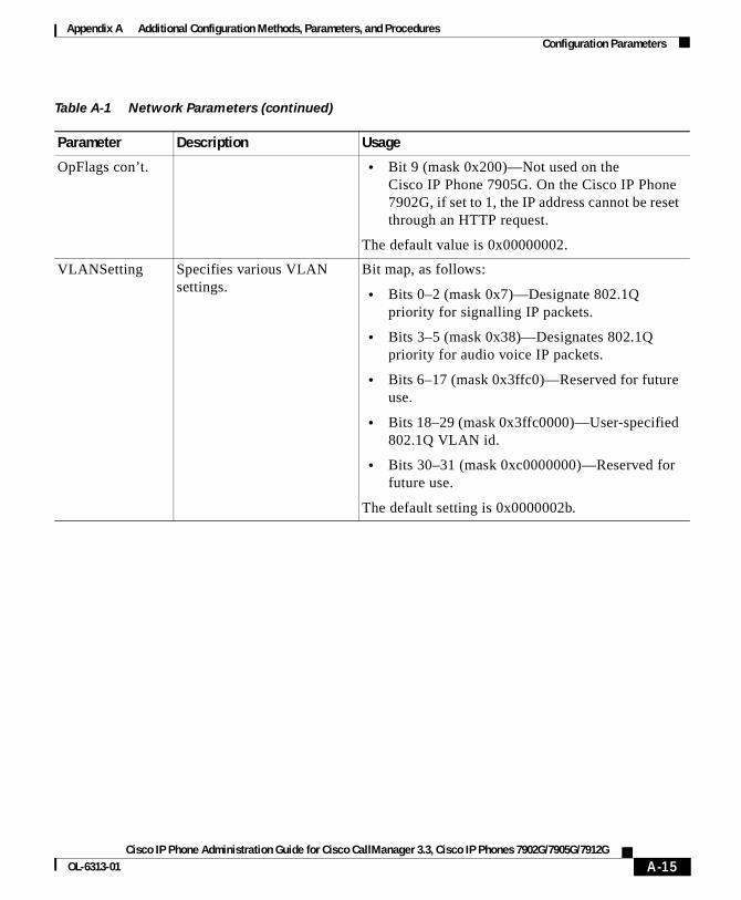
Appendix A Additional Configuration Methods, Parameters, and ProceduresConfiguration Parameters
OpFlags con’t. • Bit 9 (mask 0x200)—Not used on the Cisco IP Phone 7905G. On the Cisco IP Phone 7902G, if set to 1, the IP address cannot be reset through an HTTP request.
The default value is 0x00000002.
VLANSetting Specifies various VLAN settings.
Bit map, as follows:
• Bits 0–2 (mask 0x7)—Designate 802.1Q priority for signalling IP packets.
• Bits 3–5 (mask 0x38)—Designates 802.1Q priority for audio voice IP packets.
• Bits 6–17 (mask 0x3ffc0)—Reserved for future use.
• Bits 18–29 (mask 0x3ffc0000)—User-specified 802.1Q VLAN id.
• Bits 30–31 (mask 0xc0000000)—Reserved for future use.
The default setting is 0x0000002b.
Table A-1 Network Parameters (continued)
Parameter Description Usage
A-15Cisco IP Phone Administration Guide for Cisco CallManager 3.3, Cisco IP Phones 7902G/7905G/7912G
OL-6313-01
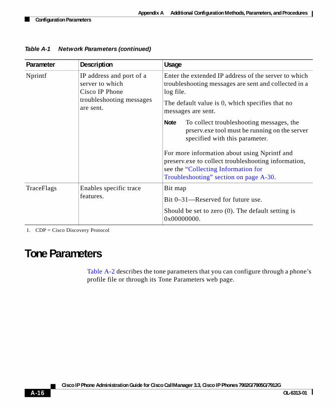
Appendix A Additional Configuration Methods, Parameters, and ProceduresConfiguration Parameters
Tone Parameters Table A-2 describes the tone parameters that you can configure through a phone’s profile file or through its Tone Parameters web page.
Nprintf IP address and port of a server to which Cisco IP Phone troubleshooting messages are sent.
Enter the extended IP address of the server to which troubleshooting messages are sent and collected in a log file.
The default value is 0, which specifies that no messages are sent.
Note To collect troubleshooting messages, the prserv.exe tool must be running on the server specified with this parameter.
For more information about using Nprintf and preserv.exe to collect troubleshooting information, see the “Collecting Information for Troubleshooting” section on page A-30.
TraceFlags Enables specific trace features.
Bit map
Bit 0–31—Reserved for future use.
Should be set to zero (0). The default setting is 0x00000000.
1. CDP = Cisco Discovery Protocol
Table A-1 Network Parameters (continued)
Parameter Description Usage
A-16Cisco IP Phone Administration Guide for Cisco CallManager 3.3, Cisco IP Phones 7902G/7905G/7912G
OL-6313-01
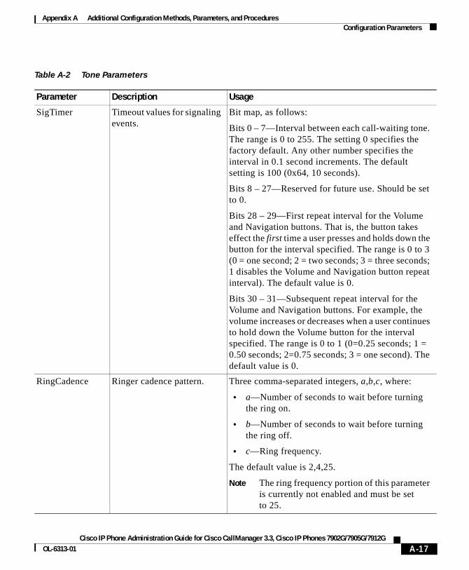
Appendix A Additional Configuration Methods, Parameters, and ProceduresConfiguration Parameters
Table A-2 Tone Parameters
Parameter Description Usage
SigTimer Timeout values for signaling events.
Bit map, as follows:
Bits 0 – 7—Interval between each call-waiting tone. The range is 0 to 255. The setting 0 specifies the factory default. Any other number specifies the interval in 0.1 second increments. The default setting is 100 (0x64, 10 seconds).
Bits 8 – 27—Reserved for future use. Should be set to 0.
Bits 28 – 29—First repeat interval for the Volume and Navigation buttons. That is, the button takes effect the first time a user presses and holds down the button for the interval specified. The range is 0 to 3 (0 = one second; 2 = two seconds; 3 = three seconds; 1 disables the Volume and Navigation button repeat interval). The default value is 0.
Bits 30 – 31—Subsequent repeat interval for the Volume and Navigation buttons. For example, the volume increases or decreases when a user continues to hold down the Volume button for the interval specified. The range is 0 to 1 (0=0.25 seconds; 1 = 0.50 seconds; 2=0.75 seconds; 3 = one second). The default value is 0.
RingCadence Ringer cadence pattern. Three comma-separated integers, a,b,c, where:
• a—Number of seconds to wait before turning the ring on.
• b—Number of seconds to wait before turning the ring off.
• c—Ring frequency.
The default value is 2,4,25.
Note The ring frequency portion of this parameter is currently not enabled and must be set to 25.
A-17Cisco IP Phone Administration Guide for Cisco CallManager 3.3, Cisco IP Phones 7902G/7905G/7912G
OL-6313-01
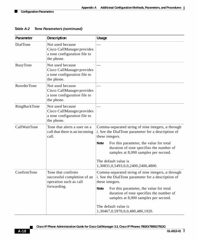
Appendix A Additional Configuration Methods, Parameters, and ProceduresConfiguration Parameters
DialTone Not used because Cisco CallManager provides a tone configuration file to the phone.
—
BusyTone Not used because Cisco CallManager provides a tone configuration file to the phone.
—
ReorderTone Not used because Cisco CallManager provides a tone configuration file to the phone.
—
RingBackTone Not used because Cisco CallManager provides a tone configuration file to the phone.
—
CallWaitTone Tone that alerts a user on a call that there is an incoming call.
Comma-separated string of nine integers, a through i. See the DialTone parameter for a description of these integers.
Note For this parameter, the value for total duration of tone specifies the number of samples at 8,000 samples per second.
The default value is 1,30831,0,5493,0,0,2400,2400,4800.
ConfirmTone Tone that confirms successful completion of an operation such as call forwarding.
Comma-separated string of nine integers, a through i. See the DialTone parameter for a description of these integers.
Note For this parameter, the value for total duration of tone specifies the number of samples at 8,000 samples per second.
The default value is 1,30467,0,5970,0,0,480,480,1920.
Table A-2 Tone Parameters (continued)
Parameter Description Usage
A-18Cisco IP Phone Administration Guide for Cisco CallManager 3.3, Cisco IP Phones 7902G/7905G/7912G
OL-6313-01

Appendix A Additional Configuration Methods, Parameters, and ProceduresConfiguration Parameters
Audio ParametersTable A-3 describes the network parameters that you can configure through a phone’s profile file or through its Audio Parameters web page.
Table A-3 Audio Parameters
Parameter Description Usage
AudioMode Allows control of audio-related functions.
Bit map, as follows:
• Bit 0 (mask 0x1)—If 0, disable G.711 or G.729 silence suppression. If 1, enable G.711 or G.729 silence suppression. The default setting is 1
• Bit 1 (mask 0x2)—If 0, use G.711 codec only; do not use low-bit-rate codec. If 1, use both G.711 and low-bit-rate codec.
• Bits 2–3 (mask 0x4)—Reserved for future use.
• Bits 4–5 (mask 0x30): DTMF transmission method:
– 0—Always in-band.
– 1—By negotiation.
– 2—Always out-of-band.
– 3—Neither in-band nor out-of-band.
• Bits 6–31—Reserved for future use.
A-19Cisco IP Phone Administration Guide for Cisco CallManager 3.3, Cisco IP Phones 7902G/7905G/7912G
OL-6313-01
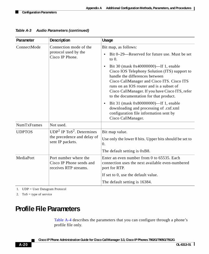
Appendix A Additional Configuration Methods, Parameters, and ProceduresConfiguration Parameters
Profile File ParametersTable A-4 describes the parameters that you can configure through a phone’s profile file only.
ConnectMode Connection mode of the protocol used by the Cisco IP Phone.
Bit map, as follows:
• Bit 0–29—Reserved for future use. Must be set to 0.
• Bit 30 (mask 0x40000000)—If 1, enable Cisco IOS Telephony Solution (ITS) support to handle the differences between Cisco CallManager and Cisco ITS. Cisco ITS runs on an IOS router and is a subset of Cisco CallManager. If you have Cisco ITS, refer to the documentation for that product.
• Bit 31 (mask 0x80000000)—If 1, enable downloading and processing of .cnf.xml configuration file information sent by Cisco CallManager.
NumTxFrames Not used.
UDPTOS UDP1 IP ToS2. Determines the precedence and delay of sent IP packets.
Bit map value.
Use only the lower 8 bits. Upper bits should be set to 0.
The default setting is 0xB8.
MediaPort Port number where the Cisco IP Phone sends and receives RTP streams.
Enter an even number from 0 to 65535. Each connection uses the next available even-numbered port for RTP.
If set to 0, use the default value.
The default setting is 16384.
1. UDP = User Datagram Protocol
2. ToS = type of service
Table A-3 Audio Parameters (continued)
Parameter Description Usage
A-20Cisco IP Phone Administration Guide for Cisco CallManager 3.3, Cisco IP Phones 7902G/7905G/7912G
OL-6313-01
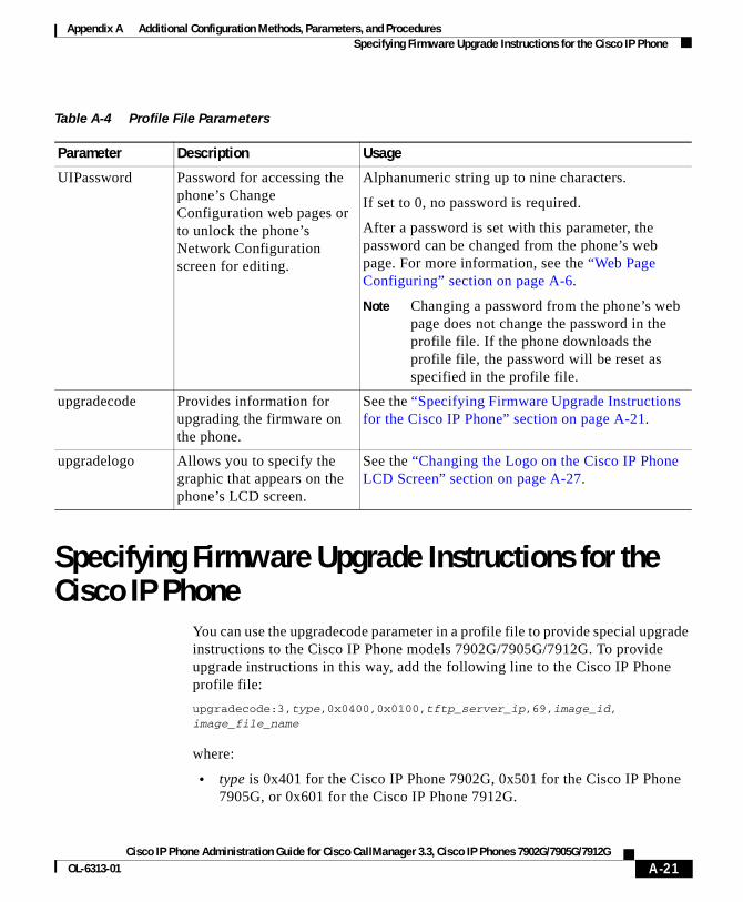
Appendix A Additional Configuration Methods, Parameters, and ProceduresSpecifying Firmware Upgrade Instructions for the Cisco IP Phone
Specifying Firmware Upgrade Instructions for the Cisco IP Phone
You can use the upgradecode parameter in a profile file to provide special upgrade instructions to the Cisco IP Phone models 7902G/7905G/7912G. To provide upgrade instructions in this way, add the following line to the Cisco IP Phone profile file:
upgradecode:3,type,0x0400,0x0100,tftp_server_ip,69,image_id,image_file_name
where:
• type is 0x401 for the Cisco IP Phone 7902G, 0x501 for the Cisco IP Phone 7905G, or 0x601 for the Cisco IP Phone 7912G.
Table A-4 Profile File Parameters
Parameter Description Usage
UIPassword Password for accessing the phone’s Change Configuration web pages or to unlock the phone’s Network Configuration screen for editing.
Alphanumeric string up to nine characters.
If set to 0, no password is required.
After a password is set with this parameter, the password can be changed from the phone’s web page. For more information, see the “Web Page Configuring” section on page A-6.
Note Changing a password from the phone’s web page does not change the password in the profile file. If the phone downloads the profile file, the password will be reset as specified in the profile file.
upgradecode Provides information for upgrading the firmware on the phone.
See the “Specifying Firmware Upgrade Instructions for the Cisco IP Phone” section on page A-21.
upgradelogo Allows you to specify the graphic that appears on the phone’s LCD screen.
See the “Changing the Logo on the Cisco IP Phone LCD Screen” section on page A-27.
A-21Cisco IP Phone Administration Guide for Cisco CallManager 3.3, Cisco IP Phones 7902G/7905G/7912G
OL-6313-01
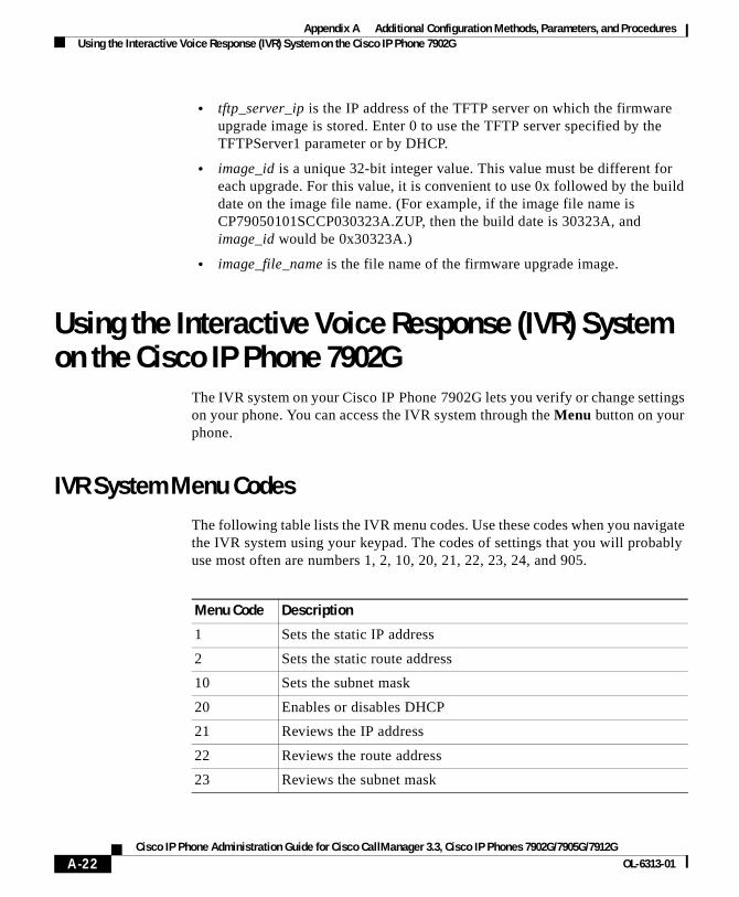
Appendix A Additional Configuration Methods, Parameters, and ProceduresUsing the Interactive Voice Response (IVR) System on the Cisco IP Phone 7902G
• tftp_server_ip is the IP address of the TFTP server on which the firmware upgrade image is stored. Enter 0 to use the TFTP server specified by the TFTPServer1 parameter or by DHCP.
• image_id is a unique 32-bit integer value. This value must be different for each upgrade. For this value, it is convenient to use 0x followed by the build date on the image file name. (For example, if the image file name is CP79050101SCCP030323A.ZUP, then the build date is 30323A, and image_id would be 0x30323A.)
• image_file_name is the file name of the firmware upgrade image.
Using the Interactive Voice Response (IVR) System on the Cisco IP Phone 7902G
The IVR system on your Cisco IP Phone 7902G lets you verify or change settings on your phone. You can access the IVR system through the Menu button on your phone.
IVR System Menu CodesThe following table lists the IVR menu codes. Use these codes when you navigate the IVR system using your keypad. The codes of settings that you will probably use most often are numbers 1, 2, 10, 20, 21, 22, 23, 24, and 905.
Menu Code Description
1 Sets the static IP address
2 Sets the static route address
10 Sets the subnet mask
20 Enables or disables DHCP
21 Reviews the IP address
22 Reviews the route address
23 Reviews the subnet mask
A-22Cisco IP Phone Administration Guide for Cisco CallManager 3.3, Cisco IP Phones 7902G/7905G/7912G
OL-6313-01
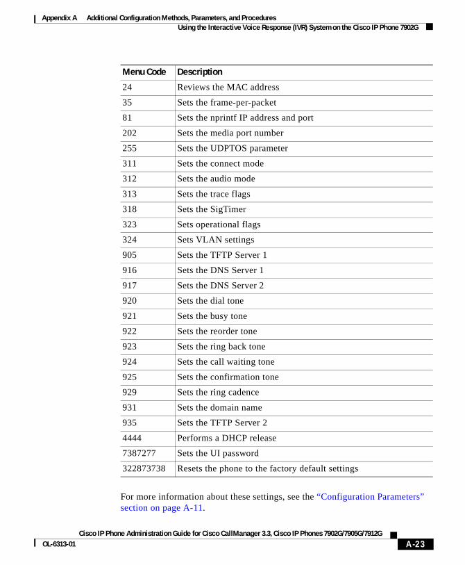
Appendix A Additional Configuration Methods, Parameters, and ProceduresUsing the Interactive Voice Response (IVR) System on the Cisco IP Phone 7902G
For more information about these settings, see the “Configuration Parameters” section on page A-11.
24 Reviews the MAC address
35 Sets the frame-per-packet
81 Sets the nprintf IP address and port
202 Sets the media port number
255 Sets the UDPTOS parameter
311 Sets the connect mode
312 Sets the audio mode
313 Sets the trace flags
318 Sets the SigTimer
323 Sets operational flags
324 Sets VLAN settings
905 Sets the TFTP Server 1
916 Sets the DNS Server 1
917 Sets the DNS Server 2
920 Sets the dial tone
921 Sets the busy tone
922 Sets the reorder tone
923 Sets the ring back tone
924 Sets the call waiting tone
925 Sets the confirmation tone
929 Sets the ring cadence
931 Sets the domain name
935 Sets the TFTP Server 2
4444 Performs a DHCP release
7387277 Sets the UI password
322873738 Resets the phone to the factory default settings
Menu Code Description
A-23Cisco IP Phone Administration Guide for Cisco CallManager 3.3, Cisco IP Phones 7902G/7905G/7912G
OL-6313-01
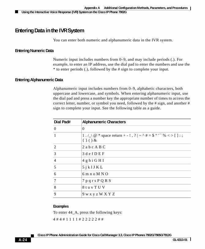
Appendix A Additional Configuration Methods, Parameters, and ProceduresUsing the Interactive Voice Response (IVR) System on the Cisco IP Phone 7902G
Entering Data in the IVR System
You can enter both numeric and alphanumeric data in the IVR system.
Entering Numeric Data
Numeric input includes numbers from 0–9, and may include periods (.). For example, to enter an IP address, use the dial pad to enter the numbers and use the * to enter periods (.), followed by the # sign to complete your input.
Entering Alphanumeric Data
Alphanumeric input includes numbers from 0–9, alphabetic characters, both uppercase and lowercase, and symbols. When entering alphanumeric input, use the dial pad and press a number key the appropriate number of times to access the correct letter, number, or symbol you need, followed by the # sign, and another # sign to complete your input. See the following table as a guide.
Examples
To enter 44_A, press the following keys:
4 # 4 # 1 1 1 1 # 2 2 2 2 2 # #
Dial Pad# Alphanumeric Characters
0 0
1 1 . /_\ @ * space return + - ! , ? | ~ ^ # = $ “ ' ` % < > [ ] : ;{ } ( ) &
2 2 a b c A B C
3 3 d e f D E F
4 4 g h i G H I
5 5 j k l J K L
6 6 m n o M N O
7 7 p q r s P Q R S
8 8 t u v T U V
9 9 w x y z W X Y Z
A-24Cisco IP Phone Administration Guide for Cisco CallManager 3.3, Cisco IP Phones 7902G/7905G/7912G
OL-6313-01
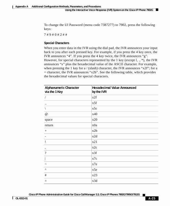
Appendix A Additional Configuration Methods, Parameters, and ProceduresUsing the Interactive Voice Response (IVR) System on the Cisco IP Phone 7902G
To change the UI Password (menu code 7387277) to 7902, press the following keys:
7 # 9 # 0 # 2 # #
Special Characters
When you enter data in the IVR using the dial pad, the IVR announces your input back to you after each pressed key. For example, if you press the 4 key once, the IVR announces “4”. If you press the 4 key twice, the IVR announces “g”. However, for special characters represented by the 1 key (except l, ., *), the IVR announces “x” plus the hexadecimal value of the ASCII character. For example, when pressing the 1 key for a / (slash) character, the IVR announces “x2f”; for a + character, the IVR announces “x2b”. See the following table, which provides the hexadecimal values for special characters.
Alphanumeric Character via the 1 Key
Hexadecimal Value Announcedby the IVR
/ x2f
_ x5f
\ x5c
@ x40
space x20
return x0a
+ x2b
- x2d
! x21
, x2c
? x3f
| x7c
~ x7e
^ x5e
# x23
= x3d
A-25Cisco IP Phone Administration Guide for Cisco CallManager 3.3, Cisco IP Phones 7902G/7905G/7912G
OL-6313-01
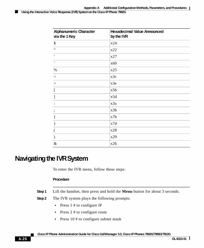
Appendix A Additional Configuration Methods, Parameters, and ProceduresUsing the Interactive Voice Response (IVR) System on the Cisco IP Phone 7902G
Navigating the IVR SystemTo enter the IVR menu, follow these steps:
Procedure
Step 1 Lift the handset, then press and hold the Menu button for about 3 seconds.
Step 2 The IVR system plays the following prompts:
• Press 1 # to configure IP
• Press 2 # to configure route
• Press 10 # to configure subnet mask
$ x24
“ x22
' x27
` x60
% x25
< x3c
> x3e
[ x5b
] x5d
: x3a
; x3b
{ x7b
} x7d
( x28
) x29
& x26
Alphanumeric Character via the 1 Key
Hexadecimal Value Announcedby the IVR
A-26Cisco IP Phone Administration Guide for Cisco CallManager 3.3, Cisco IP Phones 7902G/7905G/7912G
OL-6313-01
Appendix A Additional Configuration Methods, Parameters, and ProceduresChanging the Logo on the Cisco IP Phone LCD Screen
• Press 20 # to configure DHCP
• Press # to go to the extended menu
Step 3 Enter the voice menu code for the setting that you want to verify or change, and then press #.
Note Use the * key to toggle between alphanumeric and numeric input mode. For example, when you enter 905 #, the IVR prompts you for alphanumeric input. When you enter 905 * #, the IVR prompts you for numeric data.
Step 4 Follow the prompts and enter the appropriate values.
Step 5 The IVR repeats the value you entered, then prompts you to press one of the following keys:
• 1=Change your entered value
• 2=Review your entered value
• 3=Save your entered value
• 4=Review the current saved value
Step 6 Hang up the phone. The phone resets.
Changing the Logo on the Cisco IP Phone LCD Screen
Note This section does not apply to the Cisco IP Phone 7902G.
When the Cisco IP Phone models 7905G and 7912G are not in use for a call, a graphic appears on the LCD screen. Using TFTP configuring, you can change this graphic to one that you provide. For example, you might change the graphic to your company logo.
A-27Cisco IP Phone Administration Guide for Cisco CallManager 3.3, Cisco IP Phones 7902G/7905G/7912G
OL-6313-01
Appendix A Additional Configuration Methods, Parameters, and ProceduresChanging the Logo on the Cisco IP Phone LCD Screen
Before you can change the graphic on the phone, you must use a graphics program to create an image with the following attributes:
• Width of 88 pixels.
• Height of 27 pixels.
• Monochrome (black-and-white).
• Saved as bitmap file with the extension .bmp. For example, mylogo.bmp.
In addition, you will need the bmp2logo.exe tool, which converts your bitmap image file to a .logo file that can be downloaded to the phone. This tool is bundled with the Cisco IP Phone software. You can also obtain it from the CCO website at the following URL. It is included with the SCCP Software Package Zip file.
http://www.cisco.com/cgi-bin/tablebuild.pl/ip_phone_client
To change the graphic that appears on a Cisco IP Phone, follow these steps:
Procedure
Step 1 Open a command window and type the following command:
bmp2logo imageID image.bmp image.logo
where:
• imageID is a unique identifier for the new graphic. This identifier must be a number from 0 through 4294967296 and must be different than the identifier of the graphic that is currently on the phone.
• image is the base file name of the image that you previously created and saved with the graphics program.
Note The imageID of the image that comes with the phone is 1.
For example, if the image identifier is 10 and the base name of your image file is mylogo, type this command:
bmp2logo 10 mylogo.bmp mylogo.logo
Step 2 Copy the image.logo file to the TFTPPATH directory on the TFTP server.
A-28Cisco IP Phone Administration Guide for Cisco CallManager 3.3, Cisco IP Phones 7902G/7905G/7912G
OL-6313-01

Appendix A Additional Configuration Methods, Parameters, and ProceduresChanging the Logo on the Cisco IP Phone LCD Screen
Step 3 Add the following line to the Cisco IP Phone profile file.
Note For detailed information about using profile files, see the “TFTP Configuring” section on page A-2.
upgradelogo:imageID,TFTPServerID,image.logo
where:
• imageID is the same unique identifier that you specified in Step 1.
• TFTPServerID is the IP address of the TFTP server on which the image.logo file is stored. If the image.logo file is stored on the same TFTP server as the Cisco IP Phone configuration file, replace TFTPServerID with the numeral 0.
• image is the base file name of the image file.
For example, if the image identifier is 10, the converted file is stored on the same TFTP server as the Cisco IP Phone configuration file, and the base name of the converted image file is mylogo, add the following line to the configuration file:
upgradelogo:10,0,mylogo.logo
Step 4 Use the cfgfmt.exe tool to generate a binary profile file from the text file.
Put the binary file in these locations:
• The root directory on the TFTP server (C:\Program Files\cisco\tftppath)
• The network locale directories on the TFTP server for each language that is supported by Cisco CallManager.
The default network locale directory on the TFTP server is C:\Program Files\ cisco\tftppath\United_States.
Note For detailed information about using the cfgfmt.exe tool, see the “Editing a Profile File and Converting it to Binary Format” section on page A-5.
Step 5 Power cycle the phone.
The new graphic appears when the phone restarts.
A-29Cisco IP Phone Administration Guide for Cisco CallManager 3.3, Cisco IP Phones 7902G/7905G/7912G
OL-6313-01
Appendix A Additional Configuration Methods, Parameters, and ProceduresCollecting Information for Troubleshooting
Collecting Information for TroubleshootingYou can collect information relating to the operations of the Cisco IP Phone models 7902G/7905G/7912G and store this information in a log file on a server that you specify. If you experience a problem with a phone, this information can be useful for troubleshooting.
To collect information for troubleshooting, you will need the nprintf.exe tool. This tool is bundled with the Cisco IP Phone software. You can also obtain this tool from the CCO website. It is included with the SCCP Software Package Zip file.
To collect troubleshooting information in a log file, follow these steps:
Step 1 Add the following line to the Cisco IP Phone profile file:
Nprintf:IPaddress.listen_port
where:
• IPaddress is the IP address of the server to which information will be sent.
• listen_port is the port to which information is sent on the server specified.
For example, if you want to send information port 9001 on a server with an IP address of 192.168.2.170, set the Nprintf parameter to 192.168.2.170.9001.
Note If you set this parameter to 0 or to 0.0.0.0.0, no information will be sent from the phone.
A-30Cisco IP Phone Administration Guide for Cisco CallManager 3.3, Cisco IP Phones 7902G/7905G/7912G
OL-6313-01
Appendix A Additional Configuration Methods, Parameters, and ProceduresCollecting Information for Troubleshooting
Step 2 On the server that will receive information, open a command window and type the following command:
prserv [listen-port]
where listen_port is the same port that you specified with the Nprintf parameter.
If you do not specify a port, 9001 is used by default.
While pserv is running, information from the Cisco IP Phone is sent to a file named listen-port.log, where listen-port is the port you specified with the Nprintf parameter and the prserv command. This file is stored on the server you specified with the Nprintf parameter in the folder from which you ran the preserv command. If the file exists, new information is appended to it.
You can open a listen-port.log file using a text editor.
Step 3 To exit prserv.exe and stop collecting information, press Ctrl-C in the command window.
A-31Cisco IP Phone Administration Guide for Cisco CallManager 3.3, Cisco IP Phones 7902G/7905G/7912G
OL-6313-01
Appendix A Additional Configuration Methods, Parameters, and ProceduresCollecting Information for Troubleshooting
Note If you want to collect information from more than one Cisco IP Phone, it is recommended that you store information in a separate listen-port.log file for each phone. If you store all information in a single file, it can be difficult to identify which messages belong to which phones. To generate separate listen-port.log files, configure each phone using its own profile file or web page. For each phone, use the Nprintf parameter in the profile file or web pate to specify a unique port number on the server to which information will be sent. Then, run prserv.exe multiple times, once for each phone from which you want to collect information. Run each instance of preserv.exe in its own command window. For each instance, make sure to specify a port number that corresponds to a port number in a Nprintf parameter.
A-32Cisco IP Phone Administration Guide for Cisco CallManager 3.3, Cisco IP Phones 7902G/7905G/7912G
OL-6313-01
Cisco IP Phone Administration Guide for Cisco CallManager 3OL-6313-01
A
P P E N D I X B Technical SpecificationsThe following sections describe the technical specifications for the Cisco IP Phone models 7902G/7905G/7912G.
• Physical and Operating Environment Specifications, page B-1
• Cable Specifications, page B-2
• Network Port Pinouts, page B-2
Physical and Operating Environment SpecificationsTable B-1 shows the physical and operating environment specifications for the Cisco IP Phone models 7902G/7905G/7912G.
Table B-1 Physical and Operating Specification
Specification Value or Range
Operating temperature 0° to 40°C (32° to 104°F)
Operating relative humidity
10% to 95% (non-condensing)
Storage temperature -10° to 60°C (14° to 140°F)
Height 20.32 cm (8 in.)
Width 17.67 cm (7 in.)
Depth 15.24 cm (6 in.)
Weight 0.9 kg (1.9 lb)
B-1.3, Cisco IP Phones 7902G/7905G/7912G
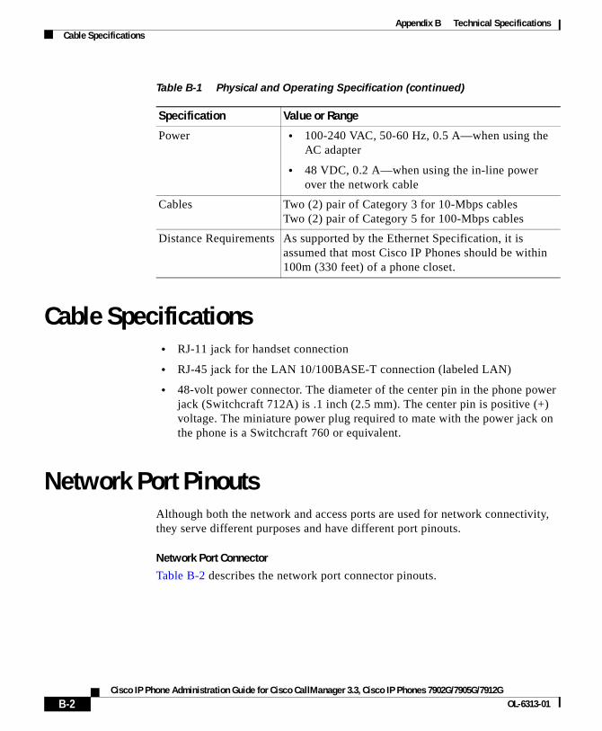
Appendix B Technical SpecificationsCable Specifications
Cable Specifications• RJ-11 jack for handset connection
• RJ-45 jack for the LAN 10/100BASE-T connection (labeled LAN)
• 48-volt power connector. The diameter of the center pin in the phone power jack (Switchcraft 712A) is .1 inch (2.5 mm). The center pin is positive (+) voltage. The miniature power plug required to mate with the power jack on the phone is a Switchcraft 760 or equivalent.
Network Port PinoutsAlthough both the network and access ports are used for network connectivity, they serve different purposes and have different port pinouts.
Network Port Connector
Table B-2 describes the network port connector pinouts.
Power • 100-240 VAC, 50-60 Hz, 0.5 A—when using the AC adapter
• 48 VDC, 0.2 A—when using the in-line power over the network cable
Cables Two (2) pair of Category 3 for 10-Mbps cablesTwo (2) pair of Category 5 for 100-Mbps cables
Distance Requirements As supported by the Ethernet Specification, it is assumed that most Cisco IP Phones should be within 100m (330 feet) of a phone closet.
Table B-1 Physical and Operating Specification (continued)
Specification Value or Range
B-2Cisco IP Phone Administration Guide for Cisco CallManager 3.3, Cisco IP Phones 7902G/7905G/7912G
OL-6313-01
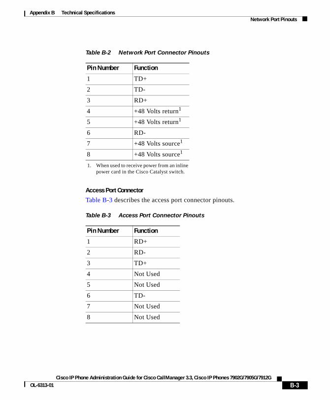
Appendix B Technical SpecificationsNetwork Port Pinouts
Access Port Connector
Table B-3 describes the access port connector pinouts.
Table B-2 Network Port Connector Pinouts
Pin Number Function
1 TD+
2 TD-
3 RD+
4 +48 Volts return1
1. When used to receive power from an inline power card in the Cisco Catalyst switch.
5 +48 Volts return1
6 RD-
7 +48 Volts source1
8 +48 Volts source1
Table B-3 Access Port Connector Pinouts
Pin Number Function
1 RD+
2 RD-
3 TD+
4 Not Used
5 Not Used
6 TD-
7 Not Used
8 Not Used
B-3Cisco IP Phone Administration Guide for Cisco CallManager 3.3, Cisco IP Phones 7902G/7905G/7912G
OL-6313-01

Appendix B Technical SpecificationsNetwork Port Pinouts
B-4Cisco IP Phone Administration Guide for Cisco CallManager 3.3, Cisco IP Phones 7902G/7905G/7912G
OL-6313-01
Cisco IP Phone Administration Guide for Cisco CallManager 3.3OL-6313-01
I N D E X
A
AC adapter
connecting to 3-5
providing power using 2-9
access port
connecting 3-5
purpose 2-9
active Cisco CallManager server, description 4-8
adding
Cisco IP Phones manually 2-14
Cisco IP Phones using auto-registration 2-12
Cisco IP Phones using Bulk Administration Tool 2-17
Cisco IP Phones using DHCP 2-14
users to Cisco CallManager 5-7
administrative VLAN, description 4-6
alternate TFTP, network setting 4-9
App Load ID A-8
assigning
default router 4-17
DNS servers 4-22
domain name 4-20
IP address 4-15
subnet mask 4-19
TFTP server 4-28
audience, for this document xi
AudioMode parameter A-19
audio parameter
AudioMode A-19
ConnectMode A-20
MediaPort A-20
NumTxFrames A-20
UDPTOS A-20
auto answer, description 5-3
auto-registration, using 2-12
auxiliary VLAN
description 2-3
network setting 4-6
B
BAT, adding phones with 2-17
bmp2logo.exe A-28
Boot Load ID A-8
BOOTP server A-8
BootP Server, network setting 4-5
Broadcast A-10
BTXML cards version A-8
IN-1, Cisco IP Phones 7902G/7905G/7912G
Index
Bulk Administration Tool, adding phones with 2-17
BusyTone parameter A-18
C
caller ID, description 5-4
CallManager 1 – 4 A-9
call park, description 5-3
call pickup, description 5-3
call waiting, description 5-4
CallWaitTone parameter A-18
caution, cell phone interference 1-1
CDP, description 1-7
CDP discovery A-14
cell phone, interference 1-1
cfgfmt.exe A-5
Cisco Call Back 5-4
Cisco CallManager
active, description 4-8
adding phone to database of 2-12
context-sensitive help for 2-12
interactions with 2-2
required for Cisco IP Phones 3-2
standby description 4-8
verifying settings 6-16
Cisco Catalyst switches, interaction with 2-3
Cisco discovery protocol (CDP), description 1-7
IN-2Cisco IP Phone Administration Guide for Cisco CallM
Cisco IP Phone
adding manually to Cisco CallManager 2-14
adding to Cisco CallManager 2-12
configuration requirements 1-12
installation overview 1-12
installation procedure 3-4
installation requirements 1-12
mounting to wall 3-8
power sources 2-9
registering 2-12
registering with Cisco CallManager 2-12
resetting 6-8
supported networking protocols 1-7
technical specifications B-1
troubleshooting 6-1
Cisco IP Phone 7902G
features 1-2
figure 1-2, 3-6
upgrading firmware A-21
Cisco IP Phone 7905G
features 1-2, 1-4
figure 1-2, 1-4, 3-6
graphic on LCD screen A-27
upgrading firmware A-21
Cisco IP Phone 7912G
features 1-4
figure 1-4, 3-7
graphic on LCD screen A-27
upgrading firmware A-21
anager 3.3, Cisco IP Phones 7902G/7905G/7912GOL-6313-01
Index
conference, description 5-4
configuration file, creating 6-17
configuration parameter
See parameter
configuring
alternate methods A-1
from a Cisco IP Phone 4-2
methods 4-1
overview 1-12
startup network settings 3-10
through phone’s web page 4-3, A-6
user features 5-7
VLAN settings 4-24
ConfirmTone parameter A-18
connecting
handset 3-4
to AC adapter 3-5
to a computer 3-5
to the network 3-4
ConnectMode parameter A-20
corporate directory, configuring 5-7
D
daisy chaining, not supported 6-21
data VLAN, description 2-3
Default gateway A-9
default router, assigning 4-17
Cisco IP Phone Administration Guide for Cisco CallMaOL-6313-01
DHCP
adding phones that use 2-14
address released, network setting 4-8
description 1-7
disabling 4-11
enabled, network setting 4-8
enabling 4-10
releasing addresses 4-13
server, network setting 4-5
troubleshooting 6-19
DHCP address released A-9
DHCP enabled A-9
Dhcp parameter A-12
DHCP server A-8
DialTone parameter A-18
directory, corporate 5-7
directory numbers, assigning manually 2-14
displaying, network statistics 6-3
DNS server
assigning 4-22
troubleshooting 6-20
verifying settings 6-16
DNS server 1 A-9
DnsServer1 parameter A-13
DNS server 2 A-9
DnsServer2 parameter A-13
documentation
additional xiii
for users 5-10
IN-3nager 3.3, Cisco IP Phones 7902G/7905G/7912G
Index
Domain name A-9
domain name
assigning 4-20
network setting 4-5
Domain parameter A-13
dynamic host configuration protocol (DHCP), description 1-7
E
Elapsed time A-10
erase configuration, procedure 6-8
example_uprofile.txt A-3, A-4
F
features
configuring on phone, overview 1-11
configuring with Cisco CallManager, overview 1-10
informing users about, overview 1-11
figure
Cisco IP Phone 7902G 1-2
Cisco IP Phone 7902G cable connections 3-6
Cisco IP Phone 7905G 1-2, 1-4
Cisco IP Phone 7905G cable connections 3-6
Cisco IP Phone 7912G 1-4
Cisco IP Phone 7912G cable connections 3-7
firmware
identifier A-8
IN-4Cisco IP Phone Administration Guide for Cisco CallM
updating 6-10
upgrading A-21
verifying version 6-6
forward, description 5-5
G
group call pickup, description 5-5
H
handset, connecting 3-4
handset port, connecting to 3-4
Hardware features A-8
Hardware revision A-8
hold, description 5-5
Host name A-8, A-9
host name, network setting 4-5
I
inline power 2-9
installing
Cisco CallManager configuration 3-2
network requirements 3-2
preparing 2-12
procedure 3-4
requirements, overview 1-12
safety warnings 3-3
anager 3.3, Cisco IP Phones 7902G/7905G/7912GOL-6313-01
Index
interference, cell phone 1-1
internet protocol (IP), description 1-8
IP, description 1-8
IP address A-9
assigning 4-15
network setting 4-5
troubleshooting 6-15
L
lddefault.cfg profile file A-2
ldxxxxxxxxxxxx profile file A-2
local configuration, erasing 6-8
log file A-31
M
MAC address A-8
MAC address, network setting 4-5
MediaPort parameter A-20
meet-me conference, description 5-6
model, verifying 6-5
Multicast A-10
music-on-hold, description 5-6
N
native VLAN, description 2-3
Cisco IP Phone Administration Guide for Cisco CallMaOL-6313-01
network connections
access port 2-9
network port 2-8
network connectivity, verifying 6-14
networking protocol
CDP 1-7
DHCP 1-7
IP 1-8
RTP 1-8
TCP 1-8
TFTP 1-8
UDP 1-8
networking protocols, supported 1-7
networking settings, accessing 4-2
network outages, identifying 6-19
network parameter
Dhcp A-12
DnsServer1 A-13
DnsServer2 A-13
Domain A-13
Nprintf A-16
OpFlags A-14
StaticIP A-12
StaticNetMask A-13
StaticRoute A-12
TftpServer1 A-12
TftpServer2 A-12
TraceFlags A-16
VLANSetting A-15
IN-5nager 3.3, Cisco IP Phones 7902G/7905G/7912G

Index
network port
connecting to 3-4
purpose 2-8
network requirements, for installing 3-2
network setting
administrative VLAN 4-6
alternate TFTP 4-9
BootP Server 4-5
DHCP address released 4-8
DHCP enabled 4-8
DHCP server 4-5
domain name 4-5
host name 4-5
IP address 4-5
MAC address 4-5
operational VLAN 4-6
SRST 4-8
subnet mask 4-5
TFTP server 4-6
network settings
accessing 4-2
startup configuration 3-10
nprintf.exe A-30
Nprintf parameter A-16, A-30
NumTxFrames parameter A-20
O
operational VLAN, description 4-6
IN-6Cisco IP Phone Administration Guide for Cisco CallM
Operational VLAN ID A-9
OpFlags parameter A-14
overview, configuring Cisco IP Phones 1-12
P
parameter
audio A-19 to A-20
format A-3, A-4
in profile file only A-20
network A-11 to A-16
tone A-16 to A-18
types A-4
password A-21
phone directory
See corporate directory
Phone DN A-8
physical connection, verifying 6-19
plugging in Cisco IP Phone 3-4
power patch panel, providing power using 2-9
power source
description 2-9
design of 2-10
external 2-9
power patch panel
about 2-9
redundancy for 2-11
Product ID A-8
anager 3.3, Cisco IP Phones 7902G/7905G/7912GOL-6313-01
Index
profile file
about A-2
binary A-3
common A-3
conventions A-4
converting to binary A-5
creating A-5
defined A-1
editing A-3, A-5
file name conventions A-3
for individual phone A-2
for multiple phones A-2, A-3
lddefault.cfg A-2
ldxxxxxxxxxxxx A-2
sample file A-3
text A-3, A-4
provisioning
individual phone A-2
multiple phones A-2
through TFTP A-2
prserv A-31
ptag.dat A-5
Q
Quality Reporting Tool 5-6
Cisco IP Phone Administration Guide for Cisco CallMaOL-6313-01
R
real-time transport protocol (RTP), description 1-8
Receive errors A-10
Receive overflow A-10
Receive packets A-10
redial, description 5-6
redundancy, for power 2-11
registration, resolving problems with 6-13
ReorderTone parameter A-18
resetting
Cisco IP phone 6-8
continuously 6-18
intentionally 6-20
resolving, startup problems 6-12
RingBackTone parameter A-18
RingCadence parameter A-17
RTP, description 1-8
S
safety warnings, for installation 3-3
Serial number A-8
serial number, verifying 6-5
services
about 5-8
setting up 5-8
subscribing to 5-8
SigTimer parameter A-17
IN-7nager 3.3, Cisco IP Phones 7902G/7905G/7912G
Index
Software version A-8
speed dial, description 5-6
SRST A-9
SRST, network setting 4-8
standby Cisco CallManager server, description 4-8
startup
failure 6-12
resolving problems with 6-12
startup process
accessing TFTP server 2-6
configuring VLAN 2-5
contacting Cisco CallManager 2-7
loading stored phone image 2-5
obtaining IP address 2-5
obtaining power 2-4
requesting configuration file 2-6
understanding 2-4
verifying 3-9
StaticIP parameter A-12
StaticNetMask parameter A-13
StaticRoute parameter A-12
statistics, network 6-3
status, viewing messages 6-2
status messages, description 6-2
Subnet mask A-9
subnet mask
assigning 4-19
network setting 4-5
IN-8Cisco IP Phone Administration Guide for Cisco CallM
survivable remote site telephony, network setting 4-8
symptom
LCD screen does not display 6-12
phone does not register 6-13
phone does not start 6-12
phone resetting 6-18
T
tag, length, and value triplets A-2
TCP, description 1-8
technical specifications, for Cisco IP Phone B-1
telephony features
auto answer 5-3
caller ID 5-4
call park 5-3
call pickup 5-3
call waiting 5-4
conference 5-4
forward 5-5
group call pickup 5-5
hold 5-5
meet-me conference 5-6
music-on-hold 5-6
redial 5-6
speed dial 5-6
transfer 5-6
voice messaging system 5-6
anager 3.3, Cisco IP Phones 7902G/7905G/7912GOL-6313-01
Index
TFTP
alternate, network setting 4-9
description 1-8
enabling alternate server 4-30
server, assigning 4-28
server, network setting 4-6
server setting on phone 4-6
troubleshooting 6-15
TFTP provisioning, about A-2
TFTP server 1 A-9
TFTP server 2 A-9
TftpServer2 parameter A-12
tone parameter
BusyTone A-18
CallWaitTone A-18
ConfirmTone A-18
DialTone A-18
ReorderTone A-18
RingBackTone A-18
RingCadence A-17
SigTimer A-17
TraceFlag parameter A-16
transfer, description 5-6
transmission control protocol (TCP), description 1-8
Transmit errors A-10
Transmit packets A-10
trivial file transfer protocol (TFTP), description 1-8
Cisco IP Phone Administration Guide for Cisco CallMaOL-6313-01
troubleshooting
Cisco CallManager settings 6-16
Cisco IP Phone 6-1
collecting information for A-30
DHCP 6-19
DNS 6-20
DNS settings 6-16
IP addressing and routing 6-15
network connectivity 6-14
network outages 6-19
phones resetting 6-20
physical connection 6-19
server to which messages are sent A-16
services on Cisco CallManager 6-16
TFTP settings 6-15
VLAN configuration 6-20
TrtpServer1 parameter A-12
U
UDP, description 1-8
UDPTOS parameter A-20
UIPassword parameter A-21
understanding
interactions with Cisco CallManager 2-2
interactions with Cisco Catalyst switches 2-3
startup process 2-4
upgradecode parameter A-21
upgradelogo A-21, A-29
IN-9nager 3.3, Cisco IP Phones 7902G/7905G/7912G
Index
upgrading firmware A-21
user datagram protocol (UDP), description 1-8
users
accessing voice messages 5-11
adding to Cisco CallManager 5-7
documentation for 5-9
how they get support 5-9
required information 5-9
subscribing to services 5-10
V
verifying
firmware version 6-6
model 6-5
serial number 6-5
startup process 3-9
VLAN
administrative, network setting 4-6
auxiliary, for voice traffic 2-3
configuring for voice networks 2-3
configuring settings 4-24
native, for data traffic 2-3
operational, network setting 4-6
verifying 6-20
VLANSetting parameter A-15
voice messaging system description 5-6
voice VLAN, description 2-3
IN-10Cisco IP Phone Administration Guide for Cisco CallM
W
wall mounting, Cisco IP Phone 3-8
web page
configuration options A-7
configuring 4-3, A-6
Device Information area A-8
Device Logs area A-11
for Cisco IP Phone 7905G A-1, A-6
for Cisco IP Phone 7912G A-1, A-6
Network Configuration area A-8
Network Statistics area A-10
password A-7
anager 3.3, Cisco IP Phones 7902G/7905G/7912GOL-6313-01