cisco ipics dispatch console user guide - cisco …€¦ · cisco ipics dispatch console on a...
TRANSCRIPT
Americas HeadquartersCisco Systems, Inc.170 West Tasman DriveSan Jose, CA 95134-1706USAhttp://www.cisco.comTel: 408 526-4000
800 553-NETS (6387)Fax: 408 527-0883
Cisco IPICS Dispatch Console User GuideCisco IPICS Release 4.0
Text Part Number: OL-21228-01

THE SPECIFICATIONS AND INFORMATION REGARDING THE PRODUCTS IN THIS MANUAL ARE SUBJECT TO CHANGE WITHOUT NOTICE. ALL STATEMENTS, INFORMATION, AND RECOMMENDATIONS IN THIS MANUAL ARE BELIEVED TO BE ACCURATE BUT ARE PRESENTED WITHOUT WARRANTY OF ANY KIND, EXPRESS OR IMPLIED. USERS MUST TAKE FULL RESPONSIBILITY FOR THEIR APPLICATION OF ANY PRODUCTS.
THE SOFTWARE LICENSE AND LIMITED WARRANTY FOR THE ACCOMPANYING PRODUCT ARE SET FORTH IN THE INFORMATION PACKET THAT SHIPPED WITH THE PRODUCT AND ARE INCORPORATED HEREIN BY THIS REFERENCE. IF YOU ARE UNABLE TO LOCATE THE SOFTWARE LICENSE OR LIMITED WARRANTY, CONTACT YOUR CISCO REPRESENTATIVE FOR A COPY.
The Cisco implementation of TCP header compression is an adaptation of a program developed by the University of California, Berkeley (UCB) as part of UCB’s public domain version of the UNIX operating system. All rights reserved. Copyright © 1981, Regents of the University of California.
NOTWITHSTANDING ANY OTHER WARRANTY HEREIN, ALL DOCUMENT FILES AND SOFTWARE OF THESE SUPPLIERS ARE PROVIDED “AS IS” WITH ALL FAULTS. CISCO AND THE ABOVE-NAMED SUPPLIERS DISCLAIM ALL WARRANTIES, EXPRESSED OR IMPLIED, INCLUDING, WITHOUT LIMITATION, THOSE OF MERCHANTABILITY, FITNESS FOR A PARTICULAR PURPOSE AND NONINFRINGEMENT OR ARISING FROM A COURSE OF DEALING, USAGE, OR TRADE PRACTICE.
IN NO EVENT SHALL CISCO OR ITS SUPPLIERS BE LIABLE FOR ANY INDIRECT, SPECIAL, CONSEQUENTIAL, OR INCIDENTAL DAMAGES, INCLUDING, WITHOUT LIMITATION, LOST PROFITS OR LOSS OR DAMAGE TO DATA ARISING OUT OF THE USE OR INABILITY TO USE THIS MANUAL, EVEN IF CISCO OR ITS SUPPLIERS HAVE BEEN ADVISED OF THE POSSIBILITY OF SUCH DAMAGES.
CCDE, CCENT, CCSI, Cisco Eos, Cisco HealthPresence, Cisco IronPort, the Cisco logo, Cisco Lumin, Cisco Nexus, Cisco Nurse Connect, Cisco Pulse, Cisco StackPower, Cisco StadiumVision, Cisco TelePresence, Cisco Unified Computing System, Cisco WebEx, DCE, Flip Channels, Flip for Good, Flip Mino, Flipshare (Design), Flip Ultra, Flip Video, Flip Video (Design), Instant Broadband, and Welcome to the Human Network are trademarks; Changing the Way We Work, Live, Play, and Learn, Cisco Capital, Cisco Capital (Design), Cisco:Financed (Stylized), Cisco Store, and Flip Gift Card are service marks; and Access Registrar, Aironet, AllTouch, AsyncOS, Bringing the Meeting To You, Catalyst, CCDA, CCDP, CCIE, CCIP, CCNA, CCNP, CCSP, CCVP, Cisco, the Cisco Certified Internetwork Expert logo, Cisco IOS, Cisco Press, Cisco Systems, Cisco Systems Capital, the Cisco Systems logo, Cisco Unity, Collaboration Without Limitation, Continuum, EtherFast, EtherSwitch, Event Center, Explorer, Fast Step, Follow Me Browsing, FormShare, GainMaker, GigaDrive, HomeLink, iLYNX, Internet Quotient, IOS, iPhone, iQuick Study, IronPort, the IronPort logo, Laser Link, LightStream, Linksys, MediaTone, MeetingPlace, MeetingPlace Chime Sound, MGX, Networkers, Networking Academy, Network Registrar, PCNow, PIX, PowerKEY, PowerPanels, PowerTV, PowerTV (Design), PowerVu, Prisma, ProConnect, ROSA, ScriptShare, SenderBase, SMARTnet, Spectrum Expert, StackWise, The Fastest Way to Increase Your Internet Quotient, TransPath, WebEx, and the WebEx logo are registered trademarks of Cisco Systems, Inc. and/or its affiliates in the United States and certain other countries.
All other trademarks mentioned in this document or website are the property of their respective owners. The use of the word partner does not imply a partnership relationship between Cisco and any other company. (0908R)
Any Internet Protocol (IP) addresses and phone numbers used in this document are not intended to be actual addresses and phone numbers. Any examples, command display output, network topology diagrams, and other figures included in the document are shown for illustrative purposes only. Any use of actual IP addresses or phone numbers in illustrative content is unintentional and coincidental.
Cisco IPICS Dispatch Console User Guide © 2010 Cisco Systems, Inc. All rights reserved.
OL-21228-01
C O N T E N T S
Preface vii
Overview vii
Organization vii
Obtaining Documentation and Support viii
C H A P T E R 1 Overview 1-1
Client PC 1-2
Starting the Cisco IPICS Dispatch Console 1-3
Exiting the Cisco IPICS Dispatch Console 1-5
Cisco IPICS Dispatch Console License Types 1-6
Cisco IPICS Dispatch Console Operating Modes 1-6
Cisco IPICS Dispatch Console Features Available by User Type 1-8
Understanding Incidents 1-8
Using the Cisco IPICS Dispatch Console in a High Availability Deployment 1-9
About Upgrades 1-10
C H A P T E R 2 Cisco IPICS Dispatch Console Installation, Configuration, and Maintenance 2-1
Installing the Cisco IPICS Dispatch Console 2-1
Installation Guidelines 2-2
Installation Directories 2-2
Installation Procedure 2-3
Uninstalling the Cisco IPICS Dispatch Console 2-6
iiiCisco IPICS Dispatch Console User Guide
Contents
Repairing the Cisco IPICS Dispatch Console 2-7
WAVE Engine Service Requirements 2-7
Cisco IPICS Dispatch Console Logs 2-8
Cisco IPICS Dispatch Console Guidelines for Use 2-11
Optimizing Audio for the Cisco IPICS Dispatch Console 2-14
Using a USB DSP Headset with the Cisco IPICS Dispatch Console 2-14
Using a Microphone with the Cisco IPICS Dispatch Console 2-15
Voice Quality Guidelines 2-16
C H A P T E R 3 Cisco IPICS Dispatch Console Reference 3-1
Cisco IPICS Dispatch Console Main Window 3-2
Menu Bar 3-4
View Area 3-5
Region Tab 3-6
Radio Details Tab 3-22
VTG Details Tab 3-35
Incident Details Tab 3-40
Event Log Tab 3-45
Policy Execution Status Tab 3-48
Settings Tab 3-50
Adding a Resource to an Incident or VTG 3-60
Viewing an Image or Video in an Incident 3-76
Items Tabs Area 3-79
VTGs Tab 3-79
Incidents Tab 3-81
Policies Tab 3-85
Dial Pad and Channel Patch Area 3-86
System Information Area 3-90
Master Audio Controls Area 3-91
ivCisco IPICS Dispatch Console User Guide
OL-21228-01
Contents
All Talk and Patch Controls Area 3-92
Regions List 3-94
Powered-On Resource Controls 3-96
Emergency Mode 3-99
Emergency Mode Indications 3-99
Responding to Emergency Mode in the Cisco IPICS Dispatch Console 3-100
Responding to Emergency Mode in the SRCI 3-102
Alert Message 3-103
I N D E X
vCisco IPICS Dispatch Console User Guide
OL-21228-01

Contents
viCisco IPICS Dispatch Console User Guide
OL-21228-01
Preface
OverviewThis document provides information about understanding, installing, and operating the Cisco IPICS Dispatch Console, and provides information about related activities. The Cisco IPICS Dispatch Console is a component of the Cisco IP Interoperabality and Collaboration System (IPICS). It enables management of Cisco IPICS resources and control of Cisco IPICS incidents through an on-screen interface that runs on a client PC.
OrganizationThis manual is organized as follows:
Chapter 1, “Overview” Introduces the Cisco IPICS Dispatch Console, its operation, and components, explains how to start and exit the Cisco IPICS Dispatch Console, describes upgrades, and provides guidelines for use
viiCisco IPICS Dispatch Console User Guide
OL-21228-01
Preface
Obtaining Documentation and SupportFor information about obtaining documentation, submitting a service request, and gathering additional information, see the monthly What’s New in Cisco Product Documentation. This document also lists all new and revised Cisco technical documentation. It is available at:
http://www.cisco.com/en/US/docs/general/whatsnew/whatsnew.html
Subscribe to the What’s New in Cisco Product Documentation as a Really Simple Syndication (RSS) feed and set content to be delivered directly to your desktop using a reader application. The RSS feeds are a free service and Cisco currently supports RSS version 2.0.
Chapter 2, “Cisco IPICS Dispatch Console Installation, Configuration, and Maintenance”
Provides instructions that explain how to install, uninstall, or repair the Cisco IPICS Dispatch Console, and provides information about optimizing its operation
Chapter 3, “Cisco IPICS Dispatch Console Reference”
Provides detailed information about the Cisco IPICS Dispatch Console windows, menus, features, and options
viiiCisco IPICS Dispatch Console User Guide
OL-21228-01

CiscoOL-21228-01
C H A P T E R 1
OverviewThe Cisco IPICS Dispatch Console is a component of the Cisco IP Interoperability and Collaboration System (IPICS) that installs and runs on a client (standalone) PC. It is a graphical-based application that allows users to participate in virtual talk groups (VTGs) and incidents, communicate with other users, manage and operate a variety of resources (including channels, radios, incidents, and VTGs), and perform a variety of other activities.
In addition, users with the Cisco IPICS Dispatcher or All roles can use the Cisco IPICS Dispatch Console to create VTGs and incidents, activate a Cisco IPICS policy, and place and patch telephone calls.
The Cisco IPICS Dispatch Console also provides access to the IPICS Connect features, which enables you to make private and group radio calls and send alerts to Nextel radios.
This chapter provides an overview of Cisco IPICS Dispatch Console operations and explains how to perform some common tasks. It includes these topics:
• Client PC, page 1-2
• Starting the Cisco IPICS Dispatch Console, page 1-3
• Exiting the Cisco IPICS Dispatch Console, page 1-5
• Cisco IPICS Dispatch Console License Types, page 1-6
• Cisco IPICS Dispatch Console Operating Modes, page 1-6
• Cisco IPICS Dispatch Console Features Available by User Type, page 1-8
• Understanding Incidents, page 1-8
1-1 IPICS Dispatch Console User Guide
Chapter 1 OverviewClient PC
• Using the Cisco IPICS Dispatch Console in a High Availability Deployment, page 1-9
• About Upgrades, page 1-10
Client PCA client PC is a PC on which you install and operate the Cisco IPICS Dispatch Console. For information about minimum requirements for a client PC, see Cisco IPICS Compatibility Matrix.
The following guidelines apply to a client PC:
• Make sure that the WAVE Engine service on the client PC is running. This service is installed and started on a client PC when you install the Cisco IPICS Dispatch Console. For related information, see the “WAVE Engine Service Requirements” section on page 2-7.
• The .NET framework 3.5 SP1 or later must be installed on the client PC.
• Configure any security programs that run on the client PC, including the Cisco Security Agent (CSA), to trust the Wave Engine service (WaveEngine.exe) and the RunIDC.exe process.
• Cisco recommends that the Windows time service on a client PC be synchronized with a network time protocol (NTP) server that is synchronized with the Cisco IPICS server that the Cisco IPICS Dispatch Console connects to.
• To view video from an incident on a client PC (except Cisco Video Surveillance Manager videos that are in bwims format), the VLC media player must be installed on the client PC. Videos in bwims format require the Cisco Video Surveillance Client, which you can install as part of the Cisco IPICS Dispatch Console process.
• A client PC should not run any voice or Voice over IP (VoIP) applications when you are running the Cisco IPICS Dispatch Console.
• Only one instance of the Cisco IPICS Dispatch Console can be open on a client PC at a time. Any number of valid Cisco IPICS users can use the same Cisco IPICS Dispatch Console on a client PC, but not concurrently.
1-2Cisco IPICS Dispatch Console User Guide
OL-21228-01
Chapter 1 OverviewStarting the Cisco IPICS Dispatch Console
Starting the Cisco IPICS Dispatch ConsoleTo start the Cisco IPICS Dispatch Console, perform the following steps on a client PC.
Before logging in, review these guidelines:
• The Cisco IPICS system supports one instance of the IDC application one user to be logged in to the IDC application on the client PC at a time.
• If you need to log in to the IDC on a client PC that already has another IDC user logged in, the first user must log out.
• Any number of valid Cisco IPICS users can use the same IDC application, but not concurrently.
• To ensure that a radio operates properly, log in to the Cisco IPICS Dispatch Console using the same location as the radio. If you log in from another location, serial radio controls do not work from the Cisco IPICS Dispatch Console (although you can access serial controls from the Serial Radio Control Interface (SRCI) as described in the “Radio Details Tab for Serial Control Radios” section on page 3-25), and tone controls have limited functionality. For related information, see the “Managing Radios and Radio Descriptors” chapter in Cisco IPICS Administration Guide.
Procedure
Step 1 Take either of these actions:
• Double-click the Cisco IPICS Dispatch Console icon on your Windows desktop.
• Choose Start > Programs > Cisco Systems > IPICS Dispatch Console 4.0 > IPICS Dispatch Console 4.0.
If network security software, such as the Cisco Security Agent (CSA), is installed on your client PC and you are prompted with an access permission dialog box, click Yes to grant permission to allow the Cisco IPICS Dispatch Console to monitor the media device (microphone). If the “Don’t ask me again” check box appears as an option, you may check it to instruct the security software not to prompt you again.
1-3Cisco IPICS Dispatch Console User Guide
OL-21228-01
Chapter 1 OverviewStarting the Cisco IPICS Dispatch Console
Note Be aware that if you allow the CSA to time out based on its default value of No, the Cisco IPICS Dispatch Console may not be able to receive or send traffic, or it may be able to receive traffic only. In this case, you can listen to any active conversations but you will not be able to transmit.
The Cisco IPICS Dispatch Console login screen appears.
Step 2 If a pop-up window prompts you to download a certificate, follow the on-screen prompts to do so.
You are prompted to install a certificate when you try to connect to the Cisco IPICS server for the first time and the client PC does not have a valid trust certificate from the server.
Step 3 In the Cisco IPICS Dispatch Console log in screen, take these actions:
a. In the Server field, enter the IP address or host name of a Cisco IPICS server to connect to.
b. In the User Name field, enter your Cisco IPICS user name.
c. In the Password field, enter your Cisco IPICS password.
d. Click OK.
Step 4 If a Recommended Upgrade dialog box appears or a Mandatory Upgrade dialog box appears, take one of the following actions.
One of these dialog boxes appears if the system detects that there is a Cisco IPICS Dispatch Console upgrade available. The Recommended Upgrade dialog box appears gives you the option of upgrading, and the Mandatory Upgrade dialog box appears which requires you to upgrade.
• To perform an upgrade:
a. Click Yes. The Cisco IPICS Server Authentication window appears.
b. Uninstall the Cisco IPICS Dispatch Console as described in the “Uninstalling the Cisco IPICS Dispatch Console” section on page 2-6.
c. Follow the instructions in the “Installation Procedure” section on page 2-3.
• For a recommended upgrade, if you do not want to perform the upgrade now, click No and continue with the log in process.
For related information, see the “About Upgrades” section on page 1-10.
1-4Cisco IPICS Dispatch Console User Guide
OL-21228-01
Chapter 1 OverviewExiting the Cisco IPICS Dispatch Console
Step 5 If a dialog box prompts whether you want to download an alert tone package, either follow the on-screen prompts to do so or exit this window.
This dialog box appears if the system detects that an alert tone package is available. If you download it, the alert tones become available for your Cisco IPICS Dispatch Console.
Step 6 In the Select your Location screen, take these actions:
a. (Optional) In the Location field, choose the location to which you want to connect.
For optimum connectivity, use the most appropriate location for your connection type when you log in to the Cisco IPICS Dispatch Console. For example, if you are using a wireless connection, choose the location that correlates to wireless connectivity for your organization. You can ensure higher quality audio by choosing the appropriate connection type. A remote connection uses SIP-based trunking into the RMS component, which is directly tuned into the multicast channel.
b. If the IDC Version field is blank, click Cancel to exit the log in process, then install a supported version of the Cisco IPICS Dispatch Console as described in the “Installing the Cisco IPICS Dispatch Console” section on page 2-1.
c. Click OK.
The Cisco IPICS Dispatch Console appears.
Exiting the Cisco IPICS Dispatch ConsoleTo exit the Cisco IPICS Dispatch Console, choose File > Close, then click OK to confirm. This process logs you out of the Cisco IPICS Dispatch Console and closes the application. Any patches or calls that you established through the Cisco IPICS Dispatch Console are torn down when you exit.
1-5Cisco IPICS Dispatch Console User Guide
OL-21228-01
Chapter 1 OverviewCisco IPICS Dispatch Console License Types
Cisco IPICS Dispatch Console License TypesCisco IPICS Dispatch Console can be run under either a Silver user license or a Platinum user license. The system determines the license type automatically when you log in to the Cisco IPICS Server from the Cisco IPICS Dispatch Console, based on the number of concurrent licenses available and your Cisco IPICS user role. Licenses grant access to Cisco IPICS Dispatch Console features and functions as follows:
• Platinum user license—Provides access to all Cisco IPICS Dispatch Console features.
• Silver user license—Provides access to all features except the VTGs tab and the Incidents tab in the Items Tabs area. Therefore, a Silver user license does not allow adding an incidents or VTGs. (Figure 3-1 on page 3-2 illustrates the Items Tab area for a Platinum User license.)
When the Cisco IPICS Dispatch Console starts, licences are granted as follows:
• A user with the Cisco IPICS Dispatcher role or All role is granted a Platinum user license, if Platinum user licenses are available. If no Platinum user licenses are available, this user is granted a Silver license. If neither license type is available, this user cannot start the Cisco IPICS Dispatch Console until licenses become available.
• A user with a Cisco IPICS role other than Dispatcher or All is granted a Sliver user license, if Silver user licenses are available. If no Silver licenses are available, this user cannot start the Cisco IPICS Dispatch Console until a Silver user licenses become available.
For additional information about Silver and Platinum user licenses, including how to determine how many licenses are available, see Cisco IPICS Administration Guide.
Cisco IPICS Dispatch Console Operating ModesThe Cisco IPICS Dispatch Console can function in either of these operating modes:
• On-line mode—The Cisco IPICS Dispatch Console has a connection to the Cisco IPICS server. In this mode, radio, channel, and dial communication features function normally. In addition, the Cisco IPICS Dispatch Console
1-6Cisco IPICS Dispatch Console User Guide
OL-21228-01
Chapter 1 OverviewCisco IPICS Dispatch Console Operating Modes
polls the Cisco IPICS server at regular intervals to determine if updates have been made on the server to configurations, VTGs, incidents, and more. If updates have been made, information and displays in the Cisco IPICS Dispatch Console updates, based on information that the server provides.
• Off-line mode—The Cisco IPICS Dispatch Console does not have connection to the Cisco IPICS server. In this mode, radio and channel communication functions, but the Cisco IPICS Dispatch Console does not receive updates from the Cisco IPS server.
You can determine the operating mode by looking at the Cisco IPICS Dispatch Console operating mode indicator. This indicator appears in the System Information area at the bottom right of the Cisco IPICS Dispatch Console Main window, as shown in Figure 3-33 on page 3-91. (If you cannot see the System Information area, click the Show button at the bottom of the Cisco IPICS Dispatch Console Main window, directly under the Cisco logo.) The indicator can appear as follows:
• —Green indicates that the Cisco IPICS Dispatch Console is in on-line mode
• —Red indicates that the Cisco IPICS Dispatch Console is in off-line mode
The following guidelines apply to off-line mode:
• You must have at least one successful login from the IDC to the Cisco IPICS server before you can use the IDC in offline mode.
• After the Cisco IPICS server returns to an on-line state, you may encounter an invalid user or password error when you try to log in to the IDC. This situation may occur if the IDC attempts to connect to the server while the server database is being restored.
• If the RMS entries are changed while you are running the IDC, your SIP-based channels may become disconnected. The IDC retrieves the updated channel list, with the newly-allocated SIP channels, after successful login to the server.
1-7Cisco IPICS Dispatch Console User Guide
OL-21228-01
Chapter 1 OverviewCisco IPICS Dispatch Console Features Available by User Type
Cisco IPICS Dispatch Console Features Available by User Type
The features that are available in the Cisco IPICS Dispatch Console depend on your Cisco IPICS role. A user with the Cisco IPICS Dispatcher role or All role can access all features (if granted a Platinum user license, as described in the “Cisco IPICS Dispatch Console License Types” section on page 1-6). A user with a Cisco IPICS role other than Dispatcher or All cannot access all features.
The following Cisco IPICS Dispatch Console features are unavailable or restricted based on the Cisco IPICS user role:
• Items Tabs area:
– VTGs tab—Only users with the Dispatcher role or All role and a Platinum User license can access this tab. Therefore, only these users can add a VTG.
– Incidents tab—Only users with the Dispatcher role or All role and a Platinum User license can access this tab. Therefor, only these users can add an incident.
– Policies tab—Users with the Dispatcher role or All role see all policies that are configured in the Cisco IPICS Administration Console. Other users see only policies with which they are associated.
• VTG Details tab—Only user with the Dispatcher role or All role can access this tab. Therefore, only these users can update VTG resources of features.
• Incident Details tab—Users with the Dispatcher role or All role can use all features on this tab. Other users can add journals, images, and videos only.
• Dial Pad and Channel Patch area—Only users with the Dispatcher role or All role can see this area.
Understanding IncidentsAn incident is an event that you create in the Cisco IPICS Dispatch Console and for which various users can coordinate responses by using the Cisco IPICS Dispatch Console. The Cisco IPICS Dispatch Console provides the ability to respond to incidents by managing the resources within an incident.
1-8Cisco IPICS Dispatch Console User Guide
OL-21228-01
Chapter 1 OverviewUsing the Cisco IPICS Dispatch Console in a High Availability Deployment
An incident can be any event, such as a fire or other situation, that requires a response. Resources include channels, radios, VTGs, and users that work together to respond to an incident. Incident participants can upload and share journals (text entries), images, and videos that relate to the incident.
You use the Cisco IPICS Dispatch Console to create an incident. When you do so, the incident is added to the list of incidents on the Cisco IPICS server (if the Cisco IPICS Dispatch Console is in on-line mode) and the incident is put in active state on the server. In addition, the user who created the incident is added to the incident as a resource. An active incident is one that you can access on the Cisco IPICS Dispatch Console, to which you can add or remove resources, and for which you can perform other activities.
However, participants in an incident cannot communicate with each other via the incident resources until you activate the incident VTG for the incident. An incident VTG is a temporary talk group for an incident. When it is activated, the following events occur:
• An internal VTG is created on the Cisco IPICS server, which the server uses to enable communication for the incident. An incident VTG does not appear in the list of regular VTGs on the Cisco IPICS server.
• All resources for audio capabilities (channels, radios, other VTGs) are added to the incident VTG.
• Cisco IPICS enables other system resources to allow communication via the VTG.
You can activate and deactivate an incident VTG as needed from the Cisco IPICS Dispatch Console. When an incident VTG is deactivated, you can still add and remove resources for the incident. Deactivating an incident VTG does not deactive the incident from the Cisco IPICS server. To deactivate an incident (so that it no longer appears in the Cisco IPICS Dispatch Console) use the Cisco IPICS Administration console.
Using the Cisco IPICS Dispatch Console in a High Availability Deployment
High availability (HA) is an optional feature for Cisco IPICS that allows a secondary server to take over automatically and without interrupting communication if a primary Cisco IPICS server fails.
1-9Cisco IPICS Dispatch Console User Guide
OL-21228-01

Chapter 1 OverviewAbout Upgrades
To enable the Cisco IPICS Dispatch Console to take advantage of HA, log in to the active Cisco IPICS server from the Cisco IPICS Dispatch Console after you configure HA on the server. If you have never logged in to the primary Cisco IPICS server and a secondary is the active server due to a failover, log in to the secondary server
The Cisco IPICS Dispatch Console works as follows in an HA environment:
• If you are logged in to the primary Cisco IPICS server from the Cisco IPICS Dispatch Console and a failover occurs, the Cisco IPICS Dispatch Console connects to the secondary server automatically. If a secondary server not available, the Cisco IPICS Dispatch Console goes into off-line mode.
• If you log into to the primary Cisco IPICS server from the Cisco IPICS Dispatch Console after a failover has occurred, the login redirects automatically to the secondary server.
After a failover or fallback, there may be a break of up to a few seconds in the audio on your Cisco IPICS Dispatch Console.
About UpgradesCisco IPICS is designed to operate with specific versions of the Cisco IPICS Dispatch Console. When you start the Cisco IPICS Dispatch Console, Cisco IPICS checks the version of the Cisco IPICS Dispatch Console that you are using. If an upgrade is available, the Cisco IPICS Dispatch Console prompts you to upgrade when you start it.
There are two types of upgrades:
• Recommended—For these upgrades, the Cisco IPICS Dispatch Console gives you the option of performing the upgrade. If you decline, you can continue to work with the existing version.
• Mandatory—For these upgrades, you must perform the upgrade before you can use the Cisco IPICS Dispatch Console.
1-10Cisco IPICS Dispatch Console User Guide
OL-21228-01
CiscoOL-21228-01
C H A P T E R 2
Cisco IPICS Dispatch Console Installation, Configuration, and MaintenanceThis chapter describes how to install, uninstall, and repair the Cisco IPICS Dispatch Console. It also explains how to optimize audio on a client PC for use with the Cisco IPICS Dispatch Console and provides other information that relates to operations.
This chapter includes these topics:
• Installing the Cisco IPICS Dispatch Console, page 2-1
• Uninstalling the Cisco IPICS Dispatch Console, page 2-6
• Repairing the Cisco IPICS Dispatch Console, page 2-7
• WAVE Engine Service Requirements, page 2-7
• Cisco IPICS Dispatch Console Logs, page 2-8
• Cisco IPICS Dispatch Console Guidelines for Use, page 2-11
• Optimizing Audio for the Cisco IPICS Dispatch Console, page 2-14
Installing the Cisco IPICS Dispatch ConsoleThe following sections provide information about downloading and installing the Cisco IPICS Dispatch Console on a client PC. The client PC must adhere to the requirements and guidelines that the “Client PC” section on page 1-2 describes.
2-1 IPICS Dispatch Console User Guide
Chapter 2 Cisco IPICS Dispatch Console Installation, Configuration, and MaintenanceInstalling the Cisco IPICS Dispatch Console
• Installation Guidelines, page 2-2
• Installation Directories, page 2-2
• Installation Procedure, page 2-3
Installation GuidelinesBefore you install the Cisco IPICS Dispatch Console, review the following information:
• The installation process involves downloading a self-extracting Cisco IPICS Dispatch Console installation program from a Cisco IPICS server. This process downloads required installation and configuration files. If you are authorized to use alert tones, the download may also include alert tones (or they may be downloaded separately).
• The installation program automatically installs the Cisco IPICS Dispatch Console software on your client PC. The Cisco IPICS Dispatch Console does not need to be connected to the Cisco IPICS server to perform this installation.
• The installation program performs preinstallation tasks to verify that the client PC is not running another version of the Cisco IPICS Dispatch Console, that the current version of the Cisco IPICS Dispatch Console is not already installed, and that the client PC is running the appropriate operating system.
• The installation automatically adds an entry for the Cisco IPICS Dispatch Console to the Windows Start menu, and adds a Cisco IPICS Dispatch Console shortcut to your Windows desktop.
• If you are running the Cisco Security Agent (CSA) on your client PC and see a CSA access permission dialog box during the installation process, click Yes to grant permission to the IDC installation.
Installation DirectoriesIf you are not logged into a client PC with Window Administrator privileges, you must have write privileges to the following Cisco IPICS Dispatch Console installation directories before you can run the Cisco IPICS Dispatch Console.
2-2Cisco IPICS Dispatch Console User Guide
OL-21228-01
Chapter 2 Cisco IPICS Dispatch Console Installation, Configuration, and MaintenanceInstalling the Cisco IPICS Dispatch Console
Note This list shows installation directories under C:\Program Files, which is the default folder for the Cisco IPICS Dispatch Console installation directories. You can change this default folder when you install the Cisco IPICS Dispatch Console.
• C:\Program Files\Cisco Systems\IDC 4.0\4.0\bin\Config
• C:\Program Files\Cisco Systems\IDC 4.0\4.0\bin\IDCUILogs
• C:\Program Files\Cisco Systems\IDC 4.0\4.0\bin\idc.ini
• C:\Program Files\Cisco Systems\IDC 4.0\4.0\bin\idc-gui.ini
• C:\Program Files\Cisco Systems\IDC 4.0\4.0\bin\DeviceGroups.dat
• C:\Program Files\Cisco Systems\IDC 4.0\4.0\bin\IDCTrace.txt
• C:\Program Files\Cisco Systems\IDC 4.0\4.0\bin\WaveDevices.xml
• C:\Program Files\Cisco Systems\IDC 4.0\Tones
• C:\Program Files\Cisco Systems\IDC 4.0\Users
• C:\Program Files\Cisco Systems\IDC 4.0\Packages
Installation ProcedureInstalling Cisco IPICS Dispatch Console involves the two general procedures that the following sections describe:
• Downloading the Cisco IPICS Dispatch Console installation program from the Cisco IPICS Server, page 2-3
• Installing the Cisco IPICS Dispatch Console, page 2-4
Downloading the Cisco IPICS Dispatch Console installation program from the Cisco IPICS Server
Before you can install the Cisco IPICS Dispatch Console on a client PC, you must download its installation file from the Cisco IPICS server. To do so, follow these steps:
2-3Cisco IPICS Dispatch Console User Guide
OL-21228-01
Chapter 2 Cisco IPICS Dispatch Console Installation, Configuration, and MaintenanceInstalling the Cisco IPICS Dispatch Console
Procedure
Step 1 From a web browser on the client PC, enter the fully qualified hostname (for example, ipics1.cisco.com) or the IP address of the server on which Cisco IPICS is running.
A fully qualified hostname is preferred. If you enter an IP address and the PC that you are using does not have a valid trust certificate from the server, a pop-up window prompts you to download a certificate. Follow the prompts to do so.
Step 2 Log in to the Cisco IPICS server.
The Cisco IPICS Administration Console appears.
Step 3 On the Server tab, choose Home > Download IDC.
Step 4 In the Download IDC page, click Download IDC.
Step 5 In the dialog box that appears, click Save.
Step 6 Use the Save As pop-up window to save the Cisco IPICS Dispatch Console installation program (called idcsetup.exe) on your local hard drive.
Installing the Cisco IPICS Dispatch Console
After you download the Cisco IPICS Dispatch Console installation program as described in the “Downloading the Cisco IPICS Dispatch Console installation program from the Cisco IPICS Server” section on page 2-3, perform the following steps to install it on your PC client:
If there as a version of the Cisco IPICS Dispatch Console on the client PC, uninstall it as described in the “Uninstalling the Cisco IPICS Dispatch Console” section on page 2-6 before you install a new version.
Step 1 Start the Cisco IPICS Dispatch Console installation program (called idcsetup.exe).
To do so, you can either double-click the idcsetup.exe shortcut or navigate to program and double-click it.
The installation program starts and the IDC Setup Wizard appears.
2-4Cisco IPICS Dispatch Console User Guide
OL-21228-01
Chapter 2 Cisco IPICS Dispatch Console Installation, Configuration, and MaintenanceInstalling the Cisco IPICS Dispatch Console
Step 2 In the IDC Setup Wizard, take these actions:
a. In the Welcome window, click Next.
b. In the Select Installation Folder window:
– (Optional) Enter a folder in which to install the Cisco IPICS Dispatch Console. Cisco recommends that you use the default folder unless there is a reason to specify another folder.
– Click the Everyone radio button if you want to allow all Windows accounts on the client PC to access the Cisco IPICS Dispatch Console, or click Just Me if you want to allow access only by your Windows account.
– Click Next.
c. In the Confirm Installation window, click Next.
The Cisco IPICS Dispatch Console installs. A progress bar provides information about this process.
d. In the Installation Complete window, click Close.
The installation is complete and an icon for the Cisco IPICS Dispatch Console appears on your PC desktop.
Step 3 If a dialog box asks if you want to install the Cisco Video Surveillance Client, click Yes, then take the following actions.
This dialog box appears if the Cisco Video Surveillance Client is not installed already on the client PC. The Cisco IPICS Dispatch Console requires the Cisco Video Surveillance Client to display VSM videos, which are in bwims format.
a. In the Cisco Video Surveillance Client Setup window, click Next.
b. In the window that asks for the number of cores on your client PC process, enter that number, then click Next.
This window provides instructions for determining this number.
c. In the window that prompt for user information:
– Enter your name in the Full Name field.
– Enter your organization name in the Organization field.
– Click the Anyone who uses this computer radio button if you want to allow all Windows accounts on the client PC to access the Cisco Video Surveillance Client, or click Only for Me if you want to allow access only by your Windows account.
2-5Cisco IPICS Dispatch Console User Guide
OL-21228-01
Chapter 2 Cisco IPICS Dispatch Console Installation, Configuration, and MaintenanceUninstalling the Cisco IPICS Dispatch Console
– Click Next.
d. In the window that prompts for a destination folder, enter a folder in which to install the Cisco Video Surveillance Client, then click Next. Cisco recommends that you use the default folder unless there is a reason to specify another folder.
e. In the Window that prompts you to begin the installation, click Next.
f. In the window that informs you that the Cisco Video Surveillance Client has been installed, click Finish.
Step 4 In the Cisco IDC window, click Yes if you want to start the Cisco IPICS Dispatch Console now, otherwise click No.
Step 5 (Optional) Exit the Cisco IPICS server.
Uninstalling the Cisco IPICS Dispatch ConsoleRemoving (uninstalling) the Cisco IPICS Dispatch Console from a client PC removes the application from the PC. To uninstall the Cisco IPICS Dispatch Console, perform the following steps on the PC.
If you are running the CSA on your client PC and see a CSA access permission dialog box during the uninstallation process, click Yes to continue.
Procedure
Step 1 Choose Start > Program Files > Cisco Systems > IPICS Dispatch Console 4.0 > Uninstall IPCS Dispatch Console 4.0.
Step 2 In the Cisco IDC uninstall confirmation pop-up window, click Yes to continue.
Step 3 In the Cisco IDC 4.0 window, click the Remove Cisco IDC 4.0 radio button, then click Finish.
Step 4 In the window that confirms that the Cisco IPICS Dispatch Console has been removed, click Close.
2-6Cisco IPICS Dispatch Console User Guide
OL-21228-01
Chapter 2 Cisco IPICS Dispatch Console Installation, Configuration, and MaintenanceRepairing the Cisco IPICS Dispatch Console
Repairing the Cisco IPICS Dispatch ConsoleIf you experience problems operating the Cisco IPICS Dispatch Console, you can try repairing that program and the Cisco Video Surveillance Client. This process regenerates and repairs missing or corrupted files that the program uses.
To repair the Cisco IPICS Dispatch Console, follow these steps on the client PC:
Procedure
Step 1 Choose Start > Programs File > Cisco Systems > IPICS Dispatch Console 4.0 > Uninstall IPCS Dispatch Console 4.0.
Step 2 In the Cisco IDC uninstall confirmation pop-up window, click Yes to continue.
Step 3 In the Cisco IDC 4.0 Welcome window, click the Repair Cisco IDC 4.0 radio button, then click Finish.
The repair begins and a status window shows you the progress of the process.
Step 4 In the window that confirms that the Cisco IPICS Dispatch Console has been removed, click Close.
WAVE Engine Service RequirementsThe Cisco IPICS Dispatch Console requires the WAVE Engine service to be running on the client PC. This service enables the Cisco IPICS Dispatch Console to send, receive, and play audio. If the WAVE Engine service stops, you will not be able to perform these activities on the Cisco IPICS Dispatch Console, and an alert icon appears for resources in the IDC View area.
The WAVE Engine service is installed and started on a client PC as part of the Cisco IPICS Dispatch Console installation process.
To determine if the WAVE Engine service is running, choose Start > Control Panel > Administrative Tools > Services, and make sure that “Started” appears in the status column for the line that includes WAVE Engine in the Extended tab.
2-7Cisco IPICS Dispatch Console User Guide
OL-21228-01
Chapter 2 Cisco IPICS Dispatch Console Installation, Configuration, and MaintenanceCisco IPICS Dispatch Console Logs
If the WAVE Engine service stops, try exiting and then logging back in to the Cisco IPICS Dispatch Console. This procedure should restart the WAVE Engine service. If it does not, you can restart this service manually.
To restart the WAVE Engine service manually, perform the following procedure. This procedure requires you to be logged in to the client PC as a user with Windows administrator privileges.
Procedure
Step 1 Exit the Cisco IPICS Dispatch Console if it is running.
Step 2 Choose Start > Control Panel > Administrative Tools > Services.
The Services window appears.
Step 3 In the Extended tab, click the line in the Services list that includes WAVE Engine.
Step 4 Click Start or Restart.
Step 5 Exit the Services window.
Note Some Windows security applications do not allow the WAVE Engine service to run or to communicate at the levels that audio processing requires. In this situation, you must modify the settings in the security application to give the WAVE Engine service permission to run with no restrictions.
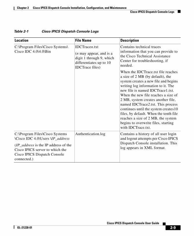
Cisco IPICS Dispatch Console LogsThe Cisco IPICS Dispatch Console maintains a variety of log files on the client PC. Table 2-1 describes these logs.
Note This table shows these logs in the C:\Program Files folder, which is the default installation folder for the Cisco IPICS Dispatch Console. If you install the Cisco IPICS Dispatch Console in another folder, the log files will be under that folder.
2-8Cisco IPICS Dispatch Console User Guide
OL-21228-01
Chapter 2 Cisco IPICS Dispatch Console Installation, Configuration, and MaintenanceCisco IPICS Dispatch Console Logs
Table 2-1 Cisco IPICS Dispatch Console Logs
Location File Name Description
C:\Program Files\Cisco Systems\ Cisco IDC 4.0\4.0\Bin
IDCTracen.txt
(n may appear, and is a digit 1 through 9, which differentiates up to 10 IDCTrace files)
Contains technical traces information that you can provide to the Cisco Technical Assistance Center for troubleshooting, if needed.
When the IDCTrace.txt file reaches a size of 2 MB (by default), the system creates a new file and begins writing log information to it. The new file is named IDCTrace1.txt. When the new file reaches a size of 2 MB, system creates another file, named IDCTrace2.txt. This process continues until the system creates10 files, by default. When the tenth file reaches a size of 2 MB, the system begins to overwrite files, starting with IDCTrace.txt.
C:\Program Files\Cisco Systems \Cisco IDC 4.0\Users \IP_address
(IP_address is the IP address of the Cisco IPICS server to which the Cisco IPICS Dispatch Console connected.)
Authentication.log Contains a history of all user login and logout attempts per Cisco IPICS Dispatch Console installation. This log appears in XML format.
2-9Cisco IPICS Dispatch Console User Guide
OL-21228-01
Chapter 2 Cisco IPICS Dispatch Console Installation, Configuration, and MaintenanceCisco IPICS Dispatch Console Logs
By default the Cisco IPICS server uploads the Authentication.log and the ChannelActivity.log files at regular intervals. You can configure this process and view these files from the Administration > Options > Client tab in the Server drawer in the Cisco IPICS Administration Console, and you can generate activity log reports from the Cisco IPICS server. For related information, see Cisco IPICS Administration Guide.
When the Cisco IPICS Dispatch Console writes to any of the log files, the application checks to make sure that available disk space exists to capture this data. If the amount of free disk space falls below a predefined level, logging activities stop and data that can no longer be written to the disk is lost. When the free disk space increases to sufficient levels, the Cisco IPICS Dispatch Console automatically resumes logging and activities.
All of the logs, except for the debug log, are based on size. The system creates a new log when the predefined limit has been reached.
The following information pertains to the Cisco IPICS Dispatch Console log files:
• The debug log (DebugLog.txt) file starts a fresh log each time you start the Cisco IPICS Dispatch Console.
• By default, the Cisco IPICS system retains one current active copy (DebugLog.txt) of the debug log.
• The Cisco IPICS system writes most error messages to the DCTracen.txt log.
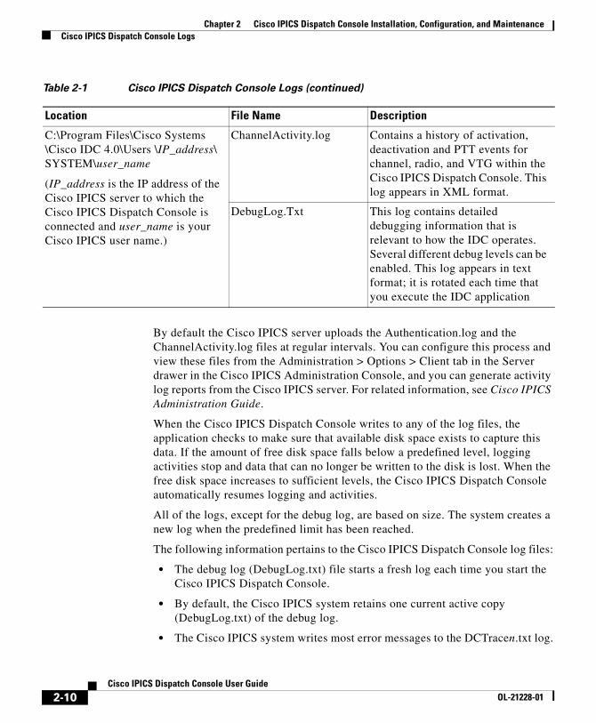
C:\Program Files\Cisco Systems \Cisco IDC 4.0\Users \IP_address\ SYSTEM\user_name
(IP_address is the IP address of the Cisco IPICS server to which the Cisco IPICS Dispatch Console is connected and user_name is your Cisco IPICS user name.)
ChannelActivity.log Contains a history of activation, deactivation and PTT events for channel, radio, and VTG within the Cisco IPICS Dispatch Console. This log appears in XML format.
DebugLog.Txt This log contains detailed debugging information that is relevant to how the IDC operates. Several different debug levels can be enabled. This log appears in text format; it is rotated each time that you execute the IDC application
Table 2-1 Cisco IPICS Dispatch Console Logs (continued)
Location File Name Description
2-10Cisco IPICS Dispatch Console User Guide
OL-21228-01
Chapter 2 Cisco IPICS Dispatch Console Installation, Configuration, and MaintenanceCisco IPICS Dispatch Console Guidelines for Use
• The server may request that a log file be uploaded from the Cisco IPICS Dispatch Console whenever a new log file is created based on file size rollover.
• The Cisco IPICS Dispatch Console timestamps all log entries in GMT format. However, it does not synchronize its clock to any central source. Therefore, Cisco recommends that the Cisco IPICS Dispatch Console client PC and the Cisco IPICS server synchronize their clocks to a central source by using Network Time Protocol (NTP).
• The Authentication.log, ChannelActivity.log, ChannelStatistics.log, and UserInterface.log appear in XML format. The Cisco IPICS server parses them and turns them into syslog format, then sends the syslog messages to the router for collection.
Cisco IPICS Dispatch Console Guidelines for UseBe aware of the following guidelines when you use the Cisco IPICS Dispatch Console:
General Guideline
• When using the push-to-talk (PTT) feature, talk in short bursts and monitor the incoming traffic indicator for a resources so that you do not talk over other Cisco IPICS users.
• To help ensure that Cisco IPICS operates efficiently, your IDC should not have more than 50 channels, radios, and VTGs in any combination powered on at any time, when no incidents are powered on. If one or more incidents are powered on, your IDC should not have more than 36 resources (channels, radios, incidents, and VTGs) in any combination powered on.
• Reboot your client PC at least once a week. This process helps ensure that Microsoft Windows operates efficiently, which in turn helps your IDC operate efficiently.
Connectivity Guidelines
• Before you launch the IDC, establish network connectivity to make sure that you have a valid IP address.
2-11Cisco IPICS Dispatch Console User Guide
OL-21228-01
Chapter 2 Cisco IPICS Dispatch Console Installation, Configuration, and MaintenanceCisco IPICS Dispatch Console Guidelines for Use
• If the Cisco VPN Client is installed on your client PC, disable the “Stateful Firewall (Always On)” option. Otherwise, SIP and multicast connections may not work correctly.
• You may need to modify your Windows firewall settings so that the IDC can send and receive the required protocols.
• Network limitations may prevent some client PCs from sending audio. In these cases, choose the remote location to connect to Cisco IPICS.
• If you use a docking station or pluggable audio devices with your PC client, exit the IDC and unplug your audio devices before you undock your PC. Otherwise, your PC may become unresponsive and require you to reboot.
• The Cisco IPICS server contains the location information to determine how the IDC should connect. For optimum connectivity and higher quality audio, use the most appropriate location for your connection type when you log in to the IDC. If you choose a location and you do not hear any voice traffic, choose a different location until you hear the audio on the channel.
• If both wired and wireless connections are active, and if you selected a location other than remote, either disable the wireless connection or make sure that the IDC uses the IP address that is assigned to the wired connection.
• To connect the IDC via a SIP-based remote connection, make sure that the IDC can establish connectivity to the RMS router. (The IDC connects to the RMS by using the IP address of the Loopback0 interface that is assigned to the RMS.) If the IDC cannot establish connectivity to the RMS, you may experience channel activation issues (such as fast busy) you they attempt to use a SIP-based remote connection.
Account Lockout and Password Expiration Guidelines
• If you incorrectly enter your IDC password multiple times and exceed the maximum number of consecutive invalid login attempts as configured in the server, your user account may be locked. In this case, the IDC does not allow you to log in to the system. A message displays to alert you to contact your system administrator to unlock your user account.
• If the number of consecutive invalid login attempts has been exceeded while you are already logged in to the IDC, the IDC allows you to continue to use the password for your current session. The IDC does not allow additional logins, however, until your user account is unlocked or your password is reset.
2-12Cisco IPICS Dispatch Console User Guide
OL-21228-01
Chapter 2 Cisco IPICS Dispatch Console Installation, Configuration, and MaintenanceCisco IPICS Dispatch Console Guidelines for Use
• If the number of consecutive invalid login attempts has been exceeded while you are logged in to the IDC via off-line mode, the IDC allows you to continue to use the password after it returns to on-line mode.The IDC does not allow additional logins, however, until your user account is unlocked or your password is reset.
• If your password has expired, the IDC does not allow you to log in to the system until after you have changed your password. To change your password, log in to the Cisco IPICS server and navigate to Home > My Profile to enter your old and new passwords.
• If your password expires while you are logged in to the IDC, the IDC allows you to continue to use the password for your current session. You must change your password before the next login.
• If your password expires while you are logged in via off line mode, the IDC allows you to continue to use the password after the IDC returns to online mode. You must change your password before the next login.
Cisco Security Agent (CSA) Guidelines
If the Cisco Security Agent (CSA) is installed on your client PC, follow these guidelines:
• If you see a CSA access permission dialog box when you try to perform an IDC operation, click Yes to grant permission and continue with that operation.
• If you see a CSA access permission dialog box when you activate a channel on the IDC, be sure to click Yes to grant permission.
• If you are prompted with a CSA access permission dialog box when you start a new version of the IDC or after a system reboot, make sure that you click Yes to allow the IDC to monitor the media device (microphone). If you allow the CSA to time out based on its default value of No after you launch the IDC, the IDC will be able to receive voice traffic but it will not be able to send voice traffic.
• If the CSA “Don’t ask me again” check box displays as an option, you may check it to instruct CSA not to prompt you again.
2-13Cisco IPICS Dispatch Console User Guide
OL-21228-01
Chapter 2 Cisco IPICS Dispatch Console Installation, Configuration, and MaintenanceOptimizing Audio for the Cisco IPICS Dispatch Console
Optimizing Audio for the Cisco IPICS Dispatch Console
After you install the Cisco IPICS Dispatch Console, check the settings for playback and recording audio devices on your client PC to ensure that you are using the preferred or default sound devices with the Cisco IPICS Dispatch Console. The following sections guide you through the audio configuration. They also provide information about properly using a USB DSP headset and microphone.
• Using a USB DSP Headset with the Cisco IPICS Dispatch Console, page 2-14
• Using a Microphone with the Cisco IPICS Dispatch Console, page 2-15
• Voice Quality Guidelines, page 2-16
Be aware that if the microphone on the client PC is busy, or if it cannot be opened by the Cisco IPICS Dispatch Console for other reasons, you can listen to active conversations but you will not be able to talk.
If you change your audio settings while you are running the Cisco IPICS Dispatch Console, you may need to exit then restart the Cisco IPICS Dispatch Console for the changes to become effective.
Using a USB DSP Headset with the Cisco IPICS Dispatch ConsoleWhen you use a USB DSP headset (that is, a headset that includes its own sound card) with the Windows operating system, Windows may configure that headset as the default speaker and microphone. Therefore, make sure that you connect the USB DSP headset to the client PC before you launch the Cisco IPICS Dispatch Console.
If you launch the Cisco IPICS Dispatch Console after you plug the headset into your PC client, the Cisco IPICS Dispatch Console may not automatically remember the audio setting for the USB DSP headset and may revert to the default Windows operating system audio settings.
2-14Cisco IPICS Dispatch Console User Guide
OL-21228-01
Chapter 2 Cisco IPICS Dispatch Console Installation, Configuration, and MaintenanceOptimizing Audio for the Cisco IPICS Dispatch Console
Note If you use the microphone on a USB headset for an extended time, your voice may become unintelligible. If this problem occurs, close the Cisco IPICS Dispatch Console and unplug the Cisco IPICS Dispatch Console headset from the client PC. Then, plug the USB headset back into the client PC and restart the Cisco IPICS Dispatch Console.
Using a Microphone with the Cisco IPICS Dispatch ConsoleCisco IPICS might be configured to use voice activity detection to squelch (silence) transmissions that contain undetectable speech. If the Cisco IPICS system cannot detect your voice when you transmit, the system may squelch the transmission. In this situation, another Cisco IPICS user may start speaking over your transmission because your voice cannot be heard and the Cisco IPICS Dispatch Console receive indicator for the listener may not display any indication of the transmission.
To avoid issues that may arise from incomplete transmissions, follow these guidelines, make sure that you use a high-quality microphone with the Cisco IPICS Dispatch Console. In addition, check the placement and settings of your microphone before you begin using the Cisco IPICS Dispatch Console.
If you encounter a situation in which you can hear other users but they cannot hear you, make sure that your microphone is not set to mute.
To check the audio recording and playback capability of a microphone on your client PC, perform the following steps to access the Windows Sound Recorder to record your voice and then listen to the recording. (Make sure that you have an audio input device connected to your PC.)
Procedure
Step 1 Choose Start > Program Files > Accessories > Entertainment > Sound Recorder.
The Sound Recorder dialog box appears.
Step 2 Click File > New.
Step 3 To begin recording, click the Record button.
This button appears in the lower right corner of the Sound Recorder dialog box.
2-15Cisco IPICS Dispatch Console User Guide
OL-21228-01
Chapter 2 Cisco IPICS Dispatch Console Installation, Configuration, and MaintenanceOptimizing Audio for the Cisco IPICS Dispatch Console
Step 4 Speak into the microphone to record your voice.
Step 5 To stop recording, click the Stop button.
Step 6 Take either of these actions:
• To listen to your recording, click the Play button. You should hear your voice as it was recorded.
• Alternatively, you can choose File > Save as and then enter a file name to save your recording file. Recorded sounds are saved as waveform (.wav) files. To play the file, choose File > Open, locate the sound file that you want to play, then, double-click the file.
Step 7 To stop playing the recording, click the Stop button.
Voice Quality GuidelinesThe following tips can help to ensure good voice quality when you use the Cisco IPICS Dispatch Console:
• Make sure that you use a high-quality headset and microphone, and check the placement and settings of both components. A high-quality and properly-configured headset can greatly enhance voice quality for both receive and transmit activity.
• The use of a PC analog sound card or the use of the analog ports on most laptop computers typically results in lower quality voice transmissions. Therefore, Cisco recommends that you do not use your PC sound card or analog ports as an alternative to a high-quality headset and microphone.
• For enhanced voice quality, make sure that you plug your USB headset or audio device into a dedicated USB port instead of a USB hub. The use of USB hubs, which multiplex data from USB devices into one data stream, can result in timing issues and can affect voice quality.
• If other Cisco IPICS users tell you that they hear a persistent or intermittent noise, such as an audible hum, when you talk, the problem may be due to defective headset hardware. In this situation, Cisco recommends that you isolate the source of the audio quality issue by replacing the defective headset with a new, high-quality headset.
2-16Cisco IPICS Dispatch Console User Guide
OL-21228-01
Chapter 2 Cisco IPICS Dispatch Console Installation, Configuration, and MaintenanceOptimizing Audio for the Cisco IPICS Dispatch Console
• Check your Windows audio settings to make sure that the volume is not set too low. If the volume is set low, increase the input gain on your microphone by sliding the bar up on the volume controls to increase the volume.
• For optimum connectivity, use the most appropriate location for your connection type when you log in to the Cisco IPICS Dispatch Console. For example, if you are using a wireless connection, choose the location that correlates to wireless connectivity for your organization. You can ensure higher quality audio by choosing the appropriate connection type.
• Be aware that a slow-speed connection, such as a digital subscriber line (DSL) or any slow wired link, may affect voice quality. If possible, try to use a high-speed connection with the Cisco IPICS Dispatch Console.
• Try to limit the use of applications that consume significant CPU and network bandwidth on a client PC when you use the Cisco IPICS Dispatch Console. If your CPU is overburdened by other programs, there may insufficient CPU cycles for the Cisco IPICS Dispatch Console to run properly. Check the CPU activity on your client PC and close any programs that do not need to be open.
2-17Cisco IPICS Dispatch Console User Guide
OL-21228-01

Chapter 2 Cisco IPICS Dispatch Console Installation, Configuration, and MaintenanceOptimizing Audio for the Cisco IPICS Dispatch Console
2-18Cisco IPICS Dispatch Console User Guide
OL-21228-01
CiscoOL-21228-01
C H A P T E R 3
Cisco IPICS Dispatch Console ReferenceThis chapter provides detailed information about the screens, windows, and options in the Cisco IPICS Dispatch Console.
The information, buttons, and tabs that are available to you in the Cisco IPICS Dispatch Console depend on your Cisco IPICS Dispatch Console user license type, your Cisco IPICS user type and the items with which you are associated in the Cisco IPICS Administration Console. For related information, see the “Cisco IPICS Dispatch Console License Types” section on page 1-6 and the “Cisco IPICS Dispatch Console Features Available by User Type” section on page 1-8.
In addition, most resources must be associated with your Cisco IPICS ops view before you can see and access them in the Cisco IPICS Dispatch Console.
This chapter includes these topics:
• Cisco IPICS Dispatch Console Main Window, page 3-2
• Menu Bar, page 3-4
• View Area, page 3-5
• Items Tabs Area, page 3-79
• Dial Pad and Channel Patch Area, page 3-86
• System Information Area, page 3-90
• Master Audio Controls Area, page 3-91
• All Talk and Patch Controls Area, page 3-92
• Regions List, page 3-94
3-1 IPICS Dispatch Console User Guide
Chapter 3 Cisco IPICS Dispatch Console ReferenceCisco IPICS Dispatch Console Main Window
• Emergency Mode, page 3-99
• Alert Message, page 3-103
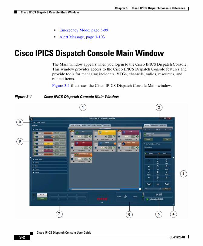
Cisco IPICS Dispatch Console Main WindowThe Main window appears when you log in to the Cisco IPICS Dispatch Console. This window provides access to the Cisco IPICS Dispatch Console features and provide tools for managing incidents, VTGs, channels, radios, resources, and related items.
Figure 3-1 illustrates the Cisco IPICS Dispatch Console Main window.
Figure 3-1 Cisco IPICS Dispatch Console Main Window
3-2Cisco IPICS Dispatch Console User Guide
OL-21228-01
Chapter 3 Cisco IPICS Dispatch Console ReferenceCisco IPICS Dispatch Console Main Window
Description Reference
1 View area—Can displays these tabs:
• Region tab—Provides information about and controls for the up to six regions that are configured in the Cisco IPICS Administration Console
• Incident Details tab—Provides features for monitoring and managing an incident
• Radio Details tab—Provides features for managing a radio
• VTG Details tab—Provides features for managing a VTG
• Event Log tab—Displays entries from the Cisco IPICS Dispatch Console event log
• Policy Execution Status tab—Provides information about the execution status of policies with which you are associated in the Cisco IPICS Administration Console
• Settings tab—Provides access to system configuration options
See the “View Area” section on page 3-5
2 Items Tabs area—Includes tabs that list VTGs, incidents, and policies, and provides quick access to detailed information about any of these items.
A user with the Cisco IPICS Dispatcher role or All role sees the VTGs, Incidents, and Policies tabs in this area. Other Cisco IPICS users see the Policies tab only.
See the “Items Tabs Area” section on page 3-79
3 Dial Pad and Channel Patch area—Lets you place up to two telephone calls and optionally patch each call to a selected resource.
This area is available only to users with the Cisco IPICS Dispatcher role or All role.
See the “Dial Pad and Channel Patch Area” section on page 3-86
4 Resize handle—Appears when the Main window is not maximized. Click and drag to resize the Main window.
—
5 System information area —Displays the system time, your Cisco IPICS user name, and the location to which the Cisco IPICS Dispatch Console is connected.
See the “System Information Area” section on page 3-90
6 Master audio controls area—Provides controls for muting and controlling the volume of the audio that is received from all powered-on resources.
See the “Master Audio Controls Area” section on page 3-91
3-3Cisco IPICS Dispatch Console User Guide
OL-21228-01
Chapter 3 Cisco IPICS Dispatch Console ReferenceMenu Bar
Menu BarThe Cisco IPICS Dispatch Console menu bar provides access to various Cisco IPICS Dispatch Console menus and options. Table 3-1 describes the items on the menu bar.
7 All Talk and Patch Controls area—Provides controls for talking to multiple resources, patching multiple resources together, or sending alert tones to multiple resources simultaneously.
See the “All Talk and Patch Controls Area” section on page 3-92
8 Regions list—Displays the regions that are configured in the Cisco IPICS Administration Console and provides controls for the resources in each region.
See the “Regions List” section on page 3-94
9 Menu bar—Provides access to various Cisco IPICS Dispatch Console menus and options.
See the “Menu Bar” section on page 3-4
Description Reference
Table 3-1 Menu Bar Items
Menu Option Description
File menu options
Close Choose this option to exit the Cisco IPICS Dispatch Console.
For related information, see the “Exiting the Cisco IPICS Dispatch Console” section on page 1-5.
View menu options
Event Log Adds the Event Log tab to the View area and displays the event log.
For more detailed information, see the “Event Log Tab” section on page 3-45.
Policy Execution Status
Adds the Policy Execution Status tab to the View area and displays information about policies with which you are associated in the Cisco IPICS Administration Console.
For more detailed information, see the “Policy Execution Status Tab” section on page 3-48.
3-4Cisco IPICS Dispatch Console User Guide
OL-21228-01
Chapter 3 Cisco IPICS Dispatch Console ReferenceView Area
View AreaThe View area displays tabs from which you can control a variety of Cisco IPICS Dispatch Console features and functions. The following sections describe these tabs, features, and functions in detail:
• Region Tab, page 3-6
• Radio Details Tab, page 3-22
• VTG Details Tab, page 3-35
• Incident Details Tab, page 3-40
• Event Log Tab, page 3-45
• Policy Execution Status Tab, page 3-48
• Settings Tab, page 3-50
Admin Console Opens the Cisco IPICS server Authentication window. From this window, you can enter your Cisco IPICS user name and password to log in to the Cisco IPICS server.
Settings Adds the Settings tab to the View area. This tab provides access to a variety of system configuration settings.
For more detailed information, see the “Settings Tab” section on page 3-50.
Help menu options
Help Provides on-screen access to the information that this User Guide contains.
About Opens a window that shows the version of the Cisco IPICS Dispatch Console that you are using.
When this window is open, you must click OK to close it before you can access other Cisco IPICS Dispatch Console functions.
Table 3-1 Menu Bar Items (continued)
Menu Option Description
3-5Cisco IPICS Dispatch Console User Guide
OL-21228-01
Chapter 3 Cisco IPICS Dispatch Console ReferenceView Area
• Adding a Resource to an Incident or VTG, page 3-60
• Viewing an Image or Video in an Incident, page 3-76
Region TabThe Region tab appears by default when you start the Cisco IPICS Dispatch Console. It provides information about and controls for resources that are configured for a region and with which you are associated. The configuration and association procedures are preformed in the Cisco IPICS Administration Console. Cisco IPICS supports up to six regions, and each one has its own Region tab.
Resources include radios, channels, VTGs, and incidents. Each resource is in either the powered on state or the powered off state. When a resource is powered on, it can be used to transmit and receive audio, and various other Cisco IPICS Dispatch Console functions become available for it. You can use the Cisco IPICS Dispatch Console to communicate with other Cisco IPICS Dispatch Console users who also have powered on the resource.
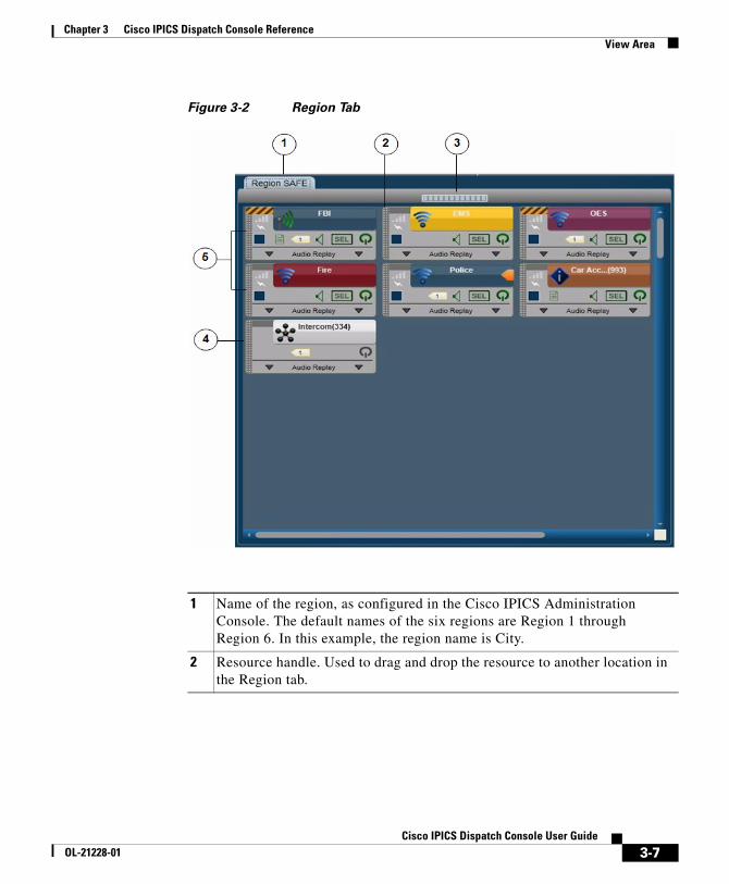
Figure 3-2 illustrates the Region tab. This example shows a region with seven resources, which have been configured in the Cisco IPICS Administration Console. In this example, six of the resources are powered on and one is powered off. In addition, this example shows resources that have been assigned custom colors in the Cisco IPICS Administration Console. You may find that using custom colors is convenient for quickly locating resources in the Cisco IPICS Dispatch Console.
3-6Cisco IPICS Dispatch Console User Guide
OL-21228-01
Chapter 3 Cisco IPICS Dispatch Console ReferenceView Area
Figure 3-2 Region Tab
1 Name of the region, as configured in the Cisco IPICS Administration Console. The default names of the six regions are Region 1 through Region 6. In this example, the region name is City.
2 Resource handle. Used to drag and drop the resource to another location in the Region tab.
3-7Cisco IPICS Dispatch Console User Guide
OL-21228-01
Chapter 3 Cisco IPICS Dispatch Console ReferenceView Area
Resources types in the Region tab are identified by icons, as follows:
• —Channel icon
• —Radio icon
• —VTG icon
• —Incident icon
A region may include more resources than you can see at once. In that case, use the scroll bars on the Region tab to display other resources.
The resources in the Region tab are arranged in a grid. You can rearrange the display by moving any resource to any empty cell in the grid. To move a resource, click and hold its handle, then drag and drop the resource to a new location. While you drag a resource, the Region tab displays the grid cells. Each cell includes two numbers, such as 3, 2, which indicate the row and column of the cell.
3 Volume indicator for incoming and outgoing audio.
4 Powered-off resource. When a resource is powered off, you can click the Power button to power it on. (You also can power on a resource by clicking its Power button in the Regions list.)
5 Powered-on resources. A powered-on resource displays several buttons and information, as described in the following sections:
• Powered-On Channels, page 3-9
• Powered-On Radios, page 3-12
• Powered-On VTGs, page 3-15
• Powered-On Incidents, page 3-17
When a resource is powered on, you can click the Power button to power it off.
Note Many of the items for a powered-on resource are duplicated in the Regions list. For more information, see the “Powered-On Resource Controls” section on page 3-96.
3-8Cisco IPICS Dispatch Console User Guide
OL-21228-01
Chapter 3 Cisco IPICS Dispatch Console ReferenceView Area
Powered-On Channels
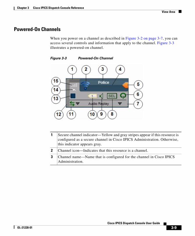
When you power on a channel as described in Figure 3-2 on page 3-7, you can access several controls and information that apply to the channel. Figure 3-3 illustrates a powered-on channel.
Figure 3-3 Powered-On Channel
1 Secure channel indicator—Yellow and gray stripes appear if this resource is configured as a secure channel in Cisco IPICS Administration. Otherwise, this indicator appears gray.
2 Channel icon—Indicates that this resource is a channel.
3 Channel name—Name that is configured for the channel in Cisco IPICS Administration.
3-9Cisco IPICS Dispatch Console User Guide
OL-21228-01
Chapter 3 Cisco IPICS Dispatch Console ReferenceView Area
4 PTT area—Click and hold anywhere in this area to talk (transmit audio) to others who are using this channel. Release when you are not talking.
This area changes to yellow when you are clicking it or when it is latched, which indicates that you have engaged the push to talk (PTT) feature. This area displays diagonal lines when this resource is configured as listen-only or your Cisco IPICS user account is configured as listen only.
In addition, when audio is received, this area may show the talker ID (either the Cisco IPICS user ID or the radio unit ID). Talker ID is not displayed if you logged in to the Cisco IPICS Dispatch Console using the Remote location, if the radio is in a location other than the location that you logged in to, or if your network or resources cannot obtain this information.
5 Latch button—Appears if the latch functionality is enabled for you and this channel as follows:
• The Allow Latch option must be enabled for your Cisco IPICS user account in Cisco IPICS Administration
• The Allow Latch option must be enabled for this channel in Cisco IPICS Administration
Click the Latch button to latch the PTT feature. Click it again to unlatch. When you latch the PTT feature, this button becomes green and the PTT area becomes yellow.
6 Power button—Click to power off a powered-on channel.
This button can appear in the following states:
• Gray—Indicates a powered-off channel.
• Green—Indicates a powered-on channel.
• Gold—Indicates a channel that is in the process of powering on. This button remains in this state if Cisco IPICS is unable to allocate system resources that are required to power on. In this case, try to power on the channel again.
3-10Cisco IPICS Dispatch Console User Guide
OL-21228-01
Chapter 3 Cisco IPICS Dispatch Console ReferenceView Area
7 Expand audio replay controls area—Click anywhere in this area to display the audio replay controls. Click this area again to hide the audio replay controls.
For more information, see the “Audio Replay Controls for Resources” section on page 3-20.
If “Emergency” flashes in red in this area, the Cisco IPICS Dispatch Console is in emergency mode. For more information, see the “Emergency Mode” section on page 3-99.
8 Audio Selection button—Choose the device group to which audio that the channel receives is sent. Options are Sel, U1, U2, and U3, which correspond to the device groups Select, Unselect1, Unselect2, and Unselect3, respectively.
For information about configuring device groups, see the “Settings Tab—Audio Connections Options” section on page 3-54.
9 Mute button—Click to locally mute (silence) incoming audio traffic from the channel. The button changes to the Unmute button . Click the Unmute button to unmute.
10 Incident icon—Appears if the channel is a participant in one or more incidents. The number in this icon designates how many incidents the channel is a participant in. Click this icon to see the list of these incidents. Click any incident in the list to display the Incident Details tab.
For more information, see the Incident Details Tab, page 40.
11 Patch icon—Appears if this channel is patched to one or more other resources.
For more information, see the “All Talk and Patch Controls Area” section on page 3-92.
12 Resource handle—Use to drag and drop the channel to another location in the Region tab.
For more information, see the “Region Tab” section on page 3-6
3-11Cisco IPICS Dispatch Console User Guide
OL-21228-01
Chapter 3 Cisco IPICS Dispatch Console ReferenceView Area
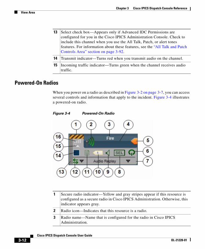
Powered-On Radios
When you power on a radio as described in Figure 3-2 on page 3-7, you can access several controls and information that apply to the incident. Figure 3-4 illustrates a powered-on radio.
Figure 3-4 Powered-On Radio
13 Select check box—Appears only if Advanced IDC Permissions are configured for you in the Cisco IPICS Administration Console. Check to include this channel when you use the All Talk, Patch, or alert tones features. For information about these features, see the “All Talk and Patch Controls Area” section on page 3-92.
14 Transmit indicator—Turns red when you transmit audio on the channel.
15 Incoming traffic indicator—Turns green when the channel receives audio traffic.
1 Secure radio indicator—Yellow and gray stripes appear if this resource is configured as a secure radio in Cisco IPICS Administration. Otherwise, this indicator appears gray.
2 Radio icon—Indicates that this resource is a radio.
3 Radio name—Name that is configured for the radio in Cisco IPICS Administration.
3-12Cisco IPICS Dispatch Console User Guide
OL-21228-01
Chapter 3 Cisco IPICS Dispatch Console ReferenceView Area
4 PTT area—Click and hold anywhere in this area to talk (transmit audio) to others who are using this radio. Release when you are not talking.
This area changes to yellow when you are clicking it or when it is latched, which indicates that you have engaged the PTT feature. This area displays diagonal lines when this resource is configured as listen-only or your Cisco IPICS user account is configured as listen only.
In addition, when audio is received, this area may show the talker ID (either the Cisco IPICS user ID or the radio unit ID). Talker ID is not displayed if you logged in to the Cisco IPICS Dispatch Console using the Remote location, if the radio is in a location other than the location that you logged in to, or if your network or resources cannot obtain this information.
5 Latch button—Appears if the latch functionality is enabled for you and this radio as follows:
• The Allow Latch option must be enabled for your Cisco IPICS user account in Cisco IPICS Administration
• The Allow Latch option must be enabled for this radio in Cisco IPICS Administration
Click the Latch button to latch the PTT feature. Click it again to unlatch. When you latch the PTT feature, this button becomes green and the PTT area becomes yellow.
6 Power button—Click to power off a powered-on radio.
This button can appear in the following states:
• Gray—Indicates a powered-off radio.
• Green—Indicates a powered-on radio.
Gold—Indicates a radio that is in the process of powering on. This button remains in this state if Cisco IPICS is unable to allocate system resources that are required to power on. In this case, try to power on the radio again.
7 Expand audio replay controls area—Click anywhere in this area to display the audio replay controls. Click this area again to hide the audio replay controls.
For more information, see the “Audio Replay Controls for Resources” section on page 3-20.
3-13Cisco IPICS Dispatch Console User Guide
OL-21228-01
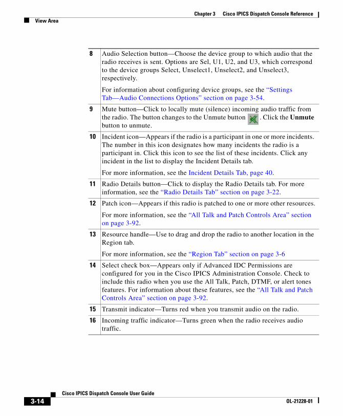
Chapter 3 Cisco IPICS Dispatch Console ReferenceView Area
8 Audio Selection button—Choose the device group to which audio that the radio receives is sent. Options are Sel, U1, U2, and U3, which correspond to the device groups Select, Unselect1, Unselect2, and Unselect3, respectively.
For information about configuring device groups, see the “Settings Tab—Audio Connections Options” section on page 3-54.
9 Mute button—Click to locally mute (silence) incoming audio traffic from the radio. The button changes to the Unmute button . Click the Unmute button to unmute.
10 Incident icon—Appears if the radio is a participant in one or more incidents. The number in this icon designates how many incidents the radio is a participant in. Click this icon to see the list of these incidents. Click any incident in the list to display the Incident Details tab.
For more information, see the Incident Details Tab, page 40.
11 Radio Details button—Click to display the Radio Details tab. For more information, see the “Radio Details Tab” section on page 3-22.
12 Patch icon—Appears if this radio is patched to one or more other resources.
For more information, see the “All Talk and Patch Controls Area” section on page 3-92.
13 Resource handle—Use to drag and drop the radio to another location in the Region tab.
For more information, see the “Region Tab” section on page 3-6
14 Select check box—Appears only if Advanced IDC Permissions are configured for you in the Cisco IPICS Administration Console. Check to include this radio when you use the All Talk, Patch, DTMF, or alert tones features. For information about these features, see the “All Talk and Patch Controls Area” section on page 3-92.
15 Transmit indicator—Turns red when you transmit audio on the radio.
16 Incoming traffic indicator—Turns green when the radio receives audio traffic.
3-14Cisco IPICS Dispatch Console User Guide
OL-21228-01
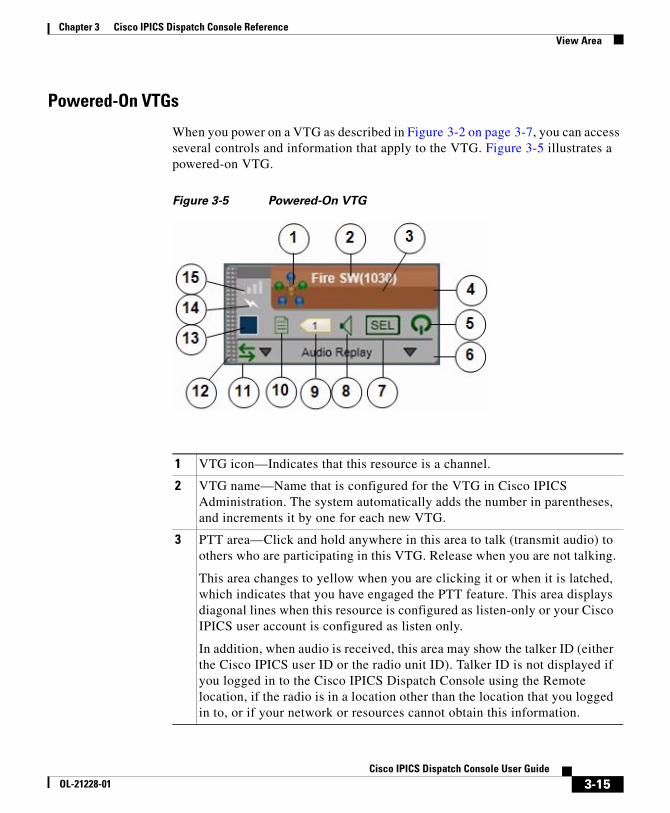
Chapter 3 Cisco IPICS Dispatch Console ReferenceView Area
Powered-On VTGs
When you power on a VTG as described in Figure 3-2 on page 3-7, you can access several controls and information that apply to the VTG. Figure 3-5 illustrates a powered-on VTG.
Figure 3-5 Powered-On VTG
1 VTG icon—Indicates that this resource is a channel.
2 VTG name—Name that is configured for the VTG in Cisco IPICS Administration. The system automatically adds the number in parentheses, and increments it by one for each new VTG.
3 PTT area—Click and hold anywhere in this area to talk (transmit audio) to others who are participating in this VTG. Release when you are not talking.
This area changes to yellow when you are clicking it or when it is latched, which indicates that you have engaged the PTT feature. This area displays diagonal lines when this resource is configured as listen-only or your Cisco IPICS user account is configured as listen only.
In addition, when audio is received, this area may show the talker ID (either the Cisco IPICS user ID or the radio unit ID). Talker ID is not displayed if you logged in to the Cisco IPICS Dispatch Console using the Remote location, if the radio is in a location other than the location that you logged in to, or if your network or resources cannot obtain this information.
3-15Cisco IPICS Dispatch Console User Guide
OL-21228-01
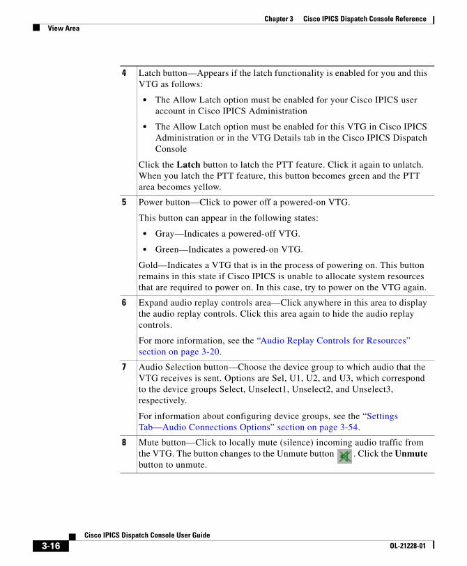
Chapter 3 Cisco IPICS Dispatch Console ReferenceView Area
4 Latch button—Appears if the latch functionality is enabled for you and this VTG as follows:
• The Allow Latch option must be enabled for your Cisco IPICS user account in Cisco IPICS Administration
• The Allow Latch option must be enabled for this VTG in Cisco IPICS Administration or in the VTG Details tab in the Cisco IPICS Dispatch Console
Click the Latch button to latch the PTT feature. Click it again to unlatch. When you latch the PTT feature, this button becomes green and the PTT area becomes yellow.
5 Power button—Click to power off a powered-on VTG.
This button can appear in the following states:
• Gray—Indicates a powered-off VTG.
• Green—Indicates a powered-on VTG.
Gold—Indicates a VTG that is in the process of powering on. This button remains in this state if Cisco IPICS is unable to allocate system resources that are required to power on. In this case, try to power on the VTG again.
6 Expand audio replay controls area—Click anywhere in this area to display the audio replay controls. Click this area again to hide the audio replay controls.
For more information, see the “Audio Replay Controls for Resources” section on page 3-20.
7 Audio Selection button—Choose the device group to which audio that the VTG receives is sent. Options are Sel, U1, U2, and U3, which correspond to the device groups Select, Unselect1, Unselect2, and Unselect3, respectively.
For information about configuring device groups, see the “Settings Tab—Audio Connections Options” section on page 3-54.
8 Mute button—Click to locally mute (silence) incoming audio traffic from the VTG. The button changes to the Unmute button . Click the Unmute button to unmute.
3-16Cisco IPICS Dispatch Console User Guide
OL-21228-01
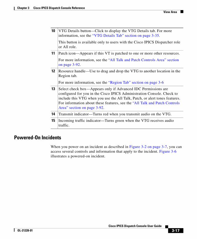
Chapter 3 Cisco IPICS Dispatch Console ReferenceView Area
Powered-On Incidents
When you power on an incident as described in Figure 3-2 on page 3-7, you can access several controls and information that apply to the incident. Figure 3-6 illustrates a powered-on incident.
10 VTG Details button—Click to display the VTG Details tab. For more information, see the “VTG Details Tab” section on page 3-35.
This button is available only to users with the Cisco IPICS Dispatcher role or All role.
11 Patch icon—Appears if this VT is patched to one or more other resources.
For more information, see the “All Talk and Patch Controls Area” section on page 3-92.
12 Resource handle—Use to drag and drop the VTG to another location in the Region tab.
For more information, see the “Region Tab” section on page 3-6
13 Select check box—Appears only if Advanced IDC Permissions are configured for you in the Cisco IPICS Administration Console. Check to include this VTG when you use the All Talk, Patch, or alert tones features. For information about these features, see the “All Talk and Patch Controls Area” section on page 3-92.
14 Transmit indicator—Turns red when you transmit audio on the VTG.
15 Incoming traffic indicator—Turns green when the VTG receives audio traffic.
3-17Cisco IPICS Dispatch Console User Guide
OL-21228-01
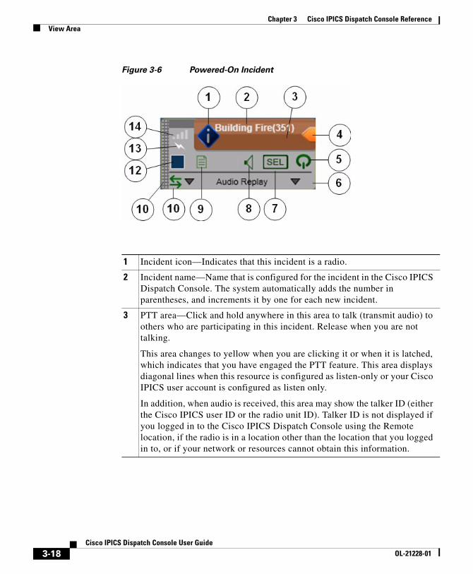
Chapter 3 Cisco IPICS Dispatch Console ReferenceView Area
Figure 3-6 Powered-On Incident
1 Incident icon—Indicates that this incident is a radio.
2 Incident name—Name that is configured for the incident in the Cisco IPICS Dispatch Console. The system automatically adds the number in parentheses, and increments it by one for each new incident.
3 PTT area—Click and hold anywhere in this area to talk (transmit audio) to others who are participating in this incident. Release when you are not talking.
This area changes to yellow when you are clicking it or when it is latched, which indicates that you have engaged the PTT feature. This area displays diagonal lines when this resource is configured as listen-only or your Cisco IPICS user account is configured as listen only.
In addition, when audio is received, this area may show the talker ID (either the Cisco IPICS user ID or the radio unit ID). Talker ID is not displayed if you logged in to the Cisco IPICS Dispatch Console using the Remote location, if the radio is in a location other than the location that you logged in to, or if your network or resources cannot obtain this information.
3-18Cisco IPICS Dispatch Console User Guide
OL-21228-01
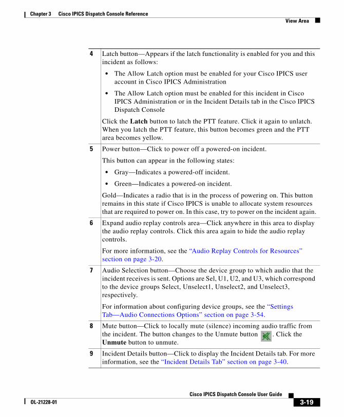
Chapter 3 Cisco IPICS Dispatch Console ReferenceView Area
4 Latch button—Appears if the latch functionality is enabled for you and this incident as follows:
• The Allow Latch option must be enabled for your Cisco IPICS user account in Cisco IPICS Administration
• The Allow Latch option must be enabled for this incident in Cisco IPICS Administration or in the Incident Details tab in the Cisco IPICS Dispatch Console
Click the Latch button to latch the PTT feature. Click it again to unlatch. When you latch the PTT feature, this button becomes green and the PTT area becomes yellow.
5 Power button—Click to power off a powered-on incident.
This button can appear in the following states:
• Gray—Indicates a powered-off incident.
• Green—Indicates a powered-on incident.
Gold—Indicates a radio that is in the process of powering on. This button remains in this state if Cisco IPICS is unable to allocate system resources that are required to power on. In this case, try to power on the incident again.
6 Expand audio replay controls area—Click anywhere in this area to display the audio replay controls. Click this area again to hide the audio replay controls.
For more information, see the “Audio Replay Controls for Resources” section on page 3-20.
7 Audio Selection button—Choose the device group to which audio that the incident receives is sent. Options are Sel, U1, U2, and U3, which correspond to the device groups Select, Unselect1, Unselect2, and Unselect3, respectively.
For information about configuring device groups, see the “Settings Tab—Audio Connections Options” section on page 3-54.
8 Mute button—Click to locally mute (silence) incoming audio traffic from the incident. The button changes to the Unmute button . Click the Unmute button to unmute.
9 Incident Details button—Click to display the Incident Details tab. For more information, see the “Incident Details Tab” section on page 3-40.
3-19Cisco IPICS Dispatch Console User Guide
OL-21228-01
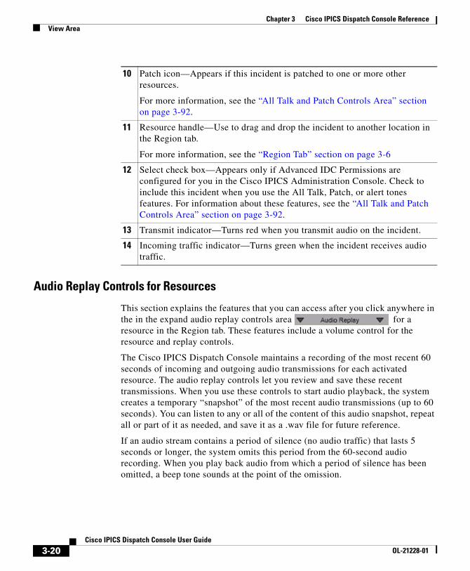
Chapter 3 Cisco IPICS Dispatch Console ReferenceView Area
Audio Replay Controls for Resources
This section explains the features that you can access after you click anywhere in the in the expand audio replay controls area for a resource in the Region tab. These features include a volume control for the resource and replay controls.
The Cisco IPICS Dispatch Console maintains a recording of the most recent 60 seconds of incoming and outgoing audio transmissions for each activated resource. The audio replay controls let you review and save these recent transmissions. When you use these controls to start audio playback, the system creates a temporary “snapshot” of the most recent audio transmissions (up to 60 seconds). You can listen to any or all of the content of this audio snapshot, repeat all or part of it as needed, and save it as a .wav file for future reference.
If an audio stream contains a period of silence (no audio traffic) that lasts 5 seconds or longer, the system omits this period from the 60-second audio recording. When you play back audio from which a period of silence has been omitted, a beep tone sounds at the point of the omission.
10 Patch icon—Appears if this incident is patched to one or more other resources.
For more information, see the “All Talk and Patch Controls Area” section on page 3-92.
11 Resource handle—Use to drag and drop the incident to another location in the Region tab.
For more information, see the “Region Tab” section on page 3-6
12 Select check box—Appears only if Advanced IDC Permissions are configured for you in the Cisco IPICS Administration Console. Check to include this incident when you use the All Talk, Patch, or alert tones features. For information about these features, see the “All Talk and Patch Controls Area” section on page 3-92.
13 Transmit indicator—Turns red when you transmit audio on the incident.
14 Incoming traffic indicator—Turns green when the incident receives audio traffic.
3-20Cisco IPICS Dispatch Console User Guide
OL-21228-01
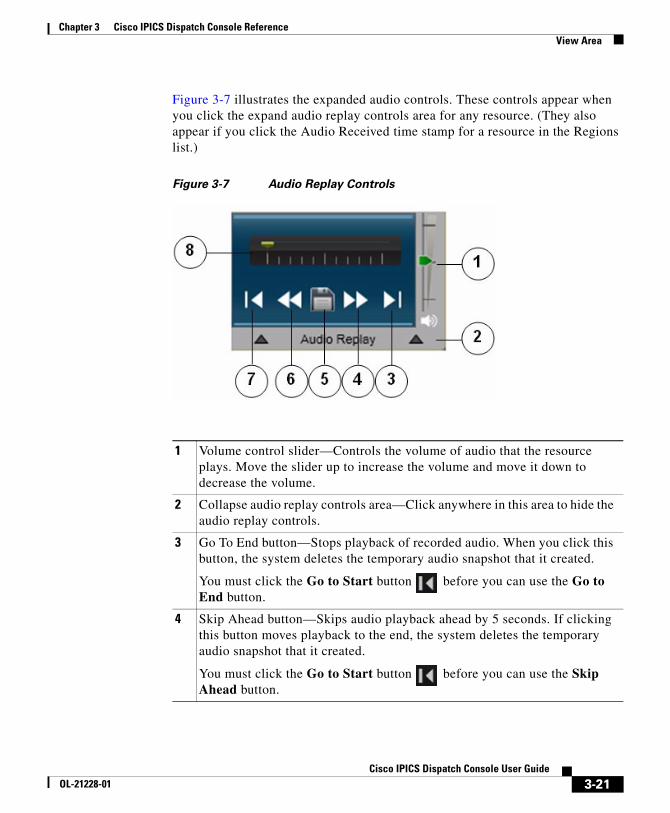
Chapter 3 Cisco IPICS Dispatch Console ReferenceView Area
Figure 3-7 illustrates the expanded audio controls. These controls appear when you click the expand audio replay controls area for any resource. (They also appear if you click the Audio Received time stamp for a resource in the Regions list.)
Figure 3-7 Audio Replay Controls
1 Volume control slider—Controls the volume of audio that the resource plays. Move the slider up to increase the volume and move it down to decrease the volume.
2 Collapse audio replay controls area—Click anywhere in this area to hide the audio replay controls.
3 Go To End button—Stops playback of recorded audio. When you click this button, the system deletes the temporary audio snapshot that it created.
You must click the Go to Start button before you can use the Go to End button.
4 Skip Ahead button—Skips audio playback ahead by 5 seconds. If clicking this button moves playback to the end, the system deletes the temporary audio snapshot that it created.
You must click the Go to Start button before you can use the Skip Ahead button.
3-21Cisco IPICS Dispatch Console User Guide
OL-21228-01
Chapter 3 Cisco IPICS Dispatch Console ReferenceView Area
Radio Details TabThe Radio Details tab provides features for managing a radio. It appears when you click the Radio Details button for a powered-on radio in the View area.
The information and options on this tab differ for tone control and serial control radios. The following sections describe the Radio Details tab for each radio type:
• Radio Details Tab for Tone Control Radios, page 3-22
• Radio Details Tab for Serial Control Radios, page 3-25
Radio Details Tab for Tone Control Radios
Figure 3-8 illustrates the Radio Details tab for tone control radios. Most settings that you make in this tab in your Cisco IPICS Dispatch Console also affect other Cisco IPICS Dispatch Consoles.
5 Save button—Saves playback as a .wav file. After clicking this button, use the pop-up window to specify a name and storage location for the .wav file, and then click OK.
You must click the Go to Start button before you can use the Save button.
6 Skip Back button—Skips audio playback back by 5 seconds. If playback is less than 5 seconds from the beginning, this button skips playback to the beginning.
You must click the Go to Start button before you can use the Skip Back button.
7 Go to Start button—Starts playback from the beginning of the audio snapshot. You must click this button before you can use the other audio control buttons or save the playback.
If you click this button while listening to audio playback, the system creates a new snapshot of the most recent 60 seconds of audio transmission and starts playback at the beginning of this snapshot.
8 Playback location indicator—Shows the relative location in the audio snapshot that you are listening to. When this indicator is at the far left, you are listening to the beginning of playback.
3-22Cisco IPICS Dispatch Console User Guide
OL-21228-01
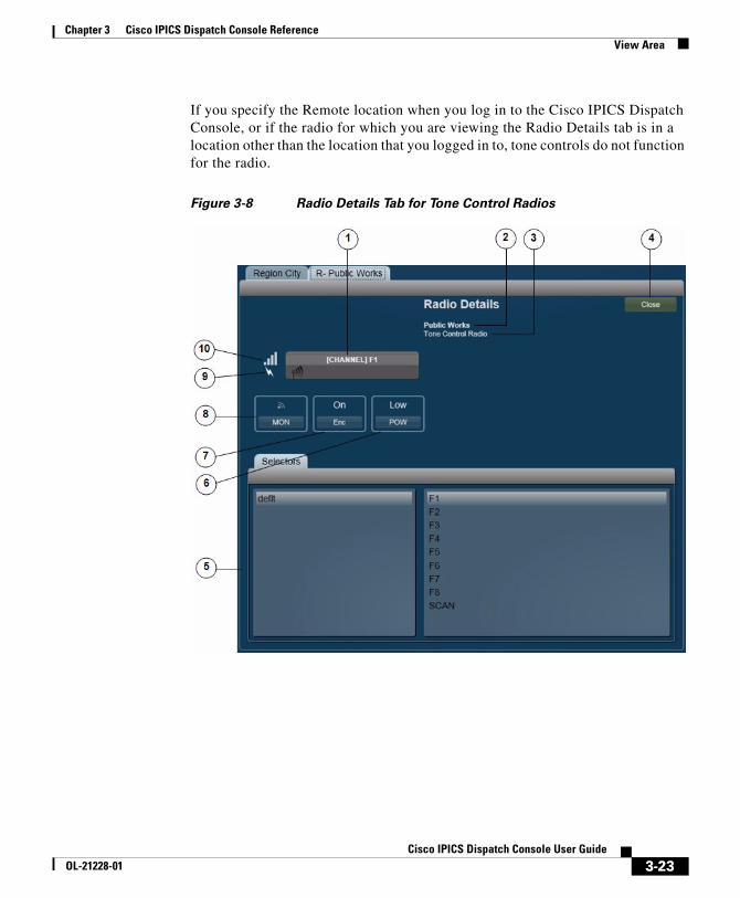
Chapter 3 Cisco IPICS Dispatch Console ReferenceView Area
If you specify the Remote location when you log in to the Cisco IPICS Dispatch Console, or if the radio for which you are viewing the Radio Details tab is in a location other than the location that you logged in to, tone controls do not function for the radio.
Figure 3-8 Radio Details Tab for Tone Control Radios
3-23Cisco IPICS Dispatch Console User Guide
OL-21228-01
Chapter 3 Cisco IPICS Dispatch Console ReferenceView Area
1 PTT button—Click and hold to talk (transmit audio) to others who are using this radio. Release when you are not talking. The text that follows [CHANNEL] indicates the radio channel that you are using to transmit and receive audio.
If you click the PTT button when the SCAN channel is selected (see row 5 in this table), scanning stops on the current channel and you can transmit audio on that channel. When you release the PTT button, the radio either resumes scanning or remains on the current channel, depending on the radio.
This button changes to yellow when you are clicking it or when it is latched, which indicates that you have engaged the push to talk (PTT) feature. This button appears with diagonal lines if this radio is configured as listen-only or if your Cisco IPICS user account is configured as listen only.
In addition, when audio is received, this area may show the talker ID (either the Cisco IPICS user ID or the radio unit ID). Talker ID is not displayed if you logged in to the Cisco IPICS Dispatch Console using the Remote location, if the radio is in a location other than the location that you logged in to, or if your network or resources cannot obtain this information.
2 Name of the radio, which has been configured in the Cisco IPICS Administration Console.
3 Indicates that this device is a tone control radio.
4 Close button—Click to exit the Radio Details tab.
5 Selectors tab—The left panel displays “dflt,” which is the name of the default group of radio channels that are available.
The right panel indicates the channels that are available to you on this radio, as configured in the Selectors tab for the radio in the Cisco IPICS Administration Console. To choose a channel, click its name in this panel. The channel name appears on the PTT button. The radio transmits and receives audio on this channel.
Choosing the channel named “SCAN” causes the radio to scan all of the channels that it has configured. When the radio locates a channel that is transmitting, it will either stop scanning or briefly stay on that channel then continue scanning. The action that it takes depends on the radio.
3-24Cisco IPICS Dispatch Console User Guide
OL-21228-01
Chapter 3 Cisco IPICS Dispatch Console ReferenceView Area
Radio Details Tab for Serial Control Radios
Figure 3-9 illustrates the Radio Details tab for serial control radios.
Most settings that you make on this tab in your Cisco IPICS Dispatch Console also affect other Cisco IPICS Dispatch Consoles. In addition settings affect the Serial Radio Control Interface (SRCI), which is described in detail in Cisco IPICS Administration Guide.
6 Power button—Click as needed to choose the transmit power level for the radio. Options are low, med, and high, or low and high, depending on the radio. These options specify low power, medium power, and high power.
This button appears only if this functionality is configured in the descriptor file for this radio, the High/Medium/Low Transmit Power control is enabled for the radio in the Cisco IPICS Administration Console, and this control is associated with your Cisco IPICS user account.
7 Encryption button—Click as needed to choose enable or disable the built-in over the air (OTA) encryption of a radio. Options are On and Off. When this option is set to On, audio that the radio transmits is encrypted by using a key in the radio.
This button appears only if this functionality is configured in the descriptor file for this radio, the Enable/Disable OTA Encryption control is enabled for the radio in the Cisco IPICS Administration Console, and this control is associated with your Cisco IPICS user account.
8 Monitor button—Click and hold to enable monitoring, which bypasses the squelch feature of the radio and lets you hear all audio that the channel receives. Release to stop monitoring.
This button appears only if this functionality is configured in the descriptor file for this radio, the Temporarily Monitor Frequencies control is enabled for the radio in the Cisco IPICS Administration Console, and this control is associated with your Cisco IPICS user account.
9 Transmit indicator—Turns red when you transmit audio on the radio.
10 Incoming traffic indicator—Turns green when the radio receives audio traffic.
3-25Cisco IPICS Dispatch Console User Guide
OL-21228-01
Chapter 3 Cisco IPICS Dispatch Console ReferenceView Area
If you specify the Remote location when you log in to the Cisco IPICS Dispatch Console, or if the radio for which you are viewing the Radio Details tab is in a location other than the location that you logged in to, the following functionality is not available:
• Radio control buttons (shown as items 10 through 15 in Figure 3-9)
• Selectors tab (shown as item 9)
• IPICS Connect tab (shown as item 10)
In this case, The Ctrl button appears instead of the radio control buttons. You can click the Ctrl button to access the Serial Radio Control Interface (SRCI), which provides access to the radio controls, selectors, and IPICS Connect functionality. For detailed information about the SRCI, see the “Managing Radios and Radio Descriptors” chapter in Cisco IPICS Administration Guide.
3-26Cisco IPICS Dispatch Console User Guide
OL-21228-01
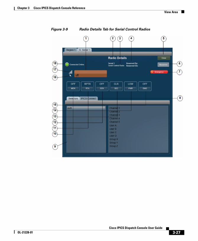
Chapter 3 Cisco IPICS Dispatch Console ReferenceView Area
Figure 3-9 Radio Details Tab for Serial Control Radios
3-27Cisco IPICS Dispatch Console User Guide
OL-21228-01
Chapter 3 Cisco IPICS Dispatch Console ReferenceView Area
1 PTT button—Click and hold to talk (transmit audio) to others who are using this radio. Release when you are not talking. Depending on your Cisco IPICS and radio deployment, this button might also include text that indicates the radio channel that you are using to transmit and receive audio.
If you click the PTT button when the SCAN function is enabled (see row12 in this table), scanning stops on the current channel and you can transmit audio on that channel. When you release the PTT button, the radio either resumes scanning, or remains on the current channel, depending on the radio.
This button changes to yellow when you are clicking it or when it is latched, which indicates that you have engaged the push to talk (PTT) feature. This button appears with diagonal lines if this radio is configured as listen-only or if your Cisco IPICS user account is configured as listen only.
In addition, when audio is received, this area may show the talker ID (either the Cisco IPICS user ID or the radio unit ID). Talker ID is not displayed if you logged in to the Cisco IPICS Dispatch Console using the Remote location, if the radio is in a location other than the location that you logged in to, or if your network or resources cannot obtain this information.
2 Name of the radio, which has been configured in the Cisco IPICS Administration Console.
3 Indicates that this device is a serial control radio.
4 Reserved information—Provides the following information, if the radio has been reserved:
• Reserved by—Shows the Cisco IPICS user name of the user, channel or VTG that reserved the radio
• Reserved on—And time that the radio was reserved
For more information, see row 6 in this table.
5 Close button—Click to exit the Radio Details tab.
3-28Cisco IPICS Dispatch Console User Guide
OL-21228-01
Chapter 3 Cisco IPICS Dispatch Console ReferenceView Area
6 Reserve/Release toggle button—Click the Reserve button to indicate to other users that you would like to use this radio. When you click this button, your Cisco IPICS user name and full name appear in the Reserved By field and the date and time that you clicked it appear in the Reserved On field. In addition, the name of the button changes to Release. In this case, other Cisco IPICS Dispatch Console and SRCI users see the Release button and they see your information in the Reserved By and Reserved On fields.
This function is provided as a courtesy only and does not block any user from controlling the radio. Any Cisco IPICS Dispatch Console or SRCI user can click the Release button, which clears the Reserved By and Reserved On information and changes the button name to Reserve.
If the radio is in an active VTG, Cisco IPICS disables the Reserve/Release button. In addition, the VTG name and the date and time that this radio was added to the VTG appear in the Reserved by field, with the date and time this radio was added to the active VTG.
7 Emergency button—Appears only when the Cisco IPICS Dispatch Console is in emergency mode. For more information, see the “Emergency Mode” section on page 3-99.
8 IPICS Connect tab—Provides access to the IPICS Connect features. For detailed information, see the “IPICS Connect” section on page 3-32.
9 Selectors tab—The left panel displays “dflt,” which is the name of the default group of radio channels that are available.
The right panel indicates the channels that are available to you on this radio, as configured in the Selectors tab for the radio in the Cisco IPICS Administration Console. To choose a channel, click its name in this panel. The channel name appears on the PTT button. The radio transmits and receives audio on this channel.
3-29Cisco IPICS Dispatch Console User Guide
OL-21228-01
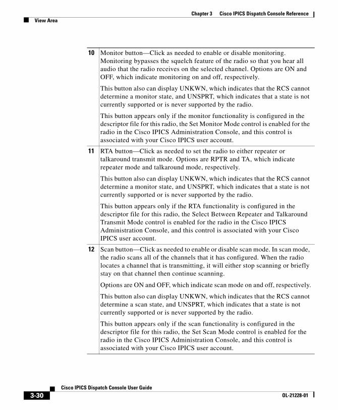
Chapter 3 Cisco IPICS Dispatch Console ReferenceView Area
10 Monitor button—Click as needed to enable or disable monitoring. Monitoring bypasses the squelch feature of the radio so that you hear all audio that the radio receives on the selected channel. Options are ON and OFF, which indicate monitoring on and off, respectively.
This button also can display UNKWN, which indicates that the RCS cannot determine a monitor state, and UNSPRT, which indicates that a state is not currently supported or is never supported by the radio.
This button appears only if the monitor functionality is configured in the descriptor file for this radio, the Set Monitor Mode control is enabled for the radio in the Cisco IPICS Administration Console, and this control is associated with your Cisco IPICS user account.
11 RTA button—Click as needed to set the radio to either repeater or talkaround transmit mode. Options are RPTR and TA, which indicate repeater mode and talkaround mode, respectively.
This button also can display UNKWN, which indicates that the RCS cannot determine a monitor state, and UNSPRT, which indicates that a state is not currently supported or is never supported by the radio.
This button appears only if the RTA functionality is configured in the descriptor file for this radio, the Select Between Repeater and Talkaround Transmit Mode control is enabled for the radio in the Cisco IPICS Administration Console, and this control is associated with your Cisco IPICS user account.
12 Scan button—Click as needed to enable or disable scan mode. In scan mode, the radio scans all of the channels that it has configured. When the radio locates a channel that is transmitting, it will either stop scanning or briefly stay on that channel then continue scanning.
Options are ON and OFF, which indicate scan mode on and off, respectively.
This button also can display UNKWN, which indicates that the RCS cannot determine a scan state, and UNSPRT, which indicates that a state is not currently supported or is never supported by the radio.
This button appears only if the scan functionality is configured in the descriptor file for this radio, the Set Scan Mode control is enabled for the radio in the Cisco IPICS Administration Console, and this control is associated with your Cisco IPICS user account.
3-30Cisco IPICS Dispatch Console User Guide
OL-21228-01
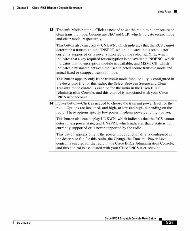
Chapter 3 Cisco IPICS Dispatch Console ReferenceView Area
13 Transmit Mode button—Click as needed to set the radio to either secure or clear transmit mode. Options are SEC and CLR, which indicate secure mode and clear mode, respectively.
This button also can display UNKWN, which indicates that the RCS cannot determine a transmit state; UNSPRT, which indicates that a state is not currently supported or is never supported by the radio; KEYFL, which indicates that a key required for encryption is not available; NOENC, which indicates that no encryption module is available; and MSMTCH, which indicates a mismatch between the user selected secure transmit mode and actual fixed or strapped transmit mode.
This button appears only if the transmit mode functionality is configured in the descriptor file for this radio, the Select Between Secure and Clear Transmit mode control is enabled for the radio in the Cisco IPICS Administration Console, and this control is associated with your Cisco IPICS user account.
14 Power button—Click as needed to choose the transmit power level for the radio. Options are low, med, and high, or low and high, depending on the radio. These options specify low power, medium power, and high power.
This button also can display UNKWN, which indicates that the RCS cannot determine a power state, and UNSPRT, which indicates that a state is not currently supported or is never supported by the radio.
This button appears only if the power mode functionality is configured in the descriptor file for this radio, the Change the Transmit Power Level control is enabled for the radio in the Cisco IPICS Administration Console, and this control is associated with your Cisco IPICS user account.
3-31Cisco IPICS Dispatch Console User Guide
OL-21228-01
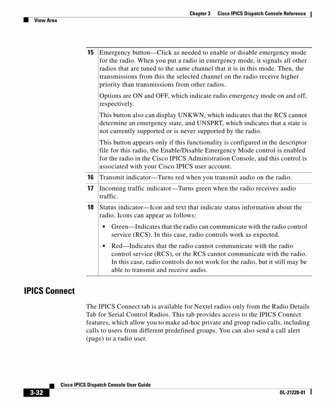
Chapter 3 Cisco IPICS Dispatch Console ReferenceView Area
IPICS Connect
The IPICS Connect tab is available for Nextel radios only from the Radio Details Tab for Serial Control Radios. This tab provides access to the IPICS Connect features, which allow you to make ad-hoc private and group radio calls, including calls to users from different predefined groups. You can also send a call alert (page) to a radio user.
15 Emergency button—Click as needed to enable or disable emergency mode for the radio. When you put a radio in emergency mode, it signals all other radios that are tuned to the same channel that it is in this mode. Then, the transmissions from this the selected channel on the radio receive higher priority than transmissions from other radios.
Options are ON and OFF, which indicate radio emergency mode on and off, respectively.
This button also can display UNKWN, which indicates that the RCS cannot determine an emergency state, and UNSPRT, which indicates that a state is not currently supported or is never supported by the radio.
This button appears only if this functionality is configured in the descriptor file for this radio, the Enable/Disable Emergency Mode control is enabled for the radio in the Cisco IPICS Administration Console, and this control is associated with your Cisco IPICS user account.
16 Transmit indicator—Turns red when you transmit audio on the radio.
17 Incoming traffic indicator—Turns green when the radio receives audio traffic.
18 Status indicator—Icon and text that indicate status information about the radio. Icons can appear as follows:
• Green—Indicates that the radio can communicate with the radio control service (RCS). In this case, radio controls work as expected.
• Red—Indicates that the radio cannot communicate with the radio control service (RCS), or the RCS cannot communicate with the radio. In this case, radio controls do not work for the radio, but it still may be able to transmit and receive audio.
3-32Cisco IPICS Dispatch Console User Guide
OL-21228-01
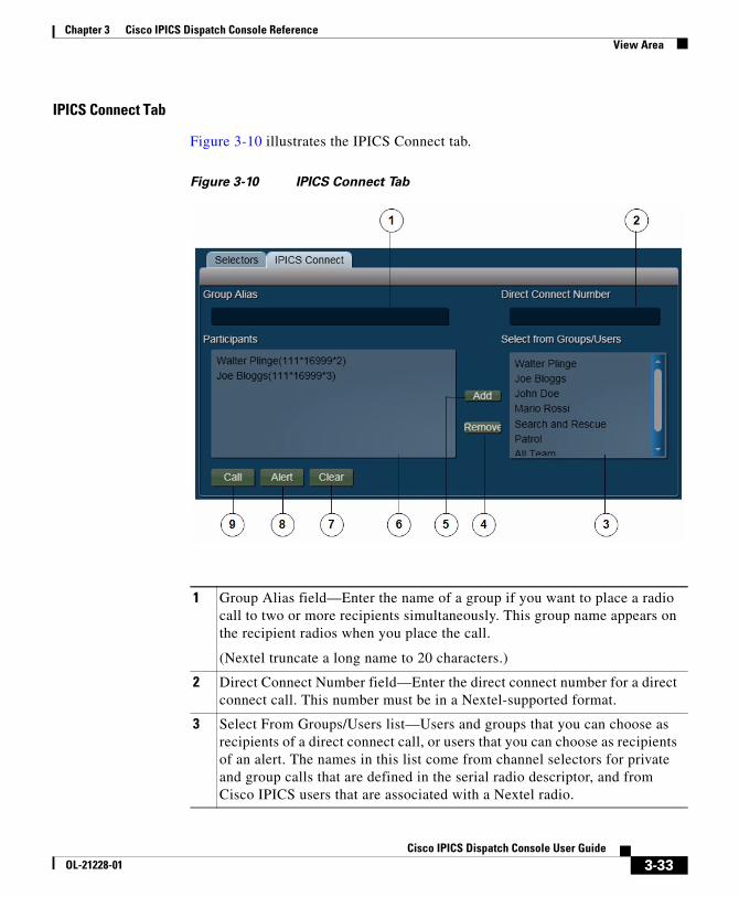
Chapter 3 Cisco IPICS Dispatch Console ReferenceView Area
IPICS Connect Tab
Figure 3-10 illustrates the IPICS Connect tab.
Figure 3-10 IPICS Connect Tab
1 Group Alias field—Enter the name of a group if you want to place a radio call to two or more recipients simultaneously. This group name appears on the recipient radios when you place the call.
(Nextel truncate a long name to 20 characters.)
2 Direct Connect Number field—Enter the direct connect number for a direct connect call. This number must be in a Nextel-supported format.
3 Select From Groups/Users list—Users and groups that you can choose as recipients of a direct connect call, or users that you can choose as recipients of an alert. The names in this list come from channel selectors for private and group calls that are defined in the serial radio descriptor, and from Cisco IPICS users that are associated with a Nextel radio.
3-33Cisco IPICS Dispatch Console User Guide
OL-21228-01
Chapter 3 Cisco IPICS Dispatch Console ReferenceView Area
Using the IPICS Connect Tab
To place a call from the IPICS Connect tab to a direct connect number or to a single user, follow these steps:
Procedure
Step 1 Take either of these actions:
• Enter the direct connect number to call in the Direct Connector Number field and then click Add to move the number to the Participants list. The number must be in a Nextel-supported format.
• Click the name of a user to call in the Select From Groups/Users list and then click Add to move the name to the Participants list.
Step 2 Click Call to place the call to the selected number or user.
To place a group call from the IPICS Connect tab, follow these steps:
Procedure
Step 1 Enter a group name (from 1 to 20 characters) in the Group Alias field.
4 Remove button—Click to remove a highlighted item from the Participants list.
5 Add button—Click to add a highlighted item from the Select From Groups/Users list to the Participants list.
6 Participants list—Users and groups to which the direct connect call or alert is placed.
7 Clear button—Click to remove all items from the Select From Groups/Users list to the Participants list.
8 Alert button—Click to place an alert to the selected users, groups, or numbers in the Participants list.
9 Call button—Click to place a direct connect call to the selected users, groups, or numbers in the Participants list.
3-34Cisco IPICS Dispatch Console User Guide
OL-21228-01
Chapter 3 Cisco IPICS Dispatch Console ReferenceView Area
Step 2 Take either or both of these actions:
• Enter a direct connect number in the Direct Connector Number field and then click the Add button to move the number to the Participants list.
• Click a name in the Groups/Users list and then click the Add button to move the item to the Participants list.
Repeat this step as needed to specify up to 20 items in the Participants list.
Step 3 Click Call to initiate the group call.
To send an alert (page) from the IPICS Connect tab, follow these steps:
Procedure
Step 1 Take either of these actions:
• Enter the direct connect number to page in the Direct Connect Number field and then click add to move the number to the Participants list.
• Click a name of the user to page in the Select From Groups/Users list and then click Add to move the name to the Participants list.
Step 2 Click Alert to place the alert to the selected direct connect number or user.
You can send an alert to only one participant at a time.
VTG Details TabThe VTG Details tab provides features that allow you to manage VTGs. It is available only for users with the Cisco IPICS Dispatcher role or All roles.
This tab appears when you take any of these actions:
• Click the VTG Details button for a powered-on VTG in the View area.
• Double-click a VTG name in the VTGs tab in the Items Tabs area
• Highlight a VTG in the VTGs tab and then click the Details button at the bottom of the VTGs tab (requires a Cisco IPICS Dispatch Console Platinum user license)
3-35Cisco IPICS Dispatch Console User Guide
OL-21228-01
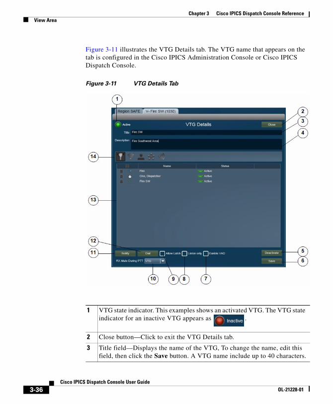
Chapter 3 Cisco IPICS Dispatch Console ReferenceView Area
Figure 3-11 illustrates the VTG Details tab. The VTG name that appears on the tab is configured in the Cisco IPICS Administration Console or Cisco IPICS Dispatch Console.
Figure 3-11 VTG Details Tab
1 VTG state indicator. This examples shows an activated VTG. The VTG state indicator for an inactive VTG appears as .
2 Close button—Click to exit the VTG Details tab.
3 Title field—Displays the name of the VTG, To change the name, edit this field, then click the Save button. A VTG name include up to 40 characters.
3-36Cisco IPICS Dispatch Console User Guide
OL-21228-01
Chapter 3 Cisco IPICS Dispatch Console ReferenceView Area
4 Description field—Displays a description of the VTG, To change the description, edit this field, then click the Save button.
5 Deactivate VTG button (available only when a VTG is activated)—Click to deactivate a VTG. When a VTG is deactivated, this button appears as Activate VTG. Click the Activate VTG button to activate the VTG.
When you activate a VTG, Cisco IPICS commits global resources, such as a multicast address and any necessary dial-in peers, so that the participants in the VTG can communicate with each other.
6 Save button—Click to saves changes that you make in the Title or Description fields, or to the Allow Latch, Listen Only, Enable VAD, or RX Mute during PTT settings.
7 Enable VAD selector—Use to enable or disable Voice Activity Detection (VAD) for the VTG. VAD can be useful when a user latches a resource and that resource sends unintended audio.
VAD is disabled by default. An X indicates that VAD is enabled.
8 Listen Only selector—Use to control whether users can use the PTT button for this VTG. When option is selected, users cannot use the PTT button for this VTG so then can hear, but not transmit, audio.
Listen Only is disabled by default. An X indicates that Listen Only is enabled.
9 Allow Latch selector—Use to enable or disable latch functionality for the VTG.
Allow Latch is disabled by default. An X indicates that Allow Latch is enabled.
10 RX Mute during PTT drop-down list—Provides the following options for muting incoming traffic when you user the PTT button for this VTG:
• VTG—Mutes incoming traffic on this VTG only
• All—Mutes incoming traffic on all resources in the IDC
• None—Incoming traffic is not muted for this VTG or any other resource
3-37Cisco IPICS Dispatch Console User Guide
OL-21228-01
Chapter 3 Cisco IPICS Dispatch Console ReferenceView Area
11 Notify button—Click to initiate the notification action that is configured for the VTG in the Cisco IPICS Administration Console. The notification action affects the users that you choose in the Resource List (see row 13 in this table). A pop-up window confirms the action. Click OK to exit the pop-up window.
12 Dial button—Click to initiate the dial-out action that is configured for the VTG in the Cisco IPICS Administration Console. The dial-out action affects the users that you choose in the Resource List (see row 13 in this table). A pop-up window confirms the action. Click OK to exit the pop-up window.
3-38Cisco IPICS Dispatch Console User Guide
OL-21228-01
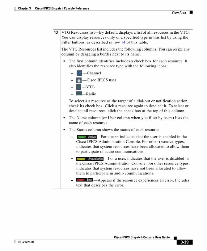
Chapter 3 Cisco IPICS Dispatch Console ReferenceView Area
13 VTG Resources list—By default, displays a list of all resources in the VTG. You can display resources only of a specified type in this list by using the Filter buttons, as described in row 14 of this table.
The VTG Resources list includes the following columns. You can resize any column by dragging a border next to its name.
• The first column identifies includes a check box for each resource. It also identifies the resource type with the following icons:
– —Channel
– —Cisco IPICS user
– —VTG
– —Radio
To select a a resource as the target of a dial-out or notification action, check its check box. Click a resource again to deselect it. To select or deselect all resources, click the check box at the top of this column.
• The Name column (or User column when you filter by users) lists the name of each resource
• The Status column shows the status of each resource:
– —For a user, indicates that the user is enabled in the Cisco IPICS Administration Console. For other resource types, indicates that system resources have been allocated to allow them to participate in audio communications.
– —For a user, indicates that the user is disabled in the Cisco IPICS Administration Console. For other resource types, indicates that system resources have not been allocated to allow them to participate in audio communications.
– —Appears if the resource experiences an error. Includes text that describes the error.
3-39Cisco IPICS Dispatch Console User Guide
OL-21228-01
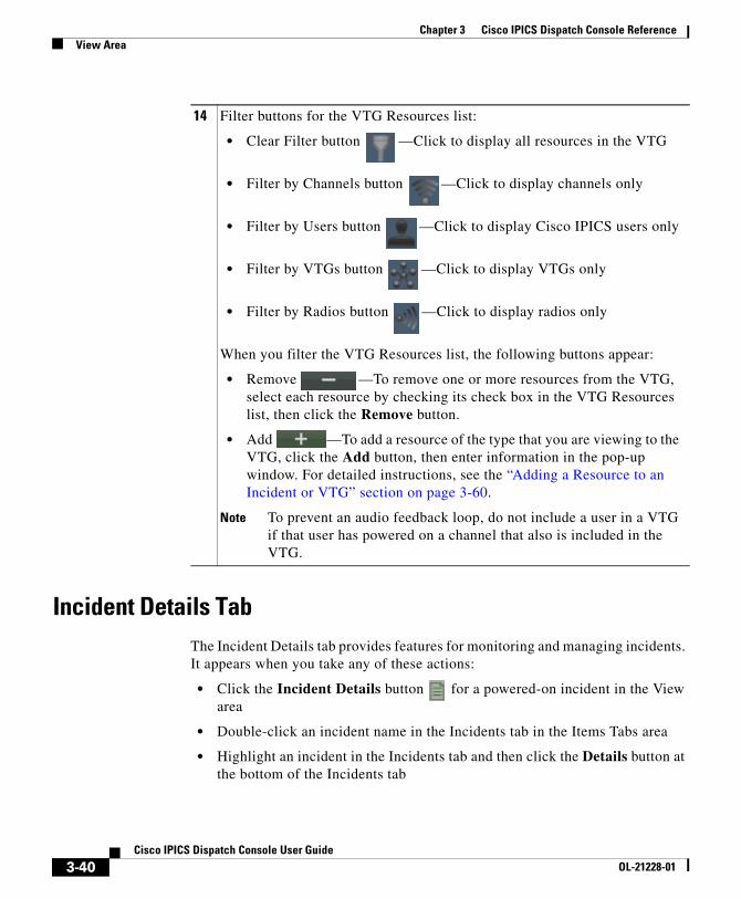
Chapter 3 Cisco IPICS Dispatch Console ReferenceView Area
Incident Details TabThe Incident Details tab provides features for monitoring and managing incidents. It appears when you take any of these actions:
• Click the Incident Details button for a powered-on incident in the View area
• Double-click an incident name in the Incidents tab in the Items Tabs area
• Highlight an incident in the Incidents tab and then click the Details button at the bottom of the Incidents tab
14 Filter buttons for the VTG Resources list:
• Clear Filter button —Click to display all resources in the VTG
• Filter by Channels button —Click to display channels only
• Filter by Users button —Click to display Cisco IPICS users only
• Filter by VTGs button —Click to display VTGs only
• Filter by Radios button —Click to display radios only
When you filter the VTG Resources list, the following buttons appear:
• Remove —To remove one or more resources from the VTG, select each resource by checking its check box in the VTG Resources list, then click the Remove button.
• Add —To add a resource of the type that you are viewing to the VTG, click the Add button, then enter information in the pop-up window. For detailed instructions, see the “Adding a Resource to an Incident or VTG” section on page 3-60.
Note To prevent an audio feedback loop, do not include a user in a VTG if that user has powered on a channel that also is included in the VTG.
3-40Cisco IPICS Dispatch Console User Guide
OL-21228-01
Chapter 3 Cisco IPICS Dispatch Console ReferenceView Area
• Click the Incident icon for a powered-on channel, radio, or VTG, then double-click an incident in the incident list that appears
The Incident Details tab also lets you activate an incident VTG, which enables the participants in an incident to communicate with each other. An incident VTG is a convenient way to quickly establish communication between incident participants. It is not a standard Cisco IPICS VTG and does not appear as a VTG in the Items Tabs area or in the Cisco IPICS Administration Console.
Note • A user with a Cisco IPICS Dispatch Console Platinum user license and the Cisco IPICS Dispatcher role or All role can access the Incident Details tab for any incident by clicking the incident name in the Incident tab. For more information, see the “Incidents Tab” section on page 3-81.
• A user with the Cisco IPICS Dispatcher role or All role can use all features in the Incident Details tab. Other users can add journals, images, and videos only.
Figure 3-12 illustrates the Incident Details tab. The incident name that appears on the tab is the name that is in the Cisco IPICS Dispatch Console.
3-41Cisco IPICS Dispatch Console User Guide
OL-21228-01
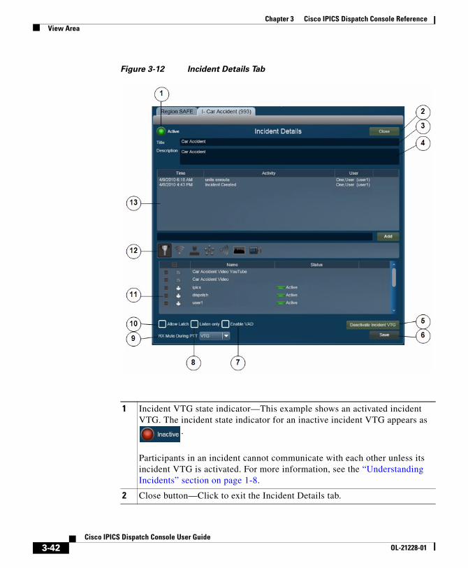
Chapter 3 Cisco IPICS Dispatch Console ReferenceView Area
Figure 3-12 Incident Details Tab
1 Incident VTG state indicator—This example shows an activated incident VTG. The incident state indicator for an inactive incident VTG appears as
.
Participants in an incident cannot communicate with each other unless its incident VTG is activated. For more information, see the “Understanding Incidents” section on page 1-8.
2 Close button—Click to exit the Incident Details tab.
3-42Cisco IPICS Dispatch Console User Guide
OL-21228-01
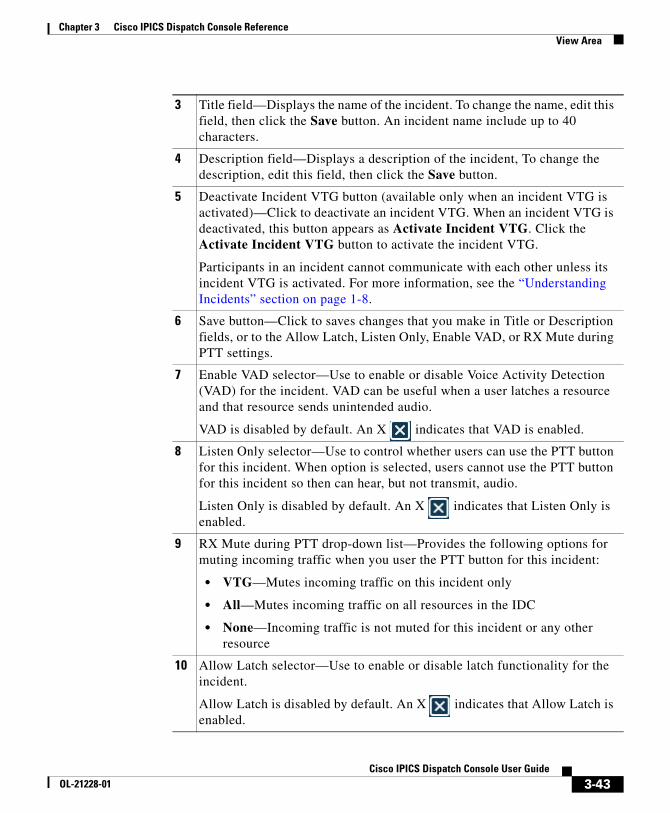
Chapter 3 Cisco IPICS Dispatch Console ReferenceView Area
3 Title field—Displays the name of the incident. To change the name, edit this field, then click the Save button. An incident name include up to 40 characters.
4 Description field—Displays a description of the incident, To change the description, edit this field, then click the Save button.
5 Deactivate Incident VTG button (available only when an incident VTG is activated)—Click to deactivate an incident VTG. When an incident VTG is deactivated, this button appears as Activate Incident VTG. Click the Activate Incident VTG button to activate the incident VTG.
Participants in an incident cannot communicate with each other unless its incident VTG is activated. For more information, see the “Understanding Incidents” section on page 1-8.
6 Save button—Click to saves changes that you make in Title or Description fields, or to the Allow Latch, Listen Only, Enable VAD, or RX Mute during PTT settings.
7 Enable VAD selector—Use to enable or disable Voice Activity Detection (VAD) for the incident. VAD can be useful when a user latches a resource and that resource sends unintended audio.
VAD is disabled by default. An X indicates that VAD is enabled.
8 Listen Only selector—Use to control whether users can use the PTT button for this incident. When option is selected, users cannot use the PTT button for this incident so then can hear, but not transmit, audio.
Listen Only is disabled by default. An X indicates that Listen Only is enabled.
9 RX Mute during PTT drop-down list—Provides the following options for muting incoming traffic when you user the PTT button for this incident:
• VTG—Mutes incoming traffic on this incident only
• All—Mutes incoming traffic on all resources in the IDC
• None—Incoming traffic is not muted for this incident or any other resource
10 Allow Latch selector—Use to enable or disable latch functionality for the incident.
Allow Latch is disabled by default. An X indicates that Allow Latch is enabled.
3-43Cisco IPICS Dispatch Console User Guide
OL-21228-01
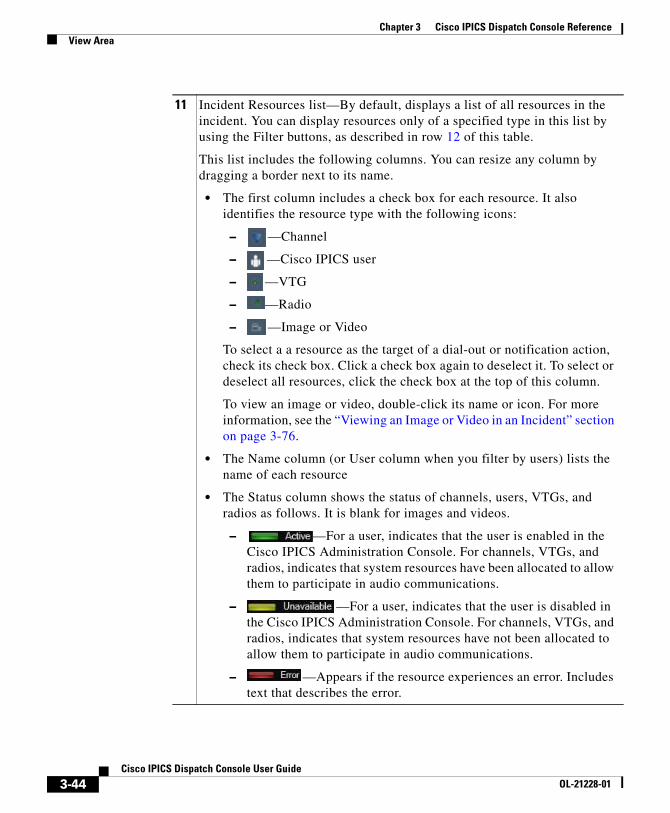
Chapter 3 Cisco IPICS Dispatch Console ReferenceView Area
11 Incident Resources list—By default, displays a list of all resources in the incident. You can display resources only of a specified type in this list by using the Filter buttons, as described in row 12 of this table.
This list includes the following columns. You can resize any column by dragging a border next to its name.
• The first column includes a check box for each resource. It also identifies the resource type with the following icons:
– —Channel
– —Cisco IPICS user
– —VTG
– —Radio
– —Image or Video
To select a a resource as the target of a dial-out or notification action, check its check box. Click a check box again to deselect it. To select or deselect all resources, click the check box at the top of this column.
To view an image or video, double-click its name or icon. For more information, see the “Viewing an Image or Video in an Incident” section on page 3-76.
• The Name column (or User column when you filter by users) lists the name of each resource
• The Status column shows the status of channels, users, VTGs, and radios as follows. It is blank for images and videos.
– —For a user, indicates that the user is enabled in the Cisco IPICS Administration Console. For channels, VTGs, and radios, indicates that system resources have been allocated to allow them to participate in audio communications.
– —For a user, indicates that the user is disabled in the Cisco IPICS Administration Console. For channels, VTGs, and radios, indicates that system resources have not been allocated to allow them to participate in audio communications.
– —Appears if the resource experiences an error. Includes text that describes the error.
3-44Cisco IPICS Dispatch Console User Guide
OL-21228-01
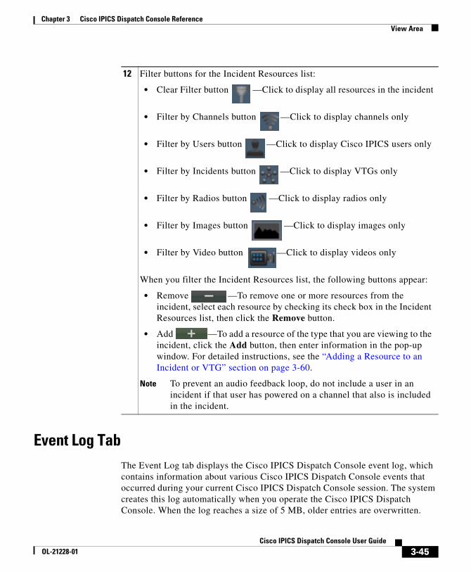
Chapter 3 Cisco IPICS Dispatch Console ReferenceView Area
Event Log TabThe Event Log tab displays the Cisco IPICS Dispatch Console event log, which contains information about various Cisco IPICS Dispatch Console events that occurred during your current Cisco IPICS Dispatch Console session. The system creates this log automatically when you operate the Cisco IPICS Dispatch Console. When the log reaches a size of 5 MB, older entries are overwritten.
12 Filter buttons for the Incident Resources list:
• Clear Filter button —Click to display all resources in the incident
• Filter by Channels button —Click to display channels only
• Filter by Users button —Click to display Cisco IPICS users only
• Filter by Incidents button —Click to display VTGs only
• Filter by Radios button —Click to display radios only
• Filter by Images button —Click to display images only
• Filter by Video button —Click to display videos only
When you filter the Incident Resources list, the following buttons appear:
• Remove —To remove one or more resources from the incident, select each resource by checking its check box in the Incident Resources list, then click the Remove button.
• Add —To add a resource of the type that you are viewing to the incident, click the Add button, then enter information in the pop-up window. For detailed instructions, see the “Adding a Resource to an Incident or VTG” section on page 3-60.
Note To prevent an audio feedback loop, do not include a user in an incident if that user has powered on a channel that also is included in the incident.
3-45Cisco IPICS Dispatch Console User Guide
OL-21228-01
Chapter 3 Cisco IPICS Dispatch Console ReferenceView Area
The Cisco IPICS Dispatch Console also stores information in other log files. For more information, see the “Cisco IPICS Dispatch Console Logs” section on page 2-8.
The Event Log tab displays each log entry on one line. Each entry includes information in a subject, name, priority, type, and timestamp column. By default, entries appear in the order that events occurred, with the most recent event first.
You can change the display by sorting entries in ascending or descending order by name, priority, type, or timestamp. You also can resize any column by dragging a border next to its name.
To display the Event Log tab, choose View > Event Log.
Figure 3-13 illustrates the Event Log tab.
3-46Cisco IPICS Dispatch Console User Guide
OL-21228-01
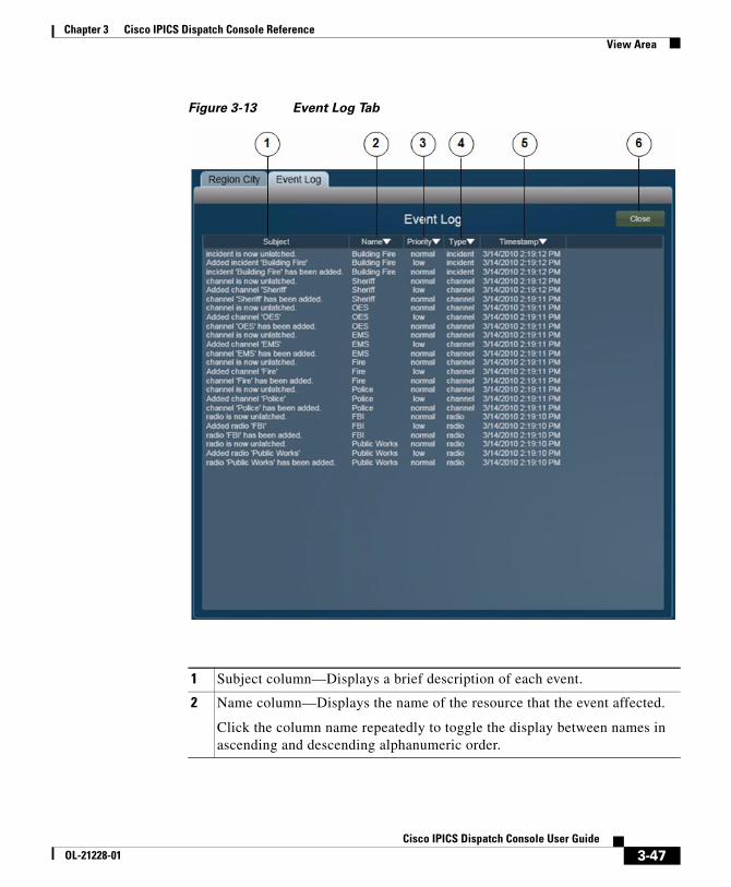
Chapter 3 Cisco IPICS Dispatch Console ReferenceView Area
Figure 3-13 Event Log Tab
1 Subject column—Displays a brief description of each event.
2 Name column—Displays the name of the resource that the event affected.
Click the column name repeatedly to toggle the display between names in ascending and descending alphanumeric order.
3-47Cisco IPICS Dispatch Console User Guide
OL-21228-01
Chapter 3 Cisco IPICS Dispatch Console ReferenceView Area
Policy Execution Status TabThe Policy Execution Status tab displays information about policies that have executed during your current Cisco IPICS Dispatch Console session.
A user with the Cisco IPICS Dispatcher role or All role can see information about all policies. Other users can see information only about policies with which they are associated.
By default, the Policy Execution Status tab displays a collapsed view of each policy, which shows the policy name and its status (“SUCCESSFUL” if it executed successfully or “FAILED” if it did not). You can expand any policy to see also the actions that it performed status of each action.
To display the Policy Execution Status tab, choose View > Policy Status.
Figure 3-14 illustrates the Policy Execution Status tab. This example shows one collapsed policy and one expanded policy.
3 Priority column—Displays the priority the event. This value provides information about the relative importance of an event.
Click the column name repeatedly to toggle the display between highest priority first and lowest priority first.
4 Type column—Displays the type of the resource that the event affected.
Click the column name repeatedly to toggle the display order between types in ascending and descending alphabetical order.
5 Timestamp column—Displays the date and time that the event occurred.
Click the column name repeatedly to toggle the display order between most current entry first and most current entry last.
6 Close button—Click to exit the Event Log tab.
3-48Cisco IPICS Dispatch Console User Guide
OL-21228-01
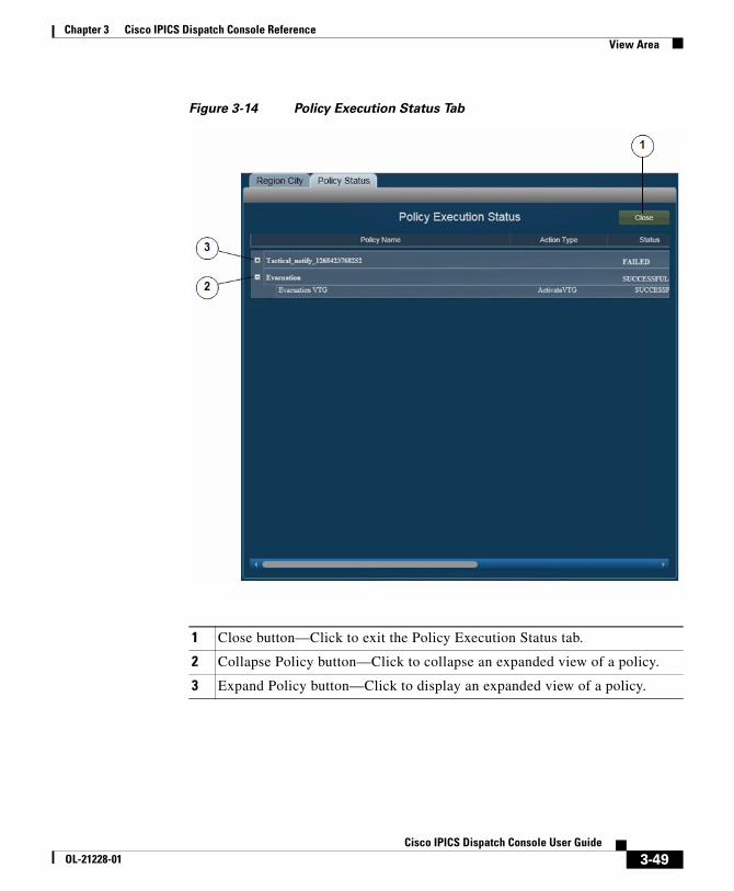
Chapter 3 Cisco IPICS Dispatch Console ReferenceView Area
Figure 3-14 Policy Execution Status Tab
1 Close button—Click to exit the Policy Execution Status tab.
2 Collapse Policy button—Click to collapse an expanded view of a policy.
3 Expand Policy button—Click to display an expanded view of a policy.
3-49Cisco IPICS Dispatch Console User Guide
OL-21228-01
Chapter 3 Cisco IPICS Dispatch Console ReferenceView Area
Settings TabThe Settings tab provide options for configuring several Cisco IPICS Dispatch Console functions. These options include:
• Themes—Defines whether the Cisco IPICS Dispatch Console user interface appears in the light or dark color theme, and provides options that affect various items
• Audio connections—Provides options for assigning audio devices to groups, which can then be used by resources
• Key assignments—Let you assign PTT functions to hotkeys
• Network settings—Lets you choose a network interface card (NIC) on which the Cisco IPICS Dispatch Console sends and receives audio, if your client PC has more than one NIC
To display the Settings tab, choose View > Settings.
Figure 3-15 illustrates the Settings tab. This example shows the Themes options, which appear by default when you choose this tab.
3-50Cisco IPICS Dispatch Console User Guide
OL-21228-01
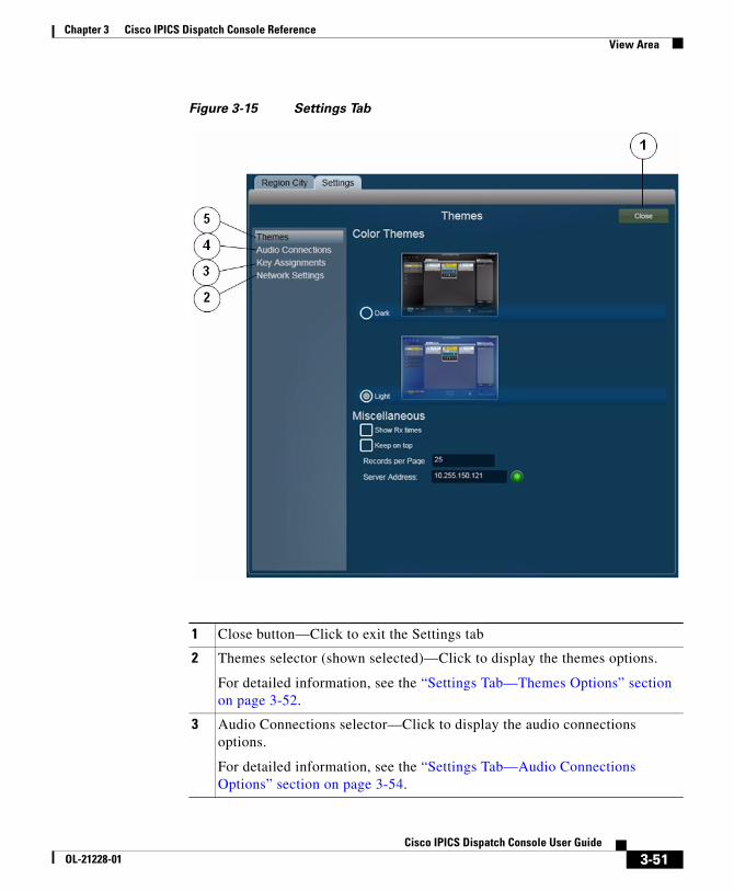
Chapter 3 Cisco IPICS Dispatch Console ReferenceView Area
Figure 3-15 Settings Tab
1 Close button—Click to exit the Settings tab
2 Themes selector (shown selected)—Click to display the themes options.
For detailed information, see the “Settings Tab—Themes Options” section on page 3-52.
3 Audio Connections selector—Click to display the audio connections options.
For detailed information, see the “Settings Tab—Audio Connections Options” section on page 3-54.
3-51Cisco IPICS Dispatch Console User Guide
OL-21228-01
Chapter 3 Cisco IPICS Dispatch Console ReferenceView Area
Settings Tab—Themes Options
The themes options in the Settings tab let you designate whether the Cisco IPICS Dispatch Console user interface appears in the light or dark color theme, and configure various other items.
Figure 3-16 illustrates the themes options in the Settings tab.
4 Key Assignments selector—Click to display the key assignment options.
For detailed information, see the “Settings Tab—Key Assignments Options” section on page 3-57.
5 Network Settings selector—Click to display the network settings options.
For detailed information, see the “Settings Tab—Network Settings Options” section on page 3-59.
3-52Cisco IPICS Dispatch Console User Guide
OL-21228-01
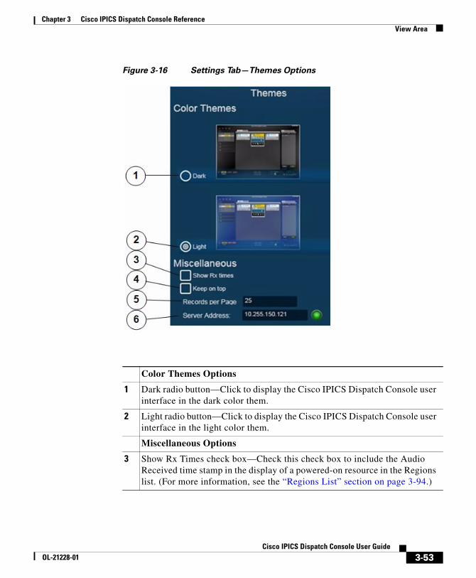
Chapter 3 Cisco IPICS Dispatch Console ReferenceView Area
Figure 3-16 Settings Tab—Themes Options
Color Themes Options
1 Dark radio button—Click to display the Cisco IPICS Dispatch Console user interface in the dark color them.
2 Light radio button—Click to display the Cisco IPICS Dispatch Console user interface in the light color them.
Miscellaneous Options
3 Show Rx Times check box—Check this check box to include the Audio Received time stamp in the display of a powered-on resource in the Regions list. (For more information, see the “Regions List” section on page 3-94.)
3-53Cisco IPICS Dispatch Console User Guide
OL-21228-01
Chapter 3 Cisco IPICS Dispatch Console ReferenceView Area
Settings Tab—Audio Connections Options
The audio connections options in the Settings tab lets you assign the audio input devices (typically headsets and speakers) on your PC to up to four groups, called Select, Unselect 1, Unselect 2, and Unselect 3. Then, after you use the Audio Selection button for any channel, incident, radio, or VTG to choose a group, audio that that resource receives plays on each device that is assigned to the group.
For information about the Audio Selection button for a resource, see these sections:
• Powered-On Channels, page 3-9
• Powered-On Radios, page 3-12
• Powered-On VTGs, page 3-15
• Powered-On Incidents, page 3-17
• Powered-On Resource Controls, page 3-96
Figure 3-17 illustrates the audio connections options in the Settings tab.
4 Keep on Top check box—Check this check box to cause the Cisco IPICS Dispatch Console to always appear as the top window on a client PC. To see another window when this option is enabled, minimize the Cisco IPICS Dispatch Console.
5 Records per Page field—Enter the maximum number of VTGs or incidents that appear on each page in the tabs in the Details List. Valid values are 1 through 25. The default value is 25.
6 Server Address field—(Display only) Displays the IP address of the Cisco IPICS server that the Cisco IPICS Dispatch Console is connected to, if the Cisco IPICS Dispatch Console is in on-line mode.
The icon to the right of this field appears green when the Cisco IPICS Dispatch Console is in on-line mode. It appears red when the Cisco IPICS Dispatch Console is in off-line mode.
3-54Cisco IPICS Dispatch Console User Guide
OL-21228-01
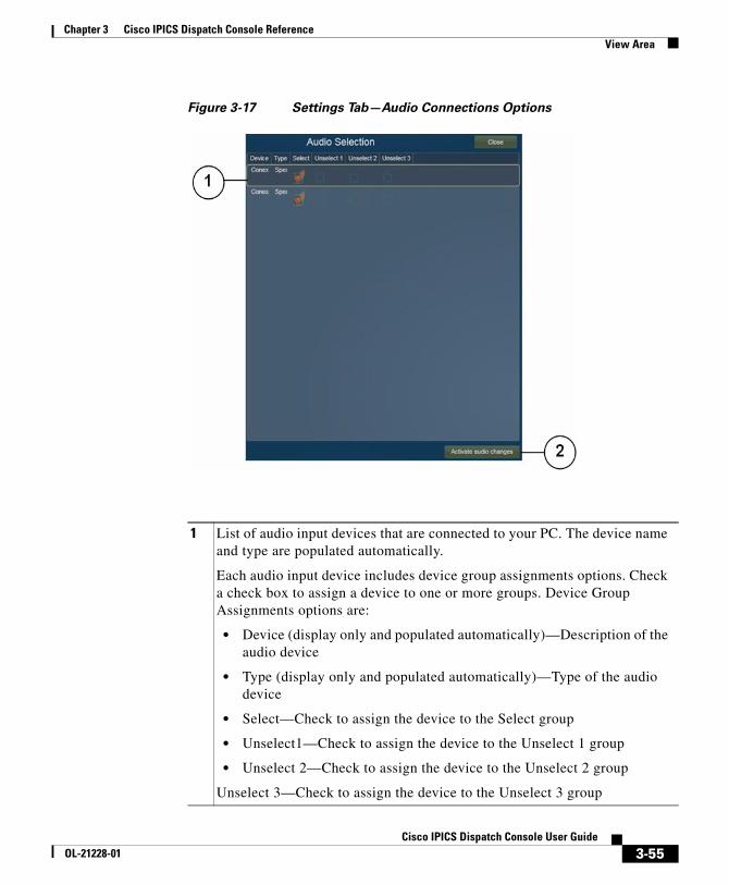
Chapter 3 Cisco IPICS Dispatch Console ReferenceView Area
Figure 3-17 Settings Tab—Audio Connections Options
1 List of audio input devices that are connected to your PC. The device name and type are populated automatically.
Each audio input device includes device group assignments options. Check a check box to assign a device to one or more groups. Device Group Assignments options are:
• Device (display only and populated automatically)—Description of the audio device
• Type (display only and populated automatically)—Type of the audio device
• Select—Check to assign the device to the Select group
• Unselect1—Check to assign the device to the Unselect 1 group
• Unselect 2—Check to assign the device to the Unselect 2 group
Unselect 3—Check to assign the device to the Unselect 3 group
3-55Cisco IPICS Dispatch Console User Guide
OL-21228-01
Chapter 3 Cisco IPICS Dispatch Console ReferenceView Area
Example
Consider a Cisco IPICS Dispatch Console system that is set up as follows:
• These audio output devices are configured on the client PC:
– Headset
– Headset left speaker
– Overhead speaker
• The Cisco IPICS Dispatch Console has three channels, called Channel 1, Channel 2, and Channel 3, and you want audio that these channels receive to play as follows:
– Channel 1—Headset
– Channel 2—Headset left speaker
– Channel 3—Headset left speaker and overhead speaker
To enable audio to play in this way, you could make the following configurations in the Cisco IPICS Dispatch Console:
• Audio connections configurations—In the Audio Connections area makes these assignments:
– Headset—Assigned to the Select group
– Headset left speaker—Assigned to the Unselect1 group and the Unselect2 group
– Overhead speaker—Assigned to the Unselect2 group
• Channel 1 configuration—Use the Audio Selection button to choose the Sel group. This setting sends audio from Channel 1 to the Select group, which causes that audio to play on the headset.
• Channel 2 configuration—Use the Audio Selection button to choose the U1 group. This setting sends audio from Channel 2 to the Unselect 1 group, which causes that audio to play on the headset left speaker.
2 Activate audio changes button—Click to update the Cisco IPICS Dispatch Console with any changes that you make in the Audio Connections area. These changes remain in effect when you exit the Cisco IPICS Dispatch Console.
3-56Cisco IPICS Dispatch Console User Guide
OL-21228-01
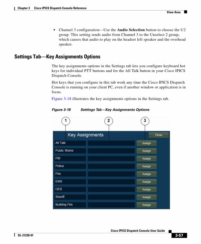
Chapter 3 Cisco IPICS Dispatch Console ReferenceView Area
• Channel 3 configuration—Use the Audio Selection button to choose the U2 group. This setting sends audio from Channel 3 to the Unselect 2 group, which causes that audio to play on the headset left speaker and the overhead speaker.
Settings Tab—Key Assignments Options
The key assignments options in the Settings tab lets you configure keyboard hot keys for individual PTT buttons and for the All Talk button in your Cisco IPICS Dispatch Console.
Hot keys that you configure in this tab work any time the Cisco IPICS Dispatch Console is running on your client PC, even if another window or application is in focus.
Figure 3-18 illustrates the key assignments options in the Settings tab.
Figure 3-18 Settings Tab—Key Assignments Options
3-57Cisco IPICS Dispatch Console User Guide
OL-21228-01
Chapter 3 Cisco IPICS Dispatch Console ReferenceView Area
Example
Assume that you want to configure your Cisco IPICS Dispatch Console so that pressing Left Shift + A operates the All Talk button, and L operates the PTT button for a channel called Police. To do so, on the Key Assignments tab, take these actions:
• Click the Key field to the right of the All Talk item, press Left Shift + A, then click the Assign button to the right of this Key field.
• Locate the Police item in the Resource list, click the Key field to the right of the Police item, press L, then click the Assign button to the right of this Key field.
Now, pressing Left Shift + A is equivalent to clicking the All Talk button, and pressing L is equivalent to clicking the PTT button for the Police channel.
1 Resource list—List each resource for which you can create a PTT hotkey.
The All Talk item indicates the IDC All Talk button. Other items are resources in your IDC.
2 Key fields—Enter the hotkey to be used to engage PTT for the corresponding resource. Valid hotkeys are:
• Letters E through Z
• Left Shift + any character
• Right Shift + any character
• Left Ctrl + any character
• Right Ctrl + any character
• Left Alt + any character
• Right Alt + any character
• Any combination of right and left Shift, Ctrl, Alt + any character
3 Assign buttons—Click to configure the key or key combination that you enter in the Key field as the hot key for the corresponding resource.
After you click an Assign button, it changes to Unassign. Click an Unassign button to remove the corresponding hot key assignment and clear the corresponding Key field.
3-58Cisco IPICS Dispatch Console User Guide
OL-21228-01
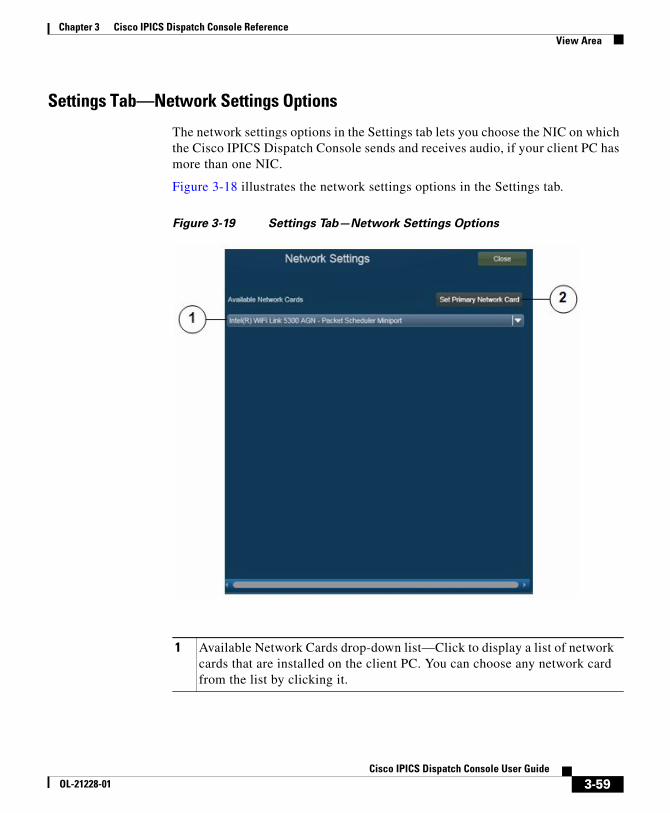
Chapter 3 Cisco IPICS Dispatch Console ReferenceView Area
Settings Tab—Network Settings Options
The network settings options in the Settings tab lets you choose the NIC on which the Cisco IPICS Dispatch Console sends and receives audio, if your client PC has more than one NIC.
Figure 3-18 illustrates the network settings options in the Settings tab.
Figure 3-19 Settings Tab—Network Settings Options
1 Available Network Cards drop-down list—Click to display a list of network cards that are installed on the client PC. You can choose any network card from the list by clicking it.
3-59Cisco IPICS Dispatch Console User Guide
OL-21228-01
Chapter 3 Cisco IPICS Dispatch Console ReferenceView Area
Adding a Resource to an Incident or VTG When you click the Add button after filtering incident resources in the Incident Details tab or VTG Details tab, a pop-up window appears. Use these pop-up windows to add resources to an incident or VTG.
The following section describe how to add resources to an incident or VTG:
• Adding a Channel, page 3-60
• Adding a User, page 3-62
• Adding a VTG, page 3-65
• Adding a Radio, page 3-66
• Adding an Image, page 3-68
• Adding Video, page 3-70
• Uploading Images, page 3-72
• Uploading Video, page 3-74
Adding a Channel
Figure 3-20 illustrates the Add a Channel pop-up window, which appears when you choose to add a channel to an incident or a VTG.
2 Set Primary Network Card button—Click to set the network card that you choose from the Available Network Cards drop-down list as the network card on which the Cisco IPICS Dispatch Console sends and receives audio.
3-60Cisco IPICS Dispatch Console User Guide
OL-21228-01
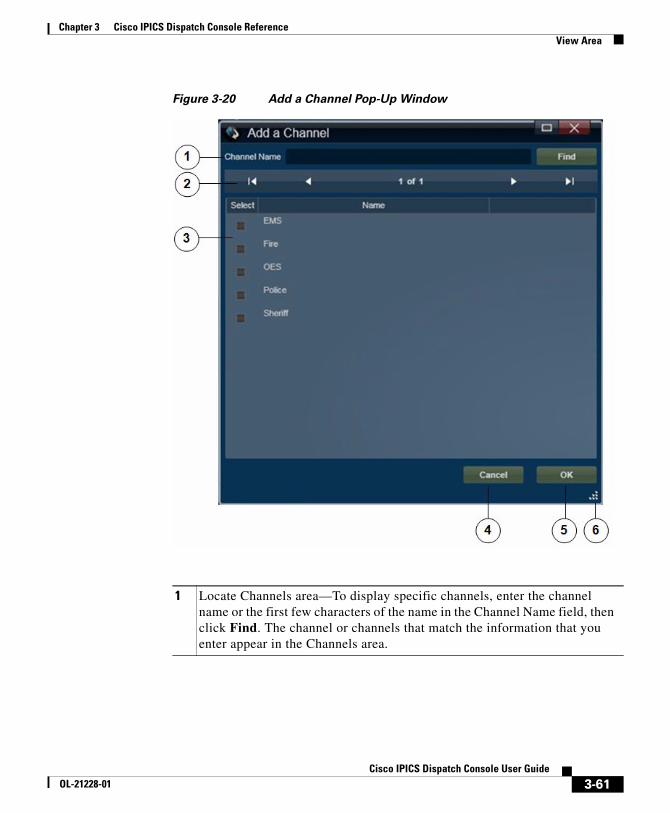
Chapter 3 Cisco IPICS Dispatch Console ReferenceView Area
Figure 3-20 Add a Channel Pop-Up Window
1 Locate Channels area—To display specific channels, enter the channel name or the first few characters of the name in the Channel Name field, then click Find. The channel or channels that match the information that you enter appear in the Channels area.
3-61Cisco IPICS Dispatch Console User Guide
OL-21228-01
Chapter 3 Cisco IPICS Dispatch Console ReferenceView Area
Adding a User
Figure 3-21 illustrates the Add a User pop-up window, which appears when you choose to add a user to an incident or a VTG.
2 Display control buttons—If the Channels area does not have enough room to display all available channels, use the following buttons to navigate through the channel display pages:
• —Click to display the first page of channels
• —Click to display the previous page of channels
• —Click to display the next page of channels
• —Click to display the last page of channels
3 Channels area—By default, displays all channels that are configured in the Cisco IPICS Administration Console. If you specify information and click the Find button in the Locate Channels area, this list displays only channels that match the find criteria. A marked check box appears next to a channel that is already added to the incident or VTG.
You can resize any column by dragging a border next to its name
To add one or more channels to an incident or VTG, check the check box next to each channel, then click OK.
4 Cancel button—Click to exit the Add a Channel pop-up window without adding a channel to the incident or VTG.
5 OK button—Click to add the selected channels to the incident or VTG.
6 Resize handle—Click and drag to resize the Add a Channel pop-up window.
3-62Cisco IPICS Dispatch Console User Guide
OL-21228-01
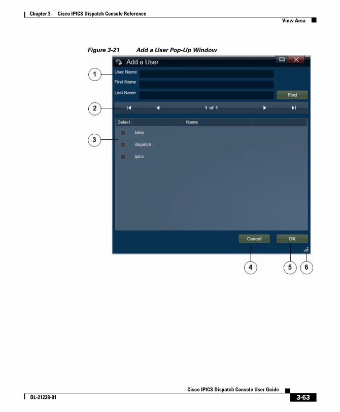
Chapter 3 Cisco IPICS Dispatch Console ReferenceView Area
Figure 3-21 Add a User Pop-Up Window
3-63Cisco IPICS Dispatch Console User Guide
OL-21228-01
Chapter 3 Cisco IPICS Dispatch Console ReferenceView Area
1 Locate User area—To display specific users, enter the name or the first few characters of the name in any or all of following fields, then click Find:
• User Name—Cisco IPICS user name of the user
• First Name—First name of the user as configured in the Cisco IPICS Administration Console
• Last Name—Last name of the user as configured in the Cisco IPICS Administration Console
The user or users that match the information that you enter appear in the Users area.
2 Display control buttons—If the Users area does not have enough room to display all available users, use the following buttons to navigate through the user display pages:
• —Click to display the first page of users
• —Click to display the previous page of users
• —Click to display the next page of users
• —Click to display the last page of users
3 Users area—By default, displays all users that are configured in the Cisco IPICS Administration Console. If you specify information and click the Find button in the Locate Users area, this list displays only users that match the find criteria. A marked check box appears next to a user that is already added to the incident or VTG.
You can resize any column by dragging a border next to its name
To add one or more users to an incident or VTG, check the check box next to each user, then click OK.
4 Cancel button—Click to exit the Add a User pop-up window without adding a user to the incident or VTG.
5 OK button—Click to add the selected users to the incident or VTG.
6 Resize handle—Click and drag to resize the Add a User pop-up window.
3-64Cisco IPICS Dispatch Console User Guide
OL-21228-01
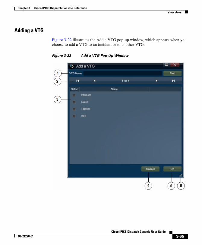
Chapter 3 Cisco IPICS Dispatch Console ReferenceView Area
Adding a VTG
Figure 3-22 illustrates the Add a VTG pop-up window, which appears when you choose to add a VTG to an incident or to another VTG.
Figure 3-22 Add a VTG Pop-Up Window
3-65Cisco IPICS Dispatch Console User Guide
OL-21228-01
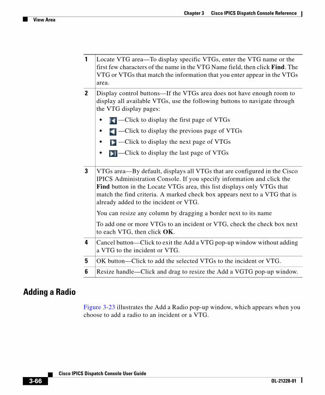
Chapter 3 Cisco IPICS Dispatch Console ReferenceView Area
Adding a Radio
Figure 3-23 illustrates the Add a Radio pop-up window, which appears when you choose to add a radio to an incident or a VTG.
1 Locate VTG area—To display specific VTGs, enter the VTG name or the first few characters of the name in the VTG Name field, then click Find. The VTG or VTGs that match the information that you enter appear in the VTGs area.
2 Display control buttons—If the VTGs area does not have enough room to display all available VTGs, use the following buttons to navigate through the VTG display pages:
• —Click to display the first page of VTGs
• —Click to display the previous page of VTGs
• —Click to display the next page of VTGs
• —Click to display the last page of VTGs
3 VTGs area—By default, displays all VTGs that are configured in the Cisco IPICS Administration Console. If you specify information and click the Find button in the Locate VTGs area, this list displays only VTGs that match the find criteria. A marked check box appears next to a VTG that is already added to the incident or VTG.
You can resize any column by dragging a border next to its name
To add one or more VTGs to an incident or VTG, check the check box next to each VTG, then click OK.
4 Cancel button—Click to exit the Add a VTG pop-up window without adding a VTG to the incident or VTG.
5 OK button—Click to add the selected VTGs to the incident or VTG.
6 Resize handle—Click and drag to resize the Add a VGTG pop-up window.
3-66Cisco IPICS Dispatch Console User Guide
OL-21228-01
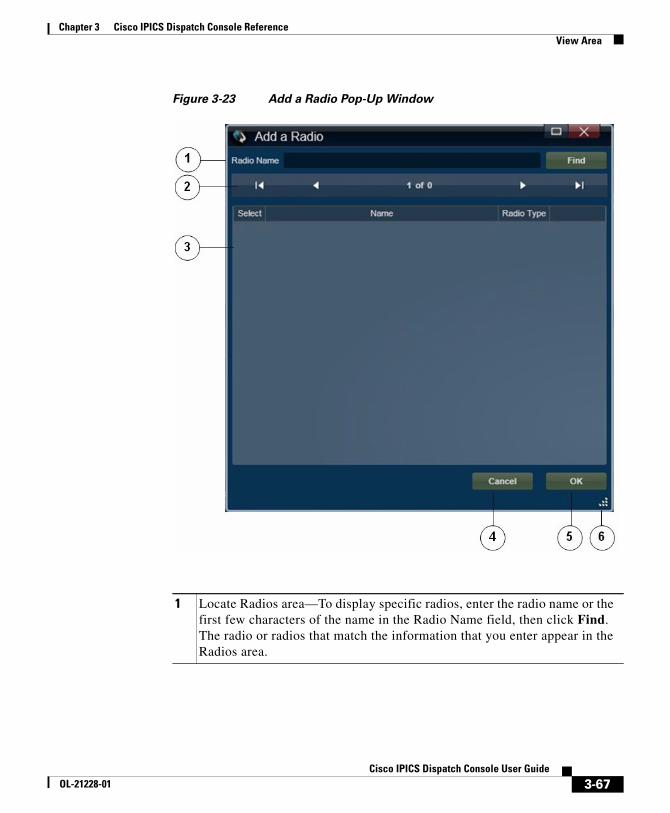
Chapter 3 Cisco IPICS Dispatch Console ReferenceView Area
Figure 3-23 Add a Radio Pop-Up Window
1 Locate Radios area—To display specific radios, enter the radio name or the first few characters of the name in the Radio Name field, then click Find. The radio or radios that match the information that you enter appear in the Radios area.
3-67Cisco IPICS Dispatch Console User Guide
OL-21228-01
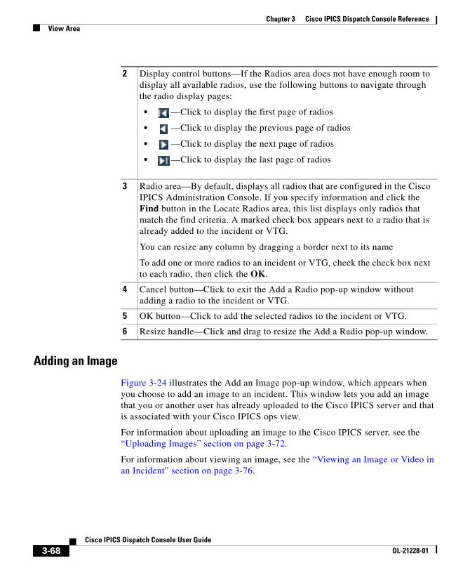
Chapter 3 Cisco IPICS Dispatch Console ReferenceView Area
Adding an Image
Figure 3-24 illustrates the Add an Image pop-up window, which appears when you choose to add an image to an incident. This window lets you add an image that you or another user has already uploaded to the Cisco IPICS server and that is associated with your Cisco IPICS ops view.
For information about uploading an image to the Cisco IPICS server, see the “Uploading Images” section on page 3-72.
For information about viewing an image, see the “Viewing an Image or Video in an Incident” section on page 3-76.
2 Display control buttons—If the Radios area does not have enough room to display all available radios, use the following buttons to navigate through the radio display pages:
• —Click to display the first page of radios
• —Click to display the previous page of radios
• —Click to display the next page of radios
• —Click to display the last page of radios
3 Radio area—By default, displays all radios that are configured in the Cisco IPICS Administration Console. If you specify information and click the Find button in the Locate Radios area, this list displays only radios that match the find criteria. A marked check box appears next to a radio that is already added to the incident or VTG.
You can resize any column by dragging a border next to its name
To add one or more radios to an incident or VTG, check the check box next to each radio, then click the OK.
4 Cancel button—Click to exit the Add a Radio pop-up window without adding a radio to the incident or VTG.
5 OK button—Click to add the selected radios to the incident or VTG.
6 Resize handle—Click and drag to resize the Add a Radio pop-up window.
3-68Cisco IPICS Dispatch Console User Guide
OL-21228-01
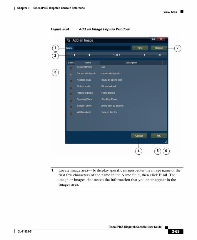
Chapter 3 Cisco IPICS Dispatch Console ReferenceView Area
Figure 3-24 Add an Image Pop-up Window
1 Locate Image area—To display specific images, enter the image name or the first few characters of the name in the Name field, then click Find. The image or images that match the information that you enter appear in the Images area.
3-69Cisco IPICS Dispatch Console User Guide
OL-21228-01
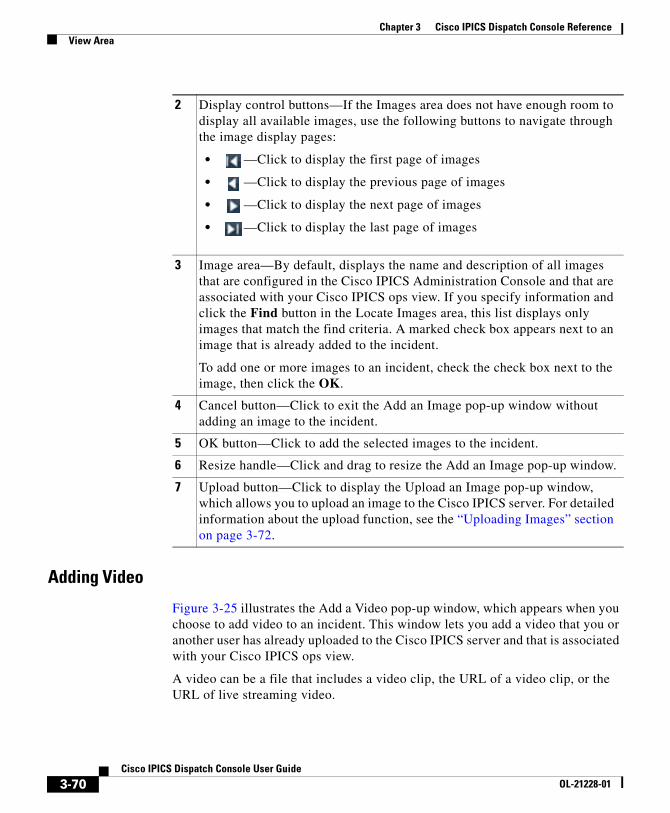
Chapter 3 Cisco IPICS Dispatch Console ReferenceView Area
Adding Video
Figure 3-25 illustrates the Add a Video pop-up window, which appears when you choose to add video to an incident. This window lets you add a video that you or another user has already uploaded to the Cisco IPICS server and that is associated with your Cisco IPICS ops view.
A video can be a file that includes a video clip, the URL of a video clip, or the URL of live streaming video.
2 Display control buttons—If the Images area does not have enough room to display all available images, use the following buttons to navigate through the image display pages:
• —Click to display the first page of images
• —Click to display the previous page of images
• —Click to display the next page of images
• —Click to display the last page of images
3 Image area—By default, displays the name and description of all images that are configured in the Cisco IPICS Administration Console and that are associated with your Cisco IPICS ops view. If you specify information and click the Find button in the Locate Images area, this list displays only images that match the find criteria. A marked check box appears next to an image that is already added to the incident.
To add one or more images to an incident, check the check box next to the image, then click the OK.
4 Cancel button—Click to exit the Add an Image pop-up window without adding an image to the incident.
5 OK button—Click to add the selected images to the incident.
6 Resize handle—Click and drag to resize the Add an Image pop-up window.
7 Upload button—Click to display the Upload an Image pop-up window, which allows you to upload an image to the Cisco IPICS server. For detailed information about the upload function, see the “Uploading Images” section on page 3-72.
3-70Cisco IPICS Dispatch Console User Guide
OL-21228-01
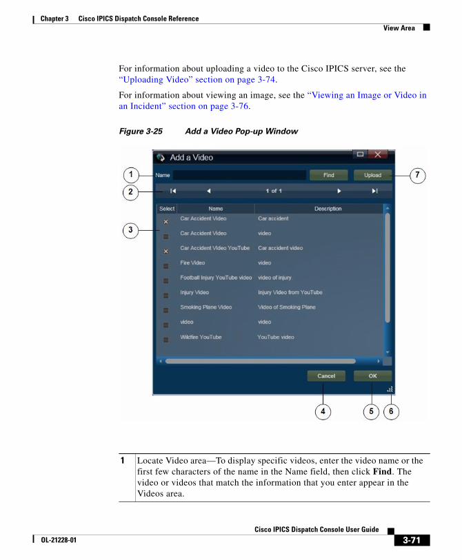
Chapter 3 Cisco IPICS Dispatch Console ReferenceView Area
For information about uploading a video to the Cisco IPICS server, see the “Uploading Video” section on page 3-74.
For information about viewing an image, see the “Viewing an Image or Video in an Incident” section on page 3-76.
Figure 3-25 Add a Video Pop-up Window
1 Locate Video area—To display specific videos, enter the video name or the first few characters of the name in the Name field, then click Find. The video or videos that match the information that you enter appear in the Videos area.
3-71Cisco IPICS Dispatch Console User Guide
OL-21228-01
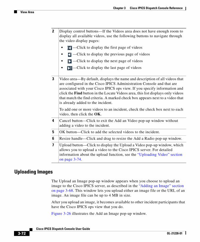
Chapter 3 Cisco IPICS Dispatch Console ReferenceView Area
Uploading Images
The Upload an Image pop-up window appears when you choose to upload an image to the Cisco IPICS server, as described in the “Adding an Image” section on page 3-68. This window lets you upload either an image file or the URL of an image. An image file can be up to 4 MB in size.
After you upload an image, it becomes available to other incident participants that have the Cisco IPICS ops view that you do.
Figure 3-26 illustrates the Add an Image pop-up window.
2 Display control buttons—If the Videos area does not have enough room to display all available videos, use the following buttons to navigate through the video display pages:
• —Click to display the first page of videos
• —Click to display the previous page of videos
• —Click to display the next page of videos
• —Click to display the last page of videos
3 Video area—By default, displays the name and description of all videos that are configured in the Cisco IPICS Administration Console and that are associated with your Cisco IPICS ops view. If you specify information and click the Find button in the Locate Videos area, this list displays only videos that match the find criteria. A marked check box appears next to a video that is already added to the incident.
To add one or more videos to an incident, check the check box next to each video, then click the OK.
4 Cancel button—Click to exit the Add an Video pop-up window without adding a video to the incident.
5 OK button—Click to add the selected videos to the incident.
6 Resize handle—Click and drag to resize the Add a Radio pop-up window.
7 Upload button—Click to display the Upload a Video pop-up window, which allows you to upload a video to the Cisco IPICS server. For detailed information about the upload function, see the “Uploading Video” section on page 3-74.
3-72Cisco IPICS Dispatch Console User Guide
OL-21228-01
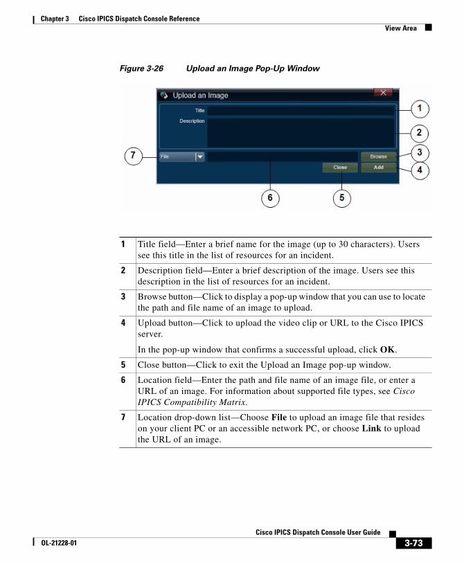
Chapter 3 Cisco IPICS Dispatch Console ReferenceView Area
Figure 3-26 Upload an Image Pop-Up Window
1 Title field—Enter a brief name for the image (up to 30 characters). Users see this title in the list of resources for an incident.
2 Description field—Enter a brief description of the image. Users see this description in the list of resources for an incident.
3 Browse button—Click to display a pop-up window that you can use to locate the path and file name of an image to upload.
4 Upload button—Click to upload the video clip or URL to the Cisco IPICS server.
In the pop-up window that confirms a successful upload, click OK.
5 Close button—Click to exit the Upload an Image pop-up window.
6 Location field—Enter the path and file name of an image file, or enter a URL of an image. For information about supported file types, see Cisco IPICS Compatibility Matrix.
7 Location drop-down list—Choose File to upload an image file that resides on your client PC or an accessible network PC, or choose Link to upload the URL of an image.
3-73Cisco IPICS Dispatch Console User Guide
OL-21228-01
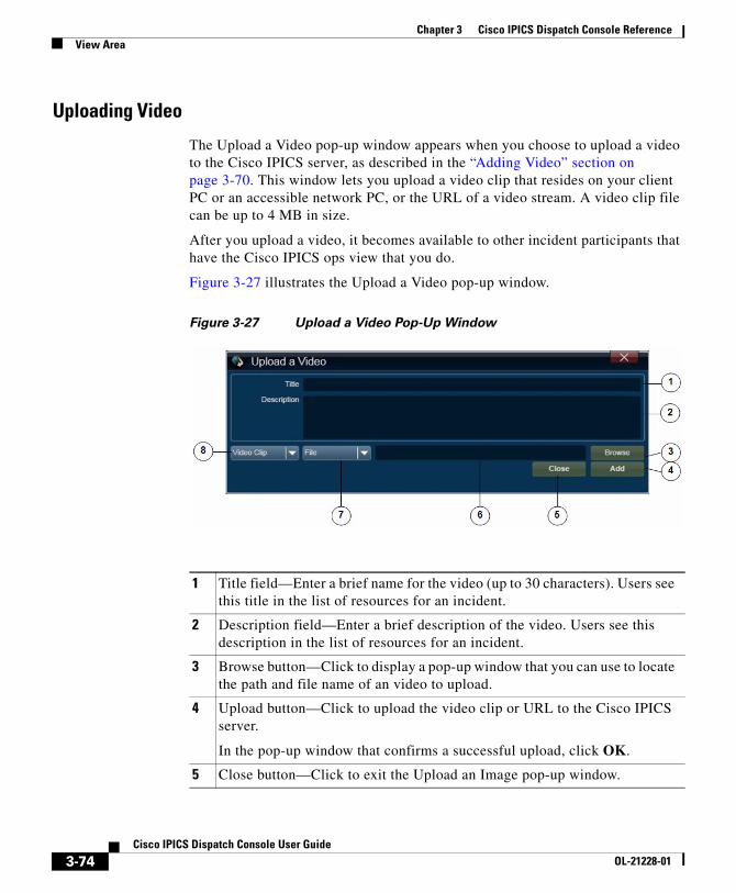
Chapter 3 Cisco IPICS Dispatch Console ReferenceView Area
Uploading Video
The Upload a Video pop-up window appears when you choose to upload a video to the Cisco IPICS server, as described in the “Adding Video” section on page 3-70. This window lets you upload a video clip that resides on your client PC or an accessible network PC, or the URL of a video stream. A video clip file can be up to 4 MB in size.
After you upload a video, it becomes available to other incident participants that have the Cisco IPICS ops view that you do.
Figure 3-27 illustrates the Upload a Video pop-up window.
Figure 3-27 Upload a Video Pop-Up Window
1 Title field—Enter a brief name for the video (up to 30 characters). Users see this title in the list of resources for an incident.
2 Description field—Enter a brief description of the video. Users see this description in the list of resources for an incident.
3 Browse button—Click to display a pop-up window that you can use to locate the path and file name of an video to upload.
4 Upload button—Click to upload the video clip or URL to the Cisco IPICS server.
In the pop-up window that confirms a successful upload, click OK.
5 Close button—Click to exit the Upload an Image pop-up window.
3-74Cisco IPICS Dispatch Console User Guide
OL-21228-01
Chapter 3 Cisco IPICS Dispatch Console ReferenceView Area
Obtaining a Source URL for a YouTube Video
To upload a YouTube video to the Cisco IPICS server, you must enter the source URL for the video, which is the actual path to the video. The source URL is different than the URL that appears in the Address field of your browser when you view the video from the YouTube web page.
6 Location field—Enter the location of the video. Use one of the following formats, based on the option that you choose from the Type drop-down list (see row 8 in this table):
• VSM—Enter a URL in bwims format (bwims://<server>/<proxy_name>).
• YouTube—Enter the source URL for the YouTube video. For more information, see the “Obtaining a Source URL for a YouTube Video” section on page 3-75.
• Live Video—Enter the URL of the video stream. To designate live video from a VSM source, use the format http://<server>/video.jpg?source=<proxy name>.
• Video Clip—Enter the path and file name of the video clip, or the URL of the clip.
For information about supported video types, see Cisco IPICS Compatibility Matrix. For detailed information about URLs for VSM video, see your VSM documentation.
7 Location drop-down list—This list is available only if you choose Video Clip from Type drop-down list. Choose File to upload a video file that resides on your client PC or an accessible network PC, or choose Link to upload the URL of a video file.
8 Type drop-down list—Choose the type of video that you are downloading
• VSM—Video proxy from Cisco Video Surveillance Manager (VSM)
• YouTube—YouTube video
• Live Video—Streaming live video, typically from a video camera
• Video Clip—File that contains a video clip
3-75Cisco IPICS Dispatch Console User Guide
OL-21228-01
Chapter 3 Cisco IPICS Dispatch Console ReferenceView Area
To obtain the source URL for a YouTube video, follow these steps:
Procedure
Step 1 Go to the YouTube website and navigate to the video that you want to upload.
Step 2 On the YouTube website, copy the data that appear in the Embed field, which is near the top right of the page.
Step 3 Open a text editor and paste the data that you copied.
Step 4 Look for the URL that appears in the src tag.
For example, in the following data that was copied from the Embed field for a YouTube video, the src tag is highlighted in bold type:
<object width="480" height="385"><param name="movie" value="http://www.youtube.com/v/a_movie"></param><param name="allowFullScreen" value="true"></param><param name="allowscriptaccess" value="always"></param><embed src="http://www.youtube.com/v/a_movie" type="application/x-shockwave-flash" allowscriptaccess="always" allowfullscreen="true" width="480" height="385"></embed></object>
The source URL appears within quotes in the source tag. In this example, the source URL that should be used in Location field in the Upload a Video pop-up window is:
http://www.youtube.com/v/a_movie
Viewing an Image or Video in an IncidentTo view an image or video, double-click its name or icon in the Incident Details tab. The View an Image or Video pop-up window appears. Figure 3-26 illustrates this window.
3-76Cisco IPICS Dispatch Console User Guide
OL-21228-01
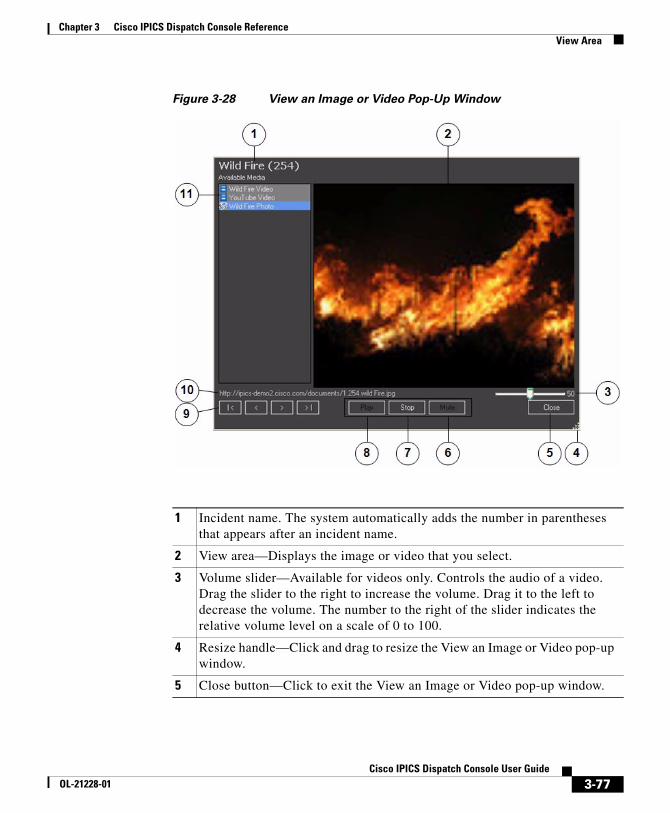
Chapter 3 Cisco IPICS Dispatch Console ReferenceView Area
Figure 3-28 View an Image or Video Pop-Up Window
1 Incident name. The system automatically adds the number in parentheses that appears after an incident name.
2 View area—Displays the image or video that you select.
3 Volume slider—Available for videos only. Controls the audio of a video. Drag the slider to the right to increase the volume. Drag it to the left to decrease the volume. The number to the right of the slider indicates the relative volume level on a scale of 0 to 100.
4 Resize handle—Click and drag to resize the View an Image or Video pop-up window.
5 Close button—Click to exit the View an Image or Video pop-up window.
3-77Cisco IPICS Dispatch Console User Guide
OL-21228-01
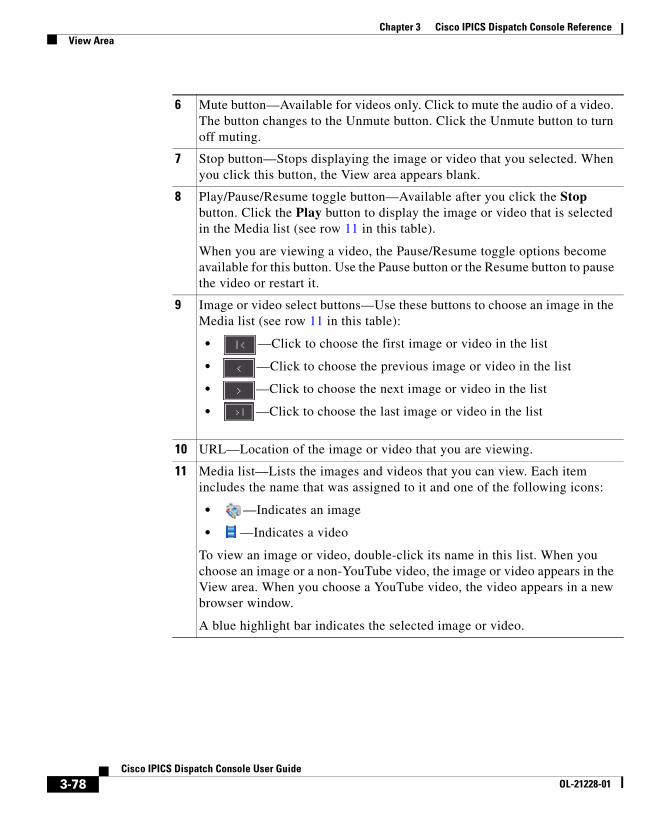
Chapter 3 Cisco IPICS Dispatch Console ReferenceView Area
6 Mute button—Available for videos only. Click to mute the audio of a video. The button changes to the Unmute button. Click the Unmute button to turn off muting.
7 Stop button—Stops displaying the image or video that you selected. When you click this button, the View area appears blank.
8 Play/Pause/Resume toggle button—Available after you click the Stop button. Click the Play button to display the image or video that is selected in the Media list (see row 11 in this table).
When you are viewing a video, the Pause/Resume toggle options become available for this button. Use the Pause button or the Resume button to pause the video or restart it.
9 Image or video select buttons—Use these buttons to choose an image in the Media list (see row 11 in this table):
• —Click to choose the first image or video in the list
• —Click to choose the previous image or video in the list
• —Click to choose the next image or video in the list
• —Click to choose the last image or video in the list
10 URL—Location of the image or video that you are viewing.
11 Media list—Lists the images and videos that you can view. Each item includes the name that was assigned to it and one of the following icons:
• —Indicates an image
• —Indicates a video
To view an image or video, double-click its name in this list. When you choose an image or a non-YouTube video, the image or video appears in the View area. When you choose a YouTube video, the video appears in a new browser window.
A blue highlight bar indicates the selected image or video.
3-78Cisco IPICS Dispatch Console User Guide
OL-21228-01
Chapter 3 Cisco IPICS Dispatch Console ReferenceItems Tabs Area
Items Tabs AreaThe Items Tabs area appears at the top right of the Cisco IPICS Dispatch Console Main Window (see Figure 3-1 on page 3-2). It provides tabs that list VTGs, incidents, and policies, and that provide quick access to detailed information about any of these items. It also provides options for creating VTGs and incidents, and for activating policies.
The tabs and information that you can access in the Items Tabs area depend on your Cisco IPICS role:
• Only users with the Dispatcher role or All role and a Platinum User license can access the VTGs tab.
• Only users with the Dispatcher role or All role and a Platinum User license can access the Incidents tab.
• Users with the Dispatcher role or All role see all policies that are configured in the Cisco IPICS Administration Console. Other users see only policies with which they are associated.
The Items Tabs area appears by default when you start the Cisco IPICS Dispatch Console, but you can hide it by clicking the Hide button , which appears to the right of the Items Tabs area. The button changes to the Show button . Click the Show button to display the Items Tabs area when it is hidden. (These buttons also affect the Dial Pad and Channel Patch area, if it is displayed.)
The following sections describe the tabs that are in the Items Tabs area:
• VTGs Tab, page 3-79
• Incidents Tab, page 3-81
• Policies Tab, page 3-85
VTGs TabThe VTGs tab lists the VTGs that are configured in the Cisco IPICS Administration Console. It also lets you create a VTG. Figure 3-29 illustrates the VTGs tab.
3-79Cisco IPICS Dispatch Console User Guide
OL-21228-01
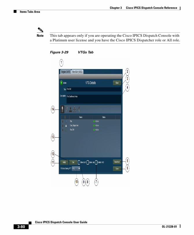
Chapter 3 Cisco IPICS Dispatch Console ReferenceItems Tabs Area
Note This tab appears only if you are operating the Cisco IPICS Dispatch Console with a Platinum user license and you have the Cisco IPICS Dispatcher role or All role.
Figure 3-29 VTGs Tab
3-80Cisco IPICS Dispatch Console User Guide
OL-21228-01
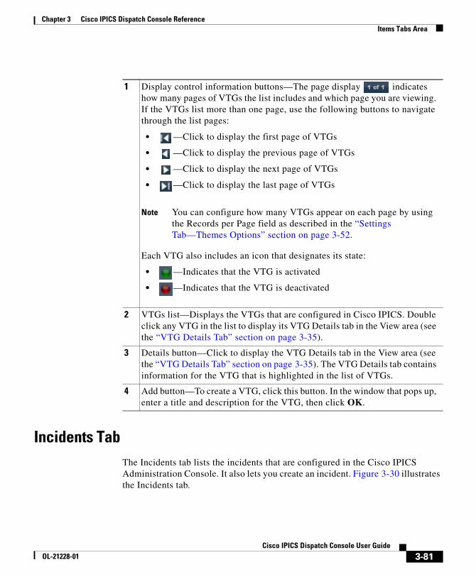
Chapter 3 Cisco IPICS Dispatch Console ReferenceItems Tabs Area
Incidents TabThe Incidents tab lists the incidents that are configured in the Cisco IPICS Administration Console. It also lets you create an incident. Figure 3-30 illustrates the Incidents tab.
1 Display control information buttons—The page display indicates how many pages of VTGs the list includes and which page you are viewing. If the VTGs list more than one page, use the following buttons to navigate through the list pages:
• —Click to display the first page of VTGs
• —Click to display the previous page of VTGs
• —Click to display the next page of VTGs
• —Click to display the last page of VTGs
Note You can configure how many VTGs appear on each page by using the Records per Page field as described in the “Settings Tab—Themes Options” section on page 3-52.
Each VTG also includes an icon that designates its state:
• —Indicates that the VTG is activated
• —Indicates that the VTG is deactivated
2 VTGs list—Displays the VTGs that are configured in Cisco IPICS. Double click any VTG in the list to display its VTG Details tab in the View area (see the “VTG Details Tab” section on page 3-35).
3 Details button—Click to display the VTG Details tab in the View area (see the “VTG Details Tab” section on page 3-35). The VTG Details tab contains information for the VTG that is highlighted in the list of VTGs.
4 Add button—To create a VTG, click this button. In the window that pops up, enter a title and description for the VTG, then click OK.
3-81Cisco IPICS Dispatch Console User Guide
OL-21228-01
Chapter 3 Cisco IPICS Dispatch Console ReferenceItems Tabs Area
If an incident has been deactivated in the Cisco IPICS Administration console, a pop-up window with the following message appears when you access the Incidents tab for that incident:
“Warning: Incident has been deactivated and functionalities are disabled.”
In this case, you can view information about the incident, but you cannot make changes to it (add or remove resources), and you cannot activate its incident VTG.
Note This tab appears only if you are operating the Cisco IPICS Dispatch Console with a Platinum user license and you have the Cisco IPICS Dispatcher role or All role.
3-82Cisco IPICS Dispatch Console User Guide
OL-21228-01
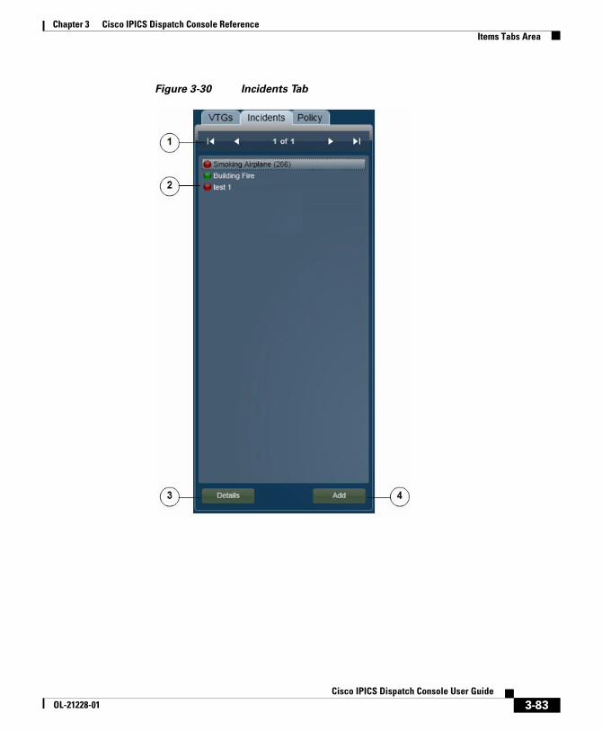
Chapter 3 Cisco IPICS Dispatch Console ReferenceItems Tabs Area
Figure 3-30 Incidents Tab
3-83Cisco IPICS Dispatch Console User Guide
OL-21228-01

Chapter 3 Cisco IPICS Dispatch Console ReferenceItems Tabs Area
1 Display control information buttons—The page display indicates how many pages of incidents the list includes and which page you are viewing. If the incidents list includes more than one page, use the following buttons to navigate through the list pages:
• —Click to display the first page of incidents
• —Click to display the previous page of incidents
• —Click to display the next page of incidents
• —Click to display the last page of incidents
Note You can configure how many incidents appear on each page by using the Records per Page field as described in the “Settings Tab—Themes Options” section on page 3-52.
Each incident also includes an icon that designates the state of its incident VTG:
• —Indicates that the incident VTG is activated
• —Indicates that the incident is VTG deactivated
2 Incidents list—Displays the incidents that are active in the Cisco IPICS Administration Console. Double click any incident in the list to display its Incident Details tab in the View area (see the “Incident Details Tab” section on page 3-40).
The system automatically adds the number in parentheses that appears after an incident name, and increments it by one for each new VTG.
3 Details button—Click to display the Incident Details tab in the View area (see the “Incident Details Tab” section on page 3-40). The Incident Details tab contains information for the incident that is highlighted in the list of incidents.
4 Add button—To create an incident, click this button. In the window that pops up, enter a title and description for the incident, then click OK.
When you create an incident, it immediately becomes active in the Cisco Administration Console and you are added as a participant. Incident participants cannot communicate with each other until the incident VTG is activated for the incident.
3-84Cisco IPICS Dispatch Console User Guide
OL-21228-01
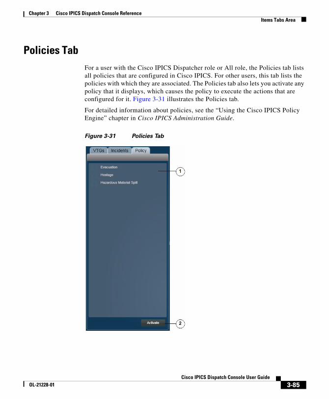
Chapter 3 Cisco IPICS Dispatch Console ReferenceItems Tabs Area
Policies TabFor a user with the Cisco IPICS Dispatcher role or All role, the Policies tab lists all policies that are configured in Cisco IPICS. For other users, this tab lists the policies with which they are associated. The Policies tab also lets you activate any policy that it displays, which causes the policy to execute the actions that are configured for it. Figure 3-31 illustrates the Policies tab.
For detailed information about policies, see the “Using the Cisco IPICS Policy Engine” chapter in Cisco IPICS Administration Guide.
Figure 3-31 Policies Tab
3-85Cisco IPICS Dispatch Console User Guide
OL-21228-01
Chapter 3 Cisco IPICS Dispatch Console ReferenceDial Pad and Channel Patch Area
Dial Pad and Channel Patch AreaThe Dial Pad and Channel Patch area provides access to the IDC dialer feature, which lets you place up to two telephone calls and optionally patch each call to a selected resource. Patching establishes audio communication between the end device on the call and the audio devices in the resource.
This area is hidden by default when you start the Cisco IPICS Dispatch Console. To display it, click the Show button next to Dial Pad & Channel Patch, which appears under the Items Tabs area.
Note • If you cannot see the Dial Pad and Channel Patch area or the Items Tabs area, the Items Tabs area is hidden. Click the Show button next to the right of the View area to see the Dial Pad and Channel Patch area and the Items Tabs area.
• The Dial Pad and Channel Patch area is available for users with the Cisco IPICS Dispatcher role or All role only.
The IDC dialer feature requires the following configuration in the Cisco IPICS Administration Console and that the Cisco IPICS Dispatch Console be registered with Cisco Unified Communications Manager or Cisco Unified Communications Manager Express:
• CUCM Settings for IDC Dialer options in the Administration > Options window
1 Policy list—For user with the Cisco IPICS Dispatcher role or All role, displays all policies. For other user types, displays the policies with which they are associated.
To activate a policy, check the check box next to the policy, then click the Activate button
Note To determine information about the execution of a policy, see the “Policy Execution Status Tab” section on page 3-48.
2 Activate button—Click to activate selected policies. When activated, a policy begins to execute the actions that are configured for it.
3-86Cisco IPICS Dispatch Console User Guide
OL-21228-01
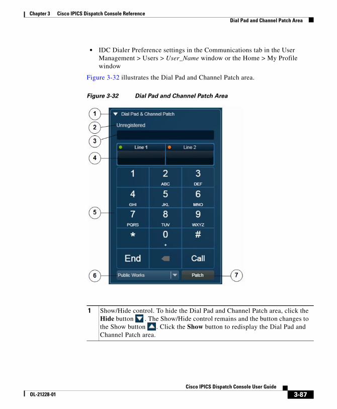
Chapter 3 Cisco IPICS Dispatch Console ReferenceDial Pad and Channel Patch Area
• IDC Dialer Preference settings in the Communications tab in the User Management > Users > User_Name window or the Home > My Profile window
Figure 3-32 illustrates the Dial Pad and Channel Patch area.
Figure 3-32 Dial Pad and Channel Patch Area
1 Show/Hide control. To hide the Dial Pad and Channel Patch area, click the Hide button . The Show/Hide control remains and the button changes to the Show button . Click the Show button to redisplay the Dial Pad and Channel Patch area.
3-87Cisco IPICS Dispatch Console User Guide
OL-21228-01
Chapter 3 Cisco IPICS Dispatch Console ReferenceDial Pad and Channel Patch Area
2 Status message—Provides information about configuration for the dial functionality. Messages include:
• Registered <phone_number>—The Cisco IPICS Dispatch Console is registered with Cisco Unified Communications Manager or Cisco Unified Communications Manager Express. <phone_number> is the number that the Cisco IPICS Dispatch Console uses to register with Cisco Unified Communications Manager or Cisco Unified Communications Manager Express.
• Unregistered—The Cisco IPICS Dispatch Console is not registered with Cisco Unified Communications Manager or Cisco Unified Communications Manager Express.
• Messages that the Cisco IPICS Dispatch Console receives from the client PC WAVE Engine service.
3 Displays the number that you are dialing. You can edit a number in this field by clicking it and using your PC keyboard or by using the dial pad (see row 5 in this table).
3-88Cisco IPICS Dispatch Console User Guide
OL-21228-01
Chapter 3 Cisco IPICS Dispatch Console ReferenceDial Pad and Channel Patch Area
4 Line Information area. Click this area to activate a line for dialing. A green icon in the upper left corner of this area indicates the line that call operations (including dial pad buttons) affect. An amber icon indicates an inactive line.
This area also displays status of a line. Status designations for each line include the following text and icons:
• Connecting—The system is dialing a telephone number
• On Call —A call is active
• On Hold —You placed a call on hold
• Held Remote —The device that the line is connected to placed the call on hold
• On Patch (<channel>) —The line is patched to the channel that is indicated
• Parked (<channel>) —The line that is patched to the indicated channel is on hold.
When you place two telephone calls, the Cisco IPICS Dispatch Console automatically puts the first call on hold when you click the other Line Information area to place the second call. After both calls are established, clicking one Line Information area releases the call on that line from hold area puts the call on the other line on hold.
5 Dial pad—Includes these buttons:
• Digits 0 through 9, star (*), pound (#)—To dial a call, click to enter the digit or symbol in the selected Line Information area. You can also use these buttons to send dual-tone multi-frequency (DTMF) tones on an active call.
• Backspace —Click to delete the character to the left of the cursor in the selected Line Information area.
• End—Click to terminate the call in the selected Line Information area.
• Call—Click to dial the number in the selected Line Information area.
• Hld/Res toggle—Replaces the Call button when a call is active. Click the Hld button to put the call in the selected Line Information area on hold. Click the Res button to take the call in the selected Line Information area off hold.
6 Resource list—Choose the resource to which to patch a call.
3-89Cisco IPICS Dispatch Console User Guide
OL-21228-01

Chapter 3 Cisco IPICS Dispatch Console ReferenceSystem Information Area
To use the Dial Pad and Channel Patch area to establish and optionally patch a call to a channel, follow these steps:
Procedure
Step 1 Click the Line 1 or Line 2 area to indicate the line on which you want to establish the call.
Step 2 Use the dial pad or your PC keyboard to enter the telephone number to call.
If you need to correct an entry, click the backspace button (<) on the Dial Pad or click the telephone number and use your PC keyboard keys.
Step 3 Click the Call button in the dial pad.
Step 4 (Optional) To patch a call to a resource, take these actions:
a. Click the line information for the active call that you want to patch.
b. Choose the channel from the Channel list.
c. Click the Patch button.
Step 5 To end the call, click the End button.
System Information AreaThe System Information area appears at the lower right of the Cisco IPICS Dispatch Console Main window. This area displays the system time, your Cisco IPICS user name, and the location to which the Cisco IPICS Dispatch Console is connected.
To hide the System Information area, the Master Audio Controls area, and the All Talk and Patch Controls area, click the Hide button at the bottom of the Cisco IPICS Dispatch Console Main window, directly under the Cisco logo. The button changes to the Show button . Click the Show button to redisplay these areas.
Figure 3-33 illustrates the System Information area.
7 Patch button—Click to patch the selected call to the resource that you choose from the Resource list.
3-90Cisco IPICS Dispatch Console User Guide
OL-21228-01
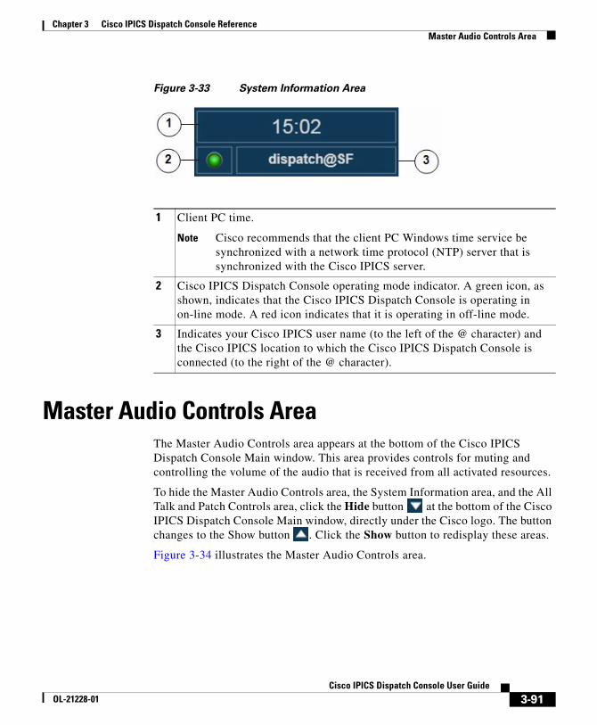
Chapter 3 Cisco IPICS Dispatch Console ReferenceMaster Audio Controls Area
Figure 3-33 System Information Area
Master Audio Controls AreaThe Master Audio Controls area appears at the bottom of the Cisco IPICS Dispatch Console Main window. This area provides controls for muting and controlling the volume of the audio that is received from all activated resources.
To hide the Master Audio Controls area, the System Information area, and the All Talk and Patch Controls area, click the Hide button at the bottom of the Cisco IPICS Dispatch Console Main window, directly under the Cisco logo. The button changes to the Show button . Click the Show button to redisplay these areas.
Figure 3-34 illustrates the Master Audio Controls area.
1 Client PC time.
Note Cisco recommends that the client PC Windows time service be synchronized with a network time protocol (NTP) server that is synchronized with the Cisco IPICS server.
2 Cisco IPICS Dispatch Console operating mode indicator. A green icon, as shown, indicates that the Cisco IPICS Dispatch Console is operating in on-line mode. A red icon indicates that it is operating in off-line mode.
3 Indicates your Cisco IPICS user name (to the left of the @ character) and the Cisco IPICS location to which the Cisco IPICS Dispatch Console is connected (to the right of the @ character).
3-91Cisco IPICS Dispatch Console User Guide
OL-21228-01
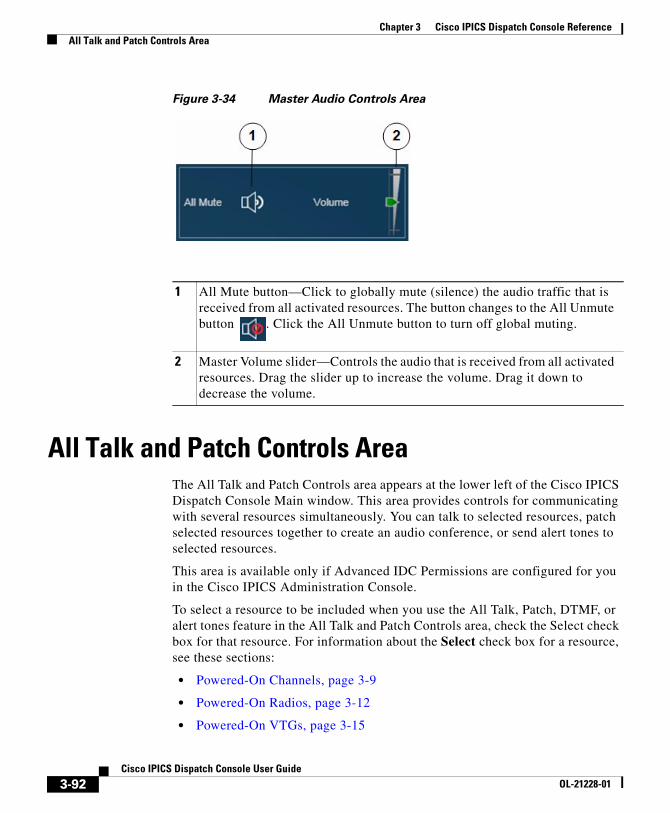
Chapter 3 Cisco IPICS Dispatch Console ReferenceAll Talk and Patch Controls Area
Figure 3-34 Master Audio Controls Area
All Talk and Patch Controls AreaThe All Talk and Patch Controls area appears at the lower left of the Cisco IPICS Dispatch Console Main window. This area provides controls for communicating with several resources simultaneously. You can talk to selected resources, patch selected resources together to create an audio conference, or send alert tones to selected resources.
This area is available only if Advanced IDC Permissions are configured for you in the Cisco IPICS Administration Console.
To select a resource to be included when you use the All Talk, Patch, DTMF, or alert tones feature in the All Talk and Patch Controls area, check the Select check box for that resource. For information about the Select check box for a resource, see these sections:
• Powered-On Channels, page 3-9
• Powered-On Radios, page 3-12
• Powered-On VTGs, page 3-15
1 All Mute button—Click to globally mute (silence) the audio traffic that is received from all activated resources. The button changes to the All Unmute button . Click the All Unmute button to turn off global muting.
2 Master Volume slider—Controls the audio that is received from all activated resources. Drag the slider up to increase the volume. Drag it down to decrease the volume.
3-92Cisco IPICS Dispatch Console User Guide
OL-21228-01
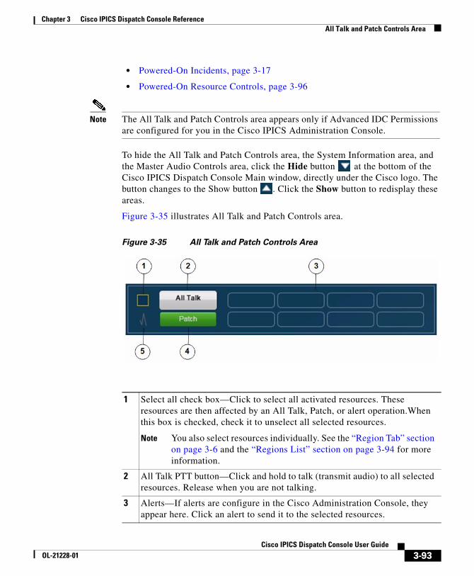
Chapter 3 Cisco IPICS Dispatch Console ReferenceAll Talk and Patch Controls Area
• Powered-On Incidents, page 3-17
• Powered-On Resource Controls, page 3-96
Note The All Talk and Patch Controls area appears only if Advanced IDC Permissions are configured for you in the Cisco IPICS Administration Console.
To hide the All Talk and Patch Controls area, the System Information area, and the Master Audio Controls area, click the Hide button at the bottom of the Cisco IPICS Dispatch Console Main window, directly under the Cisco logo. The button changes to the Show button . Click the Show button to redisplay these areas.
Figure 3-35 illustrates All Talk and Patch Controls area.
Figure 3-35 All Talk and Patch Controls Area
1 Select all check box—Click to select all activated resources. These resources are then affected by an All Talk, Patch, or alert operation.When this box is checked, check it to unselect all selected resources.
Note You also select resources individually. See the “Region Tab” section on page 3-6 and the “Regions List” section on page 3-94 for more information.
2 All Talk PTT button—Click and hold to talk (transmit audio) to all selected resources. Release when you are not talking.
3 Alerts—If alerts are configure in the Cisco Administration Console, they appear here. Click an alert to send it to the selected resources.
3-93Cisco IPICS Dispatch Console User Guide
OL-21228-01
Chapter 3 Cisco IPICS Dispatch Console ReferenceRegions List
Regions ListThe Regions list appears at the upper left of the Cisco IPICS Dispatch Console Main window. This list shows the regions that are configured in the Cisco IPICS Administration Console and provides controls for the resources in each region.
The Regions list appears by default when you start the Cisco IPICS Dispatch Console, but you can hide it by clicking the Hide button , which appears to the right of the Items Tabs area. The button changes to the Show button . Click the Show button to display the Regions list when it is hidden.
Figure 3-36 illustrates Regions list.
4 Patch button—Click to patch (connect) selected resources to each other. The button changes to Unpatch. Click the Unpatch button to remove the patch that is in effect between channels.
5 DTMF button—Click to enter dual-tone multi-frequency (DTMF) mode. The button turns green. Click it again to exit DTMF mode.
In DTMF mode, the Cisco IPICS Dispatch Console sends DTMF information to the selected tone control radio when you press a number 0 through 9 or a letter A through D on your client PC keyboard.
3-94Cisco IPICS Dispatch Console User Guide
OL-21228-01
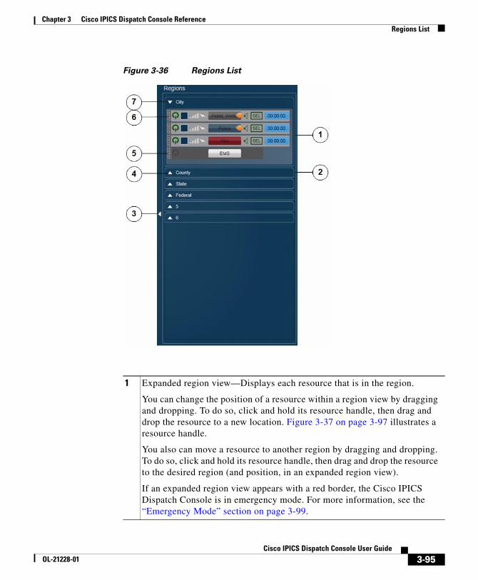
Chapter 3 Cisco IPICS Dispatch Console ReferenceRegions List
Figure 3-36 Regions List
1 Expanded region view—Displays each resource that is in the region.
You can change the position of a resource within a region view by dragging and dropping. To do so, click and hold its resource handle, then drag and drop the resource to a new location. Figure 3-37 on page 3-97 illustrates a resource handle.
You also can move a resource to another region by dragging and dropping. To do so, click and hold its resource handle, then drag and drop the resource to the desired region (and position, in an expanded region view).
If an expanded region view appears with a red border, the Cisco IPICS Dispatch Console is in emergency mode. For more information, see the “Emergency Mode” section on page 3-99.
3-95Cisco IPICS Dispatch Console User Guide
OL-21228-01
Chapter 3 Cisco IPICS Dispatch Console ReferenceRegions List
Powered-On Resource ControlsA powered-on resource appears in the Regions list as described in Figure 3-36. The Regions list provides controls and information for powered-on resources. Figure 3-37 describes these items.
Note Many of these items are duplicated for a resource in the Region tab. For more information, see the “Region Tab” section on page 3-6.
2 Collapsed region view.
If a collapsed region view flashes red, the Cisco IPICS Dispatch Console is in emergency mode. For more information, see the “Emergency Mode” section on page 3-99.
3 Hide Regions List button—Click to hide the Regions list. The button changes to the Show button . Click the Show button to display the Regions list when it is hidden.
4 Show Region View button—Click to expand a collapsed region view.
5 Powered off resource. To power on a resource that is powered off, click the Power button .
This button can appear in the following states:
• Gray—Indicates a powered-off resource.
• Green—Indicates a powered-on resource.
• Gold—Indicates a resource that is in the process of powering on. This button remains in this state if Cisco IPICS is unable to allocate system resources that are required to power on. In this case, try to power on the resource again.
Note You also can click a Power button in the Region tab to activate a resource.
6 Powered on resource. For detailed information about controls for a powered-on resource, see the “Powered-On Resource Controls” section on page 3-96.
7 Hide Region View button—Click to collapse an expanded region view.
3-96Cisco IPICS Dispatch Console User Guide
OL-21228-01
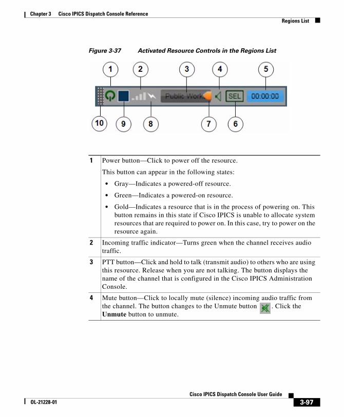
Chapter 3 Cisco IPICS Dispatch Console ReferenceRegions List
Figure 3-37 Activated Resource Controls in the Regions List
1 Power button—Click to power off the resource.
This button can appear in the following states:
• Gray—Indicates a powered-off resource.
• Green—Indicates a powered-on resource.
• Gold—Indicates a resource that is in the process of powering on. This button remains in this state if Cisco IPICS is unable to allocate system resources that are required to power on. In this case, try to power on the resource again.
2 Incoming traffic indicator—Turns green when the channel receives audio traffic.
3 PTT button—Click and hold to talk (transmit audio) to others who are using this resource. Release when you are not talking. The button displays the name of the channel that is configured in the Cisco IPICS Administration Console.
4 Mute button—Click to locally mute (silence) incoming audio traffic from the channel. The button changes to the Unmute button . Click the Unmute button to unmute.
3-97Cisco IPICS Dispatch Console User Guide
OL-21228-01
Chapter 3 Cisco IPICS Dispatch Console ReferenceRegions List
5 Audio Received time stamp—Displays the time that the resource last received an audio transmission. You can double-click this time stamp to display the expanded audio controls for the resource (see the “Audio Replay Controls for Resources” section on page 3-20.)
For last call transmit functionality, locate the most current time stamp then PTT on that resource.
Note This time stamp appears only if the Show Rx Times check box is checked in the Settings Tab. For more information, see the “Settings Tab—Themes Options” section on page 3-52.
6 Audio Selection button—Choose the device group to which audio that the resource receives is sent. Options are Sel, U1, U2, and U3, which correspond to the device groups Select, Unselect1, Unselect2, and Unselect3, respectively.
For information about configuring device groups, see the “Settings Tab—Audio Connections Options” section on page 3-54.
7 Latch button—Appears if the latch functionality is enabled for you and this resource as follows:
• The Allow Latch option must be enabled for your Cisco IPICS user account in Cisco IPICS Administration
• The Allow Latch option also must be enabled for this resource in Cisco IPICS Administration or, for incidents, in the Cisco IPICS Dispatch Console.
Click the Latch button to latch the PTT feature. Click it again to unlatch. When you latch the PTT feature, this button becomes green and the PTT area becomes yellow.
8 Transmit indicator—Turns red when you transmit audio on the channel.
9 Select check box (appears only if Advanced IDC Permissions are configured for you in the Cisco IPICS Administration Console)—Check to include this resource when you use the All Talk, Patch, DTMF, or alert tones features. For information about these features, see the “All Talk and Patch Controls Area” section on page 3-92.
10 Resource handle. Used to drag and drop the resource to another location within the region view or to another region in the Region tab.
3-98Cisco IPICS Dispatch Console User Guide
OL-21228-01
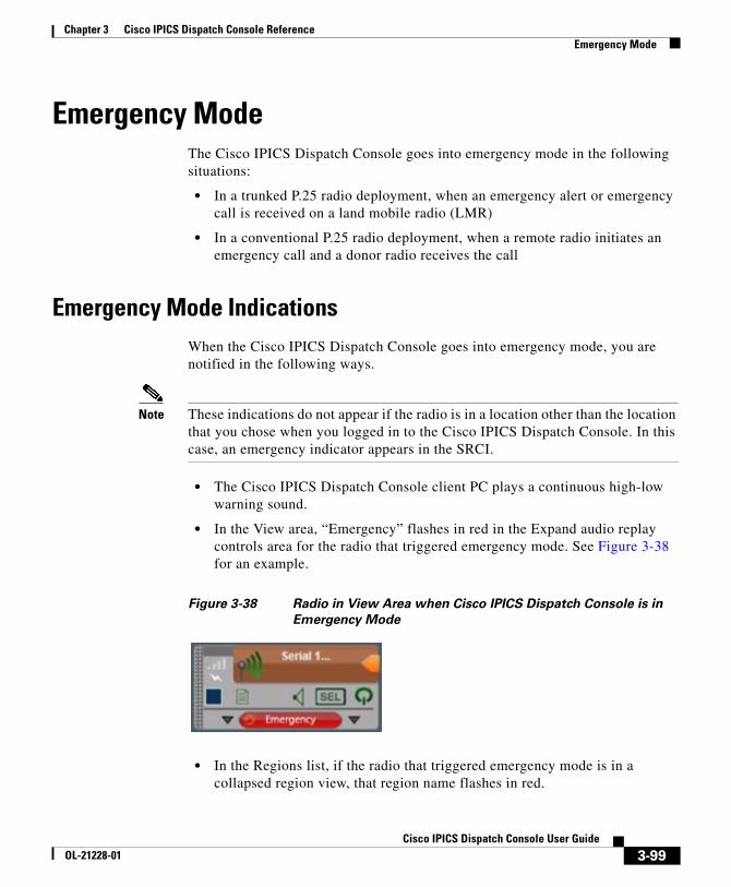
Chapter 3 Cisco IPICS Dispatch Console ReferenceEmergency Mode
Emergency ModeThe Cisco IPICS Dispatch Console goes into emergency mode in the following situations:
• In a trunked P.25 radio deployment, when an emergency alert or emergency call is received on a land mobile radio (LMR)
• In a conventional P.25 radio deployment, when a remote radio initiates an emergency call and a donor radio receives the call
Emergency Mode IndicationsWhen the Cisco IPICS Dispatch Console goes into emergency mode, you are notified in the following ways.
Note These indications do not appear if the radio is in a location other than the location that you chose when you logged in to the Cisco IPICS Dispatch Console. In this case, an emergency indicator appears in the SRCI.
• The Cisco IPICS Dispatch Console client PC plays a continuous high-low warning sound.
• In the View area, “Emergency” flashes in red in the Expand audio replay controls area for the radio that triggered emergency mode. See Figure 3-38 for an example.
Figure 3-38 Radio in View Area when Cisco IPICS Dispatch Console is in
Emergency Mode
• In the Regions list, if the radio that triggered emergency mode is in a collapsed region view, that region name flashes in red.
3-99Cisco IPICS Dispatch Console User Guide
OL-21228-01
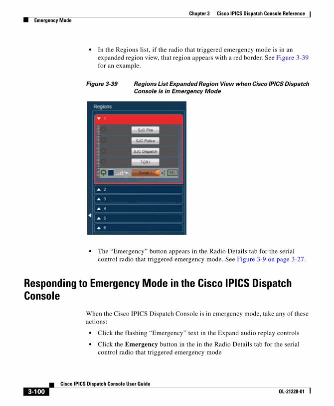
Chapter 3 Cisco IPICS Dispatch Console ReferenceEmergency Mode
• In the Regions list, if the radio that triggered emergency mode is in an expanded region view, that region appears with a red border. See Figure 3-39 for an example.
Figure 3-39 Regions List Expanded Region View when Cisco IPICS Dispatch
Console is in Emergency Mode
• The “Emergency” button appears in the Radio Details tab for the serial control radio that triggered emergency mode. See Figure 3-9 on page 3-27.
Responding to Emergency Mode in the Cisco IPICS Dispatch Console
When the Cisco IPICS Dispatch Console is in emergency mode, take any of these actions:
• Click the flashing “Emergency” text in the Expand audio replay controls
• Click the Emergency button in the in the Radio Details tab for the serial control radio that triggered emergency mode
3-100Cisco IPICS Dispatch Console User Guide
OL-21228-01
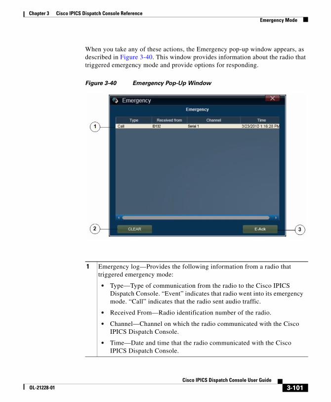
Chapter 3 Cisco IPICS Dispatch Console ReferenceEmergency Mode
When you take any of these actions, the Emergency pop-up window appears, as described in Figure 3-40. This window provides information about the radio that triggered emergency mode and provide options for responding.
Figure 3-40 Emergency Pop-Up Window
1 Emergency log—Provides the following information from a radio that triggered emergency mode:
• Type—Type of communication from the radio to the Cisco IPICS Dispatch Console. “Event” indicates that radio went into its emergency mode. “Call” indicates that the radio sent audio traffic.
• Received From—Radio identification number of the radio.
• Channel—Channel on which the radio communicated with the Cisco IPICS Dispatch Console.
• Time—Date and time that the radio communicated with the Cisco IPICS Dispatch Console.
3-101Cisco IPICS Dispatch Console User Guide
OL-21228-01
Chapter 3 Cisco IPICS Dispatch Console ReferenceEmergency Mode
Responding to Emergency Mode in the SRCIWhen the SRCI indicates that emergency mode is in effect, take the following actions.
Note To display, go to the Radio Details tab for the serial controlled radio that triggered the emergency mode and click the Ctrl button.
1. Click the Emergency button, which provides the following information from the radio that triggered emergency mode:
– Type—Type of communication from the radio to the Cisco IPICS Dispatch Console. “Event” indicates that radio went into its emergency mode. “Call” indicates that the radio sent audio traffic.
– Received From—Radio identification number of the radio.
– Channel—Channel on which the radio communicated with the Cisco IPICS Dispatch Console.
– Time—Date and time that the radio communicated with the Cisco IPICS Dispatch Console.
2. Click the Clear button when the emergency is addressed or resolved to remove the emergency notification in the SRCI.
2 Clear button—Click this button when the emergency is addressed or resolved to remove the information in the Emergency pop-up window and remove the emergency notifications in the Cisco IPICS Dispatch Console.
3 E-Ack button—Click this button to acknowledge the emergency. This action stops the high/low warning sound on your Cisco IPICS Dispatch Console and on Cisco IPICS Dispatch Consoles that are communicating via multicast.
3-102Cisco IPICS Dispatch Console User Guide
OL-21228-01
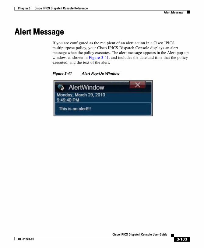
Chapter 3 Cisco IPICS Dispatch Console ReferenceAlert Message
Alert MessageIf you are configured as the recipient of an alert action in a Cisco IPICS multipurpose policy, your Cisco IPICS Dispatch Console displays an alert message when the policy executes. The alert message appears in the Alert pop-up window, as shown in Figure 3-41, and includes the date and time that the policy executed, and the text of the alert.
Figure 3-41 Alert Pop-Up Window
3-103Cisco IPICS Dispatch Console User Guide
OL-21228-01

Chapter 3 Cisco IPICS Dispatch Console ReferenceAlert Message
3-104Cisco IPICS Dispatch Console User Guide
OL-21228-01
CiscoOL-21228-01
I N D E X
A
account lockout 2-12
acknowledging, emergency mode 3-102
Activate Incident VTG button 3-43
Activate VTG button 3-37
activating
incident VTG 3-43
policy 3-86
VTG 3-37
Add a Channel pop-up window 3-60
Add an Image pop-up window 3-68
Add a Radio pop-up window 3-66
Add a User pop-up window 3-62
Add a Video pop-up window 3-70
Add a VTG pop-up window 3-65
adding 3-81, 3-84
channel to incident 3-60
channel to VTG 3-60
image to incident 3-68
incident 3-84
incident resource 3-45
radio to incident 3-66
radio to VTG 3-66
resource to incident 3-60
resource to VTG 3-60
user to incident 3-62
user to VTG 3-62
video to incident 3-70
VTG 3-81
VTG resource 3-40
VTG to incident 3-65
VTG to VTG 3-65
alert
configured tones for 3-93
from IPICS Connect 3-35
message 3-103
Alert pop-up window 3-103
alert tone
downloading 2-2
select channel for 3-12
select incident for 3-20
select radio for 3-14
select resource for 3-92, 3-98
select VTG for 3-17
All Mute button 3-92
All role, IPICS Dispatch Console features available to 1-8
IN-1 IPICS Dispatch Console User Guide
Index
all talk
select channel for 3-12
select incident for 3-20
select radio for 3-14
select resource for 3-92, 3-98
select VTG for 3-17
All Talk and Patch Controls area
hiding 3-93
location 3-92
showing 3-93
All Talk PTT button 3-93
audio
device for output 3-54
input devices 3-55
master controls 3-91
time received 3-98
volume 3-21, 3-77, 3-92
audio connections options 3-54
audio replay
channel 3-11
controls 3-20
description 3-20
hiding controls 3-11, 3-13, 3-16, 3-19, 3-21
incident 3-19
radio 3-13
save audio 3-22
showing controls 3-11, 3-13, 3-16, 3-19
VTG 3-16
IN-2Cisco IPICS Dispatch Console User Guide
audio select
channel 3-11
incident 3-19
radio 3-14
resource 3-98
VTG 3-16
Authentication.log log file 2-9
C
call
from IPICS connect 3-34
placing 3-90
Call button 3-89
channel
adding
to incident 3-60
to VTG 3-60
audio replay 3-11
audio select 3-11
icon 3-9
incidents participating in 3-11
latch 3-10
move 3-11
mute 3-11
name 3-9
on radio 3-24, 3-29
patch 3-11
powered on 3-9
OL-21228-01
Index
PTT 3-10
receive indicator 3-12
secure 3-9
traffic 3-12
transmit indicator 3-12
ChannelActivity.log log file 2-10
Cisco IPICS role, IPICS Dispatch Console features available to 1-8
Cisco IPICS server
downloading installation program from 2-3
IP address of 3-54
Cisco Security Agent (CSA 1-2
clearing emergency mode 3-102
client PC
audio devices on 3-55
description 1-2
guidelines 1-2
network interface card (NIC) 3-59
time on 3-91
connectivity, guidelines 2-11
Ctrl button, for serial control radio 3-26
D
dark theme 3-53
Deactivate Incident VTG button 3-43
Deactivate VTG button 3-37
deactivating
incident VTG 3-43
OL-21228-01
VTG 3-37
DebugLog.Txt log file 2-10
Dial button, in VTG 3-38
dial-out action, in VTG 3-38
Dial Pad and Channel Patch area
access to 1-8
displaying 3-86
hiding 3-87
showing 3-87
direct connect number, for IPICS Connect 3-33
Dispatcher role, IPICS Dispatch Console features available to 1-8
downloading
alert tone 2-2
IPICS Dispatch Console 2-3
DTMF button 3-94
E
Emergency button 3-29
emergency log 3-101
emergency mode
acknowledging 3-102
clearing 3-102
description 3-99
indications 3-99
IPICS Dispatch Console 3-99
responding to
from Cisco IPICS Dispatch Console 3-100
IN-3Cisco IPICS Dispatch Console User Guide
Index
from SRCI 3-102
serial control radio 3-32
Emergency pop-up window 3-101
encryption, for radio 3-25
Event Log tab 3-45
F
features, available to user 1-8
File menu 3-4
filtering
incident resource 3-45
VTG resource 3-40
G
group alias, for IPICS Connect 3-33
H
headset
audible hum 2-16
audio settings for 2-17
connecting to client PC 2-16
type 2-16
USB DSP 2-14
Help menu 3-5
hiding
All Talk and Patch Controls area 3-93
IN-4Cisco IPICS Dispatch Console User Guide
Dial Pad and Channel Patch area 3-87
Items Tabs area 3-79
Master Audio Controls area 3-91
System Information area 3-90
high availability (HA)
description 1-9
operation 1-10
Hld button 3-89
hot keys, assigning 3-57
I
icon
channel 3-9
incident 3-18
radio 3-12
VTG 3-15
IDC
See IPICS Dispatch Console
IDCTrace.txt log file 2-9
image
adding to incident 3-68
in incident 3-44
uploading to Cisco IPICS server 3-72
viewing 3-44
incident 3-84
active 1-9
adding
image to 3-68
OL-21228-01
Index
radio to 3-66
user to 3-62
video to 3-70
adding channel to 3-60
adding VTG to 3-65
audio replay 3-19
audio select 3-19
creating 3-84
description 1-8, 3-43
icon 3-18
inactive 1-9
latch 3-19, 3-43
listen only 3-43
move 3-20
mute 3-19
name 3-18
overview 1-8
patch 3-20
powered on 3-17
PTT 3-18
receive indicator 3-20
resource
adding 3-45
filtering 3-45
removing 3-45
status 3-44
types 3-44
RX mute 3-43
title 3-43
OL-21228-01
traffic 3-20
transmit indicator 3-20
VAD 3-43
Incident Details tab
displaying 3-19, 3-40, 3-84
Incidents tab
access to 1-6
items on 3-81
incident VTG
activating 3-43
deactivating 3-43
description 1-9, 3-41
state 3-42
installation directories, required privileges 2-2
installation program, downloading 2-3
installing, IPICS Dispatch Console 2-4
IPICS Connect
accessing 3-29
alert 3-35
call 3-34
direct connect number 3-33
group alias 3-33
page 3-35
IPICS Connect tab 3-32
IPICS Dispatch Console
color theme 3-53
emergency mode 3-99
exiting 1-5
features available by user type 1-8
IN-5Cisco IPICS Dispatch Console User Guide
Index
high availability (HA) 1-10
installation
directories 2-2
guidelines 2-2
procedure 2-4
installation program 2-3
installation program, downloading 2-3
keep on top 3-54
license types 1-6
log files 2-8
logging in to 1-3
logging out of 1-5
Main window 3-2
menu bar 3-4
off-line mode 1-7, 3-91
on-line mode 1-6, 3-91
operating mode 1-6, 3-91
overview 1-1
Platinum user license 1-6
Region tab 3-6
repairing 2-7
Silver user license 1-6
starting 1-3
themes 3-52, 3-53
uninstalling 2-6
upgrades 1-10
version 3-5
Items Tabs area 3-79
hiding 3-79
IN-6Cisco IPICS Dispatch Console User Guide
showing 3-79
K
Keep on Top check box 3-54
key assignments 3-57
L
last call transmit 3-98
latch
channel 3-10
incident 3-19, 3-43
radio 3-13
resource 3-98
VTG 3-16, 3-37
Latch button
channel 3-10
incident 3-19
radio 3-13
resource 3-98
VTG 3-16
license
Platinum 1-6
Silver 1-6
light theme 3-53
listen only
incident 3-43
VTG 3-37
OL-21228-01
Index
log file
Authentication.log 2-9
ChannelActivity.log 2-10
DebugLog.Txt 2-10
IDCTrace.txt 2-9
uploading to Cisco IPICS server 2-10
log in, to IPICS Dispatch Console 1-3
log out, of IPICS Dispatch Console 1-5
M
Main window 3-2
Master Audio Controls area
hiding 3-91
location 3-91
showing 3-91
Master Volume slider 3-92
menu bar 3-4
microphone
type 2-16
using with IPICS Dispatch Console 2-15
miscellaneous options 3-53
monitor, radio 3-25, 3-30
move
incident 3-20
resource 3-7, 3-8, 3-95, 3-98
mute
all 3-92
channel 3-11
OL-21228-01
incident 3-19
radio 3-14
resource 3-97
VTG 3-16
Mute button
channel 3-11
global 3-92
incident 3-19
radio 3-14
resource 3-97
VTG 3-16
N
name
incident 3-18
radio 3-24, 3-28
VTG 3-15
network interface card (NIC), selecting 3-59
network settings 3-59
network time protocol (NTP) server 1-2
notification action, in VTG 3-38
Notify button 3-38
O
off-line mode 1-7, 3-91
on-line mode 1-6, 3-91
IN-7Cisco IPICS Dispatch Console User Guide
Index
P
page, from IPICS Connect 3-35
password expiration 2-12
patch
incident 3-20
in Dial Pad and Channel Patch area 3-90
radio 3-14
resources 3-94
select channel for 3-12
select incident for 3-20
select radio for 3-14
select resource for 3-92, 3-98
select VTG for 3-17
VTG 3-17
Patch button 3-94
Platinum user license 1-6
Policies tab 3-85
policy
activating 3-86
alert message 3-103
Policy Execution Status tab
description 3-48
displaying 3-48
powered-off resource 3-8
powered-on
channel 3-9
incident 3-17
radio 3-12
IN-8Cisco IPICS Dispatch Console User Guide
resource 3-8
VTG 3-15
powering off
resource 3-96
powering on, resource 3-96
power level, radio 3-25, 3-31
primary Cisco IPICS server 1-10
PTT
all talk 3-93
channel 3-10
incident 3-18
radio 3-13, 3-24, 3-28
resource 3-97
VTG 3-15
push-to-talk
See PTT
R
radio
adding
to incident 3-66
to VTG 3-66
audio replay 3-13
audio select 3-14
icon 3-12
incidents participating in 3-14
latch 3-13
move 3-14
OL-21228-01
Index
mute 3-14
name 3-12
patch 3-14
powered on 3-12
PTT 3-13
receive indicator 3-14
secure 3-12
serial control
channels available 3-29
Ctrl button 3-26
Emergency button 3-29
emergency mode 3-32
monitor 3-30
name 3-28
power level 3-31
PTT 3-28
receive indicator 3-32
releasing 3-29
repeater or talkaround (RTA) 3-30
reserving 3-28, 3-29
scan 3-28
status 3-32
traffic 3-32
transmit indicator 3-32
transmit mode 3-31
tone control
channels available 3-24
encryption 3-25
monitor 3-25
OL-21228-01
name 3-24
power level 3-25
PTT 3-24
receive indicator 3-25
scan 3-24
traffic 3-25
transmit indicator 3-25
traffic 3-14
transmit indicator 3-14
Radio Details tab
displaying 3-14
serial control radio 3-25
tone control radio 3-22
receive indicator
channel 3-12
incident 3-20
radio 3-14, 3-25, 3-32
resource 3-97
VTG 3-17
Records per Page field 3-54
region 3-7
Regions list
collapsed region view 3-96
displaying 3-94
expanded region view 3-95
hiding 3-94, 3-96
moving resources 3-95, 3-98
showing 3-94, 3-96
Region tab 3-6
IN-9Cisco IPICS Dispatch Console User Guide
Index
Release button 3-29
releasing, serial control radio 3-29
removing
incident resource 3-45
VTG resource 3-40
repairing, IPICS Dispatch Console 2-7
repeater or talkaround (RTA), radio 3-30
replay audio
See audio replay
Res button 3-89
Reserve button 3-29
reserving, serial control radio 3-28, 3-29
resource
adding
to incident 3-60
to VTG 3-60
adding to incident 3-45
adding to VTG 3-40
audio select 3-98
channel 3-9
icons 3-8
incident 3-17
in incident 3-44
in VTG 3-39
latch 3-98
move 3-8, 3-95, 3-98
mute 3-97
patching 3-94
IN-10Cisco IPICS Dispatch Console User Guide
power
off 3-8
on 3-8
powering off 3-96
powering on 3-96
power on 3-8
PTT 3-97
radio 3-12
receive indicator 3-97
removing from incident 3-45
removing from VTG 3-40
transmit indicator 3-98
VTG 3-15
role
All 1-8
Dispatcher 1-8
RunIDC.exe process 1-2
RX mute
incident 3-43
VTG 3-37
S
scan 3-24, 3-28
secondary Cisco IPICS server 1-10
secure
channel 3-9
radio 3-12
OL-21228-01
Index
select
channel, for all talk, patch, alert tone 3-12
incident, for all talk, patch, alert tone 3-20
radio, for all talk, patch, alert tone 3-14
resource, for all talk, patch, alert tone 3-92, 3-98
VTG, for all talk, patch, alert tone 3-17
Select check box
channel 3-12
incident 3-20
radio 3-14
resource 3-98
VTG 3-17
serial control radio, radio details tab 3-25
Serial Radio Control Interface (SRCI)
accessing 3-26
emergency mode 3-102
Server Address field 3-54
Settings tab
audio connections options 3-54
description 3-50
displaying 3-50
key assignments options 3-57
miscellaneous options 3-53
network settings options 3-59
themes options 3-52, 3-53
showing
All Talk and Patch Controls area 3-93
Dial Pad and Channel Patch area 3-87
Items Tabs area 3-79
OL-21228-01
Master Audio Controls area 3-91
Regions list 3-94, 3-96
System Information area 3-90
Show Rx Times check box 3-53
Silver user license 1-6
starting, IPICS Dispatch Console 1-3
state, of IPICS Dispatch Console 1-7, 3-91
status
of incident resource 3-44
of VTG resource 3-39
serial control radio 3-32
System Information area
hiding 3-90
location 3-90
showing 3-90
T
themes
dark 3-53
light 3-53
options 3-52, 3-53
time, on client PC 3-91
time stamp, for audio received 3-98
tone control radio
DTMF tones 3-94
Radio Details tab 3-22
traffic
channel 3-12
IN-11Cisco IPICS Dispatch Console User Guide
Index
incident 3-20
radio 3-14, 3-25, 3-32
VTG 3-17
transmit indicator
channel 3-12
incident 3-20
radio 3-14, 3-25, 3-32
resource 3-98
VTG 3-17
transmit mode, radio 3-31
U
uninstalling, IPICS Dispatch Console 2-6
Unmute button
channel 3-11
global 3-92
incident 3-19
radio 3-14
resource 3-97
VTG 3-16
Unpatch button 3-94
upgrades, IPICS Dispatch Console 1-10
Upload an Image pop-up window 3-72
Upload a Video pop-up window 3-74
uploading
image to Cisco IPICS server 3-72
video to Cisco IPICS server 3-74
USB DSP headset, using with IPICS Dispatch Console 2-14
IN-12Cisco IPICS Dispatch Console User Guide
user
adding to incident 3-62
adding to VTG 3-62
user, features available to 1-8
V
VAD
in incident 3-43
in VTG 3-37
video
adding to incident 3-70
format 3-75
in incident 3-44
type 3-70
uploading to Cisco IPICS server 3-74
viewing 3-44
YouTube 3-75, 3-78
View menu 3-4
VLC media player 1-2
Voice Activity Detection
See VAD
voice quality, guidelines 2-16
volume, audio 3-21, 3-77, 3-92
VTG 3-81
activating 3-37
adding
channel to 3-60
radio to 3-66
OL-21228-01
Index
to incident 3-65
to VTG 3-65
user to 3-62
VTG to 3-65
audio replay 3-16
audio select 3-16
creating 3-81
deactivating 3-37
description 3-37
dial-out 3-38
icon 3-15
latch 3-16, 3-37
listen only 3-37
move 3-17
mute 3-16
name 3-15
notification 3-38
patch 3-17
powered on 3-15
PTT 3-15
receive indicator 3-17
resource
adding 3-40
filtering 3-40
removing 3-40
status 3-39
types 3-39
RX mute 3-37
state 3-36
OL-21228-01
title 3-36
traffic 3-17
transmit indicator 3-17
VAD 3-37
VTG Details tab
displaying 3-17, 3-35, 3-81
features 3-35
VTGs tab
access to 1-6
items on 3-79
W
WaveEngine.exe process 1-2
WAVE Engine service
description 2-7
restarting 2-8
status, determining 2-7
trusting 1-2
Windows time service 1-2
Y
YouTube video
source URL for 3-75
viewing 3-78
IN-13Cisco IPICS Dispatch Console User Guide

Index
IN-14Cisco IPICS Dispatch Console User Guide
OL-21228-01