cisco nexus 9348gc-fxp aci mode hardware installation guide
TRANSCRIPT
Cisco Nexus 9348GC-FXP ACI Mode Hardware Installation GuideFirst Published: 2017-09-27
Last Modified: 2019-03-28
Americas HeadquartersCisco Systems, Inc.170 West Tasman DriveSan Jose, CA 95134-1706USAhttp://www.cisco.comTel: 408 526-4000
800 553-NETS (6387)Fax: 408 527-0883

THE SPECIFICATIONS AND INFORMATION REGARDING THE PRODUCTS REFERENCED IN THIS DOCUMENTATION ARE SUBJECT TO CHANGE WITHOUT NOTICE.EXCEPT AS MAY OTHERWISE BE AGREED BY CISCO IN WRITING, ALL STATEMENTS, INFORMATION, AND RECOMMENDATIONS IN THIS DOCUMENTATION AREPRESENTED WITHOUT WARRANTY OF ANY KIND, EXPRESS OR IMPLIED.
The Cisco End User License Agreement and any supplemental license terms govern your use of any Cisco software, including this product documentation, and are located at:http://www.cisco.com/go/softwareterms.Cisco product warranty information is available at http://www.cisco.com/go/warranty. US Federal Communications Commission Notices are foundhere http://www.cisco.com/c/en/us/products/us-fcc-notice.html.
IN NO EVENT SHALL CISCO OR ITS SUPPLIERS BE LIABLE FOR ANY INDIRECT, SPECIAL, CONSEQUENTIAL, OR INCIDENTAL DAMAGES, INCLUDING, WITHOUTLIMITATION, LOST PROFITS OR LOSS OR DAMAGE TO DATA ARISING OUT OF THE USE OR INABILITY TO USE THIS MANUAL, EVEN IF CISCO OR ITS SUPPLIERSHAVE BEEN ADVISED OF THE POSSIBILITY OF SUCH DAMAGES.
Any products and features described herein as in development or available at a future date remain in varying stages of development and will be offered on a when-and if-available basis. Anysuch product or feature roadmaps are subject to change at the sole discretion of Cisco and Cisco will have no liability for delay in the delivery or failure to deliver any products or featureroadmap items that may be set forth in this document.
Any Internet Protocol (IP) addresses and phone numbers used in this document are not intended to be actual addresses and phone numbers. Any examples, command display output, networktopology diagrams, and other figures included in the document are shown for illustrative purposes only. Any use of actual IP addresses or phone numbers in illustrative content is unintentionaland coincidental.
The documentation set for this product strives to use bias-free language. For the purposes of this documentation set, bias-free is defined as language that does not imply discrimination basedon age, disability, gender, racial identity, ethnic identity, sexual orientation, socioeconomic status, and intersectionality. Exceptions may be present in the documentation due to languagethat is hardcoded in the user interfaces of the product software, language used based on RFP documentation, or language that is used by a referenced third-party product.
Cisco and the Cisco logo are trademarks or registered trademarks of Cisco and/or its affiliates in the U.S. and other countries. To view a list of Cisco trademarks, go to this URL: www.cisco.comgo trademarks. Third-party trademarks mentioned are the property of their respective owners. The use of the word partner does not imply a partnership relationship between Cisco and anyother company. (1721R)
© 2017-2018 Cisco Systems, Inc. All rights reserved.
C O N T E N T S
Trademarks ?
Preface viiP R E F A C E
Audience vii
Documentation Conventions vii
Related Documentation viii
Documentation Feedback x
Obtaining Documentation and Submitting a Service Request x
Overview 1C H A P T E R 1
Overview 1
Preparing the Site 5C H A P T E R 2
Temperature Requirements 5
Humidity Requirements 5
Altitude Requirements 5
Dust and Particulate Requirements 6
Minimizing Electromagnetic and Radio Frequency Interference 6
Shock and Vibration Requirements 7
Grounding Requirements 7
Planning for Power Requirements 7
Airflow Requirements 9
Rack and Cabinet Requirements 9
Clearance Requirements 10
Installing the Switch Chassis 13C H A P T E R 3
Cisco Nexus 9348GC-FXP ACI Mode Hardware Installation Guideiii
Safety 13
Installation Options with Rack-Mount Kits 14
Airflow Considerations 14
Installation Guidelines 15
Unpacking and Inspecting the Switch 16
Installing the Switch Using the NXK-ACC-KIT-1RU Rack-Mount Kit 17
Installing the Switch Using the N3K-C3064-ACC-KIT Rack-Mount Kit 20
Installing the Switch into a Two-post Rack 24
Grounding the Chassis 27
Starting the Switch 29
Connecting the Switch to the ACI Fabric 31C H A P T E R 4
ACI Fabric Topology 31
Preparing to Connect to Other Devices 32
Connecting Leaf Switches to APICs 33
Connecting Leaf Switches to Spine Switches 35
Installing a Gigabit Ethernet module (GEM) 36
Virtual Port Channel Migration - Migration of Nodes from a First-Generation Switch to aSecond-Generation Switch 36
Setting Up an Optional Console Interface 37
Setting Up an Optional Management Connection 38
Optic Transceiver Removal Using the Optics Extraction Tool 39
Maintaining Transceivers and Optical Cables 40
Replacing Components 41C H A P T E R 5
Replacing a Fan Module 41
Removing a Fan Module 41
Installing a Fan Module 42
Replacing a Power Supply Module 42
Replacing an AC Power Supply 42
Replacing a High Voltage (HVAC/HVDC) Power Supply 43
Replacing a DC Power Supply 45
Wiring the DC Input Power Source 46
Cisco Nexus 9348GC-FXP ACI Mode Hardware Installation Guideiv
Contents
Rack Specifications 49A P P E N D I X A
Overview of Racks 49
General Requirements for Cabinets and Racks 49
Requirements Specific to Standard Open Racks 50
Requirements Specific to Perforated Cabinets 50
Cable Management Guidelines 51
System Specifications 53A P P E N D I X B
Environmental Specifications 53
Switch Dimensions 53
Switch and Module Weights and Quantities 54
Transceiver and Cable Specifications 54
Switch Power Input Requirements 54
Power Specifications 55
350-W AC Power Supply Specifications 55
350-W PHV Power Supply Specifications 56
440-W DC Power Supply Specifications 56
Power Cable Specifications 57
Power Cable Specifications for AC Power Supplies 57
DC Power Cable Specifications 58
Regulatory Standards Compliance Specifications 58
LEDs 61A P P E N D I X C
Switch Chassis LEDs 61
Fan Module LEDs 62
Power Supply LEDs 62
Additional Kits 65A P P E N D I X D
Rack Mount Kit for a Two-Post Rack 65
Rack Mount Kit NXK-ACC-KIT-1RU 65
Rack Mount Kit N3K-C3064-ACC-KIT 66
Site Preparation and Maintenance Records 69A P P E N D I X E
Cisco Nexus 9348GC-FXP ACI Mode Hardware Installation Guidev
Contents
Site Preparation Checklist 69
Contact and Site Information 70
Chassis and Module Information 71
Cisco Nexus 9348GC-FXP ACI Mode Hardware Installation Guidevi
Contents
Preface
• Audience, on page vii• Documentation Conventions, on page vii• Related Documentation, on page viii• Documentation Feedback, on page x• Obtaining Documentation and Submitting a Service Request , on page x
AudienceThis publication is for hardware installers and network administrators who install, configure, and maintainCisco Nexus switches.
Documentation ConventionsCommand descriptions use the following conventions:
DescriptionConventionBold text indicates the commands and keywords that you enter literallyas shown.
bold
Italic text indicates arguments for which the user supplies the values.Italic
Square brackets enclose an optional element (keyword or argument).[x]
Square brackets enclosing keywords or arguments separated by a verticalbar indicate an optional choice.
[x | y]
Braces enclosing keywords or arguments separated by a vertical barindicate a required choice.
{x | y}
Nested set of square brackets or braces indicate optional or requiredchoices within optional or required elements. Braces and a vertical barwithin square brackets indicate a required choice within an optionalelement.
[x {y | z}]
Indicates a variable for which you supply values, in context where italicscannot be used.
variable
Cisco Nexus 9348GC-FXP ACI Mode Hardware Installation Guidevii
DescriptionConvention
A nonquoted set of characters. Do not use quotation marks around thestring or the string will include the quotation marks.
string
Examples use the following conventions:
DescriptionConventionTerminal sessions and information the switch displays are in screen font.screen font
Information you must enter is in boldface screen font.boldface screen font
Arguments for which you supply values are in italic screen font.italic screen font
Nonprinting characters, such as passwords, are in angle brackets.< >
Default responses to system prompts are in square brackets.[ ]
An exclamation point (!) or a pound sign (#) at the beginning of a lineof code indicates a comment line.
!, #
Related DocumentationThe Application Centric Infrastructure documentation set includes the following documents that are availableon Cisco.com at the following URL:https://www.cisco.com/c/en/us/support/cloud-systems-management/application-policy-infrastructure-controller-apic/tsd-products-support-series-home.html.
Web-Based Documentation
• Cisco APIC Management Information Mode Reference
• Cisco APIC Online Help Reference
• Cisco APIC Python SDK Reference
• Cisco ACI Compatibility Tool
• Cisco ACI MIB Support List
Downloadable Documentation
• Knowledge Base Articles (KB Articles)are available at the following URL:https://www.cisco.com/c/en/us/support/cloud-systems-management/application-policy-infrastructure-controller-apic/products-configuration-examples-list.html
• Cisco Application Centric Infrastructure Controller Release Notes
• Cisco Application Centric Infrastructure Fundamentals Guide
• Cisco APIC Getting Started Guide
• Cisco ACI Virtualization Guide
• Cisco APIC REST API User Guide
• Cisco APIC Command Line Interface User Guide
Cisco Nexus 9348GC-FXP ACI Mode Hardware Installation Guideviii
PrefaceRelated Documentation

• Cisco APIC Faults, Events, and System Messages Management Guide
• Cisco ACI System Messages Reference Guide
• Cisco APIC Layer 4 to Layer 7 Services Deployment Guide
• Cisco APIC Layer 4 to Layer 7 Device Package Development Guide
• Cisco APIC Layer 4 to Layer 7 Device Package Test Guide
• Cisco ACI Firmware Management Guide
• Cisco ACI Troubleshooting Guide
• Cisco ACI Switch Command Reference, NX-OS Release 11.0
• Cisco Verified Scalability Guide for Cisco ACI
• Cisco ACI MIB Quick Reference
• Cisco Nexus CLI to Cisco APIC Mapping Guide
• Application Centric Inftrastructure Fabric Hardware Installation Guide
• Cisco NX-OS Release Notes for Cisco Nexus 9000 Series ACI-Mode Switches
• Cisco Nexus 9000 Series ACI Mode Licensing Guide
• Cisco Nexus 93108TX-EX ACI-Mode Switch Hardware Installation Guide
• Cisco Nexus 93108TX-FX ACI-Mode Switch Hardware Installation Guide
• Cisco Nexus 93120TX ACI-Mode Switch Hardware Installation Guide
• Cisco Nexus 93128TX ACI-Mode Switch Hardware Installation Guide
• Cisco Nexus 93180LC-EX ACI-Mode Switch Hardware Installation Guide
• Cisco Nexus 93180YC-EX ACI-Mode Switch Hardware Installation Guide
• Cisco Nexus 93180YC-FX ACI-Mode Switch Hardware Installation Guide
• Cisco Nexus 9332PQ ACI-Mode Switch Hardware Installation Guide
• Cisco Nexus 9336PQ ACI-Mode Switch Hardware Installation Guide
• Cisco Nexus 9348GC-FXP ACI-Mode Switch Hardware Installation Guide
• Cisco Nexus 9364C ACI-Mode Switch Hardware Installation Guide
• Cisco Nexus 9372PX and 9372PX-E ACI-Mode Switches Hardware Installation Guide
• Cisco Nexus 9372TX and 9372TX-E ACI-Mode Switches Hardware Installation Guide
• Cisco Nexus 9396PX ACI-Mode Switch Hardware Installation Guide
• Cisco Nexus 9396TX ACI-Mode Switch Hardware Installation Guide
• Cisco Nexus 9504 ACI-Mode Switch Hardware Installation Guide
• Cisco Nexus 9508 ACI-Mode Switch Hardware Installation Guide
• Cisco Nexus 9516 ACI-Mode Switch Hardware Installation Guide
Cisco Nexus 9348GC-FXP ACI Mode Hardware Installation Guideix
PrefacePreface
Cisco Application Centric Infrastructure (ACI) Simulator Documentation
The following Cisco ACI Simulator documentation is available athttps://www.cisco.com/c/en/us/support/cloud-systems-management/application-centric-infrastructure-simulator/tsd-products-support-series-home.html.
• Cisco ACI Simulator Release Notes
• Cisco ACI Simulator Installation Guide
• Cisco ACI Simulator Getting Started Guide
Cisco Nexus 9000 Series Switches Documentation
The Cisco Nexus 9000 Series Switches documentation is available athttps://www.cisco.com/c/en/us/support/switches/nexus-9000-series-switches/tsd-products-support-series-home.html.
Cisco Application Virtual Switch Documentation
The Cisco Application Virtual Switch (AVS) documentation is available athttps://www.cisco.com/c/en/us/support/switches/application-virtual-switch/tsd-products-support-series-home.html.
Documentation FeedbackTo provide technical feedback on this document, or to report an error or omission, please send your commentsto [email protected]. We appreciate your feedback.
Obtaining Documentation and Submitting a Service RequestFor information on obtaining documentation, using the Cisco Bug Search Tool (BST), submitting a servicerequest, and gathering additional information, see What's New in Cisco Product Documentation, at:https://www.cisco.com/warp/public/687/Directory/DirTAC.shtml.
Subscribe to What's New in Cisco Product Documentation, which lists all new and revised Cisco technicaldocumentation as an RSS feed and delivers content directly to your desktop using a reader application. TheRSS feeds are a free service.
Cisco Nexus 9348GC-FXP ACI Mode Hardware Installation Guidex
PrefaceDocumentation Feedback
C H A P T E R 1Overview
• Overview, on page 1
OverviewThe Cisco Nexus 9348GC-FXP switch (N9K-C9348GC-FXP) is a 1-RU fixed-port, L2/L3 switch, designedfor ACI deployments. This switch has 48 10/100/1000-Megabit 1GBASE-T host ports, 4 1/10-/25-GigabitSFP28 host ports, and 2 40-/100-Gigabit QSFP28 uplink ports.
Autonegotiation is supported on 100M/1G/10G ports.Note
The chassis for this switch includes the following user-replaceable components:
• Fan modules (three) with the following airflow choices:
• Port-side intake airflow with burgundy coloring (NXA-FAN-30CFM-B)
• Port-side exhaust airflow with blue coloring (NXA-FAN-30CFM-F)
Table 1: Fan Speeds for this Switch
Port-Side Exhaust
Fan Speed %
Port-Side Intake
Fan Speed %
70%50%Typical/Minimum
100%100%Maximum
Note
• Power supply modules (two—one for operations and one for redundancy [1+1]) with the followingchoices (do not mix AC and DC power sources and do not mix airflow directions):
• 350-W AC power supply with port-side intake airflow (burgundy coloring) (NXA-PAC-350W-PI)
• 350-W AC power supply with port-side exhaust airflow (blue coloring) (NXA-PAC-350W-PE)
Cisco Nexus 9348GC-FXP ACI Mode Hardware Installation Guide1
• 350-W HVAC/HVDC power supply with port-side intake airflow (blue coloring)(NXA-PHV-350W-PI)
• 350-W HVAC/HVDC power supply with port-side exhaust airflow (blue coloring)(NXA-PHV-350W-PE)
• 440-WDC power supply with port-side exhaust airflow (burgundy coloring) (NXA-PDC-440W-PI)
• 440-W DC power supply with port-side exhaust airflow (blue coloring) (NXA-PDC-440W-PE)
The 350-W AC power supply does not have the standby voltage tobe able to carry to a second power supply, to allow it to communicateand poll the device.
Note
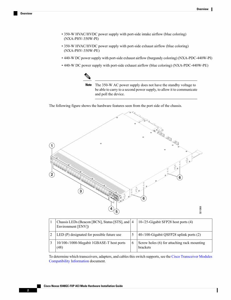
The following figure shows the hardware features seen from the port side of the chassis.
10-/25-Gigabit SFP28 host ports (4)4Chassis LEDs (Beacon [BCN], Status [STS], andEnvironment [ENV])
1
40-/100-Gigabit QSFP28 uplink ports (2)5LED (P) designated for possible future use2
Screw holes (6) for attaching rack mountingbrackets
610/100-/1000-Megabit 1GBASE-T host ports(48)
3
To determine which transceivers, adapters, and cables this switch supports, see the Cisco Transceiver ModulesCompatibility Information document.
Cisco Nexus 9348GC-FXP ACI Mode Hardware Installation Guide2
OverviewOverview
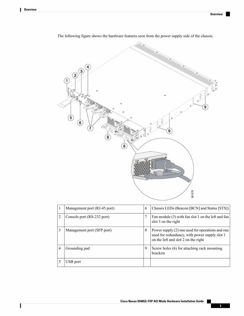
The following figure shows the hardware features seen from the power supply side of the chassis.
Chassis LEDs (Beacon [BCN] and Status [STS])6Management port (RJ-45 port)1
Fan module (3) with fan slot 1 on the left and fanslot 3 on the right
7Console port (RS-232 port)2
Power supply (2) one used for operations and oneused for redundancy, with power supply slot 1on the left and slot 2 on the right
8Management port (SFP port)3
Screw holes (6) for attaching rack mountingbrackets
9Grounding pad4
USB port5
Cisco Nexus 9348GC-FXP ACI Mode Hardware Installation Guide3
OverviewOverview

USB support is limited to USB 2.0 devices that use less than 2.5W (less than 0.5 A inclusive of surge current).Devices, such as external hard drives, that instantaneously draw more than 0.5 A are not supported.
Note
Depending on whether you plan to position the ports in a hot or cold aisle, you can order the fan and powersupply modules with port-side intake or port-side exhaust airflow. To determine the airflow direction of themodules installed in your switch, see the following table.
Port-Side Exhaust Airflow ColoringPort-Side Intake Airflow ColoringReplaceable Modules
BlueBurgundyFans
BlueBurgundyAC power supplies
The fan and power supply modules are field replaceable. You can replace one fan module or one power supplymodule during operations, so long as the other modules are installed and operating. If you have only onepower supply installed, you can install the replacement power supply in the open slot before removing theoriginal power supply.
All of the fan and power supply modules must have the same direction of airflow. Otherwise, the switch canoverheat and shut down. If you are installing a dual-direction power supply, that module automatically usesthe same airflow direction as the other modules in the switch.
Note
If the switch has port-side intake airflow (burgundy coloring for fan modules), you must locate the ports inthe cold aisle. If the switch has port-side exhaust airflow (blue coloring for fan modules), you must locate theports in the hot aisle. If you locate the air intake in a hot aisle, the switch can overheat and shut down.
Caution
Cisco Nexus 9348GC-FXP ACI Mode Hardware Installation Guide4
OverviewOverview
C H A P T E R 2Preparing the Site
• Temperature Requirements, on page 5• Humidity Requirements, on page 5• Altitude Requirements, on page 5• Dust and Particulate Requirements, on page 6• Minimizing Electromagnetic and Radio Frequency Interference, on page 6• Shock and Vibration Requirements, on page 7• Grounding Requirements, on page 7• Planning for Power Requirements, on page 7• Airflow Requirements, on page 9• Rack and Cabinet Requirements, on page 9• Clearance Requirements, on page 10
Temperature RequirementsThe switch requires an operating temperature of 32 to 104 degrees Fahrenheit (0 to 40 degrees Celsius). Ifthe switch is not operating, the temperature must be between –40 to 158 degrees Fahrenheit (–40 to 70 degreesCelsius).
Humidity RequirementsHigh humidity can cause moisture to enter the switch. Moisture can cause corrosion of internal componentsand degradation of properties such as electrical resistance, thermal conductivity, physical strength, and size.The switch is rated to withstand from 5- to 95-percent (noncondensing) relative humidity.
Buildings in which the climate is controlled by air-conditioning in the warmer months and by heat during thecolder months usually maintain an acceptable level of humidity for the switch equipment. However, if theswitch is located in an unusually humid location, use a dehumidifier to maintain the humidity within anacceptable range.
Altitude RequirementsAltitude rating is based on power supply installed; see critical components list in the system CB report foraltitude rating.
Cisco Nexus 9348GC-FXP ACI Mode Hardware Installation Guide5

Dust and Particulate RequirementsExhaust fans cool power supplies and system fans cool switches by drawing in air and exhausting air outthrough various openings in the chassis. However, fans also ingest dust and other particles, causing contaminantbuildup in the switch and increased internal chassis temperature. Dust and particles can act as insulators andinterfere with the mechanical components in the switch. A clean operating environment can greatly reducethe negative effects of dust and other particles.
In addition to keeping your environment free of dust and particles, follow these precautions to avoidcontamination of your switch:
• Do not permit smoking near the switch.
• Do not permit food or drink near the switch.
Minimizing Electromagnetic and Radio Frequency InterferenceElectromagnetic interference (EMI) and radio frequency interference (RFI) from the switch can adverselyaffect other devices, such as radio and television (TV) receivers. Radio frequencies that emanate from theswitch can also interfere with cordless and low-power telephones. Conversely, RFI from high-power telephonescan cause spurious characters to appear on the switch monitor.
RFI is defined as any EMI with a frequency above 10 kHz. This type of interference can travel from the switchto other devices through the power cable and power source or through the air as transmitted radio waves. TheFederal Communications Commission (FCC) publishes specific regulations to limit the amount of EMI andRFI that are emitted by computing equipment. Each switch meets these FCC regulations.
To reduce the possibility of EMI and RFI, follow these guidelines:
• Cover all open expansion slots with a blank filler plate.
• Always use shielded cables with metal connector shells for attaching peripherals to the switch.
When wires are run for any significant distance in an electromagnetic field, interference can occur to thesignals on the wires with the following implications:
• Bad wiring can result in radio interference emanating from the plant wiring.
• Strong EMI, especially when it is caused by lightning or radio transmitters, can destroy the signal driversand receivers in the chassis and even create an electrical hazard by conducting power surges throughlines into equipment.
To predict and prevent strong EMI, you need to consult experts in radio frequency interference (RFI).Note
The wiring is unlikely to emit radio interference if you use a twisted-pair cable with a good distribution ofgrounding conductors. If you exceed the recommended distances, use a high-quality twisted-pair cable withone ground conductor for each data signal when applicable.
Cisco Nexus 9348GC-FXP ACI Mode Hardware Installation Guide6
Preparing the SiteDust and Particulate Requirements
If the wires exceed the recommended distances, or if wires pass between buildings, give special considerationto the effect of a lightning strike in your vicinity. The electromagnetic pulse that is caused by lightning orother high-energy phenomena can easily couple enough energy into unshielded conductors to destroy electronicswitches. You will want to consult experts in electrical surge suppression and shielding if you had similarproblems in the past.
Caution
Shock and Vibration RequirementsThe switch has been shock- and vibration-tested for operating ranges, handling, and earthquake standards.
Grounding RequirementsThe switch is sensitive to variations in voltage that is supplied by the power sources. Overvoltage, undervoltage,and transients (or spikes) can erase data from memory or cause components to fail. To protect against thesetypes of problems, ensure that there is an earth-ground connection for the switch. You can connect the groundingpad on the switch either directly to the earth-ground connection or to a fully bonded and grounded rack.
When you properly install the chassis in a grounded rack, the switch is grounded because it has a metal-to-metalconnection to the rack. Alternatively, you can ground the chassis by using a customer-supplied groundingcable that meets your local and national installation requirements. For U.S. installations, we recommend6-AWG wire. Connect your grounding cable to the chassis with a grounding lug (provided in the switchaccessory kit) and to the facility ground.
You automatically ground AC power supplies when you connect them to AC power sources. For DC powersupplies, you must connect a grounding wire when wiring the power supply to the DC power source.
Note
An electrical conducting path shall exist between the product chassis and the metal surface of the enclosureor rack in which it is mounted or to a grounding conductor. Electrical continuity shall be provided by usingthread-forming type mounting screws that remove any paint or non-conductive coatings and establish ametal-to-metal contact. Any paint or other non-conductive coatings shall be removed on the surfaces betweenthe mounting hardware and the enclosure or rack. The surfaces shall be cleaned and an antioxidant appliedbefore installation.
Note
Planning for Power RequirementsThe switch includes two power supplies (1-to-1 redundancy with current sharing) in one of the followingcombinations:
• Two 350-W AC power supplies
• Two 440-W DC power supplies
Cisco Nexus 9348GC-FXP ACI Mode Hardware Installation Guide7
Preparing the SiteShock and Vibration Requirements

For n+1 redundancy, you can use one or two power sources for the two power supplies. For n+n redundancy,you must use two power sources and connect each power supply to a separate power source.
Note
The power supplies are rated to output up to 350W (AC power supplies) or up to 440W (DC power supplies),but the switch requires less than those amounts of power from the power supply. To operate the switch, youmust provision enough power from the power source to cover the requirements of both the switch and a powersupply. Typically, this switch and a power supply require about 200 W of power input from the power source,but you must provision as much as 443 W power input from the power source to cover peak demand.
Some of the power supply modules have rating capabilities that exceed the switch requirements. Whencalculating your power requirements, use the switch requirements to determine the amount of power that isrequired for the power supplies.
Note
To minimize the possibility of circuit failure, make sure that each power-source circuit that is used by theswitch is dedicated to the switch.
For AC input application, please refer to the following statement:Note
Statement 1005—Circuit Breaker when using AC power supplies
This product relies on the building's installation for short-circuit (overcurrent) protection. Ensure that theprotective devices are rated not greater than 20A (North America), 16A (Europe), and 13A (UK).
Warning
For DC input application, please refer to the following statement:Note
Statement 1005—Circuit Breaker when using DC power supplies
This product relies on the building's installation for short-circuit (overcurrent) protection.
• Ensure that the protective devices are rated not greater than 30Awhen the switch is powered with regularDC power supplies (rated 48-60VDC).
• Ensure that the protective devices are rated not greater than 10Awhen the switch is powered with HVDCpower supplies (rated 240-350VDC).
Warning
Statement 1033
Connect the unit only to DC power source that complies with the Safety Extra-Low Voltage (SELV)requirements in IEC 60950 based safety standards.
Warning
Cisco Nexus 9348GC-FXP ACI Mode Hardware Installation Guide8
Preparing the SitePlanning for Power Requirements
We recommend 8-AWG wire for DC installations in the U.S.Note
For the power cables to use with the power supplies, see Power Cable Specifications, on page 57.Note
Airflow RequirementsThe switch is positioned with its ports in either the front or the rear of the rack depending on your cablingand maintenance requirements. You must have fan and power supply modules that move the coolant air fromthe cold aisle to the hot aisle in one of the following ways:
• Port-side exhaust airflow—Cool air enters the chassis through the fan and power supply modules in thecold aisle and exhausts through the port end of the chassis in the hot aisle.
• Port-side intake airflow—Cool air enters the chassis through the port end in the cold aisle and exhauststhrough the fan and power supply modules in the hot aisle.
You can identify the airflow direction of each fan and power supply module by its coloring as follows:
• Blue coloring indicates port-side exhaust airflow.
• Burgundy coloring indicates port-side intake airflow.
• White coloring on HVAC/HVDC power supplies indicates dual-direction airflow.
To prevent the switch from overheating and shutting down, you must position the air intake for the switch ina cold aisle. The fan and power supply modules must have the same direction of airflow (even if their coloringis different). If you must change the airflow direction for the switch, you must shutdown the switch beforechanging the modules.
Note
Rack and Cabinet RequirementsYou can install the following types of racks or cabinets for your switch:
• Standard perforated cabinets
• Solid-walled cabinets with a roof fan tray (bottom-to-top cooling)
• Standard open four-post Telco racks
Work with your cabinet vendors to determine which of their cabinets meet the following requirements or seethe Cisco Technical Assistance Center (TAC) for recommendations:
Cisco Nexus 9348GC-FXP ACI Mode Hardware Installation Guide9
Preparing the SiteAirflow Requirements
• Use a standard 19-inch (48.3-cm), four-post Electronic Industries Alliance (EIA) cabinet or rack withmounting rails that conform to English universal hole spacing per section 1 of the ANSI/EIA-310-D-1992standard.
• The depth of a four-post rack must be 24 to 32 inches (61.0 to 81.3 cm) between the front and rearmounting rails (for proper mounting of the bottom-support brackets or other mounting hardware).
• Required clearances between the chassis and the edges of its rack or the interior of its cabinet are asfollows:
• 4.5 inches (11.4 cm) between the front of the chassis and the interior of the cabinet (required forcabling).
• 3.0 inches (7.6 cm) between the rear of the chassis and the interior of the cabinet (required for airflowin the cabinet if used).
• No clearance is required between the chassis and the sides of the rack or cabinet (no side airflow).
Also, you must have power receptacles that are located within reach of the power cords that are used with theswitch.
Statement 1048—Rack Stabilization
The rack stabilizing mechanism must be in place, or the rack must be bolted to the floor before installationor servicing. Failure to stabilize the rack can cause bodily injury.
Warning
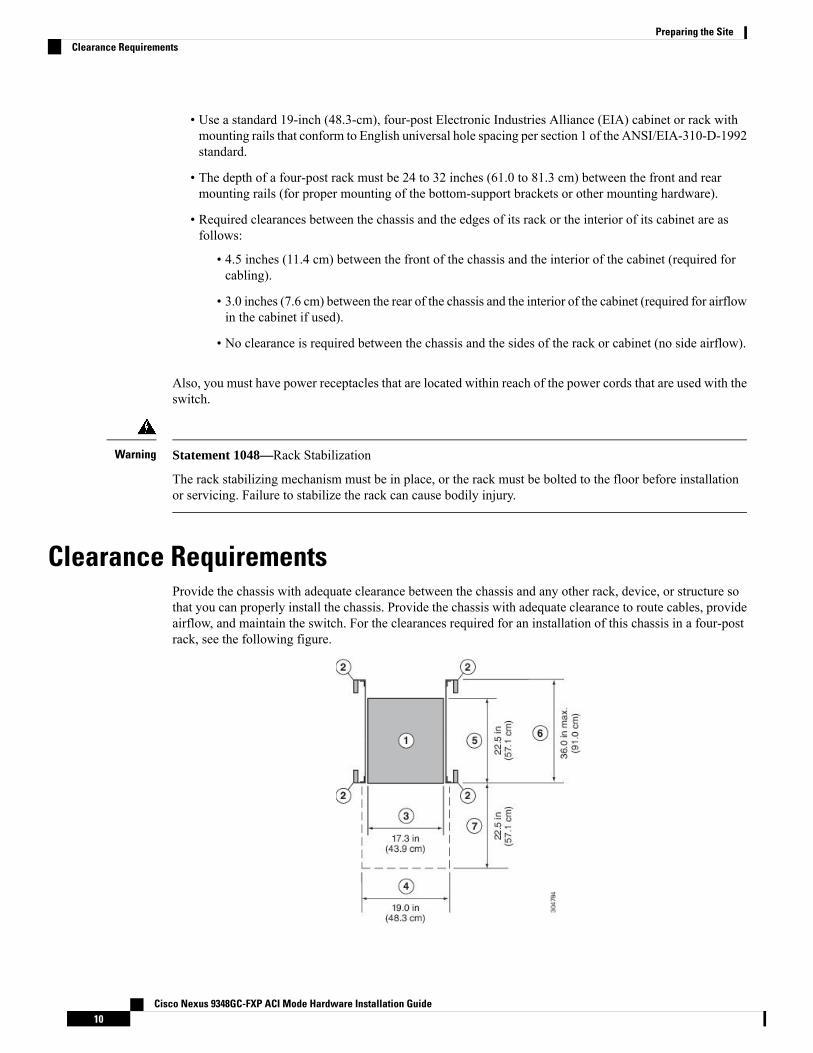
Clearance RequirementsProvide the chassis with adequate clearance between the chassis and any other rack, device, or structure sothat you can properly install the chassis. Provide the chassis with adequate clearance to route cables, provideairflow, and maintain the switch. For the clearances required for an installation of this chassis in a four-postrack, see the following figure.
Cisco Nexus 9348GC-FXP ACI Mode Hardware Installation Guide10
Preparing the SiteClearance Requirements
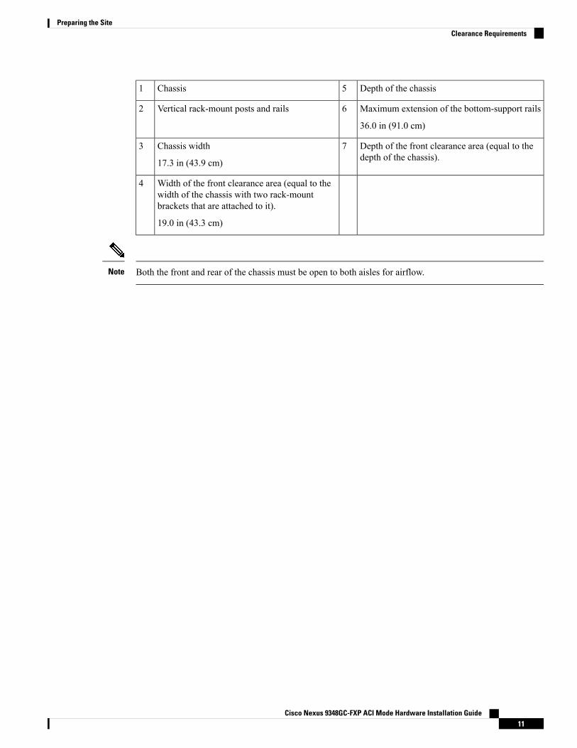
Depth of the chassis5Chassis1
Maximum extension of the bottom-support rails
36.0 in (91.0 cm)
6Vertical rack-mount posts and rails2
Depth of the front clearance area (equal to thedepth of the chassis).
7Chassis width
17.3 in (43.9 cm)
3
Width of the front clearance area (equal to thewidth of the chassis with two rack-mountbrackets that are attached to it).
19.0 in (43.3 cm)
4
Both the front and rear of the chassis must be open to both aisles for airflow.Note
Cisco Nexus 9348GC-FXP ACI Mode Hardware Installation Guide11
Preparing the SiteClearance Requirements

Cisco Nexus 9348GC-FXP ACI Mode Hardware Installation Guide12
Preparing the SiteClearance Requirements
C H A P T E R 3Installing the Switch Chassis
• Safety, on page 13• Installation Options with Rack-Mount Kits, on page 14• Airflow Considerations, on page 14• Installation Guidelines, on page 15• Unpacking and Inspecting the Switch, on page 16• Installing the Switch Using the NXK-ACC-KIT-1RU Rack-Mount Kit, on page 17• Installing the Switch Using the N3K-C3064-ACC-KIT Rack-Mount Kit, on page 20• Installing the Switch into a Two-post Rack, on page 24• Grounding the Chassis, on page 27• Starting the Switch, on page 29
SafetyBefore you install, operate, or service the switch, see the Regulatory, Compliance, and Safety Information forthe Cisco Nexus 3000 and 9000 Series for important Safety Information.
Statement 1071—Warning Definition
IMPORTANT SAFETY INSTRUCTIONS
Before you work on any equipment, be aware of the hazards involved with electrical circuitry and be familiarwith standard practices for preventing accidents. Read the installation instructions before using, installing, orconnecting the system to the power source. Use the statement number provided at the end of each warningstatement to locate its translation in the translated safety warnings for this device.
SAVE THESE INSTRUCTIONS
Warning
Cisco Nexus 9348GC-FXP ACI Mode Hardware Installation Guide13
Statement 1017—Restricted Area
This unit is intended for installation in restricted access areas. Only skilled, instructed, or qualified personnelcan access a restricted access area.
Warning
Statement 1030—Equipment Installation
Only trained and qualified personnel should be allowed to install, replace, or service this equipment.
Warning
Installation Options with Rack-Mount KitsThe rack-mount kit enables you to install the switch into racks of varying depths. You can position the switchwith easy access to either the port connections or the fan and power supply modules.
You can install the switch using the following rack-mount options:
• Rack-mount kit (NXK-ACC-KIT-1RU) which you can order from Cisco. This option offers you easyinstallation, greater stability, increased weight capacity, added accessibility, and improved removabilitywith front and rear removal.
• When installing the NXK-ACC-KIT-1RU rack-mount kit, the distance between the outside face ofthe front mounting rail and the outside face of the back mounting rail should be 25.37 to 33 inches(64.43 to 83.82 cm) to allow for rear-bracket installation.
• Rack-mount kit (N3K-C3064-ACC-KIT) which you can order from Cisco.
• When installing the N3K-C3064-ACC-KIT rack-mount kit, the distance between the outside faceof the front mounting rail and the outside face of the back mounting rail should be 22 to 30 inches(55.88 to 76.2 cm) to allow for rear-bracket installation.
The rack or cabinet that you use must meet the requirements listed the in General Requirements for Cabinetsand Racks, on page 49 section.
You are responsible for verifying that your rack and rack-mount hardware comply with the guidelines thatare described in this doc.
Note
Airflow ConsiderationsThe switch comes with fan and power supply modules that have either port-side intake or port-side exhaustairflow for cooling the switch. If you are positioning the port end of the switch in a cold aisle, make sure thatthe switch has port-side intake fan modules with burgundy coloring. If you are positioning the fan and powersupply modules in a cold aisle, make sure that the switch has port-side exhaust fan modules with blue colorings.All fan modules must have the same direction of airflow.
Cisco Nexus 9348GC-FXP ACI Mode Hardware Installation Guide14
Installing the Switch ChassisInstallation Options with Rack-Mount Kits
Installation GuidelinesWhen installing the switch, follow these guidelines:
• Ensure that there is adequate clearance space around the switch to allow for servicing the switch and foradequate airflow.
• Ensure that you are positioning the switch in a rack so that it takes in cold air from the cold aisle andexhausts air to the hot aisle. If there is blue coloring on the fan modules, the switch is configured forport-side exhaust airflow and you must position the module side of the switch in a cold aisle. If there isburgundy coloring on the fan modules, the switch is configured for port-side intake airflow and you mustposition the port side of the switch in a cold aisle.
• Ensure that the chassis can be adequately grounded. If the switch is not mounted in a grounded rack, werecommend connecting the system ground on the chassis directly to an earth ground.
• Ensure that the site power meets the power requirements for the switch. If available, you can use anuninterruptible power supply (UPS) to protect against power failures.
Avoid UPS types that use ferroresonant technology. These UPS typescan become unstable with the switch, which can have substantialcurrent draw fluctuations because of fluctuating data traffic patterns.
Caution
• Ensure that circuits are sized according to local and national codes. Typically, this often requires one orboth of the following:
• AC power supplies typically require at least a 15-A or 20-A AC circuit, 100 to 240 VAC, and afrequency of 50 to 60 Hz.
To prevent loss of input power, ensure the total maximum loads onthe circuits supplying power to the switch are within the currentratings for the wiring and breakers.
Caution
For AC input application, please refer to the statement below:Note
Statement 1005—Circuit Breaker
This product relies on the building's installation for short-circuit(overcurrent) protection. Ensure that the protective devices is ratednot greater than 20A (North America), 16A (Europe), and 13A (UK).
Warning
For DC input application, please refer to the statement below:Note
Cisco Nexus 9348GC-FXP ACI Mode Hardware Installation Guide15
Installing the Switch ChassisInstallation Guidelines

Statement 1005—Circuit Breaker
This product relies on the building's installation for short-circuit(overcurrent) protection. Ensure that the protective devices is ratednot greater than 40A for the regular DC power supplies (rated48-60VDC) and 10A for the HVDC power supplies.
Warning
Unpacking and Inspecting the SwitchBefore you install the switch, be sure to unpack and inspect the switch for damage or missing components.If anything is missing or damaged, contact your customer service representative immediately.
Keep the shipping container in case the chassis requires shipping at a later time.Tip
Before you begin
Before you unpack the switch and before you handle any switch components, be sure that you are wearing agrounded electrostatic discharge (ESD) strap. To ground the strap, attach it directly to an earth ground or toa grounded rack or grounded chassis (there must be a metal-to-metal connection to the earth ground).
Step 1 Compare the shipment to the equipment list provided by your customer service representative and verify that you havereceived all items, including the following:
• Accessory Kit
• Rack-Mount Kit
Step 2 Check for damage and report any discrepancies or damage to your customer service representative. Have the followinginformation ready:
• Invoice number of shipper (see packing slip)
• Model and serial number of the damaged unit
• Description of damage
• Effect of damage on the installation
Step 3 Check to be sure that each of the power supply and the fan tray modules have the expected direction of airflow as follows:
• Port-side intake airflow modules
• Burgundy (fan modules and AC power supplies)
• Port-side exhaust airflow modules
• Blue (fan modules and AC power supplies)
Cisco Nexus 9348GC-FXP ACI Mode Hardware Installation Guide16
Installing the Switch ChassisUnpacking and Inspecting the Switch
All power supplies and fan modules must have the same direction of airflow.Note
Installing the Switch Using the NXK-ACC-KIT-1RU Rack-MountKit
To install the switch, you must attach front and rear mounting brackets to the switch, install slider rails on therear of the rack, slide the switch onto the slider rails, and secure the switch to the front of the rack. Typically,the front of the rack is the side easiest to access for maintenance.
You must supply the eight 10-32 or 12-24 screws required to mount the slider rails and switch to the rack.Note
Before you begin
• You have inspected the switch shipment to ensure that you have everything ordered.
• Make sure that the switch rack-mount kit includes the following parts:
• Front rack-mount brackets (2)
• Rear rack-mount brackets (2)
• Slider rails (2)
• M4 x 0.7 x 8-mm Phillips countersink screws (12)
• The rack is installed and secured to its location.
Step 1 Install two front rack-mount brackets and the two rear rack-mount brackets to the switch as follows:a) Determine which end of the chassis is to be located in the cold aisle as follows:
• If the switch has port-side intake modules (fan modules with burgundy coloring), position the switch so that itsports will be in the cold aisle.
• If the switch has port-side exhaust modules (fan modules with blue coloring), position the switch so that its fanand power supply modules will be in the cold aisle.
b) Position the front rack-mount bracket and the rear rack-mount bracket so that its screw holes are aligned to the screwholes on the side of the chassis.
You can align the holes in the rack-mount bracket to the holes on the side of the chassis (see the two waysto mount these brackets on a typical chassis, in following figure). The holes that you use depend on therequirements of your rack and the amount of clearance required for interface cables (3 inches [7.6 mm]minimum) and module handles (1 inch [2.5 mm] minimum).
Note
Cisco Nexus 9348GC-FXP ACI Mode Hardware Installation Guide17
Installing the Switch ChassisInstalling the Switch Using the NXK-ACC-KIT-1RU Rack-Mount Kit
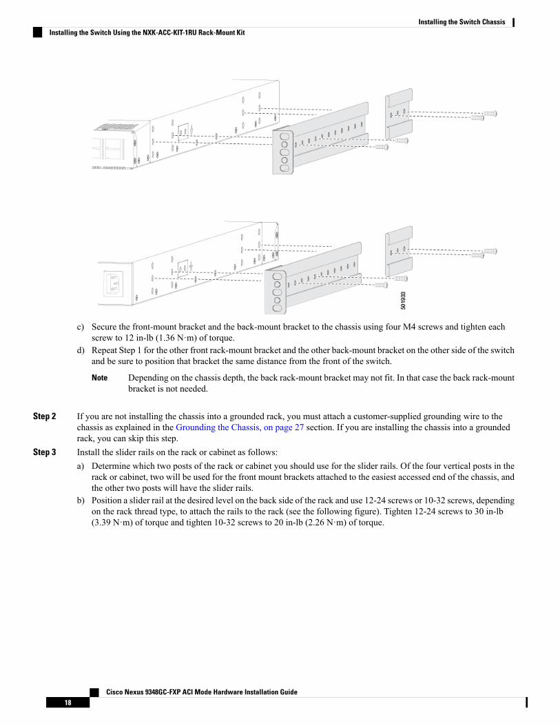
c) Secure the front-mount bracket and the back-mount bracket to the chassis using four M4 screws and tighten eachscrew to 12 in-lb (1.36 N·m) of torque.
d) Repeat Step 1 for the other front rack-mount bracket and the other back-mount bracket on the other side of the switchand be sure to position that bracket the same distance from the front of the switch.
Depending on the chassis depth, the back rack-mount bracket may not fit. In that case the back rack-mountbracket is not needed.
Note
Step 2 If you are not installing the chassis into a grounded rack, you must attach a customer-supplied grounding wire to thechassis as explained in the Grounding the Chassis, on page 27 section. If you are installing the chassis into a groundedrack, you can skip this step.
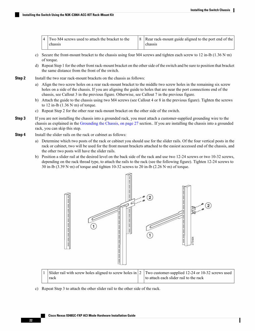
Step 3 Install the slider rails on the rack or cabinet as follows:a) Determine which two posts of the rack or cabinet you should use for the slider rails. Of the four vertical posts in the
rack or cabinet, two will be used for the front mount brackets attached to the easiest accessed end of the chassis, andthe other two posts will have the slider rails.
b) Position a slider rail at the desired level on the back side of the rack and use 12-24 screws or 10-32 screws, dependingon the rack thread type, to attach the rails to the rack (see the following figure). Tighten 12-24 screws to 30 in-lb(3.39 N·m) of torque and tighten 10-32 screws to 20 in-lb (2.26 N·m) of torque.
Cisco Nexus 9348GC-FXP ACI Mode Hardware Installation Guide18
Installing the Switch ChassisInstalling the Switch Using the NXK-ACC-KIT-1RU Rack-Mount Kit
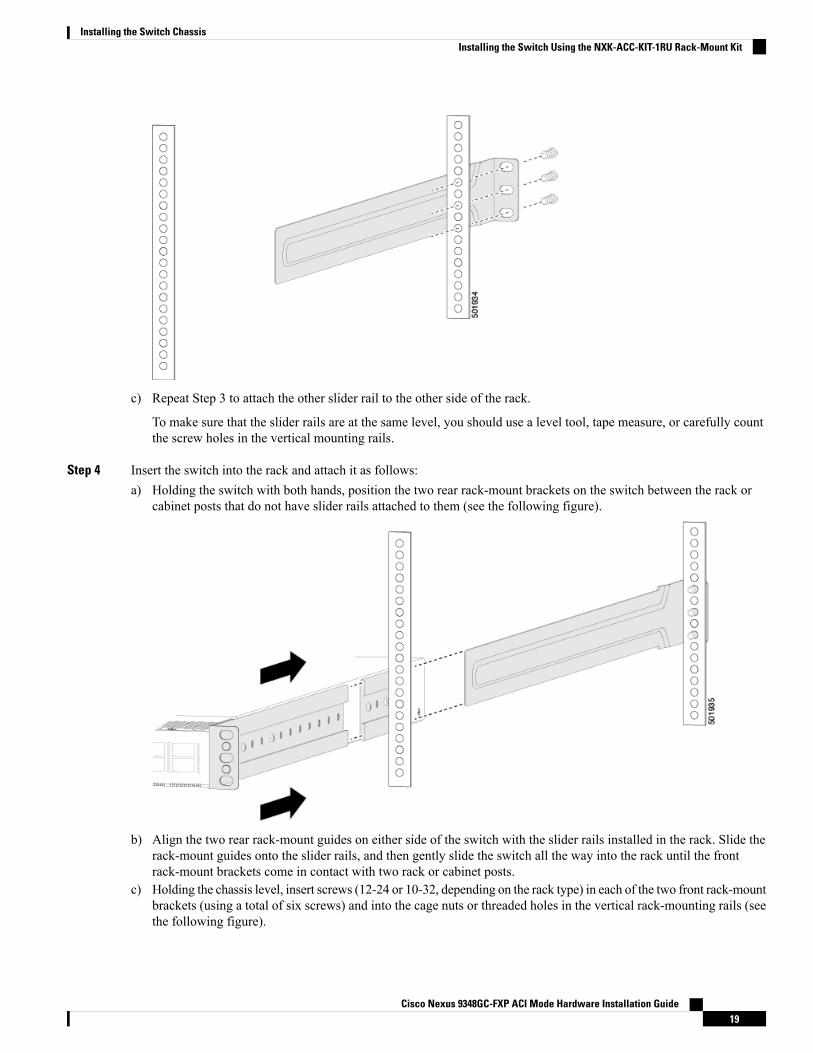
c) Repeat Step 3 to attach the other slider rail to the other side of the rack.
To make sure that the slider rails are at the same level, you should use a level tool, tape measure, or carefully countthe screw holes in the vertical mounting rails.
Step 4 Insert the switch into the rack and attach it as follows:a) Holding the switch with both hands, position the two rear rack-mount brackets on the switch between the rack or
cabinet posts that do not have slider rails attached to them (see the following figure).
b) Align the two rear rack-mount guides on either side of the switch with the slider rails installed in the rack. Slide therack-mount guides onto the slider rails, and then gently slide the switch all the way into the rack until the frontrack-mount brackets come in contact with two rack or cabinet posts.
c) Holding the chassis level, insert screws (12-24 or 10-32, depending on the rack type) in each of the two front rack-mountbrackets (using a total of six screws) and into the cage nuts or threaded holes in the vertical rack-mounting rails (seethe following figure).
Cisco Nexus 9348GC-FXP ACI Mode Hardware Installation Guide19
Installing the Switch ChassisInstalling the Switch Using the NXK-ACC-KIT-1RU Rack-Mount Kit
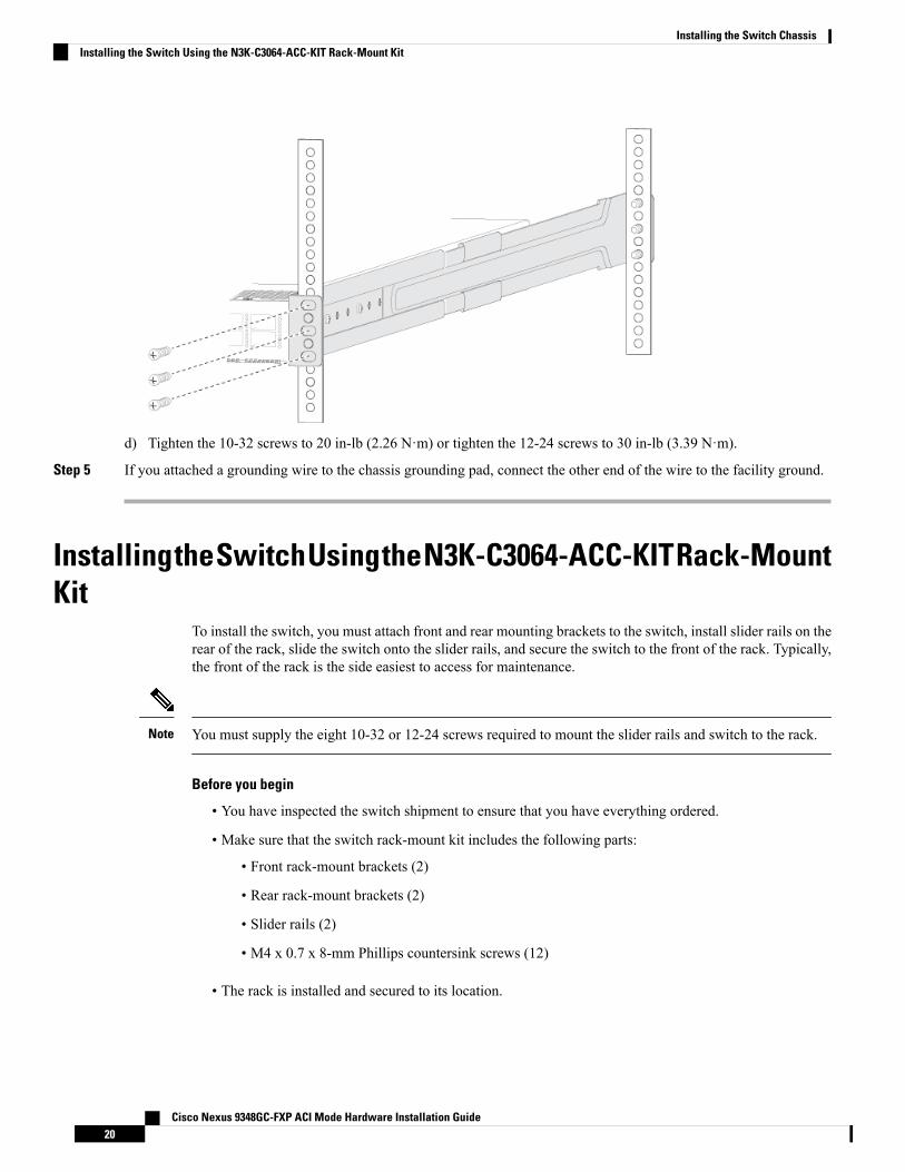
d) Tighten the 10-32 screws to 20 in-lb (2.26 N·m) or tighten the 12-24 screws to 30 in-lb (3.39 N·m).
Step 5 If you attached a grounding wire to the chassis grounding pad, connect the other end of the wire to the facility ground.
InstallingtheSwitchUsingtheN3K-C3064-ACC-KITRack-MountKit
To install the switch, you must attach front and rear mounting brackets to the switch, install slider rails on therear of the rack, slide the switch onto the slider rails, and secure the switch to the front of the rack. Typically,the front of the rack is the side easiest to access for maintenance.
You must supply the eight 10-32 or 12-24 screws required to mount the slider rails and switch to the rack.Note
Before you begin
• You have inspected the switch shipment to ensure that you have everything ordered.
• Make sure that the switch rack-mount kit includes the following parts:
• Front rack-mount brackets (2)
• Rear rack-mount brackets (2)
• Slider rails (2)
• M4 x 0.7 x 8-mm Phillips countersink screws (12)
• The rack is installed and secured to its location.
Cisco Nexus 9348GC-FXP ACI Mode Hardware Installation Guide20
Installing the Switch ChassisInstalling the Switch Using the N3K-C3064-ACC-KIT Rack-Mount Kit
Step 1 Install two front-mount brackets to the switch as follows:a) Determine which end of the chassis is to be located in the cold aisle as follows:
• If the switch has port-side intake modules (fan modules with burgundy coloring), position the switch so that itsports will be in the cold aisle.
• If the switch has port-side exhaust modules (fan modules with blue coloring), position the switch so that its fanand power supply modules will be in the cold aisle.
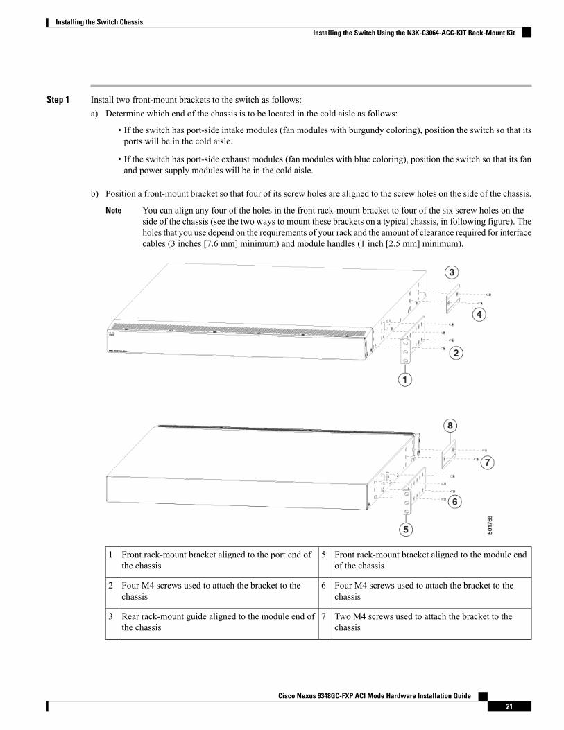
b) Position a front-mount bracket so that four of its screw holes are aligned to the screw holes on the side of the chassis.
You can align any four of the holes in the front rack-mount bracket to four of the six screw holes on theside of the chassis (see the two ways to mount these brackets on a typical chassis, in following figure). Theholes that you use depend on the requirements of your rack and the amount of clearance required for interfacecables (3 inches [7.6 mm] minimum) and module handles (1 inch [2.5 mm] minimum).
Note
Front rack-mount bracket aligned to the module endof the chassis
5Front rack-mount bracket aligned to the port end ofthe chassis
1
Four M4 screws used to attach the bracket to thechassis
6Four M4 screws used to attach the bracket to thechassis
2
Two M4 screws used to attach the bracket to thechassis
7Rear rack-mount guide aligned to the module end ofthe chassis
3
Cisco Nexus 9348GC-FXP ACI Mode Hardware Installation Guide21
Installing the Switch ChassisInstalling the Switch Using the N3K-C3064-ACC-KIT Rack-Mount Kit
Rear rack-mount guide aligned to the port end of thechassis
8Two M4 screws used to attach the bracket to thechassis
4
c) Secure the front-mount bracket to the chassis using four M4 screws and tighten each screw to 12 in-lb (1.36 N·m)of torque.
d) Repeat Step 1 for the other front rack-mount bracket on the other side of the switch and be sure to position that bracketthe same distance from the front of the switch.
Step 2 Install the two rear rack-mount brackets on the chassis as follows:a) Align the two screw holes on a rear rack-mount bracket to the middle two screw holes in the remaining six screw
holes on a side of the chassis. If you are aligning the guide to holes that are near the port connections end of thechassis, see Callout 3 in the previous figure. Otherwise, see Callout 7 in the previous figure.
b) Attach the guide to the chassis using two M4 screws (see Callout 4 or 8 in the previous figure). Tighten the screwsto 12 in-lb (1.36 N·m) of torque.
c) Repeat Step 2 for the other rear rack-mount bracket on the other side of the switch.
Step 3 If you are not installing the chassis into a grounded rack, you must attach a customer-supplied grounding wire to thechassis as explained in the Grounding the Chassis, on page 27 section.. If you are installing the chassis into a groundedrack, you can skip this step.
Step 4 Install the slider rails on the rack or cabinet as follows:a) Determine which two posts of the rack or cabinet you should use for the slider rails. Of the four vertical posts in the
rack or cabinet, two will be used for the front mount brackets attached to the easiest accessed end of the chassis, andthe other two posts will have the slider rails.
b) Position a slider rail at the desired level on the back side of the rack and use two 12-24 screws or two 10-32 screws,depending on the rack thread type, to attach the rails to the rack (see the following figure). Tighten 12-24 screws to30 in-lb (3.39 N·m) of torque and tighten 10-32 screws to 20 in-lb (2.26 N·m) of torque.
Two customer-supplied 12-24 or 10-32 screws usedto attach each slider rail to the rack
2Slider rail with screw holes aligned to screw holes inrack
1
c) Repeat Step 3 to attach the other slider rail to the other side of the rack.
Cisco Nexus 9348GC-FXP ACI Mode Hardware Installation Guide22
Installing the Switch ChassisInstalling the Switch Using the N3K-C3064-ACC-KIT Rack-Mount Kit

To make sure that the slider rails are at the same level, you should use a level tool, tape measure, or carefully countthe screw holes in the vertical mounting rails.
Step 5 Insert the switch into the rack and attach it as follows:a) Holding the switch with both hands, position the two rear rack-mount brackets on the switch between the rack or
cabinet posts that do not have slider rails attached to them (see the following figure).
Front-mount brackets.3Align the two rear rack-mount bracket guides withthe slider rails installed in the rack.
1
Mounting rails on rack or cabinet posts.4Slide the rack-mount guides onto the slider rails untilthe front rack-mount brackets come in contact withthe front rack-mount rails.
2
b) Align the two rear rack-mount guides on either side of the switch with the slider rails installed in the rack. Slide therack-mount guides onto the slider rails, and then gently slide the switch all the way into the rack until the frontrack-mount brackets come in contact with two rack or cabinet posts.
c) Holding the chassis level, insert two screws (12-24 or 10-32, depending on the rack type) in each of the two frontrack-mount brackets (using a total of four screws) and into the cage nuts or threaded holes in the vertical rack-mountingrails (see the following figure).
Cisco Nexus 9348GC-FXP ACI Mode Hardware Installation Guide23
Installing the Switch ChassisInstalling the Switch Using the N3K-C3064-ACC-KIT Rack-Mount Kit
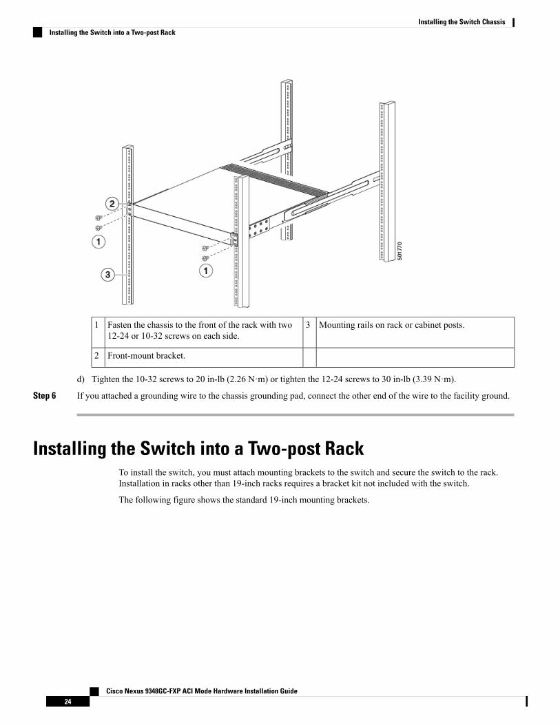
Mounting rails on rack or cabinet posts.3Fasten the chassis to the front of the rack with two12-24 or 10-32 screws on each side.
1
Front-mount bracket.2
d) Tighten the 10-32 screws to 20 in-lb (2.26 N·m) or tighten the 12-24 screws to 30 in-lb (3.39 N·m).
Step 6 If you attached a grounding wire to the chassis grounding pad, connect the other end of the wire to the facility ground.
Installing the Switch into a Two-post RackTo install the switch, you must attach mounting brackets to the switch and secure the switch to the rack.Installation in racks other than 19-inch racks requires a bracket kit not included with the switch.
The following figure shows the standard 19-inch mounting brackets.
Cisco Nexus 9348GC-FXP ACI Mode Hardware Installation Guide24
Installing the Switch ChassisInstalling the Switch into a Two-post Rack
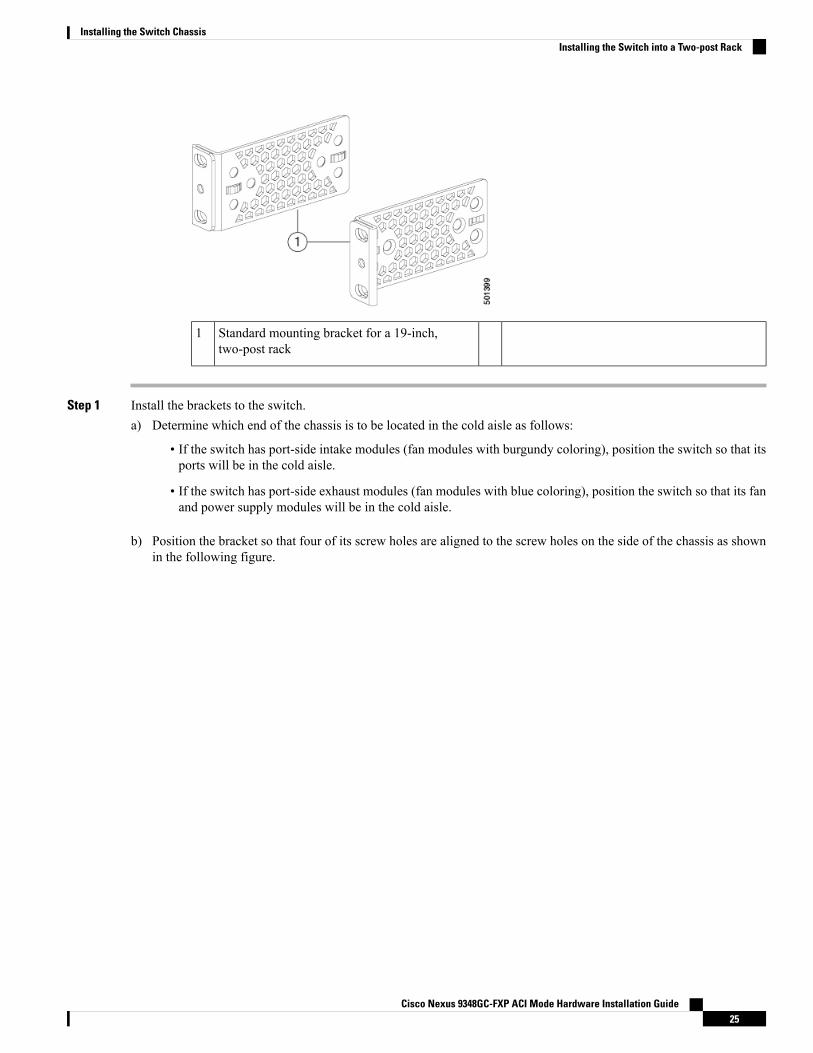
Standard mounting bracket for a 19-inch,two-post rack
1
Step 1 Install the brackets to the switch.a) Determine which end of the chassis is to be located in the cold aisle as follows:
• If the switch has port-side intake modules (fan modules with burgundy coloring), position the switch so that itsports will be in the cold aisle.
• If the switch has port-side exhaust modules (fan modules with blue coloring), position the switch so that its fanand power supply modules will be in the cold aisle.
b) Position the bracket so that four of its screw holes are aligned to the screw holes on the side of the chassis as shownin the following figure.
Cisco Nexus 9348GC-FXP ACI Mode Hardware Installation Guide25
Installing the Switch ChassisInstalling the Switch into a Two-post Rack
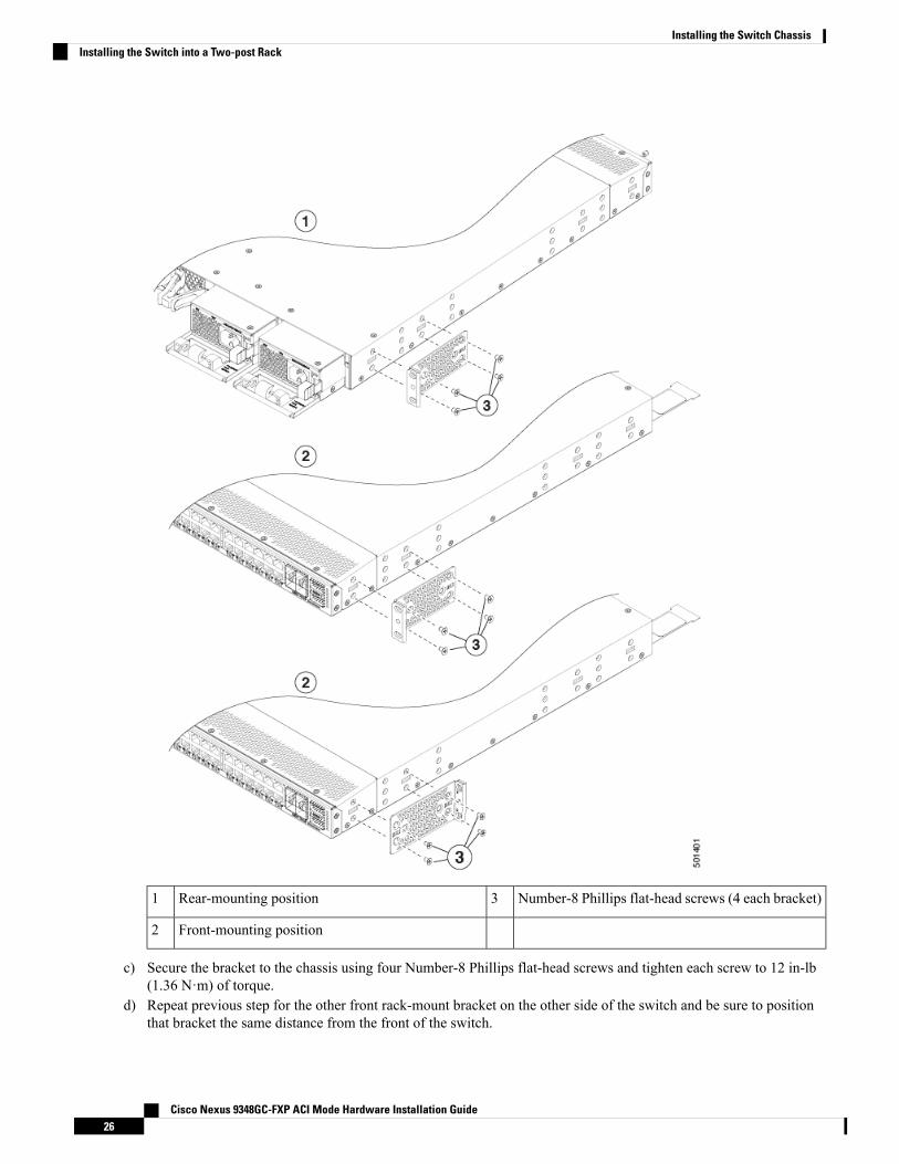
Number-8 Phillips flat-head screws (4 each bracket)3Rear-mounting position1
Front-mounting position2
c) Secure the bracket to the chassis using four Number-8 Phillips flat-head screws and tighten each screw to 12 in-lb(1.36 N·m) of torque.
d) Repeat previous step for the other front rack-mount bracket on the other side of the switch and be sure to positionthat bracket the same distance from the front of the switch.
Cisco Nexus 9348GC-FXP ACI Mode Hardware Installation Guide26
Installing the Switch ChassisInstalling the Switch into a Two-post Rack
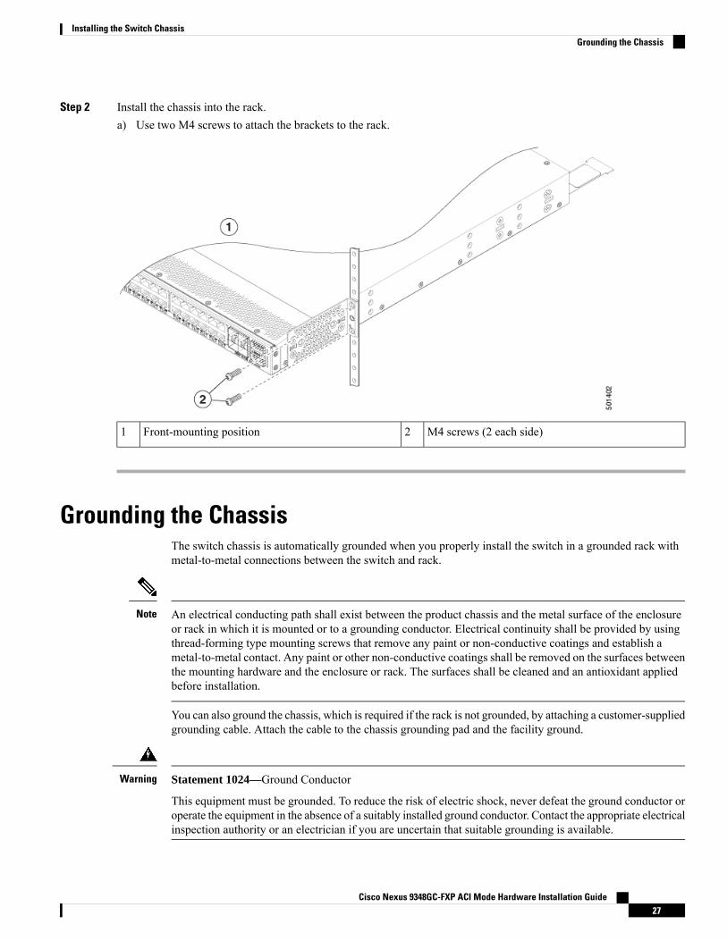
Step 2 Install the chassis into the rack.a) Use two M4 screws to attach the brackets to the rack.
M4 screws (2 each side)2Front-mounting position1
Grounding the ChassisThe switch chassis is automatically grounded when you properly install the switch in a grounded rack withmetal-to-metal connections between the switch and rack.
An electrical conducting path shall exist between the product chassis and the metal surface of the enclosureor rack in which it is mounted or to a grounding conductor. Electrical continuity shall be provided by usingthread-forming type mounting screws that remove any paint or non-conductive coatings and establish ametal-to-metal contact. Any paint or other non-conductive coatings shall be removed on the surfaces betweenthe mounting hardware and the enclosure or rack. The surfaces shall be cleaned and an antioxidant appliedbefore installation.
Note
You can also ground the chassis, which is required if the rack is not grounded, by attaching a customer-suppliedgrounding cable. Attach the cable to the chassis grounding pad and the facility ground.
Statement 1024—Ground Conductor
This equipment must be grounded. To reduce the risk of electric shock, never defeat the ground conductor oroperate the equipment in the absence of a suitably installed ground conductor. Contact the appropriate electricalinspection authority or an electrician if you are uncertain that suitable grounding is available.
Warning
Cisco Nexus 9348GC-FXP ACI Mode Hardware Installation Guide27
Installing the Switch ChassisGrounding the Chassis

Statement 1046—Installing or Replacing the Unit
To reduce risk of electric shock, when installing or replacing the unit, the ground connection must always bemade first and disconnected last.
Warning
Before you begin
Before you can ground the chassis, you must have a connection to the earth ground for the data center building.
Step 1 Use a wire-stripping tool to remove approximately 0.75 inch (19 mm) of the covering from the end of the groundingwire. We recommend 6-AWG wire for the U.S. installations.
Step 2 Insert the stripped end of the grounding wire into the open end of the grounding lug. Use a crimping tool to crimp thelug to the wire, see the following figure. Verify that the ground wire is securely attached to the grounding lug by attemptingto pull the wire out of the crimped lug.
2 M4 screws are used tosecure the grounding lug tothe chassis
3Chassis grounding pad1
Grounding cable, with 0.75in. (19 mm) of insulation thatis stripped from one end,which is inserted into thegrounding lug and crimpedin place
2
Step 3 Secure the grounding lug to the chassis grounding pad with two M4 screws, see the previous figure. Tighten the screwsto 11 to 15 in-lb (1.24 to 1.69 N·m) of torque.
Step 4 Prepare the other end of the grounding wire and connect it to the facility ground.
Cisco Nexus 9348GC-FXP ACI Mode Hardware Installation Guide28
Installing the Switch ChassisGrounding the Chassis
Starting the SwitchYou start the switch by connecting it to its dedicated power source. If you need n+1 redundancy, you mustconnect each of the power supplies to one or two power sources. If you need n+n redundancy, you mustconnect each power supply in a switch to a different power source.
This equipment is designed to boot up in less than 30 minutes, dependent on its neighboring devices beingfully up and running.
Note
Before you begin
• The switch must be installed and secured to a rack or cabinet.
• The switch must be adequately grounded.
• The rack must be close enough to the dedicated power source so that you can connect the switch to thepower source by using a designated power cables.
• You have the designated power cables for the power supplies that you are connecting to the dedicatedpower sources.
Depending on the outlet receptacle on your AC power distributionunit, you might need an optional jumper power cord to connect theswitch to your outlet receptacle.
Note
• The switch is not connected to the network (this includes any management or interface connections).
• The fan and power supply modules are fully secured in their chassis slots.
Step 1 For each AC power supply, do the following:a) Using the recommended AC power cable for your country or region, connect one end to the AC power supply.b) Connect the other end of the power cable to the AC power source.
Step 2 For each HVAC/HVDC power supply, connect it to a power source as follows:a) Using the recommended high voltage power cable for your country or region, connect the Anderson Power Saf-D-Grid
connector on the power cable to the power receptacle on the power supply. Make sure that the connector clicks whenfully pushed into the receptacle.
b) Connect the other end of the power cable to a power source.
• When connecting to an HVAC power source, insert the C14 or LS-25 plug in a receptacle for the HVAC powersource.
• When connecting to an HVDC power source, do the following:
1. Verify that the power is turned off at a circuit breaker for the power source terminals.
2. Remove the nuts from each of the terminal posts for the power supply.
Cisco Nexus 9348GC-FXP ACI Mode Hardware Installation Guide29
Installing the Switch ChassisStarting the Switch
3. Place the power cable negative-wire terminal ring on the negative terminal for the power source and securethem with a terminal nut.
4. Place the power cable positive-wire terminal ring on the positive terminal for the power source and securethem with a terminal nut.
5. Place the power cable ground-wire terminal ring on the ground terminal for the power source and securethem with a terminal nut.
6. If there is a safety cover for the power source terminals, place and secure it over the terminals to avoid anelectrical shock hazard.
7. Turn on the power at the power source circuit breaker.
Step 3 For each DC power supply, do the following:a) Turn off the circuit breaker for the power source to avoid an electrical shock hazard.b) Verify that the power cable wires from the power source are connected to a connector block.c) Insert the connector block into the receptacle on the power supply. Make sure that the connector block clicks when
fully inserted in the receptacle and does not pull out.d) If there is a safety cover for the terminals, place and secure it over the terminals to avoid an electrical shock hazard.e) Turn on the power at the circuit breaker for the DC power source.
Step 4 Verify that the power supply LED is on and green.Step 5 Listen for the fans; they should begin operating when the power supply is powered.Step 6 After the switch boots, verify that the following LEDs are lit:
• On the fan modules, the Status (STA or STS) LED is green.
If a fan module Status LED is not green, try reinstalling the fan module.
• After initialization, the switch chassis Status (labeled as STA or STS) LED is green.
Step 7 Verify that the system software has booted and the switch has initialized without error messages.
A setup utility automatically launches the first time that you access the switch and guides you through the basicconfiguration. For instructions on how to configure the switch and check module connectivity, see the appropriate CiscoNexus 9000 Series configuration guide.
Cisco Nexus 9348GC-FXP ACI Mode Hardware Installation Guide30
Installing the Switch ChassisStarting the Switch
C H A P T E R 4Connecting the Switch to the ACI Fabric
• ACI Fabric Topology, on page 31• Preparing to Connect to Other Devices, on page 32• Connecting Leaf Switches to APICs, on page 33• Connecting Leaf Switches to Spine Switches, on page 35• Installing a Gigabit Ethernet module (GEM), on page 36• Virtual Port Channel Migration - Migration of Nodes from a First-Generation Switch to aSecond-Generation Switch, on page 36
• Setting Up an Optional Console Interface, on page 37• Setting Up an Optional Management Connection, on page 38• Optic Transceiver Removal Using the Optics Extraction Tool , on page 39• Maintaining Transceivers and Optical Cables, on page 40
ACI Fabric TopologyThe ACI fabric topology includes the following major components:
• Application Centric Infrastructure Controller (APIC) appliance (cluster of APICs)
• Leaf switches (for switch compatibility, please see the data sheets).
• Spine switches (for switch compatibility, please see the data sheets).
For additional information, please see the Cisco APIC Installation, Upgrade, and Downgrade Guide.
To prevent sub-optimal forwarding between endpoints, connect every leaf switch in the fabric to every spineswitch in the same fabric.
Note
As shown in the following figure, each APIC is connected to one or two leaf switches and each leaf switchshould be connected to every spine switch in the same fabric.
Cisco Nexus 9348GC-FXP ACI Mode Hardware Installation Guide31
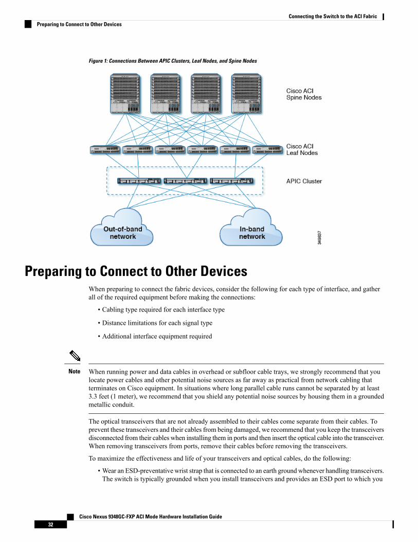
Figure 1: Connections Between APIC Clusters, Leaf Nodes, and Spine Nodes
Preparing to Connect to Other DevicesWhen preparing to connect the fabric devices, consider the following for each type of interface, and gatherall of the required equipment before making the connections:
• Cabling type required for each interface type
• Distance limitations for each signal type
• Additional interface equipment required
When running power and data cables in overhead or subfloor cable trays, we strongly recommend that youlocate power cables and other potential noise sources as far away as practical from network cabling thatterminates on Cisco equipment. In situations where long parallel cable runs cannot be separated by at least3.3 feet (1 meter), we recommend that you shield any potential noise sources by housing them in a groundedmetallic conduit.
Note
The optical transceivers that are not already assembled to their cables come separate from their cables. Toprevent these transceivers and their cables from being damaged, we recommend that you keep the transceiversdisconnected from their cables when installing them in ports and then insert the optical cable into the transceiver.When removing transceivers from ports, remove their cables before removing the transceivers.
To maximize the effectiveness and life of your transceivers and optical cables, do the following:
• Wear an ESD-preventative wrist strap that is connected to an earth ground whenever handling transceivers.The switch is typically grounded when you install transceivers and provides an ESD port to which you
Cisco Nexus 9348GC-FXP ACI Mode Hardware Installation Guide32
Connecting the Switch to the ACI FabricPreparing to Connect to Other Devices
can connect your wrist strap. If you cannot find an ESD port, connect the wrist strap to an earth ground(such as the grounding connection for the chassis).
• Do not remove or insert a transceiver more often than necessary. Repeated removals and insertions canshorten its useful life.
• Keep the transceivers and fiber-optic cables clean and dust free to maintain high signal accuracy and toprevent damage to the connectors. Attenuation (loss of light) increases with contamination and shouldbe kept below 0.35 dB.
• Clean these parts before installing them to prevent dust from scratching the fiber-optic cable ends.
• Clean the connectors regularly; the required frequency of cleaning depends upon the environment.In addition, clean connectors if they are exposed to dust or accidentally touched. Both wet and drycleaning techniques can be effective; refer to your site's fiber-optic connection cleaning procedures.
• Do not touch the ends of connectors. Touching the ends can leave fingerprints and cause othercontamination.
• Inspect routinely for dust and damage. If you suspect damage, clean and then inspect fiber ends under amicroscope to determine if damage has occurred.
Connecting Leaf Switches to APICsYou must downlink one or two (recommended for redundancy) Cisco Nexus 9300 platform ACI-mode leafswitches to each Application Policy Infrastructure Controller (APIC) in your ACI fabric. The type of virtualinterface card (VIC) installed on the APIC determines the types of interface cables that you can use to connectthe leaf switches to the APICs.
• The VIC 1225T module supports copper connectors, copper cables, and switches with copper downlinkports (such as: Cisco Nexus 93108TC-FX switche).
• The VIC 1225 module supports optical transceivers, optical cables, and switches with optical downlinkports (such as: Cisco Nexus 93600CD-GX switche).
• The VIC 1455 module supports optical transceivers, optical cables, and switches with optical downlinkports (such as: Cisco Nexus 93600CD-GX switche).
Breakout ports cannot be used for Cisco APIC connectivity.Note
Before you begin
The APIC and leaf switches in the fabric must be fully installed in their racks and grounded.
Step 1 Connect an interface cable to one of the two to four ports on the virtual interface card (VIC) installed on the APIC. If thecable is not already assembled to its transceivers, insert the transceiver into the VIC port and then connect the opticalinterface cable to the transceiver.
• For a VIC 1225T 10GBASE-T copper module, use 10GBASE-T cables with RJ-45 connectors.
Cisco Nexus 9348GC-FXP ACI Mode Hardware Installation Guide33
Connecting the Switch to the ACI FabricConnecting Leaf Switches to APICs

• For a VIC 1225 optical module, use one of the following sets of transceivers and cables:
• Cisco 10GBASE-LR transceivers (SFP-10G-LR) supporting a link length of up to 6.1 miles (10 km)
• Cisco 10GBASE-SR transceivers (SFP-10G-SR) supporting the following link lengths:
• Using 2000 MHz MMF (OM3) for up to 984 feet (300 m)
• Using 4700 MHz MMF (OM4) for up to 1312 feet (400 m)
• Cisco SFP+ Active Optical Cables (SFP-10G-AOCxM [where x=1, 3, 5, 7 for lengths in meters])
• Cisco SFP+ Twinax Cables (SFP-H10GB-CUxM [where x=7 for lengths in meters])
• For a VIC 1455 SFP28 module, 10-Gigabit only, use one of the following sets of transceivers and cables:
• Cisco 10GBASE-LR transceivers (SFP-10G-LR) supporting a link length of up to 6.1 miles (10 km)
• Cisco 10GBASE-SR transceivers (SFP-10G-SR) supporting the following link lengths:
• Using 2000 MHz MMF (OM3) for up to 984 feet (300 m)
• Using 4700 MHz MMF (OM4) for up to 1312 feet (400 m)
• Cisco SFP+ Active Optical Cables (SFP-10G-AOCxM [where x=1, 2, 3, 5, 7, or 10 for lengths in meters])
• Cisco SFP+ Twinax Cables (SFP-H10GB-CUxM [where x=1, 2, 3, 5, 7, or 10 for lengths in meters])
The VIC 1455 has 4 ports, port-1, port-2, port-3, and port-4 from left to right.Note
• All ports must have the same speed, either 10-Gigabit or 25-Gigabit.
• Port-1 and port-2 is one pair, corresponding to eth2-1 on APIC and port-3 and port-4 is another pair,corresponding to eth2-2 on APIC. Only one connection is allowed for each pair. For example, you can connectone cable to either port-1 or port-2, and connect another cable to either port-3 or port-4 (please do not connecttwo cables on any pair).
To determine which transceivers, adapters, and cables support this switch, see the Cisco Transceiver ModulesCompatibility Information document.
To see the transceiver specifications and installation information, see Transceiver Module Installation Guides.
Step 2 Connect the other end of the interface cable to a downlink port on a leaf switch.
• For a Cisco 10GBASE-LR or -SR transceiver and cable, insert the transceiver into a downlink optical port on a leafswitch before connecting the cable to the transceiver.
• For Cisco SFP+ Active Optical Cables, insert the transceiver on the cable into a downlink optical port on a leafswitch.
• For a 10GBASE-T copper cable, insert the RJ-45 connector on the cable into a downlink BASE-T port on a leafswitch.
To determine which transceivers, adapters, and cables support this switch, see the Cisco Transceiver ModulesCompatibility Information document.
Note
Cisco Nexus 9348GC-FXP ACI Mode Hardware Installation Guide34
Connecting the Switch to the ACI FabricConnecting Leaf Switches to APICs
Connecting Leaf Switches to Spine SwitchesFor optimal forwarding between endpoints, you must connect each leaf switch to every spine switch in thesame ACI fabric.
To determine which transceivers, adapters, and cables support this switch, see the Cisco Transceiver ModulesCompatibility Information document.
To see the transceiver specifications and installation information, see TransceiverModule Installation Guides.
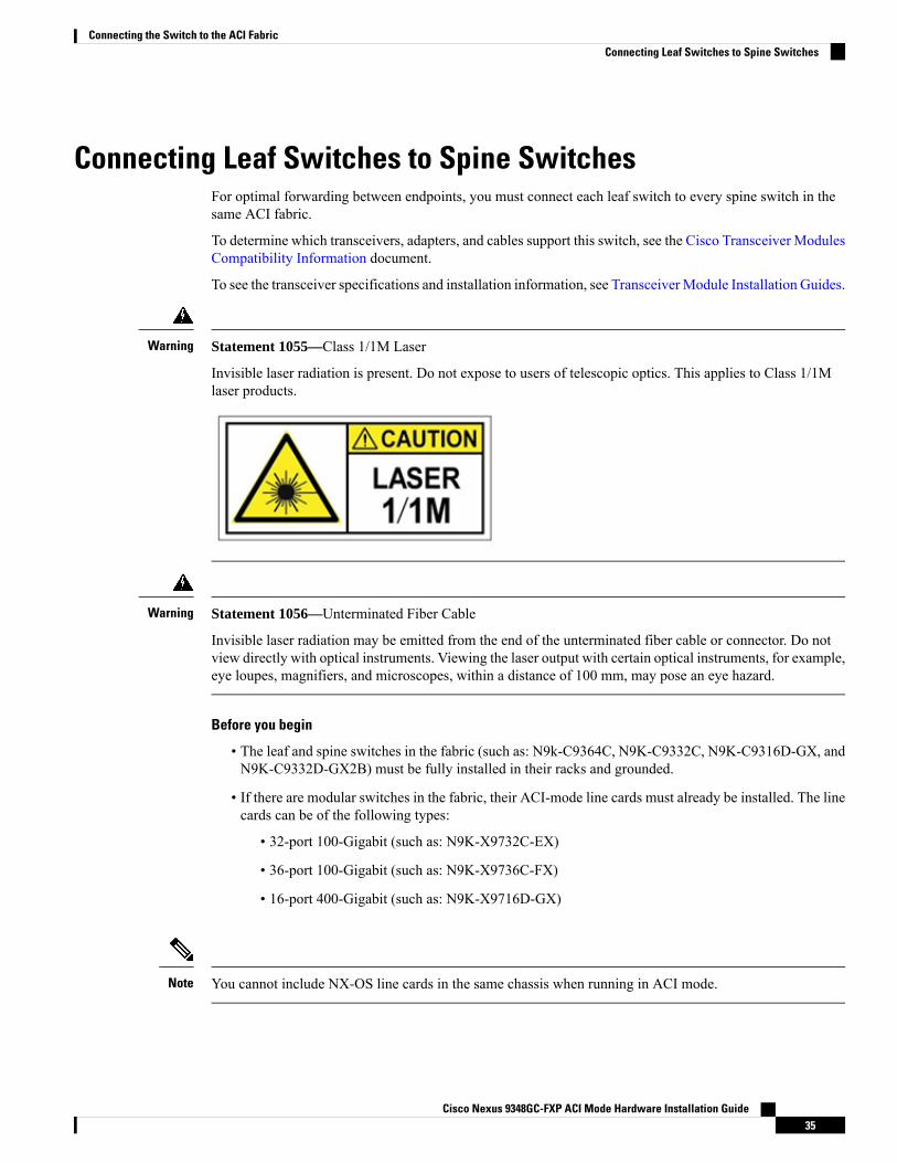
Statement 1055—Class 1/1M Laser
Invisible laser radiation is present. Do not expose to users of telescopic optics. This applies to Class 1/1Mlaser products.
Warning
Statement 1056—Unterminated Fiber Cable
Invisible laser radiation may be emitted from the end of the unterminated fiber cable or connector. Do notview directly with optical instruments. Viewing the laser output with certain optical instruments, for example,eye loupes, magnifiers, and microscopes, within a distance of 100 mm, may pose an eye hazard.
Warning
Before you begin
• The leaf and spine switches in the fabric (such as: N9k-C9364C, N9K-C9332C, N9K-C9316D-GX, andN9K-C9332D-GX2B) must be fully installed in their racks and grounded.
• If there are modular switches in the fabric, their ACI-mode line cards must already be installed. The linecards can be of the following types:
• 32-port 100-Gigabit (such as: N9K-X9732C-EX)
• 36-port 100-Gigabit (such as: N9K-X9736C-FX)
• 16-port 400-Gigabit (such as: N9K-X9716D-GX)
You cannot include NX-OS line cards in the same chassis when running in ACI mode.Note
Cisco Nexus 9348GC-FXP ACI Mode Hardware Installation Guide35
Connecting the Switch to the ACI FabricConnecting Leaf Switches to Spine Switches
Multiple uplinks from a leaf switch to a spine switch is supported. A symmetrical topology is recommendedso that all devices have equal access to resources.
Note
Step 1 For the transceivers with removable cables, make sure that the transceivers are separated from their interface cables.Step 2 Insert the appropriate transceiver into an active uplink port on the leaf switch.Step 3 Insert the same type of transceiver in the spine switch port on the line card.Step 4 For transceivers with removable cables, insert the interface cable into the open end of each of those transceivers.Step 5 Repeat Steps 1 through 4 for each spine switch in the ACI fabric.
The leaf switch is connected to each spine switch in the ACI fabric.Step 6 Repeat Steps 1 through 5 for each leaf switch in the ACI fabric.
Each leaf switch in the ACI fabric is connected to each spine switch in the network,
The fabric automatically implements Equal Cost Multi-Pathing (ECMP) and enables all links. You do notneed to configure the links.
Installing a Gigabit Ethernet module (GEM)
Step 1 Clear the switch's current configuration by using the setup-clean-config command.Step 2 Power off the switch by disconnecting the power.Step 3 Replace the current GEM card with the new GEM card.Step 4 Power on the switch.
Virtual Port Channel Migration - Migration of Nodes from aFirst-Generation Switch to a Second-Generation Switch
Initially the fabric is configured with vPCs between two first-generation switches. Traffic flows are designedso that only these vPCs are used for data traffic. Now that you want to migrate both of the first-generationswitches to second-generation switches, the following steps are required.
For this procedure, vPC primary and vPC secondary are first generation switches in vPC pair, sending trafficas described above.
To determine which transceivers, adapters, and cables support this switch, see the Cisco Transceiver ModulesCompatibility Information document.
To see the transceiver specifications and installation information, see TransceiverModule Installation Guides.
Cisco Nexus 9348GC-FXP ACI Mode Hardware Installation Guide36
Connecting the Switch to the ACI FabricInstalling a Gigabit Ethernet module (GEM)

Before you begin
You have two first-generation Cisco Nexus 9000 Series switches comprising a virtual port channel (vPC).You are migrating to two second-generation Cisco Nexus 9000 Series switches using the same cables.
First-generation Cisco Nexus 9000 Series switches include those switches that do not contain an EX or anFX in the PID (product identification).
Second-generation Cisco Nexus 9000 Series switches include those switches that have an EX or an FX in thePID.
Move any APIC controllers that are connected to the migrating vPC first-generation switches to any otherswitches in the fabric and wait for the APIC cluster to become "Fully Fit".
Step 1 From the APICGUI, perform theRemove From Controller operation for vPC secondary. The switch is clean rebootedby the APIC. Wait for about 10 minutes for this operation to finish. This action prompts all traffic to use the otherfirst-generation switch for data traffic. Disconnect the cabling from vPC secondary.
Step 2 Uninstall the first-generation switch by reversing the order of the steps in the Installing the Switch Chassis section, ofthe switch specific Hardware Installation Guide.
Step 3 Install the second-generation switch by following the steps in the Installing the Switch Chassis section, of the switchspecific Hardware Installation Guide.
Step 4 Connect the loose cabling that you removed from the first-generation switch, to the same ports on the second-generationswitch.
Step 5 Now you register the new second-generation switch with the APIC. Register the new node with the same node nameand node ID. This switch becomes part of the fabric. Policies are pushed to the new switch and the vPC legs are keptdown since there is a mismatch of generation switches. At this point, vPC primary continues to send the data traffic.
Step 6 From the APIC GUI, perform the Remove From Controller operation for vPC primary. This switch is clean rebootedby the APIC.
Wait for about 10 minutes for this operation to finish. The vPC leg on the second-generation switch, which was keptdown earlier comes up. This action prompts all traffic to move to the new second-generation switch. Please note thevPC ports on the new second-generation switch will come up in about 10 to 22 seconds when STP is disabled for thedeployed VLANs on the remote devices, and there will be traffic drops in the range of 10 to 40 seconds, dependingupon the flows in the fabric. When STP is enabled on the VLANs on the remote devices, the traffic loss will be in therange of 40 to 75 seconds, depending upon the flows in the fabric.
Step 7 Disconnect the cabling from the other first-generation switch.Step 8 Uninstall the first-generation switch, like you did in step 2.Step 9 Install the second-generation switch, like you did in step 3.Step 10 Connect the loose cabling, like you did in step 4.Step 11 Register the new second-generation switch with the APIC. Register the new node with the same node name and node
ID. This switch becomes part of the fabric. Policies are pushed to the new switch and the vPC legs comes up and startspassing traffic.
Setting Up an Optional Console InterfaceYou can optionally set up a console interface for performing the initial configuration of the switch. To dothis, use the interface cable provided in the accessory kit to connect the switch to your console device. You
Cisco Nexus 9348GC-FXP ACI Mode Hardware Installation Guide37
Connecting the Switch to the ACI FabricSetting Up an Optional Console Interface
can connect the console port on the switch to a modem. If you do not connect it to a modem, make theconnection either before powering up the switch or after completing the boot process for the switch.
Before you begin
The console device must support VT100 terminal emulations and asynchronous transmissions.
Step 1 Configure the terminal emulator program to match each of the following default port characteristics:
• 9600 baud
• 8 data bits
• 1 stop bit
• No parity
Step 2 Insert the RJ-45 connector on the interface cable found in the accessory kit into the RS-232 port on the switch and insertthe DB-9 connector on the other end of the cable to the serial port on the console device.
What to do next
You can now perform the initial configuration for the switch (see the Cisco ACI Getting Started Guide).
Setting Up an Optional Management ConnectionYou can optionally set up an out-of-bandmanagement connection for monitoring and troubleshooting purposes.To do this, depending on your switch, you connect either the RJ-45 management port or the SFP managementport on the switch to an external hub, switch, or router.
Before you begin
To prevent an IP address conflict, you must complete the initial configuration for the switch and establish anIP address before you create the management connection.
Step 1 Connect the interface cable to a management port on the switch.
• For the RJ-45 management port, use a copper interface cable with RJ-45 connectors (can be used for shorterconnections).
• For the SFP management port, use an optical interface cable with LH or SX SFP transceivers (can be used for longerconnections).
If you use the management interface, connect only one of the two management ports. The switch does notsupport your use of two management ports at the same time.
Note
Step 2 Connect the other end of the cable to an external hub, switch, or router.
Cisco Nexus 9348GC-FXP ACI Mode Hardware Installation Guide38
Connecting the Switch to the ACI FabricSetting Up an Optional Management Connection
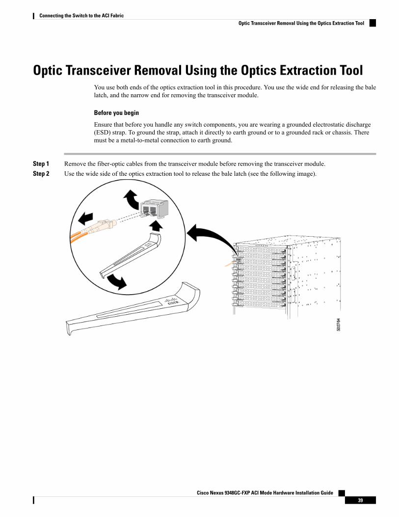
Optic Transceiver Removal Using the Optics Extraction ToolYou use both ends of the optics extraction tool in this procedure. You use the wide end for releasing the balelatch, and the narrow end for removing the transceiver module.
Before you begin
Ensure that before you handle any switch components, you are wearing a grounded electrostatic discharge(ESD) strap. To ground the strap, attach it directly to earth ground or to a grounded rack or chassis. Theremust be a metal-to-metal connection to earth ground.
Step 1 Remove the fiber-optic cables from the transceiver module before removing the transceiver module.Step 2 Use the wide side of the optics extraction tool to release the bale latch (see the following image).
Cisco Nexus 9348GC-FXP ACI Mode Hardware Installation Guide39
Connecting the Switch to the ACI FabricOptic Transceiver Removal Using the Optics Extraction Tool
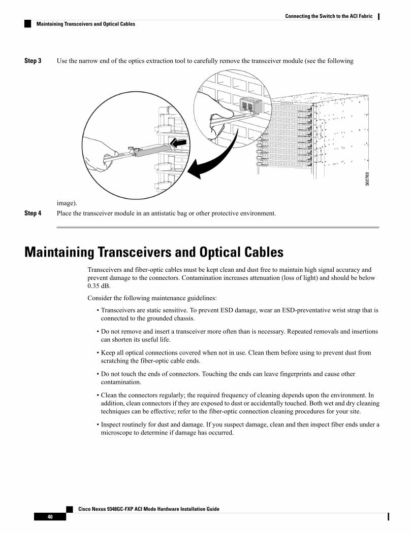
Step 3 Use the narrow end of the optics extraction tool to carefully remove the transceiver module (see the following
image).Step 4 Place the transceiver module in an antistatic bag or other protective environment.
Maintaining Transceivers and Optical CablesTransceivers and fiber-optic cables must be kept clean and dust free to maintain high signal accuracy andprevent damage to the connectors. Contamination increases attenuation (loss of light) and should be below0.35 dB.
Consider the following maintenance guidelines:
• Transceivers are static sensitive. To prevent ESD damage, wear an ESD-preventative wrist strap that isconnected to the grounded chassis.
• Do not remove and insert a transceiver more often than is necessary. Repeated removals and insertionscan shorten its useful life.
• Keep all optical connections covered when not in use. Clean them before using to prevent dust fromscratching the fiber-optic cable ends.
• Do not touch the ends of connectors. Touching the ends can leave fingerprints and cause othercontamination.
• Clean the connectors regularly; the required frequency of cleaning depends upon the environment. Inaddition, clean connectors if they are exposed to dust or accidentally touched. Both wet and dry cleaningtechniques can be effective; refer to the fiber-optic connection cleaning procedures for your site.
• Inspect routinely for dust and damage. If you suspect damage, clean and then inspect fiber ends under amicroscope to determine if damage has occurred.
Cisco Nexus 9348GC-FXP ACI Mode Hardware Installation Guide40
Connecting the Switch to the ACI FabricMaintaining Transceivers and Optical Cables
C H A P T E R 5Replacing Components
• Replacing a Fan Module, on page 41• Replacing a Power Supply Module, on page 42
Replacing a Fan ModuleYou can replace a fan module while the switch is operating so long as you perform the replacement withinone minute. If you cannot perform the replacement within one minute, leave the original fan module in thechassis to maintain the designed airflow until you have the replacement fan module on hand and can performthe replacement.
If you are replacing a module during operations, be sure that the replacement fan module has the correctdirection of airflow, which means that it has the same airflow direction as the other modules in the chassis.Also, be sure that the airflow direction takes in air from a cold aisle and exhausts to a hot aisle. Otherwise,the switch can overheat and shutdown.
If you are changing the airflow direction of all the modules in the chassis, you must shutdown the switchbefore replacing all the fan and power supply modules with modules using the other airflow direction. Duringoperations, all of the modules must have the same direction of airflow.
Caution
Removing a Fan Module
Statement 263—Fan Warning
The fans might still be turning when you remove the fan assembly from the chassis. Keep fingers, screwdrivers,and other objects away from the openings in the fan assembly's housing.
Warning
Step 1 On the fan module that you are removing, press the two sides of the fan module handle next to where it connects to thefan module and pull on the handles enough to unseat it from its connectors.
Step 2 Holding the handle, pull the module out of the chassis.
Cisco Nexus 9348GC-FXP ACI Mode Hardware Installation Guide41
Do not touch the electrical connectors on the back side of the module and prevent anything else from cominginto contact with and damaging the connectors.
Caution
Installing a Fan Module
Before you begin
• A fan slot must be open and ready for the new fan module to be installed.
• You must have a new fan module on hand and ready to install within one minute of removing the originalfan module if the switch is operating.
• The new fan module must have the same airflow direction as the other fan and power supply modulesinstalled in the switch.
Step 1 Holding the fan module by its handle, align the back of the fan module (the side with the electrical connectors) to theopen fan slot in the chassis.
Step 2 Slide the fan module into the slot until it clicks in place.Step 3 Verify that the Status (STS) LED turns on and becomes green.
Replacing a Power Supply ModuleThe switch requires two power supplies for redundancy. With one power supply providing the necessarypower for operations, you can replace the other power supply during operations so long as the new powersupply has the same airflow direction as the other modules in the chassis.
You can replace a power supply with another supported power supply that has the same power source typeand the same wattage rating as the other installed power supply. Additionally, the airflow direction of thepower supply must match or conform to the airflow direction of the installed fan modules. For the airflowdirection used by the switch, see the coloring of the fan modules.
Replacing an AC Power SupplyYou can replace an AC power supply during operations so long as the other power supply provides to theswitch.
Before you begin
You can determine the airflow direction by looking at the coloring of the latch on each power supply. ACpower supplies with burgundy latches have port-side intake airflow direction, and power supplies with bluelatches have port-side exhaust airflow direction.
Note
Cisco Nexus 9348GC-FXP ACI Mode Hardware Installation Guide42
Replacing ComponentsInstalling a Fan Module
• The replacement power supply must have the same wattage and airflow direction as the power supplybeing replaced. Do not mix AC, DC, HVAC/HVDC power supplies in the same switch.
• An AC power source must be within reach of the power cable that will be used with the replacementpower supply. If you are using n+n power redundancy, there must be a separate power source for eachpower supply installed in the chassis.
• There must be an earth ground connection to the chassis that you are installing the replacement module.AC power supplies connected to AC power sources are automatically grounded through their powercable.
Step 1 Remove an AC power supply as follows:a) Holding the plug for the power cable, pull the plug out from the power receptacle on the power supply and verify
that both power supply LEDs are off.b) Grasp the power supply handle while pressing the colored release latch towards the power supply handle.c) Place your other hand under the power supply to support it while you slide it out of the chassis.
Do not touch the electrical connections on the back side of the module and prevent anything else fromcoming into contact with and damaging the connectors.
Caution
Step 2 Install the replacement power supply as follows:a) Holding the replacement power supply with one hand underneath the module and the other hand holding the handle,
turn the power supply so that its release latch is on the right side and align the back end of the power supply (the endwith the electrical connections) to the open power supply slot before carefully sliding the power supply all the wayinto the slot until it clicks into place.
If the power supply does not fit into the open slot, turn the module over before sliding it carefully into theopen slot.
Note
b) Test the installation by trying to pull the power supply out of the slot without using the release latch.
If the power supply does not move out of place, it is secured in the slot. If the power supply moves, carefully pressit all the way into the slot until it clicks in place.
c) Attach the power cable to the electrical outlet on the front of the power supply.d) Make sure that the other end of the power cable is attached to the appropriate power source for the power supply.
Depending on the outlet receptacle on your power distribution unit, you might need the optional jumpercable to connect the switch to your outlet receptacle.
Note
e) Verify that the power supply is operational by making sure that the power supply LED is green.
Replacing a High Voltage (HVAC/HVDC) Power SupplyYou can replace an HVACHVDC power supply during operations so long as the other power supply providespower to the switch.
Cisco Nexus 9348GC-FXP ACI Mode Hardware Installation Guide43
Replacing ComponentsReplacing a High Voltage (HVAC/HVDC) Power Supply
Before you begin
• The replacement power supply must have the same wattage and airflow direction as the power supplybeing replaced. Do not mix AC, DC, HVAC/HVDC power supplies in the same switch.
• An HVAC/HVDC power source must be within reach of the power cable that will be used with thereplacement power supply. If you are using n+n power redundancy, there must be a separate power sourcefor each power supply installed in the chassis.
• There must be an earth ground connection to the chassis in which you are installing the replacementpower supply. HVAC/HVDCpower supplies connected to AC power sources are automatically groundedby their power cable when connected to the power supply and AC power source. HVAC/HVDC powersupplies connected to DC power sources have Saf-D-Grid power cables with three connectors on thepower source end--you connect one of those connectors to the earth ground.
Step 1 Remove an HVAC/HVDC power supply as follows:a) Turn off the circuit breaker for the power feed to the power supply that you are replacing.
Be sure that the LEDs turn off on the power supply that you are removing.
b) Remove the power cable from the power supply by pressing the tab on the top of the Anderson Power SAF-D-Gridconnector and pull the cable and connector out of the power supply.
c) Grasp the power supply handle while pressing the colored release latch towards the power supply handle.d) Place your other hand under the power supply to support it while you slide it out of the chassis.
Do not touch the electrical connections on the back side of the module and prevent anything else fromcoming into contact with and damaging the connectors.
Caution
Step 2 Install the replacement power supply as follows:a) Holding the replacement power supply with one hand underneath the module and the other hand holding the handle,
turn the power supply so that its release latch is on the right side and align the back end of the power supply (the endwith the electrical connections) to the open power supply slot before carefully sliding the power supply all the wayinto the slot until it clicks into place.
If the power supply does not fit into the open slot, turn the module over before sliding it carefully into theopen slot.
Note
b) Test the installation by trying to pull the power supply out of the slot without using the release latch.
If the power supply does not move out of place, it is secured in the slot. If the power supply moves, carefully pressit all the way into the slot until it clicks in place.
c) Attach the Saf-D-Grid end of the power cable to the electrical outlet on the front of the power supply.d) Make sure that the other end of the power cable is attached to the appropriate power source for the power supply.
• For an HVAC power source, plug the other end of the power cable into the power source.
• For a HVDC power source, verify that the circuit breaker is turned off and then connect each of the three cableconnectors to the appropriate DC and grounding terminals on the power source. If there is a cover plate for theDC terminals, install the plate to prevent accidental contact with the terminals.
e) If using an HVDC power source, turn on the circuit breaker for the power source.
Cisco Nexus 9348GC-FXP ACI Mode Hardware Installation Guide44
Replacing ComponentsReplacing a High Voltage (HVAC/HVDC) Power Supply
f) Verify that the power supply is operational by making sure that the power supply LED is green.
Replacing a DC Power SupplyYou can replace an DC power supply during operations so long as the other power supply provides power tothe switch.
Before you begin
• The replacement power supply must have the same wattage and airflow direction as the power supplybeing replaced. Do not mix AC, DC, HVAC/HVDC power supplies in the same switch.
You can determine the airflow direction by looking at the coloringof the latch on each power supply. AC power supplies with burgundylatches have port-side intake airflow direction, and power supplieswith blue latches have port-side exhaust airflow direction.
Note
• An DC power source must be within reach of the power cables that will be used with the replacementpower supply. If you are using n+n power redundancy, there must be a separate power source for eachpower supply installed in the chassis.
• There must be an earth ground connection to the chassis in which you are installing the replacementpower supply. DC power supplies connected to DC power sources have three power cables (two for DCpower and one for grounding).
• We recommend 8-AWG wire for DC installation in the U.S.
• All DC power supplies have reverse polarity protection.When you inadvertently connect the input power(+) to the DC PSU’s – terminal and the input power – to the DC PSU’s (+) terminal, the PSU will notbe damaged and will operate fine after the input power feeds are correctly wired.
Step 1 Remove a DC power supply as follows:a) Turn off the circuit breaker for the power feed to the power supply that you are replacing.
Be sure that the LEDs turn off on the power supply that you are removing.
b) Remove the DC power connector block from the power supply by doing the following:
1. Push the orange plastic button on the top of the connector block inward toward the power supply.
2. Pull the connector block out of the power supply.
c) Grasp the power supply handle while pressing the release latch towards the power supply handle.d) Place your other hand under the power supply to support it while you slide it out of the chassis.
Do not touch the electrical connections on the back side of the module and prevent anything else fromcoming into contact with and damaging the connectors.
Caution
Cisco Nexus 9348GC-FXP ACI Mode Hardware Installation Guide45
Replacing ComponentsReplacing a DC Power Supply
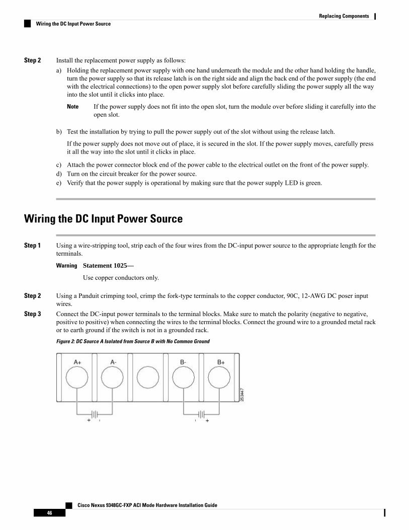
Step 2 Install the replacement power supply as follows:a) Holding the replacement power supply with one hand underneath the module and the other hand holding the handle,
turn the power supply so that its release latch is on the right side and align the back end of the power supply (the endwith the electrical connections) to the open power supply slot before carefully sliding the power supply all the wayinto the slot until it clicks into place.
If the power supply does not fit into the open slot, turn the module over before sliding it carefully into theopen slot.
Note
b) Test the installation by trying to pull the power supply out of the slot without using the release latch.
If the power supply does not move out of place, it is secured in the slot. If the power supply moves, carefully pressit all the way into the slot until it clicks in place.
c) Attach the power connector block end of the power cable to the electrical outlet on the front of the power supply.d) Turn on the circuit breaker for the power source.e) Verify that the power supply is operational by making sure that the power supply LED is green.
Wiring the DC Input Power Source
Step 1 Using a wire-stripping tool, strip each of the four wires from the DC-input power source to the appropriate length for theterminals.
Statement 1025—
Use copper conductors only.
Warning
Step 2 Using a Panduit crimping tool, crimp the fork-type terminals to the copper conductor, 90C, 12-AWG DC poser inputwires.
Step 3 Connect the DC-input power terminals to the terminal blocks. Make sure to match the polarity (negative to negative,positive to positive) when connecting the wires to the terminal blocks. Connect the ground wire to a grounded metal rackor to earth ground if the switch is not in a grounded rack.
Figure 2: DC Source A Isolated from Source B with No Common Ground
Cisco Nexus 9348GC-FXP ACI Mode Hardware Installation Guide46
Replacing ComponentsWiring the DC Input Power Source
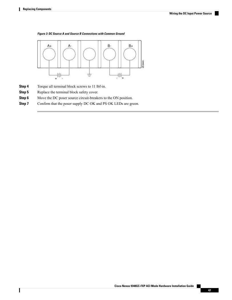
Figure 3: DC Source A and Source B Connections with Common Ground
Step 4 Torque all terminal block screws to 11 lbf-in.Step 5 Replace the terminal block safety cover.Step 6 Move the DC poser source circuit-breakers to the ON position.Step 7 Confirm that the poser supply DC OK and PS OK LEDs are green.
Cisco Nexus 9348GC-FXP ACI Mode Hardware Installation Guide47
Replacing ComponentsWiring the DC Input Power Source

Cisco Nexus 9348GC-FXP ACI Mode Hardware Installation Guide48
Replacing ComponentsWiring the DC Input Power Source
A P P E N D I X ARack Specifications
• Overview of Racks, on page 49• General Requirements for Cabinets and Racks, on page 49• Requirements Specific to Standard Open Racks, on page 50• Requirements Specific to Perforated Cabinets, on page 50• Cable Management Guidelines, on page 51
Overview of RacksYou can install the switch in the following types of cabinets and racks, assuming an external ambient airtemperature range of 0 to 104°F (0 to 40°C):
• Standard perforated cabinets
• Solid-walled cabinets with a roof fan tray (bottom to top cooling)
• Standard open racks
If you are selecting an enclosed cabinet, we recommend one of the thermally validated types, either standardperforated or solid-walled with a fan tray.
Note
We do not recommend that you use racks that have obstructions (such as power strips), because the obstructionscould impair access to field-replaceable units (FRUs).
Note
General Requirements for Cabinets and RacksThe cabinet or rack must also meet the following requirements:
• Standard 19-inch (48.3 cm) (two- or four-post EIA cabinet or rack, with mounting rails that conform toEnglish universal hole spacing per section 1 of ANSI/EIA-310-D-1992). For more information, seeRequirements Specific to Perforated Cabinets, on page 50.
Cisco Nexus 9348GC-FXP ACI Mode Hardware Installation Guide49

• The minimum vertical rack space requirement per chassis is:
• For a one RU (rack unit) switch, 1.75 inches (4.4 cm)
• For a one and a half RU (rack unit) switch, 2.63 (6.68 cm)
• For a two RU (rack unit) switch, 3.5 inches (8.8 cm)
• For a three RU (rack unit) switch, 5.25 inches (13.3 cm)
• The width between the rack-mounting rails must be at least 17.75 inches (45.0 cm) if the rear of thedevice is not attached to the rack. For four-post EIA racks, this measurement is the distance between thetwo front rails.
Four-post EIA cabinets (perforated or solid-walled) must meet the following requirements:
• The minimum spacing for the bend radius for fiber-optic cables should have the front-mounting rails ofthe cabinet offset from the front door by a minimum of 3 inches (7.6 cm).
• The distance between the outside face of the front mounting rail and the outside face of the back mountingrail should be 23.0 to 30.0 inches (58.4 to 76.2 cm) to allow for rear-bracket installation.
For the specific rack dimension information for each possible rack-mount, see Installation Options withRack-Mount Kits, on page 14.
Requirements Specific to Standard Open RacksIf you are mounting the chassis in an open rack (no side panels or doors), ensure that the rack meets thefollowing requirements:
• The minimum vertical rack space per chassis must be equal to the rack unit (RU) of the chassis. Onerack unit is equal to 1.75 inches (4.4 cm).
• The distance between the chassis air vents and any walls should be 2.5 inches (6.4 cm).
Requirements Specific to Perforated CabinetsA perforated cabinet has perforations in its front and rear doors and side walls. Perforated cabinets must meetthe following requirements:
• The front and rear doors must have at least a 60 percent open area perforation pattern, with at least 15square inches (96.8 square cm) of open area per rack unit of door height.
• The roof should be perforated with at least a 20 percent open area.
• The cabinet floor should be open or perforated to enhance cooling.
The Cisco R Series rack conforms to these requirements.
Cisco Nexus 9348GC-FXP ACI Mode Hardware Installation Guide50
Rack SpecificationsRequirements Specific to Standard Open Racks
Cable Management GuidelinesTo help with cable management, you might want to allow additional space in the rack above and below thechassis to make it easier to route all of the fiber optic or copper cables through the rack.
Cisco Nexus 9348GC-FXP ACI Mode Hardware Installation Guide51
Rack SpecificationsCable Management Guidelines

Cisco Nexus 9348GC-FXP ACI Mode Hardware Installation Guide52
Rack SpecificationsCable Management Guidelines
A P P E N D I X BSystem Specifications
• Environmental Specifications, on page 53• Switch Dimensions, on page 53• Switch and Module Weights and Quantities, on page 54• Transceiver and Cable Specifications, on page 54• Switch Power Input Requirements, on page 54• Power Specifications, on page 55• Power Cable Specifications, on page 57• Regulatory Standards Compliance Specifications, on page 58
Environmental SpecificationsSpecificationEnvironment
32 to 104°F (0 to 40°C)Ambient operating temperatureTemperature
–40 to 158°F (–40 to 70°C)Ambient nonoperating
5 to 85%NonoperatingRelativehumidity
0 to 13,123 feet (0 to 4,000 meters)OperatingAltitude
Switch DimensionsHeightDepthWidthSwitch
1.72 inches (4.4 cm) (1 RU)With AC powersupplies 19.7 inches(49.9 cm).
With DC powersupplies 21.0 inches(53.34 cm).
17.3 inches (43.9 cm)Cisco Nexus 9348GC-FXP
Cisco Nexus 9348GC-FXP ACI Mode Hardware Installation Guide53
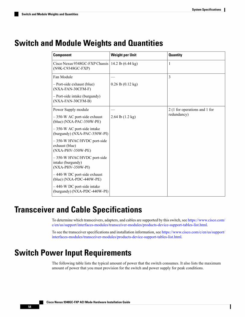
Switch and Module Weights and QuantitiesQuantityWeight per UnitComponent
114.2 lb (6.44 kg)CiscoNexus 9348GC-FXPChassis(N9K-C9348GC-FXP)
3—
0.26 lb (0.12 kg)
Fan Module
– Port-side exhaust (blue)(NXA-FAN-30CFM-F)
– Port-side intake (burgundy)(NXA-FAN-30CFM-B)
2 (1 for operations and 1 forredundancy)
—
2.64 lb (1.2 kg)
Power Supply module
– 350-W AC port-side exhaust(blue) (NXA-PAC-350W-PE)
– 350-W AC port-side intake(burgundy) (NXA-PAC-350W-PI)
– 350-W HVAC/HVDC port-sideexhaust (blue)(NXA-PHV-350W-PE)
– 350-W HVAC/HVDC port-sideintake (burgundy)(NXA-PHV-350W-PI)
– 440-W DC port-side exhaust(blue) (NXA-PDC-440W-PE)
– 440-W DC port-side intake(burgundy) (NXA-PDC-440W-PI)
Transceiver and Cable SpecificationsTo determine which transceivers, adapters, and cables are supported by this switch, see https://www.cisco.com/c/en/us/support/interfaces-modules/transceiver-modules/products-device-support-tables-list.html.
To see the transceiver specifications and installation information, see https://www.cisco.com/c/en/us/support/interfaces-modules/transceiver-modules/products-device-support-tables-list.html.
Switch Power Input RequirementsThe following table lists the typical amount of power that the switch consumes. It also lists the maximumamount of power that you must provision for the switch and power supply for peak conditions.
Cisco Nexus 9348GC-FXP ACI Mode Hardware Installation Guide54
System SpecificationsSwitch and Module Weights and Quantities
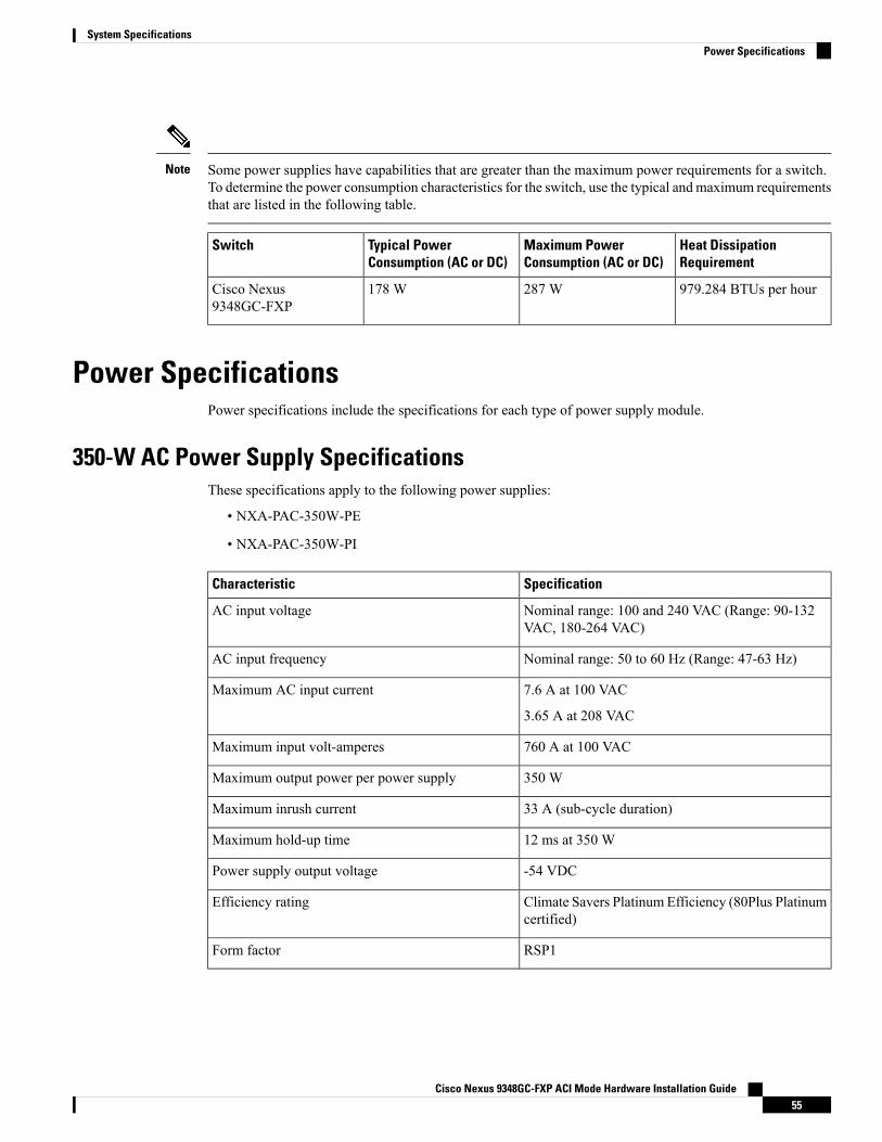
Some power supplies have capabilities that are greater than the maximum power requirements for a switch.To determine the power consumption characteristics for the switch, use the typical and maximum requirementsthat are listed in the following table.
Note
Heat DissipationRequirement
Maximum PowerConsumption (AC or DC)
Typical PowerConsumption (AC or DC)
Switch
979.284 BTUs per hour287 W178 WCisco Nexus9348GC-FXP
Power SpecificationsPower specifications include the specifications for each type of power supply module.
350-W AC Power Supply SpecificationsThese specifications apply to the following power supplies:
• NXA-PAC-350W-PE
• NXA-PAC-350W-PI
SpecificationCharacteristic
Nominal range: 100 and 240 VAC (Range: 90-132VAC, 180-264 VAC)
AC input voltage
Nominal range: 50 to 60 Hz (Range: 47-63 Hz)AC input frequency
7.6 A at 100 VAC
3.65 A at 208 VAC
Maximum AC input current
760 A at 100 VACMaximum input volt-amperes
350 WMaximum output power per power supply
33 A (sub-cycle duration)Maximum inrush current
12 ms at 350 WMaximum hold-up time
-54 VDCPower supply output voltage
Climate Savers Platinum Efficiency (80Plus Platinumcertified)
Efficiency rating
RSP1Form factor
Cisco Nexus 9348GC-FXP ACI Mode Hardware Installation Guide55
System SpecificationsPower Specifications

350-W PHV Power Supply SpecificationsThese specifications apply to the following power supplies:
• NXA-PHV-350W-PE
• NXA-PHV-350W-PI
SpecificationCharacteristic
192 to 400 VDC
90 to 305 VAC
Input voltage
Nominal range: 50 to 60 Hz (Range: 47-63 Hz)Input frequency
350 WMaximum output power per power supply
-54 VDCPower supply output voltage
Climate Savers Platinum Efficiency (80Plus Platinumcertified)
Efficiency rating
RSP1Form factor
440-W DC Power Supply SpecificationsThese specifications apply to the following power supplies:
• NXA-PDC-440W-PE
• NXA-PDC-440W-PI
SpecificationCharacteristic
440 WMaximum output power
16 -8 AInput current
-36 to -72 VDCDC input voltage
-56 [email protected] AOutput ratings
-36 VDC (minimum), -48 VDC (nominal), -72 VDC(maximum)
Voltage range domestic
-36 VDC (minimum), -48 VDC (nominal), -72 VDC(maximum)
Voltage range international
1841 BTUs per hour, 540 WTotal input BTU1
1502 BTUs per hour, 440 WTotal output BTU2
20 ABranch circuit protection
Cisco Nexus 9348GC-FXP ACI Mode Hardware Installation Guide56
System Specifications350-W PHV Power Supply Specifications
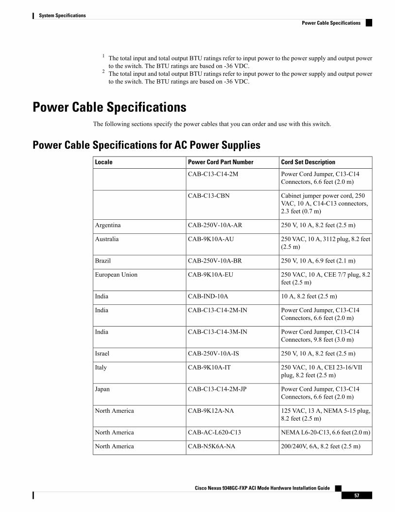
1 The total input and total output BTU ratings refer to input power to the power supply and output powerto the switch. The BTU ratings are based on -36 VDC.
2 The total input and total output BTU ratings refer to input power to the power supply and output powerto the switch. The BTU ratings are based on -36 VDC.
Power Cable SpecificationsThe following sections specify the power cables that you can order and use with this switch.
Power Cable Specifications for AC Power SuppliesCord Set DescriptionPower Cord Part NumberLocale
Power Cord Jumper, C13-C14Connectors, 6.6 feet (2.0 m)
CAB-C13-C14-2M
Cabinet jumper power cord, 250VAC, 10 A, C14-C13 connectors,2.3 feet (0.7 m)
CAB-C13-CBN
250 V, 10 A, 8.2 feet (2.5 m)CAB-250V-10A-ARArgentina
250 VAC, 10 A, 3112 plug, 8.2 feet(2.5 m)
CAB-9K10A-AUAustralia
250 V, 10 A, 6.9 feet (2.1 m)CAB-250V-10A-BRBrazil
250 VAC, 10 A, CEE 7/7 plug, 8.2feet (2.5 m)
CAB-9K10A-EUEuropean Union
10 A, 8.2 feet (2.5 m)CAB-IND-10AIndia
Power Cord Jumper, C13-C14Connectors, 6.6 feet (2.0 m)
CAB-C13-C14-2M-INIndia
Power Cord Jumper, C13-C14Connectors, 9.8 feet (3.0 m)
CAB-C13-C14-3M-INIndia
250 V, 10 A, 8.2 feet (2.5 m)CAB-250V-10A-ISIsrael
250 VAC, 10 A, CEI 23-16/VIIplug, 8.2 feet (2.5 m)
CAB-9K10A-ITItaly
Power Cord Jumper, C13-C14Connectors, 6.6 feet (2.0 m)
CAB-C13-C14-2M-JPJapan
125 VAC, 13 A, NEMA 5-15 plug,8.2 feet (2.5 m)
CAB-9K12A-NANorth America
NEMAL6-20-C13, 6.6 feet (2.0m)CAB-AC-L620-C13North America
200/240V, 6A, 8.2 feet (2.5 m)CAB-N5K6A-NANorth America
Cisco Nexus 9348GC-FXP ACI Mode Hardware Installation Guide57
System SpecificationsPower Cable Specifications
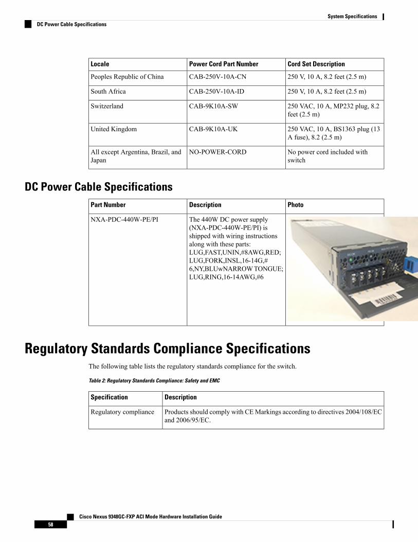
Cord Set DescriptionPower Cord Part NumberLocale
250 V, 10 A, 8.2 feet (2.5 m)CAB-250V-10A-CNPeoples Republic of China
250 V, 10 A, 8.2 feet (2.5 m)CAB-250V-10A-IDSouth Africa
250 VAC, 10 A, MP232 plug, 8.2feet (2.5 m)
CAB-9K10A-SWSwitzerland
250 VAC, 10 A, BS1363 plug (13A fuse), 8.2 (2.5 m)
CAB-9K10A-UKUnited Kingdom
No power cord included withswitch
NO-POWER-CORDAll except Argentina, Brazil, andJapan
DC Power Cable SpecificationsPhotoDescriptionPart Number
The 440W DC power supply(NXA-PDC-440W-PE/PI) isshipped with wiring instructionsalong with these parts:LUG,FAST,UNIN,#8AWG,RED;LUG,FORK,INSL,16-14G,#6,NY,BLUwNARROWTONGUE;LUG,RING,16-14AWG,#6
NXA-PDC-440W-PE/PI
Regulatory Standards Compliance SpecificationsThe following table lists the regulatory standards compliance for the switch.
Table 2: Regulatory Standards Compliance: Safety and EMC
DescriptionSpecification
Products should comply with CEMarkings according to directives 2004/108/ECand 2006/95/EC.
Regulatory compliance
Cisco Nexus 9348GC-FXP ACI Mode Hardware Installation Guide58
System SpecificationsDC Power Cable Specifications
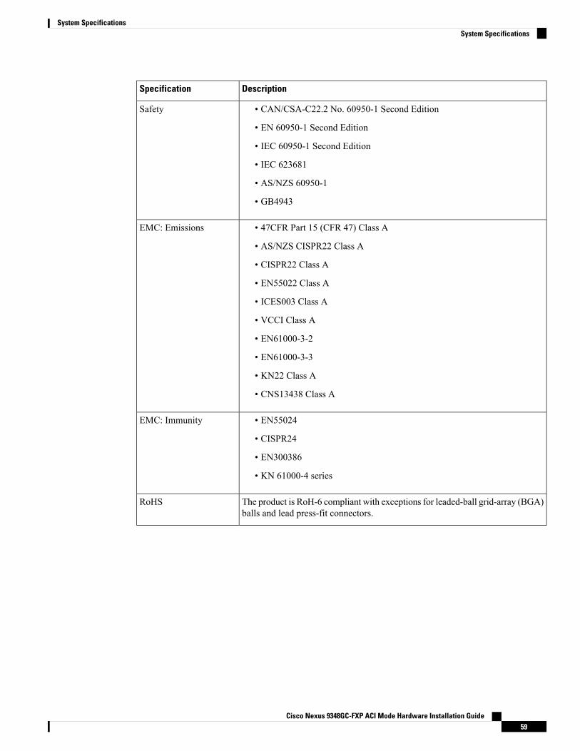
DescriptionSpecification
• CAN/CSA-C22.2 No. 60950-1 Second Edition
• EN 60950-1 Second Edition
• IEC 60950-1 Second Edition
• IEC 623681
• AS/NZS 60950-1
• GB4943
Safety
• 47CFR Part 15 (CFR 47) Class A
• AS/NZS CISPR22 Class A
• CISPR22 Class A
• EN55022 Class A
• ICES003 Class A
• VCCI Class A
• EN61000-3-2
• EN61000-3-3
• KN22 Class A
• CNS13438 Class A
EMC: Emissions
• EN55024
• CISPR24
• EN300386
• KN 61000-4 series
EMC: Immunity
The product is RoH-6 compliant with exceptions for leaded-ball grid-array (BGA)balls and lead press-fit connectors.
RoHS
Cisco Nexus 9348GC-FXP ACI Mode Hardware Installation Guide59
System SpecificationsSystem Specifications

Cisco Nexus 9348GC-FXP ACI Mode Hardware Installation Guide60
System SpecificationsSystem Specifications
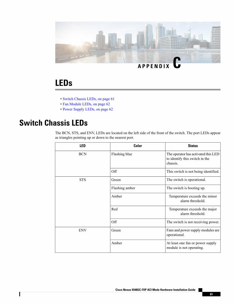
A P P E N D I X CLEDs
• Switch Chassis LEDs, on page 61• Fan Module LEDs, on page 62• Power Supply LEDs, on page 62
Switch Chassis LEDsThe BCN, STS, and ENV, LEDs are located on the left side of the front of the switch. The port LEDs appearas triangles pointing up or down to the nearest port.
StatusColorLED
The operator has activated this LEDto identify this switch in thechassis.
Flashing blueBCN
This switch is not being identified.Off
The switch is operational.GreenSTS
The switch is booting up.Flashing amber
Temperature exceeds the minoralarm threshold.
Amber
Temperature exceeds the majoralarm threshold.
Red
The switch is not receiving power.Off
Fans and power supplymodules areoperational.
GreenENV
At least one fan or power supplymodule is not operating.
Amber
Cisco Nexus 9348GC-FXP ACI Mode Hardware Installation Guide61
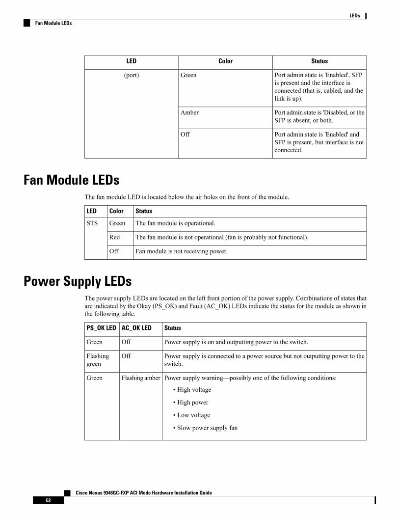
StatusColorLED
Port admin state is 'Enabled', SFPis present and the interface isconnected (that is, cabled, and thelink is up).
Green(port)
Port admin state is 'Disabled, or theSFP is absent, or both.
Amber
Port admin state is 'Enabled' andSFP is present, but interface is notconnected.
Off
Fan Module LEDsThe fan module LED is located below the air holes on the front of the module.
StatusColorLED
The fan module is operational.GreenSTS
The fan module is not operational (fan is probably not functional).Red
Fan module is not receiving power.Off
Power Supply LEDsThe power supply LEDs are located on the left front portion of the power supply. Combinations of states thatare indicated by the Okay (PS_OK) and Fault (AC_OK) LEDs indicate the status for the module as shown inthe following table.
StatusAC_OK LEDPS_OK LED
Power supply is on and outputting power to the switch.OffGreen
Power supply is connected to a power source but not outputting power to theswitch.
OffFlashinggreen
Power supply warning—possibly one of the following conditions:
• High voltage
• High power
• Low voltage
• Slow power supply fan
Flashing amberGreen
Cisco Nexus 9348GC-FXP ACI Mode Hardware Installation Guide62
LEDsFan Module LEDs

StatusAC_OK LEDPS_OK LED
Rotor fault
This behavior occurs if the fan rotor is stopped during normal switchoperation.
Note
AmberGreen
AC cord that is removedwhile in redundant mode (while other PSU is running).AmberOff
Cisco Nexus 9348GC-FXP ACI Mode Hardware Installation Guide63
LEDsLEDs

Cisco Nexus 9348GC-FXP ACI Mode Hardware Installation Guide64
LEDsLEDs
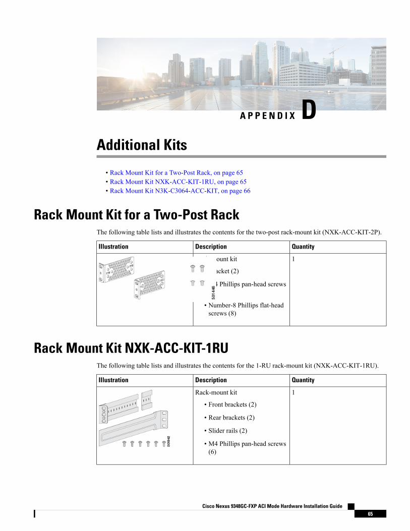
A P P E N D I X DAdditional Kits
• Rack Mount Kit for a Two-Post Rack, on page 65• Rack Mount Kit NXK-ACC-KIT-1RU, on page 65• Rack Mount Kit N3K-C3064-ACC-KIT, on page 66
Rack Mount Kit for a Two-Post RackThe following table lists and illustrates the contents for the two-post rack-mount kit (NXK-ACC-KIT-2P).
QuantityDescriptionIllustration
1Rack-mount kit
• Bracket (2)
• M4 Phillips pan-head screws(4)
• Number-8 Phillips flat-headscrews (8)
Rack Mount Kit NXK-ACC-KIT-1RUThe following table lists and illustrates the contents for the 1-RU rack-mount kit (NXK-ACC-KIT-1RU).
QuantityDescriptionIllustration
1Rack-mount kit
• Front brackets (2)
• Rear brackets (2)
• Slider rails (2)
• M4 Phillips pan-head screws(6)
Cisco Nexus 9348GC-FXP ACI Mode Hardware Installation Guide65
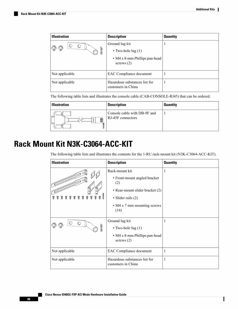
QuantityDescriptionIllustration
1Ground lug kit
• Two-hole lug (1)
• M4 x 8-mm Phillips pan-headscrews (2)
1EAC Compliance documentNot applicable
1Hazardous substances list forcustomers in China
Not applicable
The following table lists and illustrates the console cable (CAB-CONSOLE-RJ45) that can be ordered.
QuantityDescriptionIllustration
1Console cable with DB-9F andRJ-45F connectors
Rack Mount Kit N3K-C3064-ACC-KITThe following table lists and illustrates the contents for the 1-RU rack-mount kit (N3K-C3064-ACC-KIT).
QuantityDescriptionIllustration
1Rack-mount kit
• Front-mount angled bracket(2)
• Rear-mount slider bracket (2)
• Slider rails (2)
• M4 x 7 mm mounting screws(16)
1Ground lug kit
• Two-hole lug (1)
• M4 x 8-mm Phillips pan-headscrews (2)
1EAC Compliance documentNot applicable
1Hazardous substances list forcustomers in China
Not applicable
Cisco Nexus 9348GC-FXP ACI Mode Hardware Installation Guide66
Additional KitsRack Mount Kit N3K-C3064-ACC-KIT
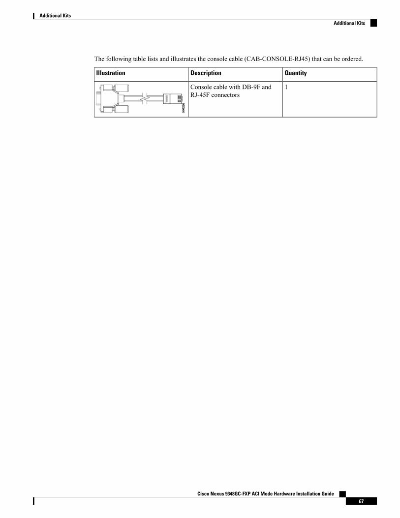
The following table lists and illustrates the console cable (CAB-CONSOLE-RJ45) that can be ordered.
QuantityDescriptionIllustration
1Console cable with DB-9F andRJ-45F connectors
Cisco Nexus 9348GC-FXP ACI Mode Hardware Installation Guide67
Additional KitsAdditional Kits

Cisco Nexus 9348GC-FXP ACI Mode Hardware Installation Guide68
Additional KitsAdditional Kits
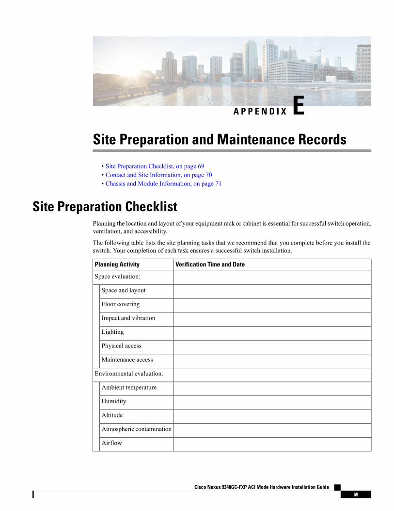
A P P E N D I X ESite Preparation and Maintenance Records
• Site Preparation Checklist, on page 69• Contact and Site Information, on page 70• Chassis and Module Information, on page 71
Site Preparation ChecklistPlanning the location and layout of your equipment rack or cabinet is essential for successful switch operation,ventilation, and accessibility.
The following table lists the site planning tasks that we recommend that you complete before you install theswitch. Your completion of each task ensures a successful switch installation.
Verification Time and DatePlanning Activity
Space evaluation:
Space and layout
Floor covering
Impact and vibration
Lighting
Physical access
Maintenance access
Environmental evaluation:
Ambient temperature
Humidity
Altitude
Atmospheric contamination
Airflow
Cisco Nexus 9348GC-FXP ACI Mode Hardware Installation Guide69
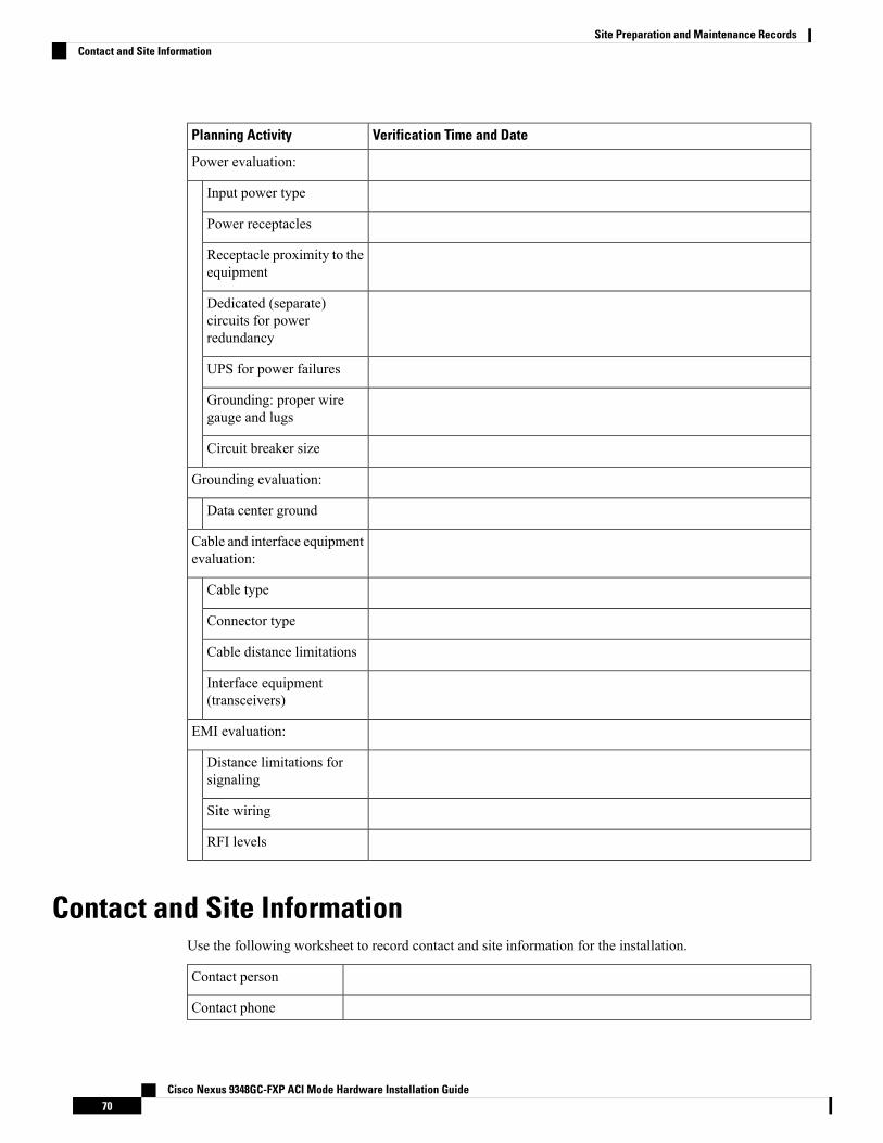
Verification Time and DatePlanning Activity
Power evaluation:
Input power type
Power receptacles
Receptacle proximity to theequipment
Dedicated (separate)circuits for powerredundancy
UPS for power failures
Grounding: proper wiregauge and lugs
Circuit breaker size
Grounding evaluation:
Data center ground
Cable and interface equipmentevaluation:
Cable type
Connector type
Cable distance limitations
Interface equipment(transceivers)
EMI evaluation:
Distance limitations forsignaling
Site wiring
RFI levels
Contact and Site InformationUse the following worksheet to record contact and site information for the installation.
Contact person
Contact phone
Cisco Nexus 9348GC-FXP ACI Mode Hardware Installation Guide70
Site Preparation and Maintenance RecordsContact and Site Information

Contact e-mail
Building/site name
Data center location
Floor location
Address (line 1)
Address (line 2)
City
State/Provence
Contact person
ZIP/postal code
Country
Chassis and Module InformationUse the following worksheet to record information about the switch.
Contract number
Chassis serial number
Product number
Use the following worksheet to record network-related information.
Switch IP address
Switch IP netmask
Hostname
Domain name
IP broadcast address
Gateway/router address
DNS address
Use the following worksheet to record information about the modules in the switch.
NotesModule Serial NumberModule TypeModule Slot
Fan module 1
Cisco Nexus 9348GC-FXP ACI Mode Hardware Installation Guide71
Site Preparation and Maintenance RecordsChassis and Module Information
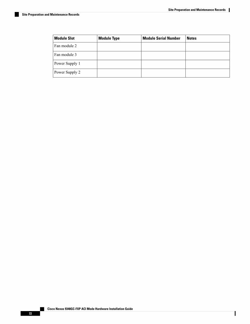
NotesModule Serial NumberModule TypeModule Slot
Fan module 2
Fan module 3
Power Supply 1
Power Supply 2
Cisco Nexus 9348GC-FXP ACI Mode Hardware Installation Guide72
Site Preparation and Maintenance RecordsSite Preparation and Maintenance Records