cislunar tether transport · pdf fileusing numerical simulations that incorporate the full...
TRANSCRIPT

AIAA-99-2690
CISLUNAR TETHER TRANSPORT SYSTEM Robert P. Hoyt*
Tethers Unlimited, Inc., Seattle, Washington 98125-3236 USA Chauncey Uphoff†
Fortune Eight Aerospace, Niwot, Colorado 80544 USA
Abstract We describe a space systems architecture for repeatedly transporting payloads between low
Earth orbit and the surface of the moon without significant use of propellant. This architecture consists of one rotating tether in elliptical, equatorial Earth orbit and a second rotating tether in a circular low lunar orbit. The Earth-orbit tether picks up a payload from a circular low Earth orbit and tosses it into a minimal-energy lunar transfer orbit. When the payload arrives at the Moon, the lunar tether catches it and deposits it on the surface of the Moon. Simultaneously, the lunar tether picks up a lunar payload to be sent down to the Earth orbit tether. By transporting equal masses to and from the Moon, the orbital energy and momentum of the system can be conserved, eliminating the need for transfer propellant. Using currently available high-strength tether materials, this system could be built with a total mass of less than 28 times the mass of the payloads it can transport. Using numerical simulations that incorporate the full three-dimensional orbital mechanics and tether dynamics, we have verified the feasibility of this system architecture and developed scenarios for transferring a payload from a low Earth orbit to the surface of the Moon that require less than 25 m/s of thrust for trajectory targeting corrections.
Nomenclature & Units a semimajor axis, m C3 orbital energy, ! V2 - 2µ/r , km2/s2 d density, kg/m3 e ellipse eccentricity E orbital energy, J F safety factor h specific angular momentum, m2/s i orbit inclination, degrees J2 2nd geopotential coefficient L tether arm length, m l distance from facility to system’s center of mass. M mass, kg N orbital resonance parameter p orbit semiparameter, = a(1-e2) , m r radius, m Re Earth radius, m rp perigee radius, m T tensile strength, Pa V velocity, m/s VC characteristic velocity, m/s " argument of tether perigee w.r.t. Earth-Moon line µe Earth’s gravitational parameter = GMe, m
3/s2 µm Moon’s gravitational parameter = GMm, m3/s2
# angular velocity, radians/s $ true anomaly ˙ ! Apsidal precession/regression rate, rad/s ˙ ! Nodal regression rate, radians/s
subscripts:
!a apoapse !p periapse
!c critical !m moon !f facility !g grapple
!P payload !t tether
Introduction A “Cislunar Tether Transport System” composed of one rotating momentum-exchange tether in elliptical, equatorial Earth orbit and a second rotating tether facility in a low lunar orbit can provide a means for repeatedly exchanging payloads between low Earth orbit (LEO) and the surface of the Moon, with little or no propellant expenditure required. In 1991, Forward1 showed that such a system is theoretically possible from an energetics standpoint. A later study by Hoyt and Forward2 developed a first-order design for such a system. These previous studies, however, utilized a number of simplifying assumptions regarding orbital and tether mechanics in the Earth-Moon system, including assumptions of coplanar orbits, ideal gravitational potentials, and infinite facility ballast masses. The purpose of this paper is to remove these assumptions and develop an architecture for such a system that takes into account the complexities of orbital mechanics in the Earth-Moon system.
The basic concept of the Cislunar Tether Transport System is to use a rotating tether in Earth orbit to pick payloads up from LEO orbits and toss them to the Moon, where a rotating tether in lunar orbit, called a “Lunavator™”, could catch them and deliver them to the lunar surface. As the Lunavator™ delivers payloads to the Moon’s surface, it can also pick up return payloads, such as water or aluminum processed from lunar resources, and send them down to LEO. By balancing the flow of mass to and from the Moon, the orbital momentum and energy of the system * President, CEO, & Chief Engineer, 1917 NE 143
rd St.,
Seattle WA 98125-3236, Member AIAA. † Chief Scientist, P.O. Box 307 Niwot, CO 80544. Copyright © 1999 by Tethers Unlimited, Inc. Published by the American Institute of Aeronautics and Astronautics with permission.

Cislunar Tether Transport System AIAA-99-2690
2
can be conserved, eliminating the need to expend large quantities of propellant to move the payloads back and forth. This system is illustrated in Figure 1.
Orbital Mechanics of the Earth-Moon System Orbital mechanics in cislunar space are made quite complex by the different and varying orientations of the ecliptic plane, the Earth’s equatorial plane, the Moon’s orbital plane, and the Moon’s equatorial plane. Figure 2 attempts to illustrate these different planes. The inclination of the Earth’s equatorial plane (the “obliquity of the ecliptic”), is approximately 23.45°, but varies due to tidal forces exerted by the Sun and Moon. The angle im between the Moon’s equatorial plane and a plane through the Moon’s center that is parallel to the ecliptic plane is constant, about 1.58°. The inclination of the Moon’s orbit relative to the
ecliptic plane is also constant, about "m = 5.15°.3 The line of nodes of the Moon’s orbit regresses slowly, revolving once every 18.6 years. As a result, the inclination of the Moon’s orbit relative to the Earth’s equator varies between 18.3-28.6 degrees. The Moon’s orbit also has a slight eccentricity, approximately em = 0.0549.
Tether Orbits After considering many different options, including the three-tether systems proposed pre-viously and various combinations of elliptical and circular orbits, we have determined that the optimum configuration for the Cislunar Tether system is to utilize one tether in an elliptical, equatorial Earth orbit and one tether in a polar, circular lunar orbit, as illustrated in Figure 1. This two-tether system will require the lowest total system mass, minimize the system complexity and provide the most frequent transfer opportunities. The Earth-orbit tether will pick payloads up from
equatorial low-LEO orbits and throw them towards one of the two points where the Moon crosses the Earth’s equatorial plane. As the payload approaches the Moon, it will need to perform a small !V maneuver to set it up into the proper approach trajectory; the size of this maneuver will vary depending upon the inclination of the Moon’s orbit plane and launch dispersions, but under most conditions it will only require about 25 m/s of !V.
In the following sections, we will first develop a design for a tether facility for boosting payloads from low-LEO orbits to lunar transfer orbits (LTO). We will then develop a design for a “Lunavator™” capable of catching the payloads and delivering them to the surface of the Moon. We will then discuss the numerical simulations used to verify the feasibility of this system architecture.
Design of a Tether Boost Facility for Lunar Transfer Injection
The first stage of the Cislunar Tether Transport System will be a tether boost facility in elliptical Earth orbit capable of picking payloads up from low-LEO orbits and tossing them to the Moon. In order to determine an optimum configuration for this facility, we must balance the need to minimize the required masses of the tethers and facilities with the need to make the orbital dynamics of the system as manageable as possible.
The mission of the Earth-orbit portion of the Cislunar Tether Transport System is to pick up a payload from low-Earth orbit and inject it into a near-minimum energy lunar transfer orbit. The desired lunar transfer trajectories have a C3 of approximately –1.9 (km/s)2. A payload orig-
Figure 1. Conceptual illustration of the Cislunar Tether Transport System.
To sun
Earth's
Equatorial
Plane
Moon's
Equatorial
Plane
Ecliptic
Moon's
Orbit
ie
im
!m
Figure 2. Schematic illustrating the geometry of the Earth-Moon system.

Cislunar Tether Transport System AIAA-99-2690
3
inating in a circular orbit at 350 km altitude has an initial velocity of 7.7 km/s and a C3 of –60 (km/s)2. To impulsively inject the payload into a trajectory with a C3 of –1.9 would require a !V of approximately 3.1 km/s.
Design Considerations Tether System Staging From an operational standpoint, the most convenient design for the Earth-orbit portion of a Cislunar Tether Transport System would be to start with a single tether facility in a circular low-Earth-orbit, with the tether retracted. The facility would rendezvous with the payload, deploy the payload at the end of the tether, and then use propellantless electrodynamic tether propulsion to spin up the tether until the tip speed reached 3.1 km/s and the tether could inject the payload into a LTO. However, because the tether transfers some of its orbital momentum and energy to the payload when it boosts it, a tether facility in circular orbit would require a very large ballast mass so that its orbit would not drop into the upper atmosphere after it boosts a payload. Furthermore, the strong dependence of the required tether mass on the tether tip speed will likely make this approach impractical with current material technologies. The required mass for a tapered tether depends upon the tip mass and the ratio of the tip velocity to the tether material’s critical velocity according to the relation derived by Moravec:4
Mt = Mp !"V
VCe
"V 2
VC2
erf"V
VC
# $ %
& ' (
, (1)
where erf() is the error function. The critical velocity of a tether material depends upon the tensile strength, the material density, and the design safety factor according to:
VC=
2T
Fd. (2)
The exponential dependence of the tether mass on the square of the velocity ratio results in a very rapid increase in tether mass with this ratio.
Currently, the best commercially-available tether material is Spectra® 2000, a form of highly oriented polyethlene manufactured by Allied-Signal. High-quality specimens of Spectra® 2000 have a room temperature tensile strength of 4 GPa, and a density of 0.97 g/cc. With a safety factor of 3, the material’s critical velocity is 1.66 km/s. Using Equation (1), an optimally-tapered Spectra® tether capable of sustaining a tip velocity of 3.1 km/s would require a mass of over 100 times the payload mass. While this might be technically
feasible for very small payloads, such a large tether mass probably would not be economically competitive with rocket technologies. In the future, very high strength materials such as “buckytube” yarns may become available with tensile strengths that will make a 3 km/s tether feasible; however, we will show that a different approach to the system architecture can utilize currently available materials to perform the mission with reasonable mass requirements.
The tether mass is reduced to reasonable levels if the !V/Vc ratio can be reduced to levels near unity or lower. In the Cislunar system, we can do this by placing the Earth-orbit tether into an elliptical orbit and arranging its rotation so that, at perigee, the tether tip can rendezvous with and capture the payload, imparting a 1.6 km/s !V to the payload. Then, when the tether returns to perigee, it can toss the payload ahead of it, giving it an additional 1.5 km/s !V. By breaking the 3.1 km/s !V up into two smaller boost operations with !V/Vc < 1, we can reduce the required tether mass considerably. The drawback to this method is that it requires a challenging rendezvous between the payload and the tether tip; nonetheless, the mass advantages will likely outweigh that added risk.
Behavior of Elliptical Earth Orbits One of the major challenges to designing a workable tether transportation system using elliptical orbits is motion of the orbit due to the oblateness of the Earth. The Earth’s oblateness will cause the plane of an orbit to regress relative to the Earth’s spin axis at a rate equal to:5
˙ ! = "3
2J
2
Re2
p2
n cos(i) (3)
And the line of apsides (ie. the longitude of the perigee) to precess or regress relative to the orbit’s nodes at a rate equal to:
˙ ! =3
4J2
Re2
p2 n (5cos
2i " 1) (4)
In equations (3) and (4), n is the “mean mean motion” of the orbit, defined as
n =µ e
a3
1 !3
4J
2
Re2
p2
1! e2 (1! 3cos
2i)
"
# $
%
& ' . (5)
For an equatorial orbit, the nodes are undefined, but we can calculate the rate of apsidal precession
relative to inertial space as the sum ˙ ! + ˙ " of the nodal and apsidal rates given by Eqs. (3) and (4).

Cislunar Tether Transport System AIAA-99-2690
4
In order to make the orbital mechanics of the Cislunar Tether Transport System manageable, we place two constraints on our system design:
• First, the orbits of the tether facility will be equatorial, so that i=0 and the nodal regression given by Eq. (3) will not be an issue.
• Second, the tether system will throw the payload into a lunar transfer trajectory that is in the equatorial plane. This means that it can perform transfer operations when the Moon is crossing either the ascending or descending node of its orbit.
Nonetheless, we still have the problem of precession of the line of apsides of an orbit. If the tether orbits are circular, this is not an issue, but it is an issue for systems that use elliptical orbits. In an elliptical orbit system we wish to perform all catch and throw operations at or near perigee. As illustrated in Figure 3, for the payload to reach the Moon’s radius at the time when the Moon crosses the Earth’s equatorial plane, the payload must be injected into an orbit that has a line of apsides at
some small angle " from the line through the Moon’s nodes. If the orbit experiences apsidal
precession, the angle " will have the proper value only periodically. Consequently, in our designs we will seek to choose the orbital parameters such that the apsidal precession of the orbit will have a convenient resonance with the Moon's orbit.
Elliptical-Orbit Tether Boost Facility In the Cislunar Tether Transport System, the transfer of payloads between a low-LEO and lunar transfer orbits is performed by a single rotating tether facility. This facility performs a catch and release maneuver to provide the payload with two boosts of approximately 1.5 km/s each. To enable the tether to perform two “separate” !V
operations on the payload, the facility is placed into a highly elliptical orbit with its perigee in LEO. First, the tether rotation is arranged such that when the facility is at perigee, the tether is swinging vertically below the facility so that it can catch a payload moving more slowly than the facility. After it catches the payload, it waits for one orbit and adjusts its rotation slightly (by reeling the tether in or out) so that when it returns to perigee, the tether is swinging above the facility and it can release the payload into a trajectory moving faster than the facility.
HEFT Tether Boost Facility In order to enable the Earth-orbit tether facility to boost materials to the Moon before a lunar base has been established and begins sending return payloads back to LEO, we propose to combine the principle of rotating momentum-exchange tethers with the techniques of electrodynamic tether propulsion to create a facility capable of reboosting its orbit after each payload transfer without requiring return traffic or propellant expenditure. This concept, the “High-strength Electrodynamic Force Tether” (HEFT) Facility,6 is illustrated in Figure 4. The HEFT Facility would include a central facility housing a power supply, ballast mass, plasma contactor, and tether deployer, which would extend a long, tapered, high-strength tether. A small grapple vehicle would reside at the tip of the tether to facilitate rendezvous and capture of the payloads. The tether would include a conducting core, and a second plasma contactor would be placed near the tether tip. By using the power supply to drive current along the tether, the HEFT Facility could generate electrodynamic forces on the tether. By properly varying the direction of the current as the tether rotates and orbits the Earth, the facility can use these electrodynamic forces to generate either a net torque on the system to increase its rotation rate, or a net thrust on the system to boost its orbit. The HEFT Facility thus could repeatedly boost payloads from LEO to the Moon, using propellantless electrodynamic pro-pulsion to restore its orbit in between each payload boost operation.
Tether Design In order to design the tether boost facility, we must determine the tether length, rotation rate, and orbit characteristics that will permit the tether to rendezvous with the payload and throw it into the desired lunar transfer trajectory.
In the baseline design, the payload begins in a circular Initial Payload Orbit (IPO) with a velocity of
Lunar Transfer
Trajectory
Tether Orbit
Moon's
Orbit
Moon's
Node
Tether Line of
Apsides!
"
Figure 3. Geometry of the tether orbit and the Moon’s orbit.

Cislunar Tether Transport System AIAA-99-2690
5
Vp,0 =µe
rIPO. (6)
The facility is placed into an elliptical orbit with a perigee above the payload’s orbit, with the difference between the facility’s initial perigee and the payload orbital radius equal to the distance from the tether tip to the center of mass of the facility and tether:
rp,0 = rIP0 + (L ! lcm,unloaded ) , (7)
where lcm,unloaded is the distance from the facility to the center of mass of the system before the payload arrives (this distance must be calculated numerically for a tapered tether).
The tether tip velocity is equal to the difference between the payload velocity and the facility’s perigee velocity:
Vt ,0 = Vp,0 !VIP0 . (8)
In order to ensure that a payload will not be “lost” if it is not caught by the tether on its first opportunity, we choose the semimajor axis of the facility’s orbit such that its orbital period will be some rational multiple N of the payload’s orbital period:
Pf ,0= NPIPO ! af ,0
= N2
3 rIPO (9)
For example, if N=5/2, this condition means that every two orbits the facility will have an opportunity to rendezvous with the payload, because in the time the facility completes two orbits, the payload will have completed exactly five orbits.
An additional consideration in the design of the system are the masses of the facility and tether. A significant facility mass is required to provide “ballast mass.” This ballast mass serves as a “battery” for storing the orbital momentum and energy that the tether transfers to and from payloads. If all catch and throw operations are performed at perigee, the momentum exchange results primarily in a drop in the facility’s apogee. A certain minimum facility mass is necessary to keep the post catch and throw orbit above the Earth’s upper atmosphere. Some of the “ballast mass” will be provided by the mass of the tether deployer and winch, the facility power supply and power processing hardware, and the mass of the tether itself. If additional mass is required, it could be provided by available material in LEO, such as spent upper stage rockets and shuttle external tanks.
The tether mass required will depend upon the maximum tip velocity and the choices of tether material and design safety factor, as described by Eq. 1. For a tapered tether, the tether’s center-of-mass will be closer to the facility end of the tether. This can be an important factor when the tether mass is significant compared to the payload and facility masses. In the calculations below, we have used a model of a tether tapered in a stepwise manner to calculate tether masses and the tether center-of-mass.
By conservation of momentum, the perigee velocity of the center of mass of the tether and payload after rendezvous is:
Vp,1 =Vp,0(Mf + Mt) + VIPOMP
(Mf +Mt ) + MP
. (10)
When the tether catches the payload, the center-of-mass of the tether system shifts downward slightly as the payload mass is added at the bottom of the tether:
rp,1 =rp,0 (Mf + Mt) + VIPOMP
(Mf +Mt ) + MP
(11)
In addition, when the tether catches the payload, the angular velocity of the tether does not change, but because the center-of-mass shifts closer to the tip of the tether when the tether catches the payload, the tether tip velocity decreases. The new tether tip velocity can be calculated as
Vt
'= V
t
L ! lcm,loaded( )
L ! lcm ,unloaded( )
(12)
At this point, it would be possible to specify the initial payload orbit, the payload/facility mass
Earth's Magnetic
Field
Plasma Contactor
Plasma Contactor
Payload
High Strength
Conducting Tether
Current
JxB Force
Center of Mass
Torque
Thrust
Orbital
Velocity Facility
Grapple Vehicle
Figure 4. Schematic of the HEFT Facility design.

Cislunar Tether Transport System AIAA-99-2690
6
ratio, the facility/payload period ratio, and the desired LTO C3, and derive a system of equations from which one particular tether length and one tether tip velocity can be calculated that determine an “exact” system where the tether tip velocity need not be adjusted to provide the desired C3 of the payload lunar trajectory. However, the resulting system design is rather restrictive, working optimally for only one particular value of
the facility and tether masses, and results in rather short tether lengths that will require very high tip acceleration levels. Fortunately, we can provide an additional flexibility to the system design by allowing the tether facility to adjust the tip velocity slightly by reeling the tether in or out a few percent. If, after catching the payload, the facility reels the tether in by an amount !L, the tip velocity will increase due to conservation of angular momentum:
Vt
''=
Vt
'L ! l
cm ,loaded( )L ! l
cm,loaded( ) ! "L (13)
Then, when the facility returns to perigee, it can throw the payload into a lunar transfer trajectory with perigee characteristics:
rp, LTO = rp,1 + L ! lcm ,loaded( ) ! "L
Vp,LTO = Vp,1 + Vt'
(14)
Using the equations above, standard Keplerian orbital equations, and equations describing the shift in the system’s center-of-mass as the payload is caught and released, we have calculated a design for a single-tether system capable of picking up payloads from a circular LEO orbit and throwing them to a minimal-energy lunar trajectory. During its initial period of operation, while a lunar facility is under construction and no return traffic exists, the tether system will use electrodynamic tether propulsion to reboost itself after throwing each payload. Once a lunar facility exists and return traffic can be used to conserve the facility’s orbital momentum, the orbit of the tether will be modified slightly to permit round trip traffic. The system parameters are listed below.
Initial System Design: Outbound Traffic Only Payload: • mass Mp = 2500 kg
• altitude hIPO = 308 km • velocity VIPO = 7.72 km/s Tether Facility: • tether length L = 80 km • tether mass Mt = 15,000 kg (Spectra® 2000 fiber, safety factor of 3.5) • tether center-of-mass Lt,com = 17.6 km (from facility) • central facility mass Mf = 11,000 kg • grapple mass Mg = 250 kg
(10% of payload mass) • total system mass M = 26,250 kg = 10.5 x payload mass • facility power Pwr = 11 kW avg • initial tip velocity: Vt,0 = 1530 m/s • Pre-Catch Orbit:
perigee altitude hp,0 = 378 km, apogee altitude ha,0 = 11,498 km eccentricity e0 = 0.451 period P0 =5/2PIPO
(rendezvous opportunity every 7.55 hrs) • Post-Catch Orbit:
perigee altitude hp,1 = 371 km, apogee altitude ha,1 = 9687 km eccentricity e1 = 0.408
After catching the payload, the facility reels in 2950 m of tether, increasing the tip velocity to 1607 m/s, • Post-Throw Orbit:
perigee altitude hp,2 = 365 km, apogee altitude ha,2 = 7941 km eccentricity e2 = 0.36
Lunar Transfer Trajectory: • perigee altitude hp,lto = 438.7 km • perigee velocity Vp,lto = 10.73 km/s • trajectory energy C3 =-1.9 km2/s2
Note that for a particular system design, the tether and facility mass will scale roughly linearly with the payload mass, so an equivalent system designed for sending 250 kg payloads to the Moon could be constructed with a tether mass of 1,500 kg and a facility mass of 1,100 kg. Note also that the tether mass is not dependent upon the tether length, so longer tethers can be used to provide lower tip acceleration levels with no mass penalty.
Electrodynamic Reboost of the Tether Orbit

Cislunar Tether Transport System AIAA-99-2690
7
After boosting the payload, the tether facility will be left in a lower energy elliptical orbit with a semimajor axis that is approximately 1780 km less than its original orbit. Once a lunar base and a lunar tether facility have been established and begin to send return traffic down to LEO, the tether facility can restore its orbit by catching and de-boosting these return payloads. In the period before a lunar base is established, however, the tether facility will use electrodynamic propulsion to reboost its apogee by driving current through the tether when the tether is near perigee. Because the tether is rotating, the direction of the current must be alternated as the tether rotates to produce a net thrust on the facility. Using a simulation of tether dynamics and electrodynamics, we have modeled reboost of a rotating tether system. Figure 5 shows the reboost of the tether’s orbit over one day, assuming that the tether facility has a power supply of 11 kW and is able to store up power during most of its orbit and expend it at a rate of 75 kW during the portion of the orbit when the tether is below 2000 km altitude. In one day, the facility can restore roughly 20 km to its orbit’s semimajor axis; in roughly 85 days it could restore its orbit and be prepared to boost another payload to the Moon. More rapid reboost could be accomplished with a larger power supply.
Dealing with Apsidal Precession As noted earlier, the oblateness of the Earth will cause the line of apsides of the tether facility’s elliptical orbit to precess. In the Cislunar Tether Transport System, we can deal with this issue in two ways. First, we can utilize tether reeling maneuvers to counteract the apsidal precession.7 By simply reeling the tether in and out slightly once per orbit, the tether facility can exchange angular momentum between its rotation and its orbit, resulting in precession or regression of the line of apsides. With proper phasing and amplitude, tether reeling can hold the tether’s orbit fixed so that it can send payloads to the Moon once per month.8
A second method is to choose the tether orbits such that their precession rates are nearly harmonic with the Moon’s orbital rate, so that the line of apsides lines up with the Moon’s nodes once every several months. Furthermore, we can use propellantless electrodynamic tether pro-pulsion to “fine-tune” the precession rate, either by raising/lowering the orbit or by generating thrust perpendicular to the facility’s velocity.
In the design given above, the mass and initial orbit of the tether facility was chosen such that after throwing a payload to the Moon, the tether enters a lower energy elliptical orbit which will precess at a rate of 2.28 degrees per day. The
initial, high-energy orbit has a slower precession rate of approximately 1.58 degrees per day. These orbits were chosen so that in the 95.6 days it takes the Moon to orbit 3.5 times around the Earth, the tether facility can reboost itself from its low-energy orbit to its high-energy orbit using propellantless electrodynamic propulsion, and, by properly varying the reboost rate, the apsidal precession can be adjusted so that the line of apsides will rotate exactly 180°, lining the tether orbit up properly to boost another payload to the Moon.
System Design for Round-Trip Traffic
Once a lunar base is established and begins to send payloads back down to LEO, the orbit of the tether system can be modified slightly to enable frequent opportunities for round-trip travel. First, the facility’s orbit will be raised so that its high-energy orbit has a semimajor axis of 12577.572 km, and an eccentricity of 0.41515. The tether will then pick up a payload from a circular, 450 km orbit and toss it to the Moon so that it will reach the Moon as the Moon crosses its ascending node. The facility will then drop to a lower energy orbit. At approximately the same time, the return payload will be released by the lunar tether and begin its trajectory down to LEO. When the return payload reaches LEO, the Earth-orbit tether facility will catch it at perigee, carry it for one orbit, and then place it into the 450 km initial payload orbit. Upon dropping the return payload, the facility will place itself back into the high-energy orbit. The perigee of this orbit will precess at a rate such that after 4.5 lunar months (123 days) it will have rotated 180°, and the system will be ready to perform another payload exchange, this time as the Moon crosses its descending node. If more frequent round-trip traffic is desired, tether reeling could again be used to hold the
0 5 10 15 2012230
12240
12250
Time (hours)
12245
12235
12255
Figure 5. Electrodynamic propulsion reboost of the tether’s orbit after the tether has boosted a payload into LTO.

Cislunar Tether Transport System AIAA-99-2690
8
orientation of the tether’s orbit fixed, providing transfer opportunities once per sidereal month.
Design of a Lunavator™ Compatible with Minimal-Energy Lunar Transfers
The second stage of the Cislunar Tether Transport System is a lunar-orbit tether facility that catches the payloads sent by the Earth-orbit tether and deposits them on the Moon with zero velocity relative to the surface.
Background: Moravec’s Lunar Skyhook In 1978, Moravec4 proposed that it would be possible to construct a tether rotating around the Moon that would periodically touch down on the lunar surface. Moravec’s “Skyhook” would have a massive central facility with two tether arms, each with a length equal to the facility’s orbital altitude. It would rotate in the same direction as its orbit with a tether tip velocity equal to the orbital velocity of the tether’s center-of-mass so that the tether tips would periodically touch down on the Moon with zero velocity relative to the surface (to visualize this, imagine the tether as a spoke on a giant bicycle wheel rolling around the Moon).
As it rotates and orbits around the Moon, the tether could capture payloads from Earth as they passed perilune and then set them down on the surface of the Moon. Simultaneously, the tether could pick up payloads to be returned to Earth, and later throw them down to LEO.
Moravec found that the mass of the tether would be minimized if the tether had an arm length equal to one-sixth of the diameter of the Moon, rotating such that each of the two arms touched down on the surface of the Moon three times per orbit. Using data for the best material available in 1978, Kevlar, which has a density of 1.44 g/cc and a tensile strength of 2.8 GPa, Moravec found that a two-arm Skyhook with a design safety factor of F=2 would have to mass
approximately 13 times the payload mass. Each arm of Moravec’s tether would be 580 km long, for a total length of 1160 km, and the tether center-of-mass would orbit the Moon every 2.78 hours in a circular orbit with radius of 2,320 km. At that radius, the orbital velocity is 1.45 km/s, and so Moravec’s Skyhook would rotate with a tip velocity of 1.45 km/s.
Using Moravec’s minimal-mass solution, however, requires not only a very long tether but also requires that the payload have a very high velocity relative to the Moon at its perilune. Because the lunar tether in Moravec’s design has an orbital velocity of 1.45 km/s and the tether tips have a velocity of 1.45 km/s relative to the center-of-mass, the payload’s perilune velocity would need to be 2.9 km/s in order to match up with the tether tip at the top of their rotation. In order to achieve this high perilune velocity, the outbound lunar transfer trajectory would have to be a high-energy hyperbolic trajectory. This presented several drawbacks, the most significant being that if the lunar tether failed to capture the payload at perilune, it would continue on and leave Earth orbit on a hyperbolic trajectory. Moreover, as Hoyt and Forward2 found, a high lunar trajectory energy would also place larger !V demands on the Earth-orbit tethers, requiring two tethers in Earth orbit to keep the system mass reasonable.
Lunavator™ Design In order to minimize the !V requirements placed upon the Earth-orbit portion of the Cislunar Tether Transport System and thereby permit the use of a single Earth-orbit tether with a reasonable mass, we have developed a method for a single lunar-orbit tether to capture a payload from a minimal-energy lunar transfer orbit and deposit it on the tether surface with zero velocity relative to the surface.
Moon-Relative Energy of a Minimum-Energy LTO
Cislunar Tether Transport System AIAA-99-2690
9
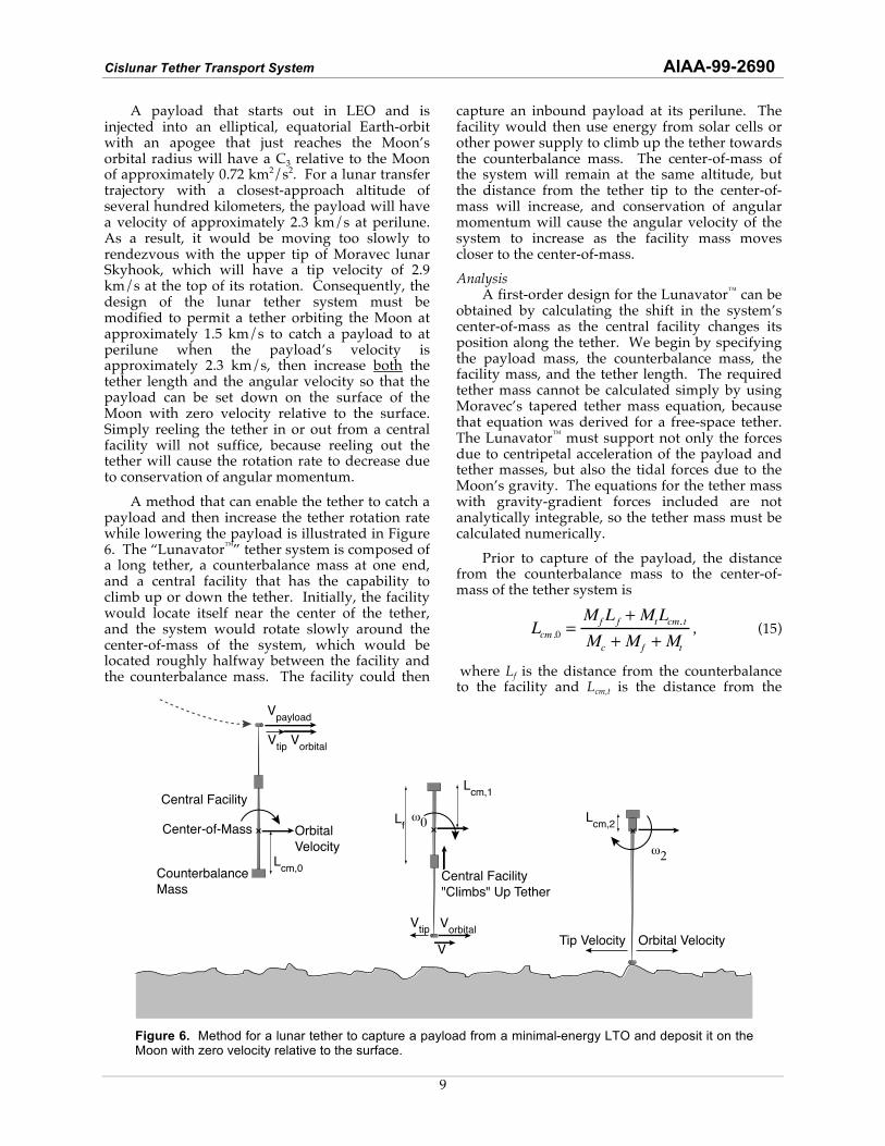
A payload that starts out in LEO and is injected into an elliptical, equatorial Earth-orbit with an apogee that just reaches the Moon’s orbital radius will have a C3 relative to the Moon of approximately 0.72 km2/s2. For a lunar transfer trajectory with a closest-approach altitude of several hundred kilometers, the payload will have a velocity of approximately 2.3 km/s at perilune. As a result, it would be moving too slowly to rendezvous with the upper tip of Moravec lunar Skyhook, which will have a tip velocity of 2.9 km/s at the top of its rotation. Consequently, the design of the lunar tether system must be modified to permit a tether orbiting the Moon at approximately 1.5 km/s to catch a payload to at perilune when the payload’s velocity is approximately 2.3 km/s, then increase both the tether length and the angular velocity so that the payload can be set down on the surface of the Moon with zero velocity relative to the surface. Simply reeling the tether in or out from a central facility will not suffice, because reeling out the tether will cause the rotation rate to decrease due to conservation of angular momentum.
A method that can enable the tether to catch a payload and then increase the tether rotation rate while lowering the payload is illustrated in Figure 6. The “Lunavator™” tether system is composed of a long tether, a counterbalance mass at one end, and a central facility that has the capability to climb up or down the tether. Initially, the facility would locate itself near the center of the tether, and the system would rotate slowly around the center-of-mass of the system, which would be located roughly halfway between the facility and the counterbalance mass. The facility could then
capture an inbound payload at its perilune. The facility would then use energy from solar cells or other power supply to climb up the tether towards the counterbalance mass. The center-of-mass of the system will remain at the same altitude, but the distance from the tether tip to the center-of-mass will increase, and conservation of angular momentum will cause the angular velocity of the system to increase as the facility mass moves closer to the center-of-mass.
Analysis A first-order design for the Lunavator™ can be obtained by calculating the shift in the system’s center-of-mass as the central facility changes its position along the tether. We begin by specifying the payload mass, the counterbalance mass, the facility mass, and the tether length. The required tether mass cannot be calculated simply by using Moravec’s tapered tether mass equation, because that equation was derived for a free-space tether. The Lunavator™ must support not only the forces due to centripetal acceleration of the payload and tether masses, but also the tidal forces due to the Moon’s gravity. The equations for the tether mass with gravity-gradient forces included are not analytically integrable, so the tether mass must be calculated numerically.
Prior to capture of the payload, the distance from the counterbalance mass to the center-of-mass of the tether system is
Lcm ,0 =Mf L f + MtLcm, t
Mc + Mf + Mt
, (15)
where Lf is the distance from the counterbalance to the facility and Lcm,t is the distance from the
Counterbalance
Mass
Central Facility
Vpayload
Center-of-Mass Orbital
Velocity
Central Facility
"Climbs" Up Tether
Tip Velocity Orbital Velocity
Vtip
Vorbital
Vtip
Vorbital
V
Lcm,0
Lcm,1
Lcm,2
!!
!"L
f
Figure 6. Method for a lunar tether to capture a payload from a minimal-energy LTO and deposit it on the Moon with zero velocity relative to the surface.

Cislunar Tether Transport System AIAA-99-2690
10
counterbalance to the center-of-mass of the tether. Lcm,t must be calculated numerically for a tapered tether.
If the Lunavator™ is initially in a circular orbit with radius a0, it will have a center-of-mass velocity of
vcm ,0
=µm
a0
. (16)
At the top of the tether swing, it can capture a payload from a perilune radius of
rp = a0 + (Lt ! Lcm ,0 ) . (17)
A payload sent from Earth on a near-minimum energy transfer will have a C3,m of approximately 0.72 km2/s2. Its perilune velocity will thus be
vp =2µm
a0+ (Lt ! Lcm ,0 )
+ C3,m
. (18)
In order for the tether tip’s total velocity to match the payload velocity at rendezvous, the velocity of the tether tip relative to the center of mass must be
vt ,0 = vp ! vcm,0 , (19)
and the angular velocity of the tether system will be
!t,0=
vt,0
Lt" L
cm, 0
. (20)
When the tether captures the payload, the center of mass of the new system, including the payload, is at perigee of a new, slightly elliptical orbit, as illustrated in Figure 7 (it was in a circular orbit and caught a payload going faster than the center-of-mass). The perigee radius and velocity of the center–of-mass are
vp,1 =vcm,0 (Mc + Mf + Mt) + vpMp
Mc +M f + Mt + Mp
, (21)
rp,1 =a0(Mc +Mf +Mt ) + rpMp
Mc + Mf + Mt + Mp
, (22)
and the new distance from the counterbalance mass to the system’s center-of-mass of the system changes to
Lcm ,1 =Mf Lf + MtLcm, t + MpLt
Mc +M f + Mt + Mp
. (23)
To increase the rotation rate of the tether system and increase the distance from the system’s center of mass to the tether tip, the
facility climbs up the tether to the counterbalance mass, reducing the distance from the counterbalance to the center-of-mass to
Lcm ,2 =MtLcm ,t + MpLt
Mc + Mf + Mt +Mp
. (24)
By conservation of angular momentum, the angular velocity will increase to a new value of
!2
= !0
Lcm ,1Mc + (Lf " Lcm ,1
)Mf +
(Lcm ,t " Lcm,1)Mt + (Lt " Lcm ,1
)Mp
#
$ %
&
' (
Lcm,2Mf + (Lcm,t " Lcm ,2
)Mt
+ (Lt " Lcm,2)Mp
#
$ %
&
' (
(25)
and the payload will then have a velocity relative to the center-of-mass of
vt ,2
=!2(L
t" L
cm ,2) . (26)
If the initial orbit parameters, tether lengths, and facility and tether masses are chosen properly, then vt,2 can be made equal to the perigee velocity of the tether system and the distance from the center of mass to the payload can be made equal to the perigee altitude. When the tether returns to its perigee it can then deposit the payload on the surface of the Moon and simultaneously pick up a payload to be thrown back to Earth.
Lunavator™ Design Using the equations given above, we have found the following first-order design for a Lunavator™ capable of catching payloads from minimal-energy lunar transfer orbits and depositing them on the surface of the Moon:
Payload Trajectory: • mass Mp = 2500 kg • perigee altitude hp = 328.23 km • Moon-relative energy C3,M = 0.719 km2/s2
Lunavator™:
Payload
from
Earth
Orbit prior
to catch
Orbit after
catch
Figure 7. Lunavator™ orbits before and after payload capture.

Cislunar Tether Transport System AIAA-99-2690
11
• tether length L = 200 km • counterbalance mass Mc = 15,000 kg • facility mass Mf = 15,000 kg • tether mass Mt = 11,765 kg • Total Mass M = 41,765 kg = 16.7 x payload mass • Orbit Before Catch:
central facility position Lf = 155 km tether tip velocity Vt,0 = 0.748 km/s rotation rate #0 = 0.00566 rad/s circular orbit altitude hp,0 = 170.5 km
• Orbit After Catch: perigee altitude hp,0 = 178 km, apogee altitude ha,0 = 411.8 km eccentricity e0 = 0.0575
After catching the payload, the central facility climbs up the tether to the counterbalance mass, changing the rotation rate to: • adjusted rotation rate #0 = 0.00929rad/s • adjusted tip velocity Vt,2 = 1.645 km/s
Payload Delivery: • drop-off altitude h = 1 km (top of a lunar mountain) • velocity w.r.t. surface v = 0 m/s
Lunavator™ Orbit: Polar vs. Equatorial In order to provide the most consistent transfer scenarios, it is desirable to place the Lunavator™ into either a polar or equatorial lunar orbit. Each choice has relative advantages and drawbacks, but both are viable options.
Equatorial Lunar Orbit The primary advantage of an equatorial orbit for the Lunavator™ is that equatorial lunar orbits are relatively stable. An equatorial Lunavator™, however, would only be able to service traffic to bases on the lunar equator. Because the lunar equatorial plane is tilted with respect to the Earth’s equatorial plane, a payload boosted by the Earth-orbit tether facility will require a !V maneuver to bend its trajectory into the lunar equatorial plane. This !V can be provided either using a small rocket thrust or a lunar “slingshot”
maneuver. These options will be discussed in more detail in a following section.
Polar Lunar Orbit A polar orbit would be preferable for the Lunavator™ for several reasons. First, direct transfers to polar lunar trajectories are possible with little or no propellant expenditure required. Second, because a polar lunar orbit will remain oriented in the same direction while the Moon rotates inside of it, a polar Lunavator™ could service traffic to any point on the surface of the Moon, including the potentially ice-rich lunar poles. Polar lunar orbits, however, are unstable. The odd-harmonics of the Moon’s potential cause a circular, low polar orbit to become eccentric, as illustrated in Figure 8. Eventually, the eccentricity becomes large enough that the perilune is at or below the lunar surface. For the 178 km circular orbit, the rate of eccentricity growth is approximately 0.00088 per day.
Fortunately, the techniques of orbital modification using tether reeling, proposed by Martínez-Sánchez and Gavit7 and by Landis9 may provide a means of stabilizing the orbit of the Lunavator™ without requiring expenditure of propellant. Tether reeling can add or remove energy from a tether’s orbit by working against the non-linearity of a gravitational field. The basic concept of orbital modification using tether reeling is illustrated in Figure 9. When a tether is near the apoapsis of its orbit, the tidal forces on the tether are low. When it is near periapsis, the tidal forces on the tether are high. If it is desired to reduce the eccentricity of the tether’s orbit, then the tether can
2001501005000.00
0.05
0.10
0.15
0.20
Time(days)
eccentricity
Figure 8. Evolution of the eccentricity of an initially circular 178 km polar lunar orbit, without tether reeling.
Reel tether in
against low tidal force
Extend tether under
high tidal force
Figure 9. Schematic of tether reeling maneuver to reduce orbital eccentricity.

Cislunar Tether Transport System AIAA-99-2690
12
be reeled in when it is near apoapsis, under low tension, and then allowed to unreel under higher tension when it is at periapsis. Since the tidal forces that cause the tether tension are, to first order, proportional to the inverse radial distance cubed, more energy is dissipated as the tether is unreeled at periapsis than is restored to the tether’s orbit when it is reeled back in at apoapsis. Thus, energy is removed from the orbit. Conversely, energy can be added to the orbit by reeling in at periapsis and reeling out at apoapsis. Although energy is removed (or added) to the orbit by the reeling maneuvers, the orbital angular momentum of the orbit does not change. Thus the eccentricity of the orbit can be changed.
The theories developed in references 7 and 9 assumed that the tether is hanging (rotating once per orbit). Because the Lunavator™ will be rotating several times per orbit, we have extended the theory to apply to rapidly rotating tethers.8 Using a tether reeling scheme in which the tether is reeled in and out once per orbit as shown in Figure 9, we find that a reeling rate of 1 m/s will reduce the eccentricity of the Lunavator™’s orbit by 0.0011 per day, which should be more than enough to counteract the effects of lunar perturbations to the tether’s orbit. Thus tether reeling may provide a means of stabilizing the orbit of a polar Lunavator™ without requiring propellant expenditure. This tether reeling, however, would add additional complexity to the system.
Cislunar System Simulations Tether System Modeling In order to verify the design of the orbital dynamics of the Cislunar Tether Transport System, we have developed a numerical simulation called “TetherSim” that includes:
• The 3D orbital mechanics of the tethers and
payloads in the Earth-Moon system, including the effects of Earth oblateness, using Runge-Kutta integration of Cowell’s method.
• Modeling of the dynamical behavior of the tethers, using a bead-and-spring model similar to that developed by Kim and Vadali.10
• Modeling of the electrodynamic interaction of the Earth-orbit tether with the ionosphere.
Using this simulation tool, we have developed a scenario for transferring a payload from a circular low-LEO orbit to the surface of the Moon using the tether system designs outlined above. We have found that for an average transfer scenario, mid-course trajectory corrections of approximately 25 m/s are necessary to target the payload into the desired polar lunar trajectory to enable rendezvous with the Lunavator™. A simulation of a transfer from LEO to the surface of the Moon can be viewed at www.tethers.com.
Targeting the Lunar Transfer In addition to the modeling conducted with TetherSim, we have also conducted a study of the Earth-Moon transfer to verify that the payload can be targeted to arrive at the Moon in the proper plane to rendezvous with the Lunavator™. This study was performed with the MAESTRO code,11 which includes the effects of luni-solar perturbations as well as the oblateness of the Earth. In this work we studied targeting to both equatorial and polar lunar trajectories.
Transfer to Equatorial Lunar Trajectories Transfer of a payload from an equatorial Earth trajectory to an equatorial lunar trajectory can be achieved without propellant expenditure, but this requires use of a one-month “resonance hop” transfer, as illustrated in Figure 10. In a resonance hop maneuver, the payload is sent on a trajectory that passes the Moon in such a way that the lunar gravitational field slingshots the payload’s orbit into a one-month Earth orbit that returns to the Moon in the lunar equatorial plane. Using MAESTRO, we have developed a lunar transfer scenario that achieves this maneuver.
In order to avoid the one-month transfer time, we can instead use a small impulsive thrust as the payload crosses the lunar equator to bend its trajectory into the equatorial plane. A patched-conic analysis of such a transfer predicts that such a maneuver would require 98 to 135 m/s of !V. However, our numerical simulations of the transfer revealed that under most conditions, luni-solar perturbations of the payload’s trajectory will perform much of the needed bending for us, and the velocity impulse needed to place the payload
Earth
Equatorial Plane
Lunar Orbit
Inclined 18.3° - 28.6°
to Earth Equator
One-Month Lunar Return Orbit
In Lunar Equator
Note: Apogee > Lunar Orbit
Perigee < Lunar Orbit
Lunar Transfer Orbit
C3 = - 1.9 to -1.2 km2/s2
In Earth Equatorial Plane
Lunar Swingby Radius
5000 to 10000 km
Figure 10. Schematic of one-month “resonance-hop” transfer to place payload in lunar equator without using propellant.

Cislunar Tether Transport System AIAA-99-2690
13
in a lunar equatorial trajectory is only about 25 m/s. Figure 11 shows the time-history of a transfer of a payload from the Earth-orbit tether boost facility to the Moon, projected onto the Earth’s equatorial plane.
Figure 12 shows this same transfer, projected onto the lunar equatorial plane in a Moon centered, rotating frame, with the x-axis pointing at the Earth. The motion of the payload relative to the lunar equator can be observed in Figure 13, which shows the trajectory projected onto the lunar x-z plane. The payload crosses the lunar equator approximately 10 hours before its closest approach to the Moon. Figure 14, which plots the Moon-relative velocity of the payload, shows that the payload’s velocity at the time of lunar equatorial crossing is about 925 m/s. However, a plot of the declination of the payload’s velocity with respect to the lunar equator, shown in Figure 15, reveals that that the declination of the Moon-relative velocity vector is only a few degrees, much less than the 18°-29° value predicted by a simple zero-patched conic analysis; the Moon's (or Sun's) gravity has bent the velocity vector closer to the lunar orbit plane.
At the time when the payload’s trajectory crosses the lunar equator, the declination of the incoming velocity vector is only 1.52°. This dynamical situation permits us to bend the approach trajectory into the lunar equator with a very small amount of impulse supplied by the spacecraft propulsion system. In the case shown
here, the amount of %V required is only 24.5 m/s, applied about 10 hours before closest approach to the Moon, as the spacecraft crosses the lunar equator.
Transfer to Polar Lunar Trajectories Figure 16 shows a payload transfer targeted to a polar lunar trajectory with an ascending node (with respect to the lunar prime meridian) of –100.95°. This particular trajectory is a Type II transfer, with a central angle on the initial orbit of greater than 180°. Similar transfers can be achieved with Type I trajectories (central angle of less than 180°). Essentially, these transfers are achieved by injecting the payload into an orbit that just reaches the Moon’s orbit near the point where the Moon will cross the Earth’s equatorial plane. When the payload reaches its apogee, it is moving only a few hundred meters per second. As the payload slowly drifts towards its apogee, the Moon approaches, moving at just over 1 km/s. The Moon then “captures” the payload, pulling it into a trajectory that is just barely hyperbolic relative to the Moon.
1000000-100000-200000-300000-400000-80000
-60000
-40000
-20000
0
20000
40000
x(km)
y(k
m)
Launch from Earth
Closest Approach to Moon
Figure 11. Transfer of payload to lunar equatorial trajectory, projected onto the True Earth Equator.
4000003000002000001000000-100000-200000
-100000
0
100000
x(km)
y(k
m)
Launch from EarthLunar Closest Approach
Figure 12. Projection of payload transfer onto Lunar Equatorial Plane (Moon centered frame).
4000003000002000001000000-100000-10000
-8000
-6000
-4000
-2000
0
2000
4000
x(km)
z(k
m)
Launch from Earth
Closest Approach to Moon
Payload Crosses
Lunar Equator
Figure 13. Projection of payload transfer onto Lunar x-z plane (Moon centered frame).
1501005000.0
0.5
1.0
1.5
2.0
Time (hrs)
V(k
m/s
)
Spacecraft Crosses Lunar Equator (V = 0.925 km/s)
Figure 14. Moon-relative velocity of spacecraft.
1501005000.0
0.5
1.0
1.5
2.0
2.5
3.0
3.5
4.0
4.5
5.0
Time (hrs)
DecV
(deg)
Spacecraft Crosses Lunar Equator (Declination of Velocity = 1°.52)
Figure 15. Declination of Moon-relative velocity vector with respect to Lunar Equator.

Cislunar Tether Transport System AIAA-99-2690
14
We have found that by varying the energy of the translunar trajectory and adjusting the argument of perigee, it is possible to target the payload to rendezvous with a polar orbit Lunavator™ with a wide range of ascending node positions of the Lunavator™ orbit. Our simulations indicate that the viable nodal positions ranges at least ±10° from the normal to the Earth-Moon line.
Comparison to Rocket Transport Travelling from LEO to the surface of the Moon and back requires a total !V of more than 10 km/s. To perform this mission using storable chemical rockets, which have an exhaust velocity of roughly 3.5 km/s, the standard rocket equation requires that a rocket system consume a propellant mass equal to 16 times the mass of the payload for each mission. The Cislunar Tether Transport System would require an on-orbit mass of less than 28 times the payload mass, but it would be able to transport many payloads. In practice, the tether system will require some propellant for trajectory corrections and rendezvous maneuvers, but the total !V for these maneuvers will likely be less than 100 m/s. Thus a simple comparison of rocket propellant mass to tether system mass indicates that the fully reusable tether transport system could provide significant launch mass savings after only a few round trips. Although the development and deployment costs associated with a tether system would present a larger up-front expense than a rocket based system, for frequent, high-volume round trip traffic to the Moon, a tether system could achieve large reductions in transportation costs by eliminating the need to launch large quantities of propellant into Earth orbit.
Summary Our analyses have concluded that the optimum architecture for a tether system designed to transfer payloads between LEO and the lunar surface will utilize one tether facility in an elliptical, equatorial Earth orbit and one tether in low lunar orbit. We have developed a preliminary design for a 80 km long Earth-orbit tether boost facility capable of picking payloads up from LEO and injecting them into a minimal-energy lunar transfer orbit. Using currently available tether materials, this facility would require a mass 10.5 times the mass of the payloads it can handle. After boosting a payload, the facility can use electrodynamic propulsion to reboost its orbit, enabling the system to repeatedly send payloads to the Moon without requiring propellant or return traffic. When the payload reaches the Moon, it will be caught and transferred to the
surface by a 200 km long lunar tether. This tether facility will have the capability to reposition a significant portion of its “ballast” mass along the length of the tether, enabling it to catch the payload from a low-energy transfer trajectory and then “spin-up” so that it can deliver the payload to the Moon with zero velocity relative to the surface. This lunar tether facility would require a total mass of less than 17 times the payload mass. Both equatorial and polar lunar orbits are feasible for the Lunavator™. Using two different numerical simulations, we have tested the feasibility of this design and developed scenarios for transferring payloads from a low-LEO orbit to the surface of
the Moon, with only 25 m/s of !V needed for small trajectory corrections. Thus, it appears feasible to construct a Cislunar Tether Transport System with a total on-orbit mass requirement of less than 28 times the mass of the payloads it can handle, and this system could greatly reduce the cost of round-trip travel between LEO and the surface of the Moon by minimizing the need for propellant expenditure.
Acknowledgments This research was supported by a Phase I grant from NASA’s Institute for Advanced Concepts, contract number NIAC-07600-011. Earlier work on this concept was supported by a subcontract on the NASA Grant NAG8-1303 to the Smithsonian Astrophysical Observatory. The authors would like to acknowledge Robert L. Forward of Tethers Unlimited, Inc., Enrico Lorenzini of SAO, and Joe Carroll of Tether Applications for helpful discussions.
References 1. Forward, R. L., “Tether Transport from LEO to the
Lunar Surface,” AIAA paper 91-2322, July 1991.
2. Hoyt, R. P., Forward, R. L., “Tether System for Exchanging Payloads Between Low Earth Orbit and the Lunar Surface”, AIAA 97-2794, July 1997.
3. Danby, J.M.A., Fundamentals of Celestial Mechanics, 2nd Edition, Willmann-Bell, 1992, Ch. 14.
1000000-100000-200000-300000-400000-100000
-80000
-60000
-40000
-20000
0
20000
40000
y(km)
Earth Equatorial x (km)
Eart
h E
qu
ato
rial y (
km
)
Initial Argument of Perigee = 11°.93
Lunar Closest Approach
One-Hour Time Ticks
Figure 16. Time history of an Earth-Moon transfer targeted to a polar lunar trajectory.

Cislunar Tether Transport System AIAA-99-2690
15
4. Moravec, H., “A Non-Synchronous Orbital Skyhook,” Journal of the Astronautical Sciences., 25(4), Oct-Dec1977, pp. 307-322.
5. Battin, R. H., An Introduction to the Mathematics and Methods of Astrodynamics, AIAA, 1987, p. 504.
6. Failure Resistant Multiline Tether, Robert L. Forward and Robert P. Hoyt, PCT/US97/05840, filed 22 April 1997.
7. Martínez-Sánchez, M., Gavit, S.A., “Orbital Modifications using Forced Tether Length Variations”, Journal of Guidance, Control, and Dynamics, 10(3) May-June 1987, pp 233-241.
8. Hoyt, R. P., “Maintenance Of Rotating Tether Orbits Using Tether Reeling”, Appendix F in Cislunar Tether Transport System, Tethers Unlimited, Inc. Final Report on NASA Institute for Advanced Concepts Contract NIAC-07600-011.
9. Landis, G.A., “Reactionless Orbital Propulsion using Tether Deployment,” Acta Astronautica 26(5), IAF Paper 90-254, 1992.
10. Kim, E., Vadali, S.R. “Modeling Issues related to Retrieval of Flexible Tethered Satellite Systems,” Journal of Guidance, Control, and Dynamics, 18(5), 1995, pp 1169-76.
11. Uphoff, C., “Mission Analysis Evaluation and Space Trajectory Optimization Program”, Final Report on NASA Contract NAS5-11900, March 1973.