citiled cob horticulture series
TRANSCRIPT
1 Ref_CE-0673P-202009
DATA SHEET
Introduction
Performance Characteristics
Mechanical Dimensions
Characteristic Curves
Reliability
Packing Specification
Precaution
P 2
P 3
P 4
P 5
P 8
P 9
P 10
CITILED COB
Horticulture series
CLU03H-25/55-PW -01
Ref_CE-0673P-202009
1. Introduction
1-1. Product Description
1-2. Features
2
CLU03 H - 25 / 55 - PW - 01[1] [2] [3] [4] [5]
[1]
[2]
[3]
[4]
[5]
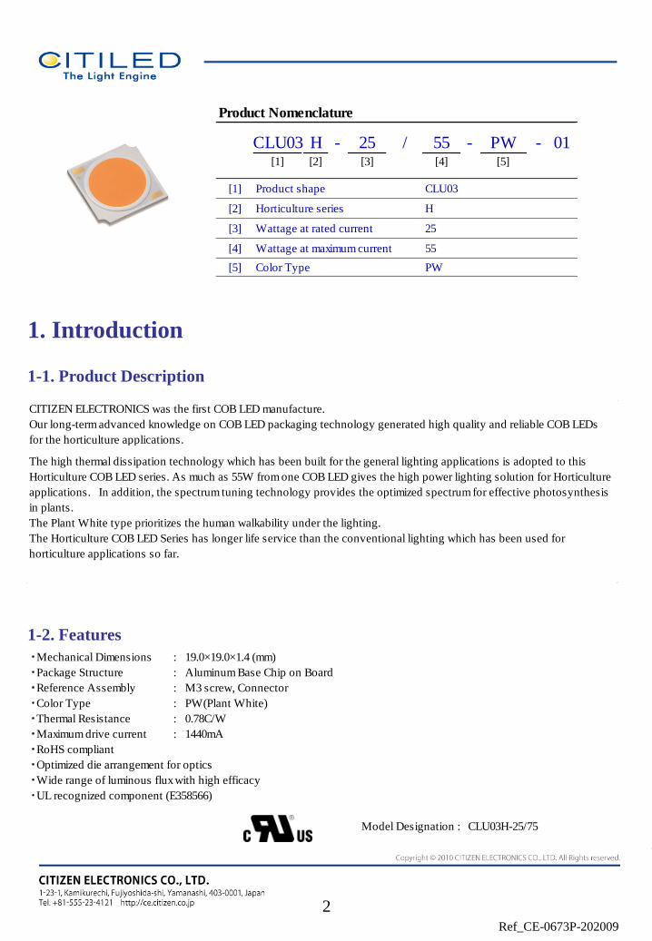
Wattage at rated current
Wattage at maximum current
Color Type
Product Nomenclature
Product shape
Horticulture series
CLU03
H
25
55
PW
CITIZEN ELECTRONICS was the first COB LED manufacture.
Our long-term advanced knowledge on COB LED packaging technology generated high quality and reliable COB LEDs
for the horticulture applications.
The high thermal dissipation technology which has been built for the general lighting applications is adopted to this
Horticulture COB LED series. As much as 55W from one COB LED gives the high power lighting solution for Horticulture
applications. In addition, the spectrum tuning technology provides the optimized spectrum for effective photosynthesis
in plants.
The Plant White type prioritizes the human walkability under the lighting.
The Horticulture COB LED Series has longer life service than the conventional lighting which has been used for
horticulture applications so far.
・Mechanical Dimensions : 19.0×19.0×1.4 (mm)
・Package Structure : Aluminum Base Chip on Board
・Reference Assembly : M3 screw, Connector
・Color Type : PW(Plant White)
・Thermal Resistance : 0.78C/W
・Maximum drive current : 1440mA
Model Designation : CLU03H-25/75
・RoHS compliant
・Optimized die arrangement for optics
・Wide range of luminous flux with high efficacy
・UL recognized component (E358566)
Ref_CE-0673P-202009
2. Performance Characteristics
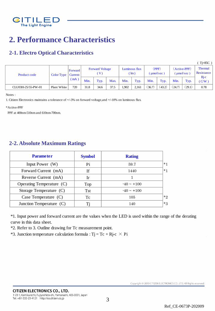
2-1. Electro Optical Characteristics
2-2. Absolute Maximum Ratings
3
Symbol Rating
Pi 59.7 *1
If 1440 *1
Ir 1
Top -40 ~ +100
Tst -40 ~ +100
Tc 105 *2
Tj 140 *3
*3. Junction temperature calculation formula : Tj = Tc + Rj-c × Pi
Storage Temperature (C)
Case Temperature (C)
Junction Temperature (C)
Operating Temperature (C)
*1. Input power and forward current are the values when the LED is used within the range of the derating
curve in this data sheet.
*2. Refer to 3. Outline drawing for Tc measurement point.
Parameter
Input Power (W)
Forward Current (mA)
Reverse Current (mA)
( Tj=85C )
Min. Typ. Max. Min. Typ. Min. Typ. Min. Typ.
CLU03H-25/55-PW-01 Plant White 720 31.8 34.6 37.5 1,902 2,161 (36.7)(43.2)(24.7)(29.1) 0.78
Notes :
1. Citizen Electronics maintains a tolerance of +/-3% on forward voltage,and +/-10% on luminous flux.
*Active-PPF
PPF at 400nm-510nm and 610nm-700nm.
Forward Voltage
( V )
Luminous flux
( lm )
(Active-PPF)
( μmol/sec )
Thermal
Resistance
Rj-c
( C/W )
(PPF)
( μmol/sec )Product code
Forward
Current
( mA )
Color Type
Ref_CE-0673P-202009
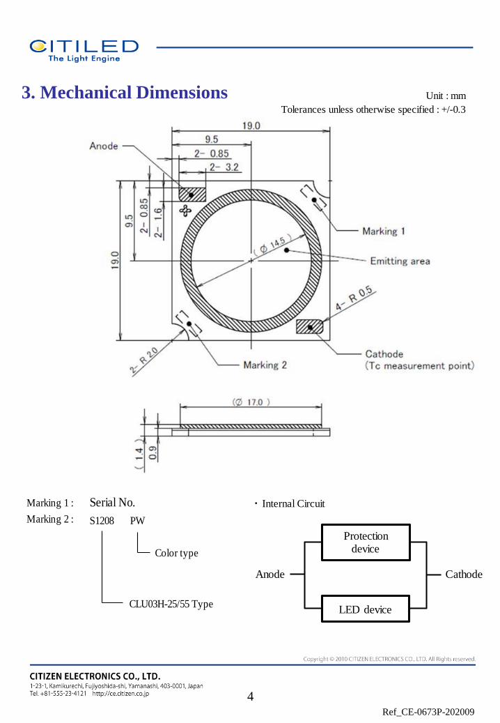
3. Mechanical Dimensions
4
Unit : mm
Tolerances unless otherwise specified : +/-0.3
・Internal Circuit
Protection device
LED device
CathodeAnode
Marking 1 : Serial No.
Marking 2 :
Color type
CLU03H-25/55 Type
S1208 PW
Ref_CE-0673P-202009
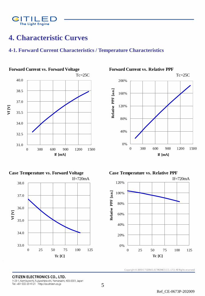
4. Characteristic Curves
4-1. Forward Current Characteristics / Temperature Characteristics
5
Forward Current vs. Forward Voltage Forward Current vs. Relative PPF
Tc=25C Tc=25C
Case Temperature vs. Forward Voltage Case Temperature vs. Relative PPF
If=720mA If=720mA
33.0
34.0
35.0
36.0
37.0
38.0
0 25 50 75 100 125
Vf
[V]
Tc [C]
0%
40%
80%
120%
160%
200%
0 300 600 900 1200 1500
Rela
tive
P
PF
[a.u
.]
If [mA]
0%
20%
40%
60%
80%
100%
120%
0 25 50 75 100 125
Rela
tive
P
PF
[a.u
.]
Tc [C]
31.0
32.5
34.0
35.5
37.0
38.5
40.0
0 300 600 900 1200 1500
Vf
[V]
If [mA]
Ref_CE-0673P-202009
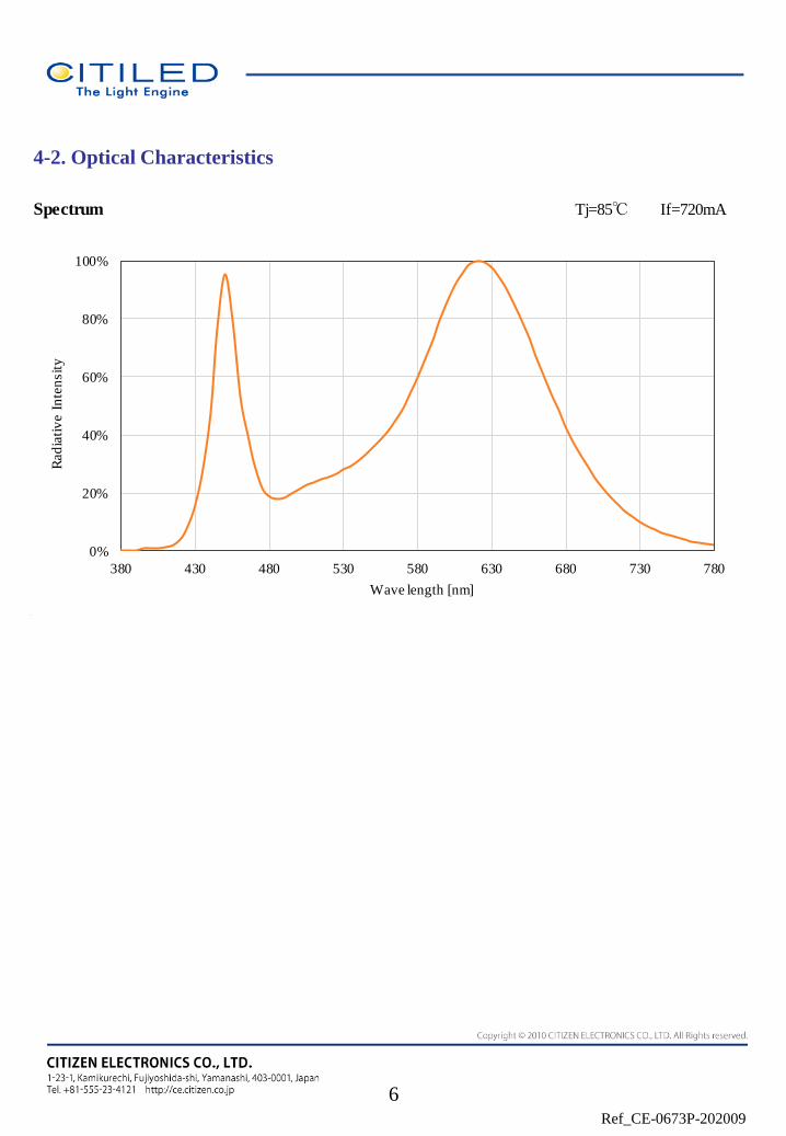
Spectrum Tj=85℃ If=720mA
0%
20%
40%
60%
80%
100%
380 430 480 530 580 630 680 730 780
Rad
iati
ve I
nte
nsit
y
Wave length [nm]
4-2. Optical Characteristics
6
Ref_CE-0673P-202009
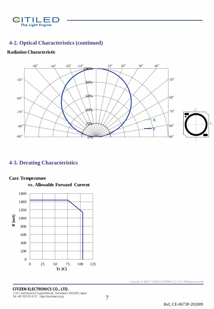
4-2. Optical Characteristics (continued)
4-3. Derating Characteristics
Radiation Characteristic
0%
20%
40%
60%
80%
100%
X
Y80°
70°
60°
50°
40°30°20°10°
-80°
-70°
-60°
-50°
-20°-30°-40° -10°
90°-90°
7
0
200
400
600
800
1000
1200
1400
1600
0 25 50 75 100 125
If [
mA
]
Tc [C]
Case Temperature
vs. Allowable Forward Current
0
200
400
600
800
1000
1200
1400
1600
0 25 50 75 100 125
If [
mA
]
Tc [C]
Ref_CE-0673P-202009
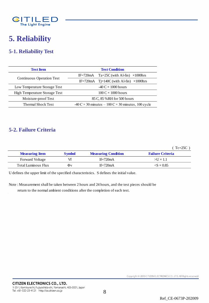
5. Reliability
5-1. Reliability Test
5-2. Failure Criteria
Test Item
100 C × 1000 hours
-40 C × 1000 hours
Test Condition
IF=720mA Ta=25C (with Al-fin) ×1000hrs
-40 C × 30 minutes – 100 C × 30 minutes, 100 cycle
85 C, 85 %RH for 500 hours
Thermal Shock Test
Continuous Operation Test
High Temperature Storage Test
Low Temperature Storage Test
Moisture-proof Test
IF=720mA Tj=140C (with Al-fin) ×1000hrs
8
( Tc=25C )
U defines the upper limit of the specified characteristics. S defines the initial value.
Note : Measurement shall be taken between 2 hours and 24 hours, and the test pieces should be
return to the normal ambient conditions after the completion of each test.
Total Luminous Flux Φv If=720mA <S × 0.85
Measuring Item Symbol Measuring Condition Failure Criteria
Forward Voltage Vf If=720mA >U × 1.1
Ref_CE-0673P-202009
2 0 9 5 0 0 1
(2)
5. Model Designation
4. Quantity
(1) Last two digit of the year 20 : Year 2020
(2) Production month 9 : September
Note: October, November and December are designated X,Y and Z.
(3) CE's control number
(1) (3)
Example of indication label
1. TYPE e.g. CLU03H-25/55-PW-01
2. P.No. ( Customer's P/N )
3. Lot No.
e.g.
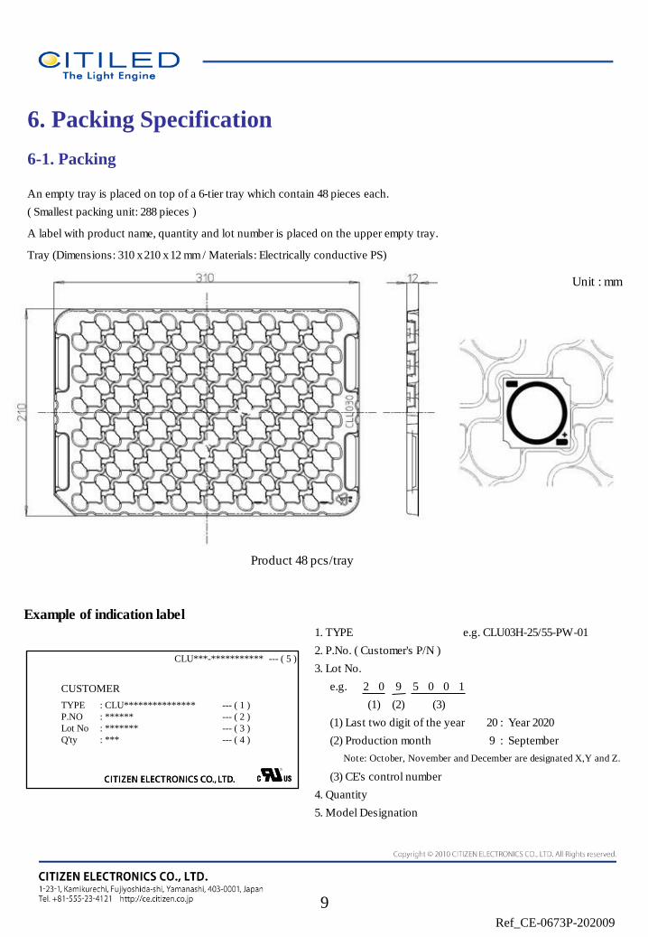
6. Packing Specification
6-1. Packing
9
An empty tray is placed on top of a 6-tier tray which contain 48 pieces each.
( Smallest packing unit: 288 pieces )
A label with product name, quantity and lot number is placed on the upper empty tray.
Tray (Dimensions: 310 x 210 x 12 mm / Materials: Electrically conductive PS)
Unit : mm
Product 48 pcs/tray
CUSTOMER
TYPE
P.NO
Lot No
Q'ty
: CLU***************
: ******
: *******
: ***
--- ( 1 )
--- ( 2 )
--- ( 3 )
--- ( 4 )
CLU***-*********** --- ( 5 )
Ref_CE-0673P-202009
7. Precaution
7-1. Handling with care for this product - Both the light emitting area and white rim around the light emitting area is composed of resin materials.
Please avoid the resin area from being pressed, stressed, rubbed, come into contact with sharp metal nail
(e.g. edge of reflector part) because the function, performance and reliability of this product are negatively impacted.
- Please be aware that this product should not come into contact with any other parts while incorporating in your lighting
apparatus or your other products. - Please be aware that careful handling is required after the attachment of lead wires to prevent the application of any load to the connections. - For more information, please refer to application note "Instruction Manual(COB LED Package)".
7-2. Countermeasure against static electricity
- Handling of this product needs countermeasures against static electricity because this is a semiconductor product.
- Please take adequate measures to prevent any static electricity being produced such as the wearing of a wristband or
anti-static gloves when handling this product.
- Every manufacturing facility in regard to the product (plant, equipment, machine, carrier machine and conveyance unit)
should be connected to ground and please avoid the product to be electric-charged.
- ESD sensitivity of this product is over 1000V (HBM, based on JEITA ED-4701/304).
- After assembling the LEDs into your final product(s), it is recommended to check whether the assembled LEDs are
damaged by static electricity (electrical leak phenomenon) or not. - It is easy to find static damaged LED dies by a light-on test with the minimum current value.
7-3. Caution of product assembly
- Regarding this product assembling on the heat sink, it is recommended to use M3 screw.
It might be good for screw tightening on the heat sink to do temporary tightening and final tightening.
In addition, please don’t press with excess stress on the product.
- The conditions of this product assembling to the heat sink and the control of screw tightening torque needs to
be optimized according to the specification of the heat sink.
- Roughness, unevenness and burr of surface negatively impact thermal bonding between the product and heat sink and
increase heat thermal resistance between them.
Confidence of thermally and mechanical coupling between the product and heat sink are confirmed by checking
the mounting surface or measuring the case temperature of the product.
- In order to reduce the thermal resistance during assembly, it might be good to use TIM (Thermal Interface Material) on
whole contact surface of the product.
In case of using thermal grease type for the TIM, it might be good to apply uniformly
on the contact surface of the product. In case of using thermal sheet type for the TIM,
it might be good to make sure that the product is NOT strained by stress when the screws are tightened for assembly.
- For further information, please refer to application note "Instruction Manual(COB LED Package)".
10
Ref_CE-0673P-202009
7-4. Thermal Design
- The thermal design to draw heat away from the LED junction is most critical parameter for an LED illumination system.
High operating temperatures at the LED junction adversely affect the performance of LED’s light output and lifetime.
Therefore the LED junction temperature should not exceed the absolute maximum rating in LED illumination system.
- The LED junction temperature while operation of LED illumination system depends upon thermal resistance of internal
LED package (Rj-c), outer thermal resistances of LED package, power loss and ambient temperature. Please take both of
the thermal design specifications and ambient temperature conditions into consideration for the setting of driving
conditions. - For more information, please refer to application note "Thermal Management", "Instruction Manual(COB LED Package)".
7-5. Driving Current
- A constant current is recommended as an applying driving current to this product.
In the case of constant voltage driving, please connect current-limiting resistor to each LED row in series and control
the driving current to keep under the absolute maximum rating forward current value.
- Electrical transient might apply excess voltage, excess current and reverse voltage to the product(s).
They also affect negative impact on the product(s) therefore please make sure that no excess voltage, no excess current
no reverse voltage is applied to the product(s) when the LED driver turn-on and/or turn-off. - For more information, please refer to application note "Driving", "Instruction Manual(COB LED Package)".
7-6. Lighting at a minimum current value
7-7. Electrical Safety
- This product is designed and produced according to IEC 62031:2008
(IEC 62031:2008 LED modules for general lighting. Safety specification)
- Dielectric voltage withstand test has been conducted on this product to see any failure after applying
voltage between active pads and aluminum section of the product, and to pass at least 500V.
- Considering conformity assessment for IEC62031:2008, almost all items of the specification depend upon
your final product of LED illumination system.
Therefore, please confirm with your final product for electrical safety of your product.
As well, the products comply with the criteria of IEC62031:2008 as single LED package.
11
-A minimum current value of lighting of all dice is 40mA
When a minimum current is applied, LED dice may look different in their brightness due to
the individual difference of the LED element, and it is not a failed product.
Ref_CE-0673P-202009
7-8. Recommended soldering Condition (This product is not adaptable to reflow process.)
- For manual soldering
Please use lead-free soldering.
Soldering shall be implemented using a soldering bit at a temperature lower than 350C, and shall be
finished within 3.5 seconds for one land.
No external force shall be applied to resin part while soldering is implemented.
Next process of soldering should be carried out after the product has return to ambient temperature.
Contacts number of soldering bit should be within twice for each terminal.
* Citizen Electronics cannot guarantee if usage exceeds these recommended conditions. Please use it after sufficient verification is carried out on your own risk if absolutely necessary. -For more information, please refer to application note " Instruction Manual (COB LED Package) ".
7-9. This product is not designed for usage under the following conditions.
- If the product might be used under the following conditions, you shall evaluate its effect and appropriate them.
In places where the protective actions.
- directly and indirectly get wet due to rain and/or at place with the fear. - be damage by seawater and/or at place with the fear
- be exposed to corrosive gas (such as Cl2, H2S, NH3, SOx, NOx and so on) and/or at place with the fear. - be exposed to dust, fluid or oil and/or at place with the fear.
12
Ref_CE-0673P-202009
13
Precautions with regard to product use
(1) This document is provided for reference purposes only so that CITIZEN ELECTRONICS' products are
used as intended. CITIZEN ELECTRONICS neither makes warranties or representations with respect to
the accuracy or completeness of the information contained in this document nor grants any license to any
intellectual property rights or any other rights of CITIZEN ELECTRONICS or any third party with
respect to the information in this document. Formal specifications must be exchanged and signed by both
parties prior to mass production.
(2) All information included in this document such as product data, diagrams, charts, is current as of the
date this document is issued.
Such information, however, is subject to change without any prior notice.
(3) CITIZEN ELECTRONICS has used reasonable care in compiling the information included in this
document, but CITIZEN ELECTRONICS assumes no liability whatsoever for any damages incurred as a
result of errors or omissions in the information included in this document.
(4) Absent a written signed agreement, except as provided in the relevant terms and conditions of sale for
product, and to the maximum extent allowable by law, CITIZEN ELECTRONICS assumes no liability
whatsoever, including without limitation, indirect, consequential, special, or incidental damages or loss,
including without limitation, loss of profits, loss of opportunities, business interruption and loss of data,
and disclaims any and all express or implied warranties and conditions related to sale, use of product, or
information, including warranties or conditions of merchantability, fitness for a particular purpose,
accuracy of information, or no infringement.
(5) Though CITIZEN ELECTRONICS works continually to improve products' quality and reliability,
products can malfunction or fail. Customers are responsible for complying with safety standards and for
providing adequate designs and safeguards to minimize risk and avoid situations in which a malfunction or
failure of a product could cause loss of human life, bodily injury or damage to property, including data loss
or corruption. In addition, customers are also responsible for determining the appropriateness of use of any
information contained in this document such as application cases not only by evaluating on their own but
also by using the entire system. CITIZEN ELECTRONICS assumes no liability for customers' product
design or applications.
(6) The product is intended to be used for general electronic equipment such as general lighting, home
appliances, and information-communication equipment. It is not designed or manufactured to be used for
special application (e.g. automobiles, trains, ships, airplanes, spaceships, submarine repeaters, atomic
energy control systems, traffic equipment, combustion equipment, life-support systems, and safety
devices). We will not guarantee any application suitability for goods like those described above that require
special quality and reliability. In cases where the product is used in special applications and it causes
extensive property damage, threatens human life or damages the human body, we will not be held liable.
The product is not in conformity to ISO/TS16949 (IATF16949) or intended to be used for in-vehicle
application.
(7) Do not reverse-engineer the product including disassemble or analyze without our approval.
(8) Please contact CITIZEN ELECTRONICS' sales office if you have any questions regarding the
information contained in this document, or if you have any other inquiries.
Ref_CE-0673P-202009
14
Precautions with regard to product use
(9) It is the sole and exclusive responsibility of the purchaser to determine and abide by all applicable local, state, federal,
national, and international laws in connection with the use of this Citizen Electronics Co., Ltd. product. By purchasing this
product, purchaser represents that the product will be used solely and exclusively for lawful purposes and those purposes
intended by the manufacturer and seller. Citizen Electronics Co., Ltd., its parent, affiliates and related companies will not
be held liable for any misuse or misapplication of the product.
Ref_CE-0673P-202009
is a trademark or a registered trademark of CITIZEN ELECTRONICS CO., LTD. JAPAN.
15