citiled cob series vivid type -...
TRANSCRIPT
1 Ref.CE-P2932 11/14
DATA SHEET
Introduction
Performance Characteristics
Mechanical Dimensions
Characteristic Curves
Reliability
Packing Specification
Precaution
P 2
P 3
P 5
P 6
P 8
P 9
P 10
CITILED COB Series
VIVID Type
CLU034-1206B8
Ref.CE-P2932 11/14
1. Introduction
1-1. Product Description
1-2. Features
CITIZEN ELECTRONICS is the first COB manufacture. Our advanced knowledge and packaging technology for many years has
excellent reliability and high quality of our products. CITILED COB Series covers a wide range of luminous flux from a 10W
incandescent bulb to a 300W mercury lamp in general lighting sources. The element arrangement of LED package is capable of utilizing
light more effectively and higher performance.
The newest version of CITILED COB Series offers the superior vivid color.
In addition to the high color rendering LEDs aimed at making the color of objects more faithful, the demands on high chromatic LEDs
targeted for making objects more vivid are increasing. These new products are the most suitable for the applications that place
emphasis on the appearance of commercial products such as for store lighting, and lighting for sign boards. Citizen Electronics has
developed high chromatic LEDs that enable the vivid appearance of objects by selecting LED dice or phosphor and vivid appearance
of objects by selecting LED dice or phosphor and tuning the light emitting spectrum.
2
・Mechanical Dimensions : 19.0 x 19.0 x 1.4 (mm)
・Package Structure : Aluminum Base Chip on Board
・Reference Assembly : M3 screw, Connector
・Color : Warm Plus, Warm, White, Light Pink
・Thermal Resistance : 0.98C/W
・Maximum drive current : 1080mA
・UL recognized component (E358566)
・RoHS compliant
・Better die arrangement for optics
・Wide range of luminous flux and high efficacy
・Improved lumen density compared with previous version
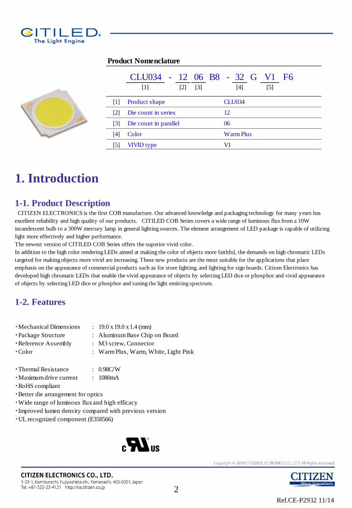
CLU034 - 12 06 B8 - 32 G V1 F6[1] [2] [3] [4] [5]
[1]
[2]
[3]
[4]
[5] V1
Product shape
Die count in series
Die count in parallel
Color
VIVID type
Product Nomenclature
CLU034
12
06
Warm Plus
Ref.CE-P2932 11/14
2. Performance Characteristics
2-1. Electro Optical Characteristics
2-2. Absolute Maximum Ratings
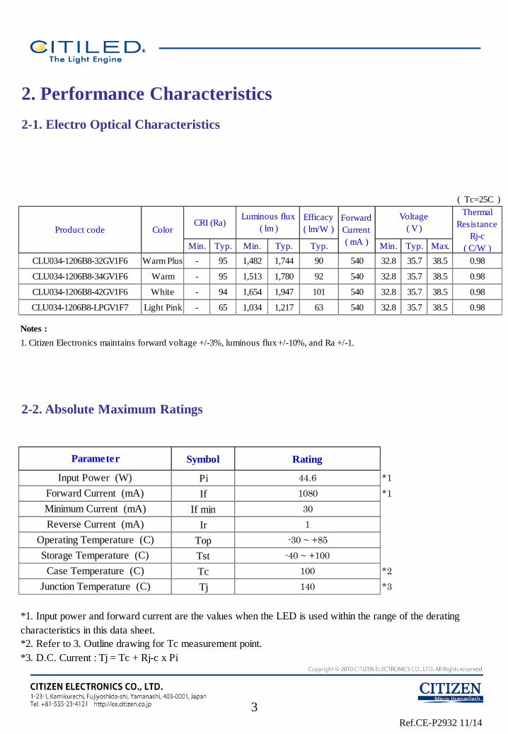
Symbol Rating
Pi 44.6 *1
If 1080 *1
If min 30
Ir 1
Top -30 ~ +85
Tst -40 ~ +100
Tc 100 *2
Tj 140 *3
*1. Input power and forward current are the values when the LED is used within the range of the derating
characteristics in this data sheet.
*2. Refer to 3. Outline drawing for Tc measurement point.
Parameter
Input Power (W)
Forward Current (mA)
Minimum Current (mA)
Reverse Current (mA)
*3. D.C. Current : Tj = Tc + Rj-c x Pi
Storage Temperature (C)
Case Temperature (C)
Junction Temperature (C)
Operating Temperature (C)
( Tc=25C )
Efficacy
( lm/W )
Min. Typ. Min. Typ. Typ. Min. Typ. Max.
CLU034-1206B8-32GV1F6 Warm Plus - 95 1,482 1,744 90 540 32.8 35.7 38.5 0.98
CLU034-1206B8-34GV1F6 Warm - 95 1,513 1,780 92 540 32.8 35.7 38.5 0.98
CLU034-1206B8-42GV1F6 White - 94 1,654 1,947 101 540 32.8 35.7 38.5 0.98
CLU034-1206B8-LPGV1F7 Light Pink - 65 1,034 1,217 63 540 32.8 35.7 38.5 0.98
Notes :
1. Citizen Electronics maintains forward voltage +/-3%, luminous flux +/-10%, and Ra +/-1.
Product code
Voltage
( V )
Forward
Current
( mA )
Thermal
Resistance
Rj-c
( C/W )
CRI (Ra)Luminous flux
( lm )Color
3
Ref.CE-P2932 11/14
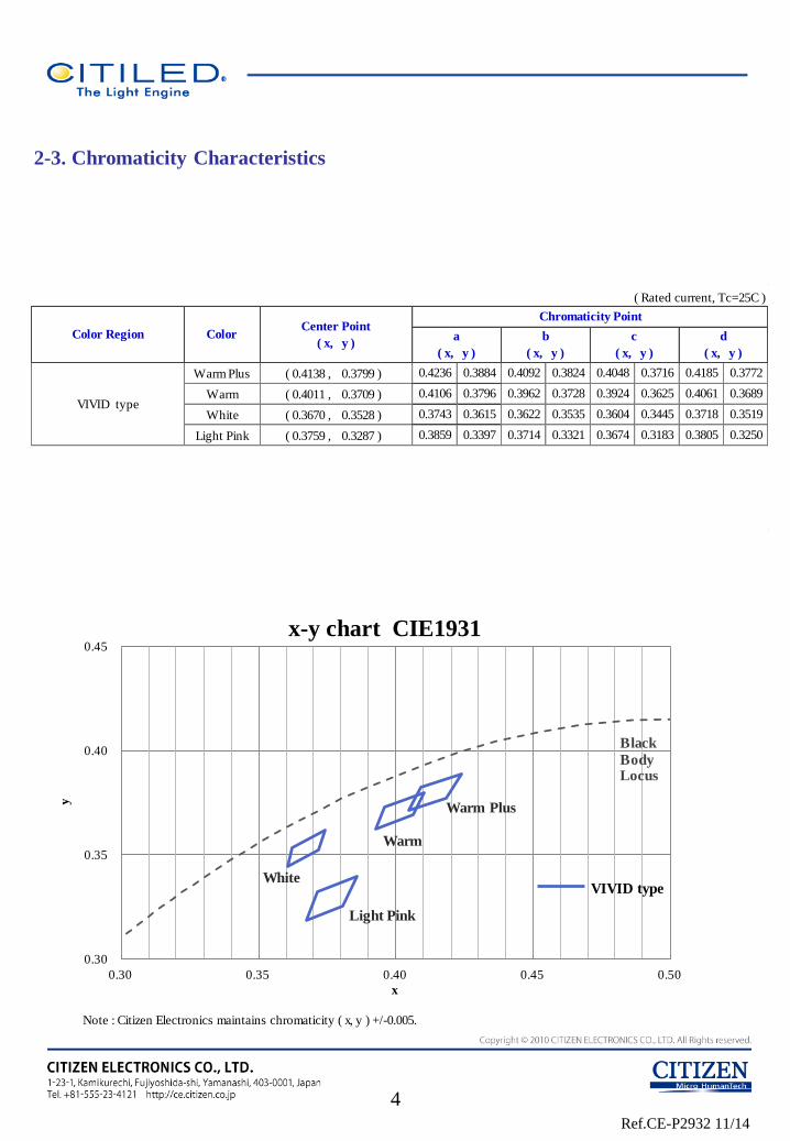
2-3. Chromaticity Characteristics
Note : Citizen Electronics maintains chromaticity ( x, y ) +/-0.005.
0.30
0.35
0.40
0.45
0.30 0.35 0.40 0.45 0.50
y
x
x-y chart CIE1931
Black
Body Locus
VIVID type
Warm Plus
Warm
White
Light Pink
4
Warm Plus ( 0.4138 , 0.3799 )
Warm ( 0.4011 , 0.3709 )
White ( 0.3670 , 0.3528 )
Light Pink ( 0.3759 , 0.3287 )
0.3884 0.4092 0.3824 0.4048
( Rated current, Tc=25C )
Color Region ColorCenter Point
( x, y )
Chromaticity Point
a
( x, y )
b
( x, y )
c
( x, y )
d
( x, y )
0.3689
0.3859 0.3397 0.3714 0.3321 0.3674 0.3183 0.3805 0.3250
0.4106 0.3796 0.3962 0.3728 0.3924
0.3445
0.3716 0.4185 0.3772
* Color region stay within MacAdam 3-step ellipse from the chromaticity center.
* The chromaticity center refers to ANSI C78.377:2011.
Please refer to ANSI C78. 377 for the chromaticity center.
0.3718 0.3519VIVID type
0.3743 0.3615 0.3622 0.3535 0.3604
0.3625 0.4061
0.4236
Ref.CE-P2932 11/14
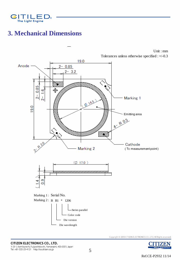
3. Mechanical Dimensions
5
Unit : mm
Tolerances unless otherwise specified : +/-0.3
( Tc measurement point )
Emitting area
Marking 1 : Serial No.
Marking 2 :
Series parallel
Color code
Die version
Die wavelength
B B1 * 1206
Ref.CE-P2932 11/14
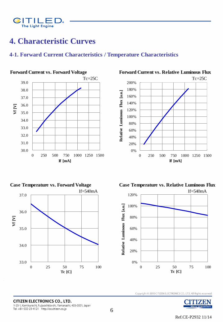
Forward Current vs. Forward Voltage Forward Current vs. Relative Luminous Flux
Tc=25C Tc=25C
Case Temperature vs. Forward Voltage Case Temperature vs. Relative Luminous Flux
If=540mA If=540mA
30.0
31.0
32.0
33.0
34.0
35.0
36.0
37.0
38.0
39.0
0 250 500 750 1000 1250 1500
Vf
[V]
If [mA]
0%
20%
40%
60%
80%
100%
120%
140%
160%
180%
200%
0 250 500 750 1000 1250 1500
Rela
tive
L
um
inou
s F
lux [
a.u
.]
If [mA]
33.0
34.0
35.0
36.0
37.0
0 25 50 75 100
Vf
[V]
Tc [C]
0%
20%
40%
60%
80%
100%
120%
0 25 50 75 100
Rela
tive
L
um
inou
s F
lux [
a.u
.]
Tc [C]
4. Characteristic Curves
4-1. Forward Current Characteristics / Temperature Characteristics
6
Ref.CE-P2932 11/14
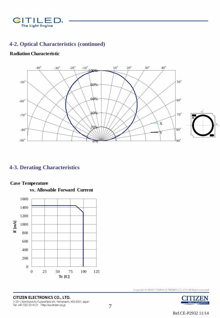
4-2. Optical Characteristics (continued)
4-3. Derating Characteristics
Case Temperature
vs. Allowable Forward Current
0
200
400
600
800
1000
1200
1400
1600
0 25 50 75 100 125
If [
mA
]
Tc [C]
7
Radiation Characteristic
0%
20%
40%
60%
80%
100%
X
Y80°
70°
60°
50°
40°30°20°10°
-80°
-70°
-60°
-50°
-20°-30°-40° -10°
90°-90°
Ref.CE-P2932 11/14
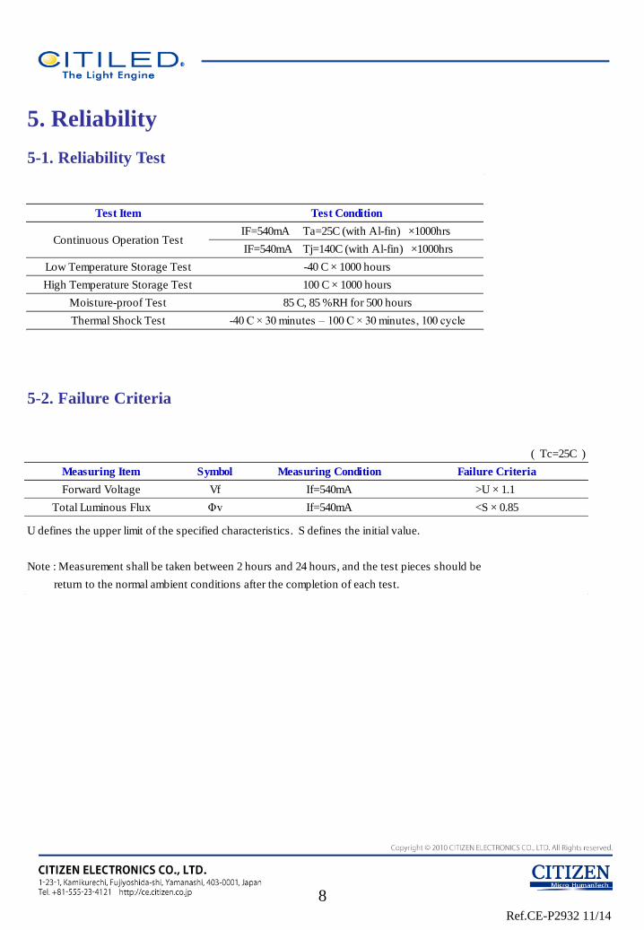
5. Reliability
5-1. Reliability Test
5-2. Failure Criteria
-40 C × 30 minutes – 100 C × 30 minutes, 100 cycle
85 C, 85 %RH for 500 hours
Thermal Shock Test
Continuous Operation Test
High Temperature Storage Test
Low Temperature Storage Test
Moisture-proof Test
Test Item
100 C × 1000 hours
-40 C × 1000 hours
Test Condition
IF=540mA Ta=25C (with Al-fin) ×1000hrs
IF=540mA Tj=140C (with Al-fin) ×1000hrs
8
( Tc=25C )
U defines the upper limit of the specified characteristics. S defines the initial value.
Note : Measurement shall be taken between 2 hours and 24 hours, and the test pieces should be
return to the normal ambient conditions after the completion of each test.
Total Luminous Flux Φv If=540mA <S × 0.85
Measuring Item Symbol Measuring Condition Failure Criteria
Forward Voltage Vf If=540mA >U × 1.1
Ref.CE-P2932 11/14
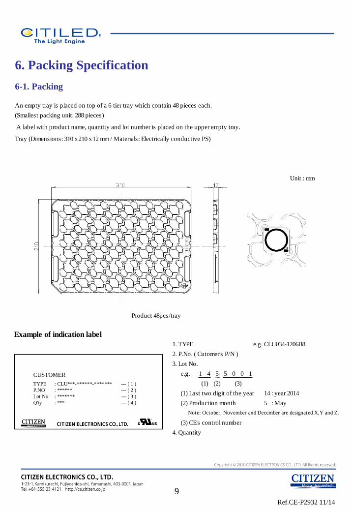
1 4 5 5 0 0 1
(2)(1) (3)
Example of indication label
1. TYPE e.g. CLU034-1206B8
2. P.No. ( Cutomer's P/N )
3. Lot No.
e.g.
4. Quantity
(1) Last two digit of the year 14 : year 2014
(2) Production month 5 : May
Note: October, November and December are designated X,Y and Z.
(3) CE's control number
6. Packing Specification
6-1. Packing
9
An empty tray is placed on top of a 6-tier tray which contain 48 pieces each.
(Smallest packing unit: 288 pieces)
A label with product name, quantity and lot number is placed on the upper empty tray.
Tray (Dimensions: 310 x 210 x 12 mm / Materials: Electrically conductive PS)
Unit : mm
Product 48pcs/tray
CUSTOMER
TYPE
P.NO
Lot No
Q'ty
: CLU***-******-*******
: ******
: *******
: ***
--- ( 1 )
--- ( 2 )
--- ( 3 )
--- ( 4 )
Ref.CE-P2932 11/14
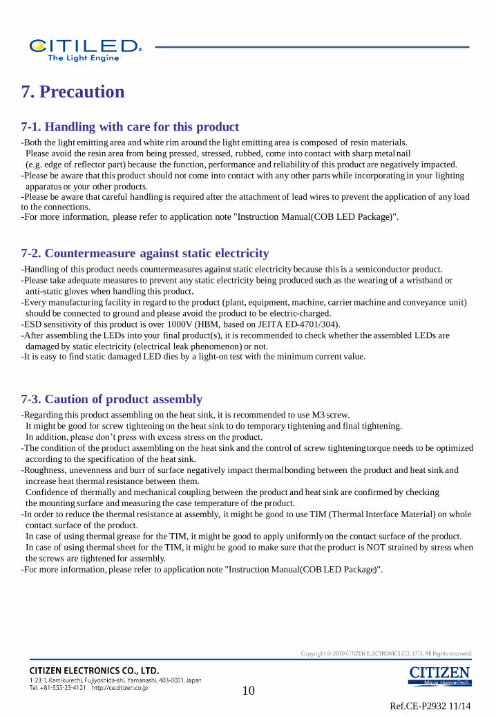
7. Precaution
7-1. Handling with care for this product
-Both the light emitting area and white rim around the light emitting area is composed of resin materials.
Please avoid the resin area from being pressed, stressed, rubbed, come into contact with sharp metal nail
(e.g. edge of reflector part) because the function, performance and reliability of this product are negatively impacted.
-Please be aware that this product should not come into contact with any other parts while incorporating in your lighting
apparatus or your other products. -Please be aware that careful handling is required after the attachment of lead wires to prevent the application of any load to the connections. -For more information, please refer to application note "Instruction Manual(COB LED Package)".
7-2. Countermeasure against static electricity
-Handling of this product needs countermeasures against static electricity because this is a semiconductor product.
-Please take adequate measures to prevent any static electricity being produced such as the wearing of a wristband or
anti-static gloves when handling this product.
-Every manufacturing facility in regard to the product (plant, equipment, machine, carrier machine and conveyance unit)
should be connected to ground and please avoid the product to be electric-charged.
-ESD sensitivity of this product is over 1000V (HBM, based on JEITA ED-4701/304).
-After assembling the LEDs into your final product(s), it is recommended to check whether the assembled LEDs are
damaged by static electricity (electrical leak phenomenon) or not. -It is easy to find static damaged LED dies by a light-on test with the minimum current value.
7-3. Caution of product assembly
-Regarding this product assembling on the heat sink, it is recommended to use M3 screw.
It might be good for screw tightening on the heat sink to do temporary tightening and final tightening.
In addition, please don’t press with excess stress on the product.
-The condition of the product assembling on the heat sink and the control of screw tightening torque needs to be optimized
according to the specification of the heat sink.
-Roughness, unevenness and burr of surface negatively impact thermal bonding between the product and heat sink and
increase heat thermal resistance between them.
Confidence of thermally and mechanical coupling between the product and heat sink are confirmed by checking
the mounting surface and measuring the case temperature of the product.
-In order to reduce the thermal resistance at assembly, it might be good to use TIM (Thermal Interface Material) on whole
contact surface of the product.
In case of using thermal grease for the TIM, it might be good to apply uniformly on the contact surface of the product.
In case of using thermal sheet for the TIM, it might be good to make sure that the product is NOT strained by stress when
the screws are tightened for assembly.
-For more information, please refer to application note "Instruction Manual(COB LED Package)".
10
Ref.CE-P2932 11/14
7-4. Thermal Design
-The thermal design to draw heat away from the LED junction is most critical parameter for an LED illumination system.
High operating temperatures at the LED junction adversely affect the performance of LED’s light output and lifetime.
Therefore the LED junction temperature should not exceed the absolute maximum rating in LED illumination system.
-The LED junction temperature while operation of LED illumination system depends upon thermal resistance of internal
LED package (Rj-c), outer thermal resistances of LED package, power loss and ambient temperature. Please take both of
the thermal design specifications and ambient temperature conditions into consideration for the setting of driving
conditions. -For more information, please refer to application note "Thermal Management", "Instruction Manual(COB LED Package)".
7-5. Driving Current
-A constant current is recommended as an applying driving current to this product.
In the case of constant voltage driving, please connect current-limiting resistor to each products in series and control
the driving current to keep under the absolute maximum rating forward current value.
-Electrical transient might apply excess voltage, excess current and reverse voltage to the product(s).
They also affect negative impact on the product(s) therefore please make sure that no excess voltage, no excess current
and no reverse voltage is applied to the product(s) when the LED driver is turn-on and/or turn-off. -For more information, please refer to application note "Driving", "Instruction Manual(COB LED Package)".
7-6. Lighting at a minimum current value
-In a case where the minimum current(IF min) is applied to the product, some of LED dice in the product might look
different in their brightness due to the individual difference of the LED dice, and they are not failed.
7-7. Electrical Safety
-This product is designed and produced according to IEC 62031:2008
(IEC 62031:2008 LED modules for general lighting. Safety specification)
-Dielectric voltage withstand test has been conducted on this product to see any failure after applying
voltage between active pads and aluminum section of the product, and to pass at least 500V.
-Considering conformity assessment for IEC62031:2008, almost all items of the specification depend upon
your final product of LED illumination system.
Therefore, please confirm with your final product for electrical safety of your product.
As well, the products comply with the criteria of IEC62031:2008 as single LED package.
11
Ref.CE-P2932 11/14
7-8. Recommended soldering Condition (This product is not adaptable to reflow process.)
-For manual soldering
Please use lead-free soldering.
Soldering shall be implemented using a soldering bit at a temperature lower than 350C, and shall be
finished within 3.5 seconds for one land.
No external force shall be applied to resin part while soldering is implemented.
Next process of soldering should be carried out after the product has return to ambient temperature.
Contacts number of soldering bit should be within twice for each terminal.
* Citizen Electronics cannot guarantee if usage exceeds these recommended conditions. Please use it after sufficient verification is carried out on your own risk if absolutely necessary. -For more information, please refer to application note "Instruction Manual(COB LED Package)".
7-9. Eye Safety
-The International Electrical Commission (IEC) published in 2006 IEC 62471
”2006 Photobiological safety of lamps and lamp systems ” which includes LEDs within its scope.
When sorting single LEDs according to IEC 62471, almost all white LEDs can be classified
as belonging to either Exempt Group (no hazard) or Risk Group 1 (low risk).
-However, Optical characteristics of LEDs such as radiant flux, spectrum and light distribution are factors
that affect the risk group determination of the LED, and especially a high-power LED, that emits light
containing blue wavelengths,
might have properties equivalent to those of Risk Group 2 (moderate risk).
-Great care should be taken when directly viewing an LED that is driven at high current, has multiple
uses as a module or when focusing the light with optical instruments, as these actions might greatly
increase the hazard to your eyes. -It is recommended to regard the evaluation of stand-alone LED packages as a reference and to evaluate your final product.
7-10. This product is not designed for usage under the following conditions.
If the product might be used under the following conditions, you shall evaluate its effect and appropriate them. In places
where the product might:
-directly and indirectly get wet due to rain and/or at place with the fear. -be damage by seawater and/or at place with the fear
-be exposed to corrosive gas (such as Cl2, H2S, NH3, SOx, NOx and so on) and/or at place with the fear. -be exposed to dust, fluid or oil and/or at place with the fear.
12
Ref.CE-P2932 11/14
8, Precautions with regard to product use
(1) This document is provided for reference purposes only so that CITIZEN ELECTRONICS' products are used as
intended. CITIZEN ELECTRONICS neither makes warranties or representations with respect to the accuracy or
completeness of the information contained in this document nor grants any license to any intellectual property rights or
any other rights of CITIZEN ELECTRONICS or any third party with respect to the information in this document.
(2) All information included in this document such as product data, diagrams, charts, is current as of the date this
document is issued.
Such information, however, is subject to change without any prior notice.
Before purchasing or using any CITIZEN ELECTRONICS' products listed in this document, please confirm the latest
product information with a CITIZEN ELECTRONICS' sales office, and formal specifications must be exchanged and
signed by both parties prior to mass production.
(3) CITIZEN ELECTRONICS has used reasonable care in compiling the information included in this document, but
CITIZEN ELECTRONICS assumes no liability whatsoever for any damages incurred as a result of errors or omissions in
the information included in this document.
(4) Absent a written signed agreement, except as provided in the relevant terms and conditions of sale for product, and to
the maximum extent allowable by law, CITIZEN ELECTRONICS assumes no liability whatsoever, including without
limitation, indirect, consequential, special, or incidental damages or loss, including without limitation, loss of profits, loss
of opportunities, business interruption and loss of data, and disclaims any and all express or implied warranties and
conditions related to sale, use of product, or information, including warranties or conditions of merchantability, fitness for
a particular purpose, accuracy of information, or no infringement.
(5) Though CITIZEN ELECTRONICS works continually to improve products' quality and reliability, products can
malfunction or fail. Customers are responsible for complying with safety standards and for providing adequate designs and
safeguards to minimize risk and avoid situations in which a malfunction or failure of a product could cause loss of human
life, bodily injury or damage to property, including data loss or corruption.
In addition, customers are also responsible for determining the appropriateness of use of any information contained in this
document such as application cases not only with evaluating by their own but also by the entire system.
CITIZEN ELECTRONICS assumes no liability for customers' product design or applications.
(6) Please contact CITIZEN ELECTRONICS' sales office if you have any questions regarding the information contained
in this document, or if you have any other inquiries.
CITIZEN Micro HumanTech is a registered trademark of Citizen Holding Co., Japan.
CITILED is a registered trademark of CITIZEN ELECTRONICS CO., LTD. Japan
13
Ref.CE-P2932 11/14
and are trademarks or registered trademarks of CITIZEN HOLDINGS CO., LTD. JAPAN.
is a trademark or a registered trademark of CITIZEN ELECTRONICS CO., LTD. JAPAN.
14