city of grand haven grand haven, michigan planning ... · drive-through business located at 901...

47
CITY OF GRAND HAVEN GRAND HAVEN, MICHIGAN PLANNING COMMISSION VIRTUAL MEETING AGENDA MAY 12, 2020 Notice and agenda of the as-needed second Planning Commission Meeting at 7:30 p.m. to be held virtually. Planning Commissioners unable to participate in the meeting are requested to contact the Community Development Department at 616-847-3490 prior to the meeting. 1. Roll Call: Tim Deiters, Ryan Galligan, Robert Grimes, Andrea Hendrick, Kevin McLaughlin, Kirsten Runschke, David Skelly, Michael Westbrook, Chair Bill Ellingboe. 2. Approval of Minutes: April 21, 2020 3. Call to the Audience – first opportunity At this time, members of the audience may address the Planning Commission on any item, whether on the agenda or not. Those addressing the Planning Commission are asked to provide their name and address and will be limited to three minutes of speaking time. The Planning Commission will hear all comments for future consideration but will not have a response at this time. Either type in your comment on the Facebook Live feed or call (616) 843-7528. If you get a busy signal or the phone is not answered, please wait, watch and call back. We will take all callers tonight. 4. Work Session A. Case 20-11: A work session to determine if the application for a Special Land Use Permit for a drive-through business (Consumers Credit Union) located at 901 South Beacon Boulevard parcel #70-03-28-155-020) is complete and ready to schedule a public hearing. B. Case 20-12: A work session to determine if the application for a Zoning Change of 427 North 6 th Street (parcel #70-03-21-302-009), 423 North 6 th Street (parcel #70-03-302-010), and 532 Jackson Avenue (parcel #70-03-21-302-008) from OT, Old Town District to C, Commercial District is complete and ready to schedule a public hearing. C. Case 20-13: Proposed text amendments to the Grand Haven zoning ordinance related to regulations governing business operations such as but not limited to sidewalk cafes and temporary use permits in an effort to aide businesses in the transition back to full operation following the pandemic. D. Case 20-09: The Planning Commission will continue to review proposed changes to the Zoning Ordinance. 5. ZBA Liaison Report 6. Community Development Manager’s Report 7. Call to the Audience – second opportunity At this time, members of the audience may address the Planning Commission on any item, whether on the agenda or not. Those addressing the Planning Commission are asked to provide their name and address and will be limited to three minutes of speaking time. The Planning Commission will hear all comments for future consideration but will not have a response at this time. Either type in your comment on the Facebook Live feed or call (616) 843-7528. If you get a busy signal or the phone is not answered, please wait, watch and call back. We will take all callers tonight. 8. Adjournment

Upload: others

Post on 17-Jun-2020

3 views

Category:

Documents


0 download

TRANSCRIPT

CITY OF GRAND HAVEN GRAND HAVEN, MICHIGAN PLANNING COMMISSION

VIRTUAL MEETING AGENDA MAY 12, 2020

Notice and agenda of the as-needed second Planning Commission Meeting at 7:30 p.m. to be held virtually. Planning Commissioners unable to participate in the meeting are requested to contact the Community Development Department at 616-847-3490 prior to the meeting. 1. Roll Call: Tim Deiters, Ryan Galligan, Robert Grimes, Andrea Hendrick, Kevin McLaughlin, Kirsten

Runschke, David Skelly, Michael Westbrook, Chair Bill Ellingboe.

2. Approval of Minutes: April 21, 2020

3. Call to the Audience – first opportunity At this time, members of the audience may address the Planning Commission on any item, whether on the agenda or not. Those addressing the Planning Commission are asked to provide their name and address and will be limited to three minutes of speaking time. The Planning Commission will hear all comments for future consideration but will not have a response at this time. Either type in your comment on the Facebook Live feed or call (616) 843-7528. If you get a busy signal or the phone is not answered, please wait, watch and call back. We will take all callers tonight.

4. Work Session

A. Case 20-11: A work session to determine if the application for a Special Land Use Permit for a

drive-through business (Consumers Credit Union) located at 901 South Beacon Boulevard parcel #70-03-28-155-020) is complete and ready to schedule a public hearing.

B. Case 20-12: A work session to determine if the application for a Zoning Change of 427 North 6th Street (parcel #70-03-21-302-009), 423 North 6th Street (parcel #70-03-302-010), and 532 Jackson Avenue (parcel #70-03-21-302-008) from OT, Old Town District to C, Commercial District is complete and ready to schedule a public hearing.

C. Case 20-13: Proposed text amendments to the Grand Haven zoning ordinance related to

regulations governing business operations such as but not limited to sidewalk cafes and temporary use permits in an effort to aide businesses in the transition back to full operation following the pandemic.

D. Case 20-09: The Planning Commission will continue to review proposed changes to the Zoning

Ordinance.

5. ZBA Liaison Report

6. Community Development Manager’s Report

7. Call to the Audience – second opportunity At this time, members of the audience may address the Planning Commission on any item, whether on the agenda or not. Those addressing the Planning Commission are asked to provide their name and address and will be limited to three minutes of speaking time. The Planning Commission will hear all comments for future consideration but will not have a response at this time. Either type in your comment on the Facebook Live feed or call (616) 843-7528. If you get a busy signal or the phone is not answered, please wait, watch and call back. We will take all callers tonight.

8. Adjournment

CITY OF GRAND HAVEN GRAND HAVEN, MICHIGAN

PLANNING COMMISSION MINUTES April 21, 2020 A special electronic meeting of the Grand Haven Planning Commission was called to order by Chair Bill Ellingboe at 7:30 p.m. via Zoom. On roll call, the following members were: Present: Tim Deiters, Ryan Galligan, Bob Grimes, Andrea Hendrick, Kevin McLaughlin, Kirsten

Runschke, David Skelly, Chair Bill Ellingboe. Absent: Mike Westbrook. Also present were Jennifer Howland, Community Development Manager, Ashley Latsch, Assistant to the City Manager, and Pat McGinnis, City Manager. Motion by Grimes, seconded by McLaughlin, to approve the March 11, 2020 regular minutes was approved unanimously by roll call vote. Call to Audience (no comments) Case 20-08: An application for a Zoning Change of 1704 South Beechtree Street (parcel #70-03-27-360-026) from OS, Office-Service District to MFR, Multiple Family Residential District. Howland introduced the case. Beth Hanis, Executive Director for Tri Cities Habitat for Humanity was available to answer questions and appreciated the opportunity to develop the property. Chair Ellingboe opened the public hearing for the case. Public Comment: None Correspondence: None Motion by Deiters, seconded by Runschke, to close the public portion of the case carried unanimously by roll call vote. No comments or concerns were voiced. All members were in support of the rezoning and the future use of the property for affordable housing. Motion by Runschke, seconded by Grimes, to recommend approval of a Zoning Change of 1704 South Beechtree Street (parcel #70-03-27-360-026) from OS, Office-Service District to MFR, Multiple Family Residential District. The motion passed on the following roll call vote: Ayes: Galligan, Hendrick, Grimes, Skelly, Deiters, McLaughlin, Runschke, Chair Ellingboe. Nays: None.

Planning Commission Minutes April 21, 2020 Page 2 of 3

Case 20-10: An application for a Site Plan Review for a new Hungry Howie’s Pizza located at 300 North Beacon Boulevard (parcel #70-03-21-327-010). Peter Oleszczuk of Midwest Construction LLC provided an overview of his proposal to redevelop the property into a Hungry Howie’s Pizza. He stated that he received great feedback from staff on the plan review. His architect Riley was also on the call if needed. Howland explained the content of the slides with the site plan and building elevations and reviewed highlights in the staff report. Deiters asked if they had considered adding a drive-thru and whether they had space to the east of the proposed building. Howland explained that a drive-through would require a special land use permit, and that it would require coordination with the adjacent property owner. Oleszczuk said that wasn’t in the plans and they only had 10 feet to the east property line. Hendrick said she was happy to see that one of the curb cuts off of Elliott Avenue was being eliminated. Runschke agreed. Skelley asked Oleszczuk for a comment on the BLP request regarding landscaping. Oleszczuk said he will comply with the Board of Light & Power’s request to avoid planting tall trees under the power lines along the north property line and coordinate with city staff. All members were happy to see that the vacant site would be redeveloped and thanked Oleszczuk for his efforts. McLaughlin appreciated that he had continued forward with the project after not receiving both variances from the Zoning Board of Appeals. Ellingboe asked if underground storage tanks had been removed. Oleszczuk said he is working with Roman Wilson from Fishbeck on a Phase 2 and environmental cleanup, and he is coordinating with the State on funding options. Motion by McLaughlin, seconded by Runschke, to approve the application for a Site Plan Review for a new Hungry Howie’s Pizza located at 300 North Beacon Boulevard (parcel #70-03-21-327-010) based on the information received and subject to the condition that landscaping along the north property line will consist of lower-growing plants to avoid the power lines was approved unanimously on roll call vote. Case 20-09: Zoning Ordinance Update Howland announced that all draft chapters are posted on the City website for the public to review and comment on. There is also an interactive zoning map that people can use to obtain a summary of proposed changes affecting a particular property. Howland reviewed comments collected to date that were included in her memo. Andy Moore of Williams & Works was also present to assist with the discussion. Chair Ellingboe asked for comments related to Chapters 3 and 4. The following is a summary of comments collected.

• 40-603B – define further by zoning district? • Consider allowing taller accessory buildings • Consider standardizing Beacon Blvd. zoning and setbacks

Planning Commission Minutes April 21, 2020 Page 3 of 3

• Review LDR and MDR zoning district near Ohio Avenue; should the boundary be the street? • Height increase – explore allowing maximum height increases in more districts. • Add graphic for accessory buildings. • Consider flexibility for dumpster enclosure section • Consider plan view for figure 3-1…hard to read • 40-310 (B) review graphic in correlation with text 3-3 and 3-4...maybe remove the door? • 40-302-02 Sidewalk cafes: seek feedback from business owners • 40-312 lighting standard 3C – allow more than one foot-candle at the property line? • Specify residential and nonresidential headings on long table of land uses. • Make ground floor office (or other non-active uses) a SLU in certain zoning districts? • Add Accessory Dwelling Unit as a special land use in MFR?

Howland asked the commission to email her additional comments and challenged the commission members to share the draft with 10 people they know to help spread the word. ZBA Liaison Report None Community Development Manager’s Report Jennifer announced that the national American Planning Association conference was available online. She also informed the commission of the cases received for the next meeting: a rezoning request for Did’s Deli and neighboring properties, and a special land use permit application for a new credit union where Grand Haven Garden House used to be on Beacon Blvd. The date of the next meeting will be determined soon. Call to the Audience – second opportunity Mike Dora, 501 Friant Street, stated that if we’re going to reduce home size it will also affect accessory building size. This should be reviewed and considered, because currently you cannot have accessory buildings that exceed the footprint of your house. This could limit the ability for a homeowner to have a reasonable size garage and a shed. Adjournment: Motion by Runschke, seconded by Hendrick, to adjourn was unanimously approved by roll call vote. The meeting adjourned at 9:42 p.m. ______________________________ Jennifer Howland Community Development Manager

G:\PLANNING\Planning Commission\Agenda & Staff Reviews\2020\Case 20-11 901 S Beacon Blvd SLU SPA\Case 20-11 901 S Beacon Blvd SLU work session 5-12-20.docx

DATE: February 6, 2020

TO: Planning Commission Members

FROM: Jennifer Howland, Community Development Manager

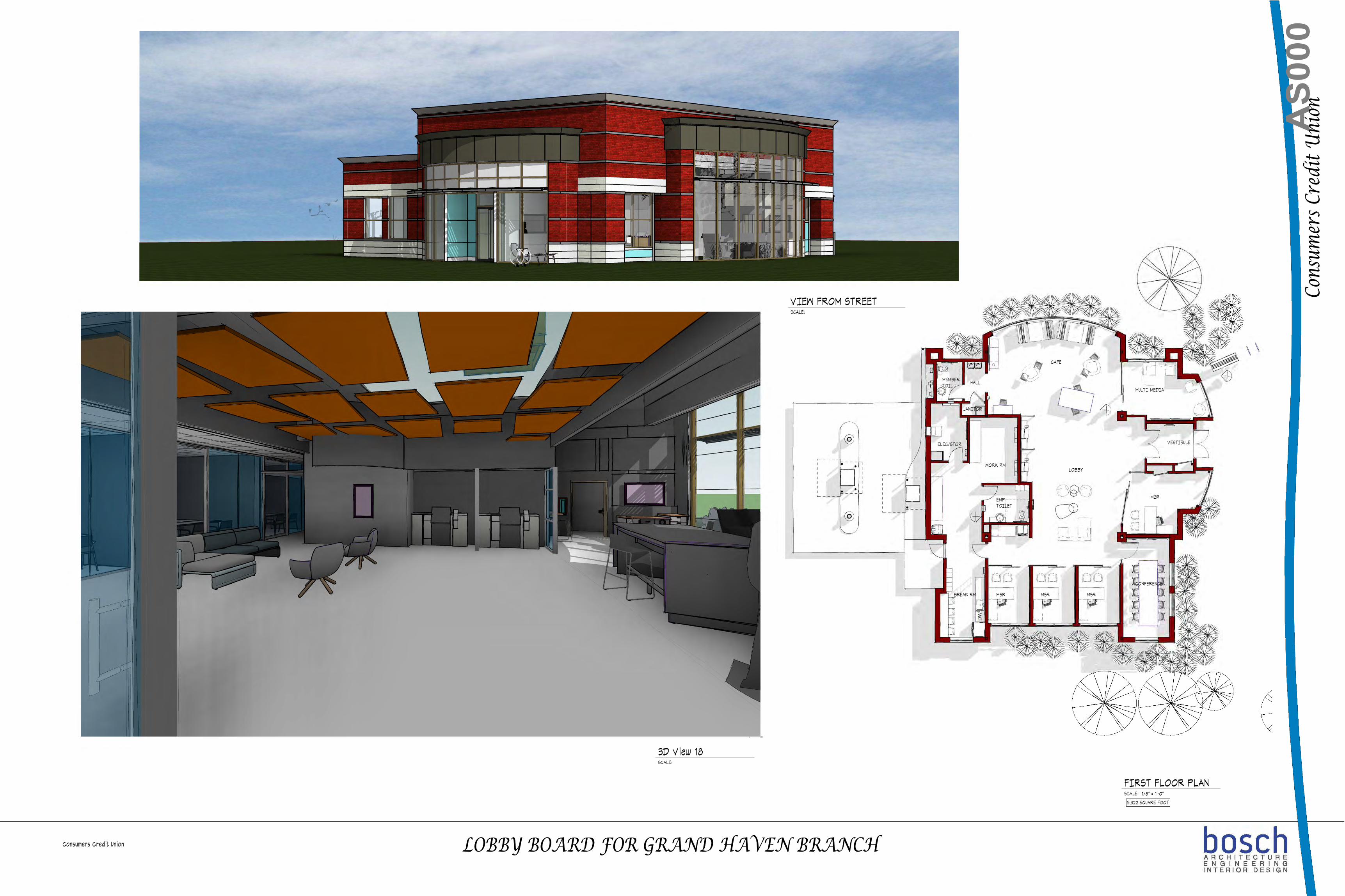
RE: Case 20-11: Special Land Use Work Session – 901 S Beacon Blvd Drive-Through Business

Current Zoning: C, Commercial District

Existing Use: Retail (former Grand Haven Garden House)

Proposed Use: Consumers Credit Union with Drive Through

1.0 Request Amy Manley of Bosch Architecture has submitted an application for a Special Land Use Permit for a Drive-Through Business located at 901 South Beacon Boulevard, parcel #70-03-28-155-020. This project also requires approval of Site Plan Review by the Planning Commission. 2.0 Special Land Use Regulations & Conditions Section 40-521 of the Zoning Ordinance provides requirements for a Drive-Through Business. Section 40-116.03 also provides general special use review standards. The applicant has provided a written explanation of how their project will meet these requirements. 3.0 Site Plan Review A full analysis of the proposed site plan will be provided by staff for the public hearing meeting. A copy of staff’s plan review comments is included as an attachment to this staff memo. 4.0 Public Hearing Staff believes the application is complete and ready to schedule a public hearing. The next available public hearing date this may be scheduled for is June 9, 2020.

19059 2020-05-05 Consumers Grand Haven Response Letter

8065 Vineyard Parkway • Kalamazoo, Michigan 49009 • ph 269-321-5151 • www.boscharch.com

May 5, 2020 Jennifer Howland, AICP Community Development Manager City of Grand Haven 519 Washington Avenue Grand Haven, MI 49417

Re: Site Plan Review Response Letter

Dear Jennifer,

Enclosed within are our responses to the site plan review dated April29, 2020 from your office, our responses are in red below:

1. You have more parking than the zoning ordinance would require. Please be prepared to explain why

you need additional parking beyond the required 11 spaces. We will be prepared to discuss with the planning commission at the electronic meeting held on May 12. The main reason is approximately 5-6 employees work at this location (parking spaces on the west side of the building). This location is a slightly larger location than average to act as a regional location for the credit union. Mortgage loan officers, Investment services, business development managers, At Work employees all travel to various offices and utilize the space as a remote office and serve members. The remainder of the spaces are for regular banking members of the credit union.

2. Is the dumpster enclosure at least 3 feet from the south property line? The dumpster enclosure is 5’ from the south property line.

3. Provide an elevation for the dumpster enclosure. Materials should match the building. Dumpster enclosure details to match the building have been added to sheet C501.

4. Provide a landscape plan. There must be a minimum of 5 feet buffer around the parking lot for plantings. The south property line appears to provide less than 5 feet of planting area. Are you keeping any of the mature trees? The south line has been revised to allow for 5’ of separation to the south property line from the drive aisle. One mature tree is being kept at the NE corner of the site. The remainder of the trees will be hard to maintain with the area of construction.

5. Provide the required narrative for the special land use permit application. The narrative for the special land use is attached.

6. Pedestrian connections between west parking spaces and building may help to avoid conflicts with drive through vehicles. A striped crosswalk has been added to the plans. The parking spaces on the west side of the building are for employee use. Employees are well aware of drive thru traffic.

7. Show the stacking in the drive through lanes with vehicle icons (separate exhibit) Vehicle representations indicating 3 cars per lane have been added to sheet C001. The credit union utilizes ITM machines (similar to an ATM) but allows for remote tellers to help the members.

19059 2020-05-05 Consumers Grand Haven Response Letter

8065 Vineyard Parkway • Kalamazoo, Michigan 49009 • ph 269-321-5151 • www.boscharch.com

8. Provide signage details if available. Approximate signage location is shown on the plans. Typically, this is handled by the GC and the credit union as part of a separate sign permit application.

9. Simplify the building elevation sheets to show how you calculated the transparency (grade to ceiling height). Revised elevation sheets have been attached.

Public Works Review Right-of-Ways Review:

1) A $100.00 Right-of-Way permit must be obtained before any Right-of-Way work is performed. Bowman Street is a City Right-of-Way. This will be handled by the GC, once the project is approved and moving forward.

2) A Right-of-Way permit is also required for the demo of the existing building. The demolition contractor will be handled this when they are ready to demolish the old structures.

Public Water Review: 1) The domestic water meter should be located in the mechanical room. No plans were given showing the meter

location. The City requires the meter to be located inside the building 10 to 18 inches from an exterior wall. Water is shown entering the building at the southwest corner of the building. A meter will be provided matching the City of Grand Haven’s requirements.

2) The proposed plan shows the water service running to the north side of the building. There is a second water service including a meter pit to the south of the property that will need to be removed and capped at the water main. Understood, is there a location for this, it was not noted on any of the information we received.

3) A $50.00 water permit must be obtained before any service connections are made. Water and sewer fees are to be determined based off of current and future water usage. Water use will be determined prior to permit approval. Understood, GC will handle this once project is kicked off.

4) A $50.00 water permit must be obtained to perform the cut and cap of the water service at the curb stop in the Right-of-Way prior to any demolition of the existing building. Understood, demolition contractor will handle this prior to demolition occurring.

Public Sewer Review: 1) The proposed plans show the sewer lateral running towards Bowman Ct. It is unknown at this time if there is

a sewer main running down Bowman Ct. Public Works will verify the sewer main as soon as possible. Thank you, please let us know so that we may update our plans accordingly.

2) A $75.00 Sewer permit must be obtained before any sewer work is performed. Water and sewer fees are to be determined based off of current and future water usage. Sewer fees will be determined prior to permit approval. Understood, GC will handle this once project is kicked off.

3) A $75.00 Sewer permit must be obtained to perform the cut and cap of the sewer lateral at the Right-of-Way line prior to any demolition of the existing building. Understood, demolition contractor will handle this prior to demolition occurring.

Storm Water Review: 1) The storm water system improvements will require a $50.00 Storm Water Permit.

Understood, GC will handle this once project is kicked off.

19059 2020-05-05 Consumers Grand Haven Response Letter

8065 Vineyard Parkway • Kalamazoo, Michigan 49009 • ph 269-321-5151 • www.boscharch.com

If you have you have any additional questions or comments, you can contact me via email at or [email protected] or at 269-321-5151. Sincerely,

Nicholas J. Loeks, PE

Special Land Use Submittal Narrative: 


The proposed Consumers Credit Union will be replacing the existing Grand Haven Garden House at 901 

S. Beacon Blvd.  The site is surrounded by a Taco Bell, Automatic Spring Products Corporation, and Papa 

Murphy’s Take ‘n’ Bake Pizza.   Within the immediate vicinity of the area also exists the Seaway Party 

Store, Kentucky Fried Chicken and a Panera Bread.   

Consumers Credit Union offers a range of personal and business banking services.  This particular site 

will contain two drive thrus with ITM service as well as face to face service.  Teller services are typically 

available from 9am to 7pm Monday through Friday, and 9am to 1pm on Saturdays.  There are 6 stacking 

places provided as required by the City of Grand Haven Ordinances.  A pedestrian walkway is located to 

allow for pedestrians to safely cross the drive thru from the parking lot to the building.   

The building will consist mainly of dark red Bowerstown brick and cast stone face.  The north and east 

sides of the building facing S. Beacon Blvd and Bowman Ct. both have significant glass windows 

exceeding the 60% transparency requirement.   

Landscaping will meet the City of Grand Haven ordinances, including canopy, evergreen and 

intermediate trees.  The landscaping will also include evergreen and deciduous shrubs along with 

ornamental grasses and perennials.  The parking lot boundaries will contain a buffer at minimum of 5’ 

for plantings.  The building will be fully landscaped as well.   

In conclusion, the Consumers Credit Union has been designed to be consistent with the existing 

character in the general vicinity of the area.  The operation and maintenance shall also be consistent 

with the existing character in the general vicinity of the area.  The Consumers Credit Union shall also 

meet the intent and purpose of the zoning ordinance and comply with the City of Grand Haven Code of 

Ordinances.   


19059JOB NUMBER

901 S

Bea

con

Blvd

Gran

d H

aven

, Mic

higa

n 49

417

This drawing, as an instrument of service, is owned byBosch Architecture, Inc. Reproduction of this document isprohibited without express authorization from the Architect.Ó 2014 Bosch Architecture Inc

Cons

umer

s Cre

dit U

nion

CD001

SITE DEMOLITION

PLAN

2020-01-17 RELEASED FOR DEMO

AutoCAD SHX Text
8065 Vineyard Parkway Kalamazoo, Michigan 49009 ph: 269-321-5151 www.boscharch.com
AutoCAD SHX Text
ENGINEERINGNGINEERINGGINEERINGINEERINGNEERINGEERINGERINGRINGINGNGG
AutoCAD SHX Text
INTERIOR DESIGNNTERIOR DESIGNTERIOR DESIGNERIOR DESIGNRIOR DESIGNIOR DESIGNOR DESIGNR DESIGN DESIGNDESIGNESIGNSIGNIGNGNN
AutoCAD SHX Text
ARCHITECTURERCHITECTURECHITECTUREHITECTUREITECTURETECTUREECTURECTURETUREUREREE
AutoCAD SHX Text
ISSUED
AutoCAD SHX Text
T
AutoCAD SHX Text
16"MAPLE
AutoCAD SHX Text
10"MAPLE
AutoCAD SHX Text
X
AutoCAD SHX Text
GRAVEL
AutoCAD SHX Text
ELEC. MTR.
AutoCAD SHX Text
BLACKTOP
AutoCAD SHX Text
COOLER AREA
AutoCAD SHX Text
GAS MTR.
AutoCAD SHX Text
ELEC. MTR.
AutoCAD SHX Text
19059CD001.dwg
AutoCAD SHX Text
EXIST 16" MAPLE TO REMAIN
AutoCAD SHX Text
DEMOLISH ENTIRE EXISTING GREENHOUSE. REMOVE FROM SITE
AutoCAD SHX Text
REMOVE EXISTING PATIO PAVERS
AutoCAD SHX Text
REMOVE EXISTING PATIO PAVERS
AutoCAD SHX Text
REMOVE EXISTING STONE PAVERS
AutoCAD SHX Text
REMOVE EXISTING WOOD DECK
AutoCAD SHX Text
REMOVE EXISTING WOOD RAMP
AutoCAD SHX Text
REMOVE EXISTING CONCRETE
AutoCAD SHX Text
REMOVE EXISTING PERGOLA
AutoCAD SHX Text
REMOVE EXISTING PATIO PAVERS
AutoCAD SHX Text
REMOVE EXISTING CHAIN LINK FENCE AND GATE
AutoCAD SHX Text
REMOVE EXISTING PERGOLA
AutoCAD SHX Text
DEMOLISH ENTIRE EXISTING 2-STY. HOUSE. REMOVE FROM SITE
AutoCAD SHX Text
DEMOLISH ENTIRE EXISTING BARN. REMOVE FROM SITE
AutoCAD SHX Text
REMOVE EXISTING VINYL FENCE
AutoCAD SHX Text
REMOVE EXISTING GAZEBO
AutoCAD SHX Text
REMOVE EXIST WOOD FENCE
AutoCAD SHX Text
REMOVE EXIST 10" MAPLE
AutoCAD SHX Text
REMOVE EXIST GATE
AutoCAD SHX Text
REMOVE EXIST STORAGE SHED
AutoCAD SHX Text
REMOVE EXIST WOOD WALLS
AutoCAD SHX Text
REMOVE EXIST CHAIN-LINK FENCE
AutoCAD SHX Text
REMOVE EXIST WOOD WALLS
AutoCAD SHX Text
REMOVE EXISTING POWER POLE
AutoCAD SHX Text
REMOVE EXISTING POWER POLE
AutoCAD SHX Text
REMOVE EXISTING VINYL FENCE
AutoCAD SHX Text
REMOVE EXIST PAVERS
AutoCAD SHX Text
REMOVE EXISTING CONCRETE
AutoCAD SHX Text
REMOVE EXISTING CONCRETE
AutoCAD SHX Text
REMOVE EXISTING ELEC. METER
AutoCAD SHX Text
REMOVE EXIST CONCRETE
AutoCAD SHX Text
REMOVE EXISTING STONE PAVERS
AutoCAD SHX Text
REMOVE EXISTING PAVING TO PROPERTY LINE
AutoCAD SHX Text
REMOVE EXISTING BITUMINOUS PAVEMENT
AutoCAD SHX Text
REMOVE EXISTING CONCRETE
AutoCAD SHX Text
REMOVE EXISTING GAS MTR.
AutoCAD SHX Text
REMOVE EXIST ELEC. MTR.
AutoCAD SHX Text
REMOVE EXISTING GRAVEL
AutoCAD SHX Text
DEMOLISH ENTIRE EXISTING BITUMINOUS PAVEMENT ON PROPERTY
AutoCAD SHX Text
REMOVE EXISTING CATCH BASIN
AutoCAD SHX Text
REMOVE EXIST 4" W PIPE
AutoCAD SHX Text
REMOVE EXIST 8" SE PIPE
AutoCAD SHX Text
REMOVE EXIST FISH POND
AutoCAD SHX Text
SAWCUT BIT. PAVEMENT
AutoCAD SHX Text
SAWCUT BIT. PAVEMENT
AutoCAD SHX Text
SAWCUT AT PROPERTY LINE AS NECESSARY
AutoCAD SHX Text
EXISTING CURBING TO REMAIN
AutoCAD SHX Text
EXISTING CURBING TO REMAIN
AutoCAD SHX Text
EXISTING POWER POLE TO REMAIN
AutoCAD SHX Text
REMOVE EXISTING POWER POLE
AutoCAD SHX Text
EXISTING SIDEWALK TO REMAIN
AutoCAD SHX Text
EXISTING DRIVE TO REMAIN
AutoCAD SHX Text
SITE DEMOLITION NOTES 1. REMOVAL OF EXISTING UTILITIES, REMOVAL OF EXISTING UTILITIES, STRUCTURES AND SLABS SHALL BE AS SHOWN ON THE CONSTRUCTION DRAWINGS. IF REMOVAL LIMITS ARE NOT SHOWN, THEY SHALL BE THE MINIMUM REQUIRED TO COMPLETE THE PROJECT. 2. DISCONNECTS OF ALL UTILITIES TO BE DISCONNECTS OF ALL UTILITIES TO BE REMOVED SHALL BE BY THE TRADE INVOLVED OR THE APPROPRIATE UTILITY CO. AS DIRECTED BY THE GENERAL CONTRACTOR. 3. DISPOSAL OF MATERIAL REMOVED SHALL DISPOSAL OF MATERIAL REMOVED SHALL BE OFF SITE BY THE GENERAL CONTRACTOR. 4. REMOVE ALL FOOTINGS, FOUNDATIONS, AND REMOVE ALL FOOTINGS, FOUNDATIONS, AND UNDERGROUND UTILITIES AND DISPOSE OFF SITE. 5. ONCE DEMO IS COMPLETE SPREAD ONCE DEMO IS COMPLETE SPREAD STOCKPILED TOPSOIL BACK OVER SITE AND SEED. SUPPLEMENT TOPSOIL AS NEEDED MINIMUM 1" DEEP. 6. ITEMS TO BE KEPT FOR THE OWNER ARE AS ITEMS TO BE KEPT FOR THE OWNER ARE AS FOLLOWS: 1. COPULA 2. WEATHERVANE
AutoCAD SHX Text
REMOVE BRICK PATIO
AutoCAD SHX Text
VERIFY WITH POWER CO.
AutoCAD SHX Text
S BEACON BLVD
AutoCAD SHX Text
PUSH ANY TOPSOIL OFF SITE AREAS AND STOCKPILE FOR RESEEDING ON SITE
AutoCAD SHX Text
SCALE: 1" =
AutoCAD SHX Text
SITE DEMOLITION PLAN
AutoCAD SHX Text
20'
AutoCAD SHX Text
N
AutoCAD SHX Text
BOWMAN CT.
AutoCAD SHX Text
RELOCATE EXISTING COMM. RISER
AutoCAD SHX Text
REMOVE EXISTING CONCRETE

19059JOB NUMBER

901 S

Bea

con

Blvd

Gran

d H

aven

, Mic

higa

n 49

417

This drawing, as an instrument of service, is owned byBosch Architecture, Inc. Reproduction of this document isprohibited without express authorization from the Architect.Ó 2014 Bosch Architecture Inc

Cons

umer

s Cre

dit U

nion

C001

CONCEPTUAL SITE PLAN

AutoCAD SHX Text
8065 Vineyard Parkway Kalamazoo, Michigan 49009 ph: 269-321-5151 www.boscharch.com
AutoCAD SHX Text
ENGINEERINGNGINEERINGGINEERINGINEERINGNEERINGEERINGERINGRINGINGNGG
AutoCAD SHX Text
INTERIOR DESIGNNTERIOR DESIGNTERIOR DESIGNERIOR DESIGNRIOR DESIGNIOR DESIGNOR DESIGNR DESIGN DESIGNDESIGNESIGNSIGNIGNGNN
AutoCAD SHX Text
ARCHITECTURERCHITECTURECHITECTUREHITECTUREITECTURETECTUREECTURECTURETUREUREREE
AutoCAD SHX Text
ISSUED
AutoCAD SHX Text
19059C001.dwg
AutoCAD SHX Text
2020-04-17 SITE PLAN REVIEW
AutoCAD SHX Text
2020-05-05 SITE PLAN REVISIONS
AutoCAD SHX Text
SCALE: 1" =
AutoCAD SHX Text
CONCEPTUAL SITE PLAN
AutoCAD SHX Text
20'
AutoCAD SHX Text
N
AutoCAD SHX Text
DUMPSTER ENCLOSURE
AutoCAD SHX Text
NIGHT DROP
AutoCAD SHX Text
ITM
AutoCAD SHX Text
ITM
AutoCAD SHX Text
S05%%d19'26"E 116.04'
AutoCAD SHX Text
S82%%d36'18"E 149.19'
AutoCAD SHX Text
BOWMAN COURT
AutoCAD SHX Text
S. BEACON BLVD.
AutoCAD SHX Text
T
AutoCAD SHX Text
T
AutoCAD SHX Text
16"MAPLE
AutoCAD SHX Text
G
AutoCAD SHX Text
W
AutoCAD SHX Text
BENCHMARK ELEVATION 607.01 TOP OF BOAT SPIKE IN SE SIDE OF POWER POLE
AutoCAD SHX Text
24" CURB & GUTTER (TYP.)
AutoCAD SHX Text
BLACKTOP
AutoCAD SHX Text
BLACKTOP
AutoCAD SHX Text
BLACKTOP
AutoCAD SHX Text
S88%%d06'16"W 247.94'
AutoCAD SHX Text
N88%%d11'24"E 91.03'
AutoCAD SHX Text
N00%%d46'31"W 140.08'
AutoCAD SHX Text
SET CAPPED IRON AT COMPUTED LOCATION, ALSO FOUND A REROD ±1' SOUTH OF SET IRON
AutoCAD SHX Text
SET MAG NAIL
AutoCAD SHX Text
P.O.B.
AutoCAD SHX Text
STANDARD PARKING STALL STRIPING TO BE YELLOW, TYP.
AutoCAD SHX Text
BARRIER FREE PARKING STALL STRIPING TO BE BLUE, TYP.
AutoCAD SHX Text
1 1/2" BASE COURSE 1 1/2" TOP COURSE BITUM. PAVING SEE DTL 9/C501
AutoCAD SHX Text
3,322 SF +/- FOOTPRINT CONSUMERS CREDIT UNION FFE = 605.5'
AutoCAD SHX Text
SITE INFORMATION 1. PARCEL ADDRESS: 901 S. BEACON BLVD PARCEL ADDRESS: 901 S. BEACON BLVD GRAND HAVEN, MI 49417 2. OWNER: CONSUMERS CREDIT UNION OWNER: CONSUMERS CREDIT UNION CONSUMERS CREDIT UNION 7200 ELM VALLEY DRIVE KALAMAZOO, MI 49009 3. ARCHITECT: BOSCH ARCHITECTURE ARCHITECT: BOSCH ARCHITECTURE 8065 VINEYARD PKWY KALAMAZOO, MI. 49009 (269) 321-5151 (269) 321-5151 4. SURVEY: EXXEL SURVEY: EXXEL EXXEL 5. ZONING: C - COMMERCIAL ZONING: C - COMMERCIAL 6. PROPOSED LAND USE: COMMERCIAL - CREDIT PROPOSED LAND USE: COMMERCIAL - CREDIT UNION 7. SITE AREA: 29,991 SF +/- SITE AREA: 29,991 SF +/- 29,991 SF +/- 0.70 ACRES +/- 8. LAND USE PERCENT (%): BUILDINGS: 12% LAND USE PERCENT (%): BUILDINGS: 12% BUILDINGS: 12% PAVEMENTS: 49% PAVEMENTS: 49% GREEN: 39% 9. BUILDING TYPE: 3,322 SF +/- BUILDING TYPE: 3,322 SF +/- 3,322 SF +/- CREDIT UNION 10. BUILDING HEIGHT: 20'0" ACTUAL BUILDING HEIGHT: 20'0" ACTUAL 20'0" ACTUAL 11. PARKING REQUIRED: PARKING REQUIRED: BANK: 1 STALL PER 300 SF OF GROSS FLOOR SPACE (GFS) 3,322 SF GFS / 300 = 11 STALLS REQ. 19 STALLS PROVIDED (1 B.F.) DRIVE THROUGH FACILITY STACKING: 3 STACKING SPACES PER TELLER/ATM LANE 2 DRIVE THROUGH LANES X 3 = 6 STACKING SPACES 6+ STACKING SPACES PROVIDED 12. LANDSCAPING REQ: SEE L001 LANDSCAPING REQ: SEE L001 SEE L001 13. LEGAL DESCRIPTION: SEE TS001 LEGAL DESCRIPTION: SEE TS001 SEE TS001 13. SITE LIGHTING: SEE C004 SITE LIGHTING: SEE C004 SEE C004 14. OCC. CLASSIFICATION: B OCC. CLASSIFICATION: B B 15. CONSTRUCTION TYPE: VB CONSTRUCTION TYPE: VB VB 16. FIRE SPRINKLING: NOT SPRINKLEDFIRE SPRINKLING: NOT SPRINKLEDNOT SPRINKLED
AutoCAD SHX Text
REQUIRED LANDSCAPE IS SHOWN ON LANDSCAPE PLAN. SEE L001 FOR PLANTING DETAILS. APPROPRIATE PERMITS TO BE OBTAINED FROM THE CITY OF GRAND HAVEN. AN EMERGENCY KNOX BOX FOR FIRE DEPARTMENT ACCESS WILL BE PROVIDED IF REQUIRED. KNOX BOX LOCATION TO BE DETERMINED UPON SUBMITTAL OF BUILDING PLANS, IF REQUIRED. A FIREFIGHTER RIGHT-TO-KNOW AND HAZARDOUS MATERIALS RIGHT TO KNOW FORMS TO BE SUBMITTED PRIOR TO ISSUANCE OF A BUILDING PERMIT. IF REQUIRED.
AutoCAD SHX Text
GENERAL NOTES (SITE WORK) 1. SITE PREPARATION: a. ALL EROSION AND SEDIMENTATION CONTROL MEASURES SHALL BE PERFORMED BY THE CONTRACTOR IN COMPLIANCE WITH PART 91 OF PUBLIC ACT 451 OF 1994. 2. EARTHWORK: a. CALL MISS DIG AT 1-800-482-7171 BEFORE BEGINNING EXCAVATION. b. EXCAVATION SHALL BE LEVEL TO EXACT DEPTHS AND DIMENSIONS INDICATED ON DRAWINGS. c. SITE SHALL BE FINE GRADED BEFORE PLACING TOP SOIL OR GRANULAR BASE MATERIAL. d. EXTERIOR SURFACE DRAINAGE SHALL BE AWAY FROM BUILDINGS, 5% 10'-0" OUT FROM BLDG. e. ALL TOPOGRAPHICAL INFORMATION WAS FURNISHED BY EXXEL AND ASSUMED CORRECT. THE CONTRACTOR SHALL VERIFY ALL EXISTING AND NEW GRADES PRIOR TO COMMENCEMENT OF ANY WORK. THIS OFFICE SHALL NOT BE HELD RESPONSIBLE FOR ANY MISSING OR ERRONEOUS INFORMATION.
AutoCAD SHX Text
ALL PAVEMENT MARKINGS AND TRAFFIC SIGNS MUST CONFORM TO THE STANDARDS SET FORTH IN THE CURRENT EDITION OF THE MICHIGAN MANUAL OF UNIFORM TRAFFIC CONTROL DEVICES.
AutoCAD SHX Text
P.O.B.
AutoCAD SHX Text
BENCHMARK ELEVATION 607.01
AutoCAD SHX Text
TOP OF BOAT SPIKE IN SE SIDE
AutoCAD SHX Text
OF POWER POLE
AutoCAD SHX Text
PROJECT SITE LOCATION
AutoCAD SHX Text
8
AutoCAD SHX Text
C501
AutoCAD SHX Text
8
AutoCAD SHX Text
C501
AutoCAD SHX Text
8
AutoCAD SHX Text
C501
AutoCAD SHX Text
8
AutoCAD SHX Text
C501
AutoCAD SHX Text
8
AutoCAD SHX Text
C501
AutoCAD SHX Text
8
AutoCAD SHX Text
C501
AutoCAD SHX Text
2
AutoCAD SHX Text
C501
AutoCAD SHX Text
6
AutoCAD SHX Text
C501
AutoCAD SHX Text
7
AutoCAD SHX Text
C501
AutoCAD SHX Text
4
AutoCAD SHX Text
C501
AutoCAD SHX Text
DIRECTIONAL ARROWS FOR ILLUSTRATING TRAFFIC FLOW, NOT TO BE PAINTED U.N.O.
AutoCAD SHX Text
STANDARD PARKING STALL STRIPING TO BE YELLOW, TYP.
AutoCAD SHX Text
STANDARD PARKING STALL STRIPING TO BE YELLOW, TYP.
AutoCAD SHX Text
CB
AutoCAD SHX Text
CB
AutoCAD SHX Text
B
AutoCAD SHX Text
CB
AutoCAD SHX Text
1
AutoCAD SHX Text
C501
AutoCAD SHX Text
1
AutoCAD SHX Text
C501
AutoCAD SHX Text
1
AutoCAD SHX Text
C501
AutoCAD SHX Text
1
AutoCAD SHX Text
C501
AutoCAD SHX Text
4
AutoCAD SHX Text
C501
AutoCAD SHX Text
12
AutoCAD SHX Text
C501
AutoCAD SHX Text
13
AutoCAD SHX Text
C501
AutoCAD SHX Text
DUB DOWN CURB
AutoCAD SHX Text
CONCRETE/BITUMINOUS SURFACE KEY BITUMINOUS SURFACE CONCRETE SURFACE
AutoCAD SHX Text
MH
AutoCAD SHX Text
MW
AutoCAD SHX Text
AC
AutoCAD SHX Text
T
AutoCAD SHX Text
T
AutoCAD SHX Text
T
AutoCAD SHX Text
W
AutoCAD SHX Text
SA
AutoCAD SHX Text
E
AutoCAD SHX Text
T
AutoCAD SHX Text
ST
AutoCAD SHX Text
G
AutoCAD SHX Text
G
AutoCAD SHX Text
W
AutoCAD SHX Text
MANHOLE
AutoCAD SHX Text
UNDERGROUND TELEPHONE MARKER
AutoCAD SHX Text
UNDERGROUND TELEPHONE MARKER
AutoCAD SHX Text
AIR CONDITIONING UNIT
AutoCAD SHX Text
ELECTRIC BOX / TRANSFORMER
AutoCAD SHX Text
MONITOR WELL
AutoCAD SHX Text
PHONE BOOTH
AutoCAD SHX Text
FLAG POLE
AutoCAD SHX Text
LIGHT POLE
AutoCAD SHX Text
UTILITY POLE W/ LIGHT
AutoCAD SHX Text
CATCH BASIN/CURB INLET
AutoCAD SHX Text
ELEC CO MANHOLE
AutoCAD SHX Text
PHONE CO MANHOLE
AutoCAD SHX Text
SANITARY SEWER MANHOLE
AutoCAD SHX Text
STORM SEWER MANHOLE
AutoCAD SHX Text
WATER MANHOLE
AutoCAD SHX Text
UTILITY POLE
AutoCAD SHX Text
SIGN
AutoCAD SHX Text
TREE TO BE REMOVED
AutoCAD SHX Text
EXIST TREE TO REMAIN
AutoCAD SHX Text
CONCRETE BOLLARD
AutoCAD SHX Text
NEW TREE
AutoCAD SHX Text
SOIL BORING
AutoCAD SHX Text
FIRE HYDRANT
AutoCAD SHX Text
WATER VALVE
AutoCAD SHX Text
BASKETBALL NET
AutoCAD SHX Text
PARKING METER
AutoCAD SHX Text
UNDERGROUND GAS MARKER
AutoCAD SHX Text
GAS METER
AutoCAD SHX Text
MAIL BOX
AutoCAD SHX Text
GAS VALVE
AutoCAD SHX Text
WATER METER
AutoCAD SHX Text
TYPICAL MATERIALS, SYMBOLS AND INDICATIONS
AutoCAD SHX Text
OVERHEAD ELEC LINE
AutoCAD SHX Text
UNDERGROUND ELEC LINE
AutoCAD SHX Text
GAS LINE
AutoCAD SHX Text
WATER LINE
AutoCAD SHX Text
FENCE LINE
AutoCAD SHX Text
CENTER LINE
AutoCAD SHX Text
PROPERTY LINE
AutoCAD SHX Text
STORM LINE
AutoCAD SHX Text
SANITARY LINE
AutoCAD SHX Text
EXIST SPOT GRADE
AutoCAD SHX Text
FINISH GRADE
AutoCAD SHX Text
EXIST SANITARY LINE
AutoCAD SHX Text
EXIST STORM LINE
AutoCAD SHX Text
EXIST UNDERGROUND ELEC LINE
AutoCAD SHX Text
EXIST GAS LINE
AutoCAD SHX Text
EXIST WATER LINE
AutoCAD SHX Text
EXIST OVERHEAD ELEC LINE
AutoCAD SHX Text
TELEPHONE LINE
AutoCAD SHX Text
EXIST TELEPHONE LINE
AutoCAD SHX Text
YARD LAMP + POLE
AutoCAD SHX Text
NEW SHRUB
AutoCAD SHX Text
NEW FLAG POLE
AutoCAD SHX Text
10
AutoCAD SHX Text
C501
AutoCAD SHX Text
22
AutoCAD SHX Text
C501
AutoCAD SHX Text
23
AutoCAD SHX Text
C501
AutoCAD SHX Text
24
AutoCAD SHX Text
C501
AutoCAD SHX Text
21
AutoCAD SHX Text
C501
AutoCAD SHX Text
10
AutoCAD SHX Text
C501
AutoCAD SHX Text
POINT OF BEGINNING
AutoCAD SHX Text
CB
AutoCAD SHX Text
18
AutoCAD SHX Text
C501
AutoCAD SHX Text
1
AutoCAD SHX Text
C501
AutoCAD SHX Text
DUB DOWN CURB
AutoCAD SHX Text
5
AutoCAD SHX Text
C501
AutoCAD SHX Text
5
AutoCAD SHX Text
C501
AutoCAD SHX Text
3
AutoCAD SHX Text
C501
AutoCAD SHX Text
14
AutoCAD SHX Text
C501
AutoCAD SHX Text
1
AutoCAD SHX Text
1
AutoCAD SHX Text
CROSS WALK STRIPING
AutoCAD SHX Text
1
AutoCAD SHX Text
NEW GROUND/MONUMENT SIGN 12.5' MIN. AWAY FROM PROPERTY LINE MAX 32 SF AREA & 6 FT TALL VERIFY EXACT LOCATION WITH SIGN COMPANY AND PERMITTING REQ'S
AutoCAD SHX Text
1
AutoCAD SHX Text
1

C002

SITE UTILITY AND

GRADING PLAN

19059JOB NUMBER

901 S

Bea

con

Blvd

Gran

d H

aven

, Mic

higa

n 49

417

This drawing, as an instrument of service, is owned byBosch Architecture, Inc. Reproduction of this document isprohibited without express authorization from the Architect.Ó 2014 Bosch Architecture Inc

Cons

umer

s Cre

dit U

nion

B

A

B

A

AutoCAD SHX Text
19059C002.dwg
AutoCAD SHX Text
2020-04-17 SITE PLAN REVIEW
AutoCAD SHX Text
2020-05-05 SITE PLAN REVISIONS
AutoCAD SHX Text
S05%%d19'26"E 116.04'
AutoCAD SHX Text
S82%%d36'18"E 149.19'
AutoCAD SHX Text
D= N00%%D46'31"W 263.56'
AutoCAD SHX Text
S88%%d06'16"W 255.89'
AutoCAD SHX Text
BOWMAN COURT
AutoCAD SHX Text
S. BEACON BLVD.
AutoCAD SHX Text
T
AutoCAD SHX Text
T
AutoCAD SHX Text
STORM MANHOLE TOP 605.53 CONC. INV. W. (MOSTLY FULL OF DIRT) BOTTOM 601.73 (PREV. EXXEL TOPO HAS 8" W. 601.39 6" NNE 604.14)
AutoCAD SHX Text
G
AutoCAD SHX Text
W
AutoCAD SHX Text
BENCHMARK ELEVATION 607.01 TOP OF BOAT SPIKE IN SE SIDE OF POWER POLE
AutoCAD SHX Text
24" CURB & GUTTER (TYP.)
AutoCAD SHX Text
S88%%d06'16"W 247.94'
AutoCAD SHX Text
N88%%d11'24"E 91.03'
AutoCAD SHX Text
N00%%d46'31"W 140.08'
AutoCAD SHX Text
SET CAPPED IRON AT COMPUTED LOCATION, ALSO FOUND A REROD ±1' SOUTH OF SET IRON
AutoCAD SHX Text
SET MAG NAIL
AutoCAD SHX Text
M= 262.58'
AutoCAD SHX Text
D= N88%%D09'24"E 1007.90'
AutoCAD SHX Text
M= 1008.09'
AutoCAD SHX Text
P.O.B.
AutoCAD SHX Text
EAST & WEST 1/4 LINE, SECTION 28
AutoCAD SHX Text
W. 1/4 COR. SECTION 28 T8N, R16W
AutoCAD SHX Text
SOUTH LINE OF BOWMAN COURT
AutoCAD SHX Text
WEST LINE OF BEACON BLVD
AutoCAD SHX Text
3,322 SF +/- FOOTPRINT CONSUMERS CREDIT UNION FFE = 605.5'
AutoCAD SHX Text
604
AutoCAD SHX Text
605
AutoCAD SHX Text
604
AutoCAD SHX Text
605
AutoCAD SHX Text
605
AutoCAD SHX Text
605
AutoCAD SHX Text
606
AutoCAD SHX Text
606
AutoCAD SHX Text
606
AutoCAD SHX Text
606
AutoCAD SHX Text
605
AutoCAD SHX Text
606
AutoCAD SHX Text
606
AutoCAD SHX Text
606
AutoCAD SHX Text
P.O.B.
AutoCAD SHX Text
BENCHMARK ELEVATION 607.01
AutoCAD SHX Text
TOP OF BOAT SPIKE IN SE SIDE
AutoCAD SHX Text
OF POWER POLE
AutoCAD SHX Text
CB
AutoCAD SHX Text
CB
AutoCAD SHX Text
B
AutoCAD SHX Text
CB
AutoCAD SHX Text
G
AutoCAD SHX Text
CB
AutoCAD SHX Text
T
AutoCAD SHX Text
EXIST WATER VALVE, TYP.
AutoCAD SHX Text
STORM WATER DESIGN 1. SITE RISK ZONE DESIGNATION - COMMON STORAGE 2. BUILDING RISK DESIGNATION - "LOW RISK". 3. SITE SIZE - LESS THAN 5 ACRES. 4. STORM WATER STRATEGY - GROUND INFILTRATION BY WAY OF SC-740 STORMTECH CHAMBER SYSTEM. WATER QUALITY BY WAY OF ADS BARRACUDA S4 STORM BASIN. 5. SITE USE: SITE AREA 29,991 SF SITE AREA 29,991 SF 29,991 SF NEW BUILDINGS 3,730 SF 3,730 SF NEW OTHER IMPERV. 14,752 SF 14,752 SF RUNOFF COEFFICIENT: USE 0.9 FOR ALL IMPERVIOUS SURFACES USE 2 YEAR, 24 HOUR STORM EVENT: 2.37 INCHES RAINFALL OVER ALL IMPERVIOUS SURFACES. WATER QUALITY TREATMENT: TOTAL AREA TO BE TREATED = 18,482 SF (0.42 AC) TREAT FOR THE FIRST " OF RAINFALL GENERATED 12" OF RAINFALL GENERATED FROM THE IMPERVIOUS AREA. 18,482 SF * 0.9 * (0.5/12) = 693 CF TO BE TREATED VIA ADS BARRACUDA S4 STORM BASIN. SEE DETAIL 19/C501. WATER QUANTITY COLLECTION: TOTAL PAVED AREA = 18,482 SF (0.42 AC) VOLUME = 18,482sf*.9*2.37in*(1ft/12in) = 3,285 CF 3 SOLID CATCH BASINS = 300 CF = 300 CF 300 CF STORMTECH SC-740 = 3,414 CF = 3,414 CF 3,414 CF BMP STORMTECH ISOLATOR ROW TREATMENT UNIT TREATS ALL STORMWATER TO 80% TSS. THIS TREATS ALL STORMWATER FROM CB#4. TOTAL STORAGE ON SITE = 3,714 CF = 3,714 CF 3,714 CF
AutoCAD SHX Text
FIRE DEPARTMENT REQUIREMENTS 1. KNOX BOX: THE SIZE SHALL BE 3200 SERIES KNOX BOX: THE SIZE SHALL BE 3200 SERIES OR LARGER. THE VAULT SHALL BE MOUNTED UNOBSTRUCTED AND BE VISIBLE APPROX. FIVE FEET FROM THE GROUND LEVEL NEAR A MAIN ACCESS DOOR. TO BE PURCHASED ONLY AT WWW.KNOXBOX.COM. ONLY IF KNOX BOX REQUIRED BY FIRE DEPARTMENT. 2. FIRE DEPARTMENT CONNECTIONS (FDC): THE FIRE DEPARTMENT CONNECTIONS (FDC): THE FDC SHALL HAVE KNOX 2.5" LOCKING FDC PLUGS WITH SWIVEL GUARD, MODEL 3040 OR 3041. FDC FDC SHALL HAVE AN EXTERIOR RATED STROBE & HORN DEVICE ABOVE THE FDC, APPROXIMATELY 10' IN HEIGHT. DEVICE SHALL BE IN CLEAR VIEW TO APPROACHING FIRE APPARATUS. THE HORN AND & STROBE SHALL REMAIN ACTIVE UNTIL MANUALLY RESET. ONLY IF FDC REQUIRED BY FIRE DEPARTMENT. ONLY IF FDC REQUIRED BY FIRE DEPARTMENT. 3. FIRE DEPARTMENT CONNECTION SIGNAGE: THE FIRE DEPARTMENT CONNECTION SIGNAGE: THE FDC SHALL BE IDENTIFIABLE TO APPROACHING FIRE APPARATUS AND SHALL BE INDICATED BY AN APPROVED SIGN VISIBLE TO INCOMING FIRE APPARATUS. FDC SIGNAGE SHALL HAVE THE LETTERS FDC SIGNAGE SHALL HAVE THE LETTERS "FDC" AT LEAST 6 INCHES HIGH. THE LETTERS SHALL BE A ARABIC OR HELVETIC STYLE FONT. FDC SIGNAGE SHALL BE INSTALLED 10' ABOVE GRADE OR ABOVE OBSTRUCTIONS OVER THE CONNECTION. FDC SIGNAGE SHALL BE REFLECTIVE WITH WHITE LETTERS WITH A RED BACKGROUND. ALL SUCH SIGNS SHALL BE SUBJECT TO THE APPROVAL OF THE FIRE CODE OFFICIAL. ONLY IF FDC REQUIRED BY FIRE ONLY IF FDC REQUIRED BY FIRE DEPARTMENT. 4. FIRE HYDRANTS: AFTER LANDSCAPING, THE FIRE HYDRANTS: AFTER LANDSCAPING, THE DISCHARGE PORTS FOR HYDRANTS SHALL BE 24" FROM THE GROUND MEASURED FROM THE BOTTOM OF THE LOWEST PORT TO THE GROUND. ONLY IF NEW ONLY IF NEW HYDRANT REQUIRED BY FIRE DEPARTMENT. 5. BUILDING ADDRESS: BUILDING IDENTIFICATION BUILDING ADDRESS: BUILDING IDENTIFICATION SHALL BE PLACED IN A POSITION THAT IS PLAINLY LEGIBLE AND VISIBLE FROM ANY STREET OR ROAD FRONTING THE PROPERTY. THOSE PROPERTIES FRONTING MORE THAN ONE STREET OR ROAD SHALL IDENTIFY THE ADDRESS BY BOTH NUMBER AND STREET NAME ON EACH SIDE OF ROAD FRONTAGE. THE ADDRESS NUMBERS AND STREET NAME SHALL CONTRAST WITH THEIR BACKGROUND. THE ADDRESS NUMBERS SHALL BE 12" AND VISIBLE FROM THE FRONT OF THE BUILDING. VERIFY WITH FIRE DEPARTMENT PRIOR TO INSTALLATION. 6. FIRE ACCESS LANES & MANEUVERABILITY: FIRE ACCESS LANES & MANEUVERABILITY: PARKING LOTS, DRIVEWAYS AND SERVICE & ACCESS DRIVES SHALL BE DESIGNED AND CONSTRUCTED TO ALLOW THE MANEUVERABILITY AND WEIGHT OF FIRE SERVICE AERIAL DEVICES. PRIVATE STREET NAME SIGNS SHALL MEET THE MINIMUM REQUIREMENTS PERTAINING TO VISIBILITY, REFLECTIVITY AND SIZE AS THOSE ESTABLISHED FOR A PUBLIC ROADWAY. FIRE ACCESS LANES WHEN REQUIRED SHALL BE A MINIMUM OF 20' WIDE AND PROVIDE 13'6" HEIGHT CLEARANCE. SIGNAGE SHALL BE ERECTED PROHIBITING PARKING. TURNING RADIUS OF PARKING LOTS AND FIRE ACCESS LANES SHALL BE CONSTRUCTED TO ALLOW TURNING AND FULL OPERATION OF FIRE APPARATUS DURING AN EMERGENCY. DEAD END ACCESS ROADS AND PARKING LOTS IN EXCESS OF 150 FEET IN LENGTH SHALL BE PROVIDED WITH APPROVED PROVISIONS FOR THE FIRE APPARATUS TO TURN AROUND. OVERHANGS OR OTHER PORTIONS OF THE STRUCTURE WHICH IS TO BE DRIVEN UNDER SHALL BE APPROVED. BRIDGES WHICH SUPPORT THE WEIGHT OF FIRE APPARATUS OVER VOID SPACES SHALL BE APPROVED. SECURITY GATES, RESTRICTING ACCESS SHALL BE ACCESSED THRU KNOX PADLOCKS OR ACCESS SWITCHES.
AutoCAD SHX Text
NEW CB #1
AutoCAD SHX Text
604.5' RIM
AutoCAD SHX Text
STORM SEWER STRUCTURES 4' DIA. CB #1 RIM = 604.5' SW INV 12" STRM PIPE = 600.5' 4' DIA. CB #2 RIM = 604.4' NE INV 12" STRM PIPE = 599.1' W INV 15" STRM PIPE = 599.1' N INV 6" STRM PIPE = 601.0 4' DIA. B #1 (BARRACUDA) RIM = 604.0' E INV 15" STRM PIPE = 597.8' N INV 15" STRM PIPE = 597.8' 4' DIA. CB #4 RIM = 604.0' S INV 12" STRM PIPE = 600.0' 4' DIA. CB #3 RIM = 604.0' S INV 15" STRM PIPE = 597.8' 24" ISOLATOR ROW CONNECTION INVERT = 597.8'
AutoCAD SHX Text
NOTE: AS THE PUBLIC UTILITY CONNECTIONS (WATER AND WASTEWATER) ARE RECONSTRUCTED, SPOTTING MAPS AND/OR LOCATION INFORMATION WILL BE COLLECTED AND CAPTURED ON AS-BUILT (RED-LINED) RECORD PLANS TO BE SUBMITTED TO THE CITY PRIOR TO A CERTIFICATE OF OCCUPANCY BY THE GENERAL CONTRACTOR. PROVIDE MINIMUM 18" VERTICAL SEPARATION BETWEEN WATER, SEWER, STORM, ELEC, GAS AND COMMUNICATIONS AT ALL CROSSING LOCATIONS SHOWN ON THIS PLAN.
AutoCAD SHX Text
NEW B #1
AutoCAD SHX Text
604.0' RIM
AutoCAD SHX Text
NEW CB #4
AutoCAD SHX Text
604.0' RIM
AutoCAD SHX Text
8065 Vineyard Parkway Kalamazoo, Michigan 49009 ph: 269-321-5151 www.boscharch.com
AutoCAD SHX Text
ENGINEERINGNGINEERINGGINEERINGINEERINGNEERINGEERINGERINGRINGINGNGG
AutoCAD SHX Text
INTERIOR DESIGNNTERIOR DESIGNTERIOR DESIGNERIOR DESIGNRIOR DESIGNIOR DESIGNOR DESIGNR DESIGN DESIGNDESIGNESIGNSIGNIGNGNN
AutoCAD SHX Text
ARCHITECTURERCHITECTURECHITECTUREHITECTUREITECTURETECTUREECTURECTURETUREUREREE
AutoCAD SHX Text
ISSUED
AutoCAD SHX Text
67' +/- NEW 15" ADS N-12 STM @ SLOPE = 2%%%
AutoCAD SHX Text
69' +/- NEW 12" ADS N-12 STM @ SLOPE = 2%%%
AutoCAD SHX Text
NEW GAS METER
AutoCAD SHX Text
NEW WATER LINE VIF
AutoCAD SHX Text
NEW SAN SEWER LINE VERIFY TIE LOCATION WITH SANITARY SERVICE
AutoCAD SHX Text
NEW GAS LINE VERIFY SIZE WITH GAS COMPANY
AutoCAD SHX Text
NEW ELECTRIC METER
AutoCAD SHX Text
STORMTECH SC-740 CHAMBERS SEE DETAILS 1, 2, 3, 4 SHEET C503
AutoCAD SHX Text
NEW COMM. LINE, VIF
AutoCAD SHX Text
604.0' RIM
AutoCAD SHX Text
NEW CB #3
AutoCAD SHX Text
NEW ELECTRIC SERVICE TO BUILDING
AutoCAD SHX Text
EXIST MH
AutoCAD SHX Text
EXIST GAS VALVE, TYP.
AutoCAD SHX Text
EXIST COMM. RISER
AutoCAD SHX Text
RELOCATE EXIST COMM. RISER BEHIND CURB
AutoCAD SHX Text
EXIST COMM. RISER
AutoCAD SHX Text
605.7'
AutoCAD SHX Text
BC
AutoCAD SHX Text
TC
AutoCAD SHX Text
604.9'
AutoCAD SHX Text
604.9'
AutoCAD SHX Text
BC
AutoCAD SHX Text
TC
AutoCAD SHX Text
605.6'
AutoCAD SHX Text
605.1'
AutoCAD SHX Text
BC
AutoCAD SHX Text
TC
AutoCAD SHX Text
605.4'
AutoCAD SHX Text
604.9'
AutoCAD SHX Text
BC
AutoCAD SHX Text
TC
AutoCAD SHX Text
605.4'
AutoCAD SHX Text
604.9'
AutoCAD SHX Text
BC
AutoCAD SHX Text
TC
AutoCAD SHX Text
605.5'
AutoCAD SHX Text
605.0'
AutoCAD SHX Text
BC
AutoCAD SHX Text
TC
AutoCAD SHX Text
605.6'
AutoCAD SHX Text
605.1'
AutoCAD SHX Text
BC
AutoCAD SHX Text
TC
AutoCAD SHX Text
605.8'
AutoCAD SHX Text
605.3'
AutoCAD SHX Text
604.4' RIM
AutoCAD SHX Text
BC
AutoCAD SHX Text
TC
AutoCAD SHX Text
605.3'
AutoCAD SHX Text
604.8'
AutoCAD SHX Text
BC
AutoCAD SHX Text
TC
AutoCAD SHX Text
605.3'
AutoCAD SHX Text
604.8'
AutoCAD SHX Text
BC
AutoCAD SHX Text
TC
AutoCAD SHX Text
604.8'
AutoCAD SHX Text
604.3'
AutoCAD SHX Text
BC
AutoCAD SHX Text
TC
AutoCAD SHX Text
604.8'
AutoCAD SHX Text
604.3'
AutoCAD SHX Text
BC
AutoCAD SHX Text
TC
AutoCAD SHX Text
604.9'
AutoCAD SHX Text
604.4'
AutoCAD SHX Text
BC
AutoCAD SHX Text
TC
AutoCAD SHX Text
605.5'
AutoCAD SHX Text
605.0'
AutoCAD SHX Text
BC
AutoCAD SHX Text
TC
AutoCAD SHX Text
605.3'
AutoCAD SHX Text
604.8'
AutoCAD SHX Text
BC
AutoCAD SHX Text
TC
AutoCAD SHX Text
605.2'
AutoCAD SHX Text
604.7'
AutoCAD SHX Text
604.6'
AutoCAD SHX Text
BC
AutoCAD SHX Text
TC
AutoCAD SHX Text
604.9'
AutoCAD SHX Text
604.4'
AutoCAD SHX Text
BC
AutoCAD SHX Text
TC
AutoCAD SHX Text
604.7'
AutoCAD SHX Text
604.2'
AutoCAD SHX Text
BC
AutoCAD SHX Text
TC
AutoCAD SHX Text
605.2'
AutoCAD SHX Text
604.7'
AutoCAD SHX Text
BC
AutoCAD SHX Text
TC
AutoCAD SHX Text
605.5'
AutoCAD SHX Text
605.0'
AutoCAD SHX Text
605.2'
AutoCAD SHX Text
BC
AutoCAD SHX Text
TC
AutoCAD SHX Text
605.6'
AutoCAD SHX Text
605.1'
AutoCAD SHX Text
604.1'
AutoCAD SHX Text
BC
AutoCAD SHX Text
TC
AutoCAD SHX Text
605.2'
AutoCAD SHX Text
604.7'
AutoCAD SHX Text
BC
AutoCAD SHX Text
TC
AutoCAD SHX Text
605.2'
AutoCAD SHX Text
604.7'
AutoCAD SHX Text
BC
AutoCAD SHX Text
TC
AutoCAD SHX Text
605.6'
AutoCAD SHX Text
605.1'
AutoCAD SHX Text
BC
AutoCAD SHX Text
TC
AutoCAD SHX Text
605.7'
AutoCAD SHX Text
605.2'
AutoCAD SHX Text
BC
AutoCAD SHX Text
TC
AutoCAD SHX Text
605.4'
AutoCAD SHX Text
604.9'
AutoCAD SHX Text
BC
AutoCAD SHX Text
TC
AutoCAD SHX Text
606.0'
AutoCAD SHX Text
605.5'
AutoCAD SHX Text
BC
AutoCAD SHX Text
TC
AutoCAD SHX Text
606.1'
AutoCAD SHX Text
605.6'
AutoCAD SHX Text
BC
AutoCAD SHX Text
TC
AutoCAD SHX Text
605.7'
AutoCAD SHX Text
605.2'
AutoCAD SHX Text
BC
AutoCAD SHX Text
TC
AutoCAD SHX Text
605.6'
AutoCAD SHX Text
605.1'
AutoCAD SHX Text
NEW CB #2
AutoCAD SHX Text
CREST
AutoCAD SHX Text
CREST
AutoCAD SHX Text
CREST
AutoCAD SHX Text
SCALE: 1" =
AutoCAD SHX Text
SITE UTILITY AND GRADING PLAN
AutoCAD SHX Text
20'
AutoCAD SHX Text
N
AutoCAD SHX Text
604.9'
AutoCAD SHX Text
604.9'
AutoCAD SHX Text
604.9'
AutoCAD SHX Text
S05%%d19'26"E 116.04'
AutoCAD SHX Text
S82%%d36'18"E 149.19'
AutoCAD SHX Text
D= N00%%D46'31"W 263.56'
AutoCAD SHX Text
S88%%d06'16"W 255.89'
AutoCAD SHX Text
BOWMAN COURT
AutoCAD SHX Text
S. BEACON BLVD.
AutoCAD SHX Text
T
AutoCAD SHX Text
T
AutoCAD SHX Text
STORM MANHOLE TOP 605.53 CONC. INV. W. (MOSTLY FULL OF DIRT) BOTTOM 601.73 (PREV. EXXEL TOPO HAS 8" W. 601.39 6" NNE 604.14)
AutoCAD SHX Text
G
AutoCAD SHX Text
W
AutoCAD SHX Text
BENCHMARK ELEVATION 607.01 TOP OF BOAT SPIKE IN SE SIDE OF POWER POLE
AutoCAD SHX Text
24" CURB & GUTTER (TYP.)
AutoCAD SHX Text
S88%%d06'16"W 247.94'
AutoCAD SHX Text
N88%%d11'24"E 91.03'
AutoCAD SHX Text
N00%%d46'31"W 140.08'
AutoCAD SHX Text
SET CAPPED IRON AT COMPUTED LOCATION, ALSO FOUND A REROD ±1' SOUTH OF SET IRON
AutoCAD SHX Text
SET MAG NAIL
AutoCAD SHX Text
M= 262.58'
AutoCAD SHX Text
D= N88%%D09'24"E 1007.90'
AutoCAD SHX Text
M= 1008.09'
AutoCAD SHX Text
P.O.B.
AutoCAD SHX Text
EAST & WEST 1/4 LINE, SECTION 28
AutoCAD SHX Text
W. 1/4 COR. SECTION 28 T8N, R16W
AutoCAD SHX Text
SOUTH LINE OF BOWMAN COURT
AutoCAD SHX Text
WEST LINE OF BEACON BLVD
AutoCAD SHX Text
3,322 SF +/- FOOTPRINT CONSUMERS CREDIT UNION FFE = 605.5'
AutoCAD SHX Text
604
AutoCAD SHX Text
605
AutoCAD SHX Text
604
AutoCAD SHX Text
605
AutoCAD SHX Text
605
AutoCAD SHX Text
605
AutoCAD SHX Text
606
AutoCAD SHX Text
606
AutoCAD SHX Text
606
AutoCAD SHX Text
606
AutoCAD SHX Text
605
AutoCAD SHX Text
606
AutoCAD SHX Text
606
AutoCAD SHX Text
606
AutoCAD SHX Text
P.O.B.
AutoCAD SHX Text
BENCHMARK ELEVATION 607.01
AutoCAD SHX Text
TOP OF BOAT SPIKE IN SE SIDE
AutoCAD SHX Text
OF POWER POLE
AutoCAD SHX Text
CB
AutoCAD SHX Text
CB
AutoCAD SHX Text
B
AutoCAD SHX Text
CB
AutoCAD SHX Text
G
AutoCAD SHX Text
CB
AutoCAD SHX Text
T
AutoCAD SHX Text
605.4'
AutoCAD SHX Text
1
AutoCAD SHX Text
6" STM LINE FOR ROOF DRAINS

C003

SITE PHOTOMETRIC

PLAN

19059JOB NUMBER

901 S

Bea

con

Blvd

Gran

d H

aven

, Mic

higa

n 49

417

This drawing, as an instrument of service, is owned byBosch Architecture, Inc. Reproduction of this document isprohibited without express authorization from the Architect.Ó 2014 Bosch Architecture Inc

Cons

umer

s Cre

dit U

nion

0.3

0.5

0.9

1.2

1.2

1.1

1.0

1.1

1.0

0.5

0.5

0.5

0.4

0.4

0.1

0.1

0.4

0.8

1.5

2.5

2.7

2.4

2.0

1.8

1.7

1.4

0.9

0.7

0.7

0.4

0.3

0.1

1.0

1.5

2.3

3.0

3.1

2.7

2.5

2.3

2.1

2.1

1.9

1.0

1.0

0.6

0.4

0.3

1.0

1.5

2.2

2.8

2.9

2.8

2.9

2.9

2.6

2.7

2.9

1.8

0.8

0.4

0.3

0.2

1.2

1.8

2.3

2.7

2.8

3.1

3.3

3.3

2.9

2.8

2.7

2.2

0.9

0.4

0.2

0.2

1.2

1.8

2.5

2.8

2.8

3.2

4.0

4.0

3.8

2.7

2.2

1.7

1.2

0.4

0.2

1.0

1.7

2.3

2.2

2.2

3.0

6.6

5.9

6.5

3.0

1.9

1.4

1.1

0.7

0.2

0.8

1.6

2.0

1.7

1.8

2.4

6.1

5.1

5.7

2.6

1.8

1.3

0.9

0.7

0.3

0.7

1.3

1.6

1.5

0.8

1.5

0.0

0.0

0.0

0.0

1.2

1.1

0.7

0.5

0.3

0.7

1.4

1.7

1.3

0.0

0.0

0.0

0.0

0.0

0.0

0.8

0.8

0.5

0.3

0.2

0.7

1.6

1.7

1.4

0.0

0.0

0.0

0.0

0.0

0.0

0.0

0.5

0.4

0.3

0.2

0.7

1.6

1.8

1.4

0.0

0.0

0.0

0.0

0.0

0.0

0.0

0.3

0.3

0.2

0.1

0.6

1.2

1.5

1.2

0.0

0.0

0.0

0.0

0.0

0.0

0.0

0.3

0.3

0.2

0.2

0.5

1.0

1.3

1.2

0.0

0.0

0.0

0.0

0.0

0.0

0.2

0.4

0.4

0.3

0.5

0.9

1.4

1.1

1.0

0.5

0.5

0.0

0.0

0.5

0.5

0.5

0.5

0.4

0.5

1.0

1.6

1.4

1.2

1.2

0.9

0.9

0.9

0.8

0.8

0.8

0.6

0.5

0.6

1.1

1.6

1.6

1.5

1.6

1.6

1.4

1.3

1.2

1.2

1.1

0.8

0.7

0.7

1.1

1.7

1.9

2.0

2.1

2.2

2.0

1.9

1.8

1.7

1.4

1.1

0.9

0.9

1.2

1.8

2.4

2.6

2.7

2.9

2.9

2.6

2.5

2.3

1.8

1.3

1.0

0.9

1.3

1.9

2.4

2.8

3.0

3.2

3.2

3.0

2.6

2.3

1.8

1.4

1.0

1.2

1.6

2.1

2.8

3.1

3.0

2.8

2.9

2.8

2.4

1.7

1.2

0.8

1.0

1.4

2.1

2.9

3.1

2.8

2.5

2.9

3.2

2.7

1.8

1.2

0.8

0.7

1.1

1.9

2.7

2.9

2.6

2.2

2.4

2.6

1.9

1.0

0.5

0.2

0.2

0.5

0.7

1.0

1.1

0.9

0.9

0.9

0.9

0.9

0.6

0.3

0.2

0.2

0.3

0.5

0.8

0.9

0.7

0.6

0.6

0.8

0.8

0.6

0.3

0.2

0.2

0.3

0.4

0.5

0.5

0.5

0.5

0.5

0.5

0.5

0.4

0.3

0.2

0.2

0.2

0.3

0.3

0.4

0.4

0.4

AutoCAD SHX Text
19059C003.dwg
AutoCAD SHX Text
2020-04-17 SITE PLAN REVIEW
AutoCAD SHX Text
N
AutoCAD SHX Text
SCALE: 1" =
AutoCAD SHX Text
SITE PHOTOMETRIC PLAN
AutoCAD SHX Text
20'
AutoCAD SHX Text
8065 Vineyard Parkway Kalamazoo, Michigan 49009 ph: 269-321-5151 www.boscharch.com
AutoCAD SHX Text
ENGINEERINGNGINEERINGGINEERINGINEERINGNEERINGEERINGERINGRINGINGNGG
AutoCAD SHX Text
INTERIOR DESIGNNTERIOR DESIGNTERIOR DESIGNERIOR DESIGNRIOR DESIGNIOR DESIGNOR DESIGNR DESIGN DESIGNDESIGNESIGNSIGNIGNGNN
AutoCAD SHX Text
ARCHITECTURERCHITECTURECHITECTUREHITECTUREITECTURETECTUREECTURECTURETUREUREREE
AutoCAD SHX Text
ISSUED
AutoCAD SHX Text
AA @ 25'
AutoCAD SHX Text
AA @ 25'
AutoCAD SHX Text
AA @ 25'
AutoCAD SHX Text
AA @ 25'
AutoCAD SHX Text
CC @ 25'
AutoCAD SHX Text
BB
AutoCAD SHX Text
BB
AutoCAD SHX Text
BB
AutoCAD SHX Text
BB
AutoCAD SHX Text
LABEL MANUF CAT. NO DESCRIPTION WATTAGE MANUF CAT. NO DESCRIPTION WATTAGE CAT. NO DESCRIPTION WATTAGE DESCRIPTION WATTAGE WATTAGE AA LITHONIA DSX1LEDP3-40K-TFTM-MVOLT LED POLE MNT 25'-0" 102 WATTS LITHONIA DSX1LEDP3-40K-TFTM-MVOLT LED POLE MNT 25'-0" 102 WATTS DSX1LEDP3-40K-TFTM-MVOLT LED POLE MNT 25'-0" 102 WATTS LED POLE MNT 25'-0" 102 WATTS 102 WATTS BB LITHONIA WF6-LED-40K-MVOLT LED DOWNLIGHT 13.5 WATTS LITHONIA WF6-LED-40K-MVOLT LED DOWNLIGHT 13.5 WATTS WF6-LED-40K-MVOLT LED DOWNLIGHT 13.5 WATTS LED DOWNLIGHT 13.5 WATTS 13.5 WATTS CC LITHONIA DSXILEDP2-40K-T2M-MVOLT LED POLE MNT 25'-0" 70 WATTSLITHONIA DSXILEDP2-40K-T2M-MVOLT LED POLE MNT 25'-0" 70 WATTSDSXILEDP2-40K-T2M-MVOLT LED POLE MNT 25'-0" 70 WATTSLED POLE MNT 25'-0" 70 WATTS70 WATTS
AutoCAD SHX Text
GENERAL NOTES: ALL OUTDOOR LIGHTING WILL BE INSTALLED AND MAINTAINED CONSISTENT WITH CITY OF GRAND HAVEN LIGHTING REGULATIONS AND RESTRICTIONS. 1. STANDARDS: LIGHTING SHALL BE DESIGNED STANDARDS: LIGHTING SHALL BE DESIGNED AND CONSTRUCTED IN SUCH A MANNER AS TO: 1.1. INSURE THAT DIRECT OR DIRECTLY INSURE THAT DIRECT OR DIRECTLY REFLECTED LIGHT IS CONFINED TO THE DEVELOPMENT SITE AND PEDESTRIAN PATHWAYS. 1.2. LAMPS AND LUMINARIES SHALL BE LAMPS AND LUMINARIES SHALL BE SHIELDED, HOODED AND/OR LOUVERED TO PROVIDE A GLARE FREE AREA BEYONG THE PROPERTY LINE AND BEYOND ANY PUBLIC RIGHT-OF-WAY, OR THE LIGHT SOURCE IS NOT DIRECTLY VISIBLE FROM BEYOND THE BOUNDARY OF THE SITE. 1.3. THE LIGHT FROM ANY ILLUMINATED SOURCE THE LIGHT FROM ANY ILLUMINATED SOURCE SHALL BE DESIGNED SO THAT THE LIGHT INTENSITY OR BRIGHTNESS AT ANY PROPERTY LINE SHALL NOT EXCEED ONE FOOT CANDLE. 1.4. LIGHTING FIXTURES SHALL HAVE ONE LIGHTING FIXTURES SHALL HAVE ONE HUNDRED (100) PERCENT CUT OFF ABOVE THE HORIZONTAL PLANE AT THE LOWEST PART OF THE POINT LIGHT SOURCE. THE LIGHT RAYS MAY NOT BE EMITTED BY THE INSTALLED FIXTURE AT ANGLES ABOVE THE HORIZONTAL PLAN. 1.5. OUTDOOR RECREATION AREA LIGHTING OUTDOOR RECREATION AREA LIGHTING MAY USE STANDARD COLOR METAL HALIDE SOURCES AND STANDARD SPORTS LIGHTING FIXTURES IF THEY ARE MOUNTED AT A SUFFICIENT HEIGHT AND PROPERLY EQUIPPED WITH BAFFLING, GLARE GUARDS OR LENSES TO MEET THE REQUIREMENTS OF THIS SECTION. 1.6. THERE SHALL BE NO LIGHTING OF A THERE SHALL BE NO LIGHTING OF A BLINKING, FLASHING, OR FLUTTERING NATURE, INCLUDING CHANGES IN LIGHT INTENSITY, BRIGHTNESS OR COLOR. BEACON, STROBE AND SEARCH LIGHTS ARE NOT PERMITTED. 1.7. NO COLORED LIGHTS SHALL BE USED AT NO COLORED LIGHTS SHALL BE USED AT ANY LOCATION OR IN ANY MANNER SO AS TO BE CONFUSED WITH OR CONSTRUED AS TRAFFIC CONTROLS.
AutoCAD SHX Text
3,322 SF +/- FOOTPRINT CONSUMERS CREDIT UNION FFE = 605.5'

19059JOB NUMBER

901 S

Bea

con

Blvd

Gran

d H

aven

, Mic

higa

n 49

417

This drawing, as an instrument of service, is owned byBosch Architecture, Inc. Reproduction of this document isprohibited without express authorization from the Architect.Ó 2014 Bosch Architecture Inc

Cons

umer

s Cre

dit U

nion

C004

EROSION ANDSEDIMENT CONTROL

SITE PLAN

AutoCAD SHX Text
8065 Vineyard Parkway Kalamazoo, Michigan 49009 ph: 269-321-5151 www.boscharch.com
AutoCAD SHX Text
ENGINEERINGNGINEERINGGINEERINGINEERINGNEERINGEERINGERINGRINGINGNGG
AutoCAD SHX Text
INTERIOR DESIGNNTERIOR DESIGNTERIOR DESIGNERIOR DESIGNRIOR DESIGNIOR DESIGNOR DESIGNR DESIGN DESIGNDESIGNESIGNSIGNIGNGNN
AutoCAD SHX Text
ARCHITECTURERCHITECTURECHITECTUREHITECTUREITECTURETECTUREECTURECTURETUREUREREE
AutoCAD SHX Text
ISSUED
AutoCAD SHX Text
19059C004.dwg
AutoCAD SHX Text
2020-04-17 SITE PLAN REVIEW
AutoCAD SHX Text
STORM MANHOLE TOP 605.53 CONC. INV. W. (MOSTLY FULL OF DIRT) BOTTOM 601.73 (PREV. EXXEL TOPO HAS 8" W. 601.39 6" NNE 604.14)
AutoCAD SHX Text
CONC.
AutoCAD SHX Text
CONC.
AutoCAD SHX Text
CONC.
AutoCAD SHX Text
CONC.
AutoCAD SHX Text
CONC.
AutoCAD SHX Text
CONC.
AutoCAD SHX Text
CONC. WALK
AutoCAD SHX Text
CONC.
AutoCAD SHX Text
3,322 SF +/- FOOTPRINT CONSUMERS CREDIT UNION FFE = 605.5'
AutoCAD SHX Text
CB
AutoCAD SHX Text
CB
AutoCAD SHX Text
B
AutoCAD SHX Text
CB
AutoCAD SHX Text
G
AutoCAD SHX Text
CB
AutoCAD SHX Text
T
AutoCAD SHX Text
N
AutoCAD SHX Text
SCALE: 1" =
AutoCAD SHX Text
EROSION AND SEDIMENT CONTROL SITE PLAN
AutoCAD SHX Text
20'
AutoCAD SHX Text
SOIL EROSION CONTROL NOTES 1. ALL SITE INFRASTRUCTURE WILL BE ALL SITE INFRASTRUCTURE WILL BE CONSTRUCTED AT ONCE. PHASING OF THE OVERALL DEVELOPMENT WILL NOT OCCUR DURING THIS APPROVAL. NO TEMPORARY RETENTION AREAS WILL BE USED ON THIS SITE. DURING CONSTRUCTION, RUNOFF WILL INFILTRATE THROUGH THE GROUND SURFACE. 2. ALL SOIL EROSION AND SEDIMENT CONTROLS ALL SOIL EROSION AND SEDIMENT CONTROLS SHALL BE INSPECTED AND MAINTAINED ON A DAILY BASIS AND IMMEDIATELY FOLLOWING EVERY SIGNIFICANT RAINFALL EVENT. 3. PERMANENT SPOIL PILES WILL NOT BE NEEDED PERMANENT SPOIL PILES WILL NOT BE NEEDED FOR THIS PROJECT. CONTRACTOR TO VERIFY CUT/FILL WITH EXCAVATOR. ALL CUT TO BE TAKEN OFF SITE AT THE TIME OF EXCAVATION, IF REQUIRED. ACCESS DIRT IS NOT TO BE PLACED ON ANY AREAS ON OR ADJACENT TO THE SITE WHERE THE PLAN DOES NOT SHOW THE AREA BEING DISTURBED. 4. ALL DISTURBED BANKS EQUAL TO OR GREATER ALL DISTURBED BANKS EQUAL TO OR GREATER THAN 4:1 MUST BE COVERED WITH TOPSOIL, SEED AND NORTH AMERICAN GREEN S-150 (OR APPROVED EQUAL) EROSION CONTROL BLANKET. THIS BLANKET ALONG WITH THE NECESSARY STAPLES OR WOOD PEGS, SHALL BE PLACED PER MANUFACTURER'S RECOMMENDATIONS. SEAMS SHALL BE PLACED PARALLEL TO THE DIRECTION OF SURFACE RUNOFF. 5. ALL SOIL EROSION CONTROL MEASURES SHALL ALL SOIL EROSION CONTROL MEASURES SHALL BE INSTALLED PRIOR TO ANY EARTH MOVING OPERATIONS, AND SHALL BE MAINTAINED UNTIL VEGETATION IS UNIFORMLY RE-ESTABLISHED AND THE SITE IS PERMANENTLY STABILIZED. 6. EXIST CATCH BASINS AND ALL NEW CATCH EXIST CATCH BASINS AND ALL NEW CATCH BASINS NOTED ON THIS PLAN WILL BE PROTECTED WITH WOVEN GEOTEXTILE FILTER FABRIC DURING CONSTRUCTION. SEE PLAN FOR CATCH BASIN LOCATIONS. REFER TO DTL 2/C005. 7. SILT FENCING IS REQUIRED ALONG ALL SILT FENCING IS REQUIRED ALONG ALL DOWNSTREAM EDGES OF THE GRADING LIMITS AND MUST REMAIN IN PLACE UNTIL VEGETATION IS UNIFORMLY RE-ESTABLISHED. SEE PLAN FOR APPROXIMATE LOCATIONS. SILT FENCE LOCATIONS TO BE VERIFIED BY ON SITE CONTRACTOR. SILT FENCE MUST BE TOED IN A MINIMUM OF 6 INCHES ALONG ITS BASE. REFER TO SILT FENCE DETAILS. 8. A CONSTRUCTION ACCESS DRIVE SHOULD BE A CONSTRUCTION ACCESS DRIVE SHOULD BE USED TO ACCESS THE SITE FROM THE EXISTING DRIVEWAY AS TO HELP RETAIN SOIL ON SITE AND REDUCE AMOUNT OF SOIL TRACKED OFF SITE BY CONSTRUCTION VEHICLES. NO SEDIMENT SHALL BE TRACKED ONTO THE ADJACENT PUBLIC STREET AND IF IT DOES OCCUR, IT SHALL BE CLEANED DAILY. REFER TO DETAILS 3 & 4/C005.
AutoCAD SHX Text
3
AutoCAD SHX Text
C005
AutoCAD SHX Text
4
AutoCAD SHX Text
C005
AutoCAD SHX Text
CONSTRUCTION ACCESS MAT
AutoCAD SHX Text
2
AutoCAD SHX Text
C005
AutoCAD SHX Text
2
AutoCAD SHX Text
C005
AutoCAD SHX Text
2
AutoCAD SHX Text
C005
AutoCAD SHX Text
2
AutoCAD SHX Text
C005
AutoCAD SHX Text
1
AutoCAD SHX Text
C005
AutoCAD SHX Text
1
AutoCAD SHX Text
C005
AutoCAD SHX Text
1
AutoCAD SHX Text
C005
AutoCAD SHX Text
1
AutoCAD SHX Text
C005
AutoCAD SHX Text
1
AutoCAD SHX Text
C005
AutoCAD SHX Text
10'-0"
AutoCAD SHX Text
10'-0"
AutoCAD SHX Text
10'-0"
AutoCAD SHX Text
10'-0"
AutoCAD SHX Text
10'-0"
AutoCAD SHX Text
10'-0"
AutoCAD SHX Text
10'-0"
AutoCAD SHX Text
10'-0"
AutoCAD SHX Text
10'-0"
AutoCAD SHX Text
EXISTING GROUND
AutoCAD SHX Text
EXISTING PAVEMENT/ CONCRETE
AutoCAD SHX Text
SCALE: 1" =
AutoCAD SHX Text
STANDARD PLAN VIEW CONSTRUCTION ACCESS ROAD
AutoCAD SHX Text
10'
AutoCAD SHX Text
3
AutoCAD SHX Text
C005
AutoCAD SHX Text
SCALE: 1" =
AutoCAD SHX Text
STANDARD PROFILE VIEW CONSTRUCTION ACCESS ROAD
AutoCAD SHX Text
10'
AutoCAD SHX Text
4
AutoCAD SHX Text
C005
AutoCAD SHX Text
EXISTING PAVEMENT
AutoCAD SHX Text
EXISTING GROUND
AutoCAD SHX Text
PLACE 6" OF 2-3" DIAMETER OPEN GRADED OR WASHED, ANGULAR AGGREGATE
AutoCAD SHX Text
PLACE 6" OF 2-3" DIAMETER OPEN GRADED OR WASHED, ANGULAR AGGREGATE
AutoCAD SHX Text
FILTER CLOTH
AutoCAD SHX Text
CONSTRUCTION ACCESS ROAD NOTES SIDE SLOPES TO BE NO STEEPER THAN 2H:1V UNDERLAY ACCESS ROAD WITH NONWOVEN GEOTEXTILE FABRIC
AutoCAD SHX Text
2
AutoCAD SHX Text
C005
AutoCAD SHX Text
SCALE:
AutoCAD SHX Text
" = 1'-0"
AutoCAD SHX Text
TYPICAL INLET PROTECTION - FABRIC DROP
AutoCAD SHX Text
1/2
AutoCAD SHX Text
EXISTING OR NEW INLET
AutoCAD SHX Text
TRENCH IN FILTER FABRIC BEHIND CURB IN UNPAVED AREA
AutoCAD SHX Text
PROTECT INLET DURING CONSTRUCTION USING GEOTEXTILE FILTER FABRIC PER PART 91 OF THE EROSION AND SEDIMENTATION CONTROL ACT OF THE NATURAL RESOURCES AND ENVIRONMENTAL PROTECTION ACT - USE FABRIC DROP METHOD
AutoCAD SHX Text
BIT. PAVING
AutoCAD SHX Text
#8 REBAR FOR BAG REMOVAL FROM INLET
AutoCAD SHX Text
SCALE:
AutoCAD SHX Text
" = 1'-0"
AutoCAD SHX Text
SILT FENCE
AutoCAD SHX Text
3/4
AutoCAD SHX Text
1
AutoCAD SHX Text
C005
AutoCAD SHX Text
UNDISTURBED EARTH
AutoCAD SHX Text
6"X6" ANCHOR TRENCH
AutoCAD SHX Text
RIDGE OF COMPACTED EARTH ON UPHILL SIDE OF FILTER FABRIC
AutoCAD SHX Text
GEOTEXTILE FILTER FABRIC FASTENED ON UPHILL SIDE TOWARDS EARTH DISRUPTION
AutoCAD SHX Text
2
AutoCAD SHX Text
C005

19059JOB NUMBER

901 S

Bea

con

Blvd

Gran

d H

aven

, Mic

higa

n 49

417

This drawing, as an instrument of service, is owned byBosch Architecture, Inc. Reproduction of this document isprohibited without express authorization from the Architect.Ó 2014 Bosch Architecture Inc

Cons

umer

s Cre

dit U

nion

- -

C501

SITE PLAN

DETAILS

AutoCAD SHX Text
8065 Vineyard Parkway Kalamazoo, Michigan 49009 ph: 269-321-5151 www.boscharch.com
AutoCAD SHX Text
ENGINEERINGNGINEERINGGINEERINGINEERINGNEERINGEERINGERINGRINGINGNGG
AutoCAD SHX Text
INTERIOR DESIGNNTERIOR DESIGNTERIOR DESIGNERIOR DESIGNRIOR DESIGNIOR DESIGNOR DESIGNR DESIGN DESIGNDESIGNESIGNSIGNIGNGNN
AutoCAD SHX Text
ARCHITECTURERCHITECTURECHITECTUREHITECTUREITECTURETECTUREECTURECTURETUREUREREE
AutoCAD SHX Text
ISSUED
AutoCAD SHX Text
1
AutoCAD SHX Text
1
AutoCAD SHX Text
2
AutoCAD SHX Text
C501
AutoCAD SHX Text
6
AutoCAD SHX Text
C501
AutoCAD SHX Text
1/2" FIBER EXPANSION JOINT (TYPICAL WIDTH = 5'-0" U.N.O)
AutoCAD SHX Text
6 SACK CONCRETE MIX WITH CRUSHED LIMESTONE AGGREGATE MEDIUM BROOM FINISH
AutoCAD SHX Text
SCALE:
AutoCAD SHX Text
" = 1'-0"
AutoCAD SHX Text
CONCRETE WALK DETAIL
AutoCAD SHX Text
3/4
AutoCAD SHX Text
6X6-W2.9XW2.9 W.W.F.
AutoCAD SHX Text
4" SAND CUSHION
AutoCAD SHX Text
1/2" FIBER EXP JOINT
AutoCAD SHX Text
NOT TO SCALE
AutoCAD SHX Text
SCALE:
AutoCAD SHX Text
" = 1'-0"
AutoCAD SHX Text
SITE BITUMINOUS ASPHALT PAVING
AutoCAD SHX Text
3/4
AutoCAD SHX Text
9
AutoCAD SHX Text
C501
AutoCAD SHX Text
SCALE:
AutoCAD SHX Text
" = 1'-0"
AutoCAD SHX Text
TYPICAL B.F. PARKING SIGN
AutoCAD SHX Text
3/4
AutoCAD SHX Text
GRADE
AutoCAD SHX Text
ALUM SCREENED SIGN (BLUE/WHITE) MOUNT TO BUILDING COLUMN
AutoCAD SHX Text
ROUNDED CORNERS
AutoCAD SHX Text
ACCESSIBLE
AutoCAD SHX Text
HANDICAPPED
AutoCAD SHX Text
PARKING
AutoCAD SHX Text
VAN
AutoCAD SHX Text
6'-8" WHERE ACCESSIBLE TO PUBLIC TRAFFIC
AutoCAD SHX Text
6'-8" WHERE ACCESSIBLE TO PUBLIC TRAFFIC
AutoCAD SHX Text
2" R
AutoCAD SHX Text
SCALE:
AutoCAD SHX Text
" = 1'-0"
AutoCAD SHX Text
MDOT TYPE F CONC. CURB/GUTTER
AutoCAD SHX Text
3/4
AutoCAD SHX Text
8
AutoCAD SHX Text
C501
AutoCAD SHX Text
#4 BARS
AutoCAD SHX Text
CONCRETE CURB + GUTTER CONTROL JOINTS 10'-0" O.C. EXPANSION JOINTS 50'-0" O.C.
AutoCAD SHX Text
1"/FT
AutoCAD SHX Text
PLACE LANE TIE IF REINF CONC DRIVE
AutoCAD SHX Text
3" MTL HAT POST VERIFY W/ G.C. PT DARK GREEN
AutoCAD SHX Text
6'-8" WHERE ACCESSIBLE TO PUBLIC TRAFFIC
AutoCAD SHX Text
6'-8" WHERE ACCESSIBLE TO PUBLIC TRAFFIC
AutoCAD SHX Text
1 1/2" MDOT - 13A
AutoCAD SHX Text
8" MDOT COMPACTED AGGREGATE BASE 22A
AutoCAD SHX Text
1 1/2" MDOT - 13A
AutoCAD SHX Text
OUT FLOW PAN WHERE GRADES SHOW
AutoCAD SHX Text
#4 BARS TOP & BOTTOM CONT. 3" CLEAR ALL SIDES
AutoCAD SHX Text
SCALE:
AutoCAD SHX Text
" = 1'-0"
AutoCAD SHX Text
THICKENED EDGE CONCRETE WALK
AutoCAD SHX Text
3/4
AutoCAD SHX Text
4" SAND CUSHION
AutoCAD SHX Text
7
AutoCAD SHX Text
C501
AutoCAD SHX Text
6X6 W2.9XW2.9 W.W.F.
AutoCAD SHX Text
COMPACTED FILL
AutoCAD SHX Text
CONTROL JOINTS 5' O.C. EXPANSION JOINTS 40' O.C.
AutoCAD SHX Text
BITUMINOUS PAVING
AutoCAD SHX Text
ROUNDED EDGE
AutoCAD SHX Text
RAMP SIDE WARP 1:12 SLOPE
AutoCAD SHX Text
SCALE:
AutoCAD SHX Text
" = 1'-0"
AutoCAD SHX Text
B.F. WALK RAMP
AutoCAD SHX Text
3/4
AutoCAD SHX Text
4" SAND CUSHION
AutoCAD SHX Text
6X6 W2.9XW2.9 W.W.F.
AutoCAD SHX Text
16
AutoCAD SHX Text
C501
AutoCAD SHX Text
BITUMINOUS PAVING
AutoCAD SHX Text
COMPACTED FILL
AutoCAD SHX Text
1 MAX
AutoCAD SHX Text
12
AutoCAD SHX Text
#4 BARS TOP & BOTTOM CONT. 3" CLEAR ALL SIDES
AutoCAD SHX Text
6'-0"
AutoCAD SHX Text
6'-0"
AutoCAD SHX Text
6'-0"
AutoCAD SHX Text
SLOPE
AutoCAD SHX Text
OR MATCH ADJ. CURB
AutoCAD SHX Text
BRICK RED TRUNCATED DOME ADA PAD
AutoCAD SHX Text
SEE PLANS FOR TYPE OF WIRING
AutoCAD SHX Text
REINFORCED CONC. BASE W/ (4) #5 VERT. W/ (2) #3 @ TOP OF BASE BY GENERAL CONTR. EXPOSED CONC. SHALL BE HAND FINISHED
AutoCAD SHX Text
PVC TO RIGID CONDUIT ADAPTER
AutoCAD SHX Text
SCALE:
AutoCAD SHX Text
" = 1'-0"
AutoCAD SHX Text
POLE BASE DETAIL AT GRADE
AutoCAD SHX Text
3/4
AutoCAD SHX Text
1
AutoCAD SHX Text
C501
AutoCAD SHX Text
MIN 6" @ AREA INACCESSIBLE TO VEHICLE IMPACT. 22" @ AREA WHERE VEHICLE IMPACT IS PROBABLE SEE SITE PLAN
AutoCAD SHX Text
5/8" X 8'-0" COPPER GROUND WIRE W/ #6 BARE COPPER TO POLE
AutoCAD SHX Text
LED PARKING POLE LIGHT SEE ELEC. PLANS FOR DTLS
AutoCAD SHX Text
GRADE
AutoCAD SHX Text
(4) 3/4" X 25" LONG ANCHOR BOLTS BY POLE SUPPLIER. PROJECT 4" ABOVE TOP OF CONC. BASE
AutoCAD SHX Text
BOLT COVER
AutoCAD SHX Text
3/4" CHAMFER
AutoCAD SHX Text
SEE SITE PLAN FOR MULTI HEAD LOCATIONS - VFY ON SITE
AutoCAD SHX Text
4
AutoCAD SHX Text
C501
AutoCAD SHX Text
1/2" FIBER EXPANSION JOINT (TYPICAL WIDTH = 10'-0" U.N.O)
AutoCAD SHX Text
6 SACK CONCRETE MIX WITH CRUSHED LIMESTONE AGGREGATE MEDIUM BROOM FINISH
AutoCAD SHX Text
SCALE:
AutoCAD SHX Text
" = 1'-0"
AutoCAD SHX Text
5" CONCRETE APRON DETAIL
AutoCAD SHX Text
3/4
AutoCAD SHX Text
6X6-W2.9XW2.9 W.W.F.
AutoCAD SHX Text
4" SAND CUSHION
AutoCAD SHX Text
1/2" FIBER EXP JOINT
AutoCAD SHX Text
NOT TO SCALE
AutoCAD SHX Text
OPTIONAL GFI DUPLEX OUTLET SEE ELECTRICAL PLANS
AutoCAD SHX Text
SEE ELECTRICAL PLANS FOR MOTION/AMBIENT SENSOR DETAILS
AutoCAD SHX Text
SCALE:
AutoCAD SHX Text
" = 1'-0"
AutoCAD SHX Text
CURB/GUTTER PAN DETAIL
AutoCAD SHX Text
3/4
AutoCAD SHX Text
5
AutoCAD SHX Text
C501
AutoCAD SHX Text
#4 BARS
AutoCAD SHX Text
1"/FT
AutoCAD SHX Text
1" FIBER EXPANSION JOINT
AutoCAD SHX Text
GRADE
AutoCAD SHX Text
ALUM FLAGPOLE W/ INTERNAL HALYARD
AutoCAD SHX Text
WATERPROOF COMPOUND 2" DEEP
AutoCAD SHX Text
STAINLESS STEEL FLASH COLLAR
AutoCAD SHX Text
HARDWOOD WEDGES REMOVE AFTER TAMPING SAND
AutoCAD SHX Text
DRY SAND TIGHTLY TAMPED AFTER ALIGNING POLE
AutoCAD SHX Text
FOUNDATION SLEEVE HOT DIP GALV STEEL
AutoCAD SHX Text
STL SUPPORT PLATE WELDED TO STEEL GROUND SPIKE
AutoCAD SHX Text
STEEL BASE PLATE
AutoCAD SHX Text
STEEL CENTERING WEDGES
AutoCAD SHX Text
BLACK ASPHALTUM PAINT ON POLE BELOW GRADE
AutoCAD SHX Text
CONC FOOTING
AutoCAD SHX Text
SCALE:
AutoCAD SHX Text
" = 1'-0"
AutoCAD SHX Text
FLAG POLE BASE DETAIL
AutoCAD SHX Text
3/4
AutoCAD SHX Text
18
AutoCAD SHX Text
C501
AutoCAD SHX Text
The flag pole is specified as follows: Mfg: the flag pole company 1-800-805-9728 805-9728 9728 http://theflagpoleco.com 1. Overall Length: 27ft Exposed Height: 25ft Top Diameter: 3" Butt Diameter: 5" Overall Length: 27ft Exposed Height: 25ft Top Diameter: 3" Butt Diameter: 5" Exposed Height: 25ft Top Diameter: 3" Butt Diameter: 5" Top Diameter: 3" Butt Diameter: 5" Butt Diameter: 5" 2. Wall Thickness: .125 Flagpole Weight: 113 lbs Max Unflagged Wind Speed: 144 mph Wall Thickness: .125 Flagpole Weight: 113 lbs Max Unflagged Wind Speed: 144 mph Flagpole Weight: 113 lbs Max Unflagged Wind Speed: 144 mph Max Unflagged Wind Speed: 144 mph 3. Max Flagged Wind Speed: 110 mph Cast Aluminum Revolving Truck Assembly Max Flagged Wind Speed: 110 mph Cast Aluminum Revolving Truck Assembly Cast Aluminum Revolving Truck Assembly 4. S/S Bearing Concealed inside a Cylindrical Hood. S/S Aircraft Cable Halyard. S/S Bearing Concealed inside a Cylindrical Hood. S/S Aircraft Cable Halyard. S/S Aircraft Cable Halyard. 5. 2 Chrome Plated Swivel Bronze Snaphooks. Internal Winch With Removable Hand Crank. Machine Internal Winch With Removable Hand Crank. Machine Machine Spun Aluminum Flash Collar. 16 gauge galvanized corrugated Ground Sleeve. Satin Alum finish 16 gauge galvanized corrugated Ground Sleeve. Satin Alum finish
AutoCAD SHX Text
4" DIAMETER STANDARD STEEL PIPE FILLED WITH CONCRETE
AutoCAD SHX Text
CONCRETE FOUNDATION FOR BOLLARDS, 3,000 PSI
AutoCAD SHX Text
3
AutoCAD SHX Text
C501
AutoCAD SHX Text
SCALE:
AutoCAD SHX Text
" = 1'-0"
AutoCAD SHX Text
PIPE BOLLARD DETAIL
AutoCAD SHX Text
3/4
AutoCAD SHX Text
EXPANSION JOINTS AT CONCRETE PAVING LOCATIONS
AutoCAD SHX Text
CEMENT WASH SLOPED 1" ABOVE PAVING OR CONCRETE
AutoCAD SHX Text
COMPACTED FILL
AutoCAD SHX Text
CONCRETE OR BITUM PAVING, SEE PLAN
AutoCAD SHX Text
PLASTIC POSTGUARD COVERS (SEE FLOOR PLAN FOR INFO).
AutoCAD SHX Text
10
AutoCAD SHX Text
C501
AutoCAD SHX Text
1/2" FIBER EXPANSION JOINT (TYPICAL WIDTH = 5'-0" U.N.O)
AutoCAD SHX Text
6 SACK CONCRETE MIX WITH CRUSHED LIMESTONE AGGREGATE MEDIUM BROOM FINISH
AutoCAD SHX Text
SCALE:
AutoCAD SHX Text
" = 1'-0"
AutoCAD SHX Text
PAVER EDGING DETAIL
AutoCAD SHX Text
3/4
AutoCAD SHX Text
6X6-W2.9XW2.9 W.W.F.
AutoCAD SHX Text
4" SAND CUSHION
AutoCAD SHX Text
1/2" FIBER EXP JOINT
AutoCAD SHX Text
NOT TO SCALE
AutoCAD SHX Text
GRADE
AutoCAD SHX Text
REGIMENTAL RED PAVER 2.25"X4"X8" BRICK PAVERS BY BELDEN TO MATCH BUILDING COLOR
AutoCAD SHX Text
PLASTIC PAVER EDGING WITH 10" SPIKES EVERY 12"
AutoCAD SHX Text
1" WASHED SAND CUSHION
AutoCAD SHX Text
14" WIDE COMPACTABLE GRAVEL FOR BASE
AutoCAD SHX Text
PROVIDE IN OCEAN COLOR
AutoCAD SHX Text
GRADE
AutoCAD SHX Text
21
AutoCAD SHX Text
C501
AutoCAD SHX Text
SCALE:
AutoCAD SHX Text
" = 1'-0"
AutoCAD SHX Text
LANDSCAPE FORMS LOOP BIKE RACK
AutoCAD SHX Text
3/4
AutoCAD SHX Text
PROVIDE WITH GRASS SIDE PANEL, TITANIUM COLOR
AutoCAD SHX Text
23
AutoCAD SHX Text
C501
AutoCAD SHX Text
SCALE:
AutoCAD SHX Text
" = 1'-0"
AutoCAD SHX Text
LANDSCAPE FORMS LAKESIDE LITTER RECEPTACLE
AutoCAD SHX Text
3/4
AutoCAD SHX Text
NON-MARRING GLIDE
AutoCAD SHX Text
PROVIDE WITH GRASS PATTERN, TITANIUM COLOR
AutoCAD SHX Text
24
AutoCAD SHX Text
C501
AutoCAD SHX Text
SCALE:
AutoCAD SHX Text
" = 1'-0"
AutoCAD SHX Text
LANDSCAPE FORMS LAKESIDE BENCH
AutoCAD SHX Text
3/4
AutoCAD SHX Text
1/2" HOLE
AutoCAD SHX Text
CAPACITY: 1.75 GALLONS
AutoCAD SHX Text
TOP CASTING REMOVED FOR EMPTYING. PIN KEY REQUIRED, (2) KEYS SHIPPED W/ UNIT
AutoCAD SHX Text
22
AutoCAD SHX Text
C501
AutoCAD SHX Text
SCALE:
AutoCAD SHX Text
" = 1'-0"
AutoCAD SHX Text
LANDSCAPE FORMS GRENADIER ASH URN
AutoCAD SHX Text
3/4
AutoCAD SHX Text
PROVIDE IN TITANIUM COLOR
AutoCAD SHX Text
CONCRETE SLAB FOR CANOPIES TO BE COLORED (U.N.O.): INCRETE SYSTEMS CHARCOAL CC150/6. ALLOW TO CURE FOR 30 DAYS, THEN ACID AND POWER WASH AND SEAL. CONCRETE ISLANDS & CURBS: TO BE NATURAL CONCRETE COLOR.
AutoCAD SHX Text
COMPACTED FILL
AutoCAD SHX Text
BACKFILL
AutoCAD SHX Text
DIA
AutoCAD SHX Text
4'-0"
AutoCAD SHX Text
4'-0"
AutoCAD SHX Text
4'-0"
AutoCAD SHX Text
FINISH GRADE OR PAVING
AutoCAD SHX Text
17
AutoCAD SHX Text
C501
AutoCAD SHX Text
SCALE:
AutoCAD SHX Text
" = 1'-0"
AutoCAD SHX Text
CATCH BASIN
AutoCAD SHX Text
1/4
AutoCAD SHX Text
PRECAST SOLID CONCRETE SECTIONS
AutoCAD SHX Text
PRECAST OR POURED IN PLACE CONCRETE SOLID BASE
AutoCAD SHX Text
DRAINAGE PIPE. VERIFY W/ PLAN PIPE SIZE + TYPE
AutoCAD SHX Text
3 COURSES LEVELING BRICK (MIN) OR GRADE RING
AutoCAD SHX Text
PRECAST CONCRETE ECCENTRIC UNIT
AutoCAD SHX Text
R2680 7" HIGH FRAME TYPE "G" GRATE BY NEENAH (IN PARKING LOT)
AutoCAD SHX Text
BEEHIVE GRATE W/ FRAME NEENAH R-2560-D OR EQUAL (IN YARD)
AutoCAD SHX Text
TOTAL DETENTION VOLUME = 3.14(2'X2') X 8' DEEP = 100 CF
AutoCAD SHX Text
INLET
AutoCAD SHX Text
4'-0"
AutoCAD SHX Text
4'-0"
AutoCAD SHX Text
4'-0"
AutoCAD SHX Text
OUTLET
AutoCAD SHX Text
FINISH GRADE OR PAVEMENT
AutoCAD SHX Text
R2680 7" HIGH FRAME TYPE "G" GRATE BY NEENAH IN PARKING LOT OR EQUAL
AutoCAD SHX Text
INTEGRATED INTERNAL WEIR
AutoCAD SHX Text
BOWL
AutoCAD SHX Text
FIN ARRAY (TYP 4 PLACES)
AutoCAD SHX Text
PRECAST CONCRETE
AutoCAD SHX Text
19
AutoCAD SHX Text
C501
AutoCAD SHX Text
SCALE:
AutoCAD SHX Text
" = 1'-0"
AutoCAD SHX Text
ADS BARRACUDA S4 STORM BASIN
AutoCAD SHX Text
1/4
AutoCAD SHX Text
DRAINAGE PIPE. VERIFY W/PLAN PIPE SIZE AND TYPE
AutoCAD SHX Text
DRAINAGE PIPE. VERIFY W/PLAN PIPE SIZE AND TYPE
AutoCAD SHX Text
19059C501.dwg
AutoCAD SHX Text
2020-04-17 SITE PLAN REVIEW
AutoCAD SHX Text
2020-05-01 SITE PLAN REVISIONS
AutoCAD SHX Text
SLOPE
AutoCAD SHX Text
FINISH GRADE
AutoCAD SHX Text
REINFORCED CONC SLAB
AutoCAD SHX Text
CONC FOUNDATION WALL, SEE STRUCTURAL
AutoCAD SHX Text
CONC FOOTING SEE STRUCTURAL
AutoCAD SHX Text
12"x24"x8" CONC BLOCK TO MATCH ACCENT CMU COLOR @ GATE ENDS
AutoCAD SHX Text
UTILITY BRICK (TYPE 1)
AutoCAD SHX Text
PRECAST CAP TO MATCH ACCENT CMU COLOR
AutoCAD SHX Text
12" EXPANSION JOINT W/ COMPRESSIBLE MATERIALS
AutoCAD SHX Text
ACCENT BAND CAST STONE
AutoCAD SHX Text
CAST STONE BASE COURSES
AutoCAD SHX Text
PRECAST CAP TO MATCH ACCENT COLOR
AutoCAD SHX Text
4x4x24 CAST STONE
AutoCAD SHX Text
UTILITY BRICK (TYPE 1)
AutoCAD SHX Text
BLACK POWDER COATED STEEL GATE
AutoCAD SHX Text
STEEL FRAME MOUNT TO BLOCK
AutoCAD SHX Text
PERFERATED STEEL PLATE
AutoCAD SHX Text
GRAVITY LATCH
AutoCAD SHX Text
CAST STONE BASE COURSES
AutoCAD SHX Text
4x4x24 CMU-1 COURSE
AutoCAD SHX Text
UTILITY BRICK (TYPE 1)
AutoCAD SHX Text
PRECAST CAP TO MATCH ACCENT COLOR
AutoCAD SHX Text
BLACK POWDER COATED STEEL GATE
AutoCAD SHX Text
STEEL FRAME MOUNT TO BLOCK
AutoCAD SHX Text
PERFORATED STEEL PLATE
AutoCAD SHX Text
CAST STONE BASE COURSES
AutoCAD SHX Text
4x4x24 CAST STONE COURSE
AutoCAD SHX Text
UTILITY BRICK (TYPE 1)
AutoCAD SHX Text
PRECAST CAP TO MATCH ACCENT COLOR
AutoCAD SHX Text
VERTICAL RODS (BLACK)
AutoCAD SHX Text
BASE CAST STONE
AutoCAD SHX Text
4" STANDARD CMU
AutoCAD SHX Text
1'-0"
AutoCAD SHX Text
1'-0"
AutoCAD SHX Text
1'-0"
AutoCAD SHX Text
HORIZ REINF @ 12" O.C.
AutoCAD SHX Text
12"x24"x8" CAST STONE TO MATCH BUILDING COLOR @ GATE ENDS
AutoCAD SHX Text
13
AutoCAD SHX Text
C501
AutoCAD SHX Text
SCALE:
AutoCAD SHX Text
" = 1'-0"
AutoCAD SHX Text
DUMPSTER WALL DETAIL
AutoCAD SHX Text
1/2
AutoCAD SHX Text
12
AutoCAD SHX Text
C501
AutoCAD SHX Text
SCALE:
AutoCAD SHX Text
" = 1'-0"
AutoCAD SHX Text
DUMPSTER GATE ELEVATION
AutoCAD SHX Text
1/2
AutoCAD SHX Text
14
AutoCAD SHX Text
C501
AutoCAD SHX Text
SCALE:
AutoCAD SHX Text
" = 1'-0"
AutoCAD SHX Text
DUMPSTER ELEVATION
AutoCAD SHX Text
1/2
AutoCAD SHX Text
ELEV. =
AutoCAD SHX Text
FINISH FLOOR
AutoCAD SHX Text
AS NOTED ON CIVIL
AutoCAD SHX Text
14
AutoCAD SHX Text
C501
AutoCAD SHX Text
13
AutoCAD SHX Text
C501
AutoCAD SHX Text
ELEV. =
AutoCAD SHX Text
TOP OF FOOTING
AutoCAD SHX Text
97'-0"
AutoCAD SHX Text
TACK WELD BLACK PAINTED THIN METAL BACKER TO GATES IF REQUIRED BY MUNICIPALITY
AutoCAD SHX Text
HINGE DTL PAINT BLACK
AutoCAD SHX Text
EXPANTION BOLTS INTO CONC BLOCK PAINT BLACK
AutoCAD SHX Text
PIVOT RING ON PLATE SIMILAR PIVOT RING WELDED TO GATE. PROVICE BOLT AND NUT PIN AT EACH HINGE TYPICAL
AutoCAD SHX Text
SCALE:
AutoCAD SHX Text
" = 1'-0"
AutoCAD SHX Text
DUMPSTER GATE HINGE
AutoCAD SHX Text
NTS
AutoCAD SHX Text
FLIP DOWN GATE LATCH BLACK
AutoCAD SHX Text
GATE FRAME BLACK
AutoCAD SHX Text
PERF PANEL BLACK
AutoCAD SHX Text
BLACK SPACER WELD TO GATE FRAME
AutoCAD SHX Text
BLACK PIVOT RING
AutoCAD SHX Text
1

C502

SITE PLAN

DETAILS

PROPOSED LAYOUT38 STORMTECH SC-740 CHAMBERS14 STORMTECH SC-740 END CAPS6 STONE ABOVE (in)6 STONE BELOW (in)40 % STONE VOID

3414 INSTALLED SYSTEM VOLUME (CF) (PERIMETER STONE INCLUDED)1690 SYSTEM AREA (ft²)177 SYSTEM PERIMETER (ft)

PROPOSED ELEVATIONS608.29 MAXIMUM ALLOWABLE GRADE (TOP OF PAVEMENT/UNPAVED)602.29 MINIMUM ALLOWABLE GRADE (UNPAVED WITH TRAFFIC)601.79 MINIMUM ALLOWABLE GRADE (UNPAVED NO TRAFFIC)601.79 MINIMUM ALLOWABLE GRADE (BASE OF FLEXIBLE PAVEMENT)601.79 MINIMUM ALLOWABLE GRADE (TOP OF RIGID PAVEMENT)600.79 TOP OF STONE600.29 TOP OF SC-740 CHAMBER598.83 12" TOP MANIFOLD INVERT597.80 24" ISOLATOR ROW CONNECTION INVERT597.79 BOTTOM OF SC-740 CHAMBER597.29 BOTTOM OF STONE

12" X 12" ADS N-12 TOP MANIFOLDINVERT 12.5" ABOVE CHAMBER BASE

(SEE NOTES)

INSPECTION PORT

PROPOSED STRUCTURE W/ELEVATED BYPASS MANIFOLDMAXIMUM INLET FLOW 5.7 CFS(DESIGN BY ENGINEER / PROVIDED BY OTHERS)

STRUCTURE PER PLAN CB#4 W/ELEVATED BYPASS MANIFOLDMAXIMUM INLET FLOW 5.7 CFS(DESIGN BY ENGINEER / PROVIDED BY OTHERS)

12" X 12" ADS N-12 TOP MANIFOLDINVERT 12.5" ABOVE CHAMBER BASE

(SEE NOTES)

BARRACUDA S4(SEE SHEET 3 FOR DETAILS)

B

A

B

A

ACCEPTABLE FILL MATERIALS: STORMTECH SC-740 CHAMBER SYSTEMS

PLEASE NOTE:1. THE LISTED AASHTO DESIGNATIONS ARE FOR GRADATIONS ONLY. THE STONE MUST ALSO BE CLEAN, CRUSHED, ANGULAR. FOR EXAMPLE, A SPECIFICATION FOR #4 STONE WOULD STATE: "CLEAN, CRUSHED, ANGULAR NO. 4 (AASHTO M43) STONE".2. STORMTECH COMPACTION REQUIREMENTS ARE MET FOR 'A' LOCATION MATERIALS WHEN PLACED AND COMPACTED IN 6" (150 mm) (MAX) LIFTS USING TWO FULL COVERAGES WITH A VIBRATORY COMPACTOR.3. WHERE INFILTRATION SURFACES MAY BE COMPROMISED BY COMPACTION, FOR STANDARD DESIGN LOAD CONDITIONS, A FLAT SURFACE MAY BE ACHIEVED BY RAKING OR DRAGGING WITHOUT COMPACTION EQUIPMENT. FOR SPECIAL LOAD DESIGNS, CONTACT STORMTECH FOR

COMPACTION REQUIREMENTS.4. ONCE LAYER 'C' IS PLACED, ANY SOIL/MATERIAL CAN BE PLACED IN LAYER 'D' UP TO THE FINISHED GRADE. MOST PAVEMENT SUBBASE SOILS CAN BE USED TO REPLACE THE MATERIAL REQUIREMENTS OF LAYER 'C' OR 'D' AT THE SITE DESIGN ENGINEER'S DISCRETION.

NOTES:1. CHAMBERS SHALL MEET THE REQUIREMENTS OF ASTM F2418-16a, "STANDARD SPECIFICATION FOR POLYPROPYLENE (PP) CORRUGATED WALL STORMWATER COLLECTION CHAMBERS".2. SC-740 CHAMBERS SHALL BE DESIGNED IN ACCORDANCE WITH ASTM F2787 "STANDARD PRACTICE FOR STRUCTURAL DESIGN OF THERMOPLASTIC CORRUGATED WALL STORMWATER COLLECTION CHAMBERS".3. THE SITE DESIGN ENGINEER IS RESPONSIBLE FOR ASSESSING THE BEARING RESISTANCE (ALLOWABLE BEARING CAPACITY) OF THE SUBGRADE SOILS AND THE DEPTH OF FOUNDATION STONE WITH

CONSIDERATION FOR THE RANGE OF EXPECTED SOIL MOISTURE CONDITIONS.4. PERIMETER STONE MUST BE EXTENDED HORIZONTALLY TO THE EXCAVATION WALL FOR BOTH VERTICAL AND SLOPED EXCAVATION WALLS.5. REQUIREMENTS FOR HANDLING AND INSTALLATION:

· TO MAINTAIN THE WIDTH OF CHAMBERS DURING SHIPPING AND HANDLING, CHAMBERS SHALL HAVE INTEGRAL, INTERLOCKING STACKING LUGS.· TO ENSURE A SECURE JOINT DURING INSTALLATION AND BACKFILL, THE HEIGHT OF THE CHAMBER JOINT SHALL NOT BE LESS THAN 2”.· TO ENSURE THE INTEGRITY OF THE ARCH SHAPE DURING INSTALLATION, a) THE ARCH STIFFNESS CONSTANT AS DEFINED IN SECTION 6.2.8 OF ASTM F2418 SHALL BE GREATER THAN OR EQUAL TO 550

LBS/IN/IN. AND b) TO RESIST CHAMBER DEFORMATION DURING INSTALLATION AT ELEVATED TEMPERATURES (ABOVE 73° F / 23° C), CHAMBERS SHALL BE PRODUCED FROM REFLECTIVE GOLD OR YELLOWCOLORS.

MATERIAL LOCATION DESCRIPTION AASHTO MATERIALCLASSIFICATIONS COMPACTION / DENSITY REQUIREMENT

D

FINAL FILL: FILL MATERIAL FOR LAYER 'D' STARTS FROM THETOP OF THE 'C' LAYER TO THE BOTTOM OF FLEXIBLEPAVEMENT OR UNPAVED FINISHED GRADE ABOVE. NOTE THATPAVEMENT SUBBASE MAY BE PART OF THE 'D' LAYER.

ANY SOIL/ROCK MATERIALS, NATIVE SOILS, OR PER ENGINEER'S PLANS.CHECK PLANS FOR PAVEMENT SUBGRADE REQUIREMENTS. N/A

PREPARE PER SITE DESIGN ENGINEER'S PLANS. PAVEDINSTALLATIONS MAY HAVE STRINGENT MATERIAL AND

PREPARATION REQUIREMENTS.

C

INITIAL FILL: FILL MATERIAL FOR LAYER 'C' STARTS FROM THETOP OF THE EMBEDMENT STONE ('B' LAYER) TO 18" (450 mm)ABOVE THE TOP OF THE CHAMBER. NOTE THAT PAVEMENTSUBBASE MAY BE A PART OF THE 'C' LAYER.

GRANULAR WELL-GRADED SOIL/AGGREGATE MIXTURES, <35% FINES ORPROCESSED AGGREGATE.

MOST PAVEMENT SUBBASE MATERIALS CAN BE USED IN LIEU OF THISLAYER.

AASHTO M145¹A-1, A-2-4, A-3

OR

AASHTO M43¹3, 357, 4, 467, 5, 56, 57, 6, 67, 68, 7, 78, 8, 89, 9, 10

BEGIN COMPACTIONS AFTER 12" (300 mm) OF MATERIAL OVERTHE CHAMBERS IS REACHED. COMPACT ADDITIONAL LAYERS IN6" (150 mm) MAX LIFTS TO A MIN. 95% PROCTOR DENSITY FOR

WELL GRADED MATERIAL AND 95% RELATIVE DENSITY FORPROCESSED AGGREGATE MATERIALS. ROLLER GROSS

VEHICLE WEIGHT NOT TO EXCEED 12,000 lbs (53 kN). DYNAMICFORCE NOT TO EXCEED 20,000 lbs (89 kN).

BEMBEDMENT STONE: FILL SURROUNDING THE CHAMBERSFROM THE FOUNDATION STONE ('A' LAYER) TO THE 'C' LAYERABOVE.

CLEAN, CRUSHED, ANGULAR STONE AASHTO M43¹3, 357, 4, 467, 5, 56, 57 NO COMPACTION REQUIRED.

AFOUNDATION STONE: FILL BELOW CHAMBERS FROM THESUBGRADE UP TO THE FOOT (BOTTOM) OF THE CHAMBER. CLEAN, CRUSHED, ANGULAR STONE AASHTO M43¹

3, 357, 4, 467, 5, 56, 57 PLATE COMPACT OR ROLL TO ACHIEVE A FLAT SURFACE.2,3

18"(450 mm) MIN*

8'(2.4 m)MAX

6" (150 mm) MIN

DC

B

A

12" (300 mm) MIN

ADS GEOSYNTHETICS 601T NON-WOVEN GEOTEXTILE ALLAROUND CLEAN, CRUSHED, ANGULAR STONE IN A & B LAYERS

12" (300 mm) MIN51" (1295 mm)6"(150 mm) MIN

30"(762 mm)

DEPTH OF STONE TO BE DETERMINEDBY SITE DESIGN ENGINEER 6" (150 mm) MIN

*TO BOTTOM OF FLEXIBLE PAVEMENT. FOR UNPAVEDINSTALLATIONS WHERE RUTTING FROM VEHICLES MAY OCCUR,

INCREASE COVER TO 24" (600 mm).

EXCAVATION WALL(CAN BE SLOPED OR VERTICAL)

PERIMETER STONE(SEE NOTE 4)

SC-740 END CAPSUBGRADE SOILS

(SEE NOTE 3)

PAVEMENT LAYER (DESIGNEDBY SITE DESIGN ENGINEER)

INSPECTION & MAINTENANCESTEP 1) INSPECT ISOLATOR ROW FOR SEDIMENT

A. INSPECTION PORTS (IF PRESENT)A.1. REMOVE/OPEN LID ON NYLOPLAST INLINE DRAINA.2. REMOVE AND CLEAN FLEXSTORM FILTER IF INSTALLEDA.3. USING A FLASHLIGHT AND STADIA ROD, MEASURE DEPTH OF SEDIMENT AND RECORD ON MAINTENANCE LOGA.4. LOWER A CAMERA INTO ISOLATOR ROW FOR VISUAL INSPECTION OF SEDIMENT LEVELS (OPTIONAL)A.5. IF SEDIMENT IS AT, OR ABOVE, 3" (80 mm) PROCEED TO STEP 2. IF NOT, PROCEED TO STEP 3.

B. ALL ISOLATOR ROWSB.1. REMOVE COVER FROM STRUCTURE AT UPSTREAM END OF ISOLATOR ROWB.2. USING A FLASHLIGHT, INSPECT DOWN THE ISOLATOR ROW THROUGH OUTLET PIPE

i) MIRRORS ON POLES OR CAMERAS MAY BE USED TO AVOID A CONFINED SPACE ENTRYii) FOLLOW OSHA REGULATIONS FOR CONFINED SPACE ENTRY IF ENTERING MANHOLE

B.3. IF SEDIMENT IS AT, OR ABOVE, 3" (80 mm) PROCEED TO STEP 2. IF NOT, PROCEED TO STEP 3.

STEP 2) CLEAN OUT ISOLATOR ROW USING THE JETVAC PROCESSA. A FIXED CULVERT CLEANING NOZZLE WITH REAR FACING SPREAD OF 45" (1.1 m) OR MORE IS PREFERREDB. APPLY MULTIPLE PASSES OF JETVAC UNTIL BACKFLUSH WATER IS CLEANC. VACUUM STRUCTURE SUMP AS REQUIRED

STEP 3) REPLACE ALL COVERS, GRATES, FILTERS, AND LIDS; RECORD OBSERVATIONS AND ACTIONS.

STEP 4) INSPECT AND CLEAN BASINS AND MANHOLES UPSTREAM OF THE STORMTECH SYSTEM.

NOTES1. INSPECT EVERY 6 MONTHS DURING THE FIRST YEAR OF OPERATION. ADJUST THE INSPECTION INTERVAL BASED ON PREVIOUS

OBSERVATIONS OF SEDIMENT ACCUMULATION AND HIGH WATER ELEVATIONS.

2. CONDUCT JETTING AND VACTORING ANNUALLY OR WHEN INSPECTION SHOWS THAT MAINTENANCE IS NECESSARY.

SUMP DEPTH TBD BYSITE DESIGN ENGINEER

(24" [600 mm] MIN RECOMMENDED)

CATCH BASINOR MANHOLE

SC-740 ISOLATOR ROW DETAILNTS

SC-740 END CAP

OPTIONAL INSPECTION PORTSC-740 CHAMBER

COVER ENTIRE ISOLATOR ROW WITH ADSGEOSYNTHETICS 601T NON-WOVEN GEOTEXTILE

8' (2.4 m) MIN WIDESTORMTECH HIGHLY RECOMMENDS

FLEXSTORM PURE INSERTS IN ANY UPSTREAMSTRUCTURES WITH OPEN GRATES

24" (600 mm) HDPE ACCESS PIPE REQUIREDUSE FACTORY PRE-FABRICATED END CAPPART #: SC740EPE24B

TWO LAYERS OF ADS GEOSYNTHETICS 315WTK WOVENGEOTEXTILE BETWEEN FOUNDATION STONE AND CHAMBERS5' (1.5 m) MIN WIDE CONTINUOUS FABRIC WITHOUT SEAMS

ELEVATED BYPASS MANIFOLD

NOTES:1. INSPECTION PORTS MAY BE CONNECTED THROUGH ANY CHAMBER

CORRUGATION VALLEY.2. ALL SCHEDULE 40 FITTINGS TO BE SOLVENT CEMENTED (4" PVC NOT

PROVIDED BY ADS).

CONNECTION DETAILNTS

8"(200 mm)

4" (100 mm)SCHED 40 PVCCOUPLING

4" (100 mm)SCHED 40 PVC

4" (100 mm)SCHED 40 PVC

CORE 4.5" (114 mm) ØHOLE IN CHAMBER(4.5" HOLE SAW REQ'D)

ANY VALLEYLOCATION

STORMTECH CHAMBER

CONCRETE COLLAR

PAVEMENT

12" (300 mm) MIN WIDTH

CONCRETE SLAB6" (150 mm) MIN THICKNESS

4" PVC INSPECTION PORT DETAILNTS

NYLOPLAST 8" INSPECTIONPORT BODY OR TRAFFICRATED BOX W/SOLIDLOCKING COVER

CONCRETE COLLAR NOT REQUIREDFOR UNPAVED APPLICATIONS

4" (100 mm)SCHED 40 PVC

PART # STUB A B CSC740EPE06T / SC740EPE06TPC 6" (150 mm) 10.9" (277 mm)

18.5" (470 mm) ---SC740EPE06B / SC740EPE06BPC --- 0.5" (13 mm)SC740EPE08T /SC740EPE08TPC 8" (200 mm) 12.2" (310 mm)

16.5" (419 mm) ---SC740EPE08B / SC740EPE08BPC --- 0.6" (15 mm)SC740EPE10T / SC740EPE10TPC 10" (250 mm) 13.4" (340 mm)

14.5" (368 mm) ---SC740EPE10B / SC740EPE10BPC --- 0.7" (18 mm)SC740EPE12T / SC740EPE12TPC 12" (300 mm) 14.7" (373 mm)

12.5" (318 mm) ---SC740EPE12B / SC740EPE12BPC --- 1.2" (30 mm)SC740EPE15T / SC740EPE15TPC 15" (375 mm) 18.4" (467 mm)

9.0" (229 mm) ---SC740EPE15B / SC740EPE15BPC --- 1.3" (33 mm)SC740EPE18T / SC740EPE18TPC 18" (450 mm) 19.7" (500 mm)

5.0" (127 mm) ---SC740EPE18B / SC740EPE18BPC --- 1.6" (41 mm)

SC740EPE24B* 24" (600 mm) 18.5" (470 mm) --- 0.1" (3 mm)

ALL STUBS, EXCEPT FOR THE SC740EPE24B ARE PLACED AT BOTTOM OF END CAP SUCH THAT THE OUTSIDE DIAMETER OFTHE STUB IS FLUSH WITH THE BOTTOM OF THE END CAP. FOR ADDITIONAL INFORMATION CONTACT STORMTECH AT1-888-892-2694.

* FOR THE SC740EPE24B THE 24" (600 mm) STUB LIES BELOW THE BOTTOM OF THE END CAP APPROXIMATELY 1.75" (44 mm).BACKFILL MATERIAL SHOULD BE REMOVED FROM BELOW THE N-12 STUB SO THAT THE FITTING SITS LEVEL.

NOTE: ALL DIMENSIONS ARE NOMINAL

NOMINAL CHAMBER SPECIFICATIONSSIZE (W X H X INSTALLED LENGTH) 51.0" X 30.0" X 85.4" (1295 mm X 762 mm X 2169 mm)CHAMBER STORAGE 45.9 CUBIC FEET (1.30 m³)MINIMUM INSTALLED STORAGE* 74.9 CUBIC FEET (2.12 m³)WEIGHT 75.0 lbs. (33.6 kg)

*ASSUMES 6" (152 mm) STONE ABOVE, BELOW, AND BETWEEN CHAMBERS

PRE-FAB STUBS AT BOTTOM OF END CAP FOR PART NUMBERS ENDING WITH "B"PRE-FAB STUBS AT TOP OF END CAP FOR PART NUMBERS ENDING WITH "T"PRE-CORED END CAPS END WITH "PC"

SC-740 TECHNICAL SPECIFICATIONNTS

90.7" (2304 mm) ACTUAL LENGTH 85.4" (2169 mm) INSTALLED LENGTH

OVERLAP NEXT CHAMBER HERE(OVER SMALL CORRUGATION)

BUILD ROW IN THIS DIRECTION

START END

A A

C

B

51.0"(1295 mm)

30.0"(762 mm)

45.9" (1166 mm)12.2"(310 mm)

29.3"(744 mm)

19059JOB NUMBER

901 S

Bea

con

Blvd

Gran

d H

aven

, Mic

higa

n 49

417

This drawing, as an instrument of service, is owned byBosch Architecture, Inc. Reproduction of this document isprohibited without express authorization from the Architect.Ó 2014 Bosch Architecture Inc

Cons

umer

s Cre

dit U

nion

AutoCAD SHX Text
19059C502.dwg
AutoCAD SHX Text
2020-04-17 SITE PLAN REVIEW
AutoCAD SHX Text
24" PREFABRICATED END CAP, PART# SC740EPE24B TYP OF ALL SC-740 24" CONNECTIONS AND ISOLATOR ROWS
AutoCAD SHX Text
SCALE: 1" =
AutoCAD SHX Text
STORMTECH SC-740 LEACHING SYSTEM
AutoCAD SHX Text
NOT TO SCALE
AutoCAD SHX Text
1
AutoCAD SHX Text
C502
AutoCAD SHX Text
SCALE: 1" =
AutoCAD SHX Text
STORMTECH SC-740 LEACHING SYSTEM FILL MATERIALS
AutoCAD SHX Text
NOT TO SCALE
AutoCAD SHX Text
2
AutoCAD SHX Text
C502
AutoCAD SHX Text
SCALE: 1" =
AutoCAD SHX Text
STORMTECH SC-740 LEACHING SYSTEM
AutoCAD SHX Text
NOT TO SCALE
AutoCAD SHX Text
4
AutoCAD SHX Text
C502
AutoCAD SHX Text
SCALE: 1" =
AutoCAD SHX Text
STORMTECH SC-740 LEACHING SYSTEM
AutoCAD SHX Text
10'
AutoCAD SHX Text
3
AutoCAD SHX Text
C502
AutoCAD SHX Text
8065 Vineyard Parkway Kalamazoo, Michigan 49009 ph: 269-321-5151 www.boscharch.com
AutoCAD SHX Text
ENGINEERINGNGINEERINGGINEERINGINEERINGNEERINGEERINGERINGRINGINGNGG
AutoCAD SHX Text
INTERIOR DESIGNNTERIOR DESIGNTERIOR DESIGNERIOR DESIGNRIOR DESIGNIOR DESIGNOR DESIGNR DESIGN DESIGNDESIGNESIGNSIGNIGNGNN
AutoCAD SHX Text
ARCHITECTURERCHITECTURECHITECTUREHITECTUREITECTURETECTUREECTURECTURETUREUREREE
AutoCAD SHX Text
ISSUED

19059JOB NUMBER

901 S

Bea

con

Blvd

Gran

d H

aven

, Mic

higa

n 49

417

This drawing, as an instrument of service, is owned byBosch Architecture, Inc. Reproduction of this document isprohibited without express authorization from the Architect.Ó 2014 Bosch Architecture Inc

Cons

umer

s Cre

dit U

nion

L001

LANDSCAPINGSITE

PLAN

AutoCAD SHX Text
8065 Vineyard Parkway Kalamazoo, Michigan 49009 ph: 269-321-5151 www.boscharch.com
AutoCAD SHX Text
ENGINEERINGNGINEERINGGINEERINGINEERINGNEERINGEERINGERINGRINGINGNGG
AutoCAD SHX Text
INTERIOR DESIGNNTERIOR DESIGNTERIOR DESIGNERIOR DESIGNRIOR DESIGNIOR DESIGNOR DESIGNR DESIGN DESIGNDESIGNESIGNSIGNIGNGNN
AutoCAD SHX Text
ARCHITECTURERCHITECTURECHITECTUREHITECTUREITECTURETECTUREECTURECTURETUREUREREE
AutoCAD SHX Text
ISSUED
AutoCAD SHX Text
19059L001.dwg
AutoCAD SHX Text
2020-04-17 SITE PLAN REVIEW
AutoCAD SHX Text
2020-05-01 SITE PLAN REVISIONS
AutoCAD SHX Text
S05%%d19'26"E 116.04'
AutoCAD SHX Text
S82%%d36'18"E 149.19'
AutoCAD SHX Text
D= N00%%D46'31"W 263.56'
AutoCAD SHX Text
S88%%d06'16"W 255.89'
AutoCAD SHX Text
BOWMAN COURT
AutoCAD SHX Text
S. BEACON BLVD.
AutoCAD SHX Text
T
AutoCAD SHX Text
T
AutoCAD SHX Text
16"MAPLE
AutoCAD SHX Text
G
AutoCAD SHX Text
W
AutoCAD SHX Text
BENCHMARK ELEVATION 607.01 TOP OF BOAT SPIKE IN SE SIDE OF POWER POLE
AutoCAD SHX Text
24" CURB & GUTTER (TYP.)
AutoCAD SHX Text
BLACKTOP
AutoCAD SHX Text
BLACKTOP
AutoCAD SHX Text
BLACKTOP
AutoCAD SHX Text
S88%%d06'16"W 247.94'
AutoCAD SHX Text
N88%%d11'24"E 91.03'
AutoCAD SHX Text
N00%%d46'31"W 140.08'
AutoCAD SHX Text
SET CAPPED IRON AT COMPUTED LOCATION, ALSO FOUND A REROD ±1' SOUTH OF SET IRON
AutoCAD SHX Text
SET MAG NAIL
AutoCAD SHX Text
M= 262.58'
AutoCAD SHX Text
D= N88%%D09'24"E 1007.90'
AutoCAD SHX Text
M= 1008.09'
AutoCAD SHX Text
P.O.B.
AutoCAD SHX Text
1.3'
AutoCAD SHX Text
1.8'
AutoCAD SHX Text
EAST & WEST 1/4 LINE, SECTION 28
AutoCAD SHX Text
W. 1/4 COR. SECTION 28 T8N, R16W
AutoCAD SHX Text
SOUTH LINE OF BOWMAN COURT
AutoCAD SHX Text
WEST LINE OF BEACON BLVD
AutoCAD SHX Text
3,322 SF +/- FOOTPRINT CONSUMERS CREDIT UNION FFE = 605.5'
AutoCAD SHX Text
P.O.B.
AutoCAD SHX Text
BENCHMARK ELEVATION 607.01
AutoCAD SHX Text
TOP OF BOAT SPIKE IN SE SIDE
AutoCAD SHX Text
OF POWER POLE
AutoCAD SHX Text
SCALE: 1" =
AutoCAD SHX Text
LANDSCAPING SITE PLAN
AutoCAD SHX Text
20'
AutoCAD SHX Text
N
AutoCAD SHX Text
PLANT LIST KEY BOTANIC NAME COMMON NAME SIZE QTY BOTANIC NAME COMMON NAME SIZE QTY COMMON NAME SIZE QTY SIZE QTY QTY CANOPY TREES: Ar Acer rubrum 'Octobr Glory' October Glory Red Maple 2 1/2" cal. min 2 Acer rubrum 'Octobr Glory' October Glory Red Maple 2 1/2" cal. min 2 October Glory Red Maple 2 1/2" cal. min 2 2 1/2" cal. min 2 2 Tc Tilia cordata 'Cornithian' Corinthian Littleleaf Linden 2 1/2" cal. min. 4 Tilia cordata 'Cornithian' Corinthian Littleleaf Linden 2 1/2" cal. min. 4 Corinthian Littleleaf Linden 2 1/2" cal. min. 4 2 1/2" cal. min. 4 4 Zs Zelkova serrata 'Musashino' Columnar Zelkova 2 1/2 " cal. min 3 Zelkova serrata 'Musashino' Columnar Zelkova 2 1/2 " cal. min 3 Columnar Zelkova 2 1/2 " cal. min 3 2 1/2 " cal. min 3 3 EVERGREEN TREES: Js Juniperus scopulorum 'Skyrocket' Skyrocket Juniper 6' ht. min 26 Juniperus scopulorum 'Skyrocket' Skyrocket Juniper 6' ht. min 26 Skyrocket Juniper 6' ht. min 26 6' ht. min 26 26 INTERMEDIATE TREES: Ap Acer palmatum 'Bloodgood' Japanese Maple 2" cal. min. 6 Acer palmatum 'Bloodgood' Japanese Maple 2" cal. min. 6 Japanese Maple 2" cal. min. 6 2" cal. min. 6 6 Ck Cornus kousa Kousa Dogwood 2" cal. min. 10 Cornus kousa Kousa Dogwood 2" cal. min. 10 Kousa Dogwood 2" cal. min. 10 2" cal. min. 10 10 EVERGREEN SHRUBS: Bg Buxux 'Green Velvet' Green Velvet Boxwood 3 gallon 24 Buxux 'Green Velvet' Green Velvet Boxwood 3 gallon 24 Green Velvet Boxwood 3 gallon 24 3 gallon 24 24 DECIDUOUS SHRUBS: Ha Hydrangea arborescens 'Invincibelle Mini Mauvette' Mini Mauvette Hydrangea 3 gallon 9 Hydrangea arborescens 'Invincibelle Mini Mauvette' Mini Mauvette Hydrangea 3 gallon 9 Mini Mauvette Hydrangea 3 gallon 9 3 gallon 9 9 Hm Hydrangea macrophylla 'Endless Summer' Endless Summer Hydrangea 5 gallon 3 Hydrangea macrophylla 'Endless Summer' Endless Summer Hydrangea 5 gallon 3 Endless Summer Hydrangea 5 gallon 3 5 gallon 3 3 Sb Spiraea x bumalda 'Goldflame' Goldflame Spirea 3 gallon 6 Spiraea x bumalda 'Goldflame' Goldflame Spirea 3 gallon 6 Goldflame Spirea 3 gallon 6 3 gallon 6 6 Sj Spiraea japonica 'Little Princess' Little Princess Spirea 3 gallon 7 Spiraea japonica 'Little Princess' Little Princess Spirea 3 gallon 7 Little Princess Spirea 3 gallon 7 3 gallon 7 7 Vp Viburnum plicatum tomentosum ' Shasta' Shasta Viburnum 36" ht. min. 1 Viburnum plicatum tomentosum ' Shasta' Shasta Viburnum 36" ht. min. 1 Shasta Viburnum 36" ht. min. 1 36" ht. min. 1 1 Wf Weigela florida 'Wine and Roses' Wine and Roses Weigela 36" ht. min. 4 Weigela florida 'Wine and Roses' Wine and Roses Weigela 36" ht. min. 4 Wine and Roses Weigela 36" ht. min. 4 36" ht. min. 4 4 ORNAMENTAL GRASSES AND PERENNIALS: Hb Hemerocallis 'Big Smile' Big Smile Daylily 1 gallon 11 Hemerocallis 'Big Smile' Big Smile Daylily 1 gallon 11 Big Smile Daylily 1 gallon 11 1 gallon 11 11 Hh Hemerocallis 'Happy Returns' Happy Returns Daylily 1 gallon 28 Hemerocallis 'Happy Returns' Happy Returns Daylily 1 gallon 28 Happy Returns Daylily 1 gallon 28 1 gallon 28 28 Hp Hosta 'Patriot' Patriot Hosta 1 gallon 27 Hosta 'Patriot' Patriot Hosta 1 gallon 27 Patriot Hosta 1 gallon 27 1 gallon 27 27 Pa Pennisetum alopecuroides 'Hameln' Dwarf Fountain Grass 1 gallon 17 Pennisetum alopecuroides 'Hameln' Dwarf Fountain Grass 1 gallon 17 Dwarf Fountain Grass 1 gallon 17 1 gallon 17 17 Pv Panicum virgatum 'Northwind' Northwind Switch Grass 2 gallon 3Panicum virgatum 'Northwind' Northwind Switch Grass 2 gallon 3Northwind Switch Grass 2 gallon 32 gallon 33
AutoCAD SHX Text
LANDSCAPING NOTES 1. COMPLY WITH ALL CITY OF GRAND HAVEN COMPLY WITH ALL CITY OF GRAND HAVEN STANDARDS. 2. ALL LANDSCAPING TO BE INSTALLED BY A ALL LANDSCAPING TO BE INSTALLED BY A QUALIFIED LANDSCAPE CONTRACTOR. 3. ALL PLANTINGS , INCLUDING TREES IN LAWN ALL PLANTINGS , INCLUDING TREES IN LAWN AREAS, SHALL BE MULCHED WITH 3" DEPTH SHREDDED HARDWOOD MULCH. 4. 6" MINIMUM TOPSOIL DEPTH IN ALL SEEDED 6" MINIMUM TOPSOIL DEPTH IN ALL SEEDED AREAS AND 10-12" DEPTH IN PLANTING BEDS. AMEND EXISTING SITE TOP SOIL WITH ORGANICS FOR STANDARD PLANTING MIX. 5. SEED MIX TO BE 60% BLUEGRASS, 30% SEED MIX TO BE 60% BLUEGRASS, 30% PERENNIAL RYE AND 10% FESCUE. 6. 3 YEAR WARRANTY ON LAWN AND 3 YEAR WARRANTY ON LAWN AND PLANTS/TREES. 7. PLANTING AREAS AND TREE RINGS SHALL BE PLANTING AREAS AND TREE RINGS SHALL BE EDGED WITH 4" X " MILL FINISH ALUMINUM EDGING 18" MILL FINISH ALUMINUM EDGING UNLESS OTHERWISE NOTED. USE 5 STAKES PER 16' USE 5 STAKES PER 16' SECTION. 8. ALL LAWN AND SHRUB AREAS SHALL BE ALL LAWN AND SHRUB AREAS SHALL BE IRRIGATED. IRRIGATION SYSTEM SHOULD BE DESIGNED AND INSTALLED BY THE LANDSCAPE CONTRACTOR IN ACCORDANCE WITH CITY ORDINANCES AND THE MICHIGAN PLUMBING CODE. SHRUB AREAS SHALL HAVE DRIP IRRIGATION. TIE TO PLUMBER SUPPLIED WATER METER IN THE BUILDING 9. PLANT MATERIALS SHALL BE CHOSEN AND PLANT MATERIALS SHALL BE CHOSEN AND INSTALLED IN ACCORDANCE WITH STANDARDS RECOMMENDED BY THE AMERICAN NURSERY ASSOCIATION. 10. ALL DISEASED, DAMAGED OR DEAD PLANT ALL DISEASED, DAMAGED OR DEAD PLANT MATERIAL SHALL BE REPLACED PER CITY OF GRAND HAVEN ORDINANCE.
AutoCAD SHX Text
LAWN
AutoCAD SHX Text
1
AutoCAD SHX Text
Ar
AutoCAD SHX Text
2
AutoCAD SHX Text
Ck
AutoCAD SHX Text
3
AutoCAD SHX Text
Js
AutoCAD SHX Text
1
AutoCAD SHX Text
Ap
AutoCAD SHX Text
3
AutoCAD SHX Text
Js
AutoCAD SHX Text
1
AutoCAD SHX Text
Tc
AutoCAD SHX Text
1
AutoCAD SHX Text
Ap
AutoCAD SHX Text
1
AutoCAD SHX Text
Ar
AutoCAD SHX Text
6
AutoCAD SHX Text
Js
AutoCAD SHX Text
1
AutoCAD SHX Text
Js
AutoCAD SHX Text
3
AutoCAD SHX Text
Ck
AutoCAD SHX Text
1
AutoCAD SHX Text
Tc
AutoCAD SHX Text
1
AutoCAD SHX Text
Ap
AutoCAD SHX Text
3
AutoCAD SHX Text
Js
AutoCAD SHX Text
1
AutoCAD SHX Text
Js
AutoCAD SHX Text
2
AutoCAD SHX Text
Ck
AutoCAD SHX Text
1
AutoCAD SHX Text
Zs
AutoCAD SHX Text
1
AutoCAD SHX Text
Zs
AutoCAD SHX Text
1
AutoCAD SHX Text
Ap
AutoCAD SHX Text
3
AutoCAD SHX Text
Js
AutoCAD SHX Text
1
AutoCAD SHX Text
Ck
AutoCAD SHX Text
2
AutoCAD SHX Text
Tc
AutoCAD SHX Text
1
AutoCAD SHX Text
Ap
AutoCAD SHX Text
3
AutoCAD SHX Text
Js
AutoCAD SHX Text
2
AutoCAD SHX Text
Ck
AutoCAD SHX Text
3
AutoCAD SHX Text
Js
AutoCAD SHX Text
1
AutoCAD SHX Text
Zs
AutoCAD SHX Text
LAWN
AutoCAD SHX Text
LAWN
AutoCAD SHX Text
LAWN
AutoCAD SHX Text
LAWN
AutoCAD SHX Text
LANDSCAPING REQUIREMENTS 1. (1) TREE REQUIRED PER 15 PARKING SPACES (1) TREE REQUIRED PER 15 PARKING SPACES NUMBER OF PROPOSED PARKING SPACES: 19 19 / 15=1.26 TREES REQUIRED (1) TREE PROPOSED 2. REQUIRED PARKING AREA SCREENING: REQUIRED PARKING AREA SCREENING: (1) DECIDUOUS TREE, (2) ORNAMENTAL TREES AND (3) EVERGREEN TREES PER 50 LF OF OFF STREET PARKING AND MANEUVERING LANES NORTHWEST PARKING AREA: 64 LF/50= 1.28 (1) DECIDUOUS TREE REQUIRED AND PROPOSED (2) ORNAMENTAL TREES REQUIRED AND PROPOSED (3) EVERGREEN TREES REQUIRED AND PROPOSED NORTHEAST PARKING AREA: 64 LF/50= 1.28 (1) DECIDUOUS TREE REQUIRED AND PROPOSED (2) ORNAMENTAL TREES REQUIRED AND PROPOSED (3) EVERGREEN TREES REQUIRED AND PROPOSED EAST PARKING AREA: 80 LF/50= 1.6 (2) DECIDUOUS TREES REQUIRED AND PROPOSED (4) ORNAMENTAL TREES REQUIRED AND PROPOSED (6) EVERGREEN TREES REQUIRED AND PROPOSED SOUTH PARKING AREA AND DRIVES: 172 LF/50= 3.44 (3) DECIDUOUS TREES REQUIRED AND PROPOSED (6) ORNAMENTAL TREES REQUIRED AND PROPOSED (9) EVERGREEN TREES REQUIRED AND PROPOSED WEST PARKING AREA: 72 LF/50= 1.44 (1) DECIDUOUS TREE REQUIRED AND PROVIDED (2) ORNAMENTAL TREES REQUIRED AND PROVIDED (3) EVERGREEN TREES REQUIRED AND PROVIDED
AutoCAD SHX Text
ALUM. EDGING
AutoCAD SHX Text
5
AutoCAD SHX Text
Pa
AutoCAD SHX Text
3
AutoCAD SHX Text
Ha
AutoCAD SHX Text
7
AutoCAD SHX Text
Hp
AutoCAD SHX Text
1
AutoCAD SHX Text
Ap
AutoCAD SHX Text
4
AutoCAD SHX Text
Bg
AutoCAD SHX Text
10
AutoCAD SHX Text
Hp
AutoCAD SHX Text
3
AutoCAD SHX Text
Sb
AutoCAD SHX Text
3
AutoCAD SHX Text
Pv
AutoCAD SHX Text
1
AutoCAD SHX Text
Wf
AutoCAD SHX Text
10
AutoCAD SHX Text
Hh
AutoCAD SHX Text
9
AutoCAD SHX Text
Pa
AutoCAD SHX Text
7
AutoCAD SHX Text
Sj
AutoCAD SHX Text
3
AutoCAD SHX Text
Bg
AutoCAD SHX Text
3
AutoCAD SHX Text
Wf
AutoCAD SHX Text
7
AutoCAD SHX Text
Hp
AutoCAD SHX Text
13
AutoCAD SHX Text
Hh
AutoCAD SHX Text
1
AutoCAD SHX Text
Vp
AutoCAD SHX Text
8
AutoCAD SHX Text
Bg
AutoCAD SHX Text
6
AutoCAD SHX Text
Ha
AutoCAD SHX Text
3
AutoCAD SHX Text
Hp
AutoCAD SHX Text
3
AutoCAD SHX Text
Hm
AutoCAD SHX Text
5
AutoCAD SHX Text
Hh
AutoCAD SHX Text
3
AutoCAD SHX Text
Bg
AutoCAD SHX Text
3
AutoCAD SHX Text
Pa
AutoCAD SHX Text
3
AutoCAD SHX Text
Sb
AutoCAD SHX Text
6
AutoCAD SHX Text
Bg
AutoCAD SHX Text
11
AutoCAD SHX Text
Hb
AutoCAD SHX Text
LAWN
AutoCAD SHX Text
ALUM. EDGING
AutoCAD SHX Text
ALUM. EDGING
AutoCAD SHX Text
LAWN
AutoCAD SHX Text
8"
AutoCAD SHX Text
2X ROOT BALL
AutoCAD SHX Text
DIAMETER
AutoCAD SHX Text
12"
AutoCAD SHX Text
12"
AutoCAD SHX Text
8"
AutoCAD SHX Text
NOT TO SCALE
AutoCAD SHX Text
SHRUB PLANTING DETAIL
AutoCAD SHX Text
NOT TO SCALE
AutoCAD SHX Text
DECIDUOUS TREE PLANTING DETAIL
AutoCAD SHX Text
4" HARDWOOD MULCH
AutoCAD SHX Text
EXISTING SITE TOPSOIL -AMMEND WITH ORGANICS IF SOIL DOES NOT MEET CRITERIA SPECIFIED FOR IMPORTED TOPSOIL
AutoCAD SHX Text
UNDISTURBED SUBGRADE
AutoCAD SHX Text
FORM SAUCER AROUND PLANT PIT
AutoCAD SHX Text
THIN BRANCHES AND FOLIAGE (NOT ALL END TIPS) BY 1/3. RETAIN NORMAL PLANT SHAPE
AutoCAD SHX Text
UNDISTURBED SUBGRADE
AutoCAD SHX Text
FORM SAUCER AROUND PLANT PIT
AutoCAD SHX Text
REMOVE WIRE BASKET
AutoCAD SHX Text
2 x 2 HARDWOOD STAKES 3 PER TREE
AutoCAD SHX Text
RUBBER HOSE AROUND #12 DOUBLE TWISTED WIRE
AutoCAD SHX Text
STAKES TO EXTEND 12" BELOW PLANT PIT IN UNDISTURBED SOIL
AutoCAD SHX Text
EXISTING SITE TOPSOIL -AMMEND WITH ORGANICS IF SOIL DOES NOT MEET CRITERIA SPECIFIED FOR IMPORTED TOPSOIL
AutoCAD SHX Text
4" HARDWOOD MULCH
AutoCAD SHX Text
ALL STAKES, 3 PER TREE, SHALL BE PLACED EVENLY AT INTERVALS OF 120 DEGREES AROUND TREE.
AutoCAD SHX Text
PLANTING MIXTURE
AutoCAD SHX Text
SET TREE BALL ON UNDISTURBED SUBGRADE
AutoCAD SHX Text
STAKE MIN. 18" BELOW TREE PIT (OUTSIDE ROOT BALL AREA)
AutoCAD SHX Text
3" MULCH - FORM SAUCER AROUND TREE
AutoCAD SHX Text
STAKE 2/3 UP TREE
AutoCAD SHX Text
MIN. 3 STAKES PER TREE
AutoCAD SHX Text
REMOVE BURLAP FROM TOP 1/3 OF BALL + ALL TWINE OR ROPE
AutoCAD SHX Text
NOT TO SCALE
AutoCAD SHX Text
CONIFER TREE PLANTING DETAIL
AutoCAD SHX Text
1
AutoCAD SHX Text
1
AutoCAD SHX Text
1

19059JOB NUMBER

901 S

Bea

con

Blvd

Gran

d H

aven

, Mic

higa

n 49

417

This drawing, as an instrument of service, is owned byBosch Architecture, Inc. Reproduction of this document isprohibited without express authorization from the Architect.Ó 2014 Bosch Architecture Inc

Cons

umer

s Cre

dit U

nion

L002

IRRIGATIONSPEC'S +DETAILS

1 2 3 4VT = VALVE TEST

VT MV COM

5 6 7 8 9 10 11 12 AUX

ESP MODULAR

ALARM

ADVANCEDPROGRAMMING

SEASONAL ADJUST %TEST ALL VALVES

ADVANCED CYCLES

OFF AUTO

SET CURRENT DATE

SET CURRENT TIME

SET WATERING START TIMES

CUSTOMCYCLE

SELECTDAYS TO

WATER

SET VALVERUN TIME

MON

TUES

WED

THUR

FRI

SAT

SUN

12

3456

7

8

9

10

11

12

13

A

B

C

PROGRAM

SENSOR

ACTIVE

BYPASSED

OFFON ADVANCE

24 V

AC

GN

D

SEN

AutoCAD SHX Text
8065 Vineyard Parkway Kalamazoo, Michigan 49009 ph: 269-321-5151 www.boscharch.com
AutoCAD SHX Text
ENGINEERINGNGINEERINGGINEERINGINEERINGNEERINGEERINGERINGRINGINGNGG
AutoCAD SHX Text
INTERIOR DESIGNNTERIOR DESIGNTERIOR DESIGNERIOR DESIGNRIOR DESIGNIOR DESIGNOR DESIGNR DESIGN DESIGNDESIGNESIGNSIGNIGNGNN
AutoCAD SHX Text
ARCHITECTURERCHITECTURECHITECTUREHITECTUREITECTURETECTUREECTURECTURETUREUREREE
AutoCAD SHX Text
ISSUED
AutoCAD SHX Text
Provide a complete site lawn and planting bed irrigation system, consisting of valves, water lines, sprinkler heads, drip tubing, and controller to adequately cover all lawn and plant beds. Plant beds to be 'in-line' drip irrigation tubing, valved separately from the lawn zones. Controller to be installed on the exterior wall with the ability to be locked, with outlet supplied by electrician. Need to have the ability for all winterization to be done completely from the exterior of the building. Tie system into 1" backflow prevention device supplied and installed by plumber. Poly pipe MAY be substituted for PVC pipe specified in details. Sleeves not in irrigation contract, sleeves installed by Elect contractor. Irrigation to be installed from back of curb to back of curb around entire site including right of way areas. ELECTROMECHANICAL CONTROLLERS ESP Modular: ESP-4M, ESP-4Mi The controller shall be of a hybrid type that combines electro-mechanical and microelectronic circuitry capable of fully automatic or manual operation. The controller shall be housed in a wall-mountable, weather resistant plastic cabinet with a key-locking cabinet door (outdoor models only) suitable for either indoor or outdoor installation. The controller shall have a base unit with 4 stations as well as three expansion slots capable of receiving station modules of three stations each to create a controller of up to 13 stations. Station 13 shall be called an "auxiliary station" and shall have the capability of bypassing an active rain sensor or of functioning as a normal station output. Station timing shall be from 0 minutes to 6 hours. Run time resolution shall be in 1-minute increments from 0 to 59 minutes and 10 minutes from 1 to 6 hours. The LCD shall display "No Run Times" or equivalent icon for 230 VAC models if no run time has been entered for any station in any program. The controller shall have three separate and independent programs which can have different start times, station timing and watering days. Each program shall have up to 4 start times available. The controller shall stack multiple start times in sequence to prevent hydraulic overload. The LCD shall display "No Start Times" or the equivalent icon for 230VAC models if no start time has been entered for any program. The controller shall be capable of operating two 24 VAC solenoid valves per station plus a master valve or remote pump start relay. The controller shall operate on 120 VAC± 20% at 60Hz (230VAC ± 20% at 50Hz for international models). The controller shall have an electronic, diagnostic circuit breaker that shall sense a station with an electrical overload or short circuit and shall bypass that station and continue operating all other stations. The controller shall have a 365-day calendar with a permanent day off feature that allows a day(s) of the week to be turned OFF on any cycle (odd/even/1-31day cycle). A day set to "Permanent Off" shall override the normal repeating schedule and shall display the words "Day Always Off/Day Off" in the LCD screen. The controller shall have a seasonal adjust feature adjustable from 0% to 200% in increments of 10%. Seasonal adjust shall effect all programs simultaneously. If seasonal adjust is set to 0% the LCD shall display "SEASONAL ADJ" (equivalent icon for 230 VAC models). The controller shall have a 12-hour AM/PM or 24 hour military (for 230VAC models) clock with a midnight day change over. The controller shall have a sensor circuit for connection to a rain sensor or to an underground moisture sensor system that will interrupt a scheduled watering under "wet" or "moist" conditions. The controller shall have an indicator on the LCD screen and one LED light to indicate that a sensor is connected and active and that watering has been temporarily disabled. The controller shall have access to a variety of "hidden features" by turning the dial to a specific location on the dial and pushing the ON OFF buttons simultaneously. These features shall include: 1) save a custom default program 2) retrieve a custom default program 3) bypass an active rain sensor on the Auxiliary Station 4) allow the Auxiliary Station to be interrupted by an active rain sensor 5) Clear memory 6) Set a day as "Permanently Off" 7)Set master valve/pump start circuit by station 8) Set programmable delay between station. The controller shall have the following manual operations and manual advances for semiautomatic control: 1. Run a single valve Run a single valve 2. Run multiple manually stacked valves Run multiple manually stacked valves 3. Run a semi-automatic program Run a semi-automatic program 4. Run a test on all valves (all stations with any time assigned regardless of the program) Run a test on all valves (all stations with any time assigned regardless of the program) a test on all valves (all stations with any time assigned regardless of the program) a test on all valves (all stations with any time assigned regardless of the program) test on all valves (all stations with any time assigned regardless of the program) test on all valves (all stations with any time assigned regardless of the program) on all valves (all stations with any time assigned regardless of the program) on all valves (all stations with any time assigned regardless of the program) all valves (all stations with any time assigned regardless of the program) all valves (all stations with any time assigned regardless of the program) valves (all stations with any time assigned regardless of the program) valves (all stations with any time assigned regardless of the program) (all stations with any time assigned regardless of the program) (all stations with any time assigned regardless of the program) stations with any time assigned regardless of the program) stations with any time assigned regardless of the program) with any time assigned regardless of the program) with any time assigned regardless of the program) any time assigned regardless of the program) any time assigned regardless of the program) time assigned regardless of the program) time assigned regardless of the program) assigned regardless of the program) assigned regardless of the program) regardless of the program) regardless of the program) of the program) of the program) the program) the program) program) program) from 1 to 10 minutes The controller shall have a removable, battery programmable front panel (uses a 9 volt battery [not included]) for conveniently programming the controller away from the installation site or for teaching irrigation scheduling. The controller shall have the capacity for the program to be erased allowing the user to start programming with a blank controller. The controller shall have multiple knockouts, sizes and locations, including the back of the cabinet, to facilitate installation and provide a clean professional look. The controller shall have a factory default program that runs 10 minutes every day beginning 8 hours after power resumption. The controller shall have a reset button to reset the controller in the case of micro-controller “lock-up” due to power surges or frequent interruption to the power supply. The controller shall be as manufactured by Rain Bird Corporation, Azusa, California. 5000 Plus Series Full and Reversing Full/Part Circle Sprinkler Specifications The full and/or part circle sprinkler shall be a single stream, water lubricated, gear drive type . The sprinkler shall have a flow shut-off device that is integrated into the flow path of the rotor as well as adjustable arc coverage of 40 to 360 degrees. Arc adjustment can be performed with or without the sprinkler in operation and shall require only a flat-blade screwdriver. The sprinkler shall have a smoothed flow path entrance to enhance the flow characteristics of the rotor. In addition, the sprinkler shall feature a flow path to nozzle bore transition radius to minimize pressure loss and assure peak nozzle radius is achieved. The sprinkler shall have a pressure activated multi-function wiper seal that positively seals against the pop-up stem to keep debris out of the rotor and to clean debris from the pop-up stem as it retracts. This wiper seal shall prevent sprinkler from sticking up, and be capable of sealing the sprinkler cap to sprinkler body under normal operating pressures. The sprinkler shall have a screen installed in the pop-up stem to filter inlet water, protect the drive from clogging and simplify its removal for cleaning and flushing of the system. It shall have a 3/4" (FNPT) bottom inlet. The sprinkler shall have a standard green rubber cover and a strong stainless steel retract spring for positive pop down. Pop-up height as measured from the top of the cap at normal installation to the middle of the nozzle orifice shall be 4". The sprinkler shall have 12 interchangeable nozzles: 8 Rain Curtain nozzles for superior coverage and 4 Low Angle nozzles for reduced radius of throw and superior wind resistance with all nozzles containing Micro-Ramp for superior close-in watering. The angle of trajectory shall be 25 degrees for the Rain Curtain nozzles and 10 degrees for the low angle nozzles. The sprinkler shall come with a stainless steel adjusting screw capable of reducing the radius up to 25%. The sprinkler shall be as manufactured by Rain Bird Corporation, Azusa, California. SPRAY HEADS 1802, 1803, 1804, 1806, and 1812 Pop-up Full or Part Circle Spray Sprinkler The sprinkler body, stem, nozzle, and screen shall be constructed of heavy-duty, ultra-violet resistant plastic. It shall have a heavy-duty stainless steel retract spring for positive pop-down and a ratcheting system for easy alignment of the pattern. The sprinkler shall have a soft elastomer pressure activated co-molded wiper seal for cleaning debris from the pop-up stem as it retracts into the case to prevent the sprinkler from sticking up and to minimize "flow-by". The sprinkler shall have a matched precipitation rate (MPR) plastic or brass nozzle with an adjusting screw capable of regulating the radius and flow. The sprinkler shall be capable of housing protective, non-clogging filter screens or pressure compensating screens (PCS) under the nozzles. The screen shall be used in conjunction with the adjusting screw for regulating. The 6" (15 cm) and 12" (30 cm) models shall have both a side and bottom 1/2" (15/21) Female National Pipe Thread inlet (FNPT) for ease of installation. The sprinkler shall have a Pop-Top (TM) Flush Plug pre-installed. The plug shall prevent debris from clogging the sprinkler during installation and allow for system to be flushed before nozzling. The plug shall be bright orange in color and constructed of polypropylene material. The sprinkler shall be as manufactured by Rain Bird Corporation, Azusa, California ELECTRIC REMOTE CONTROL VALVES 100-PGA 150-PGA 200-PGA Electric Remote Control Plastic Globe/Angle Valve With Optional PRS-D Pressure Regulating Feature The electric remote control valve shall be a normally closed 24 VAC 50/60 Hz (cycles/second) solenoid actuated globe/angle pattern design. The valve pressure rating shall not be less than 150 PSI (10,35) Bars. The valve body and bonnet shall be constructed of high impact, weather resistant PVC with stainless steel screws. The valve shall have manual open/close control (internal bleed) for manually opening and closing the valve without electrically energizing the solenoid. The valve's internal bleed shall prevent flooding of the valve box. The valve shall house a fully-encapsulated, one-piece solenoid. The solenoid shall have a captured plunger with a removable retainer for easy servicing, and a leverage handle for easy turning. This 24 VAC 50/60 Hz solenoid shall open with 19.6 VAC minimum at 150 psi (10,35 bar). At 24 VAC, average inrush current shall not exceed 0.41 amps. Average holding current shall not exceed 0.28 amps. The valve shall have a flow control stem for accurate manual regulation and/or shut off of outlet flow. The valve must open or close in less than 1 minute at 150 PSI (10,35 bar), and less than 30 seconds at 20 PSI (1,38 bar). The valve construction shall provide for all internal parts to be removable from the top of the valve without disturbing the valve installation. The body shall have a removable 0-ringed plug for installation in either globe or angle configuration. The valve shall be as manufactured by Rain Bird Corporation, Azusa, California. DRIP IRRIGATION COMPONENTS A. Rain Bird Control Zone Kits Rain Bird Control Zone Kits 1. General Information General Information a. Provide control zone kits manufactured by Rain Bird as indicated on construction Provide control zone kits manufactured by Rain Bird as indicated on construction control zone kits manufactured by Rain Bird as indicated on construction control zone kits manufactured by Rain Bird as indicated on construction zone kits manufactured by Rain Bird as indicated on construction zone kits manufactured by Rain Bird as indicated on construction kits manufactured by Rain Bird as indicated on construction kits manufactured by Rain Bird as indicated on construction manufactured by Rain Bird as indicated on construction manufactured by Rain Bird as indicated on construction by Rain Bird as indicated on construction by Rain Bird as indicated on construction Rain Bird as indicated on construction Rain Bird as indicated on construction Bird as indicated on construction Bird as indicated on construction as indicated on construction as indicated on construction indicated on construction indicated on construction on construction on construction construction construction drawings. b. Control zone kit assemblies for dripline irrigation zones must include control valve, Control zone kit assemblies for dripline irrigation zones must include control valve, zone kit assemblies for dripline irrigation zones must include control valve, zone kit assemblies for dripline irrigation zones must include control valve, kit assemblies for dripline irrigation zones must include control valve, kit assemblies for dripline irrigation zones must include control valve, assemblies for dripline irrigation zones must include control valve, assemblies for dripline irrigation zones must include control valve, for dripline irrigation zones must include control valve, for dripline irrigation zones must include control valve, dripline irrigation zones must include control valve, dripline irrigation zones must include control valve, irrigation zones must include control valve, irrigation zones must include control valve, zones must include control valve, zones must include control valve, must include control valve, must include control valve, include control valve, include control valve, control valve, control valve, valve, valve, filtration, and pressure regulation components sized to meet the hydraulic demands and pressure regulation components sized to meet the hydraulic demands and pressure regulation components sized to meet the hydraulic demands pressure regulation components sized to meet the hydraulic demands pressure regulation components sized to meet the hydraulic demands regulation components sized to meet the hydraulic demands regulation components sized to meet the hydraulic demands components sized to meet the hydraulic demands components sized to meet the hydraulic demands sized to meet the hydraulic demands sized to meet the hydraulic demands to meet the hydraulic demands to meet the hydraulic demands meet the hydraulic demands meet the hydraulic demands the hydraulic demands the hydraulic demands hydraulic demands hydraulic demands demands demands and flow requirements of the zones that they service. 2. Rain Bird Low Flow Control Zone Kit for dripline zones with flows from 0.2 to 5.0 GPM Rain Bird Low Flow Control Zone Kit for dripline zones with flows from 0.2 to 5.0 GPM Bird Low Flow Control Zone Kit for dripline zones with flows from 0.2 to 5.0 GPM Bird Low Flow Control Zone Kit for dripline zones with flows from 0.2 to 5.0 GPM Low Flow Control Zone Kit for dripline zones with flows from 0.2 to 5.0 GPM Low Flow Control Zone Kit for dripline zones with flows from 0.2 to 5.0 GPM Flow Control Zone Kit for dripline zones with flows from 0.2 to 5.0 GPM Flow Control Zone Kit for dripline zones with flows from 0.2 to 5.0 GPM Control Zone Kit for dripline zones with flows from 0.2 to 5.0 GPM Control Zone Kit for dripline zones with flows from 0.2 to 5.0 GPM Zone Kit for dripline zones with flows from 0.2 to 5.0 GPM Zone Kit for dripline zones with flows from 0.2 to 5.0 GPM Kit for dripline zones with flows from 0.2 to 5.0 GPM Kit for dripline zones with flows from 0.2 to 5.0 GPM for dripline zones with flows from 0.2 to 5.0 GPM for dripline zones with flows from 0.2 to 5.0 GPM dripline zones with flows from 0.2 to 5.0 GPM dripline zones with flows from 0.2 to 5.0 GPM zones with flows from 0.2 to 5.0 GPM zones with flows from 0.2 to 5.0 GPM with flows from 0.2 to 5.0 GPM with flows from 0.2 to 5.0 GPM flows from 0.2 to 5.0 GPM flows from 0.2 to 5.0 GPM from 0.2 to 5.0 GPM from 0.2 to 5.0 GPM 0.2 to 5.0 GPM 0.2 to 5.0 GPM to 5.0 GPM to 5.0 GPM 5.0 GPM 5.0 GPM GPM GPM (0.8 to 18.9 lpm), including low flow valve (LFV) and pressure regulating filter (PRF). a. Available model numbers: Available model numbers: 1) XCZ-075-PRF [ " (19 mm) Low Flow valve and " (19 mm) PR filter] XCZ-075-PRF [ " (19 mm) Low Flow valve and " (19 mm) PR filter] 34" (19 mm) Low Flow valve and " (19 mm) PR filter] 34" (19 mm) PR filter] 2) XCZ-LF-100-PRF [1" (25 mm) Low Flow valve and " (19 mm) PR filter] XCZ-LF-100-PRF [1" (25 mm) Low Flow valve and " (19 mm) PR filter] 34" (19 mm) PR filter] 3) XACZ-075-PRF [ " (19 mm) Low Flow Anti-siphon valve and " (19 mm) PR filter] XACZ-075-PRF [ " (19 mm) Low Flow Anti-siphon valve and " (19 mm) PR filter] 34" (19 mm) Low Flow Anti-siphon valve and " (19 mm) PR filter] 34" (19 mm) PR filter] b. Low Flow Valve (LFV) component specifications include: Low Flow Valve (LFV) component specifications include: 1) Valve body and bonnet constructed of high impact, weather-resistant plastic, Valve body and bonnet constructed of high impact, weather-resistant plastic, body and bonnet constructed of high impact, weather-resistant plastic, body and bonnet constructed of high impact, weather-resistant plastic, and bonnet constructed of high impact, weather-resistant plastic, and bonnet constructed of high impact, weather-resistant plastic, bonnet constructed of high impact, weather-resistant plastic, bonnet constructed of high impact, weather-resistant plastic, constructed of high impact, weather-resistant plastic, constructed of high impact, weather-resistant plastic, of high impact, weather-resistant plastic, of high impact, weather-resistant plastic, high impact, weather-resistant plastic, high impact, weather-resistant plastic, impact, weather-resistant plastic, impact, weather-resistant plastic, weather-resistant plastic, weather-resistant plastic, plastic, plastic, stainless steel and other chemical/UV resistant materials 2) Diaphragm with a double-knife seal, constructed of durable Buna-N rubber with a Diaphragm with a double-knife seal, constructed of durable Buna-N rubber with a with a double-knife seal, constructed of durable Buna-N rubber with a with a double-knife seal, constructed of durable Buna-N rubber with a a double-knife seal, constructed of durable Buna-N rubber with a a double-knife seal, constructed of durable Buna-N rubber with a double-knife seal, constructed of durable Buna-N rubber with a double-knife seal, constructed of durable Buna-N rubber with a seal, constructed of durable Buna-N rubber with a seal, constructed of durable Buna-N rubber with a constructed of durable Buna-N rubber with a constructed of durable Buna-N rubber with a of durable Buna-N rubber with a of durable Buna-N rubber with a durable Buna-N rubber with a durable Buna-N rubber with a Buna-N rubber with a Buna-N rubber with a rubber with a rubber with a with a with a a a clog-resistant metering orifice 3) Energy-efficient, low-power encapsulated solenoid with captured plunger and 90 Energy-efficient, low-power encapsulated solenoid with captured plunger and 90 low-power encapsulated solenoid with captured plunger and 90 low-power encapsulated solenoid with captured plunger and 90 encapsulated solenoid with captured plunger and 90 encapsulated solenoid with captured plunger and 90 solenoid with captured plunger and 90 solenoid with captured plunger and 90 with captured plunger and 90 with captured plunger and 90 captured plunger and 90 captured plunger and 90 plunger and 90 plunger and 90 and 90 and 90 90 90 mesh (200 micron) solenoid filter 4) External bleed for manual system flushing during start-up, internal bleed for External bleed for manual system flushing during start-up, internal bleed for bleed for manual system flushing during start-up, internal bleed for bleed for manual system flushing during start-up, internal bleed for for manual system flushing during start-up, internal bleed for for manual system flushing during start-up, internal bleed for manual system flushing during start-up, internal bleed for manual system flushing during start-up, internal bleed for system flushing during start-up, internal bleed for system flushing during start-up, internal bleed for flushing during start-up, internal bleed for flushing during start-up, internal bleed for during start-up, internal bleed for during start-up, internal bleed for start-up, internal bleed for start-up, internal bleed for internal bleed for internal bleed for bleed for bleed for for for manual zone activation during maintenance operations 5) Inlet pressure rating: 20 to 120 PSI (1,4 to 8,3 bar) Inlet pressure rating: 20 to 120 PSI (1,4 to 8,3 bar) 6) Female threaded inlet and outlet connections Female threaded inlet and outlet connections 7) Anti-siphon valve configuration includes listed features and incorporates Anti-siphon valve configuration includes listed features and incorporates valve configuration includes listed features and incorporates valve configuration includes listed features and incorporates configuration includes listed features and incorporates configuration includes listed features and incorporates includes listed features and incorporates includes listed features and incorporates listed features and incorporates listed features and incorporates features and incorporates features and incorporates and incorporates and incorporates incorporates incorporates atmospheric vacuum breaker with I.A.P.M.O and A.S.S.E. listing approval c. Pressure Regulating Filter (PRF) combines filtration and pressure regulation in one Pressure Regulating Filter (PRF) combines filtration and pressure regulation in one Regulating Filter (PRF) combines filtration and pressure regulation in one Regulating Filter (PRF) combines filtration and pressure regulation in one Filter (PRF) combines filtration and pressure regulation in one Filter (PRF) combines filtration and pressure regulation in one (PRF) combines filtration and pressure regulation in one (PRF) combines filtration and pressure regulation in one combines filtration and pressure regulation in one combines filtration and pressure regulation in one filtration and pressure regulation in one filtration and pressure regulation in one and pressure regulation in one and pressure regulation in one pressure regulation in one pressure regulation in one regulation in one regulation in one in one in one one one integrated unit for protection of downstream components of drip irrigation system. unit for protection of downstream components of drip irrigation system. unit for protection of downstream components of drip irrigation system. for protection of downstream components of drip irrigation system. for protection of downstream components of drip irrigation system. protection of downstream components of drip irrigation system. protection of downstream components of drip irrigation system. of downstream components of drip irrigation system. of downstream components of drip irrigation system. downstream components of drip irrigation system. downstream components of drip irrigation system. components of drip irrigation system. components of drip irrigation system. of drip irrigation system. of drip irrigation system. drip irrigation system. drip irrigation system. irrigation system. irrigation system. system. system. PRF component specifications include: 1) Compact "Y" filter body and cap configuration constructed of glass-filled, Compact "Y" filter body and cap configuration constructed of glass-filled, "Y" filter body and cap configuration constructed of glass-filled, "Y" filter body and cap configuration constructed of glass-filled, filter body and cap configuration constructed of glass-filled, filter body and cap configuration constructed of glass-filled, body and cap configuration constructed of glass-filled, body and cap configuration constructed of glass-filled, and cap configuration constructed of glass-filled, and cap configuration constructed of glass-filled, cap configuration constructed of glass-filled, cap configuration constructed of glass-filled, configuration constructed of glass-filled, configuration constructed of glass-filled, constructed of glass-filled, constructed of glass-filled, of glass-filled, of glass-filled, glass-filled, glass-filled, UV-resistant polypropylene, with 120 PSI (8,3 bar) operating pressure rating. polypropylene, with 120 PSI (8,3 bar) operating pressure rating. polypropylene, with 120 PSI (8,3 bar) operating pressure rating. with 120 PSI (8,3 bar) operating pressure rating. with 120 PSI (8,3 bar) operating pressure rating. 120 PSI (8,3 bar) operating pressure rating. 120 PSI (8,3 bar) operating pressure rating. PSI (8,3 bar) operating pressure rating. PSI (8,3 bar) operating pressure rating. (8,3 bar) operating pressure rating. (8,3 bar) operating pressure rating. bar) operating pressure rating. bar) operating pressure rating. operating pressure rating. operating pressure rating. pressure rating. pressure rating. rating. rating. Maximum dimensions of filter body; Height: 4 1/2" (11,4 cm), Length: 5 1/2" (14 cm), dimensions of filter body; Height: 4 1/2" (11,4 cm), Length: 5 1/2" (14 cm), dimensions of filter body; Height: 4 1/2" (11,4 cm), Length: 5 1/2" (14 cm), of filter body; Height: 4 1/2" (11,4 cm), Length: 5 1/2" (14 cm), of filter body; Height: 4 1/2" (11,4 cm), Length: 5 1/2" (14 cm), filter body; Height: 4 1/2" (11,4 cm), Length: 5 1/2" (14 cm), filter body; Height: 4 1/2" (11,4 cm), Length: 5 1/2" (14 cm), body; Height: 4 1/2" (11,4 cm), Length: 5 1/2" (14 cm), body; Height: 4 1/2" (11,4 cm), Length: 5 1/2" (14 cm), Height: 4 1/2" (11,4 cm), Length: 5 1/2" (14 cm), Height: 4 1/2" (11,4 cm), Length: 5 1/2" (14 cm), 4 1/2" (11,4 cm), Length: 5 1/2" (14 cm), 4 1/2" (11,4 cm), Length: 5 1/2" (14 cm), 4 1/2" (11,4 cm), Length: 5 1/2" (14 cm), 1/2" (11,4 cm), Length: 5 1/2" (14 cm), 1/2" (11,4 cm), Length: 5 1/2" (14 cm), (11,4 cm), Length: 5 1/2" (14 cm), (11,4 cm), Length: 5 1/2" (14 cm), cm), Length: 5 1/2" (14 cm), cm), Length: 5 1/2" (14 cm), Length: 5 1/2" (14 cm), Length: 5 1/2" (14 cm), 5 1/2" (14 cm), 5 1/2" (14 cm), 1/2" (14 cm), 1/2" (14 cm), (14 cm), (14 cm), cm), cm), Width: 2" (5,1 cm) 2) Standard 200 mesh (75 micron) filter screen constructed of durable polyester Standard 200 mesh (75 micron) filter screen constructed of durable polyester 200 mesh (75 micron) filter screen constructed of durable polyester 200 mesh (75 micron) filter screen constructed of durable polyester mesh (75 micron) filter screen constructed of durable polyester mesh (75 micron) filter screen constructed of durable polyester (75 micron) filter screen constructed of durable polyester (75 micron) filter screen constructed of durable polyester micron) filter screen constructed of durable polyester micron) filter screen constructed of durable polyester filter screen constructed of durable polyester filter screen constructed of durable polyester screen constructed of durable polyester screen constructed of durable polyester constructed of durable polyester constructed of durable polyester of durable polyester of durable polyester durable polyester durable polyester polyester polyester fabric attached to propylene frame. Screen is serviceable for cleaning attached to propylene frame. Screen is serviceable for cleaning attached to propylene frame. Screen is serviceable for cleaning to propylene frame. Screen is serviceable for cleaning to propylene frame. Screen is serviceable for cleaning propylene frame. Screen is serviceable for cleaning propylene frame. Screen is serviceable for cleaning frame. Screen is serviceable for cleaning frame. Screen is serviceable for cleaning Screen is serviceable for cleaning Screen is serviceable for cleaning is serviceable for cleaning is serviceable for cleaning serviceable for cleaning serviceable for cleaning for cleaning for cleaning cleaning cleaning purposes by unscrewing cap from filter body and removing filter element. 3) Normally-open pressure regulating device with preset outlet pressure of Normally-open pressure regulating device with preset outlet pressure of pressure regulating device with preset outlet pressure of pressure regulating device with preset outlet pressure of regulating device with preset outlet pressure of regulating device with preset outlet pressure of device with preset outlet pressure of device with preset outlet pressure of with preset outlet pressure of with preset outlet pressure of preset outlet pressure of preset outlet pressure of outlet pressure of outlet pressure of pressure of pressure of pressure of of of approximately 30 PSI (2,1 bar). Pressure regulating device allows full flow with 30 PSI (2,1 bar). Pressure regulating device allows full flow with 30 PSI (2,1 bar). Pressure regulating device allows full flow with PSI (2,1 bar). Pressure regulating device allows full flow with PSI (2,1 bar). Pressure regulating device allows full flow with (2,1 bar). Pressure regulating device allows full flow with (2,1 bar). Pressure regulating device allows full flow with bar). Pressure regulating device allows full flow with bar). Pressure regulating device allows full flow with Pressure regulating device allows full flow with Pressure regulating device allows full flow with regulating device allows full flow with regulating device allows full flow with device allows full flow with device allows full flow with allows full flow with allows full flow with full flow with full flow with flow with flow with with with minimal pressure loss unless inlet pressure is greater than preset level. As inlet pressure loss unless inlet pressure is greater than preset level. As inlet pressure loss unless inlet pressure is greater than preset level. As inlet loss unless inlet pressure is greater than preset level. As inlet loss unless inlet pressure is greater than preset level. As inlet unless inlet pressure is greater than preset level. As inlet unless inlet pressure is greater than preset level. As inlet inlet pressure is greater than preset level. As inlet inlet pressure is greater than preset level. As inlet pressure is greater than preset level. As inlet pressure is greater than preset level. As inlet is greater than preset level. As inlet is greater than preset level. As inlet greater than preset level. As inlet greater than preset level. As inlet than preset level. As inlet than preset level. As inlet preset level. As inlet preset level. As inlet level. As inlet level. As inlet As inlet As inlet inlet inlet pressure increases above preset level, internal spring compresses to reduce increases above preset level, internal spring compresses to reduce increases above preset level, internal spring compresses to reduce above preset level, internal spring compresses to reduce above preset level, internal spring compresses to reduce preset level, internal spring compresses to reduce preset level, internal spring compresses to reduce level, internal spring compresses to reduce level, internal spring compresses to reduce internal spring compresses to reduce internal spring compresses to reduce spring compresses to reduce spring compresses to reduce compresses to reduce compresses to reduce to reduce to reduce reduce reduce downstream pressure. 4) Male threaded " (19 mm) inlet and outlet connections. Male threaded " (19 mm) inlet and outlet connections. 34" (19 mm) inlet and outlet connections. (or) 3. Rain Bird Medium Flow Control Zone Kit for dripline zones with flows from 3.0 to 15.0 Rain Bird Medium Flow Control Zone Kit for dripline zones with flows from 3.0 to 15.0 Bird Medium Flow Control Zone Kit for dripline zones with flows from 3.0 to 15.0 Bird Medium Flow Control Zone Kit for dripline zones with flows from 3.0 to 15.0 Medium Flow Control Zone Kit for dripline zones with flows from 3.0 to 15.0 Medium Flow Control Zone Kit for dripline zones with flows from 3.0 to 15.0 Flow Control Zone Kit for dripline zones with flows from 3.0 to 15.0 Flow Control Zone Kit for dripline zones with flows from 3.0 to 15.0 Control Zone Kit for dripline zones with flows from 3.0 to 15.0 Control Zone Kit for dripline zones with flows from 3.0 to 15.0 Zone Kit for dripline zones with flows from 3.0 to 15.0 Zone Kit for dripline zones with flows from 3.0 to 15.0 Kit for dripline zones with flows from 3.0 to 15.0 Kit for dripline zones with flows from 3.0 to 15.0 for dripline zones with flows from 3.0 to 15.0 for dripline zones with flows from 3.0 to 15.0 dripline zones with flows from 3.0 to 15.0 dripline zones with flows from 3.0 to 15.0 zones with flows from 3.0 to 15.0 zones with flows from 3.0 to 15.0 with flows from 3.0 to 15.0 with flows from 3.0 to 15.0 flows from 3.0 to 15.0 flows from 3.0 to 15.0 from 3.0 to 15.0 from 3.0 to 15.0 3.0 to 15.0 3.0 to 15.0 to 15.0 to 15.0 15.0 15.0 GPM (11.4 to 56.8 lpm), including Rain Bird DV or ASVF valve and pressure regulating (11.4 to 56.8 lpm), including Rain Bird DV or ASVF valve and pressure regulating (11.4 to 56.8 lpm), including Rain Bird DV or ASVF valve and pressure regulating to 56.8 lpm), including Rain Bird DV or ASVF valve and pressure regulating to 56.8 lpm), including Rain Bird DV or ASVF valve and pressure regulating 56.8 lpm), including Rain Bird DV or ASVF valve and pressure regulating 56.8 lpm), including Rain Bird DV or ASVF valve and pressure regulating lpm), including Rain Bird DV or ASVF valve and pressure regulating lpm), including Rain Bird DV or ASVF valve and pressure regulating including Rain Bird DV or ASVF valve and pressure regulating including Rain Bird DV or ASVF valve and pressure regulating Rain Bird DV or ASVF valve and pressure regulating Rain Bird DV or ASVF valve and pressure regulating Bird DV or ASVF valve and pressure regulating Bird DV or ASVF valve and pressure regulating DV or ASVF valve and pressure regulating DV or ASVF valve and pressure regulating or ASVF valve and pressure regulating or ASVF valve and pressure regulating ASVF valve and pressure regulating ASVF valve and pressure regulating valve and pressure regulating valve and pressure regulating and pressure regulating and pressure regulating pressure regulating pressure regulating regulating regulating filter (PRF). a. Available model numbers: Available model numbers: 1) XCZ-100-PRF [1" (25 mm) DV valve and 1" (25 mm) PR filter] XCZ-100-PRF [1" (25 mm) DV valve and 1" (25 mm) PR filter] 2) XACZ-100-PRF [1" (25 mm) Anti-siphon Valve and 1" (25 mm) PR Filter] XACZ-100-PRF [1" (25 mm) Anti-siphon Valve and 1" (25 mm) PR Filter] b. DV Valve component specifications include: DV Valve component specifications include: 1) Valve body and bonnet constructed of high impact, weather-resistant plastic, Valve body and bonnet constructed of high impact, weather-resistant plastic, body and bonnet constructed of high impact, weather-resistant plastic, body and bonnet constructed of high impact, weather-resistant plastic, and bonnet constructed of high impact, weather-resistant plastic, and bonnet constructed of high impact, weather-resistant plastic, bonnet constructed of high impact, weather-resistant plastic, bonnet constructed of high impact, weather-resistant plastic, constructed of high impact, weather-resistant plastic, constructed of high impact, weather-resistant plastic, of high impact, weather-resistant plastic, of high impact, weather-resistant plastic, high impact, weather-resistant plastic, high impact, weather-resistant plastic, impact, weather-resistant plastic, impact, weather-resistant plastic, weather-resistant plastic, weather-resistant plastic, plastic, plastic, stainless steel and other chemical/UV resistant materials 2) Diaphragm with a double-knife seal, constructed of durable Buna-N rubber with a Diaphragm with a double-knife seal, constructed of durable Buna-N rubber with a with a double-knife seal, constructed of durable Buna-N rubber with a with a double-knife seal, constructed of durable Buna-N rubber with a a double-knife seal, constructed of durable Buna-N rubber with a a double-knife seal, constructed of durable Buna-N rubber with a double-knife seal, constructed of durable Buna-N rubber with a double-knife seal, constructed of durable Buna-N rubber with a seal, constructed of durable Buna-N rubber with a seal, constructed of durable Buna-N rubber with a constructed of durable Buna-N rubber with a constructed of durable Buna-N rubber with a of durable Buna-N rubber with a of durable Buna-N rubber with a durable Buna-N rubber with a durable Buna-N rubber with a Buna-N rubber with a Buna-N rubber with a rubber with a rubber with a with a with a a a clog-resistant metering orifice 3) Energy-efficient, low-power encapsulated solenoid with captured plunger and 90 Energy-efficient, low-power encapsulated solenoid with captured plunger and 90 low-power encapsulated solenoid with captured plunger and 90 low-power encapsulated solenoid with captured plunger and 90 encapsulated solenoid with captured plunger and 90 encapsulated solenoid with captured plunger and 90 solenoid with captured plunger and 90 solenoid with captured plunger and 90 with captured plunger and 90 with captured plunger and 90 captured plunger and 90 captured plunger and 90 plunger and 90 plunger and 90 and 90 and 90 90 90 mesh (200 micron) solenoid filter 4) External bleed for manual system flushing during start-up, internal bleed for External bleed for manual system flushing during start-up, internal bleed for bleed for manual system flushing during start-up, internal bleed for bleed for manual system flushing during start-up, internal bleed for for manual system flushing during start-up, internal bleed for for manual system flushing during start-up, internal bleed for manual system flushing during start-up, internal bleed for manual system flushing during start-up, internal bleed for system flushing during start-up, internal bleed for system flushing during start-up, internal bleed for flushing during start-up, internal bleed for flushing during start-up, internal bleed for during start-up, internal bleed for during start-up, internal bleed for start-up, internal bleed for start-up, internal bleed for internal bleed for internal bleed for bleed for bleed for for for manual zone activation during maintenance operations 5) Inlet pressure rating: 20 to 120 PSI (1.4 to 8.3 bar) Inlet pressure rating: 20 to 120 PSI (1.4 to 8.3 bar) 6) Female threaded inlet and outlet connections Female threaded inlet and outlet connections 7) Anti-siphon valve configuration includes listed features and incorporates Anti-siphon valve configuration includes listed features and incorporates valve configuration includes listed features and incorporates valve configuration includes listed features and incorporates configuration includes listed features and incorporates configuration includes listed features and incorporates includes listed features and incorporates includes listed features and incorporates listed features and incorporates listed features and incorporates features and incorporates features and incorporates and incorporates and incorporates incorporates incorporates atmospheric vacuum breaker with I.A.P.M.O and A.S.S.E. listing approval c. Pressure Regulating Filter (PRF) combines filtration and pressure regulation in one Pressure Regulating Filter (PRF) combines filtration and pressure regulation in one Regulating Filter (PRF) combines filtration and pressure regulation in one Regulating Filter (PRF) combines filtration and pressure regulation in one Filter (PRF) combines filtration and pressure regulation in one Filter (PRF) combines filtration and pressure regulation in one (PRF) combines filtration and pressure regulation in one (PRF) combines filtration and pressure regulation in one combines filtration and pressure regulation in one combines filtration and pressure regulation in one filtration and pressure regulation in one filtration and pressure regulation in one and pressure regulation in one and pressure regulation in one pressure regulation in one pressure regulation in one regulation in one regulation in one in one in one one one integrated unit for protection of downstream components of drip irrigation system. unit for protection of downstream components of drip irrigation system. unit for protection of downstream components of drip irrigation system. for protection of downstream components of drip irrigation system. for protection of downstream components of drip irrigation system. protection of downstream components of drip irrigation system. protection of downstream components of drip irrigation system. of downstream components of drip irrigation system. of downstream components of drip irrigation system. downstream components of drip irrigation system. downstream components of drip irrigation system. components of drip irrigation system. components of drip irrigation system. of drip irrigation system. of drip irrigation system. drip irrigation system. drip irrigation system. irrigation system. irrigation system. system. system. PRF component specifications include: 1) Compact "Y" filter body and cap configuration constructed of glass-filled, Compact "Y" filter body and cap configuration constructed of glass-filled, "Y" filter body and cap configuration constructed of glass-filled, "Y" filter body and cap configuration constructed of glass-filled, filter body and cap configuration constructed of glass-filled, filter body and cap configuration constructed of glass-filled, body and cap configuration constructed of glass-filled, body and cap configuration constructed of glass-filled, and cap configuration constructed of glass-filled, and cap configuration constructed of glass-filled, cap configuration constructed of glass-filled, cap configuration constructed of glass-filled, configuration constructed of glass-filled, configuration constructed of glass-filled, constructed of glass-filled, constructed of glass-filled, of glass-filled, of glass-filled, glass-filled, glass-filled, UV-resistant polypropylene, with 120 PSI (8,3 bar) operating pressure rating. polypropylene, with 120 PSI (8,3 bar) operating pressure rating. polypropylene, with 120 PSI (8,3 bar) operating pressure rating. with 120 PSI (8,3 bar) operating pressure rating. with 120 PSI (8,3 bar) operating pressure rating. 120 PSI (8,3 bar) operating pressure rating. 120 PSI (8,3 bar) operating pressure rating. PSI (8,3 bar) operating pressure rating. PSI (8,3 bar) operating pressure rating. (8,3 bar) operating pressure rating. (8,3 bar) operating pressure rating. bar) operating pressure rating. bar) operating pressure rating. operating pressure rating. operating pressure rating. pressure rating. pressure rating. rating. rating. Maximum dimensions of filter body; Height: 4 1/2" (11,4 cm), Length: 5 1/2" (14 cm), dimensions of filter body; Height: 4 1/2" (11,4 cm), Length: 5 1/2" (14 cm), dimensions of filter body; Height: 4 1/2" (11,4 cm), Length: 5 1/2" (14 cm), of filter body; Height: 4 1/2" (11,4 cm), Length: 5 1/2" (14 cm), of filter body; Height: 4 1/2" (11,4 cm), Length: 5 1/2" (14 cm), filter body; Height: 4 1/2" (11,4 cm), Length: 5 1/2" (14 cm), filter body; Height: 4 1/2" (11,4 cm), Length: 5 1/2" (14 cm), body; Height: 4 1/2" (11,4 cm), Length: 5 1/2" (14 cm), body; Height: 4 1/2" (11,4 cm), Length: 5 1/2" (14 cm), Height: 4 1/2" (11,4 cm), Length: 5 1/2" (14 cm), Height: 4 1/2" (11,4 cm), Length: 5 1/2" (14 cm), 4 1/2" (11,4 cm), Length: 5 1/2" (14 cm), 4 1/2" (11,4 cm), Length: 5 1/2" (14 cm), 4 1/2" (11,4 cm), Length: 5 1/2" (14 cm), 1/2" (11,4 cm), Length: 5 1/2" (14 cm), 1/2" (11,4 cm), Length: 5 1/2" (14 cm), (11,4 cm), Length: 5 1/2" (14 cm), (11,4 cm), Length: 5 1/2" (14 cm), cm), Length: 5 1/2" (14 cm), cm), Length: 5 1/2" (14 cm), Length: 5 1/2" (14 cm), Length: 5 1/2" (14 cm), 5 1/2" (14 cm), 5 1/2" (14 cm), 1/2" (14 cm), 1/2" (14 cm), (14 cm), (14 cm), cm), cm), Width: 2" (5,1 cm) 2) Standard 200 mesh (75 micron) filter screen constructed of durable polyester Standard 200 mesh (75 micron) filter screen constructed of durable polyester 200 mesh (75 micron) filter screen constructed of durable polyester 200 mesh (75 micron) filter screen constructed of durable polyester mesh (75 micron) filter screen constructed of durable polyester mesh (75 micron) filter screen constructed of durable polyester (75 micron) filter screen constructed of durable polyester (75 micron) filter screen constructed of durable polyester micron) filter screen constructed of durable polyester micron) filter screen constructed of durable polyester filter screen constructed of durable polyester filter screen constructed of durable polyester screen constructed of durable polyester screen constructed of durable polyester constructed of durable polyester constructed of durable polyester of durable polyester of durable polyester durable polyester durable polyester polyester polyester fabric attached to propylene frame. Screen is serviceable for cleaning attached to propylene frame. Screen is serviceable for cleaning attached to propylene frame. Screen is serviceable for cleaning to propylene frame. Screen is serviceable for cleaning to propylene frame. Screen is serviceable for cleaning propylene frame. Screen is serviceable for cleaning propylene frame. Screen is serviceable for cleaning frame. Screen is serviceable for cleaning frame. Screen is serviceable for cleaning Screen is serviceable for cleaning Screen is serviceable for cleaning is serviceable for cleaning is serviceable for cleaning serviceable for cleaning serviceable for cleaning for cleaning for cleaning cleaning cleaning purposes by unscrewing cap from filter body and removing filter element. 3) Normally-open pressure regulating device with preset outlet pressure of Normally-open pressure regulating device with preset outlet pressure of pressure regulating device with preset outlet pressure of pressure regulating device with preset outlet pressure of regulating device with preset outlet pressure of regulating device with preset outlet pressure of device with preset outlet pressure of device with preset outlet pressure of with preset outlet pressure of with preset outlet pressure of preset outlet pressure of preset outlet pressure of outlet pressure of outlet pressure of pressure of pressure of of of approximately 40 PSI (2,8 bar). Pressure regulating device allows full flow with 40 PSI (2,8 bar). Pressure regulating device allows full flow with 40 PSI (2,8 bar). Pressure regulating device allows full flow with PSI (2,8 bar). Pressure regulating device allows full flow with PSI (2,8 bar). Pressure regulating device allows full flow with (2,8 bar). Pressure regulating device allows full flow with (2,8 bar). Pressure regulating device allows full flow with bar). Pressure regulating device allows full flow with bar). Pressure regulating device allows full flow with Pressure regulating device allows full flow with Pressure regulating device allows full flow with regulating device allows full flow with regulating device allows full flow with device allows full flow with device allows full flow with allows full flow with allows full flow with full flow with full flow with flow with flow with with with minimal pressure loss unless inlet pressure is greater than preset level. As inlet pressure loss unless inlet pressure is greater than preset level. As inlet pressure loss unless inlet pressure is greater than preset level. As inlet loss unless inlet pressure is greater than preset level. As inlet loss unless inlet pressure is greater than preset level. As inlet unless inlet pressure is greater than preset level. As inlet unless inlet pressure is greater than preset level. As inlet inlet pressure is greater than preset level. As inlet inlet pressure is greater than preset level. As inlet pressure is greater than preset level. As inlet pressure is greater than preset level. As inlet is greater than preset level. As inlet is greater than preset level. As inlet greater than preset level. As inlet greater than preset level. As inlet than preset level. As inlet than preset level. As inlet preset level. As inlet preset level. As inlet level. As inlet level. As inlet As inlet As inlet inlet inlet pressure increases above preset level, internal spring compresses to reduce increases above preset level, internal spring compresses to reduce increases above preset level, internal spring compresses to reduce above preset level, internal spring compresses to reduce above preset level, internal spring compresses to reduce preset level, internal spring compresses to reduce preset level, internal spring compresses to reduce level, internal spring compresses to reduce level, internal spring compresses to reduce internal spring compresses to reduce internal spring compresses to reduce spring compresses to reduce spring compresses to reduce compresses to reduce compresses to reduce to reduce to reduce reduce reduce downstream pressure. 4) Male threaded 1" (25 mm) inlet and outlet connections. Male threaded 1" (25 mm) inlet and outlet connections. (or) 4. Rain Bird Medium Flow Commercial Control Zone Kit for dripline zones with flows from Rain Bird Medium Flow Commercial Control Zone Kit for dripline zones with flows from Bird Medium Flow Commercial Control Zone Kit for dripline zones with flows from Bird Medium Flow Commercial Control Zone Kit for dripline zones with flows from Medium Flow Commercial Control Zone Kit for dripline zones with flows from Medium Flow Commercial Control Zone Kit for dripline zones with flows from Flow Commercial Control Zone Kit for dripline zones with flows from Flow Commercial Control Zone Kit for dripline zones with flows from Commercial Control Zone Kit for dripline zones with flows from Commercial Control Zone Kit for dripline zones with flows from Control Zone Kit for dripline zones with flows from Control Zone Kit for dripline zones with flows from Zone Kit for dripline zones with flows from Zone Kit for dripline zones with flows from Kit for dripline zones with flows from Kit for dripline zones with flows from for dripline zones with flows from for dripline zones with flows from dripline zones with flows from dripline zones with flows from zones with flows from zones with flows from with flows from with flows from flows from flows from from from 3.0 to 20.0 GPM (11.4 to 75.7 lpm), including PVC ball valve, Rain Bird PESB valve, and to 20.0 GPM (11.4 to 75.7 lpm), including PVC ball valve, Rain Bird PESB valve, and to 20.0 GPM (11.4 to 75.7 lpm), including PVC ball valve, Rain Bird PESB valve, and 20.0 GPM (11.4 to 75.7 lpm), including PVC ball valve, Rain Bird PESB valve, and 20.0 GPM (11.4 to 75.7 lpm), including PVC ball valve, Rain Bird PESB valve, and GPM (11.4 to 75.7 lpm), including PVC ball valve, Rain Bird PESB valve, and GPM (11.4 to 75.7 lpm), including PVC ball valve, Rain Bird PESB valve, and (11.4 to 75.7 lpm), including PVC ball valve, Rain Bird PESB valve, and (11.4 to 75.7 lpm), including PVC ball valve, Rain Bird PESB valve, and to 75.7 lpm), including PVC ball valve, Rain Bird PESB valve, and to 75.7 lpm), including PVC ball valve, Rain Bird PESB valve, and 75.7 lpm), including PVC ball valve, Rain Bird PESB valve, and 75.7 lpm), including PVC ball valve, Rain Bird PESB valve, and lpm), including PVC ball valve, Rain Bird PESB valve, and lpm), including PVC ball valve, Rain Bird PESB valve, and including PVC ball valve, Rain Bird PESB valve, and including PVC ball valve, Rain Bird PESB valve, and PVC ball valve, Rain Bird PESB valve, and PVC ball valve, Rain Bird PESB valve, and ball valve, Rain Bird PESB valve, and ball valve, Rain Bird PESB valve, and valve, Rain Bird PESB valve, and valve, Rain Bird PESB valve, and Rain Bird PESB valve, and Rain Bird PESB valve, and Bird PESB valve, and Bird PESB valve, and PESB valve, and PESB valve, and valve, and valve, and and and Rain Bird pressure regulating quick-check basket filter. a. Available model numbers: Available model numbers: 1) XCZ-100-B-COM [1" (25 mm) PVC ball valve, 1" (25 mm) Rain Bird PESB valve, XCZ-100-B-COM [1" (25 mm) PVC ball valve, 1" (25 mm) Rain Bird PESB valve, [1" (25 mm) PVC ball valve, 1" (25 mm) Rain Bird PESB valve, [1" (25 mm) PVC ball valve, 1" (25 mm) Rain Bird PESB valve, (25 mm) PVC ball valve, 1" (25 mm) Rain Bird PESB valve, (25 mm) PVC ball valve, 1" (25 mm) Rain Bird PESB valve, mm) PVC ball valve, 1" (25 mm) Rain Bird PESB valve, mm) PVC ball valve, 1" (25 mm) Rain Bird PESB valve, PVC ball valve, 1" (25 mm) Rain Bird PESB valve, PVC ball valve, 1" (25 mm) Rain Bird PESB valve, ball valve, 1" (25 mm) Rain Bird PESB valve, ball valve, 1" (25 mm) Rain Bird PESB valve, valve, 1" (25 mm) Rain Bird PESB valve, valve, 1" (25 mm) Rain Bird PESB valve, 1" (25 mm) Rain Bird PESB valve, 1" (25 mm) Rain Bird PESB valve, (25 mm) Rain Bird PESB valve, (25 mm) Rain Bird PESB valve, mm) Rain Bird PESB valve, mm) Rain Bird PESB valve, Rain Bird PESB valve, Rain Bird PESB valve, Bird PESB valve, Bird PESB valve, PESB valve, PESB valve, valve, valve, and 1" (25 mm) PRB-QKCHK pressure regulating basket filter] b. PESB valve assembly component specifications include: PESB valve assembly component specifications include: 1) 1" (25 mm) PVC full-port ball valve with female threaded inlet and outlet 1" (25 mm) PVC full-port ball valve with female threaded inlet and outlet (25 mm) PVC full-port ball valve with female threaded inlet and outlet (25 mm) PVC full-port ball valve with female threaded inlet and outlet mm) PVC full-port ball valve with female threaded inlet and outlet mm) PVC full-port ball valve with female threaded inlet and outlet PVC full-port ball valve with female threaded inlet and outlet PVC full-port ball valve with female threaded inlet and outlet full-port ball valve with female threaded inlet and outlet full-port ball valve with female threaded inlet and outlet ball valve with female threaded inlet and outlet ball valve with female threaded inlet and outlet valve with female threaded inlet and outlet valve with female threaded inlet and outlet with female threaded inlet and outlet with female threaded inlet and outlet female threaded inlet and outlet female threaded inlet and outlet threaded inlet and outlet threaded inlet and outlet inlet and outlet inlet and outlet and outlet and outlet outlet outlet connections 2) PESB valve body and bonnet constructed of durable glass-filled nylon, stainless PESB valve body and bonnet constructed of durable glass-filled nylon, stainless valve body and bonnet constructed of durable glass-filled nylon, stainless valve body and bonnet constructed of durable glass-filled nylon, stainless body and bonnet constructed of durable glass-filled nylon, stainless body and bonnet constructed of durable glass-filled nylon, stainless and bonnet constructed of durable glass-filled nylon, stainless and bonnet constructed of durable glass-filled nylon, stainless bonnet constructed of durable glass-filled nylon, stainless bonnet constructed of durable glass-filled nylon, stainless constructed of durable glass-filled nylon, stainless constructed of durable glass-filled nylon, stainless of durable glass-filled nylon, stainless of durable glass-filled nylon, stainless durable glass-filled nylon, stainless durable glass-filled nylon, stainless glass-filled nylon, stainless glass-filled nylon, stainless nylon, stainless nylon, stainless stainless stainless steel and other chemical/UV resistant materials 3) Diaphragm constructed of a durable Buna-N rubber material reinforced with Diaphragm constructed of a durable Buna-N rubber material reinforced with constructed of a durable Buna-N rubber material reinforced with constructed of a durable Buna-N rubber material reinforced with of a durable Buna-N rubber material reinforced with of a durable Buna-N rubber material reinforced with a durable Buna-N rubber material reinforced with a durable Buna-N rubber material reinforced with durable Buna-N rubber material reinforced with durable Buna-N rubber material reinforced with Buna-N rubber material reinforced with Buna-N rubber material reinforced with rubber material reinforced with rubber material reinforced with material reinforced with material reinforced with reinforced with reinforced with with with nylon 4) One-piece solenoid with captured plunger and 90 mesh (200 micron) solenoid One-piece solenoid with captured plunger and 90 mesh (200 micron) solenoid solenoid with captured plunger and 90 mesh (200 micron) solenoid solenoid with captured plunger and 90 mesh (200 micron) solenoid with captured plunger and 90 mesh (200 micron) solenoid with captured plunger and 90 mesh (200 micron) solenoid captured plunger and 90 mesh (200 micron) solenoid captured plunger and 90 mesh (200 micron) solenoid plunger and 90 mesh (200 micron) solenoid plunger and 90 mesh (200 micron) solenoid and 90 mesh (200 micron) solenoid and 90 mesh (200 micron) solenoid 90 mesh (200 micron) solenoid 90 mesh (200 micron) solenoid mesh (200 micron) solenoid mesh (200 micron) solenoid (200 micron) solenoid (200 micron) solenoid micron) solenoid micron) solenoid solenoid solenoid filter 5) External bleed for manual system flushing during start-up, internal bleed for External bleed for manual system flushing during start-up, internal bleed for bleed for manual system flushing during start-up, internal bleed for bleed for manual system flushing during start-up, internal bleed for for manual system flushing during start-up, internal bleed for for manual system flushing during start-up, internal bleed for manual system flushing during start-up, internal bleed for manual system flushing during start-up, internal bleed for system flushing during start-up, internal bleed for system flushing during start-up, internal bleed for flushing during start-up, internal bleed for flushing during start-up, internal bleed for during start-up, internal bleed for during start-up, internal bleed for start-up, internal bleed for start-up, internal bleed for internal bleed for internal bleed for bleed for bleed for for for manual zone activation during maintenance operations 6) Inlet pressure rating: 20 to 200 PSI (1,4 to 13,8 bar) Inlet pressure rating: 20 to 200 PSI (1,4 to 13,8 bar) 7) Female threaded inlet and outlet connections Female threaded inlet and outlet connections c. Pressure Regulating Quick Check Basket Filter combines filtration and pressure Pressure Regulating Quick Check Basket Filter combines filtration and pressure Regulating Quick Check Basket Filter combines filtration and pressure Regulating Quick Check Basket Filter combines filtration and pressure Quick Check Basket Filter combines filtration and pressure Quick Check Basket Filter combines filtration and pressure Check Basket Filter combines filtration and pressure Check Basket Filter combines filtration and pressure Basket Filter combines filtration and pressure Basket Filter combines filtration and pressure Filter combines filtration and pressure Filter combines filtration and pressure combines filtration and pressure combines filtration and pressure filtration and pressure filtration and pressure and pressure and pressure pressure pressure regulation in one integrated unit for protection of downstream components of drip in one integrated unit for protection of downstream components of drip in one integrated unit for protection of downstream components of drip one integrated unit for protection of downstream components of drip one integrated unit for protection of downstream components of drip integrated unit for protection of downstream components of drip integrated unit for protection of downstream components of drip unit for protection of downstream components of drip unit for protection of downstream components of drip for protection of downstream components of drip for protection of downstream components of drip protection of downstream components of drip protection of downstream components of drip of downstream components of drip of downstream components of drip downstream components of drip downstream components of drip components of drip components of drip of drip of drip drip drip irrigation system. Pressure regulating basket filter component specifications include: 1) Basket style body and jar-top cap constructed of heavy-duty glass-filled, Basket style body and jar-top cap constructed of heavy-duty glass-filled, style body and jar-top cap constructed of heavy-duty glass-filled, style body and jar-top cap constructed of heavy-duty glass-filled, body and jar-top cap constructed of heavy-duty glass-filled, body and jar-top cap constructed of heavy-duty glass-filled, and jar-top cap constructed of heavy-duty glass-filled, and jar-top cap constructed of heavy-duty glass-filled, jar-top cap constructed of heavy-duty glass-filled, jar-top cap constructed of heavy-duty glass-filled, cap constructed of heavy-duty glass-filled, cap constructed of heavy-duty glass-filled, constructed of heavy-duty glass-filled, constructed of heavy-duty glass-filled, of heavy-duty glass-filled, of heavy-duty glass-filled, heavy-duty glass-filled, heavy-duty glass-filled, glass-filled, glass-filled, UV-resistant polypropylene, with 150 PSI (10,3 bar) operating pressure rating. polypropylene, with 150 PSI (10,3 bar) operating pressure rating. polypropylene, with 150 PSI (10,3 bar) operating pressure rating. with 150 PSI (10,3 bar) operating pressure rating. with 150 PSI (10,3 bar) operating pressure rating. 150 PSI (10,3 bar) operating pressure rating. 150 PSI (10,3 bar) operating pressure rating. PSI (10,3 bar) operating pressure rating. PSI (10,3 bar) operating pressure rating. (10,3 bar) operating pressure rating. (10,3 bar) operating pressure rating. bar) operating pressure rating. bar) operating pressure rating. operating pressure rating. operating pressure rating. pressure rating. pressure rating. rating. rating. Maximum dimensions of filter body; Height: 6 1/2" (16,5 cm), Length: 6 1/2" (16,5 dimensions of filter body; Height: 6 1/2" (16,5 cm), Length: 6 1/2" (16,5 dimensions of filter body; Height: 6 1/2" (16,5 cm), Length: 6 1/2" (16,5 of filter body; Height: 6 1/2" (16,5 cm), Length: 6 1/2" (16,5 of filter body; Height: 6 1/2" (16,5 cm), Length: 6 1/2" (16,5 filter body; Height: 6 1/2" (16,5 cm), Length: 6 1/2" (16,5 filter body; Height: 6 1/2" (16,5 cm), Length: 6 1/2" (16,5 body; Height: 6 1/2" (16,5 cm), Length: 6 1/2" (16,5 body; Height: 6 1/2" (16,5 cm), Length: 6 1/2" (16,5 Height: 6 1/2" (16,5 cm), Length: 6 1/2" (16,5 Height: 6 1/2" (16,5 cm), Length: 6 1/2" (16,5 6 1/2" (16,5 cm), Length: 6 1/2" (16,5 6 1/2" (16,5 cm), Length: 6 1/2" (16,5 6 1/2" (16,5 cm), Length: 6 1/2" (16,5 1/2" (16,5 cm), Length: 6 1/2" (16,5 1/2" (16,5 cm), Length: 6 1/2" (16,5 (16,5 cm), Length: 6 1/2" (16,5 (16,5 cm), Length: 6 1/2" (16,5 cm), Length: 6 1/2" (16,5 cm), Length: 6 1/2" (16,5 Length: 6 1/2" (16,5 Length: 6 1/2" (16,5 6 1/2" (16,5 6 1/2" (16,5 1/2" (16,5 1/2" (16,5 (16,5 (16,5 cm), Width: 3 1/2" (8,9 cm) 2) Indicator incorporated into filter cap that changes color from green to red Indicator incorporated into filter cap that changes color from green to red incorporated into filter cap that changes color from green to red incorporated into filter cap that changes color from green to red into filter cap that changes color from green to red into filter cap that changes color from green to red filter cap that changes color from green to red filter cap that changes color from green to red cap that changes color from green to red cap that changes color from green to red that changes color from green to red that changes color from green to red changes color from green to red changes color from green to red color from green to red color from green to red from green to red from green to red green to red green to red to red to red red red during operation when the filter element requires cleaning. 3) Standard 200 mesh (75 micron) filter screen constructed of stainless steel Standard 200 mesh (75 micron) filter screen constructed of stainless steel 200 mesh (75 micron) filter screen constructed of stainless steel 200 mesh (75 micron) filter screen constructed of stainless steel mesh (75 micron) filter screen constructed of stainless steel mesh (75 micron) filter screen constructed of stainless steel (75 micron) filter screen constructed of stainless steel (75 micron) filter screen constructed of stainless steel micron) filter screen constructed of stainless steel micron) filter screen constructed of stainless steel filter screen constructed of stainless steel filter screen constructed of stainless steel screen constructed of stainless steel screen constructed of stainless steel constructed of stainless steel constructed of stainless steel of stainless steel of stainless steel stainless steel stainless steel steel steel attached to propylene frame. Screen is serviceable for cleaning purposes by to propylene frame. Screen is serviceable for cleaning purposes by to propylene frame. Screen is serviceable for cleaning purposes by propylene frame. Screen is serviceable for cleaning purposes by propylene frame. Screen is serviceable for cleaning purposes by frame. Screen is serviceable for cleaning purposes by frame. Screen is serviceable for cleaning purposes by Screen is serviceable for cleaning purposes by Screen is serviceable for cleaning purposes by is serviceable for cleaning purposes by is serviceable for cleaning purposes by serviceable for cleaning purposes by serviceable for cleaning purposes by for cleaning purposes by for cleaning purposes by cleaning purposes by cleaning purposes by purposes by purposes by by by unscrewing cap from filter body and removing filter element. 4) Normally-open in-line pressure regulating device, constructed of durable, UV Normally-open in-line pressure regulating device, constructed of durable, UV in-line pressure regulating device, constructed of durable, UV in-line pressure regulating device, constructed of durable, UV pressure regulating device, constructed of durable, UV pressure regulating device, constructed of durable, UV regulating device, constructed of durable, UV regulating device, constructed of durable, UV device, constructed of durable, UV device, constructed of durable, UV constructed of durable, UV constructed of durable, UV of durable, UV of durable, UV durable, UV durable, UV UV UV resistant non-corrosive material able to accommodate an inlet pressure rating non-corrosive material able to accommodate an inlet pressure rating non-corrosive material able to accommodate an inlet pressure rating material able to accommodate an inlet pressure rating material able to accommodate an inlet pressure rating able to accommodate an inlet pressure rating able to accommodate an inlet pressure rating to accommodate an inlet pressure rating to accommodate an inlet pressure rating accommodate an inlet pressure rating accommodate an inlet pressure rating an inlet pressure rating an inlet pressure rating inlet pressure rating inlet pressure rating pressure rating pressure rating rating rating of not less than 150 PSI (10,3 bar), with preset outlet pressure of approximately not less than 150 PSI (10,3 bar), with preset outlet pressure of approximately not less than 150 PSI (10,3 bar), with preset outlet pressure of approximately less than 150 PSI (10,3 bar), with preset outlet pressure of approximately less than 150 PSI (10,3 bar), with preset outlet pressure of approximately than 150 PSI (10,3 bar), with preset outlet pressure of approximately than 150 PSI (10,3 bar), with preset outlet pressure of approximately 150 PSI (10,3 bar), with preset outlet pressure of approximately 150 PSI (10,3 bar), with preset outlet pressure of approximately PSI (10,3 bar), with preset outlet pressure of approximately PSI (10,3 bar), with preset outlet pressure of approximately (10,3 bar), with preset outlet pressure of approximately (10,3 bar), with preset outlet pressure of approximately bar), with preset outlet pressure of approximately bar), with preset outlet pressure of approximately with preset outlet pressure of approximately with preset outlet pressure of approximately preset outlet pressure of approximately preset outlet pressure of approximately outlet pressure of approximately outlet pressure of approximately pressure of approximately pressure of approximately of approximately of approximately approximately approximately 40 PSI (2,8 bar). Pressure regulating device allows full flow with minimal PSI (2,8 bar). Pressure regulating device allows full flow with minimal PSI (2,8 bar). Pressure regulating device allows full flow with minimal (2,8 bar). Pressure regulating device allows full flow with minimal (2,8 bar). Pressure regulating device allows full flow with minimal bar). Pressure regulating device allows full flow with minimal bar). Pressure regulating device allows full flow with minimal Pressure regulating device allows full flow with minimal Pressure regulating device allows full flow with minimal regulating device allows full flow with minimal regulating device allows full flow with minimal device allows full flow with minimal device allows full flow with minimal allows full flow with minimal allows full flow with minimal full flow with minimal full flow with minimal flow with minimal flow with minimal with minimal with minimal minimal minimal pressure loss unless inlet pressure is greater than preset level. As inlet loss unless inlet pressure is greater than preset level. As inlet loss unless inlet pressure is greater than preset level. As inlet unless inlet pressure is greater than preset level. As inlet unless inlet pressure is greater than preset level. As inlet inlet pressure is greater than preset level. As inlet inlet pressure is greater than preset level. As inlet pressure is greater than preset level. As inlet pressure is greater than preset level. As inlet is greater than preset level. As inlet is greater than preset level. As inlet greater than preset level. As inlet greater than preset level. As inlet than preset level. As inlet than preset level. As inlet preset level. As inlet preset level. As inlet level. As inlet level. As inlet As inlet As inlet inlet inlet pressure increases above preset level, internal spring compresses to reduce increases above preset level, internal spring compresses to reduce increases above preset level, internal spring compresses to reduce above preset level, internal spring compresses to reduce above preset level, internal spring compresses to reduce preset level, internal spring compresses to reduce preset level, internal spring compresses to reduce level, internal spring compresses to reduce level, internal spring compresses to reduce internal spring compresses to reduce internal spring compresses to reduce spring compresses to reduce spring compresses to reduce compresses to reduce compresses to reduce to reduce to reduce reduce reduce downstream pressure. 5) Male threaded 1" (25 mm) inlet and outlet connections. Male threaded 1" (25 mm) inlet and outlet connections. B. Rain Bird XF Series Dripline Components Rain Bird XF Series Dripline Components 1. General Information General Information a. Provide flexible dual-layered pressure-compensating inline XF Series Dripline Provide flexible dual-layered pressure-compensating inline XF Series Dripline flexible dual-layered pressure-compensating inline XF Series Dripline flexible dual-layered pressure-compensating inline XF Series Dripline dual-layered pressure-compensating inline XF Series Dripline dual-layered pressure-compensating inline XF Series Dripline pressure-compensating inline XF Series Dripline pressure-compensating inline XF Series Dripline inline XF Series Dripline inline XF Series Dripline XF Series Dripline XF Series Dripline Series Dripline Series Dripline Dripline Dripline manufactured by Rain Bird, with emitter spacing and dripline row spacing as by Rain Bird, with emitter spacing and dripline row spacing as by Rain Bird, with emitter spacing and dripline row spacing as Rain Bird, with emitter spacing and dripline row spacing as Rain Bird, with emitter spacing and dripline row spacing as Bird, with emitter spacing and dripline row spacing as Bird, with emitter spacing and dripline row spacing as with emitter spacing and dripline row spacing as with emitter spacing and dripline row spacing as emitter spacing and dripline row spacing as emitter spacing and dripline row spacing as spacing and dripline row spacing as spacing and dripline row spacing as and dripline row spacing as and dripline row spacing as dripline row spacing as dripline row spacing as row spacing as row spacing as spacing as spacing as as as indicated on construction drawings. b. Provide insert or compression fittings manufactured by Rain Bird that are compatible with Provide insert or compression fittings manufactured by Rain Bird that are compatible with inline emitter tubing as indicated on construction drawings. 2. Rain Bird XFD On-Surface Dripline with pressure-compensating inline emitters. Rain Bird XFD On-Surface Dripline with pressure-compensating inline emitters. a. Available Rain Bird XFD On-Surface Dripline model numbers for POTABLE water systems; Available Rain Bird XFD On-Surface Dripline model numbers for POTABLE water systems; brown colored dripline tubing with emitter flow rates and spacing as shown: 1) Rain Bird XFD-06-12; 0.6 GPH (2,3 lph) emitters spaced 12" (30,5 cm) on-center Rain Bird XFD-06-12; 0.6 GPH (2,3 lph) emitters spaced 12" (30,5 cm) on-center 2) Rain Bird XFD-06-18; 0.6 GPH (2,3 lph) emitters spaced 18" (45,7 cm) on-center Rain Bird XFD-06-18; 0.6 GPH (2,3 lph) emitters spaced 18" (45,7 cm) on-center 3) Rain Bird XFD-06-24; 0.6 GPH (2,3 lph) emitters spaced 24" (61 cm) on-center Rain Bird XFD-06-24; 0.6 GPH (2,3 lph) emitters spaced 24" (61 cm) on-center 4) Rain Bird XFD-09-12; 0.9 GPH (3,4 lph) emitters spaced 12" (30,5 cm) on-center Rain Bird XFD-09-12; 0.9 GPH (3,4 lph) emitters spaced 12" (30,5 cm) on-center 5) Rain Bird XFD-09-18; 0.9 GPH (3,4 lph) emitters spaced 18" (45,7 cm) on-center Rain Bird XFD-09-18; 0.9 GPH (3,4 lph) emitters spaced 18" (45,7 cm) on-center 6) Rain Bird XFD-09-24; 0.9 GPH (3,4 lph) emitters spaced 24" (61 cm) on-center Rain Bird XFD-09-24; 0.9 GPH (3,4 lph) emitters spaced 24" (61 cm) on-center b. Available Rain Bird XFDP On-Surface Dripline model numbers for NON-POTABLE water Available Rain Bird XFDP On-Surface Dripline model numbers for NON-POTABLE water systems; purple colored dripline tubing with emitter flow rates and spacing as shown: 1) Rain Bird XFDP-06-12; 0.6 GPH (2,3 lph) emitters spaced 12" (30,5 cm) Rain Bird XFDP-06-12; 0.6 GPH (2,3 lph) emitters spaced 12" (30,5 cm) Bird XFDP-06-12; 0.6 GPH (2,3 lph) emitters spaced 12" (30,5 cm) Bird XFDP-06-12; 0.6 GPH (2,3 lph) emitters spaced 12" (30,5 cm) XFDP-06-12; 0.6 GPH (2,3 lph) emitters spaced 12" (30,5 cm) XFDP-06-12; 0.6 GPH (2,3 lph) emitters spaced 12" (30,5 cm) 0.6 GPH (2,3 lph) emitters spaced 12" (30,5 cm) 0.6 GPH (2,3 lph) emitters spaced 12" (30,5 cm) GPH (2,3 lph) emitters spaced 12" (30,5 cm) GPH (2,3 lph) emitters spaced 12" (30,5 cm) (2,3 lph) emitters spaced 12" (30,5 cm) (2,3 lph) emitters spaced 12" (30,5 cm) lph) emitters spaced 12" (30,5 cm) lph) emitters spaced 12" (30,5 cm) emitters spaced 12" (30,5 cm) emitters spaced 12" (30,5 cm) spaced 12" (30,5 cm) spaced 12" (30,5 cm) 12" (30,5 cm) 12" (30,5 cm) (30,5 cm) (30,5 cm) cm) cm) on-center 2) Rain Bird XFDP-06-18; 0.6 GPH (2,3 lph) emitters spaced 18" (45,7 cm) Rain Bird XFDP-06-18; 0.6 GPH (2,3 lph) emitters spaced 18" (45,7 cm) Bird XFDP-06-18; 0.6 GPH (2,3 lph) emitters spaced 18" (45,7 cm) Bird XFDP-06-18; 0.6 GPH (2,3 lph) emitters spaced 18" (45,7 cm) XFDP-06-18; 0.6 GPH (2,3 lph) emitters spaced 18" (45,7 cm) XFDP-06-18; 0.6 GPH (2,3 lph) emitters spaced 18" (45,7 cm) 0.6 GPH (2,3 lph) emitters spaced 18" (45,7 cm) 0.6 GPH (2,3 lph) emitters spaced 18" (45,7 cm) GPH (2,3 lph) emitters spaced 18" (45,7 cm) GPH (2,3 lph) emitters spaced 18" (45,7 cm) (2,3 lph) emitters spaced 18" (45,7 cm) (2,3 lph) emitters spaced 18" (45,7 cm) lph) emitters spaced 18" (45,7 cm) lph) emitters spaced 18" (45,7 cm) emitters spaced 18" (45,7 cm) emitters spaced 18" (45,7 cm) spaced 18" (45,7 cm) spaced 18" (45,7 cm) 18" (45,7 cm) 18" (45,7 cm) (45,7 cm) (45,7 cm) cm) cm) on-center 3) Rain Bird XFDP-06-24; 0.6 GPH (2,3 lph) emitters spaced 24" (61 cm) on-center Rain Bird XFDP-06-24; 0.6 GPH (2,3 lph) emitters spaced 24" (61 cm) on-center 4) Rain Bird XFDP-09-12; 0.9 GPH (3,4 lph) emitters spaced 12" (30,5 cm) Rain Bird XFDP-09-12; 0.9 GPH (3,4 lph) emitters spaced 12" (30,5 cm) Bird XFDP-09-12; 0.9 GPH (3,4 lph) emitters spaced 12" (30,5 cm) Bird XFDP-09-12; 0.9 GPH (3,4 lph) emitters spaced 12" (30,5 cm) XFDP-09-12; 0.9 GPH (3,4 lph) emitters spaced 12" (30,5 cm) XFDP-09-12; 0.9 GPH (3,4 lph) emitters spaced 12" (30,5 cm) 0.9 GPH (3,4 lph) emitters spaced 12" (30,5 cm) 0.9 GPH (3,4 lph) emitters spaced 12" (30,5 cm) GPH (3,4 lph) emitters spaced 12" (30,5 cm) GPH (3,4 lph) emitters spaced 12" (30,5 cm) (3,4 lph) emitters spaced 12" (30,5 cm) (3,4 lph) emitters spaced 12" (30,5 cm) lph) emitters spaced 12" (30,5 cm) lph) emitters spaced 12" (30,5 cm) emitters spaced 12" (30,5 cm) emitters spaced 12" (30,5 cm) spaced 12" (30,5 cm) spaced 12" (30,5 cm) 12" (30,5 cm) 12" (30,5 cm) (30,5 cm) (30,5 cm) cm) cm) on-center 5) Rain Bird XFDP-09-18; 0.9 GPH (3,4 lph) emitters spaced 18" (45,7 cm) on-center Rain Bird XFDP-09-18; 0.9 GPH (3,4 lph) emitters spaced 18" (45,7 cm) on-center 6) Rain Bird XFDP-09-24; 0.9 GPH (3,4 lph) emitters spaced 24" (61 cm) on-center Rain Bird XFDP-09-24; 0.9 GPH (3,4 lph) emitters spaced 24" (61 cm) on-center c. Dripline tubing material specifications and features include: Dripline tubing material specifications and features include: 1) XFD tubing; brown in color, conforming to an outside diameter (O.D.) of 0.634 XFD tubing; brown in color, conforming to an outside diameter (O.D.) of 0.634 tubing; brown in color, conforming to an outside diameter (O.D.) of 0.634 tubing; brown in color, conforming to an outside diameter (O.D.) of 0.634 brown in color, conforming to an outside diameter (O.D.) of 0.634 brown in color, conforming to an outside diameter (O.D.) of 0.634 in color, conforming to an outside diameter (O.D.) of 0.634 in color, conforming to an outside diameter (O.D.) of 0.634 color, conforming to an outside diameter (O.D.) of 0.634 color, conforming to an outside diameter (O.D.) of 0.634 conforming to an outside diameter (O.D.) of 0.634 conforming to an outside diameter (O.D.) of 0.634 to an outside diameter (O.D.) of 0.634 to an outside diameter (O.D.) of 0.634 an outside diameter (O.D.) of 0.634 an outside diameter (O.D.) of 0.634 outside diameter (O.D.) of 0.634 outside diameter (O.D.) of 0.634 diameter (O.D.) of 0.634 diameter (O.D.) of 0.634 (O.D.) of 0.634 (O.D.) of 0.634 of 0.634 of 0.634 0.634 0.634 inches (16 mm) and an inside diameter (I.D.) of 0.536 inches (13,6 mm) and wall (16 mm) and an inside diameter (I.D.) of 0.536 inches (13,6 mm) and wall (16 mm) and an inside diameter (I.D.) of 0.536 inches (13,6 mm) and wall mm) and an inside diameter (I.D.) of 0.536 inches (13,6 mm) and wall mm) and an inside diameter (I.D.) of 0.536 inches (13,6 mm) and wall and an inside diameter (I.D.) of 0.536 inches (13,6 mm) and wall and an inside diameter (I.D.) of 0.536 inches (13,6 mm) and wall an inside diameter (I.D.) of 0.536 inches (13,6 mm) and wall an inside diameter (I.D.) of 0.536 inches (13,6 mm) and wall inside diameter (I.D.) of 0.536 inches (13,6 mm) and wall inside diameter (I.D.) of 0.536 inches (13,6 mm) and wall diameter (I.D.) of 0.536 inches (13,6 mm) and wall diameter (I.D.) of 0.536 inches (13,6 mm) and wall (I.D.) of 0.536 inches (13,6 mm) and wall (I.D.) of 0.536 inches (13,6 mm) and wall of 0.536 inches (13,6 mm) and wall of 0.536 inches (13,6 mm) and wall 0.536 inches (13,6 mm) and wall 0.536 inches (13,6 mm) and wall inches (13,6 mm) and wall inches (13,6 mm) and wall (13,6 mm) and wall (13,6 mm) and wall mm) and wall mm) and wall and wall and wall wall wall thickness of 0.049 inches (1,2 mm) 2) XFDP tubing; purple in color, conforming to an outside diameter (O.D.) of 0.634 XFDP tubing; purple in color, conforming to an outside diameter (O.D.) of 0.634 tubing; purple in color, conforming to an outside diameter (O.D.) of 0.634 tubing; purple in color, conforming to an outside diameter (O.D.) of 0.634 purple in color, conforming to an outside diameter (O.D.) of 0.634 purple in color, conforming to an outside diameter (O.D.) of 0.634 in color, conforming to an outside diameter (O.D.) of 0.634 in color, conforming to an outside diameter (O.D.) of 0.634 color, conforming to an outside diameter (O.D.) of 0.634 color, conforming to an outside diameter (O.D.) of 0.634 conforming to an outside diameter (O.D.) of 0.634 conforming to an outside diameter (O.D.) of 0.634 to an outside diameter (O.D.) of 0.634 to an outside diameter (O.D.) of 0.634 an outside diameter (O.D.) of 0.634 an outside diameter (O.D.) of 0.634 outside diameter (O.D.) of 0.634 outside diameter (O.D.) of 0.634 diameter (O.D.) of 0.634 diameter (O.D.) of 0.634 (O.D.) of 0.634 (O.D.) of 0.634 of 0.634 of 0.634 0.634 0.634 inches (16 mm) and an inside diameter (I.D.) of 0.536 inches (13,6 mm) and wall (16 mm) and an inside diameter (I.D.) of 0.536 inches (13,6 mm) and wall (16 mm) and an inside diameter (I.D.) of 0.536 inches (13,6 mm) and wall mm) and an inside diameter (I.D.) of 0.536 inches (13,6 mm) and wall mm) and an inside diameter (I.D.) of 0.536 inches (13,6 mm) and wall and an inside diameter (I.D.) of 0.536 inches (13,6 mm) and wall and an inside diameter (I.D.) of 0.536 inches (13,6 mm) and wall an inside diameter (I.D.) of 0.536 inches (13,6 mm) and wall an inside diameter (I.D.) of 0.536 inches (13,6 mm) and wall inside diameter (I.D.) of 0.536 inches (13,6 mm) and wall inside diameter (I.D.) of 0.536 inches (13,6 mm) and wall diameter (I.D.) of 0.536 inches (13,6 mm) and wall diameter (I.D.) of 0.536 inches (13,6 mm) and wall (I.D.) of 0.536 inches (13,6 mm) and wall (I.D.) of 0.536 inches (13,6 mm) and wall of 0.536 inches (13,6 mm) and wall of 0.536 inches (13,6 mm) and wall 0.536 inches (13,6 mm) and wall 0.536 inches (13,6 mm) and wall inches (13,6 mm) and wall inches (13,6 mm) and wall (13,6 mm) and wall (13,6 mm) and wall mm) and wall mm) and wall and wall and wall wall wall thickness of 0.049 inches (1,2 mm) 3) Factory installed, pressure-compensating, inline emitters welded to the inner Factory installed, pressure-compensating, inline emitters welded to the inner installed, pressure-compensating, inline emitters welded to the inner installed, pressure-compensating, inline emitters welded to the inner pressure-compensating, inline emitters welded to the inner pressure-compensating, inline emitters welded to the inner inline emitters welded to the inner inline emitters welded to the inner emitters welded to the inner emitters welded to the inner welded to the inner welded to the inner to the inner to the inner the inner the inner inner inner circumference of the polyethylene tubing at spacing specified by model number 4) Inline emitters designed to pressure-compensate by lengthening the emitter's Inline emitters designed to pressure-compensate by lengthening the emitter's emitters designed to pressure-compensate by lengthening the emitter's emitters designed to pressure-compensate by lengthening the emitter's designed to pressure-compensate by lengthening the emitter's designed to pressure-compensate by lengthening the emitter's to pressure-compensate by lengthening the emitter's to pressure-compensate by lengthening the emitter's pressure-compensate by lengthening the emitter's pressure-compensate by lengthening the emitter's by lengthening the emitter's by lengthening the emitter's lengthening the emitter's lengthening the emitter's the emitter's the emitter's emitter's emitter's turbulent flow path (Rain Bird patent pending) 5) Consistent flow rate from each installed inline emitter when emitter inlet Consistent flow rate from each installed inline emitter when emitter inlet flow rate from each installed inline emitter when emitter inlet flow rate from each installed inline emitter when emitter inlet rate from each installed inline emitter when emitter inlet rate from each installed inline emitter when emitter inlet from each installed inline emitter when emitter inlet from each installed inline emitter when emitter inlet each installed inline emitter when emitter inlet each installed inline emitter when emitter inlet installed inline emitter when emitter inlet installed inline emitter when emitter inlet inline emitter when emitter inlet inline emitter when emitter inlet emitter when emitter inlet emitter when emitter inlet when emitter inlet when emitter inlet emitter inlet emitter inlet inlet inlet pressure is supplied between recommended operating range of 8.5 to 60 PSI is supplied between recommended operating range of 8.5 to 60 PSI is supplied between recommended operating range of 8.5 to 60 PSI supplied between recommended operating range of 8.5 to 60 PSI supplied between recommended operating range of 8.5 to 60 PSI between recommended operating range of 8.5 to 60 PSI between recommended operating range of 8.5 to 60 PSI recommended operating range of 8.5 to 60 PSI recommended operating range of 8.5 to 60 PSI operating range of 8.5 to 60 PSI operating range of 8.5 to 60 PSI range of 8.5 to 60 PSI range of 8.5 to 60 PSI of 8.5 to 60 PSI of 8.5 to 60 PSI 8.5 to 60 PSI 8.5 to 60 PSI to 60 PSI to 60 PSI 60 PSI 60 PSI PSI PSI (0,7 to 4,1 bar) 6) Required filtration for XF Series dripline tubing and emitters is 120 mesh (125 Required filtration for XF Series dripline tubing and emitters is 120 mesh (125 filtration for XF Series dripline tubing and emitters is 120 mesh (125 filtration for XF Series dripline tubing and emitters is 120 mesh (125 for XF Series dripline tubing and emitters is 120 mesh (125 for XF Series dripline tubing and emitters is 120 mesh (125 XF Series dripline tubing and emitters is 120 mesh (125 XF Series dripline tubing and emitters is 120 mesh (125 Series dripline tubing and emitters is 120 mesh (125 Series dripline tubing and emitters is 120 mesh (125 dripline tubing and emitters is 120 mesh (125 dripline tubing and emitters is 120 mesh (125 tubing and emitters is 120 mesh (125 tubing and emitters is 120 mesh (125 and emitters is 120 mesh (125 and emitters is 120 mesh (125 emitters is 120 mesh (125 emitters is 120 mesh (125 is 120 mesh (125 is 120 mesh (125 120 mesh (125 120 mesh (125 mesh (125 mesh (125 (125 (125 micron) PART 3 - EXECUTION 3.01 INSPECTIONS AND REVIEWS INSPECTIONS AND REVIEWS A. Pre-construction Site Inspection Pre-construction Site Inspection 1. Verify construction site conditions and note irregularities affecting work of this section. Verify construction site conditions and note irregularities affecting work of this section. construction site conditions and note irregularities affecting work of this section. construction site conditions and note irregularities affecting work of this section. site conditions and note irregularities affecting work of this section. site conditions and note irregularities affecting work of this section. conditions and note irregularities affecting work of this section. conditions and note irregularities affecting work of this section. and note irregularities affecting work of this section. and note irregularities affecting work of this section. note irregularities affecting work of this section. note irregularities affecting work of this section. irregularities affecting work of this section. irregularities affecting work of this section. affecting work of this section. affecting work of this section. work of this section. work of this section. of this section. of this section. this section. this section. section. section. Report irregularities in writing to Owner's Representative prior to beginning work. irregularities in writing to Owner's Representative prior to beginning work. irregularities in writing to Owner's Representative prior to beginning work. in writing to Owner's Representative prior to beginning work. in writing to Owner's Representative prior to beginning work. writing to Owner's Representative prior to beginning work. writing to Owner's Representative prior to beginning work. to Owner's Representative prior to beginning work. to Owner's Representative prior to beginning work. Owner's Representative prior to beginning work. Owner's Representative prior to beginning work. Representative prior to beginning work. Representative prior to beginning work. prior to beginning work. prior to beginning work. to beginning work. to beginning work. beginning work. beginning work. work. work. Commencement of work implies acceptance of existing site conditions. B. Utility Locates ("Call Before You Dig") Utility Locates ("Call Before You Dig") 1. Arrange and coordinate Utility Locates with local authorities prior to construction. Arrange and coordinate Utility Locates with local authorities prior to construction. 2. Repair underground utilities that are damaged during construction. Make repairs at no Repair underground utilities that are damaged during construction. Make repairs at no underground utilities that are damaged during construction. Make repairs at no underground utilities that are damaged during construction. Make repairs at no utilities that are damaged during construction. Make repairs at no utilities that are damaged during construction. Make repairs at no that are damaged during construction. Make repairs at no that are damaged during construction. Make repairs at no are damaged during construction. Make repairs at no are damaged during construction. Make repairs at no damaged during construction. Make repairs at no damaged during construction. Make repairs at no during construction. Make repairs at no during construction. Make repairs at no construction. Make repairs at no construction. Make repairs at no Make repairs at no Make repairs at no repairs at no repairs at no at no at no no no additional cost to contract price. 3.02 DRIPLINE LAYOUT OF WORK DRIPLINE LAYOUT OF WORK A. Stake out dripline irrigation system. Items staked include manifold/header pipe and tubing, Stake out dripline irrigation system. Items staked include manifold/header pipe and tubing, out dripline irrigation system. Items staked include manifold/header pipe and tubing, out dripline irrigation system. Items staked include manifold/header pipe and tubing, dripline irrigation system. Items staked include manifold/header pipe and tubing, dripline irrigation system. Items staked include manifold/header pipe and tubing, irrigation system. Items staked include manifold/header pipe and tubing, irrigation system. Items staked include manifold/header pipe and tubing, system. Items staked include manifold/header pipe and tubing, system. Items staked include manifold/header pipe and tubing, Items staked include manifold/header pipe and tubing, Items staked include manifold/header pipe and tubing, staked include manifold/header pipe and tubing, staked include manifold/header pipe and tubing, include manifold/header pipe and tubing, include manifold/header pipe and tubing, manifold/header pipe and tubing, manifold/header pipe and tubing, pipe and tubing, pipe and tubing, and tubing, and tubing, tubing, tubing, sleeves, control zone assemblies, flush valves, air relief valves, and check valves. , flush valves, air relief valves, and check valves. flush valves, air relief valves, and check valves. B. Dripline Irrigation System Layout Review: Dripline irrigation system layout review will occur Dripline Irrigation System Layout Review: Dripline irrigation system layout review will occur Irrigation System Layout Review: Dripline irrigation system layout review will occur Irrigation System Layout Review: Dripline irrigation system layout review will occur System Layout Review: Dripline irrigation system layout review will occur System Layout Review: Dripline irrigation system layout review will occur Layout Review: Dripline irrigation system layout review will occur Layout Review: Dripline irrigation system layout review will occur Review: Dripline irrigation system layout review will occur Review: Dripline irrigation system layout review will occur Dripline irrigation system layout review will occur Dripline irrigation system layout review will occur irrigation system layout review will occur irrigation system layout review will occur system layout review will occur system layout review will occur layout review will occur layout review will occur review will occur review will occur will occur will occur occur occur after staking has been completed. Notify Owner's Representative one week in advance of staking has been completed. Notify Owner's Representative one week in advance of staking has been completed. Notify Owner's Representative one week in advance of has been completed. Notify Owner's Representative one week in advance of has been completed. Notify Owner's Representative one week in advance of been completed. Notify Owner's Representative one week in advance of been completed. Notify Owner's Representative one week in advance of completed. Notify Owner's Representative one week in advance of completed. Notify Owner's Representative one week in advance of Notify Owner's Representative one week in advance of Notify Owner's Representative one week in advance of Owner's Representative one week in advance of Owner's Representative one week in advance of Representative one week in advance of Representative one week in advance of one week in advance of one week in advance of week in advance of week in advance of in advance of in advance of advance of advance of of of review. Modifications will be identified by Owner's Representative at this review. 3.03 DRIPLINE EXCAVATION, TRENCHING, AND BACKFILL DRIPLINE EXCAVATION, TRENCHING, AND BACKFILL A. Excavate and install pipes at minimum cover indicated in drawings or specifications. Excavate and install pipes at minimum cover indicated in drawings or specifications. and install pipes at minimum cover indicated in drawings or specifications. and install pipes at minimum cover indicated in drawings or specifications. install pipes at minimum cover indicated in drawings or specifications. install pipes at minimum cover indicated in drawings or specifications. pipes at minimum cover indicated in drawings or specifications. pipes at minimum cover indicated in drawings or specifications. at minimum cover indicated in drawings or specifications. at minimum cover indicated in drawings or specifications. minimum cover indicated in drawings or specifications. minimum cover indicated in drawings or specifications. cover indicated in drawings or specifications. cover indicated in drawings or specifications. indicated in drawings or specifications. indicated in drawings or specifications. in drawings or specifications. in drawings or specifications. drawings or specifications. drawings or specifications. or specifications. or specifications. specifications. specifications. Excavate trenches at appropriate width for connections and fittings. B. Minimum cover for dripline components (distance from top of pipe to finish grade): Minimum cover for dripline components (distance from top of pipe to finish grade): 1. Buried PVC manifold and supply header pipe to dripline grid layouts: 12" (30,5 cm) to Buried PVC manifold and supply header pipe to dripline grid layouts: 12" (30,5 cm) to PVC manifold and supply header pipe to dripline grid layouts: 12" (30,5 cm) to PVC manifold and supply header pipe to dripline grid layouts: 12" (30,5 cm) to manifold and supply header pipe to dripline grid layouts: 12" (30,5 cm) to manifold and supply header pipe to dripline grid layouts: 12" (30,5 cm) to and supply header pipe to dripline grid layouts: 12" (30,5 cm) to and supply header pipe to dripline grid layouts: 12" (30,5 cm) to supply header pipe to dripline grid layouts: 12" (30,5 cm) to supply header pipe to dripline grid layouts: 12" (30,5 cm) to header pipe to dripline grid layouts: 12" (30,5 cm) to header pipe to dripline grid layouts: 12" (30,5 cm) to pipe to dripline grid layouts: 12" (30,5 cm) to pipe to dripline grid layouts: 12" (30,5 cm) to to dripline grid layouts: 12" (30,5 cm) to to dripline grid layouts: 12" (30,5 cm) to dripline grid layouts: 12" (30,5 cm) to dripline grid layouts: 12" (30,5 cm) to grid layouts: 12" (30,5 cm) to grid layouts: 12" (30,5 cm) to layouts: 12" (30,5 cm) to layouts: 12" (30,5 cm) to 12" (30,5 cm) to 12" (30,5 cm) to (30,5 cm) to (30,5 cm) to cm) to cm) to to to top of pipe. 2. Buried dripline lateral pipe downstream PVC manifold and supply header pipe: 4" (10 Buried dripline lateral pipe downstream PVC manifold and supply header pipe: 4" (10 dripline lateral pipe downstream PVC manifold and supply header pipe: 4" (10 dripline lateral pipe downstream PVC manifold and supply header pipe: 4" (10 lateral pipe downstream PVC manifold and supply header pipe: 4" (10 lateral pipe downstream PVC manifold and supply header pipe: 4" (10 pipe downstream PVC manifold and supply header pipe: 4" (10 pipe downstream PVC manifold and supply header pipe: 4" (10 downstream PVC manifold and supply header pipe: 4" (10 downstream PVC manifold and supply header pipe: 4" (10 PVC manifold and supply header pipe: 4" (10 PVC manifold and supply header pipe: 4" (10 manifold and supply header pipe: 4" (10 manifold and supply header pipe: 4" (10 and supply header pipe: 4" (10 and supply header pipe: 4" (10 supply header pipe: 4" (10 supply header pipe: 4" (10 header pipe: 4" (10 header pipe: 4" (10 pipe: 4" (10 pipe: 4" (10 4" (10 4" (10 4" (10 (10 (10 cm) to top of pipe 3. On-grade dripline lateral pipe downstream PVC manifold and supply header pipe: Secure On-grade dripline lateral pipe downstream PVC manifold and supply header pipe: Secure to finish grade with approved tubing stakes. Install and test prior to installation of landscape fabric and mulch. C. Backfill only after buried lines have been reviewed, tested, and approved. Backfill only after buried lines have been reviewed, tested, and approved. D. Excavated material is generally satisfactory for backfill. Use backfill free from rubbish, Excavated material is generally satisfactory for backfill. Use backfill free from rubbish, material is generally satisfactory for backfill. Use backfill free from rubbish, material is generally satisfactory for backfill. Use backfill free from rubbish, is generally satisfactory for backfill. Use backfill free from rubbish, is generally satisfactory for backfill. Use backfill free from rubbish, generally satisfactory for backfill. Use backfill free from rubbish, generally satisfactory for backfill. Use backfill free from rubbish, satisfactory for backfill. Use backfill free from rubbish, satisfactory for backfill. Use backfill free from rubbish, for backfill. Use backfill free from rubbish, for backfill. Use backfill free from rubbish, backfill. Use backfill free from rubbish, backfill. Use backfill free from rubbish, Use backfill free from rubbish, Use backfill free from rubbish, backfill free from rubbish, backfill free from rubbish, free from rubbish, free from rubbish, from rubbish, from rubbish, rubbish, rubbish, vegetable matter, frozen materials, and stones larger than 2" (50 mm) in maximum diameter. matter, frozen materials, and stones larger than 2" (50 mm) in maximum diameter. matter, frozen materials, and stones larger than 2" (50 mm) in maximum diameter. frozen materials, and stones larger than 2" (50 mm) in maximum diameter. frozen materials, and stones larger than 2" (50 mm) in maximum diameter. materials, and stones larger than 2" (50 mm) in maximum diameter. materials, and stones larger than 2" (50 mm) in maximum diameter. and stones larger than 2" (50 mm) in maximum diameter. and stones larger than 2" (50 mm) in maximum diameter. stones larger than 2" (50 mm) in maximum diameter. stones larger than 2" (50 mm) in maximum diameter. larger than 2" (50 mm) in maximum diameter. larger than 2" (50 mm) in maximum diameter. than 2" (50 mm) in maximum diameter. than 2" (50 mm) in maximum diameter. 2" (50 mm) in maximum diameter. 2" (50 mm) in maximum diameter. (50 mm) in maximum diameter. (50 mm) in maximum diameter. mm) in maximum diameter. mm) in maximum diameter. in maximum diameter. in maximum diameter. maximum diameter. maximum diameter. diameter. diameter. Remove material not suitable for backfill. Use backfill free of sharp objects next to pipe. E. Dress backfilled areas to original grade. Incorporate excess backfill into existing site Dress backfilled areas to original grade. Incorporate excess backfill into existing site grades. Dispose of excess backfill off site. F. Contact Owner's Representative for trench depth adjustments where utilities conflict with Contact Owner's Representative for trench depth adjustments where utilities conflict with irrigation trenching and pipe work. 3.04 ASSEMBLING PIPE AND FITTINGS ASSEMBLING PIPE AND FITTINGS A. General: General: 1. Keep pipe free from dirt and debris. Cut pipe ends square, debur and clean as Keep pipe free from dirt and debris. Cut pipe ends square, debur and clean as pipe free from dirt and debris. Cut pipe ends square, debur and clean as pipe free from dirt and debris. Cut pipe ends square, debur and clean as free from dirt and debris. Cut pipe ends square, debur and clean as free from dirt and debris. Cut pipe ends square, debur and clean as from dirt and debris. Cut pipe ends square, debur and clean as from dirt and debris. Cut pipe ends square, debur and clean as dirt and debris. Cut pipe ends square, debur and clean as dirt and debris. Cut pipe ends square, debur and clean as and debris. Cut pipe ends square, debur and clean as and debris. Cut pipe ends square, debur and clean as debris. Cut pipe ends square, debur and clean as debris. Cut pipe ends square, debur and clean as Cut pipe ends square, debur and clean as Cut pipe ends square, debur and clean as pipe ends square, debur and clean as pipe ends square, debur and clean as ends square, debur and clean as ends square, debur and clean as square, debur and clean as square, debur and clean as debur and clean as debur and clean as and clean as and clean as clean as clean as as as recommended by pipe manufacturer. 2. Keep ends of assembled pipe capped. Remove caps only when necessary to continue Keep ends of assembled pipe capped. Remove caps only when necessary to continue assembly. B. PVC Pipe and Fittings: PVC Pipe and Fittings: 1. Use only strap-type friction wrenches for threaded plastic pipe. Use only strap-type friction wrenches for threaded plastic pipe. 2. PVC Solvent Weld Pipe and Fittings: PVC Solvent Weld Pipe and Fittings: a. Use appropriate primer and solvent cement. Join pipe in manner recommended by Use appropriate primer and solvent cement. Join pipe in manner recommended by appropriate primer and solvent cement. Join pipe in manner recommended by appropriate primer and solvent cement. Join pipe in manner recommended by primer and solvent cement. Join pipe in manner recommended by primer and solvent cement. Join pipe in manner recommended by and solvent cement. Join pipe in manner recommended by and solvent cement. Join pipe in manner recommended by solvent cement. Join pipe in manner recommended by solvent cement. Join pipe in manner recommended by cement. Join pipe in manner recommended by cement. Join pipe in manner recommended by Join pipe in manner recommended by Join pipe in manner recommended by pipe in manner recommended by pipe in manner recommended by in manner recommended by in manner recommended by manner recommended by manner recommended by recommended by recommended by by by pipe and fitting manufacturers and in accordance with accepted industry practices. b. Cure for thirty (30) minutes before handling and twenty-four (24) hours before pressurizing Cure for thirty (30) minutes before handling and twenty-four (24) hours before pressurizing or installing with vibratory plow. c. Snake pipe from side to side within trench. Snake pipe from side to side within trench. 3. PVC Threaded Connections: PVC Threaded Connections: a. Use only factory-formed threads. Field-cut threads are not permitted. Use only factory-formed threads. Field-cut threads are not permitted. b. Apply thread sealant in manner recommended by component, pipe and sealant Apply thread sealant in manner recommended by component, pipe and sealant thread sealant in manner recommended by component, pipe and sealant thread sealant in manner recommended by component, pipe and sealant sealant in manner recommended by component, pipe and sealant sealant in manner recommended by component, pipe and sealant in manner recommended by component, pipe and sealant in manner recommended by component, pipe and sealant manner recommended by component, pipe and sealant manner recommended by component, pipe and sealant recommended by component, pipe and sealant recommended by component, pipe and sealant by component, pipe and sealant by component, pipe and sealant component, pipe and sealant component, pipe and sealant pipe and sealant pipe and sealant and sealant and sealant sealant sealant manufacturers and in accordance with accepted industry practices. C. Dripline Tubing and Fittings: Dripline Tubing and Fittings: 1. Use only Rain Bird XF-Series Insert Fittings or Rain Bird Easy Fit Compression Fittings Use only Rain Bird XF-Series Insert Fittings or Rain Bird Easy Fit Compression Fittings only Rain Bird XF-Series Insert Fittings or Rain Bird Easy Fit Compression Fittings only Rain Bird XF-Series Insert Fittings or Rain Bird Easy Fit Compression Fittings Rain Bird XF-Series Insert Fittings or Rain Bird Easy Fit Compression Fittings Rain Bird XF-Series Insert Fittings or Rain Bird Easy Fit Compression Fittings Bird XF-Series Insert Fittings or Rain Bird Easy Fit Compression Fittings Bird XF-Series Insert Fittings or Rain Bird Easy Fit Compression Fittings XF-Series Insert Fittings or Rain Bird Easy Fit Compression Fittings XF-Series Insert Fittings or Rain Bird Easy Fit Compression Fittings Insert Fittings or Rain Bird Easy Fit Compression Fittings Insert Fittings or Rain Bird Easy Fit Compression Fittings Fittings or Rain Bird Easy Fit Compression Fittings Fittings or Rain Bird Easy Fit Compression Fittings or Rain Bird Easy Fit Compression Fittings or Rain Bird Easy Fit Compression Fittings Rain Bird Easy Fit Compression Fittings Rain Bird Easy Fit Compression Fittings Bird Easy Fit Compression Fittings Bird Easy Fit Compression Fittings Easy Fit Compression Fittings Easy Fit Compression Fittings Fit Compression Fittings Fit Compression Fittings Compression Fittings Compression Fittings Fittings Fittings for Rain Bird XF-Series dripline tubing connections or transitions as recommended by Rain Bird XF-Series dripline tubing connections or transitions as recommended by Rain Bird XF-Series dripline tubing connections or transitions as recommended by Bird XF-Series dripline tubing connections or transitions as recommended by Bird XF-Series dripline tubing connections or transitions as recommended by XF-Series dripline tubing connections or transitions as recommended by XF-Series dripline tubing connections or transitions as recommended by dripline tubing connections or transitions as recommended by dripline tubing connections or transitions as recommended by tubing connections or transitions as recommended by tubing connections or transitions as recommended by connections or transitions as recommended by connections or transitions as recommended by or transitions as recommended by or transitions as recommended by transitions as recommended by transitions as recommended by as recommended by as recommended by recommended by recommended by by by the Manufacturer's representative for the specific site and system conditions. 2. Dripline Insert Fittings: Dripline Insert Fittings: a. Install dripline tubing and fittings in manner recommended by manufacturer and in Install dripline tubing and fittings in manner recommended by manufacturer and in dripline tubing and fittings in manner recommended by manufacturer and in dripline tubing and fittings in manner recommended by manufacturer and in tubing and fittings in manner recommended by manufacturer and in tubing and fittings in manner recommended by manufacturer and in and fittings in manner recommended by manufacturer and in and fittings in manner recommended by manufacturer and in fittings in manner recommended by manufacturer and in fittings in manner recommended by manufacturer and in in manner recommended by manufacturer and in in manner recommended by manufacturer and in manner recommended by manufacturer and in manner recommended by manufacturer and in recommended by manufacturer and in recommended by manufacturer and in by manufacturer and in by manufacturer and in manufacturer and in manufacturer and in and in and in in in accordance with accepted industry practices. 3. Dripline Compression Fittings: Dripline Compression Fittings: a. Install dripline tubing and fittings in manner recommended by manufacturer and in Install dripline tubing and fittings in manner recommended by manufacturer and in dripline tubing and fittings in manner recommended by manufacturer and in dripline tubing and fittings in manner recommended by manufacturer and in tubing and fittings in manner recommended by manufacturer and in tubing and fittings in manner recommended by manufacturer and in and fittings in manner recommended by manufacturer and in and fittings in manner recommended by manufacturer and in fittings in manner recommended by manufacturer and in fittings in manner recommended by manufacturer and in in manner recommended by manufacturer and in in manner recommended by manufacturer and in manner recommended by manufacturer and in manner recommended by manufacturer and in recommended by manufacturer and in recommended by manufacturer and in by manufacturer and in by manufacturer and in manufacturer and in manufacturer and in and in and in in in accordance with accepted industry practices. 3.05 INSTALLATION OF DRIPLINE IRRIGATION COMPONENTS INSTALLATION OF DRIPLINE IRRIGATION COMPONENTS A. Control Zone Kit Assembly: Control Zone Kit Assembly: 1. Flush mainline pipe before installing Control Zone Kit assembly. Flush mainline pipe before installing Control Zone Kit assembly. 2. Locate where shown on drawings. Connect control wires to remote control valve wires Locate where shown on drawings. Connect control wires to remote control valve wires where shown on drawings. Connect control wires to remote control valve wires where shown on drawings. Connect control wires to remote control valve wires shown on drawings. Connect control wires to remote control valve wires shown on drawings. Connect control wires to remote control valve wires on drawings. Connect control wires to remote control valve wires on drawings. Connect control wires to remote control valve wires drawings. Connect control wires to remote control valve wires drawings. Connect control wires to remote control valve wires Connect control wires to remote control valve wires Connect control wires to remote control valve wires control wires to remote control valve wires control wires to remote control valve wires wires to remote control valve wires wires to remote control valve wires to remote control valve wires to remote control valve wires remote control valve wires remote control valve wires control valve wires control valve wires valve wires valve wires wires wires using specified wire connectors and waterproof sealant. Provide connectors and specified wire connectors and waterproof sealant. Provide connectors and specified wire connectors and waterproof sealant. Provide connectors and wire connectors and waterproof sealant. Provide connectors and wire connectors and waterproof sealant. Provide connectors and connectors and waterproof sealant. Provide connectors and connectors and waterproof sealant. Provide connectors and and waterproof sealant. Provide connectors and and waterproof sealant. Provide connectors and waterproof sealant. Provide connectors and waterproof sealant. Provide connectors and sealant. Provide connectors and sealant. Provide connectors and Provide connectors and Provide connectors and connectors and connectors and and and sealant per manufacturer's recommendations. 3. Install a maximum of four (4) Low Flow or Medium Flow Control Zone Kits per standard Install a maximum of four (4) Low Flow or Medium Flow Control Zone Kits per standard rectangular valve box. Install a maximum of one (1) Medium Flow Commercial Control Zone Kits per standard rectangular valve box. Install a maximum of one High Flow Commercial Control Zone Kits per jumbo rectangular valve box. a. Locate valve boxes at least 1" (30,5 cm) from, and align with, nearby walls or edges Locate valve boxes at least 1" (30,5 cm) from, and align with, nearby walls or edges valve boxes at least 1" (30,5 cm) from, and align with, nearby walls or edges valve boxes at least 1" (30,5 cm) from, and align with, nearby walls or edges boxes at least 1" (30,5 cm) from, and align with, nearby walls or edges boxes at least 1" (30,5 cm) from, and align with, nearby walls or edges at least 1" (30,5 cm) from, and align with, nearby walls or edges at least 1" (30,5 cm) from, and align with, nearby walls or edges least 1" (30,5 cm) from, and align with, nearby walls or edges least 1" (30,5 cm) from, and align with, nearby walls or edges 1" (30,5 cm) from, and align with, nearby walls or edges 1" (30,5 cm) from, and align with, nearby walls or edges (30,5 cm) from, and align with, nearby walls or edges (30,5 cm) from, and align with, nearby walls or edges cm) from, and align with, nearby walls or edges cm) from, and align with, nearby walls or edges from, and align with, nearby walls or edges from, and align with, nearby walls or edges and align with, nearby walls or edges and align with, nearby walls or edges align with, nearby walls or edges align with, nearby walls or edges with, nearby walls or edges with, nearby walls or edges nearby walls or edges nearby walls or edges walls or edges walls or edges or edges or edges edges edges of paved areas. b. Group Control Zone Kit assemblies together where practical. Align grouped valve Group Control Zone Kit assemblies together where practical. Align grouped valve Control Zone Kit assemblies together where practical. Align grouped valve Control Zone Kit assemblies together where practical. Align grouped valve Zone Kit assemblies together where practical. Align grouped valve Zone Kit assemblies together where practical. Align grouped valve Kit assemblies together where practical. Align grouped valve Kit assemblies together where practical. Align grouped valve assemblies together where practical. Align grouped valve assemblies together where practical. Align grouped valve together where practical. Align grouped valve together where practical. Align grouped valve where practical. Align grouped valve where practical. Align grouped valve practical. Align grouped valve practical. Align grouped valve Align grouped valve Align grouped valve grouped valve grouped valve valve valve boxes in uniform patterns. Allow at least 12" (30,5 cm) between valve boxes. c. Brand controller letter and station numbers on valve box lid in 2" (50 mm) high letters. Brand controller letter and station numbers on valve box lid in 2" (50 mm) high letters. B. Lateral Piping and Dripline Tubing: Lateral Piping and Dripline Tubing: 1. Install lateral piping and dripline tubing at locations and in grid patterns as indicated Install lateral piping and dripline tubing at locations and in grid patterns as indicated lateral piping and dripline tubing at locations and in grid patterns as indicated lateral piping and dripline tubing at locations and in grid patterns as indicated piping and dripline tubing at locations and in grid patterns as indicated piping and dripline tubing at locations and in grid patterns as indicated and dripline tubing at locations and in grid patterns as indicated and dripline tubing at locations and in grid patterns as indicated dripline tubing at locations and in grid patterns as indicated dripline tubing at locations and in grid patterns as indicated tubing at locations and in grid patterns as indicated tubing at locations and in grid patterns as indicated at locations and in grid patterns as indicated at locations and in grid patterns as indicated locations and in grid patterns as indicated locations and in grid patterns as indicated and in grid patterns as indicated and in grid patterns as indicated in grid patterns as indicated in grid patterns as indicated grid patterns as indicated grid patterns as indicated patterns as indicated patterns as indicated as indicated as indicated indicated indicated on drawings and installation details, and in strict accordance with manufacturer drawings and installation details, and in strict accordance with manufacturer drawings and installation details, and in strict accordance with manufacturer and installation details, and in strict accordance with manufacturer and installation details, and in strict accordance with manufacturer installation details, and in strict accordance with manufacturer installation details, and in strict accordance with manufacturer details, and in strict accordance with manufacturer details, and in strict accordance with manufacturer and in strict accordance with manufacturer and in strict accordance with manufacturer in strict accordance with manufacturer in strict accordance with manufacturer strict accordance with manufacturer strict accordance with manufacturer accordance with manufacturer accordance with manufacturer with manufacturer with manufacturer manufacturer manufacturer recommendations. 2. Thoroughly flush PVC lateral piping, supply headers, and dripline tubing immediately upon Thoroughly flush PVC lateral piping, supply headers, and dripline tubing immediately upon installation. C. Air Relief Valve Kit Assembly: Install at all high points in dripline tubing grid as shown and Air Relief Valve Kit Assembly: Install at all high points in dripline tubing grid as shown and Relief Valve Kit Assembly: Install at all high points in dripline tubing grid as shown and Relief Valve Kit Assembly: Install at all high points in dripline tubing grid as shown and Valve Kit Assembly: Install at all high points in dripline tubing grid as shown and Valve Kit Assembly: Install at all high points in dripline tubing grid as shown and Kit Assembly: Install at all high points in dripline tubing grid as shown and Kit Assembly: Install at all high points in dripline tubing grid as shown and Assembly: Install at all high points in dripline tubing grid as shown and Assembly: Install at all high points in dripline tubing grid as shown and Install at all high points in dripline tubing grid as shown and Install at all high points in dripline tubing grid as shown and at all high points in dripline tubing grid as shown and at all high points in dripline tubing grid as shown and all high points in dripline tubing grid as shown and all high points in dripline tubing grid as shown and high points in dripline tubing grid as shown and high points in dripline tubing grid as shown and points in dripline tubing grid as shown and points in dripline tubing grid as shown and in dripline tubing grid as shown and in dripline tubing grid as shown and dripline tubing grid as shown and dripline tubing grid as shown and tubing grid as shown and tubing grid as shown and grid as shown and grid as shown and as shown and as shown and shown and shown and and and directed on drawings and installation details. D. Flush Point Assembly: Install in flush header or at ends of each dripline zone segment as Flush Point Assembly: Install in flush header or at ends of each dripline zone segment as shown and directed on drawings and installation details. Install at least 12-inches from and align with adjacent walls or edges of paved areas. 3.06 PROJECT RECORD (AS-BUILT) DRAWINGS PROJECT RECORD (AS-BUILT) DRAWINGS A. Document field changes from original design and construction documents. Maintain on-site Document field changes from original design and construction documents. Maintain on-site and separate from original construction documents, one complete set of documents labeled "Project Field Documents". Keep documents current. Do not permanently cover work until accurate "record drawings" information is recorded. B. Record pipe network alterations on a daily basis. Record work that is installed differently Record pipe network alterations on a daily basis. Record work that is installed differently than shown on construction documents. Record accurate reference dimensions, measured from at least two permanent reference points, of each control zone kit assembly, each dripline zone boundary, each air relief valve assembly, each flush point assembly, and other dripline irrigation components enclosed within valve box. C. Obtain from Owner's Representative one set of drawings or CAD files prior to Obtain from Owner's Representative one set of drawings or CAD files prior to construction completion. Duplicate information contained on "Record Documents" maintained on-site using technical drafting pen or AutoCAD. Label each sheet "Record Drawing". D. Provide "Record Drawings" to Owner's Representative. Completion of Record Drawings is Provide "Record Drawings" to Owner's Representative. Completion of Record Drawings is required prior to final construction review at completion of irrigation system installation. 3.07 WINTERIZATION AND SPRING START-UP WINTERIZATION AND SPRING START-UP A. Winterize irrigation system in fall following completion, or partial completion, of irrigation Winterize irrigation system in fall following completion, or partial completion, of irrigation system construction. Start-up irrigation system in spring following completion, or partial completion, of irrigation system construction. Repair any damage caused in improper winterization at no additional cost to Owner. Coordinate winterization and start-up with landscape maintenance personnel. 3.08 MAINTENANCE MAINTENANCE A. Maintain irrigation system for duration of 30 calendar days from formal written acceptance Maintain irrigation system for duration of 30 calendar days from formal written acceptance irrigation system for duration of 30 calendar days from formal written acceptance irrigation system for duration of 30 calendar days from formal written acceptance system for duration of 30 calendar days from formal written acceptance system for duration of 30 calendar days from formal written acceptance for duration of 30 calendar days from formal written acceptance for duration of 30 calendar days from formal written acceptance duration of 30 calendar days from formal written acceptance duration of 30 calendar days from formal written acceptance of 30 calendar days from formal written acceptance of 30 calendar days from formal written acceptance 30 calendar days from formal written acceptance 30 calendar days from formal written acceptance calendar days from formal written acceptance calendar days from formal written acceptance days from formal written acceptance days from formal written acceptance from formal written acceptance from formal written acceptance formal written acceptance formal written acceptance written acceptance written acceptance acceptance acceptance by Owner's Representative. Make periodic examinations and adjustments to irrigation Owner's Representative. Make periodic examinations and adjustments to irrigation Owner's Representative. Make periodic examinations and adjustments to irrigation Representative. Make periodic examinations and adjustments to irrigation Representative. Make periodic examinations and adjustments to irrigation Make periodic examinations and adjustments to irrigation Make periodic examinations and adjustments to irrigation periodic examinations and adjustments to irrigation periodic examinations and adjustments to irrigation examinations and adjustments to irrigation examinations and adjustments to irrigation and adjustments to irrigation and adjustments to irrigation adjustments to irrigation adjustments to irrigation to irrigation to irrigation irrigation irrigation system components in order to achieve the most efficient and uniform application of water. B. Following completion of Contractor's maintenance period, Owner will be responsible for Following completion of Contractor's maintenance period, Owner will be responsible for maintaining system in working order during remainder of guarantee/warranty period, for performing necessary minor maintenance, for protecting against vandalism, and for preventing damage after landscape maintenance operation. 3.09 CLEANUP CLEANUP A. Remove from site machinery, tools, excess materials, and rubbish upon completion of work. Remove from site machinery, tools, excess materials, and rubbish upon completion of work. Valve Box Specifications VB-6RND SERIES 6" Round Valve Boxes Valve boxes shall be used as durable, rigid enclosures for valves or other irrigation system components requiring subsurface protection for installation or maintenance. The valve box shall be made of HDPE resin that is resistant to UV light, weather, moisture, and chemical action of soils. The body shall have two openings molded into the sides. The valve box shall have corrugated sides. Lids shall have beveled edges to prevent or minimize potential damage from lawn equipment. The valve box shall be manufactured by Rain Bird Corporation, Glendora, California. VB-10RND 10” Round Valve Boxes Valve boxes shall be used as durable, rigid enclosures for valves or other irrigation system components requiring subsurface protection for installation or maintenance. The valve box shall be made of structural foam HDPE resin that is resistant to UV light, weather, moisture, and chemical action of soils. The body shall have knock-outs molded into the sides that can easily be removed. The knock-outs shall remain an integral part of the body unless to run pipes or wires through the valve box. The valve box shall have corrugated sides. The valve box shall have a stepped feature on the bottom that securely interlocks two boxes together when mated bottom - to- bottom for use in a deep installation. There shall be no hole in the valve box lid unless the bolt-hole knock-out is removed in order to use the locking bolt. Lids shall have beveled edges to minimize potential damage from lawn equipment. Lids shall be clearly marked with the words "Irrigation Control Valve" molded onto the top. Lids shall have a marking area measuring at least 6" by 2" that is suitable for branding or other means of identification. The locking bolt, washer, and clip shall be made of stainless steel. The valve box shall be manufactured by Rain Bird Corporation, Azusa, California.
AutoCAD SHX Text
19059L002.dwg
AutoCAD SHX Text
2020-05-05 SITE PLAN REVISIONS
AutoCAD SHX Text
1
AutoCAD SHX Text
2
AutoCAD SHX Text
3
AutoCAD SHX Text
4
AutoCAD SHX Text
5
AutoCAD SHX Text
9
AutoCAD SHX Text
6
AutoCAD SHX Text
10
AutoCAD SHX Text
11
AutoCAD SHX Text
7
AutoCAD SHX Text
8
AutoCAD SHX Text
9
AutoCAD SHX Text
6
AutoCAD SHX Text
12
AutoCAD SHX Text
2
AutoCAD SHX Text
1
AutoCAD SHX Text
2
AutoCAD SHX Text
3
AutoCAD SHX Text
4
AutoCAD SHX Text
5
AutoCAD SHX Text
6
AutoCAD SHX Text
7
AutoCAD SHX Text
8
AutoCAD SHX Text
9
AutoCAD SHX Text
10
AutoCAD SHX Text
11
AutoCAD SHX Text
12
AutoCAD SHX Text
%%USIDE VIEW
AutoCAD SHX Text
%%UTOP VIEW
AutoCAD SHX Text
FINISH GRADE STANDARD VALVE BOX WITH COVER: RAIN BIRD VB-STD WATERPROOF CONNECTION: RAIN BIRD DB SERIES VALVE ID TAG 30-INCH LINEAR LENGTH OF WIRE, COILED PRESSURE REGULATING FILTER: RAIN BIRD PRF-100-RBY (INCLUDED IN XCZ-100-PRF KIT) PVC SCH 40 FEMALE ADAPTOR LATERAL PIPE REMOTE CONTROL VALVE: RAIN BIRD 100-DV (INCLUDED IN XCZ-100-PRF KIT) PVC SCH 40 TEE OR ELL TO MANIFOLD 3-INCH MINIMUM DEPTH OF 3/4-INCH WASHED GRAVEL MANIFOLD PIPE AND FITTINGS
AutoCAD SHX Text
OFF
AutoCAD SHX Text
ON
AutoCAD SHX Text
POP-UP SPRAY SPRINKLER:
AutoCAD SHX Text
RAIN BIRD 1804
AutoCAD SHX Text
PVC SCH 40 TEE OR ELL
AutoCAD SHX Text
FINISH GRADE/TOP OF MULCH
AutoCAD SHX Text
PVC LATERAL PIPE
AutoCAD SHX Text
1
AutoCAD SHX Text
2
AutoCAD SHX Text
3
AutoCAD SHX Text
4
AutoCAD SHX Text
5
AutoCAD SHX Text
6
AutoCAD SHX Text
5
AutoCAD SHX Text
6
AutoCAD SHX Text
4
AutoCAD SHX Text
3
AutoCAD SHX Text
2
AutoCAD SHX Text
3
AutoCAD SHX Text
1
AutoCAD SHX Text
MODEL SBE-050
AutoCAD SHX Text
BARB ELBOW: RAIN BIRD
AutoCAD SHX Text
1/2-INCH MALE NPT x .490 INCH
AutoCAD SHX Text
RAIN BIRD MODEL SP-100
AutoCAD SHX Text
SWING PIPE, 12-INCH LENGTH:
AutoCAD SHX Text
5
AutoCAD SHX Text
4
AutoCAD SHX Text
3
AutoCAD SHX Text
WITH RAIN BIRD ROTARY NOZZLE
AutoCAD SHX Text
NOT TO SCALE
AutoCAD SHX Text
ESP-MODULAR SERIES (OUTDOOR)
AutoCAD SHX Text
MODULAR HYBRID CONTROLLER
AutoCAD SHX Text
%%UINSIDE FRONT COVER
AutoCAD SHX Text
%%UINSIDE CONNECTION
AutoCAD SHX Text
INDOOR WALL
AutoCAD SHX Text
INDOOR WALL
AutoCAD SHX Text
R
AutoCAD SHX Text
AIN
AutoCAD SHX Text
IRD
AutoCAD SHX Text
B
AutoCAD SHX Text
R
AutoCAD SHX Text
AIN
AutoCAD SHX Text
IRD
AutoCAD SHX Text
B
AutoCAD SHX Text
B
AutoCAD SHX Text
IRD
AutoCAD SHX Text
AIN
AutoCAD SHX Text
R
AutoCAD SHX Text
3
AutoCAD SHX Text
2
AutoCAD SHX Text
1
AutoCAD SHX Text
1
AutoCAD SHX Text
2
AutoCAD SHX Text
3
AutoCAD SHX Text
OPTIONAL MODULES FOR
AutoCAD SHX Text
13-STATION CONTROLLER
AutoCAD SHX Text
2
AutoCAD SHX Text
1
AutoCAD SHX Text
1
AutoCAD SHX Text
2
AutoCAD SHX Text
B
AutoCAD SHX Text
IRD
AutoCAD SHX Text
AIN
AutoCAD SHX Text
R
AutoCAD SHX Text
B
AutoCAD SHX Text
IRD
AutoCAD SHX Text
AIN
AutoCAD SHX Text
R
AutoCAD SHX Text
MODULAR HYBRID CONTROLLER:
AutoCAD SHX Text
RAIN BIRD ESP-4Mi
AutoCAD SHX Text
INSIDE WALL MOUNT
AutoCAD SHX Text
1-INCH PVC SCH 40 CONDUIT
AutoCAD SHX Text
AND FITTINGS
AutoCAD SHX Text
WIRES TO REMOTE CONTROL
AutoCAD SHX Text
VALVES
AutoCAD SHX Text
WIRES TO REMOTE CONTROL
AutoCAD SHX Text
VALVES
AutoCAD SHX Text
L
AutoCAD SHX Text
U
AutoCAD SHX Text
L
AutoCAD SHX Text
U
AutoCAD SHX Text
NOT TO SCALE
AutoCAD SHX Text
ZONE KIT IN SQUARE VALVE BOX
AutoCAD SHX Text
XCZ-100-PRF 1" CONTROL
AutoCAD SHX Text
3" MIN.
AutoCAD SHX Text
REMOTE CONTROL VALVE:
AutoCAD SHX Text
WIRE, COILED
AutoCAD SHX Text
ID TAG: RAIN BIRD VID SERIES
AutoCAD SHX Text
WATERPROOF CONNECTION:
AutoCAD SHX Text
RAIN BIRD SPLICE-1 (1 OF 2)
AutoCAD SHX Text
VALVE BOX WITH COVER:
AutoCAD SHX Text
(LENGTH AS REQUIRED)
AutoCAD SHX Text
PVC SCH 40 ELL
AutoCAD SHX Text
PVC SCH 80 NIPPLE
AutoCAD SHX Text
BRICK (1 OF 4)
AutoCAD SHX Text
PVC MAINLINE PIPE
AutoCAD SHX Text
SCH 40 ELL
AutoCAD SHX Text
PVC LATERAL PIPE
AutoCAD SHX Text
1
AutoCAD SHX Text
2
AutoCAD SHX Text
3
AutoCAD SHX Text
4
AutoCAD SHX Text
5
AutoCAD SHX Text
6
AutoCAD SHX Text
7
AutoCAD SHX Text
8
AutoCAD SHX Text
9
AutoCAD SHX Text
10
AutoCAD SHX Text
12
AutoCAD SHX Text
13
AutoCAD SHX Text
14
AutoCAD SHX Text
15
AutoCAD SHX Text
SCH 80 NIPPLE (2-INCH
AutoCAD SHX Text
1
AutoCAD SHX Text
2
AutoCAD SHX Text
3
AutoCAD SHX Text
5
AutoCAD SHX Text
6
AutoCAD SHX Text
4
AutoCAD SHX Text
7
AutoCAD SHX Text
8
AutoCAD SHX Text
10
AutoCAD SHX Text
9
AutoCAD SHX Text
11
AutoCAD SHX Text
12
AutoCAD SHX Text
13
AutoCAD SHX Text
14
AutoCAD SHX Text
15
AutoCAD SHX Text
11
AutoCAD SHX Text
16
AutoCAD SHX Text
PVC SCH 40 MALE ADAPTER
AutoCAD SHX Text
16
AutoCAD SHX Text
30-INCH LINEAR LENGTH OF
AutoCAD SHX Text
RAIN BIRD PGA
AutoCAD SHX Text
RAIN BIRD VB-STD
AutoCAD SHX Text
FINISH GRADE/TOP OF MULCH
AutoCAD SHX Text
PVC SCH 80 NIPPLE (CLOSE)
AutoCAD SHX Text
LENGTH, HIDDEN) AND
AutoCAD SHX Text
PVC SCH 40 TEE OR ELL
AutoCAD SHX Text
3.0-INCH MINIMUM DEPTH OF
AutoCAD SHX Text
3/4-INCH WASHED GRAVEL
AutoCAD SHX Text
NOT TO SCALE
AutoCAD SHX Text
PGA SERIES
AutoCAD SHX Text
ELECTRIC REMOTE-CONTROL VALVE
AutoCAD SHX Text
NOT TO SCALE
AutoCAD SHX Text
1804 WITH SWING PIPE
AutoCAD SHX Text
POP-UP SPRAY SPRINKLER
AutoCAD SHX Text
RAIN BIRD 5004
AutoCAD SHX Text
ROTOR POP-UP SPRINKLER:
AutoCAD SHX Text
PVC SCH 40 ELL
AutoCAD SHX Text
PVC SCH 40 STREET ELL
AutoCAD SHX Text
PVC SCH 40 TEE OR ELL
AutoCAD SHX Text
PVC LATERAL PIPE
AutoCAD SHX Text
7
AutoCAD SHX Text
1
AutoCAD SHX Text
4
AutoCAD SHX Text
5
AutoCAD SHX Text
3
AutoCAD SHX Text
6
AutoCAD SHX Text
5
AutoCAD SHX Text
2
AutoCAD SHX Text
FINISH GRADE
AutoCAD SHX Text
2
AutoCAD SHX Text
4
AutoCAD SHX Text
5
AutoCAD SHX Text
6
AutoCAD SHX Text
7
AutoCAD SHX Text
1
AutoCAD SHX Text
3
AutoCAD SHX Text
3
AutoCAD SHX Text
(LENGTH AS REQUIRED)
AutoCAD SHX Text
PVC SCH 80 NIPPLE
AutoCAD SHX Text
NOT TO SCALE
AutoCAD SHX Text
ROTOR POP-UP SPRINKLER - 5004

DW

1

3

7

ABCD

16'-10 3/4" 3 1/4" 11'-11 1/2" 3 1/4" 29'-0" 3 1/4" 11'-11 1/2" 3 1/4"

54'-0"

3 1/4

"5'-2 3

/4"

3 1/4

"8'-2 3

/4"

12'-0"

8'-2 3

/4"

3 1/4

"2'-10

3/4

"2'-7

1/4"

6'-8 3

/4"

14'-11

3/4

"3 1/2

"

3'-0 1/4

"62'-0"

6 5/8"9'-11"7 1/4"9'-0"7 3/4"9'-0 3/4"7 3/4"8'-11 1/2"7 3/4"9'-8"

NIGHT

DROP

1'-9"11'-0 1/4"28'-5 1/2"10'-9 1/4"2'-0"

B

A211

A

A211

2'-8" 9'-6 3/4" 29'-6 1/2" 9'-6 3/4" 2'-8" 3'-6"

C

A212

WORK RM109

MSR116

MSR117

CONFERENCE118

ELEC/STOR112

MSR120

VESTIBULE101

MULTI-MEDIA103

CAFE104

6

VINYL FROSTED

GLASS WALL

MSR113

MEMBER TOIL107

LO

CKERS

JANITOR106

2.1

4.1

2

8'-6"

4

40'-0"

22'-0"

2'-4 1/2

"8'-4 3

/8"

29'-3

1/8

"11

'-6"

10'-6"

2'-11"5'-0"3'-1 1/4"

8 3/4"

8'-0"1'-6"8'-0"1'-6"8'-0"8 3/4"

3 1/4"

5'-6"

5'-6"

5'-0"

1'-6"

5'-0"

5'-0"

6 3/4"27'-8 5/8" 2'-0" 4'-4" 10'-0"

11 3/4" 7'-8" 11"

3'-0 1/4

"62'-0"

3'-0"

5

5'-6"

29'-0

"5'-6"

7 1/

4"

8'-6"

4 7

/8"

1'-4 1/4

"

4 7

/8"

13'-1 3/4

"7

1/4"

21'-

4 3

/4"

6 5

/8"

6 3/4"

28'-6 5/8"

4"

11'-9 3/8"

3 3/8"

11 5/8"

6 5/8"

1'-4"2'-0"

6 5/8"3'-4"

3 1/2

"

3'-0"

9'-4

3/4

"3 1/8

"

D

A212

HALL105

11 3/4"7'-8"11"

7 1/4"

1 3/4"

26'-6" 4 7/8" 10'-0"6 5/8"

6 1

/8"

6'-0"

A3116

A1111

9

7

8

A3111

4

2

3A510

2

E

A510

OBSCUR

ED

GLASS, SEE

A15

0 F

OR

MO

RE I

NFO

CO

AT H

OO

KS

COUNTER AND

UNDERCOUNTER STEEL FURN

AND INSTALLED BY OWNER,

COORD W/ G.C.

BREAK

AREA

A311

10

A311 5

1'-10

"

101A101B

106

107

111B111A

1'-11

3/8

"6'-4"

1'-11

3/8

"

PRO

XY

READER

COUNTER AND

UNDERCOUNTER STEEL

FURN AND INSTALLED BY

OWNER, COORD W/ G.C

PRO

XY

READER

12'-8 3

/8" +/

- GL M

ARKER B

D

101C

VERTICAL

MARKETING

(2) TV, BY

OWNER

(2) TV, BY

OWNER

VERTICAL

MARKETING

120B

120

118

117116113

3,8

32 S

F

HAW

ORTH A

DJU

STABLE

STARTER A

T W

ALL

31'-2" R

14'-9 1/4" 14'-9 1/4"

3'-6"

4'-10

1/4

"

4'-10

1/4

"

31'-2" R

1'-6 3

/4"

6 5

/8"

32

32

32

32

31

31

31

31

31

33

31

33

31

31

31

33

31

31

31

33

34

34

34

34

34

34

31

33

11' -

5"

1' -

2 3

/4"

33

32

32

32

32

33

33

33

33

33

10B

10A

10A

10A

10A

10A

9

9

16

16

1616

PRO

XY

READER

10B

10B

10B

GUA

RD R

AIL,

SEE A

300 F

OR

MO

RE I

NFO

17

17

17

17

17

17

17

17

10A

1B1B

10A

10A

10A

10A

DD

D

EE

ABO

VE

ABO

VE

EABO

VE

C

AB

CC

1' - 8 1/8"

1' - 8

1/8"

1' - 4 1/2"

1' - 4

1/2"

3'-11" +/-

3'-11" +/-

3'-11 1/2" +/-3'-11 3/4" +/-

3'-11 1/2" +/-

3'-11" +/-

3'-11" +/

-

27'-6 3/4" +/- SEE STRUC

4'-0

1/2

" +/

-3'-1

0 5

/8" +/

-

11'-7

7/8

" +/

-

3'-10 5

/8" +/-

4'-0

1/2" +/-

27'-6

1/8

" +/

- SEE

STRUC

31'-2

" R

31'-2"

R

DO

T F

RIT

PATTERN O

N

GLAZI

NG, SEE

A15

0 F

OR M

ORE

INFO

, TYP.

5'-10

"

8'-0"

7" 6'-6" 1'-3"

5'-0

"

108

H

H

M

103

10'-7

3/8

"2'-0

"24'-0

"2'-0

"

2'-0" 9'-2 3/8"

105

HAWORTH ADJUSTABLE

STARTER AT WALL

PLYBO SOUND PANEL

TO RUN BEHIND

CASEWORK, TYP.

3'-7 1/2"

3'-7 1/2"

CUR

TAIN W

ALL

FRAM

E T

YPE 1

A

SEE S

HT A

150

CUR

TAIN W

ALL

FRAM

E T

YPE 1

SEE S

HT A

150

LINE O

F C

URVED

BEAM

ABO

VE S

ET

CUR

TAIN W

ALL

NEXT T

O B

EAM

LINE O

F C

URVED

BEAM

ABO

VE S

ET C

URTAIN

WALL N

EXT T

O B

EAM

A504

7

A504

8

A504

7

WH

FABRIC W

RAPPED

SO

UND P

ANEL, SEE I

D

PLANS F

OR M

ORE I

NFO

FABRIC W

RAPPED

SO

UND P

ANEL, SEE I

D

PLANS F

OR M

ORE I

NFO

FABRIC W

RAPPED

SO

UND P

ANEL, SEE I

D

PLANS F

OR M

ORE I

NFO

FABRIC WRAPPED

SOUND PANEL, SEE ID

PLANS FOR MORE INFO

DO

T F

RIT

PATTERN O

N

GLAZI

NG, SEE A

150

+ EXT E

LEV. FO

R

MO

RE I

NFO

, TYP.

DO

T F

RIT P

ATTERN O

N

GLAZING, SEE A

150 +

EXT

ELEV. FO

R M

ORE I

NFO

, TYP.

33

ID150 1

FABRIC W

RAPPED

SO

UND P

ANEL, SEE I

D

PLANS F

OR M

ORE I

NFO

ID150

4

SEE E

NLARGED

PLAN F

OR D

IM

.

3 1/4"

3 1/

2"

5.3

20'-0

"8'-6

"11

'-6"

E

4'-9

1/2

"4'-11

"

4'-3

1/2

"5'-11

"

2'-11"

ITM

, FUR

N A

ND

INSTALLED B

Y O

WNER

ITM

, FUR

N A

ND

INSTALLED B

Y O

WNER

DO

WNSPO

UT T

O T

IE

TO

STO

RM

, (P

NT) TYP.

DO

WNSPO

UT T

O T

IE

TO

STO

RM

, (P

NT) TYP.

STEEL C

OL O

N

CO

NC B

ASE, TYP

4" DIA C

ONC F

ILLED S

TEEL B

OLLARDS

W/

PLASTIC P

OSTGUA

RD C

OVERS B

Y

IDEAL S

HIELD 3

13-8

42-7

290

, CO

LO

R:

NEW

BERG G

REEN C

USTO

M C

OLO

R.

TYPICAL A

LL L

OCATIO

NS. (V

ERIFY H

GT

+ LO

CATIO

NS W

/ O

WNER +

EQ

UIPM

ENT)

10'-0" LO

NG x

4'-0" TALL

MAGNETIC G

LASS P

ANEL

MARKERBO

ARD A

T 7

'-0" A.F

.F

TO

TO

P O

F P

ANEL,

FUR

NISHING B

Y O

THERS

INSTALLED B

Y G

.C.

4 7/8" 5'-6 1/2"

4 7/8"

4'-0 5/8"

10'-9 3/4"

12'-6

"

6 5

/8"

(5) 24" DEEP A

DJ

WALL M

OUN

TED

MELAM

INE S

HELVES

W/

HEAVY D

UTY

BRACKETS (

EACH

SIDE +

MIDDLE)

57'-6"

FABRIC W

RAPPED

SO

UND P

ANEL, SEE I

D

PLANS F

OR M

ORE I

NFO

SEE E

NLARGED P

LANS

+ BLDG S

ECTIO

N F

OR

MO

RE I

NFO

6"

6"

1'-4"1'-7"

F.E

.

GYP B

D W

ALL I

NFILL

UNDER E

XPO

SED S

ECTIO

N

OF S

TAIR, TO

BE F

LUS

H

W/

STAIR S

TRINGER

KNOX BOX

LOCATION, FULLY

RECESSED IN WALL.

VERIFY REQ. W/

FIRE DEPT.

ELEC METER/CABINET

SEE ELECTRICAL

PLANS FOR

ELEC/DATA PANEL

LOCATIONS

GENERATO

R

ON C

ONC

PAD

5'-1

1/2

"9

1/2"

BREAK RM126

NITE DROP

COPY AREA127

EMP TOILET133

SHRED

BIN

WTR

SERVICE

WATER METER &

IRRIGATION

CONTROLLER

GAS METER

MDP

104

GENERAL NOTES1. ALL WORK SHALL COMPLY WITH THE RULES AND REGULATIONS OF

LOCAL TOWNSHIP, THE STATE OF MICHIGAN, AND ALL OTHER

AUTHORITIES HAVING JURISDICTION. THIS PROJECT SHALL FULLY

COMPLY WITH MICHIGAN BUILDING CODE INCORPORATING THE

ADOPTED EDITION OF THE MICHIGAN BUILDING CODE.

2. ALL WORK IS TO BE PERFORMED IN ACCORDANCE WITH THE AIA

GENERAL CONDITIONS FOR CONSTRUCTION.

3. SHOULD THE GENERAL CONTRACTOR (G.C.) DISCOVER ANY

DISCREPENCIES OR AMBIGUITIES OF INFORMATION THAT CAUSE

DOUBT AS TO THE MEANING OF ANY DRAWING OR SPECIFICATION, THE

G.C. SHALL NOTIFY THE ARCHITECT, AND REQUEST CLARIFICATION

PRIOR TO PROCEEDING.

4. THE G.C. WILL BE RESPONSIBLE FOR OBTAINING ALL PERMITS

CERTIFICATES, GUARANTEES, ETC., AS REQUIRED BY LOCAL

AUTHORITIES HAVING JURISTDICTION, AND DELIVER THESE TO THE

OWNER UPON COMPLETION OF THE WORK. THE OWNER SHALL PAY FOR

ALL BUILDING PERMITS. THE G.C. SHALL ARRANGE AND COORDINATE

INSPECTION OF ALL WORK BY BUILDING OFFICIALS. HE SHALL BE

HELD RESPONSIBLE FOR ANY VIOLATIONS ARISING FROM LACK OF

PERMIT, CONDEMNED WORK, OR FINES. EACH TRADE OR CONTRACTOR

IS RESPONSIBLE FOR ALL REQUIRED LICENSES AND CERTIFICATIONS

NECESSARY TO WORK ON THIS PROJECT.

5. THE GENERAL CONTRACTOR SHALL BE RESPONSIBLE FOR ALL

LABOR AND MATERIALS AND MAKE GOOD OF ANY DEFECTS THERIN

WHICH ARE DISCOVERED OR OCCUR WITHIN ONE YEAR AFTER THE

COMPLETION OF THE PROJECT. HE SHALL BE RESPONSIBLE FOR

REPAIRING OR REPLACING ANY MATERIAL OF EQUIPMENT

CONSIDERED PART OF THE CONTRACT AND UNDER GUARANTEE

PERIODS SPECIFICALLY NOTED BY THE MANUFACTURER THEREOF.

6. ALL WORKMEN EMPLOYED BY THE G.C. OR ANY SUBCONTRACTORS

SHALL BE SKILLED AT THE WORK TO WHICH HE IS ASSIGNED. ALL

TRADES MUST PROVIDE EVIDENCE OF WORKMAN'S COMPENSATIONS

NAD LIABILITY INSURANCE IN FORCE.

7. ALL MATERIAL STORED ON THE SITE SHALL BE ADEQUATELY

PROTECTED AGAINST DAMAGE FROM OTHER WORK IN PROGRESS,

REPAIR OF COMPLETED WORK DAMAGED IN THE COURSE OF THE

PROJECT WILL BE THE G.C.'S RESPONSIBILITY AT NO COST TO THE

OWNER.

8. THE PROJECT SITE IS TO BE KEPT REASONABLY CLEAN AT ALL

TIMES. LOOSE TRASH IS TO BE CONTAINED AND EMPTIED OFF THE

SITE WHEN FULL. PAINT SPOTS AND EXCESS CAULKING ARE TO BE

REMOVED.

9. UPON COMPLETION OF THE WORK, THE G.C. IS RESPONSIBLE FOR

THE FINAL ADJUSTMENTS OF WINDOWS, DOORS, HARDWARE, DEVICES,

AND THOSE ITEMS DEEMED BY THE ARCHITEICT TO MAKE THE PROJECT

HABITABLE.

10. THOSE ITEMS NOT NOTED, BUT IMPLIED AS NECESSARY FOR THE

COMPLETINON OF THE WORK ARE TO BE PART THEREOF. THE G.C. SHALL

VERIFY ALL DIMENSIONS, QUANTITIES, AND ALL DETAILS IN THE

FIELD.

11. APPROVAL OF MINOR CHANGES OR CLARIFICATION TO PLANS MAY

BE ACCOMPLISHED BY ISSUANCE OF REVISED PLANS, PARTIAL SKETCH,

OR INITIALING AND DATING OF CHANGE BY THE ARCHITECT ON THE

EXISTING PLANS.

12. THE ARCHITECT AND/OR DESIGNER SHALL HAVE NO CONTROL

OVER AND SHALL HAVE NO RESPONSIBILITY FOR THE CONSTRUCTION

MEANS, METHODS, TECHNIQUES, OR PROCEDURES.

13. THE ARCHITECT AND/OR DESIGNER HAS NO RESPONSIBILITY FOR

ANY ACTIONS OR OMISSIONS OF THE G.C., OR HIS SUBCONTRACTORS,

OR THE FAILURE OF THEM TO PERFORM WORK ACCORDING TO THE

CONTRACT DOCUMENTS.

14. NO CHANGE BY THE ARCHITECT WILL BE MADE BY THE G.C. UNLESS

AUTHORIZED BY AN AIA CHANGE ORDER, AND SIGNED BY ALL PARTIES,

PRIOR TO AFFECTING THE CHANGE.

15. UNLESS OTHERWISE NOTED, ALL EXPOSED ELECTRICAL,

MECHANICAL, PLUMBING AND COMMUNICATIONS LINES, DUCTS, PIPES,

UNITS AND DEVICES ARE TO BE PRIMED AND PAINTED THE SAME

COLOR AS THE WALL AND /OR CEILING SURFACE ON WHICH THEY RUN,

OR ARE TO BE LOCATED ON, IN ORDER TO BLEND IN. TENANT

REQUIREMENTS WILL DICTATE AND MAY REQUIRE DUCTS, PIPES, ETC.

ARE TO REMAIN UN-PRIMED. CONSULT TENANT REQUIREMENTS PRIOR

TO PRIMING.

16. ALL NOTES ON ALL DRAWINGS OF THE ARCHITECT, ENGINEER, AND

DESIGNER'S DRAWINGS AND PLANS ARE TO BE CONSIDERED PART OF

THE CONTRACT DOCUMENTS.

T.BOLLARD COVERS CUT SHEETS AND SAMPLES

U.GUTTERS AND DOWNSPOUTS

V. ROOF HATCH

W. INTERIOR DOOR HARDWARE

X. WOOD DOORS AND ALUMINUM FRAMES

CUT SHEETS AND COLOR SAMPLES

Y. CASEWORK PLANS, ELEVATIONS + DETAILS

Z.MILLWORK WALL PLAN, ELEVATIONS + DETAILS

AA. KITCHEN EQUIPMENT CUT SHEETS

AB. PLUMBING FIXTURES AND ACCESSORIES

AC. ALL INTERIOR FINISHES INCLUDING

SAMPLES AND PAINT DRAWS

AD.FURNITURE CUT SHEETS AND MATERIALS LIST

AE. ALL FABRIC SWATCHES AND CUT SHEETS

AF. TOILET ACCESSORIES AND ADA ROOM SIGNS

AG.INTERIOR GLAZING AND SAMPLES

AH. CAULK AND SEALANT INCLUDING COLOR

SAMPLES.

AI. ACOUSTICAL CEILING TILES AND GRID

AND SAMPLES

AJ. BANK EQUIPMENT LAYOUT DRAWINGS AND

CUT SHEETS

AK. HVAC EQUIPMENT, GRILLES,

EXHAUST FANS + INSULATION

AL. PLUMBING FIXTURES AND ACCESSORIES

AM.LIGHTING FIXTURES, DEVICES, ICEMELT,

GEAR AND CONTROLS

AN. ELECTRICAL INVERTER CUT SHEETS

AO.SOUND SYSTEM CUT SHEETS AND LAYOUT

AP. SECURITY SYSTEM LAYOUT AND CUT SHEETS

ELEVATOR + FINISHES

DIVISION I - GENERAL REQUIREMENTS

REQUIRED SHOP DRAWINGS TO SUBMIT - UNLESS NOTED OTHERWISE

ALL SHOP DRAWINGS TO BE SUBMITTED TO ARCHITECT IN ELECTRONIC

FORM ONLY. COLOR SAMPLES ARE TO BE ELECTRONIC AND HARD COPY.

REQUIRED SHOP DRAWINGS TO SUBMIT

ALL SHOP DRAWINGS TO BE SUBMITTED TO ARCHITECT IN ELECTRONIC

FORM ONLY. COLOR SAMPLES ARE TO BE ELECTRONIC AND HARD COPY.

A. EXTERIOR PARKING SIGN AND POST

B. PLANTING CUT SHEETS AND IRRIGATION FULL

LAYOUT DRAWINGS AND CUT SHEETS OF EQUIPMENT

C. CONCRETE MIXTURE

D. BRICK AND SAMPLE BRICK, BRICK ACCESSORIES

TIES, MORTOR MESH

E.CAST STONE COLOR AND SIZES

F.STEEL STRUCTURE

G. METAL FRAMING AND BRACING

H.DUMPSTER GATES

I.ALUMINUM DOOR HARDWARE CUT SHEETS AND SAMPLE

J.WOOD & ALUMINUM DOOR, FRAMES AND WINDOWS

K. GLASS AND SAMPLES

L.CAULK AND SEALANT INCLUDING COLOR SAMPLES

M. ACM PANES DETAILS, AND COLOR SAMPLES

N.MEMBRANE ROOFING, INSULATION AND COLOR SAMPLE

O. STANDING SEAM METAL ROOF AND SAMPLE AND

DRAWINGS

P. METAL SOFFIT, FLASHING AND COPING DRAWINGS AND SAMPLES

Q. FLAG POLE CUT SHEETS

R. EXTERIOR ALUMINUM SUN SCREENS DRAWINGS AND SAMPLES

S.EXTERIOR ALUMINUM CANOPY DETAILS AND COLOR SAMPLES

This drawing, as an instrument of service, is owned by Bosch Architecture, Inc. Reproduction of this document is prohibited without express authorization from the Architect. © 2017 Bosch Architecture Inc.

Project Number

ISSUED

4/1

7/2

020 4

:35:0

7 P

M

A101

FIRST LEVELFLOOR PLAN

19059

901

Sout

h B

eaco

n B

lvd,

Gra

nd H

aven

Mic

higa

n

Cons

umer

s Cr

edit

Uni

on

SCALE: 1/4" = 1'-0"

FIRST LEVEL FLOOR PLAN

N3322 SQUARE FOOT

MAIN LEVEL100'-0"

MAIN LEVEL100'-0"

TOP OF FTG97'-0"

TOP OF FTG97'-0"

ROOF BRG 15114'-0"

TOP OF PARAPET 23123'-0"

TOP OF PARAPET 23123'-0"

WINDOW HEAD110'-0"

WINDOW HEAD110'-0"

TOP OF PARAPET 16116'-0"

137

ROOF BRG 18118'-0"

ROOF BRG 18118'-0"

LEVEL 14114'-0"

LEVEL 14114'-0"

B

A211

C

A212

6

BLUE LED LIGHT BAND

AT WINDOW HEAD

2.14.1 245

ROOF BRG 16118'-0"

ROOF BRG 16118'-0"

4"

2'-0

"2'-0

"4'-0

"3'-4

"2'-8

"

14'-2

1/2

"

1

?

?

21

2?

2

?

?

?

?

1

?

1

?

20

2020

E E

21

2

?

1

1

2

1

?

20

?

? ?

?

?

?

?

1

21

?22

2

21

??

40

?

41

41

21 21

212121

?

40

50

50

ALIGN VERTICAL ACM JOINTS

W/ WINDOW MULLIONS

4"

2'-0

"2'-0

"0"

4"

3'-4

"

4"

3'-0

"

4"

2'-8

"

2'-8

"4'-0

"3'-4

"4'-8

"3'-4

"1'-

4"

2'-8

"

B

A

A1

B

A

A

A

A

A

A

AAAA

4"

4'-4

"3'-8

"3'-4

"2'-8

"0"

2'-0

"

4"

3'-8

"3'-4

"2'-8

"

A1A1A1A1

B

B

B

B

B

B

B

B

B

B

B

B

2'-4

"2'-0

"2'-0

"4'-0

"3'-4

"2'-8

"

16'-4

"

A201

2

12, ALIGN REVEAL TRIMS W/

BOTTOM OF ACCENT

BANDING/CURTAINWALL REVEAL

1010

11

RUN VERT. MULLION

FULL HEIGHT

MULL COVER TO MATCH

CURTAIN WALL

GRADIENT F

RITS

CO

NSTANT F

RITS

GRADIENT F

RITS

GRADIENT F

RITS

GRADIENT F

RITS

5.3

A2

A2

A2

A2

A2

A2

A2

A2

A2

A2

A2

A2

A2

A2

A2

A2

A2

A2

A2 A2 A2

MAIN LEVEL100'-0"

MAIN LEVEL100'-0"

TOP OF FTG97'-0"

TOP OF FTG97'-0"

TOP OF PARAPET 23123'-0"

TOP OF PARAPET 23123'-0"

WINDOW HEAD110'-0"

WINDOW HEAD110'-0"

A B C D

ROOF BRG 18118'-0"

ROOF BRG 18118'-0"

LEVEL 14114'-0"

LEVEL 14114'-0"

A

A211

BLUE LED LIGHT BAND AT WINDOW HEAD

D

A212

16'-4

"

ROOF BRG 16118'-0"

ROOF BRG 16118'-0"

E

A510

2'-8

"3'-4

"4'-0

"2'-0

"2'-0

"2'-4

"

B.O. DRIVE THRU STL110'-0"

B.O. DRIVE THRU STL110'-0"

B.O. DRIVE THRU BEAM110'-8 1/2"

B.O. DRIVE THRU BEAM110'-8 1/2"

2

10

?

?

1

?

1?

1

1

2

1 1

?

1

2

?

?

11

?

?

2

?10

?

?

50

?

40

40

40

40

21 21

2121

20?

50

40

ALIGN VERTICAL ACM JOINTS

W/ WINDOW MULLIONS

11

11

11

11

41

41

30

?

DOWN SPOUT

PNT SAME COLOR

AS STL COL (61)

CONC SEE STRUC

PLAN AND 5/A510

STL BOLLARD

W/ COVER

STL COL PNT (61)

MTL COVER PNT

ITM, FURN +

INSTALLED

BY OTHERS

STL BOLLARD

W/ COVER

SEE ENLARGED DETAIL A510

3'-0

"10

'-0"

6"

DRIVE THRU,

SEE CIVIL

DRIVE THRU,

SEE CIVIL

4"

2'-8

"1'-

0"

4"

2'-8

"1'-

0"

4"

2'-0

"2'-0

"4"

2'-4

"1'-

4"

2'-0

"1'-

4"

2'-8

"

?

4"

4'-0

"4"

3'-4

"4"

3'-0

"4"

2'-8

"

A1

A

A

A

A

A1A1A1A1A1A1

A201

2

8" TRIM8" TRIM

B

B

A1

4"

2'-0

"2'-0

"4'-0

"3'-4

"2'-8

"

14'-2

1/2

"

12, ALIGN REVEAL

TRIMS W/ BOTTOM

OF ACCENT BANDINGGRADIENT F

RITS

CO

NSTANT F

RITS

E

GRADIENT F

RITS

CO

NSTANT F

RITS

A2

A2

A2

A2

A2

A2

A2

A2

A2

A2

A2

A2

A2

A2

A2

A2

A2

A2

A2

A2

A2

A2

A2

A2

A2

A2

A2

A2

A2

A2

A2

A2

A2

A2

A2

A2

A2

A2

A2

G.C. TO POST CANOPY HEIGHT

BOTH SIDES. FIELD VERIFY EXACT

HEIGHT

10'-6" CLEAR

SIGN DRIVE IN SIGN

FINISHED CORNER

TO BE STRAIGHT AND

TRUE.

GROUT

3/8"

3/8"

CORNER STONES MUST BE PRE-FORMED AT

MANUFACTURER. NO FIELD CUT OF MITER ALLOWED.

3/4"

3'-0

"

3'-0"

3/4"

PLAN VIEW ELEVATION VIEW

QUOINING

BRICK TO RUN

OUT PAST BRICK

W/ NO EXPOSED

BRICK CELLS

1'-0"

3'-0"

3/4"

UTILITY FACE

BRICK TYPE 1 (1)

This drawing, as an instrument of service, is owned by Bosch Architecture, Inc. Reproduction of this document is prohibited without express authorization from the Architect. © 2017 Bosch Architecture Inc.

Project Number

ISSUED

4/1

7/2

020 4

:35:1

3 P

M

A201

EXTERIORELEVATIONS

19059

901

Sout

h B

eaco

n B

lvd,

Gra

nd H

aven

Mic

higa

n

Cons

umer

s Cr

edit

Uni

on

SCALE: 1/4" = 1'-0"

WEST ELEVATION

SCALE: 1/4" = 1'-0"

NORTH ELEVATION

EXAMPLE OF TAG # INDICATED ON ELEVATIONS IN SQUARES

61 EXTERIOR PAINT BENJAMIN MOOREHC-158 (NEWBERG

GREEN)EXTERIOR ACCENT PAINT

PAINT: (60-69)

50 SUNSHADE TUBELITE MAXBLOCK SUNSHADE FIELD PAINT (SEE 61 BELOW)

CANOPIES AND AWNINGS: (50-59)

41 ALUMINUM STOREFRONT TUBELITE T14000 TYPE 2 (LIGHT BRONZE) SEE SCHED SHT A150 FOR MORE INFORMATION

40 ALUMINUM CURTAINWALLTUBELITE 400T TYPE-1 OR

TYPE-1A(LIGHT BRONZE) SEE SCHED SHT A150 FOR MORE INFORMATION

WINDOWS AND DOORS: SEE SHEET A150 FOR MORE INFORMATION (40-49)

30CURVED STANDING SEAM

METAL ROOFSNAP-CLAD BY PAC-CLAD (SANDSTONE) SEE SHEET A150 FOR ROOF ASSEMBLY

ROOFING: (30-39)

22STEEL CHANNEL OR

COLUMN---

PAINTED (SEE BELOWFOR EXTERIOR PAINT)

SEE STRUC PLAN FOR SIZING

21 METAL COPINGALUM FASCIA PAC-LOC SYSTEM BY

PAC-CLAD; FIELD BREAK

(ARCHITECT TO PICKFROM STANDARD

COLORS)

20ALUMINUM COMPOSITE

PANEL (ACM-1)ALCOA REYNOBOND (ANODIC BRONZE)

ALIGN REVEALS/JOINTS W/ CURTAINWALLMULLIONS

METAL: (20-29)

12 REVEALS EASYTRIM REVEALS(PRIMED- PAINT

NEWBURG GREEN HC158)

11 TRIM JAMES HARDIE(BENJAMIN MOORE-

NEWBURG GREEN HC158)

10 BOARD ONLY JAMES HARDIE(BENJAMIN MOORE-

NEWBURG GREEN HC158)

FIBER CEMENT BOARD: (10-19)

2 CAST STONE (TYPE 1)

SUPERIOR PRECAST PRODUCTS.4"x12"x24" UNITS @ BASE; 4"x4"X24"

@ RUNNING COURSES(102 LIGHT GREY)

SUPERIOR PRECAST PRODUCTS 1950 RAVINEROAD, KALAMAZOO, MI, 344-7690. NO

SUBSTITUTIONS ALLOWED.

1FACE BRICK: UTILITY

BRICK (TYPE 1)BOWERSTOWN

(DARK RED SMOOTHW/C UTILITY)

FINAL APPROVAL BY OWNER, NOSUBSTITUTIONS ALLOWED.

BRICK: (0-9)

TAG # MATERIAL MANUF/STYLE COLOR REMARKS

EXTERIOR MATERIAL AND COLOR SCHEDULE

SCALE: 3" = 1'-0"A201

1 CORNER DETAIL AT PRECAST STONE

SCALE: 1" = 1'-0"A201

2 FACE BRICK PROJECTION

SEE SHEET A150 AND A202

FOR GLASS SPECIFICATIONS.

AManley
Text Box
AManley
Text Box
EAST ELEVATION (72% Transparency)
AManley
Text Box
NORTH ELEVATION (78% Transparency)
AManley
Area Measurement
35 sf
AManley
Area Measurement
35 sf
AManley
Area Measurement
692 sf
AManley
Area Measurement
439 sf
AManley
Area Measurement
62 sf
AManley
Area Measurement
33 sf
AManley
Area Measurement
683 sf
SBosch
Area Measurement
430 sf
AManley
Text Box
Transparency = (35+35+430)/692 = 72%
AManley
Text Box
Transparency = (62+439+33)/683 = 78%

MAIN LEVEL100'-0"

MAIN LEVEL100'-0"

TOP OF FTG97'-0"

TOP OF FTG97'-0"

ROOF BRG 15114'-0"

ROOF BRG 15114'-0"

TOP OF PARAPET 23123'-0"

TOP OF PARAPET 23123'-0"

WINDOW HEAD110'-0"

WINDOW HEAD110'-0"

TOP OF PARAPET 16116'-0"

TOP OF PARAPET 16116'-0"

ABCD

ROOF BRG 18118'-0"

ROOF BRG 18118'-0"

LEVEL 14114'-0"

LEVEL 14114'-0"

A

A211

D

A212

ROOF BRG 16118'-0"

ROOF BRG 16118'-0"

E

A510

B.O. DRIVE THRU STL110'-0"

B.O. DRIVE THRU STL110'-0"

B.O. DRIVE THRU BEAM110'-8 1/2"

B.O. DRIVE THRU BEAM110'-8 1/2"

4"

2'-8

"1'-

0"

4"

2'-8

"3'-4

"0"

2'-0

"0"

4"

2'-4

"1'-

0"

4"

2'-0

"1'-

0"

4"

2'-8

"

4"

2'-0

"0"

2'-0

"0"

4"

3'-4

"4"

3'-4

"2'-8

"

4"

4'-0

"4"

3'-4

"4"

3'-0

"4"

0"

2'-8

"0"

?

1

2

?

2

1

2

21

2

?

2

? ?

20

21 21

21

?

1

?

? ?

2

2

1

21

?

2

1

?

1

??

30

A2

A2

B

B

A2

A2

A1

AA

AA

AA

AA

AA

AA

A

A

A

E

A

?

?

?

2

4"

2'-0

"2'-0

"4'-0

"3'-4

"2'-8

"

14'-4

"

50

1111

GUTTER

DOWN SPOUT

PNT SAME COLOR

AS STL COL (61)

STL BOLLARD

W/ COVER

STL COL PNT (61)

ITM, FURN +

INSTALLED

BY OTHERS

STL BOLLARD

W/ COVER

CONC SEE STRUC PLAN

MTL COVER PNT

A201

2

E

MAIN LEVEL100'-0"

MAIN LEVEL100'-0"

TOP OF FTG97'-0"

TOP OF FTG97'-0"

ROOF BRG 15114'-0"

ROOF BRG 15114'-0"

TOP OF PARAPET 23123'-0"

TOP OF PARAPET 23123'-0"

WINDOW HEAD110'-0"

WINDOW HEAD110'-0"

TOP OF PARAPET 16116'-0"

TOP OF PARAPET 16116'-0"

1 3 7

ROOF BRG 18118'-0"

ROOF BRG 18118'-0"

LEVEL 14114'-0"

LEVEL 14114'-0"

B

A211

C

A212

6

ROOF BRG 16118'-0"

ROOF BRG 16118'-0"

B.O. DRIVE THRU STL110'-0"

B.O. DRIVE THRU STL110'-0"

B.O. DRIVE THRU BEAM110'-8 1/2"

B.O. DRIVE THRU BEAM110'-8 1/2"

?

?

?

?

?

?

?

1

11

11

1

2?

22

?

?10

101

2

10

?

?

??

?

2121

20

50

40

40

40

ALIGN JOINTS

W/ MULLIONS

ACM VERT.

JOINT

DOWN SPOUT

PNT SAME COLOR

AS STL COL (61)

DOWN SPOUT

PNT SAME COLOR

AS STL COL (61)

STL COL PNT (61)

STL BOLLARD

W/ COVER

CONC SEE

STRUC PLAN

MTL COVER PNT (61)

20

8" TRIM

11

6"

2'-0

"

4"

NIGHT DEPOSIT BOX.

VERIFY OPENING SIZE W/

OWNER SUPPLIED EQUIP.

AA A A AA AA AA

A2

A2

A2

A2

A2

A2

A1GAS METER

ELEC METER

12, ALIGN REVEAL

TRIMS W/ BOTTOM

OF ACCENT BANDING

11

12, ALIGN REVEAL

TRIMS W/ BOTTOM

OF ACCENT BANDING2

?

?

?

22

2

?

?

1

2'-8

"3'-4

"3'-8

"4"

2'-0

"2'-0

"4"

2'-8

"3'-4

"3'-8

"4"

2'-0

"0"

2'-0

"4"

3'-8

"4"

3'-8

"4"

16'-4

"

2'-8

"3'-4

"4'-0

"2'-0

"2'-0

"2'-4

"

VIF

2'-5

"

A201

2

1111

PAINT EXPOSED

PIPING (61)

ALTERNATE SIGN LOCATION TO BE VERIFIED W/

LOCAL SIGN ORD. AND OWNER. PROVIDE SEPARATE PRICE

FOR THIS SIGN AND ASSOCIATED INSTALL WORK

SEE DETAIL 2/C502

This drawing, as an instrument of service, is owned by Bosch Architecture, Inc. Reproduction of this document is prohibited without express authorization from the Architect. © 2017 Bosch Architecture Inc.

Project Number

ISSUED

4/1

7/2

020 4

:35:1

6 P

M

A202

EXTERIORELEVATIONS

19059

901

Sout

h B

eaco

n B

lvd,

Gra

nd H

aven

Mic

higa

n

Cons

umer

s Cr

edit

Uni

on

SCALE: 1/4" = 1'-0"

SOUTH ELEVATION

SCALE: 1/4" = 1'-0"

EAST ELEVATION

EXAMPLE OF TAG # INDICATED ON ELEVATIONS IN SQUARES

61 EXTERIOR PAINT BENJAMIN MOOREHC-158 (NEWBERG

GREEN)EXTERIOR ACCENT PAINT

PAINT: (60-69)

50 SUNSHADE TUBELITE MAXBLOCK SUNSHADE FIELD PAINT (SEE 61 BELOW)

CANOPIES AND AWNINGS: (50-59)

41 ALUMINUM STOREFRONT TUBELITE T14000 TYPE 2 (LIGHT BRONZE) SEE SCHED SHT A150 FOR MORE INFORMATION

40 ALUMINUM CURTAINWALLTUBELITE 400T TYPE-1 OR

TYPE-1A(LIGHT BRONZE) SEE SCHED SHT A150 FOR MORE INFORMATION

WINDOWS AND DOORS: SEE SHEET A150 FOR MORE INFORMATION (40-49)

30CURVED STANDING SEAM

METAL ROOFSNAP-CLAD BY PAC-CLAD (SANDSTONE) SEE SHEET A150 FOR ROOF ASSEMBLY

ROOFING: (30-39)

22STEEL CHANNEL OR

COLUMN---

PAINTED (SEE BELOWFOR EXTERIOR PAINT)

SEE STRUC PLAN FOR SIZING

21 METAL COPINGALUM FASCIA PAC-LOC SYSTEM BY

PAC-CLAD; FIELD BREAK

(ARCHITECT TO PICKFROM STANDARD

COLORS)

20ALUMINUM COMPOSITE

PANEL (ACM-1)ALCOA REYNOBOND (ANODIC BRONZE)

ALIGN REVEALS/JOINTS W/ CURTAINWALLMULLIONS

METAL: (20-29)

12 REVEALS EASYTRIM REVEALS(PRIMED- PAINT

NEWBURG GREEN HC158)

11 TRIM JAMES HARDIE(BENJAMIN MOORE-

NEWBURG GREEN HC158)

10 BOARD ONLY JAMES HARDIE(BENJAMIN MOORE-

NEWBURG GREEN HC158)

FIBER CEMENT BOARD: (10-19)

2 CAST STONE (TYPE 1)

SUPERIOR PRECAST PRODUCTS.4"x12"x24" UNITS @ BASE; 4"x4"X24"

@ RUNNING COURSES(102 LIGHT GREY)

SUPERIOR PRECAST PRODUCTS 1950 RAVINEROAD, KALAMAZOO, MI, 344-7690. NO

SUBSTITUTIONS ALLOWED.

1FACE BRICK: UTILITY

BRICK (TYPE 1)BOWERSTOWN

(DARK RED SMOOTHW/C UTILITY)

FINAL APPROVAL BY OWNER, NOSUBSTITUTIONS ALLOWED.

BRICK: (0-9)

TAG # MATERIAL MANUF/STYLE COLOR REMARKS

EXTERIOR MATERIAL AND COLOR SCHEDULE

DINTERIORS: 1/4" CLEAR GLASS USED WHERE SAFETY GLASS IS NOT

REQ.

CINTERIORS: 1/4" TEMPERED CLEAR SAFETY GLASS, MEETING CODE

REQ.

B

EXTERIOR SPANDREL: 1" INSULATED GLASS, SN 68 GUARDIAN

SUNGUARD GLASS WITH REFLECTIVE COATING ON THE #2 HS

SURFACE (CLEAR/SPANDREL BLACK). SPANDREL COATING ON #3

SURFACE. STANDARD FRIT PATTERN/SILK SCREEN 60% COVERAGE

7/16" DOT ON #2 HS SURFACE, COLOR: LAVA BRONZE. CONSISTANT

60% COVERAGE IN LOCATIONS SHOWN ON EXT. ELEVATIONS.

SAMPLE ALONG WITH SHOPS TO BE PROVIDED FOR REVIEW TO

ARCHITEXT AND OWNER FOR FINAL APPROVAL. U-FACTOR-0.29

SOLAR HEAT GAIN COEFFICIENT-0 TRANSMITTANCE VISIBLE 0%,

UV-0%

A2

EXTERIOR: 1" INSULATED GLASS, SN 68 GUARDIAN SUNGUARD GLASS

WITH REFLECTIVE COATING ON THE #2 HS SURFACE (CLEAR/CLEAR).

STANDARD FRIT PATTERN/SILK SCREEN 60% COVERAGE 7/16" DOT

ON #2 HS SURFACE, COLOR: LAVA BRONZE. CONSISTANT 60%

COVERAGE IN LOCATIONS SHOWN ON EXT. ELEVATIONS W/

GRADIENT PATTERN DOWN TO ZERO IN LOCATIONS ALSO AS

SHOWN ON EXT. ELEVATIONS. SAMPLE ALONG WITH SHOPS TO BE

PROVIDED FOR REVIEW TO ARCHITEXT AND OWNER FOR FINAL

APPROVAL. U FACTOR-0.29 SOLAR HEAT GAIN COEFFICIENT-0.38

TRANSMITTANCE VISIBLE 68-71%, UV-30%

A1

EXTERIOR TEMPERED: 1" INSULATED GLASS, SN 68 GUARDIAN

SUNGUARD GLASS WITH REFLECTIVE COATING ON THE #2 HS

SURFACE (CLEAR/CLEAR). TANDARD FRIT PATTERN/SILK SCREEN

60% COVERAGE 7/16" DOT ON #2 HS SURFACE, COLOR: LAVA

BRONZE. GRADIENT PATTERN DOWN TO ZERO IN LOCATIONS ALSO

AS SHOWN ON EXT. ELEVATIONS. SAMPLE ALONG WITH SHOPS TO

BE PROVIDED FOR REVIEW TO ARCHITEXT AND OWNER FOR FINAL

APPROVAL.U FACTOR-0.29 SOLAR HEAT GAIN COEFFICIENT-0.38

TRANSMITTANCE VISIBLE 68-71%, UV-30%

A

EXTERIOR: 1" INSULATED GLASS, PPG SOLARCOOL BRONZE GLASS

W/ REFLECTIVE COATING ON THE #2 HS SURFACE COMBINED W/

CLEAR INTERIOR GLASS (SLRCLBR/CLEAR). U FACTOR-0.5 SOLAR

HEAT GAIN COEFFICIENT-0.34. OR GUARDIAN GLASS EQUAL.

TYPE DESCRIPTION

GLASS SPECIFICATIONS

PROVIDE AS ALTERNATE: FOR GLASS TYPE A1

AND A2. ADD SOLARCOOL BRONZE GLASS W/

REFLECTIVE COATINGS ON THE #2 HS SURFACE

COMBINED W/ CLEAR INTERIOR GLASS IN LIEU

OF JUST A REFLECTIVE COATING. KEEP THE

STANDARD FRIT PATTERN/SILK SCREEN AS

STATED IN TABLE AND ON THE EXT ELEVATIONS.

AManley
Text Box
WEST ELEVATION (0% Transparency)
AManley
Text Box
SOUTH ELEVATION (40% Transparency)
AManley
Area Measurement
35 sf
AManley
Area Measurement
722 sf
SBosch
Length Measurement
14'-4"
SBosch
Area Measurement
35 sf
SBosch
Area Measurement
64 sf
SBosch
Area Measurement
64 sf
SBosch
Area Measurement
64 sf
AManley
Text Box
Transparency = 0/722 = 0%
AManley
Text Box
Transparency = (35+64+64+64+35)/647 = 40%
AManley
Pen
.
AManley
Rectangle Sketch to Scale
647 sf
AManley
Text Box
647 sf

WORK RM

MSR MSR

CONFERENCE

ELEC/STOR

MSR

VESTIBULE

MULTI-MEDIA

CAFE

MSR

MEMBER

TOIL

JANITOR

HALL

BREAK RM

EMP

TOILET

LOBBY

Consumers Credit Union LOBBY BOARD FOR GRAND HAVEN BRANCH

AS000

Con

sum

ers

Cre

dit

Un

ion

SCALE: 1/8" = 1'-0"

FIRST FLOOR PLAN

SCALE:

VIEW FROM STREET

3,322 SQUARE FOOT

SCALE:

3D View 18

G:\PLANNING\Planning Commission\Agenda & Staff Reviews\2020\Case 20-12 Dids Deli Rezoning\Case 20-12 Dids Deli rezoning WS 5-12-20.docx

DATE: May 7, 2020

TO: Planning Commission Members

FROM: Jennifer Howland, Community Development Manager

RE: Case 20-12: Zoning Change Request – 427 North 6th Street, 423 North 6th Street and 532 Jackson Avenue

The City has received a Zoning Change Application from three property owners to rezone 427 North 6th Street (parcel #70-03-21-302-009), 423 North 6th Street (parcel #70-03-302-010), and 532 Jackson Avenue (parcel #70-03-21-302-008) from OT, Old Town District to C, Commercial District. 1.0 Review Criteria The Planning Commission is encouraged to consider several factors when evaluating this request. As stated in the City of Grand Haven Master Plan, typically a rezoning request is considered in light of the following standards:

1. Consistency with the Master Plan and future land use plan. As indicated, the following Zoning Plan will be helpful in this regard, but needs to be applied in the context of this entire plan, not in isolation.

2. Reasonable use for the property as currently zoned. Property owners are entitled to expect that a reasonable use may be found for their property but it is not necessarily reasonable to expect any use desired if it conflicts with broader public objectives.

3. More appropriate locations. Whether there are other, more appropriate, locations in the community for the proposed zoning. This involves an analysis of the existing land uses, the zoning ordinance and the future land use plan, to evaluate whether the community has already provided appropriately for a particular class of uses.

4. Potential detrimental effects of a proposed change in zoning on adjoining and surrounding land uses.

2.0 Staff Analysis Staff offers the following for consideration:

• Existing Land Uses o 427 N 6th St – eating & drinking establishment (Did’s Deli) nonconforming use in OT;

conforming use in C o 423 N 6th St – single family home conforming use in OT; nonconforming in C o 532 Jackson Ave – single family home conforming use in OT; nonconforming in C

• Adjacent Land Uses o Residential to the east, west (across the street), north (across the street) and south. Grand

Landing commercial development is to the northeast across the intersection. • The OT District is to the immediate north, south, east and west, with PD, Planned Development

to the northeast, so the rezoning would not be contiguous to the existing Commercial District boundary further to the east (Wendy’s).

• There are homes to the east in the OT District that would be nonconforming uses if rezoned to the Commercial District. This would limit their future use in terms of structural alterations, etc.

• The Future Land Use Map designates the property as Traditional Neighborhood Mixed Use, which would not support rezoning to the Commercial District.

3.0 Next Step If the Planning Commission feels that the application is complete and ready to schedule a public hearing to gather citizen input, the next available meeting would be June 9, 2020.

G:\PLANNING\Planning Commission\Agenda & Staff Reviews\2020\Case 20-12 Dids Deli Rezoning\Case 20-12 Dids Deli rezoning WS 5-12-20.docx

CURRENT ZONING MAP

FUTURE LAND USE MAP

May 8, 2020 Jennifer Howland Community Development Manager City of Grand Haven 11 N. Sixth Street Grand Haven, MI 49417 Dear Jennifer, I am writing to strongly object to the proposed rezoning request submitted to the City of Grand Haven by Dryer Architectural Group, PLC, Dan & Lori Bryant, Sara Luna & Matthew Kostrzewski and I am asking you to officially document my formal protest to this request. The rezoning properties include 532 Jackson Avenue, 423 North 6th Street & 427 N. 6th Street. The proposed request is to rezone the three properties within “OT” (Old Town District) to ‘C” (commercial). I strongly protest as this directly impacts my property and the quality of life in this part of Grand Haven. The proposal is to tear down not only Did’s Deli but two existing residential homes to the south and west on 6th Street and Jackson, requesting a larger commercial building without any buffer which will create additional foot traffic, vehicle congestion, and increased noise levels. Sharing a property line with an expanded commercial structure will devalue our home and the surrounding homes and lower our property values. The submitted request to rezone the parcel next to our home and surrounding neighborhood homes would also greatly disrupt and compromise the character of our “Old Town” neighborhood in Grand Haven. The request notes that Did’s has not been able to sell it’s property and now has a buyer. None of that should lead to a rezoning decision. In fact, it is likely that the property is overpriced as it is located within a residential neighborhood. Further, the new establishment would be a medical marijuana store. To even consider changing zoning so that such an establishment can be located directly within a residential neighborhood is deeply troubling. I own the home at 413 N Sixth Street. My son Alex lives at that home and I provide living supports to him so that he is able to live independently as a disabled adult. Because of his own mental illness, he is also very vulnerable. It would be extremely detrimental to his health to have a marijuana businesses just a few houses from where he lives. I also operate the Momentum Center for Social Engagement located at 714 Columbus. We serve people with mental illness, addictions, and disabilities. Many of our members live in this neighborhood who could also find their health compromised by this move. We have also had

the sad occasion to experience drug overdose and death in this immediate neighborhood, all of which should raise extreme red flags. I do understand that medical marijuana is a legitimate business and that there will be shop(s) located in Grand Haven. But they need to be placed in already existing commercial zones. Again, to change zoning for this use is would be both short sighted and reckless. We request our opinion on this matter be recorded during the May 12, 2020 “work session” meeting with the City of Grand Haven Planning Commission and welcome the opportunity to read this appeal (electronically) during the meeting if permitted the opportunity. In the event the proposal to rezone progresses after May 12th, we and several other concerned neighbors plan to take further action. It’s our hope the commission planning board considers the best interest of our neighborhood and the citizens who reside there. Thank you in advance for your consideration, Barbara Lee VanHorssen 413 N Sixth Street/19 Lafayette Grand Haven, MI 49417 616.502.2078 [email protected]

DATE: May 8, 2020

TO: Planning Commission Members

FROM: Jennifer Howland, Community Development Manager

RE: Case 20-13: COVID-19 Text Amendments Work Session

In an effort to aide businesses in the transition back to full operation following the pandemic, the Planning Commission is being asked to consider temporary changes to the Zoning Ordinance to allow businesses to adapt to restrictions related to the COVID-19 pandemic. Specifically, the expected reduction in retail and restaurant occupancy, as well as social distancing between customers and employees will be very challenging for businesses to remain in operation. Some businesses may have the ability to expand product display and seating to areas outside of their building, such as onto the sidewalk or into their parking lot. Staff would like to propose the following temporary amendments to the Zoning Ordinance in order to streamline the review and approval of such requests by businesses:

• Section 40-703.K Temporary Yard Signs – allow businesses to display additional/larger signage so they can advertise that they are open, special directions for customers, etc. Signage would not be permitted to block views or encroach onto public property.

• Section 40-324 Temporary Uses – Current regulations limit businesses to a 7-day event, three times per calendar year, with at least 7 days between events, when the event is related to the business (like an outdoor sale). Staff proposes allowing unlimited outdoor sales on private property, provided safe access to/from the site is maintained and merchandise is maintained in an orderly fashion and brought back indoors when the business is closed. Further, staff recommends that the 6-week limit for Council-approved temporary uses be removed.

o Temporary uses on public property would continue to go to the City Council for review. • Section 40-302.02 Sidewalk Cafes – Current regulations require that sidewalk cafes be approved

by the Planning Commission via the site plan review process. Staff recommends that sidewalk cafes, whether a new one or an amendment to an existing approved one be administratively approved. Semi-permanent sidewalk cafes would continue to have their lease agreements approved by the City Council. Section 40-115.04 references the ability of the Planning Commission to waive any site plan submittal requirements if the required information is not applicable to the site. This section could be an appropriate location for the amendment.

• Section 40-119 Nonconforming Uses – Currently, businesses located in districts where their use is no longer permitted (nonconforming uses) are not able to expand their footprint outward, so temporary uses and outdoor dining/merchandise display may not be an option. Staff recommends allowing nonconforming businesses to be able to expand outward temporarily as if they were conforming uses.

These amendments are meant to be temporary (perhaps through calendar year 2020). A special public hearing has been scheduled for May 19th at 7:00pm to formally review these proposed amendments. If the Planning Commission has other ideas they wish to consider, we can add them to the list of proposed amendments.

DATE: May 8, 2020

TO: Planning Commission Members

FROM: Jennifer Howland, Community Development Manager

RE: Zoning Ordinance Update

The Planning Commission has been given drafts of Article I, II, III, IV, V, VI, and VIII (Article VII Signage was updated recently and is not being amended). An updated zoning map has also been developed, which includes new colors and renaming of SFR to LDR. Note that no properties are being rezoned as part of this effort. All proposed changes are highlighted in Track Changes so they are easy to see. At their meeting on April 21st, the Planning Commission reviewed Articles III and IV and reviewed comments collected to date. Each member was asked to tell 10 people about the draft and encourage them to review it. The remaining articles to review are V, VI, and VIII. Additional comments collected are below for your review. Public Engagement Facebook post about ADUs posted on City Facebook page and viewed 836 times Ottawa County Planning re: Standards and Requirements for Special Land Uses

• Pg. 6: Bed and Breakfast section: first paragraph says stays should not be longer than seven days but section 1 bullet “e” says guests shall not exceed fourteen consecutive days. May need to clarify…

• Pg. 10: Section B bullet 5: is “reserved” a place-holder…? • Pg. 11: Is Franklin a “Street” or “Avenue”? Google Maps/OC Parcel Viewer list it as Franklin

Avenue… • Pg. 19: Appreciate reducing regulations on ADUs, hopefully makes them easier to construct • Pg. 21: Eliminating the regulation that bars multiple studio efficiency units in a multi-family

development is a good move • Pg. 25: Is there a limit to the number of hotel occupants? Should that be included? • Pg. 33: Eliminating the requirement for developers to demonstrate how a mixed use project will

reduce traffic generation helps to remove a potentially unnecessary barrier to development • Pg. 48: Shared working spaces are becoming more common so it’s good to see Grand Haven

address this

Adam Hass, builder/resident: “Would you be willing to look into lot coverage for rear yard as well? I am afraid once eaves are counted in lot coverage, this will further limit rear yard coverage in an undesirable way.” Josh Brugger, builder/resident: Consider increasing the maximum 1,000 sq. ft. ADU floor area, especially for larger lots. Consider reviewing overall density rather than floor area. (concept drawings of a proposed ADU available upon request) Brock Hesselsweet, architect: “I like the new graphics and Accessory Dwelling being added to many categories. Also agree with nearly all of the changes.”

I have a few comments. 1. With greater lot coverage will anything be mentioned of retaining all rainwater on-site to avoid excessive storm water entering the system?

G:\PLANNING\Planning Commission\Agenda & Staff Reviews\2020\Case 20-09 Zoning Ordinance Update\Zoning Ordinance Update memo 5-12-20.docx

2. Including eaves into lot coverage will push buildings to have very small eaves or not eaves at all. Is this the intention? 3. Beechtree Maximum Setback could create issues with front of building seating at restaurants and how will this affect gas stations, car washes and auto sales lots?